IPM-8220 - Switch Planet - Free user manual and instructions
Find the device manual for free IPM-8220 Planet in PDF.


| Product Type | IP-based 8-port Switched Power Manager |
| Model | IPM-8220 |
| Dimensions (W x D x H) | 432 x 153 x 44 mm |
| Weight | 2.5 kg |
| Housing | Metal |
| Installation | 1U rack-mountable, desktop |
| Power Inlet | 1 x IEC320 C20 |
| Power Outlets | 8 x IEC320 C13 |
| Maximum Current (Inlet) | 16A |
| Maximum Current (Outlet per port) | 10A |
| Input Voltage | 100~240V AC, 50~60Hz |
| Circuit Breaker | 1 x 16A |
| LCD Display | Total current, voltage, max alarm, IP |
| Network Interface | 1 x RJ45 10/100BASE-TX |
| Serial Ports | 2 x RJ45 (COM1, COM2) |
| Sensor Port | 1 x RJ11 (for temperature/humidity sensor) |
| Management | Web browser, SNMP, Telnet, Windows utility |
| Security | IP filter, MAC filter, 128-bit SSL encryption |
| Compliance | CE, FCC |
| Operating Temperature | 0°C to 60°C |
| Operating Humidity | 0% to 90% (non-condensing) |
| Features | Power scheduling, auto-ping, safe shutdown, overload protection, daisy chain, event logging |
Frequently Asked Questions - IPM-8220 Planet
User questions about IPM-8220 Planet
0 question about this device. Answer the ones you know or ask your own.
Ask a new question about this device
Download the instructions for your Switch in PDF format for free! Find your manual IPM-8220 - Planet and take your electronic device back in hand. On this page are published all the documents necessary for the use of your device. IPM-8220 by Planet.
USER MANUAL IPM-8220 Planet
natural_image
Two black rectangular electronic devices with multiple ports and connectors, no visible text or symbols on the device surfaces.IP-based 4-/8-port Switched Power Manager
IPM-4220/IPM-8220

natural_image
Woman in pink shirt using a computer in an office setting (no visible text or symbols)Copyright
Copyright © 2016 by PLANET Technology Corp. All rights reserved. No part of this publication may be reproduced, transmitted, transcribed, stored in a retrieval system, or translated into any language or computer language, in any form or by any means, electronic, mechanical, magnetic, optical, chemical, manual or otherwise, without the prior written permission of PLANET.
PLANET makes no representations or warranties, either expressed or implied, with respect to the contents hereof and specifically disclaims any warranties, merchantability or fitness for any particular purpose. Any software described in this manual is sold or licensed "as is". Should the programs prove defective following their purchase, the buyer (and not PLANET, its distributor, or its dealer) assumes the entire cost of all necessary servicing, repair, and any incidental or consequential damages resulting from any defect in the software. Further, PLANET reserves the right to revise this publication and to make changes from time to time in the contents hereof without obligation to notify any person of such revision or changes.
All brand and product names mentioned in this manual are trademarks and/or registered trademarks of their respective holders.
Federal Communication Commission Interference Statement
This equipment has been tested and found to comply with the limits for a Class B digital device, pursuant to Part 15 of FCC Rules. These limits are designed to provide reasonable protection against harmful interference in a residential installation. This equipment generates, uses, and can radiate radio frequency energy and, if not installed and used in accordance with the instructions, may cause harmful interference to radio communications. However, there is no guarantee that interference will not occur in a particular installation. If this equipment does cause harmful interference to radio or television reception, which can be determined by turning the equipment off and on, the user is encouraged to try to correct the interference by one or more of the following measures:
- Reorient or relocate the receiving antenna.
- Increase the separation between the equipment and receiver.
- Connect the equipment into an outlet on a circuit different from that to which the receiver is connected.
- Consult the dealer or an experienced radio technician for help.
FCC Caution
To assure continued compliance, use only shielded interface cables when connecting to computer or peripheral devices. Any changes or modifications not expressly approved by the party responsible for compliance could void the user's authority to operate the equipment.
This device complies with Part 15 of the FCC Rules. Operation is subject to the following two conditions:
(1) This device may not cause harmful interference, and (2) this device must accept any interference received, including interference that may cause undesired operation.
Federal Communication Commission (FCC) Radiation Exposure Statement
This equipment complies with FCC radiation exposure set forth for an uncontrolled environment. In order to avoid the possibility of exceeding the FCC radio frequency exposure limits, human proximity to the antenna shall not be less than 20 cm (8 inches) during normal operation.
Safety
This equipment is designed with the utmost care for the safety of those who install and use it. However, special attention must be paid to the dangers of electric shock and static electricity when working with electrical equipment. All guidelines of this and of the computer manufacture must therefore be allowed at all times to ensure the safe use of the equipment.
CE Mark Warning
This is a Class B product. In a domestic environment, this product may cause radio interference, in which case the user may be required to take adequate measures.
WEEE Regulation

To avoid the potential effects on the environment and human health as a result of the presence of hazardous substances in electrical and electronic equipment, end users of electrical and electronic equipment should understand the meaning of the crossed-out wheeled bin symbol. Do not dispose of WEEE as unsorted municipal waste and have to collect such WEEE separately.
Revision
User's Manual of PLANET IP-based 4-/8-port Switched Power Manager
Model: IPM-4220/IPM-8220
Rev: 1.00 (July, 2016)
Part No. EM-IPM-4220_8220_v1.0
Table of Contents
Chapter 1. Product Introduction ......6
1.1 Package Contents....6
1.2 Overview 7
1.3 Features....10
1.4 Specifications 12
Chapter 2. Hardware Interface ......14
2.1 Physical Descriptions....14
2.2 Product Concatenation ....20
2.3 Installation Precautions....21
2.4 Hardware Installation 22
2.5 Initial Utility Installation....23
Chapter 3. Quick Setup....24
3.1 Network Connection....24
3.2 Setup Wizard....24
Chapter 4. Web-based Management....28
4.1 Monitor 28
4.1.1 Infeed....28
4.1.2 Outlet (For IPM-4220)....30
4.1.3 Outlet (For IPM-8220)....32
4.1.4 Temperature....35
4.1.5 RH Sensor 37
4.1.6 Daisy Chain....38
4.2 Outlet Power Setup....39
4.2.1 Power....39
4.2.2 Safe Shutdown....40
4.2.3 Schedule....41
4.2.4 Auto-Ping 41
4.2.5 Monitor (Only for IPM-8220) 42
4.2.6 Peripheral....42
4.2.7 Copy....43
4.3 System 44
4.3.1 Network Setting 44
4.3.2 Email Server 46
4.3.3 SMS Server....47
4.3.4 SNMP....49
4.3.5 Syslog 50
4.3.6 Serial Port (UART)....51
4.3.7 Peripheral Parameters....52
4.3.8 Other 55
4.4 Firewall....56
4.4.1 IP Filter....56
4.4.2 MAC filter 57
4.5 Account ....57
4.5.1 Basic Info 58
4.5.2 Outlet Authority 59
4.5.3 Email....59
4.5.4 SMS....60
4.6 Time 62
4.7 Chart 63
4.8 Event....64
4.9 Upgrade 64
Chapter 5. Console Operation....66
5.1 Online Set 66
5.2 Power Control 68
5.3 System Preferences....69
5.3.1 Network Preferences....69
5.3.2 Account Preference....69
5.4 Firewall Preference 70
5.5 RELOAD Preference....71
5.6 Parameter Saving 72
5.7 Logout....73
Appendix A: Resetting to Default via Reset Button....74
Appendix B: HTTP Message API Example 75
Chapter 1. Product Introduction
1.1 Package Contents
The package should contain the following:
- 1 x Switched IPM
- 1 x Quick Installation Guide
- 1 x Power cord
● 1 x Quick Rack-mounting Kit Installation Guide (For IPM-8220)

If any of the above items are missing, please contact your seller immediately.
1.2 Overview
Meeting All Your Power Needs via IP-based Power Outlets
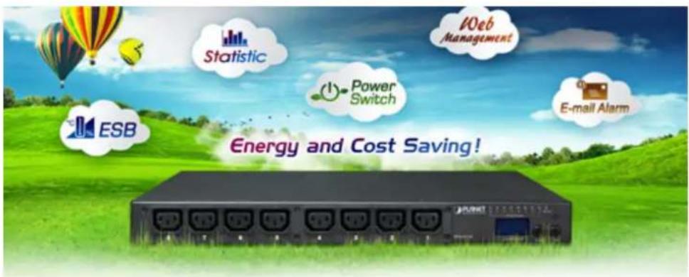
PLANET IPM-4220/8220 is a 4-/8-port IP Power Management (IPM) device that provides the useful function of managing power for any combination to connect with itself. With the innovative IP-based technology, PLANET has made the traditional power management equipment into true networking devices.
Intelligent Power Management
The IPM-4220/8220 offers 4/8 power outlets, each of which can be controlled or monitored individually by the console or SNMP manager software or web interfaces. They allow users to access, configure, and manage many networking devices at the same time from remote locations to save valuable time.
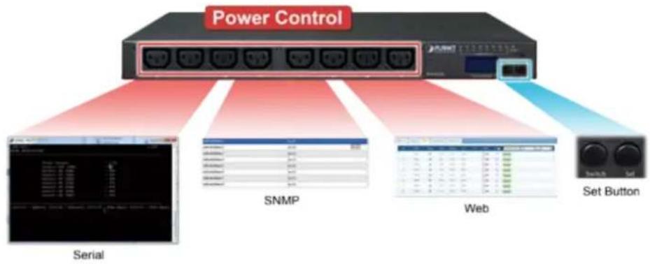
flowchart
graph LR
    A["Power Control"] --> B["Serial"]
    A --> C["SNMP"]
    A --> D["Web"]
    A --> E["Set Button"]
Electric Current Monitored on Display
The aggregate current draw per rack PDU is displayed on the unit via a digital display. The local digital display helps installers avoid overloaded circuits by providing a visible warning when the current draw is close to the maximum amperage draw of the strip.
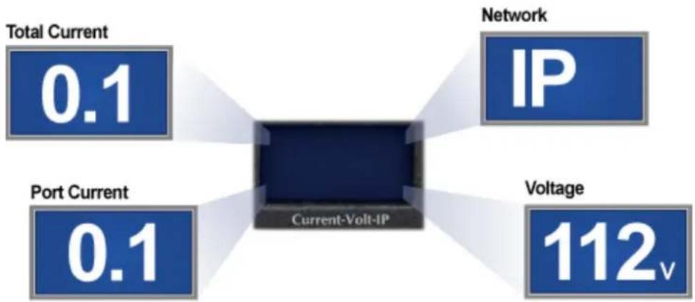
flowchart
graph TD
    A["Total Current 0.1"] --> B["Current-Volt-IP"]
    C["Port Current 0.1"] --> B
    D["Network IP"] --> B
    E["Voltage 112v"] --> B
Scheduled Power On/Off
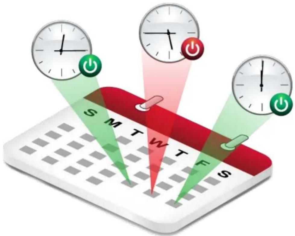
The IP-based Switched Power Manager allows you to pre-define a power schedule for IT equipment. It alerts users to an upcoming shutdown, and then waits a predefined amount of time to allow users to finish their work and sign off.
Overload Protection
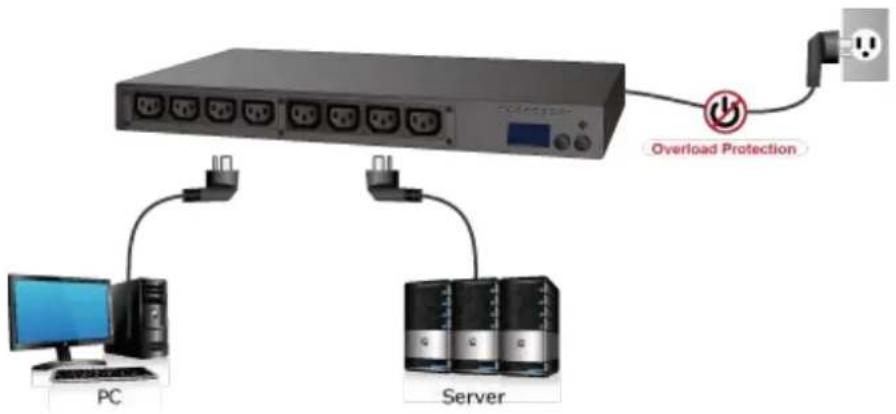
Securing you against the risk of getting the entire circuit cut off, commonly happened with ordinary power distribution units (PDUs), when there is overloaded power, PLANET PDU, with a built-in circuit breaker and reset switch, ensures the stability of power distribution among its equipment. Its 16-amp circuit breaker prevents dangerous circuit overloads that could damage the equipment.
3840 watts
Max. permissible load
flowchart
graph TD
    A["PC"] --> B["Server"]
    C["Overload Protection"] --> D["Power Supply"]
    B --> D
    style A fill:#f9f,stroke:#333
    style B fill:#ccf,stroke:#333
    style C fill:#cfc,stroke:#333
    style D fill:#fcc,stroke:#333
Energy and Cost Saving
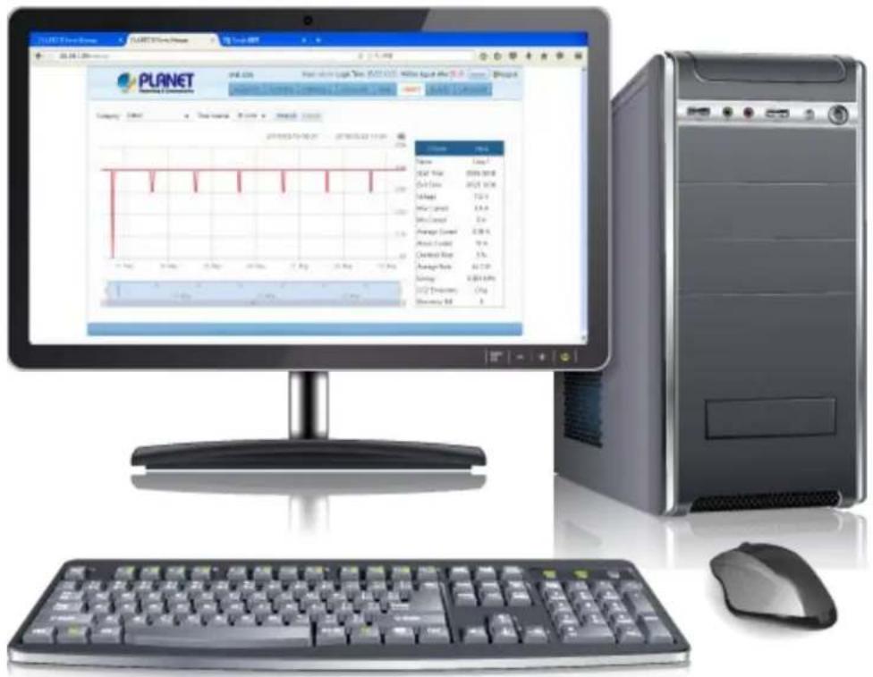
You can also check the current energy consumption in your office within the configuration interface of the IPM-4220/8220. It helps you reduce energy consumption, thus saving expenses on utilities.
1.3 Features
Hardware
■ Desktop/1U rack-mount size design
■ IEC outlet models
■ 4/8 power outlets that support real-time current image monitoring
■ 4/8 LEDs show power status for each power outlet
■ LCD panel displays current, maximum alarm and network information
■ Switch/Set button to lock up protection to avoid modification (For IPM-8220)
■ Buzzer will ring when total power consumption value exceeds set value
■ Circuit breaker can avoid damage that is caused by overload
■ Versatile sensors supported through environmental sensor box (ESB) inputs
Power Distribution
■ Maximum Amps/Inlet: IEC 16A for 1 inlet
■ Maximum Amps for 4/8 Outlets: IEC 16A for 4/8 outlets
■ Full Frequency Range: 50\~60Hz
■ Supports multiple power control methods – Wake on LAN, System After AC Back, Kill the Power
Remote Access
■ Remote power control via TCP/IP and a built-in 10/100Mbps Ethernet port
■ Multi browsers support (IE, Google, Firefox, Safari, Opera, Netscape)
Management
■ Provides Install Wizard to ease users' setting of parameters
■ Events notification by sending pop-up message, trap, SMS or e-mail
■ Supports Management Information Base (MIB) files for SNMP
■ Naming support for outlets
■ Power-on sequencing intelligently turns on/off devices based on event occurrence or planned schedule
■ Voltage, current, wattage and total kWh report
■ Sets over-current watchdog for power outlet
■ External UPS can be installed for a possible power outage
Security
■ Web page supports 1024-bit SSL security encryption transmission
■ Supports Secure Socket Layer V3 and Secure Shell V1 protocols
■ Administrator and multiple users with password protection for double-layer security
■ IP Filtering -- Address-specific IP security masks to prevent unauthorized access
1.4 Specifications
| Product | IP-based 4-/8-port Switched Power Manager | |
| Hardware Specifications | ||
| IPM-4220 | IPM-8220 | |
| Outlet Power Port 4 8 | ||
| Inlet Power Port 1 | ||
| Sensor Port | 1 RJ11-type port, 6P | |
| Com Port | 2 RJ45-type ports | |
| Network Connector | 1 RJ45 port for 10/100BASE-TX | |
| Button | 1 switch/set button1 reset button | 1 switch button1 set button1 reset button |
| LED | 1 IP LED1 alarm LED1 system LED1 reset and warning LED4 outlet status LEDs | 1 alarm LED1 system LED1 reset and warning LED8 outlet status LEDs |
| LCD Panel | Displays total current and IP | Displays total current, max. alarm, voltage and IP |
| Housing Metal | ||
| Dimensions (W x D x H) | 332 x 153 x 44 mm | 432 x 153 x 44 mm |
| Weight | 1.6kg | 2.5kg |
| Installation | Desktop | 1U rack-mountable, desktop |
| Buzzer | 1 | |
| Breaker | 1 x 16A | |
| Power Distribution | ||
| Inlet Power | Outlet Power | |
| Voltage | 100~240V | |
| Frequency | 50~60Hz | |
| Connection | 1 x IEC320 C20 | 4/8 x IEC320 C13 |
| Maximum Current | 16A | |
| Maximum Line Current | - | 10A |
| Management | |
| User Account | General/Manage/Administrator |
| Management Utility | Web browser, SNMP software, Windows-based utility, Telnet |
| Security | IP filter/MAC filter/Secure 128-bit SSL encryption |
| Standards Conformance | |
| Computer Interface | IEEE 802.3 10BASE-TIEEE 802.3u 10/100BASE-TX |
| Regulatory Compliance | CE, FCC |
| Environments | |
| Operating Temperature | 0 ~ 60 degrees C |
| Operating Humidity | 0 ~ 90% |
| Operating Altitude 0-4500 meters | |
Chapter 2. Hardware Interface
2.1 Physical Descriptions
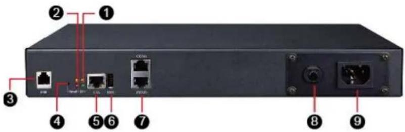
IPM-4220 Rear Panel
IPM-4220 Front Panel
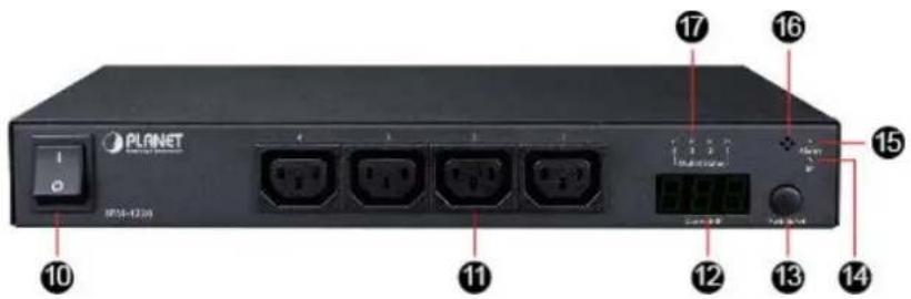
| 1 | System Indicating LightSlow flashing: Normal operatingRapid flashing: Normal updating |
| 2 | Reset and Warning Indicating Light |
| 3 | Temperature/Humidity Port for IPM-ESB Connection |
| 4 | Reset Button |
| 5 | RJ45 Ethernet Port |
| 6 | USB Connected Port (Future Feature) |
| 7 | COM2/12 Com Ports provided to enable terminal control, API control and 2 mutual cascading |
| 8 | Circuit Breaker Protection |
| 9 | Power Inlet |
| 10 | Power On/Off Switch |
| 11 | Power OutletNote: The maximum output current is 16 amps. |
| 12 | LCD Panel: To display total current and IP |
| 13 | Switch/Set buttonProvide LCD panel in order to switch the total current and IP; set alarm current |
| 14 | IP Indicating LightLights remaining lit: IP displaying |
| 15 | Alarm Indicating LightLights remaining lit: Alarm has occurredSlow flashing: There is current overloading |
| 16 | Buzzering |
| 17 | Power Outlet Indicating Light |
IPM-4220 Panel Operation
The first mode of LCD is total current, switching with the Switch/Set button to show the regular sequence of total current, maximum current and IP shown below:
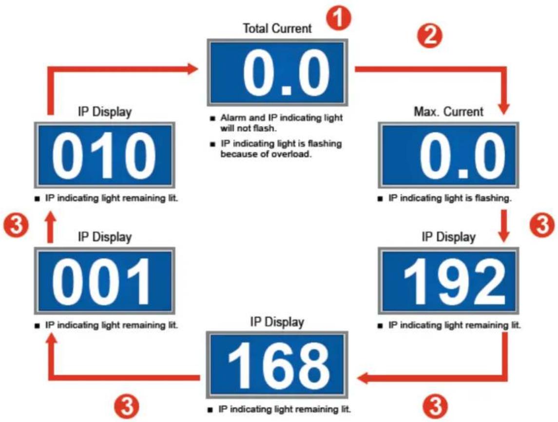
flowchart
graph TD
    A["010"] -->|IP indicating light remaining lit.| B["0.0"]
    B -->|Alarm and IP indicating light will not flash.
IP indicating light is flashing because of overload.| C["192"]
    C -->|IP indicating light remaining lit.| D["168"]
    D -->|IP indicating light remaining lit.| E["001"]
    E -->|IP indicating light remaining lit.| F["3"]
    F -->|IP indicating light remaining lit.| G["10"]
    G -->|Max. Current 0.0| H["2"]
    H --> I["3"]
    I --> J["4"]
    J --> K["5"]
    K --> L["6"]
    L --> M["7"]
    M --> N["8"]
    N --> O["9"]
    O --> P["10"]
    P --> Q["11"]
    Q --> R["12"]
    R --> S["13"]
    S --> T["14"]
    T --> U["15"]
    U --> V["16"]
    V --> W["17"]
    W --> X["18"]
    X --> Y["19"]
    Y --> Z["20"]
    Z --> A
LCD menu shows the total current. Hold the Switch/Set button for 3 seconds (until a long beep is heard) to enter alarm current setting. Press the Switch/Set button to increase the alarm current by 0.5A in each press. Hold the Switch/Set button for 3 seconds (until a "beep" is heard) to save the setting.
- ② Press the Switch/Set button until it shows the maximum current. → Hold the Switch/Set button for 3 seconds (until a long beep is heard) to adjust to a zero point.
■ 3 Press the Switch/Set button to switch the display of each IP address.
IPM-8220 Rear Panel
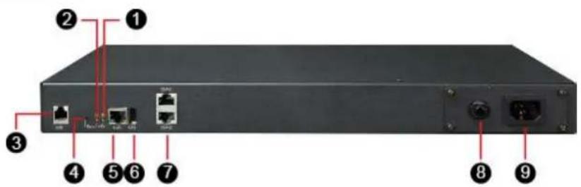
IPM-8220 Front Panel
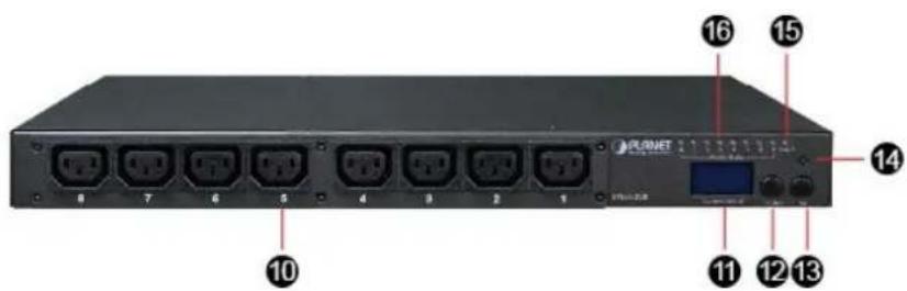
| 1 | System Indicating LightSlow flashing: Normal operatingRapid flashing: Normal updating |
| 2 | Reset and Warning Indicating Light |
| 3 | Temperature/Humidity Port for IPM-ESB Connection |
| 4 | Reset Button |
| 5 | RJ45 Ethernet Port |
| 6 | USB Connected Port (Future Feature) |
| 7 | COM2/12 Com Ports provided to enable terminal control, API control and 2 mutual cascading |
| 8 | Circuit Breaker Protection |
| 9 | Power Inlet |
| 10 | Power OutletNote: The maximum output current is 16 amps. |
| 11 | LCD Panel: To display total current, branch 1, branch 2, voltage and IP |
| 12 | Switch ButtonProvide LCD panel in order to switch the total current, power switch control and IP |
| 13 | Set ButtonProvide LCD panel in order to switch the total current, branch current, voltage, power switch current,power switch control and IP; set alarm current |
| 14 | Buzzer |
| 15 | Alarm Indicating LightLights remaining lit: Alarm has occurredSlow flashing: There is current overloading |
| 16 | Power Outlet Indicating Light |
IPM-8220 Current Panel Operation
When the LCD panel only displays figures and the sign of "A (AMP)", it means total current. Switch with the Set button to show the following sequence:
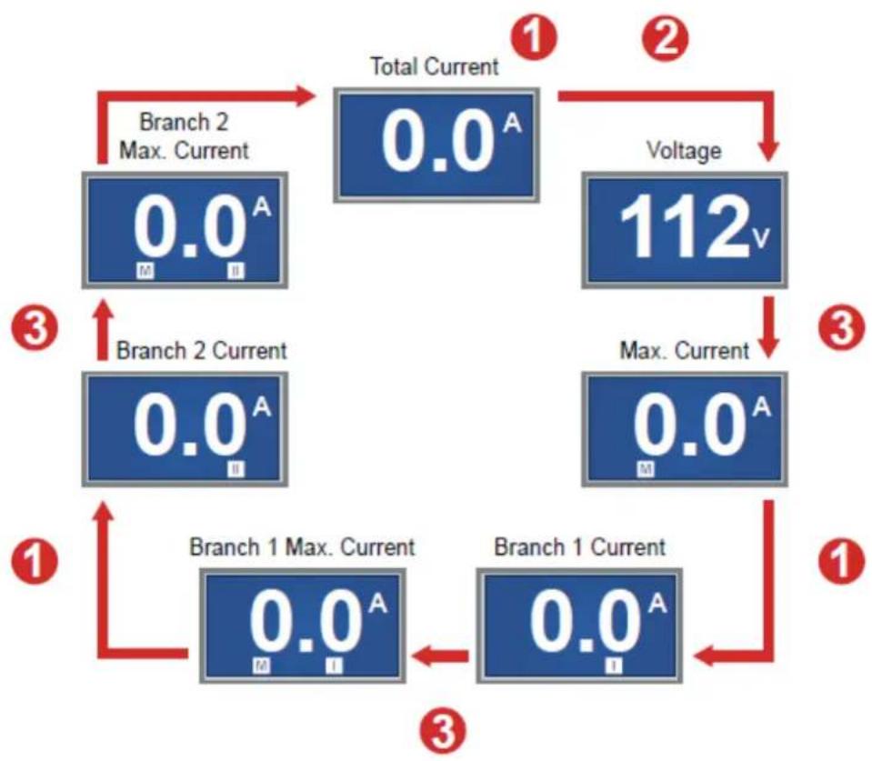
flowchart
graph TD
    A["0.0A M II"] -->|Branch 2 Max. Current| B["0.0A"]
    B --> C["0.0A"]
    C --> D["112v"]
    D -->|Voltage| E["0.0A M"]
    E --> F["0.0A"]
    F --> G["Branch 1 Max. Current"]
    G --> H["0.0A"]
    H --> I["0.0A"]
    I --> J["Branch 1 Current"]
    J --> K["0.0A"]
    K --> L["Branch 2 Current"]
    L --> M["0.0A"]
    M --> N["1"]
    N --> O["1"]
    O --> P["3"]
    P --> Q["Branch 2 Max. Current"]
    Q --> R["0.0A"]
    R --> S["112v"]
    S --> T["0.0A"]
    T --> U["Branch 1 Max. Current"]
    U --> V["0.0A"]
    V --> W["Branch 1 Current"]
LCD menu shows total current and current values of branch 1 and branch 2. → Hold the Set button for 3 seconds (until a long beep is heard) to enter alarm current setting. → Enter flash mode (LCD will flash after entering setting mode; "S" and "W" will display at the bottom of LCD). → Press the Set button to increase the alarm current by 0.5A in each press. → Hold the Set button for 3 seconds (until a "beep" is heard) to save the setting.
■ ② Press the Set button to show the voltage information.
- 3 Press the Set button to show the maximum current record of all branches (branch 1 and branch 2). Hold the Set button for 3 seconds (until a long beep is heard) to adjust to a zero point.
IPM-8220 Power Outlet Panel Operation
When the LCD panel shows figures and "0", the information shown is the branch circuit power outlet. By clicking the Set button, the following information will be displayed in sequence:
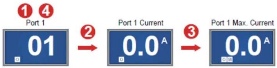
flowchart
graph LR
    A["Port 1"] --> B["01"]
    B --> C["Port 1 Current"]
    C --> D["0.0A"]
    D --> E["Port 1 Max. Current"]
■ 1 Press the Switch button to Port 1\~8 mode.
- ② Press the Set button to show power outlet current. Hold the Set button for 3 seconds (until a long beep is heard) to enter power outlet alarm current setting. Enter flash mode (LCD will flash after entering setting mode; "S", "O" and "W" will display at the bottom of LCD). Press the Set button to increase the alarm current by 0.5A in each press. Hold the Set button for 3 seconds (until a "beep" is heard) to save the setting.
- ③ Press the Set button to show "maximal power outlet current record", Hold the Set button for 3 seconds (until a long beep is heard) to adjust to a zero point.
- 4 Hold the Switch button for 3 seconds (until a long beep is heard) in Port 1\~8 mode. → Enter Power On/Off mode ("L" will be added in front of the original line number). → Double-click the Set button to switch between power on and off.
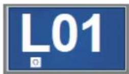
- When LCD panel displays "Port 1\~8 mode". Hold the Switch button for 3 seconds (until a long beep is heard) till "LOC" displayed. It means this circuit power is locked and cannot be
operated through the panel. Please go to the Peripheral of web UI and check the setting.

IPM-8220 IP Panel Operation
Press the Switch button to show words like "IP" → Press the Set button to switch the display of each IP address. IP can only be set by the web page rather than the LCD panel.

flowchart
graph LR
    A["IP"] --> B["192"]
    B --> C["168"]
    C --> D["001"]
    D --> E["020"]
2.2 Product Concatenation
If the controlled device and server have the function of redundant power, then shut-down of the device requires power-off of both two power supplies. Therefore, product concatenation is provided to reach the goal of power-on/off at the same time as two power supplies.
- For concatenation of the two Switched IPM, please pay attention to the following notices:
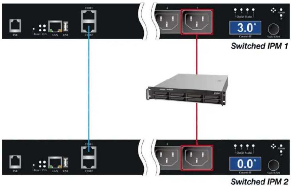
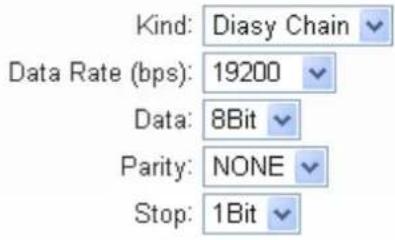
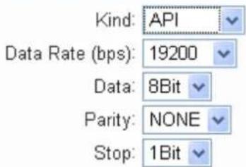
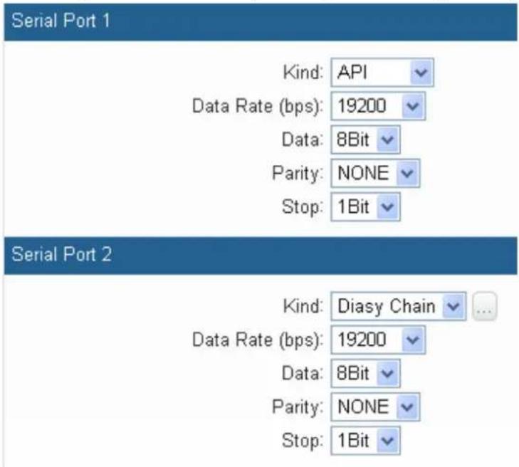
- For the main power supply control of the Switched IPM, set the UART type as daisy chain.
Serial Port 2
- For the secondary power supply control of the Switched IPM, set the UART type as API. The power outlet of the main and secondary remote power control devices can be set to determine the power outlet requiring concatenation.
Serial Port 1
2.3 Installation Precautions
- Please set the maximum power-off protection allowed by power circuit as per the rated current information indicated on the device with reference to the local state rules, safety procedures and disconnection or deviation.
■ The unit can only be connected to a grounded power outlet or system.
■ Make sure the total current output of all the connected systems is within the rated current indicated on the device.
■ The test results of this device may be inaccurate giving unstable power supply. - Avoid using this device in places near water or moisture environments.

Note
In order to avoid a fire hazard or risk of electric shock, do not expose the product to rain or moisture.
■ Use the attachments/accessories specified by the manufacturer only.
- Please avoid any items or liquids entering the device because their contact with dangerous voltage points or short-circuit parts may cause a fire or electric shock.
2.4 Hardware Installation
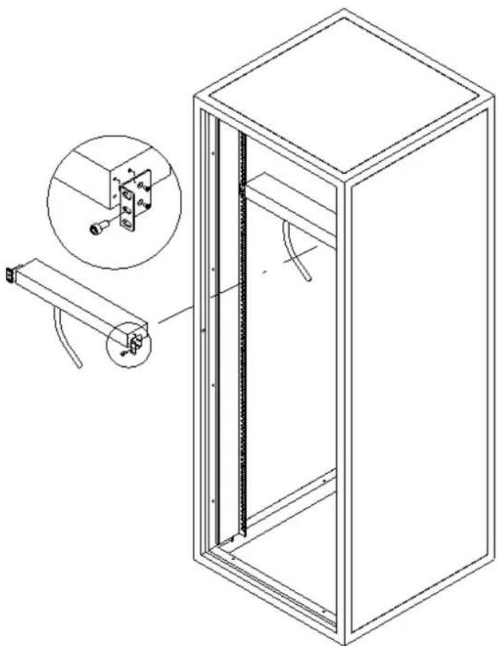
The IPM-8220 provides a standard 19-inch rack for the installation of devices. Please use the rack installation accessories attached with the product package (standard accessory for the IPM-8220). First install the accessories to the device and then the device to the rack.
natural_image
Technical line drawing of a cabinet with an inset showing a close-up of the internal components (no text or symbols present)
Note
Please make sure all the units connected are powered off before the installation of the device and take other necessary precautions during the installation.
2.5 Initial Utility Installation
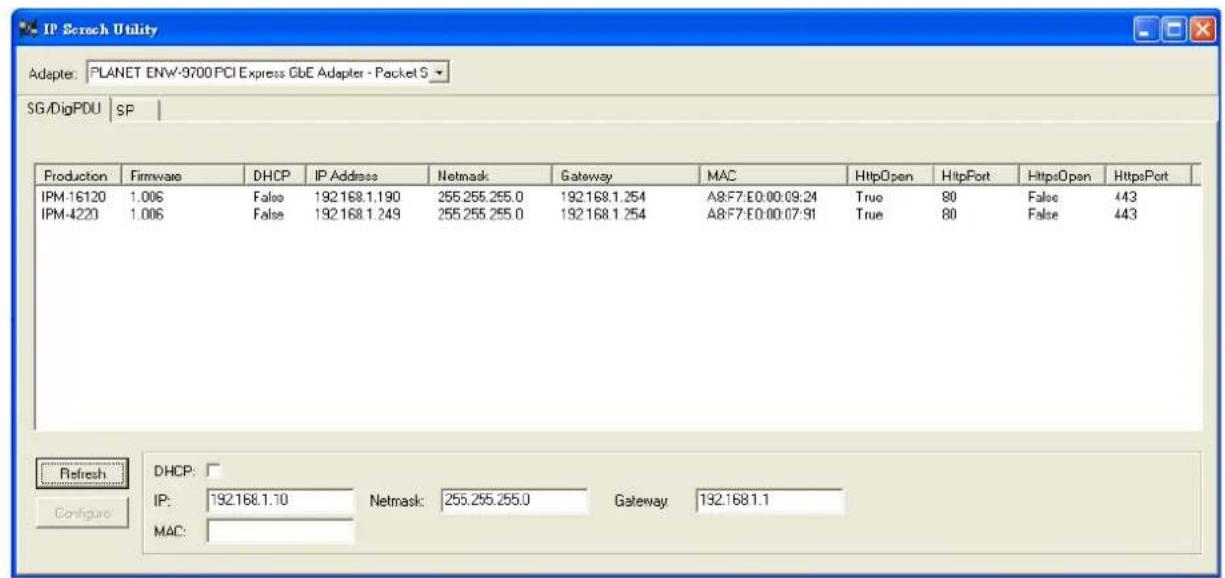
PLANET "IP Search" is a software utility used to search the IP Metered PDU product on a network quickly and with ease.
Step 1: Please download the IP Search tool from PLANET Download Center.
Step 2: Please press the "Refresh" button to find out your IP Metered PDU.

Note
- Before searching the IP, please make sure your PC is in the same IP segment as control gateway.
- Do not set double IP addresses on the same LAN card.
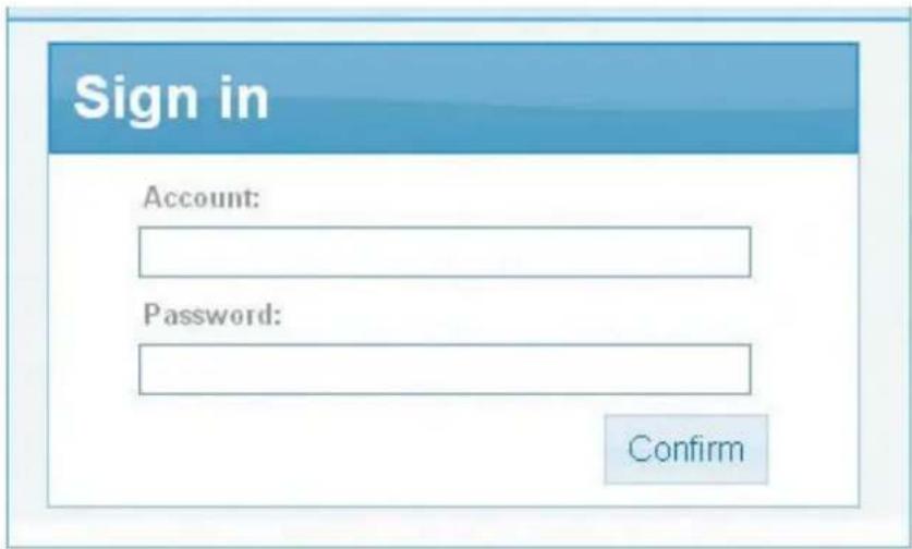
Step 3: Enter the IP address and log in to the homepage of IPM.
Chapter 3. Quick Setup
In this section users can learn how to query device IP and how to set language, account password, network and time zone through daemon.
3.1 Network Connection
After the device is connected to the network, IP can be acquired automatically through DHCP server (The device IP will be preset to 192.168.0.10 if there is no DHCP server.). The acquired IP can be displayed on the LCD panel or device IP can be searched by IP Search Utility.
| Default DHCP Client | On |
| Default IP Address | 192.168.0.10 – if no DHCP existed in the network |
| Default Port | 80 |
| Default Login User Name | Set itself |
| Default Login Password | Set itself |
| Search Tools | ip_search |
3.2 Setup Wizard
When you use the Switched IPM for the first time, after it is connected to the Internet, browser would pop up Setup Wizard asking you to provide language, account, password, network and time zone.
Step 1: Language Selection
Select your language currently available in English, Traditional Chinese and Simplified Chinese, and press Next to continue.

Step 2: Account Setting
This menu is for setting the admin account and password of the device. Press Next to continue.
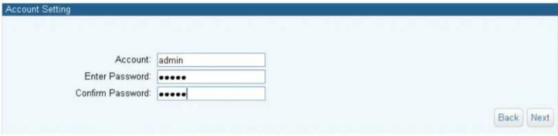
Step 3: Host Setting
The product is assigned dynamically (DHCP). To specify a fixed IP address, please fill in IP Address, Subnet Mask and Gateway. Press Next to continue.
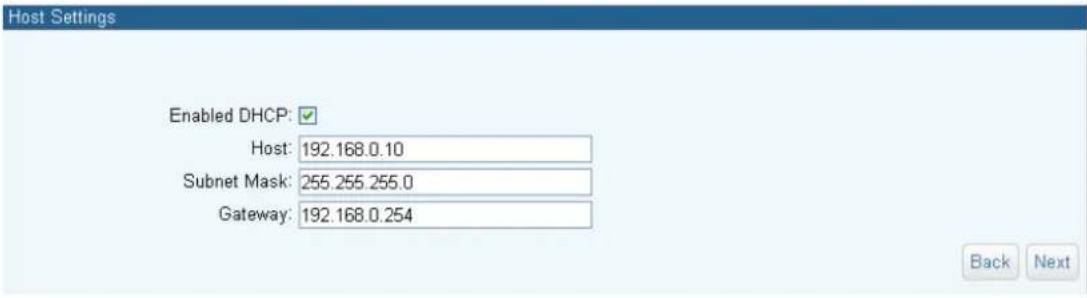
Step 4: DNS Setting
Key in the DNS server, provided by ISP providers, and then you can set up two DNS servers. Press Next to continue.
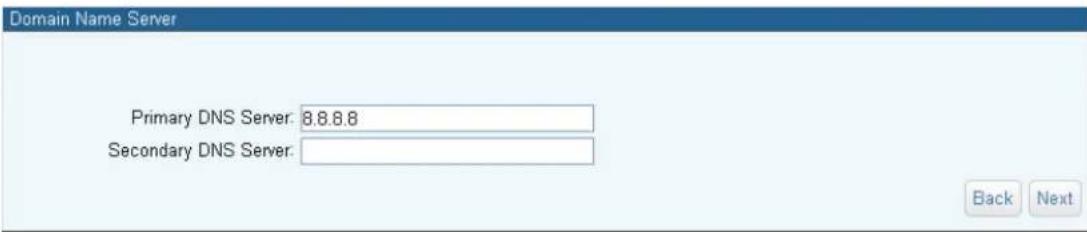
Step 5: Web Server
Https can help protect streaming data transmission over the internal on the higher security level. You can select the connection type. "Https" means user cannot connect the camera via Http protocol. The Https path will be: "https://(IP address)/". If you select "Http & Https", both the Http and Https path can be used to access the device. Press Next to continue.
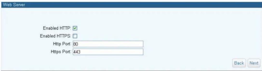
Step 6: Time Format
Select the time format to show in the system. Press Next to continue.

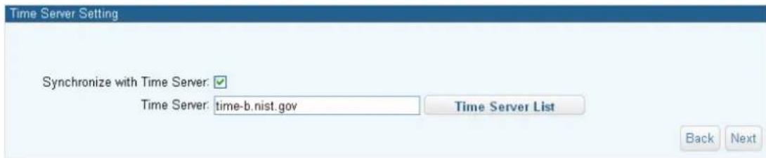
Step 7: Time Server Setting
User can set up device time synchronized with Time Server. Press Next to continue.
Step 8: Time zone
Please fill in the time zone where the device is. The system is based on Greenwich Mean Time, and thus, an accuracy setting to time zone may affect the time record of events and chart. Press Next to continue.

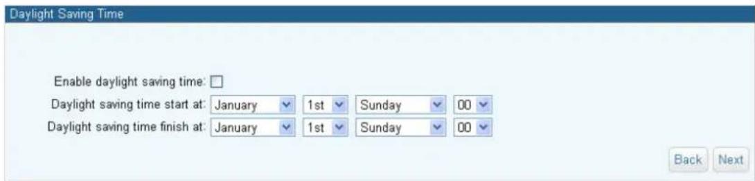
Step 9: Daylight Saving Time
Set the Daylight saving time from Sunday to Saturday. Press Next to continue.
Step 10: General Setting
You may set up operational overtime in this section. Press Finish to save all settings.

Chapter 4. Web-based Management
This section provides instructions about how to use the web interface to configure and control the IP Power Manager remotely.
4.1 Monitor
After a successful login, the web page will display the following operation menu where each part is illustrated below:
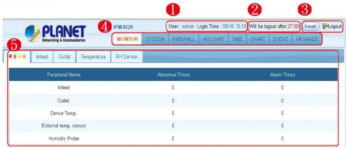
| 1 | User login information |
| 2 | Reset the logout time |
| 3 | System logout |
| 4 | Function bar |
| 5 | Operation block |
4.1.1 Infeed
Display the current, voltage, power, frequency, power factor, watts and such information.

| Parameters Description | |
| Name | Description of each power infeed. |
| Status | Each light signal has three states: "Normal", "Alert" and "No Access".Monitor Normal: "Offline Monitor" is checked. And external temperature is not higher than "High Alarm" or lower than "Low Alarm" setting.Monitor Alert: "Offline Monitor" is checked. And external temperature is higher than "High Alarm" or lower than "Low Alarm" setting.No Access: Means user does not have any authority to operate the infeed.Move the mouse over the signal light for its detailed information, and the menu is displayed as follows: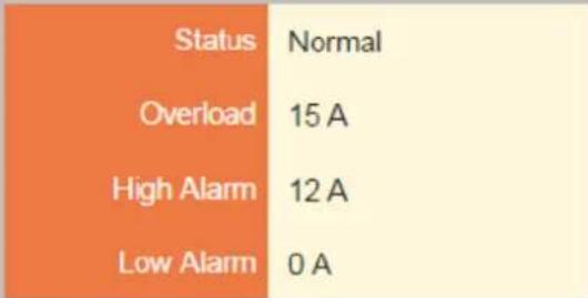 |
| Total | Display the total current consumption of the device. |
| Voltage | Display the voltage of the current input power. |
| Power | Display the consumption power value of the current input power. |
| Frequency | Display the voltage frequency of current input power. |
| Power factor | Display the power factor of current input power. |
| KWh | Display the consumption watt-hour of the device since the last zeroing. |
| State dropdown menu | It provides four methods for users to check up infeed status: All, abnormal, warning and normal. Relevant info would show as correspondence event has been chosen. |
| Setup | Press "Setup" and the window for setting the input power of this circuit will be shown. |
Parameters Description
Name : Loop 1
Overload:16.0
A Max: 16 A
High Alarm: 12.8
A Max: 16 A
Low Alarm : 0.0
A Max: 16 A
Voltage : 0
V
Name: Description of each power infeed.
Overload Current: Input the current value of the overload power; alarms will be given when the input power current exceeds this alarm value.
High Alarm: Set up the values of high infeed alarm. When current is higher than you set, the alarm will occur.
Low Alarm: Set up the values of low infeed alarm. When current is lower than you set, the alarm will occur.
Voltage: Set the input power voltage, and when the device has no watt-hour module, this value will be taken as computing power and relevant information.
4.1.2 Outlet (For IPM-4220)
Display PC connected with device statement and switch info; power on/off can be directly operated on the menu.

Infeed
Outlet
Temperature
RH Sensor
Daisy Chain

Parameters Description
| Name | If user has no access to this route after signing in, the name will be "No Access". |
| PC | When the power outlet connects with a computer, in order to allow the computer to shut down normally before powering off, the computer must be installed and execute a safe shutdown program (Please go to PLANET website to download this program). After relevant parameters are set, safe shutdown program will be |
| Parameters | Description |
registered on the computer and the computer state will show the sign of giving normal registration. There are two computer states for power outlet: "Normal online state", and "Abnormal online state". : Normal online state : Abnormal online state Move the mouse over the sign for its detailed information, and the menu is displayed as follows: 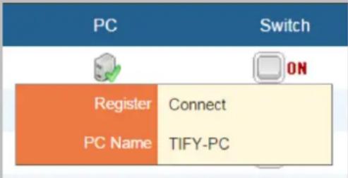 | |
| Switch | Displays the current power outlet on-off state. For operation of power outlet on/off, click the on/off icon with the mouse for commands of "On", "Off", and "Reboot". |
| Sync Port | To be displayed after concatenation is enabled, representing the power outlet of this line will be linked with the outlet displayed in the Sync Port of concatenated device. |
| All | To operate many switched IPM at once, please follow these steps: Step 1. Mark on the checkbox of switches or All that you want to operate. Step 2. Select the action you want (ON, OFF, REBOOT or SHORT ON). Step 3. Click Confirm to control the switch you select. |
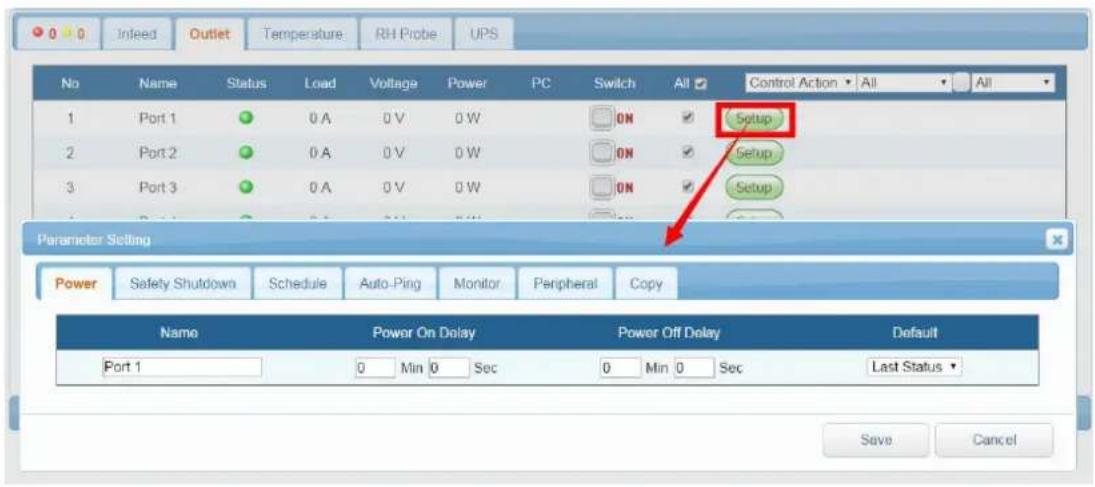
| Setup | Press Setup and the following window will appear. Users can set the outlet power, safe shutdown, work schedule, auto-ping, parameter and copy. Please refer to the 4.2 Outlet Power Setup for more understanding. |
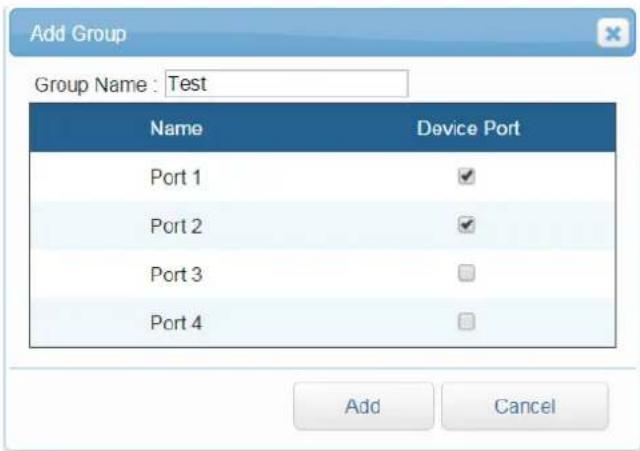
| Group Management | You may Add, Delete, Modify the group and also assign them with special switch. Descriptions are shown below: Select: You may select existing groups for deletion and revision from the drop-down list.Delete Group: Delete the group user that is not necessary.Add Group: Click on Add Group to create a group. After clicking it, Add Group window will pop up. Enter group name and mark the ports you expect to manage, and press Add to build the group, continuously adding is permitted here. Press Cancel to return to main tab.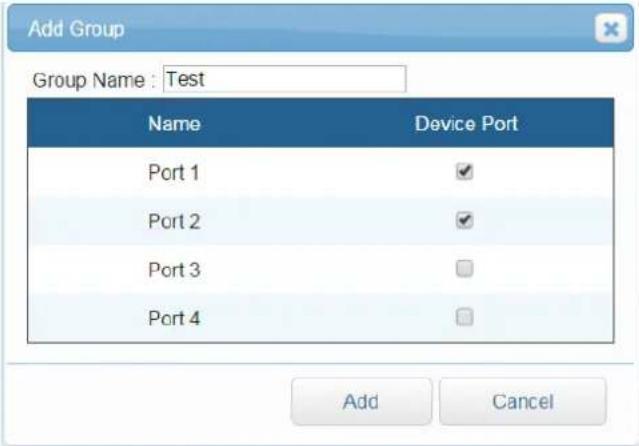 |
4.1.3 Outlet (For IPM-8220)
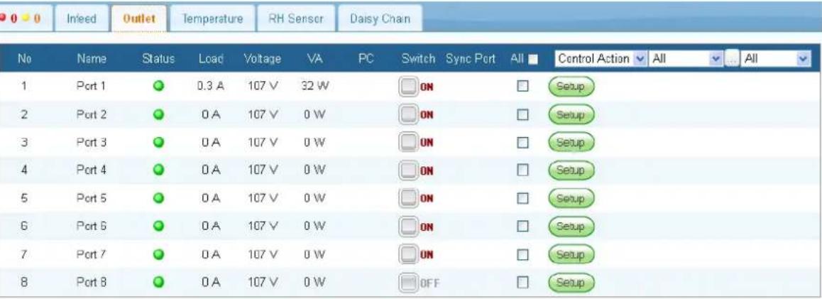
Display the current, voltage, power of power outlet and states of computer and switch; power on/off can be directly operated on the menu.
 |
| Parameters Description | |
| Name | If user has no access to this route after signing in, then the name will be "No Access". |
| Status | Power outlet current has three states: "Normal", "Alert" and "No Access". |
| Normal: “Offline Monitor” is checked. And external temperature is not higher than “High Alarm” or lower than “Low Alarm” setting.Alert: “Offline Monitor” is checked. And external temperature is higher than “High Alarm” or lower than “Low Alarm” setting.No Access: Means user does not have any authority to operate the infeed.Move the mouse over the signal light for its detailed information, and the menu is displayed as follows:Status NormalOverload 14AHigh Alarm 12.0ALow Alarm 0A | |
| Load | Display the current consumption of the power outlet. |
| Voltage | Display the voltage of the power outlet. |
| VA | Display the consumption power value of the current power outlet. |
| PC | When the power outlet connects with a computer, in order to allow the computer to shut down normally before powering off, the computer must be installed and execute a safe shutdown program (Please go to PLANET website to download this program). After relevant parameters are set, safe shutdown program will be registered on the computer and the computer state will show the sign of giving normal registration. There are two computer states for power outlet: "Normal online state", and "Abnormal online state".Normal online stateAbnormal online stateMove the mouse over the sign for its detailed information, and the menu is displayed as follows: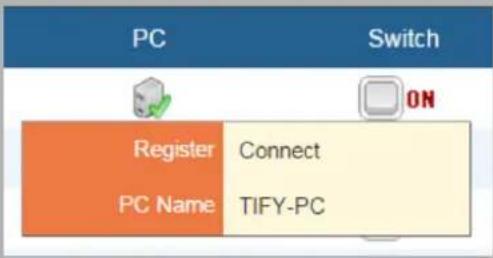 |
| Switch | Displays the current power outlet on-off state. For operation of power outlet on/off, click the on/off icon with the mouse for commands of "On", "Off", and "Reboot". |
| Sync Port | To be displayed after concatenation is enabled is the power outlet of this line that will be linked with the outlet displayed in the Sync Port of concatenated device. |
| All | To operate many switched IPM at once, please follow these steps:Step 1. Mark on the checkbox of switches or All that you want to operate.Step 2. Select the action you want (ON, OFF, REBOOT or SHORT ON).Step 3. Click Confirm to control the switch you select. |
| Setup | Press Setup and the following window will appear, and users can set the outlet power, safe shutdown, work schedule, auto-ping, monitoring, parameter and copy. Please refer to the 4.2 Outlet Power Setup for more understanding. |
| Group Management | You may Add, Delete, Modify the group and also assign them with special switch. Descriptions are shown below:Select: You may select existing groups for deletion and revision from the drop-down list.Delete Group: Delete the group user that is not necessary.Add Group: Press Add Group to create a group. After clicking it, Add Group window will pop up. Enter group name and mark the ports you expect to manage, and press Add to build the group, continuously adding is permitted here. Press Cancel to return to main tab. |
Parameters Description
4.1.4 Temperature
Display the information of Offline Monitor, Status and Temperature Value of the sensor.


| Parameters Description | |
| Name | Description of temp port. |
| Offline Monitor | Check to enable to monitor the state of temp sensor. When abnormal temp occurs, device will send alert via the specified email. |
| Status | Temperature sensor has 6 states: "Monitor Normal", "Monitor Alert", "Monitor Off-line, the "Non-monitor Normal" "Non-monitor Alert", and "Non-monitor Off-line".Monitor Normal: "Offline Monitor" is checked. And external temperature is not higher than "High Alarm" or lower than "Low Alarm" setting.Monitor Alert: "Offline Monitor" is checked. And external temperature is higher than "High Alarm" or lower than "Low Alarm" setting.Monitor Off-line: "Offline Monitor" is checked. Temperature Probe is not connected to PDU now.Non-Monitor Normal: "Offline Monitor" is not checked. And external temperature is not higher than "High Alarm" or lower |
than “Low Alarm” setting.Non-Monitor Alert: “Offline Monitor” is not checked. And external temperature is higher than “High Alarm” or lower than “Low Alarm” setting.Non-Monitor Off-line: “Offline Monitor” is not checked. Temperature Probe is not connected to device now.Move the mouse over the icons for its detailed information, and the menu is displayed as follows: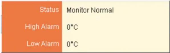 | |
| Temperature | Refer to the temperature value detected by the current temperature sensor. |
| State dropdown menu | This drop-down list offers four states for inquiry: "All", "Abnormal", "Alert", and "Normal" that will be displayed as per the temperature sensor state. |
| Setup | Name: Temperature sensor nameHigh Alarm: Set up the values of high temp alarm. When temp is higher than you set, the alarm will occur.Low Alarm: Set up the values of low temp alarm. When temp is lower than you set, the alarm will occur.Offline Monitor: Check to enable to monitor system. When temp is higher than you set, device will send alerts via email.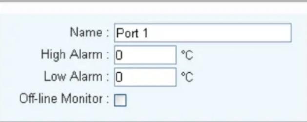 |
| Device Temp | Device Temp: Such device temperature.High Alarm: Set up the values of high temp alarm. When temp is higher than you set, the alarm will occur.Low Alarm: Set up the values of low temp alarm. When temp is lower than you set, the alarm will occur.Sensor state:Device Temp has 2 states: "Monitor Normal", and "Monitor Alert".Monitor Normal: "Offline Monitor" is checked. And external temperature is not higher than "High Alarm" or lower than "Low Alarm" setting.Monitor Alert: "Offline Monitor" is checked. And external temperature is higher than "High Alarm" or lower than "Low Alarm" setting.Move the mouse over the icons for its detailed information, and the menu is displayed as follows:StatusMonitor NormalHigh Alarm50°CLow Alarm0°C |
4.1.5 RH Sensor
Display the information of Offline Monitor, Status and Humidity Value of the sensor.
| No | Name | Off-line Monitor | Status | RH | All |
| 1 | Port 1 | 57 % | Setup |
| Parameters Description | |
| Name | Humidity sensor name. |
| Offline Monitor | Enabled to start monitoring, the device will send alarm data automatically through message or email whenever the humidity sensor name detects any abnormality. |
| Status | Humidity sensor has 6 states: "Monitor Normal", "Monitor Alert", "Monitor Off-line, the "Non-monitor Normal" "Non-monitor Alert", and "Non-monitor Off-line".Monitor Normal: "Offline Monitor" is checked. And external humidity is not higher than "High Alarm" or lower than "Low Alarm" setting.Monitor Alert: "Offline Monitor" is checked. And external humidity is higher than "High Alarm" or lower than "Low Alarm" setting. |
| Monitor Off-line: “Offline Monitor” is checked. Humidity Probe is not connected to PDU now.Non-Monitor Normal: “Offline Monitor” is not checked. And external humidity is not higher than “High Alarm” or lower than “Low Alarm” setting.Non-Monitor Alert: “Offline Monitor” is not checked. And external humidity is higher than “High Alarm” or lower than “Low Alarm” setting.Non-Monitor Off-line: “Offline Monitor” is not checked. Humidity Probe is not connected to device now.Move the mouse over the icons for its detailed information, and the menu is displayed as follows:Status Monitor AlertHigh RH Alarm 90 %Low RH Alarm 70 % | |
| RH | Refer to the humidity value detected by the current humidity sensor. |
| State dropdown menu | This drop-down list offers four states for inquiry: "All", "Abnormal", "Alert", and "Normal" that will be displayed as per the temperature sensor state. |
| Setup | Name: Humidity sensor nameHigh RH Alarm: Set up the values of high RH alarm. When humidity is higher than you set, the alarm will occur.Low RH Alarm: Set up the values of low RH alarm. When humidity is lower than you set, the alarm will occur.Offline Monitor: Check to enable to monitor system. When humid is higher than you set, device will sent alerts via email.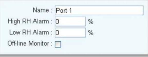 |
4.1.6 Daisy Chain
Display another connected switched IPM and status.
| Infeed | Outlet | Temperature | RH Sensor | Daisy Chain | |
| Model | Outlet Total | Status | |||
| IPM-4220 | 4 | ● | |||
| Parameters Description | |
| Model | The device of daisy chain. |
| Outlet Total | The outlet power port. |
| Status | Device of daisy chain has 2 states: "Monitor Normal", "Monitor Alert".Normal online state.Abnormal online stateMove the mouse over the icons for its detailed information, and the menu is displayed as follows:Status Monitor Normal |
4.2 Outlet Power Setup
Press Setup and the following window will appear; users can set the outlet power, safe shutdown, schedule, auto-ping, monitor (Only for IPM-8220), parameter and copy.
4.2.1 Power
Power setting list is mainly for setting the relevant information of power on/off of all lines.
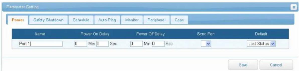
| Parameters Description | |
| Name | Description of each power outlet. |
| Power on delay | Set the number of seconds that device waits after a command is issued before applying power to an outlet. |
| Power off delay | Set the number of seconds that device waits after a command is issued before removing power from an outlet. |
| Sync Port | To be displayed after concatenation is enabled is the setting of the power outlet to be linked with the power outlet of the concatenated device. |
| Default | You may set preset switch status when local power is lost and comes back again. The statuses from the drop-down list are 1.ON, 2.OFF, 3 Last statuses before power was lost. |
4.2.2 Safe Shutdown
This page is for setting the computer device name connected to the power outlet. When users want to power off the outlet, firstly the computer connected should be shut down, and then switch off the power within the preset delay time.

| Parameters Description | |
| MAC | Please enter the Computer MAC address; the main function is computer remote Wake-up On LAN (WOL). |
| Delay Delivery | After power delay delivery time is enabled, the WOL command is delivered to computer. |
| Computer Name | Prior to the execution of safe shutdown, an application should be installed on the computer. After successful installation and registration, select the computer to be shut down from the drop-down list and then it will be displayed on the web page. |
4.2.3 Schedule
In this option, work schedule of the time for power outlet on/off is seen.

| Parameters Description | |
| Period | Set the work cycle of the power outlet; the cycle can be divided into Holiday, Month, Week, and Day. For example, if the cycle is Day, it means the power will perform the command at the set time every day. |
| Time | Set the work hours of the power outlet in the drop-down list. |
| Action | Set up power outlet to perform the command of "on", "off", "Reboot" or "Short on". |
| Delete | To delete the schedule, click the icon of "Delete" of the schedule. |
4.2.4 Auto-Ping
When the power supply connects with network devices, this menu can set the address of the network device, detect time interval, detection frequency, time of reboot and re-detection.

| Parameters Description | |
| Ping | Enable / Disable network detection. |
| Host | Network device address to be detected. |
| Ping Interval Time (Min.) | Execute the time interval of PING network devices. |
| Ping Times (Detection frequency) | Frequency of continuous abnormality during Ping network device, when the detected Ping failure frequency exceeds this set value; alert will be given through message or email. |
| Reboot | Set whether to reboot the network device when the detected Ping failure frequency exceeds this set value. |
Parameters Description
Re-Ping time (Min.)
The delay time for re-executing PING detection when the network device is on after network device reboots.
4.2.5 Monitor (Only for IPM-8220)
This function provides the ability to set power outlet current value, real-time off of power outlet in case of any current abnormality to avoid any damage to the devices connected with the outlet.

| Parameters Description | |
| Overload | Current value of the overload power, alarms will be given when the input power current exceeds this alarm value. |
| High alarm | Current value to be alerted when the power outlet current is too high. |
| Low alarm | Current value to be alerted when the power outlet current is too low. |
4.2.6 Peripheral
You may set up peripheral at this tab to monitor device and command it with On, Off, Reboot and Short on; set up different conditions with different peripheral types.

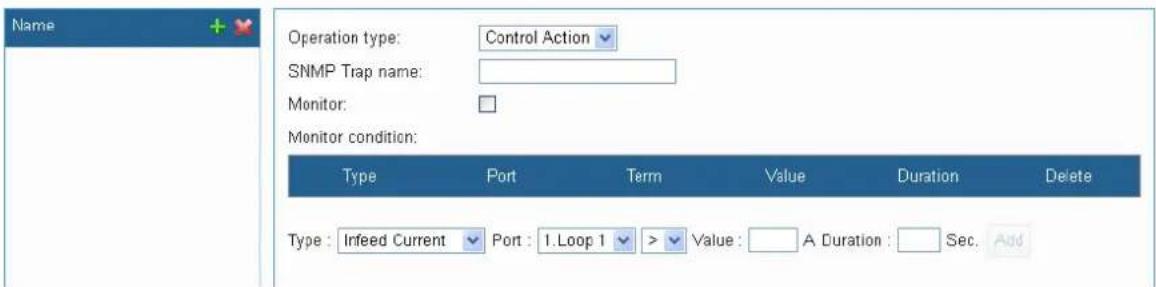
| Parameters Description | |
| Name | Add peripheral name. |
| Operation type | As the peripheral matches, it would perform the action for On, Off, Reboot or Short on. |
| SNMP Trap name | The Name shows up when sending alarm. English and number are only accessible. |
| Monitor | Check this item and the system would perform peripheral monitoring. |
Parameters Description
| Monitor condition | Type: Use drop-down list to select peripheral type. (e.g., External Temp)Port: Select the port to be monitored.Term: You may choose the symbols: > (higher), < (lower) and = (equal).Value: The device would command the order as temp reaches this value.Duration: The duration of value that is compliant with the peripheral conditions.Delete: After clicking the icon “X”, it would pop up a confirm window; your condition would be deleted. To command device, please reset the command. |

Note
All of the newly added conditions should match or the device will not do as you command; if only one condition is matched, device will unmove, either.
4.2.7 Copy
To quickly set up the power outlet parameter of each line, after setting the first line, the parameters can be copied to other lines of power outlet.
| Power | Safety Shutdown | Schedule | Auto-Ping | Monitor | Peripheral | Copy |

| No | Name | All |
| 1 | Port 1 | |
| 2 | Port 2 | |
| 3 | Port 3 | |
| 4 | Port 4 | |
| 5 | Port 5 | |
| 6 | Port 6 | |
| 7 | Port 7 | |
| 8 | Port 8 |
| Parameters Description | |
| Parameter drop-down menu | Allow to copy parameters such as power source setting, safe shutdown, schedule, auto-ping, current monitoring and peripheral. |
Parameters Description
Press "Save" after selecting a single power outlet or selecting all to copy the selected outlet parameters to the clicked power outlet(s).
4.3 System
On this web page, users can set Network, Email server, Message server, SNMP, SysLog, Peripheral parameters, and other relevant data.

4.3.1 Network Setting
This menu is mainly for setting the basic data of network.
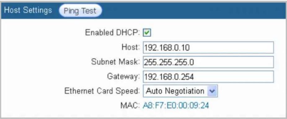
| Parameters Description | |
| Enabled DHCP | Use checkbox to enable DHCP. It will assign IP address. |
| Host | Assign the Network IP address for the power switch. |
| Subnet Mask | Set up the subnet mask info of this equipment. |
| Gateway | Set up the gateway port of this equipment. |
| MAC | Display MAC address. |
| Ping Test | Confirm whether the device with the IP address or DNS name is connected to the network. |
Domain Name Server
Primary DNS Server: 8.8.8.8
Secondary DNS Server:
| Parameters Description | |
| Primary DNS Server | Configure the IP and DNS server addresses for Network Adapter 1. |
| Secondary DNS Server | Configure the IP and DNS server addresses for Network Adapter 2. |
Web Server
Enabled HTTP: √
Enabled HTTPS: □
Http Port: 80
Https Port: 443
| Parameters Description | |
| Enabled Http | Allows browser to connect with smart monitor by HTTP. |
| Enabled Https | Allows browser to connect with smart monitor by HTTP SSL. |
| Http Port | Provides browser to communicate by HTTP with smart monitor. |
| Https Port | Provides browser to communicate by HTTP SSL with smart monitor. |
Firewall
Disable ICMP echo (ping) responses: □
| Parameters Description | |
| Disable ICMP Response | When Disable ICMP Response check box is selected, the examination will not be responded. |
4.3.2 Email Server
When there is a triggered warning from the setup of this PDU, this device will send out alert message to the preset email accounts.
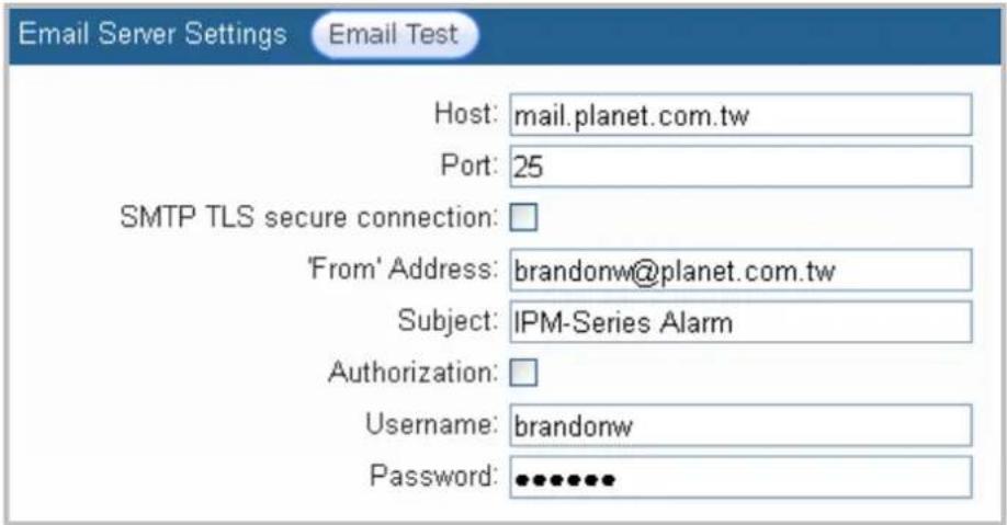
| Parameters Description | |
| Host | It is the Host IP address of the e-mail sending an alarm e-mail when an event occurs. |
| Port | It is the port of SMTP mail server. Default is 25. |
| SMTP TLS secure connection | Check to enable e-mail encryption. |
| From Address | It shows the sender's email address. |
| Subject | It shows the subject of the email. |
| Authorization | If the mail server needs to identify the user, please enable the checkbox and set up the account and password. |
| Username | The account to log in to mail server. |
| Password | The password to log in to mail server. |
| Email Test | After setting up the above info, you can send a test mail to make sure this function is normal. |
4.3.3 SMS Server
In this section, user can set up the warning message and info to the SMS server. The protocol here is supported by many SMS suppliers' (ISP) API. System will send out account, password, time, and related info via HTTP to the SMS server of ISP supplier or preset SMS server.
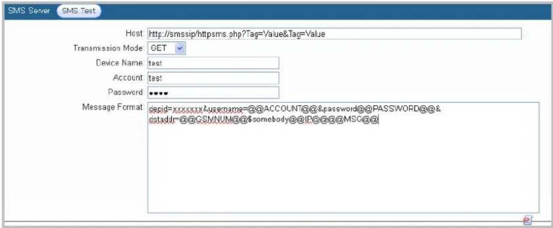
| Parameters Description | |
| Host | Host IP address of SMS Server. |
| Transmission Mode | Follow ISP suppliers' rules to send out short message via GET or POST protocol to sender's server. |
| Device Name | The name user wants to reveal. |
| Account | The account to fill in when sending SMS. The same as@@ACCOUNT@@. |
| Password | The password to fill in when sending SMS. The same as@@PASSWORD@@. |
| Message Format | We provide “auto bring-in” system with username, password, number, main host and message content. |
Parameters Description
| SMS Test | After setting up the above info, you can send a test mail to make sure this function is normal. |
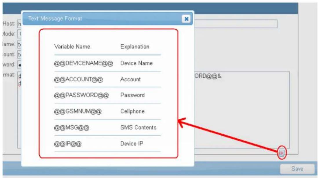
Parameters Description
| @@DEVICENAME@@ | The device name will show when sending a message. |
| @@ACCOUNT@@ | The account to send the message. |
| @@PASSWORD@@ | The password to send the message. |
| @@GSMNUM@@ | The number to send the message. |
| @@MSG@@ | Message content will show when sending a message. |
| @@IP@@ | Device IP will show when sending a message. |

Note
Message Format is related to your message content, a content may not stay the same as well.
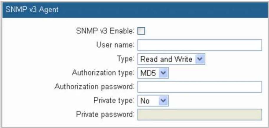
4.3.4 SNMP
You can set up SNMP Agent and SNMP Trap on this page.
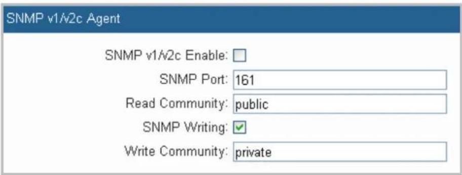
| Parameters Description | |
| SNMP v1/v2 Enable | Enable SNMP v1/v2. |
| SNMP Port | Set the destination port. Default is 161. |
| Read Community | Key-in passwords in the Community Name field. Default is public. |
| SNMP Writing | Select the checkbox to enable SNMP Write-in. |
| Write Community | Key-in passwords in the Community Name field. Default is private. |
| Parameters Description | |
| SNMP v3 Enable | Enable SNMP v3. |
| User Name | The name is SNMP v3 command. |
| Type | There are two types: Read Only, Read and Write. |
| Authorization Type | There are two types: MD5 and SHA. |
| Authorization Password | The password of authorization type. Use MD5 or SHA. |
| Private Type | There are two types: No and DES. |
| Private Password | For private password, use DES. Select DES type to key-in password. |
| SNMP Device Info | |
| sysName: | IPM-16120 |
| sysContact: | Administrator |
| sysLocation: | Office |
| Parameters Description | |
| sysName | The name displayed on SNMPAgent. |
| sysContact | The contact displayed on SNMPAgent. |
| sysLocation | The location displayed on SNMPAgent. |
| Host | Port | Authentication String | Delete |
| Host : | Port : 162 | Authentication String : | Add |
| Parameters Description | |
| Host | The Host IP address of SNMP Trap. |
| SNMP Trap Port | The phase connects to SNMP Trap. Default is 162. |
| Authentication String | The authentication string to access SNMP Trap. |
| SNMP Test | After setting up the above info, you can send a test mail to make sure this function is normal. |
4.3.5 Syslog
Remote Power Manager will send out text message to syslog receiver (syslog server). Please do as follows:

| Parameters Description | |
| Host | Enter Syslog Server Host IP. |
| Port | Enter Connect Port for Syslog Server. Default is 514. |
| Syslog Test | After setting up the above info, test it to make sure this function is normal. |
4.3.6 Serial Port (UART)
This menu is mainly for setting the data of COM 1 (UART 1), and COM 2 (UART 2).
| Parameters Description | |
| Kind | Serial Port 1There are four UART types: Disable, Console, API and UPSSerial Port 2There are four UART types: Disable, Daisy Chain, API and UPS.Disable: Cancel UART function.Console: Computer connects with the device through RS232 andoperate the device through terminal programAPI: Other devices can operate the current device through API protocol. As for the use of API, please refer to the appendixUART API protocol.UPS: Enable this when the device is to be connected with UPS to monitor UPS information.When the type selected is UPS, the following window will be displayed; press "search" to search the device after selecting the "type".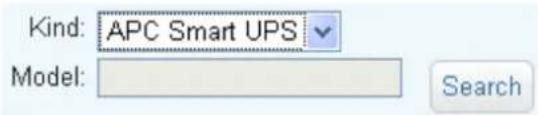 Daisy Chain: When the device is to be concatenated with the other IPM to link with the power outlet, please enable this; as for the usage and limitations of Daisy Chain, please see 2.2 Product Concatenation. Daisy Chain: When the device is to be concatenated with the other IPM to link with the power outlet, please enable this; as for the usage and limitations of Daisy Chain, please see 2.2 Product Concatenation.   |
| Data Rate | Set UART Bob rate parameter. |
| Data | Set UART bit parameter. |
| Parity | Set UART Parity Check parameter. |
| Stop Bits | Set UART stop bit parameter |
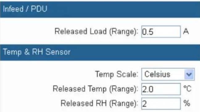
4.3.7 Peripheral Parameters
This menu is mainly for setting current, tolerance ranges of temperature and humidity, power statistics and probe as well as the panel operating, etc.
| Parameters Description | |
| Released Load (Range) | You may set up threshold current to avoid floating power triggered warning reaction. The warning will be dismissed by system when power current is lower than threshold current. |
| Temp Scale | You can choose either Celsius or Fahrenheit. |
| Released Temp. (Range) | You may set up threshold temp. to avoid floating power triggered warning reaction. The warning will be dismissed by system when temp. is lower than threshold temp. |
| Released RH (Range) | You may set up threshold RH. to avoid floating power triggered warning reaction. The warning will be dismissed by system when the humidity is lower than threshold RH. |
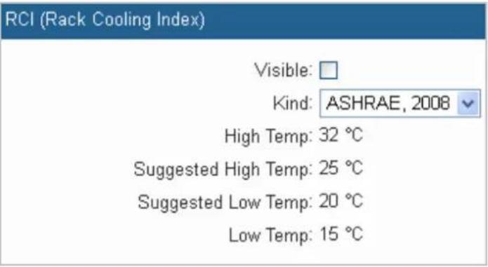
| Parameters Description | |
| Visible | Set up to display for 4.1.4 Temperature RCI blank. |
| Kind | There are three types of RCI: “NEBS, 2001”, “ASHRAE, 2004” and “ASHRAE, 2008”. |
| High Temp | Display the RCI type maximum load capacity for the temperature. |
| Suggested High Temp | Display the RCI type high capacity for the temperature. |
| Suggested Low Temp | Display the RCI type low capacity for the temperature. |
| Low Temp | Display the RCI type minimum load capacity for the temperature. |
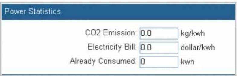
| Parameters Description | |
| CO2 Emissions | You may set up threshold current to avoid floating power triggered warning reaction. The warning will be dismissed by system when power current is lower than threshold current. |
| Temp Scale | You can choose either Celsius or Fahrenheit. |
| Released Temp (Range) | You may set up threshold temp. to avoid floating power triggered warning reaction. The warning will be dismissed by system when temp is lower than threshold temp. |
Interface Control (Elite)
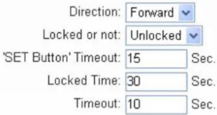
| Parameters Description | |
| Direction (only for IPM-8220) | You may set up threshold current to avoid floating power triggered warning reaction. The warning will be dismissed by system when power current is lower than threshold current. |
| Locked or not | User cannot control the switch through LED panel as it is locked. |
| "SET Button" Timeout | Use Navigation button to view LCD panel: LCD panel will show the initial picture of the first phase automatically as no operation is processing. |
| Locked Time | System will log out automatically after timeout you set as no operation is processing as LED panel stay in switch setup status. |
| Timeout | In alarm setting status: LCD panel will show the initial picture of the first phase automatically as no operation is processing. |
4.3.8 Other
This menu is mainly for setting device web page language, operation timeout and device date format.
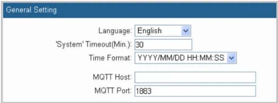
| Parameters Description | |
| Language | Traditional Chinese, Simplified Chinese and English. |
| "System" Timeout (Min) | This is the last time that the device will log out automatically with no operation in process. |
| Time Format | Choose equipment time format. There're three formats from the drag down list:YYYY/MM/DD/HH/MM/SSMM/DD/YYYY/HH/MM/SSDD/MM/YYYY/HH/MM/SS |
| MQTT Host | Enter MQTT Host IP. |
| MQTT Port | Enter Connect Port for MQTT. Default is 1883. |
Security Setting
IP Lock-up period(Min.): 30 IP Login times: 3
| Parameters Description | |
| IP Lock-up Period (Min.) | The period of such IP has been locked up. |
| IP Login Times | The number of times that user logs in. |
4.4 Firewall
In this tab, you may set up permitted IP or Mac address to access this remote power manager.

4.4.1 IP Filter
User can set up permitted IP section on this page.
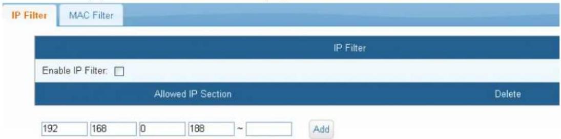
| Parameters Description | |
| Enable IP Filter | Allow authorized IP address to access this device. |
| Allowed IP Section | After keying in permitted IP section, please click ADD to implement this action. To delete a specific IP address, please click “X”. |
4.4.2 MAC filter
This menu is mainly for setting of Network MAC Address having access to this device.
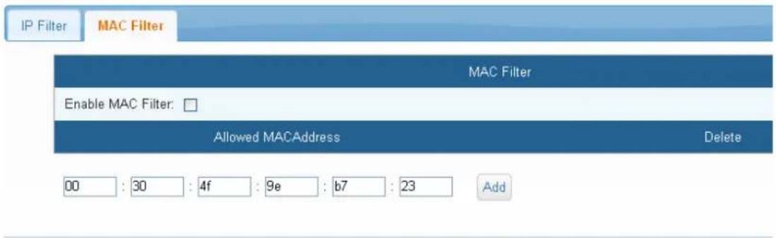
| Parameters Description | |
| Enable MAC Filter | Mark this square to enable Mac filter and press the Save button to store the setting after permitted Mac address is built. System will reject people who try to access this remote power manager from other Mac addresses. Unmark the square and press the Save button if you expect to cancel this function. |
| Allowed MAC Address | Enter permitted MAC number. Please click ADD to implement this action. To delete a specific IP address, please click “X”. |

Note
MAC blocking feature is only available for local area network; if a router is used, the original adapter MAC address may be changed.
4.5 Account
This menu allows the administrator to set up 20 sets (max) of authorized user accounts. You can Add, Modify and Delete the User account.
| Account | User Level | Modify | Delete |
| admin | Administrator | ||
| brandon | Manage | ✗ |
| Parameters Description | |
| Modify | Modify the previous setting. Operation of Alarm. |
| Delete | Click Delete icon: browser will pop up a Confirmation of delete window.Click Confirm: this Account cannot be utilized any longer. |
4.5.1 Basic Info
To set up account, password and user type.
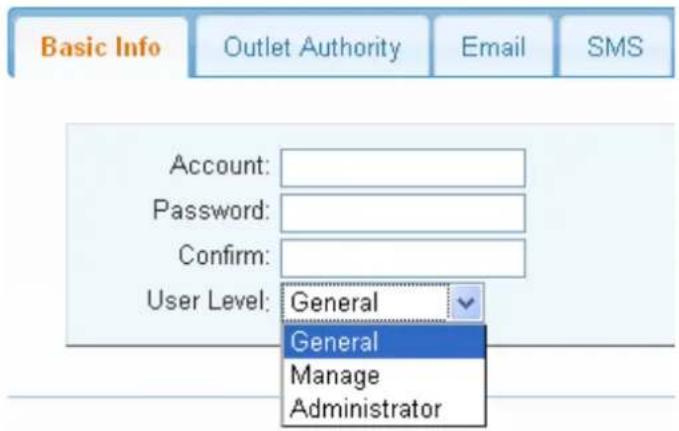
| Parameters Description | |
| Account | The account to log in to this device. |
| Password | The password to log in to this device. |
| User Level | User authority operation can be grouped into General, Manage and Administrator as shown below:General: Only Switch control is permitted, but not authorized to change system settings.Manage: Parameter setting is permitted, and controllable switch can be changed.Administrator: Administrator can manage the whole network. |
4.5.2 Outlet Authority
Outlet Authority tab is mainly to open up outlet authority to other users.

| No | Name | All |
| 1 | Port 1 | ☑ |
| 2 | Port 2 | ☑ |
| 3 | Port 3 | ☑ |
| 4 | Port 4 | ☑ |
| 5 | Port 5 | ☑ |
| 6 | Port 6 | ☑ |
| 7 | Port 7 | ☑ |
| 8 | Port 8 | ☑ |
4.5.3 Email
System would send email when alarm occurs.

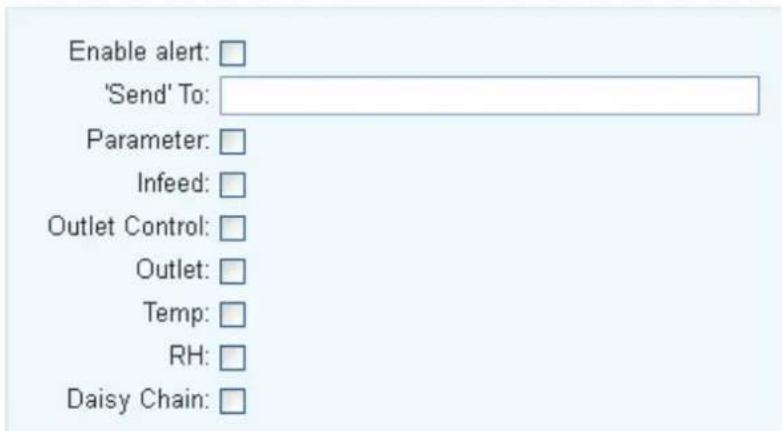
| Parameters Description | |
| Enable Alert | Check to open email alarm system informed by email. |
| ‘Send’ To | Enter the mail address of Receiver. |
| Parameter | Use the checkbox to enable the setting. The system will follow the warning method you choose. |
| Infeed | Use the checkbox to enable the setting. When abnormal condition of infeed happens, system will send a warning message by the way you command. |
| Outlet Control | Check to enable warning as abnormal condition of switch operation occurs. |
| Outlet | Check to enable warning as abnormal condition of outlet occurs. |
| Temp | Use the checkbox to enable the setting. When abnormal device temperature occurs, system will send a warning message to manager. |
| RH | Check to enable warning as abnormal condition of humidity occurs. |
| Daisy Chain | Check to enable warning as abnormal condition of concatenation occurs. |
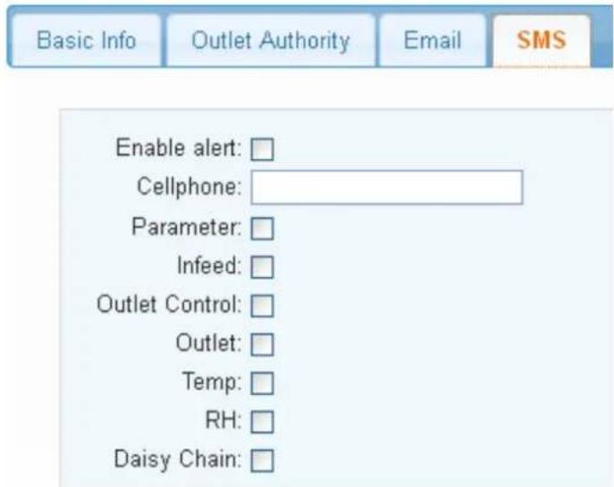
4.5.4 SMS
System would send SMS when alarm occurs.
| Parameters Description | |
| Enable Alert | Check to open email alarm system informed by SMS. |
| Cellphone | Informed by short message, please fill out the right cellphone number. |
| Parameter | Use the checkbox to enable the setting. The system will follow the warning method you choose. |
| Infeed | Use the checkbox to enable the setting. When abnormal condition of infeed happens, system will send a warning message by the way you command. |
| Outlet Control | Check to enable warning as abnormal condition of switch operation occurs. |
| Outlet | Check to enable warning as abnormal condition of outlet occurs. |
| Temp | Use the checkbox to enable the setting. When abnormal device temperature occurs, system will send a warning message to manager. |
| RH | Check to enable warning as abnormal condition of humidity occurs. |
| Daisy Chain | Check to enable warning as abnormal condition of concatenation occurs. |
4.6 Time
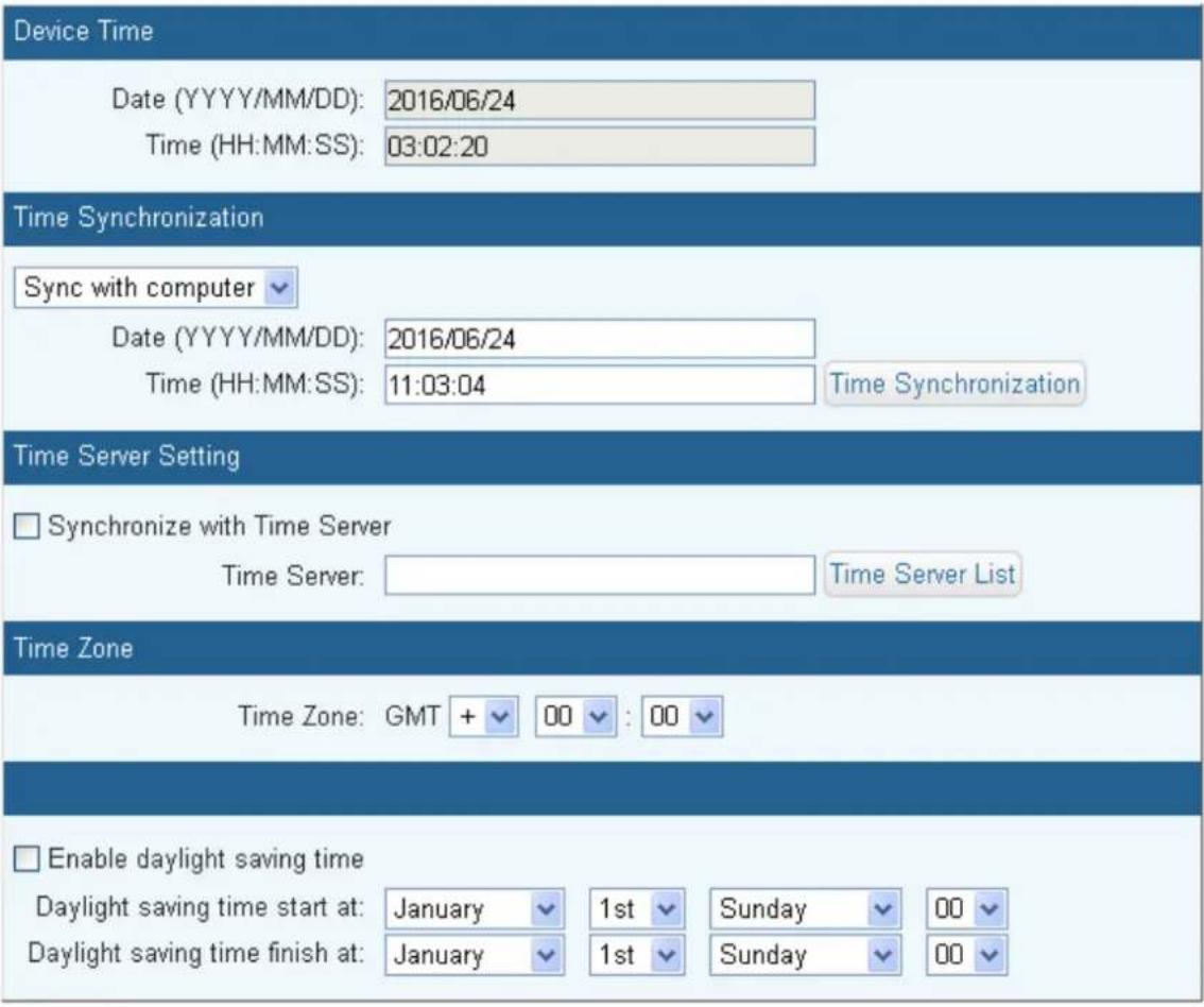
You can set up the time server on this page.
| Parameters Description | |
| Device Time | Date and time of the system. |
| Time Synchronization | You may either scroll down to select Sync with computer or Manual Setting. |
| Synchronization with Time Server | Select this time method if you want the system time of this power switch to be the same as Greenwich Mean Time (GMT). |
| Time Server | You can build a new NTP server and then sync with it to be the same date and time. If not, click Time Server List, and choose one from the drop-down list. |
| Time Zone | The time here is following Greenwich Mean Time as most NTP servers do. User must adjust the time to be the same with local time. |
Parameters Description
Enable daylight saving time
Set the Daylight saving time from Sunday to Saturday
4.7 Chart
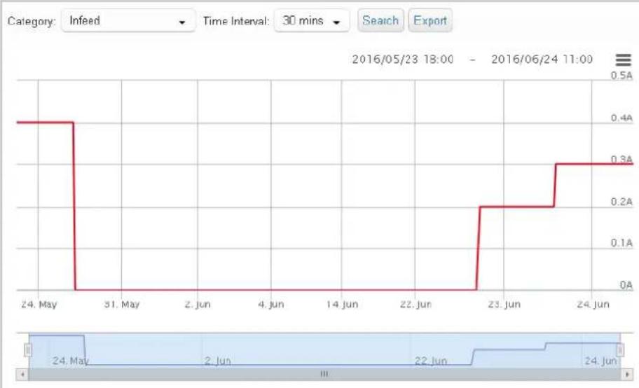
This menu is mainly for query infeed, device temperature and statistic data.
line
| Date | Value | | :--- | :--- | | 24. May | 0.4A | | 31. May | 0A | | 2. Jun | 0A | | 4. Jun | 0A | | 14 Jun | 0A | | 22 Jun | 0A | | 23 Jun | 0.2A | | 24 Jun | 0.3A | Category: Infeed Time Interval: 30 mins Search Export 2016/05/23 18:00 - 2016/06/24 11:00| Column | Value |
| Name | Loop 1 |
| Start Time | 05/23 18:00 |
| End Time | 06/24 11:00 |
| Voltage | 107 V |
| Max Current | 0.4 A |
| Min Current | 0 A |
| Average Current | 0.1 A |
| Alarm Current | 12.8 A |
| Overload Rate | 0 % |
| Average Rate | 10.8 W |
| Energy | -19.085 kWh |
| CO2 Emissions | 0 kg |
| Electricity Bill | 0 |
| Parameters Description | |
| Category | You may either scroll down to select infeed or device temperature. |
| Time Interval | You may either scroll down to select 1 min. or 30 mins. |
| Search | See the reference date chart as shown in the table. |
| Export | Download this data chart. |
4.8 Event
The web page recorded the recent 200 logs, including the time, type and message.
![Event Record Time Type Message 1 2016/06/24 10:41:23 User|admin|[192.168.0.188]login 2 2016/06/24 09:19:41 User|admin|[192.168.0.188]login 3 2016/06/23 18:20:07 User|admin|[192.168.0.188]login 4 2016/06/23 16:59:59 User|admin|[192.168.0.188]login 5 2016/06/23 15:30:15 User|admin|[192.168.0.188]login 6 2016/06/23 14:38:37 User|admin|[192.168.0.188]login 7 2016/06/23 13:11:10 User|admin|[192.168.0.188]login 8 2016/06/23 11:17:48 User|admin|[192.168.0.188]login 9 2016/06/23 11:17:08 Reboot software Page 1 of 4 View 1 - 50 of 9](/content/2026/05/900939/images/662cfc597329a4a6f62a6bf3166350d875e9420dcdc6dc4fb524038b9ccd7f01.jpg)
| Parameters Description | |
| Refresh | Click the Refresh button to refresh the screen. |
| Download | Click the Download button to save the event log information. The event log is saved in .txt format. |
| Delete | Click the Delete button to delete the Event logs. |
4.9 Upgrade
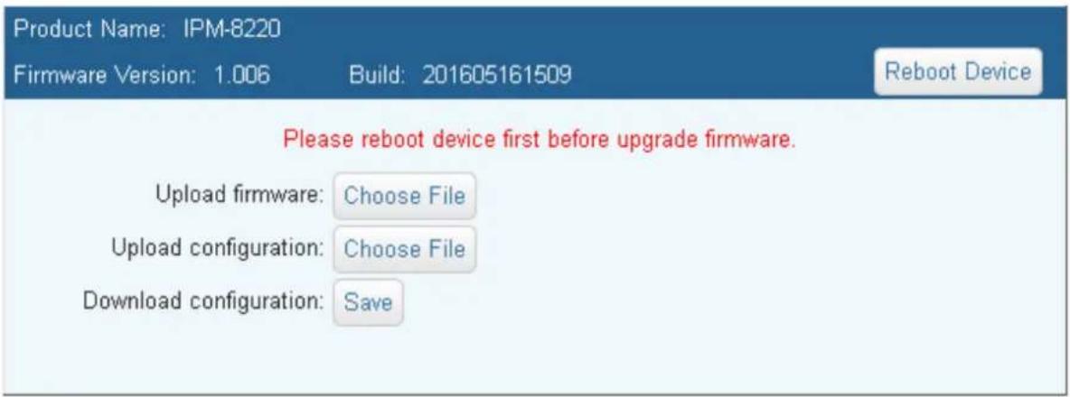
This web page is for upgrading the device firmware and the configuration files. You can download the latest firmware from the suppliers' web page to upgrade the firmware of IPM series.
| Parameters Description | |
| Upload firmware | To update the firmware online, click “Browse...” to select the firmware. Then click “Upgrade” to proceed. |
| Upload configuration | Upgrade from previous saved setting. |
| Download configuration | Download the current setting to PC. |
Chapter 5. Console Operation
In this chapter, users can learn how to operate power On/off and set the network parameters through Console. When learning console operation, users should firstly set the type of device UART1 as Console and set relevant parameters. As for the setting of UART1, please refer to 4.3.6 Serial Port (UART).
5.1 Online Set
Use the building HyperTerminal or similar programs to IPM Console; related parameter setting of terminal program Comport should be the same with UART1 set values.
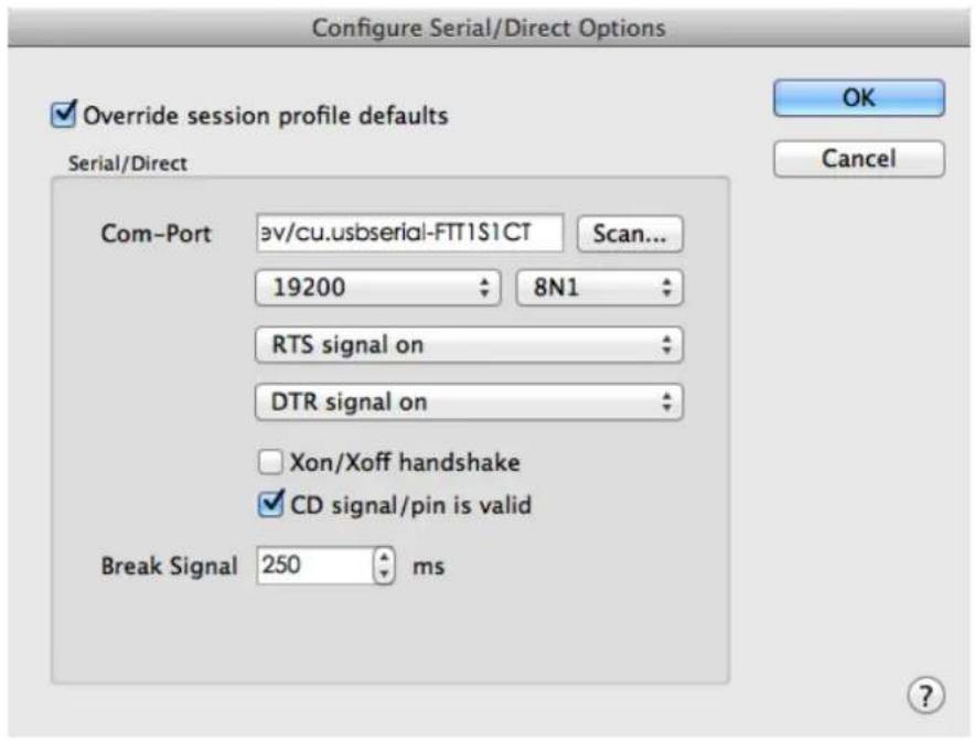
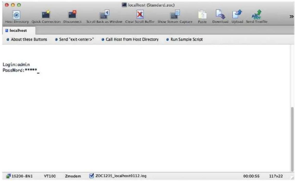
After setting is done, the HyperTerminal will display the sign-in menu; please enter the system account and password (admin and admin) established in device daemon.
After entering finished, operation menu will be displayed to control power switch and set network data.
![localhost (Standard.zoc) Host Directory Quick Connection Disconnect Scroll Back as Window Clear Scroll Buffer Show Stream Capture Paste Download Upload Send Textfile localhost About these Buttons Send "exit" Call Host from Host Directory Run Sample Script Main Menu 1.3.1 PATH> MAIN >>[OUTLET] - Outlet Ctrl [SYSTEM] - System Manager [FIREWALL] - Firewall Manager [RELOAD] - Reload Data [SAVE] - Save&Reboot [LOGOUT] - Logout [Up(^N)] [Down(^Z)] [Left(^A) - Prev Menu] [Right(^D) - Next Menu] 19200-BN1 VT100 Zmodem ZOC1205_localhost0112.log 00:01:32 117x22](/content/2026/05/900939/images/58fa8692b5c67a7248eea02c7e8658e1ce657d17df823574fea186b064f53ef5.jpg)
Operation method of the menu is as follows:
- Press ↑ or ^W can drift the menu, >> drift upward.
- Press ↓ or ^Z can drift the menu, >> drift downward.
- Press → or ^D can select the data of the next menu.
- Press ← or ^A can select the data of the precious menu.
5.2 Power Control
After selecting "OUTLET" from the main menu, press → or ^D to enter power control operation.
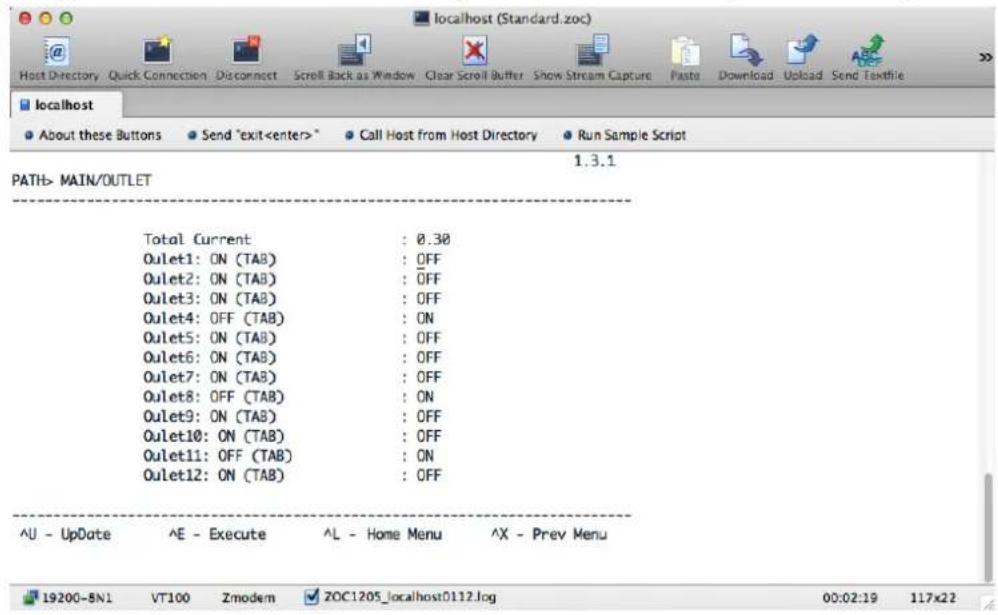
Move Up and Down keys to move the cursor to the power outlet to be operated. When the Outlet is ON, press Tab for deciding the state of this line: Reboot or Off. After selection, press "Enter" or "E" to enter the Query window to decide any operation of this outlet; if yes, press "Y"; otherwise "No".
![localhost (Standard.zoc) Host Directory Quick Connection Disconnect Scroll Back as Window Clear Scroll Buffer Show Stream Capture Paste Download Upload Send Textile localhost About these Buttons Send "exit* Call Host from Host Directory Run Sample Script Outlet[1] will REBOOT!(Y/N)_](/content/2026/05/900939/images/786a2ed18f29c3b0c56a9ac7c426242748be5a4f4735c08b869c1f591e68dba0.jpg)
5.3 System Preferences
After selecting "SYS" from the main menu, press → or ^D to enter System Preferences setting.
![localhost (Standard.zoc) Host Directory Quick Connection Disconnect Scroll Back as Window Clear Scroll Buffer Show Stream Capture Paste Download Upload Send Textfile localhost Clear Scroll Buffer About these Buttons Send "exit" Call Host from Host Directory Run Sample Script System Manager 1.3.1 PATH> MAIN/SYS >>[NetWork] - NetWork Manager [Account] - Account Manager [Up(^N)] [Down(^Z)] [Left(^A) - Prev Menu] [Right(^D) - Next Menu]](/content/2026/05/900939/images/b3428d6296546f6f7379898628c661eecc989d4009c295b91f963a2a1c1c3bd3.jpg)
5.3.1 Network Preferences
After selecting "NetWork" from the main menu, press → or ^D to enter System Preferences setting.
![localhost (Standard.zoc) Host Directory Quick Connection Disconnect Scroll Back as Window Clear Scroll Buffer Show Stream Capture Paste Download Upload Send Textfile localhost About these Buttons Send "exit" Call Host from Host Directory Run Sample Script NetWork Manager 1.3.1 PATH> MAIN/SYS/NETWORK --NetWork Setup-- DHCP(SPACE) : [ ] IP Addr : 192.168.001.024 IP Mask : 255.255.255.000 IP GateWay : 192.168.001.001 --DoName Setup-- DoName1 : 168.095.001.001 DoName2 : 000.000.000.000 --Web Setup-- Http Port : 80 Https Port : 443 Http Open(SPACE) : [X] Https Open(SPACE) : [X] ^L - Home Menu ^X - Prev Menu 19200-8N1 VT100 Zmodem ZOC1205_localhost0112.log 00:07:32 117x22](/content/2026/05/900939/images/0078e70977a3ac1db9593382119cb1a2a222ee5699fe332e396b3aa4104eaca1.jpg)
5.3.2 Account Preference
After selecting "Account" from the main menu, press → or ^D to enter System Preferences setting; this
setting is modifying the system administrator password.
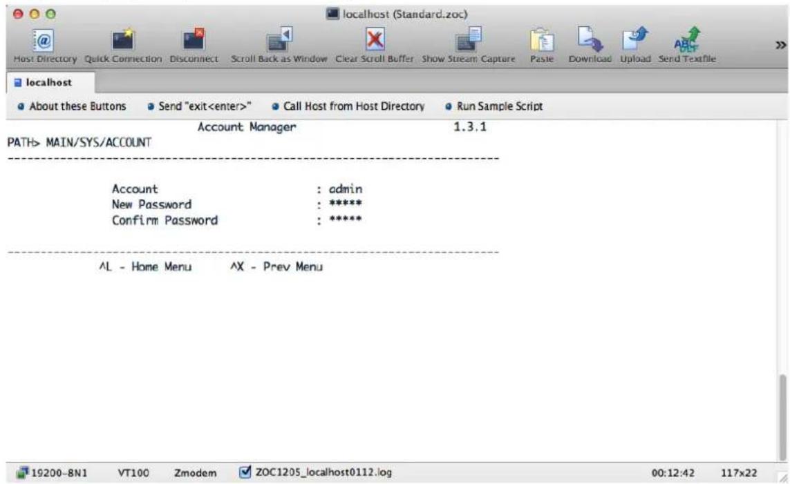
5.4 Firewall Preference
After selecting "Firewall" from the main menu, press → or ^D to enter System Preferences setting.
![localhost (Standard.zoc) Host Directory Quick Connection Disconnect Scroll Back as Window Clear Scroll Buffer Show Stream Capture Paste Download Upload Send Textfile localhost About these Buttons Send "exit" Call Host from Host Directory Run Sample Script Firewall Manager 1.3.1 PATH> MAIN/FIREWALL IP Filter(SPACE) : [] MAC Filter(SPACE) : [] ^L - Home Menu ^X - Prev Menu 19200-BN1 VT100 Zmodem ZOC1205_localhost0112.log 00:23:02 117x22](/content/2026/05/900939/images/c3f991da5ef58dff996ae49064752082c346fa14813b338bbc7d8110c50c5594.jpg)
5.5 RELOAD Preference
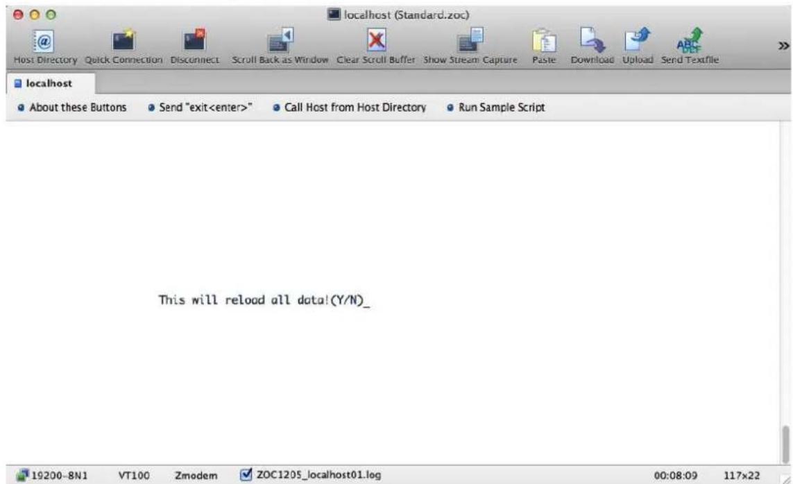
After selecting "RELOAD" from the main menu, press → or ^D to enter the query windows to reload all data; if yes, press "Y", then the device will reload network, user and firewall data, and the data revised on the terminal before canceling.
5.6 Parameter Saving
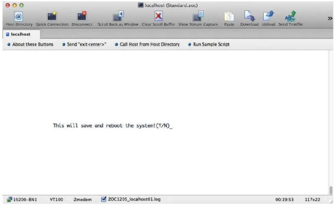
After selecting "SAVE" from the main menu, press → or ^D to enter the query windows to save and reboot the device; if yes, press "Y", then the device will save the revised data and reboot.
5.7 Logout
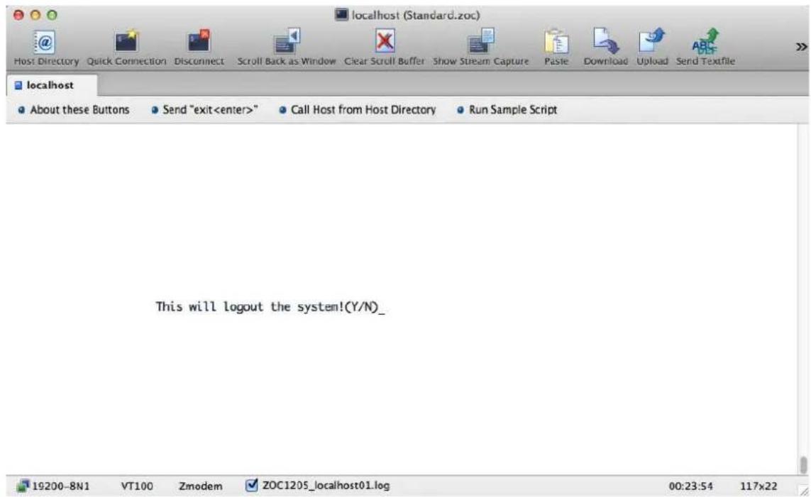
After selecting "LOGOUT" from the main menu, press → or ^D to enter the query windows; if press "Y", then the terminal program will be logged out and the sign-in menu will be displayed.
Appendix A: Resetting to Default via Reset Button
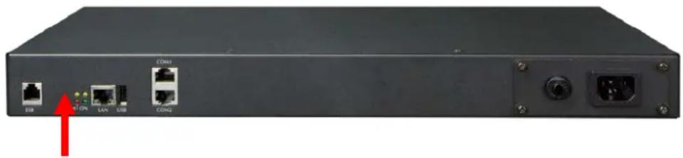
Users who forget the network account and password of the product can press "Reset" to recover to the factory default values, and the device will reboot at the same time.
Step 1. Press and hold "RESET" for more than 3 seconds. When LED starts flashing, release the hold. You are then asked fill out the admin account and password as admin (add a new account if no admin account). Device IP will be automatically acquired through DHCP (if there is no DHCP server, the device IP should be preset as 192.168.0.10). The acquired IP is displayed on the LCD panel.
Step 2. Press and hold RESET for more than 10 seconds. When LED is on, release "RESET" to clear all the data of the device.
natural_image
Front view of a black network switch device with ports and indicator lights, no visible text or symbols on the main body.| Default DHCP Client | On |
| Default IP Address | 192.168.0.10 – if no DHCP existed in the network |
| Default Port | 80 |
| Default Login User Name | Set itself |
| Default Login Password | Set itself |
| Search Tools | ip_search |
Appendix B: HTTP Message API Example
A Message API example of a message service provider is given below. The transmission mode is Get in TTP protocol, and the URL format is as follows:
http://SMLWsip/httpSMLWs.php?Tag=Value&Tag=Value&Tag=Value...
Tag variable list:
| Required | Optional Tag | Description |
| Required | depid | Company Code |
| Required | username | User's Account |
| Required | password | User's password |
| Required | dstaddr | Objective gate number (Separated by commas for delivery to multiple gate numbers, repeated gate number is not accepted during each delivery.) |
| Required | IPMbody | Message content, using standard URL encoding |
Transform the above format into message server parameters, and the menu is shown as follows:
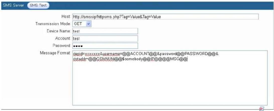
After message server setup is completed, press "Message Test" first to check if message can be sent normally.
Press the icon on the right side of the screen to see message format as a reference.
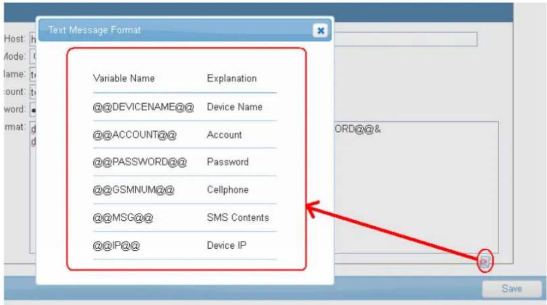
| Parameters Description | |
| @@DEVICENAME@@ | The device name will show when sending a message. |
| @@ACCOUNT@@ | The account will send the message. |
| @@PASSWORD@@ | The password will send the message. |
| @@GSMNUM@@ | The number will send the message. |
| @@MSG@@ | Message content will show when sending a message. |
| @@IP@@ | Device IP will show when sending a message. |
Message Format Explanation:
depid=xxxxxx&username=@@ACCOUNT@@&password=@@PASSWORD@@&dstaddr=@@G
SMLWNUM@@&IPMbody=@@IP@@,@@MSG@@
If you fill out the above info in the Message Format, the system would automatically show the following info:
| Message format Description | |
| Company code (depid=xxxxxx) & | Required |
| User's Account(account=@@ACCOUNT@@)& | Required |
| User's password(password=@@PASSWORD@@)& | Required |
| Cellphone number(dstaddr=@@GSMLWNUM@@)& | Required |
| Device IP & Message content(IPMbody=@@IP@@,@@MSG@@) | This format is changeable with the content. |
- IP-based 4-/8-port Switched Power Manager
- Copyright
- Federal Communication Commission Interference Statement
- FCC Caution
- Federal Communication Commission (FCC) Radiation Exposure Statement
- Safety
- CE Mark Warning
- WEEE Regulation
- Revision
- Table of Contents
- Chapter 1. Product Introduction ......6
- Chapter 2. Hardware Interface ......14
- Chapter 3. Quick Setup....24
- Chapter 4. Web-based Management....28
- Outlet Power Setup....39
- System 44
- Chapter 5. Console Operation....66
- Appendix A: Resetting to Default via Reset Button....74
- Appendix B: HTTP Message API Example 75
- Chapter 1. Product Introduction
- Package Contents
- Overview
- Meeting All Your Power Needs via IP-based Power Outlets
- Intelligent Power Management
- Electric Current Monitored on Display
- Scheduled Power On/Off
- Overload Protection
- watts
- Energy and Cost Saving
- Features
- Hardware
- Power Distribution
- Remote Access
- Management
- Security
- Chapter 2. Hardware Interface
- Physical Descriptions
- IPM-4220 Panel Operation
- IPM-8220 Current Panel Operation
- IPM-8220 Power Outlet Panel Operation
- IPM-8220 IP Panel Operation
- Product Concatenation
- Serial Port 2
- Serial Port 1
- Installation Precautions
- Hardware Installation
- Initial Utility Installation
- Chapter 3. Quick Setup
- Network Connection
- Setup Wizard
- Step 1: Language Selection
- Step 2: Account Setting
- Step 3: Host Setting
- Step 4: DNS Setting
- Step 5: Web Server
- Step 6: Time Format
- Step 7: Time Server Setting
- Step 8: Time zone
- Step 9: Daylight Saving Time
- Step 10: General Setting
- Chapter 4. Web-based Management
- Monitor
- Infeed
- Parameters Description
- Outlet (For IPM-4220)
- Outlet (For IPM-8220)
- Temperature
- RH Sensor
- Daisy Chain
- Outlet Power Setup
- Power
- Safe Shutdown
- Schedule
- Auto-Ping
- Monitor (Only for IPM-8220)
- Peripheral
- Copy
- System
- Network Setting
- Domain Name Server
- Web Server
- Firewall
- Email Server
- SMS Server
- SNMP
- Syslog
- Serial Port (UART)
- Peripheral Parameters
- Interface Control (Elite)
- Other
- Security Setting
- Firewall
- IP Filter
- MAC filter
- Account
- Basic Info
- Outlet Authority
- SMS
- Time
- Chart
- Event
- Upgrade
- Chapter 5. Console Operation
- Online Set
- Power Control
- System Preferences
- Network Preferences
- Account Preference
- Firewall Preference
- RELOAD Preference
- Parameter Saving
- Logout
- Appendix A: Resetting to Default via Reset Button
- Appendix B: HTTP Message API Example
- Message Format Explanation:
Brand : Planet
Model : IPM-8220
Category : Switch