IPM-8221 - Switch Planet - Free user manual and instructions
Find the device manual for free IPM-8221 Planet in PDF.


| Product Type | Managed PoE+ Switch |
| Model | IPM-8221 |
| Brand | Planet |
| Ports | 8 x 10/100/1000T (PoE+), 2 x SFP |
| PoE Budget | 240W (30W per port) |
| Switching Capacity | 20 Gbps |
| Dimensions (W x D x H) | 440 x 200 x 44 mm (rackmount 1U) |
| Weight | 3.2 kg |
| Power Supply | 100-240V AC, 50-60Hz, internal |
| Management | Web, CLI, SNMP v1/v2c/v3, RMON |
| VLAN Support | IEEE 802.1Q, up to 4096 VLANs |
| QoS | 8 priority queues, IEEE 802.1p, DSCP |
| Security | 802.1X, ACL, MAC filtering, DHCP snooping |
| PoE Standard | IEEE 802.3at (PoE+) and 802.3af (PoE) |
| Operating Temperature | 0°C to 50°C |
| Humidity | 10% to 90% (non-condensing) |
| Cooling | Fan, detachable on rear |
| Installation | 19-inch rackmount, desktop |
| Standards | IEEE 802.3, 802.3u, 802.3ab, 802.3z, 802.3x, 802.1D, 802.1w, 802.1s |
| Maintenance | Clean with dry cloth, avoid liquids |
| Spare Parts / Repairability | Power supply, fan replaceable; contact Planet support |
Frequently Asked Questions - IPM-8221 Planet
User questions about IPM-8221 Planet
0 question about this device. Answer the ones you know or ask your own.
Ask a new question about this device
Download the instructions for your Switch in PDF format for free! Find your manual IPM-8221 - Planet and take your electronic device back in hand. On this page are published all the documents necessary for the use of your device. IPM-8221 by Planet.
USER MANUAL IPM-8221 Planet
natural_image
Front view of a black industrial rack-mounted server unit with multiple ports and a digital display (no visible text or symbols on the device body)IP-based 8-port Switched Power Manager
with 2 Cascaded Ports
IPM-8221

natural_image
Group of business professionals in a meeting around a laptop, no visible text or symbolsCopyright
Copyright © 2024 by PLANET Technology Corp. All rights reserved. No part of this publication may be reproduced, transmitted, transcribed, stored in a retrieval system, or translated into any language or computer language, in any form or by any means, electronic, mechanical, magnetic, optical, chemical, manual or otherwise, without the prior written permission of PLANET.
PLANET makes no representations or warranties, either expressed or implied, with respect to the contents hereof and specifically disclaims any warranties, merchantability or fitness for any particular purpose. Any software described in this manual is sold or licensed "as is". Should the programs prove defective following their purchase, the buyer (and not PLANET, its distributor, or its dealer) assumes the entire cost of all necessary servicing, repair, and any incidental or consequential damages resulting from any defect in the software. Further, PLANET reserves the right to revise this publication and to make changes from time to time in the contents hereof without obligation to notify any person of such revision or changes.
All brand and product names mentioned in this manual are trademarks and/or registered trademarks of their respective holders.
Federal Communication Commission Interference Statement
This equipment has been tested and found to comply with the limits for a Class B digital device, pursuant to Part 15 of FCC Rules. These limits are designed to provide reasonable protection against harmful interference in a residential installation. This equipment generates, uses, and can radiate radio frequency energy and, if not installed and used in accordance with the instructions, may cause harmful interference to radio communications. However, there is no guarantee that interference will not occur in a particular installation. If this equipment does cause harmful interference to radio or television reception, which can be determined by turning the equipment off and on, the user is encouraged to try to correct the interference by one or more of the following measures:
- Reorient or relocate the receiving antenna.
- Increase the separation between the equipment and receiver.
- Connect the equipment into an outlet on a circuit different from that to which the receiver is connected.
- Consult the dealer or an experienced radio technician for help.
FCC Caution
To assure continued compliance, use only shielded interface cables when connecting to computer or peripheral devices. Any changes or modifications not expressly approved by the party responsible for compliance could void the user's authority to operate the equipment.
This device complies with Part 15 of the FCC Rules. Operation is subject to the following two conditions: (1) This device may not cause harmful interference, and (2) this device must accept any interference received, including interference that may cause undesired operation.
Federal Communication Commission (FCC) Radiation Exposure Statement
This equipment complies with FCC radiation exposure set forth for an uncontrolled environment. In order to avoid the possibility of exceeding the FCC radio frequency exposure limits, human proximity to the antenna shall not be less than 20 cm (8 inches) during normal operation.
Safety
This equipment is designed with the utmost care for the safety of those who install and use it. However, special attention must be paid to the dangers of electric shock and static electricity when working with electrical equipment. All guidelines of this and of the computer manufacture must therefore be allowed at all times to ensure the safe use of the equipment.
CE Mark Warning
This is a Class B product. In a domestic environment, this product may cause radio interference, in which case the user may be required to take adequate measures.
WEEE Regulation

To avoid the potential effects on the environment and human health as a result of the presence of hazardous substances in electrical and electronic equipment, end users of electrical and electronic equipment should understand the meaning of the crossed-out
wheeled bin symbol. Do not dispose of WEEE as unsorted municipal waste and have to collect such WEEE separately.
Revision
User's Manual of PLANET IP-based 8-port Switched Power Manager with 2 Cascaded Ports Model: IPM-8221
Rev: 1.00 (January, 2024)
Part No. EM-IPM-8221_v1.0
Table of Contents
Chapter 1. Product Introduction ....5
1.1 Package Contents....5
1.2 Overview....6
1.3 Features....9
1.4 Specifications....11
Chapter 2. Hardware Interface ......13
2.1 Physical Descriptions....13
2.2 Installation Precautions....15
2.3 Hardware Installation 16
2.3.1 Rack Mounting....16
2.4 Initial Utility Installation....17
2.5 PDU Discovery through PLANET NMS Controller (NMS-500/NMS-1000V) ..... 18
Chapter 3. Web Login....19
3.1 Network Connection....19
3.2 Starting Web Management ....19
Chapter 4. Web-based Management....22
4.1 Main Page / Home Page....22
4.1.1 Socket Access 23
4.1.2 Statistics....23
4.1.3 Threshold....24
4.2 Control....25
4.3 Settings 26
4.3.1 User Management 26
4.3.2 Device Deployment....29
4.3.3 Global Setting 35
4.3.4 Threshold Setting....38
4.4 About....41
4.4.1 More Warnings....42
Appendix A: Safety Instructions ....43
Appendix B: IP Address Determination....45
Chapter 1. Product Introduction
1.1 Package Contents
Thank you for purchasing PLANET IP-based Switched Power Manager, IPM-8221. "PDU" mentioned in this user manual refers to the IPM-8221.
Open the box of the Switched IPM and carefully unpack it. The box should contain the following items:
| PDU x 1 | Quick Installation Guide QR Code Sheet x 1 | Power Cord x 1 | |
| Environmental Sensor x 1 | Rack-mounting Kit x 1 | ||

If any of the above items are missing, please contact your seller immediately.
1.2 Overview
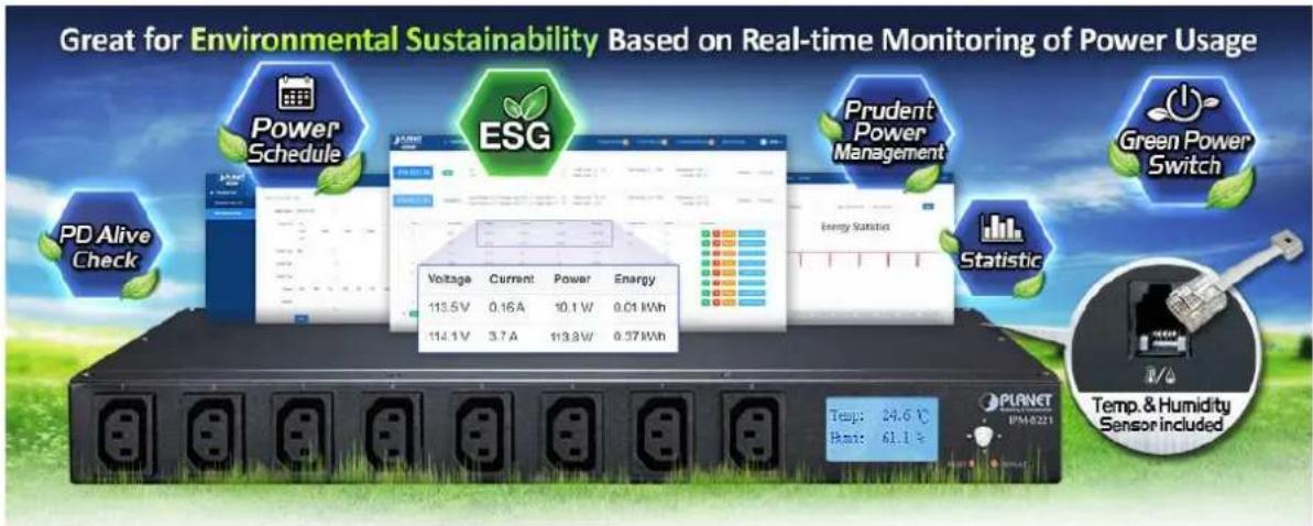
Fulfilling Your Power Requirements with IP-enabled Power Outlets Embracing ESG Principles
PLANET IPM-8221 8-port IP Power Management (IPM) device is designed to efficiently handle power distribution for a versatile array of connected devices which meet the Environmental, Social, and Governance (ESG) principles.
Leveraging cutting-edge IP-based technology, PLANET has transformed conventional power management equipment into genuine networking devices that align with sustainable and responsible business practices.
PLANET IPM-8221 can be monitored by PLANET's Universal Network Management System (UNI-NMS) and smart discovery utility to support IT staff by remotely monitoring all network devices and powered devices (PDs) while incorporating ESG considerations into the operational status assessment. This integration ensures that the device not only meets the technological needs of modern networks but also contributes to environmental sustainability, social responsibility, and robust governance in the realm of power management.
Intelligent Power Management
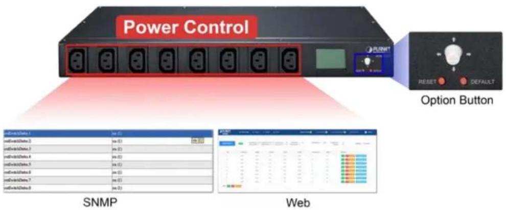
The IPM-8221 boasts 8 customizable power outlets that can be operated independently. It can monitor power usage via the SNMP, web interfaces, or the optional button to select the LCD panel display. This flexibility enables users to efficiently access, configure, and manage multiple networking devices remotely, saving valuable time and resources.
Real-time Current Monitoring
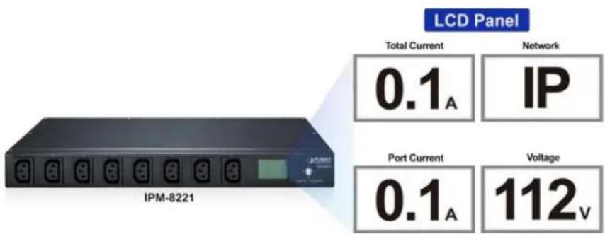
The aggregate current draw per rack PDU is displayed on the unit via a digital display. The local digital display helps installers avoid overloaded circuits by providing a visible warning when the current draw is close to the maximum amperage draw of the strip.
Scheduled Power On/Off
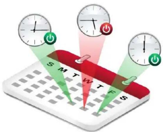
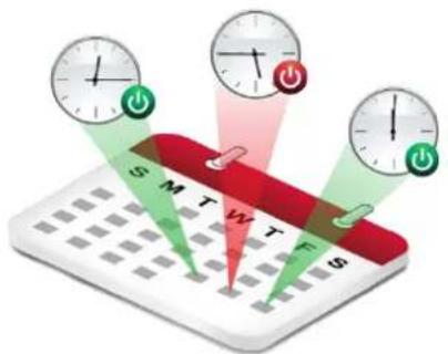
The IP-based Switched Power Manager empowers users to pre-define power schedules for IT equipment. It provides advance notice of an impending shutdown, allowing users a designated timeframe to complete tasks before the power-off sequence begins.
Enhanced Overload Protection
Unlike conventional Power Distribution Units (PDUs) that risk cutting off the entire circuit during power overload, PLANET PDU takes a proactive approach. Equipped with a built-in circuit breaker and reset switch, it ensures stable power distribution among connected equipment. The 16-amp circuit breaker acts as a safeguard against dangerous overloads, preventing potential damage to valuable equipment.
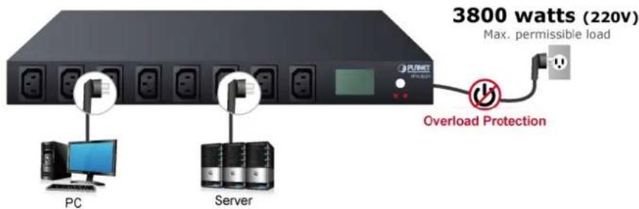
Enabling Environmental Monitoring with Precision
The IPM-8221 goes beyond power management by offering dedicated port for ambient Temperature and Humidity (T/H) sensor (sensor provided with product). This thoughtful addition allows you to seamlessly integrate environmental monitoring into your infrastructure. By connecting compatible sensor to the provided ports, you gain valuable insights into the conditions of your surroundings, ensuring optimal performance and safeguarding your equipment.
Streamlined Connectivity with Cascade Ports
Elevate your networking experience with the IPM-8221's Cascade Input/Output Port, ideal for seamlessly linking RJ45 inputs to the other one. This enables smooth integration of multiple PDUs, optimizing your network infrastructure.
Efficient Energy Management for Cost Savings
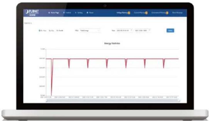
Within the configuration interface of the IPM-8221, you have the ability to monitor the current energy consumption in your office. This feature empowers you to make informed decisions to reduce energy usage, ultimately leading to significant savings on utility expenses.
line
| Date | Energy Value | | ---------- | ------------ | | 2017-03-25 | 18.0 | | 2017-04-01 | 18.0 | | 2017-04-08 | 18.0 | | 2017-04-15 | 18.0 | | 2017-04-22 | 18.0 | | 2017-04-29 | 18.0 | | 2017-05-05 | 18.0 | | 2017-05-12 | 18.0 | | 2017-05-19 | 18.0 | | 2017-05-26 | 18.0 | | 2017-06-02 | 18.0 | | 2017-06-09 | 18.0 | | 2017-06-16 | 18.0 | | 2017-06-23 | 18.0 | | 2017-06-30 | 18.0 | | 2017-07-06 | 18.0 | | 2017-07-13 | 18.0 | | 2017-07-20 | 18.0 | | 2017-07-27 | 18.0 | | 2017-08-03 | 18.0 | | 2017-08-10 | 18.0 | | 2017-08-17 | 18.0 | | 2017-08-24 | 18.0 | | 2017-09-01 | 18.0 | | 2017-09-08 | 18.0 | | 2017-09-15 | 18.0 | | 2017-09-22 | 18.0 | | 2017-09-29 | 18.0 | | 2017-10-06 | 18.0 | | 2017-10-13 | 18.0 | | 2017-10-20 | 18.0 | | 2017-10-27 | 18.0 | | 2017-11-04 | 18.0 | | 2017-11-11 | 18.0 | | 2017-11-18 | 18.0 | | 2017-11-25 | 18.0 | | 2017-12-02 | 18.0 | | 2017-12-09 | 18.0 | | 2017-12-16 | 18.0 | | 2017-12-23 | 18.0 | | 2017-12-30 | 18.0 | | 2018-01-06 | 18.0 | | 2018-01-13 | 18.0 | | 2018-01-20 | 18.0 | | 2018-01-27 | 18.0 | | 2018-02-03 | 18.0 | | 2018-02-10 | 18.0 | | 2018-02-17 | 18.0 | | 2018-02-24 | 18.0 | | 2018-03-01 | 18.0 | | 2018-03-08 | 18.0 | | 2018-03-15 | 18.0 | | 2018-03-22 | 18.0 | | 2018-03-29 | 18.0 | | 2018-04-05 | 18.0 | | 2018-04-12 | 18.0 | | 2018-04-19 | 18.0 | | 2018-04-26 | 18.0 | | 2018-05-03 | 18.0 | | 2018-05-10 | 18.0 | | 2018-05-17 | 18.0 | | 2018-05-24 | 18.0 | | 2018-05-31 | 18.0 | | 2/4/26/26 | 5.5 | | | |1.3 Features
Hardware
■ 1U rack-mount size design
IEC outlet models
■ 8 power outlets that support real-time current image monitoring
■ LCD panel displays current, voltage, energy, network and environment information
■ Optional button to lock-up protection to avoid modification
Circuit breaker can avoid damage that is caused by overload
LCD display to visually display the operating status of ports and PDU
■ Each PDU can supply a maximum load of 3800W with 255 PDUs cascaded
■ Enhanced with an environmental sensor to provide a temperature alert via email
Power Distribution
■ Maximum amps/Inlet: IEC 16A for 1 inlet
■ Maximum amps/Outlets: IEC 10A for per outlet
■ Full frequency range: 50\~60Hz
■ Individual power sockets can be controlled locally and remotely
The user can set the power on sequence and the delay time for each socket
■ Supports the current, power, and power factor detection of each power supply separately
■ Supports separate port set threshold warning and power off
Remote Access
Remote power control via TCP/IP and a built-in 10/100Mbps Ethernet port
■ Multi browsers support (Edge, Google, Firefox, Safari, Opera)
Management
Network communication protocols: TCP/IP, UDP, HTTP/HTTPS(TLS1.2), NTP, DHCP, Ping
Events notification by sending pop-up message or e-mail
■ Management Information Base (MIB) files for SNMP
■ Naming support for outlets
■ Voltage, current, wattage and total kWh report
Sets over-current watchdog for each power outlet
Activity log
■ PDU energy usage statistics
■ Zero meter clearing function
■ Firmware upgrade
■ Multiple languages
■ Displays current and voltage alarms on the home page, and queries historical records of PDU anomalies
PLANET's Universal Network Management System and Smart Discovery Utility to remotely oversee the all operational status of connected PDU
Security
■ Dynamic password verification in the login window enhances user login security verification
■ Administrator and multiple users with password protection for double-layer security
IP Filtering – Address-specific IP security masks to prevent unauthorized access
1.4 Specifications
| Product | IPM-8221 | ||
| Hardware Specifications | |||
| Outlet Power Port | 8 | ||
| Inlet Power Port | 1 | ||
| Network Connector | 1 RJ45 port for 10/100 BASE-TX | ||
| Sensor Port | 1 x RJ11-type, 6P | ||
| Cascade Port | 2 x RJ45-type | ||
| Button | 1 x Default Button1 x Reset Button1 x Interface Selection Button | ||
| LED | State of the socket / Power | LCD Displays | |
| 10/100M | 1 (Green/Orange) | ||
| LCD Panel | Displays current, voltage, energy, network and environment information | ||
| Housing | Metal | ||
| Dimensions (W x D x H) | 442 x 159 x 44.5mm | ||
| Weight | 1.84kg | ||
| Installation | 1U rack-mountable, desktop | ||
| Breaker | 1 x 16A | ||
| Power Distribution | |||
| Power | Inlet | Outlet | |
| Voltage | 100~240V | ||
| Frequency | 50~60Hz | ||
| Connection | 1 x IEC320 C20 | 8 x IEC320 C13 | |
| Maximum Current | 16A | ||
| Maximum Line Current | - | 10A | |
| Management | |||
| User Account | Operator/Visitor | ||
| Management / Monitor Utility | Web browser, SNMPPLANET Universal Network Management SystemPLANET Smart Discovery Utility | ||
| Security | IP filter | ||
| Standards Conformance | |
| Computer Interface | IEEE 802.3 10BASE-TIEEE 802.3u 10/100BASE-TX |
| Regulatory Compliance | CE, FCC |
| Environments | |
| Operating Temperature | 0 ~ 60 degrees C |
| Operating Humidity | 0 ~ 90% |
Chapter 2. Hardware Interface
2.1 Physical Descriptions
Front Panel
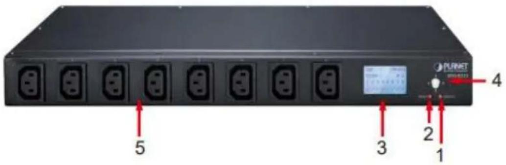
| No. | Item | Description |
| 1 | Default Switch | This switch is recessed and must be pushed with a thin object, such as the end of a paper clip.You can press this button and hold it formore than 3 seconds to reset the PDU to factory default values.Release this switch and restart the device to take effect. |
| 2 | Reset Switch | Hold down the key to restart the PDU. |
| 3 | LCD Displays | LCD is used to display PDU status information. |
| 4 | Interface Selection Button | Used to control the menu function of LCD. |
| 5 | Power Output Socket | Each power socket can connect to electrical devices with the current less than 10A.The total output power is less than 16A. If the power output exceeds the maximum load, the PDU and electrical devices may be damaged and the circuit breaker protection function may be |
Rear Panel
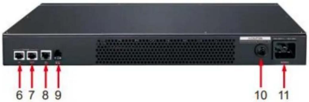
| No. | Item | Description |
| 6 | Cascade Input Port | Cascaded RJ45 input to other PDUs. |
| 7 | Cascade Output Port | Cascaded output with other PDUs through RJ45. |
| 8 | LAN Port | It can connect to 10M/100M Ethernet network. Control and access PDUs. |
| 9 | T/H Sensor Ports | External temperature and humidity sensors can be connected through RJ11 ports. |
| 10 | Overload Protection Switch | When the PDU is overloaded, the protector automatically disconnects the power supply to protect the electrical equipment. |
| 11 | 16A Power Input Socket | Please plug the power cable into the AC power supply here. This power input socket is equipped with a switch setting. When the power cable is connected and the power switch is turned on, the PDU can be put into working state. |
2.2 Installation Precautions
- Please set the maximum power-off protection allowed by power circuit as per the rated current information indicated on the device with reference to the local state rules, safety procedures and disconnection or deviation.
■ The unit can only be connected to a grounded power outlet or system.
■ Make sure the total current output of all the connected systems is within the rated current indicated on the device.
■ The test results of this device may be inaccurate giving unstable power supply. - Avoid using this device in places near water or moisture environments.

In order to avoid a fire hazard or risk of electric shock, do not expose the product to rain or moisture.
■ Use the attachments/accessories specified by the manufacturer only.
- Please avoid any items or liquids entering the device because their contact with dangerous voltage points or short-circuit parts may cause a fire or electric shock.
2.3 Hardware Installation
A PDU can be installed in an indoor distribution box or on a wall. To install a PDU in the above positions, use the fasteners and screws delivered with the DEVICE to secure the PDU to a specific position.
To install a PDU, perform the following operations:
Step 1. Properly ground the PDU using ground cables. Connect one end of the grounding cable to the grounding terminal and the other end to the appropriate grounding object.
Step 2. For each group of devices to be connected, use their power cables to connect the AC socket of the device to the available socket on the PDU.
Step 3. Connect the cable that connects the PDU to the network connection port of the PDU.
Step 4. Connect the PDU power cable to the AC power supply.
After connecting PDUs, power on PDUs and connected devices.

-
Do not omit Step 1. Proper grounding can avoid damage caused by surge or static electricity.
-
Do not plug the PDU power cord into the extender of multiple sockets to prevent it from being unable to get enough power to operate properly.
-
It is strongly recommended that you use harness straps and cable boxes to secure cables to the front panel of the equipment. Prevent loose and poor contact in subsequent time.
-
Please make sure all the units connected are powered off before the installation of the device and take other necessary precautions during the installation.
2.3.1 Rack Mounting
Please note the following items when performing rack installation.
- When extending the device out of the rack, ensure that the rack is smooth and stable.
- Do not overload the AC branches that supply power to the frame; the carrying capacity of the whole frame should not exceed eighty percent of the power of the branch.
- Make sure that all equipment used on the rack – including power strips and other electrical connectors – is properly grounded.
- Ensure that proper airflow is provided to devices in the rack.
- Ensure that the operating ambient temperature of the rack environment does not exceed the maximum ambient temperature specified for the equipment by the manufacturer
- Do not step on or stand on any device when servicing other devices in a rack.
2.4 Initial Utility Installation
PLANET "Smart Discovery" is a software utility used to search the IP Metered PDU product on a network quickly and with ease.
Step 1: Please download the Smart Discovery tool from PLANET Download Center.
Step 2: Please press the "Refresh" button to find out your IP Metered PDU.
natural_image
Abstract geometric design with overlapping triangles and a rectangular block containing three horizontal lines (no text or symbols)
Note
- Before searching the IP, please make sure your PC is in the same IP segment as control gateway.
- Do not set double IP addresses on the same LAN card.
Step 3: Enter the IP address and log in to the homepage of IPM.
2.5 PDU Discovery through PLANET NMS Controller
(NMS-500/NMS-1000V)
The IPM-8221 is the IP-based Switched Power Manager which can be centrally monitored by PLANET NMS Controller.
Follow the steps below to discover the managed PDU through PLANET NMS controller
(NMS-500/NMS-1000V). Please ensure NMS and each managed PDU use a different static IP in the same subnet before physically connecting to the managed network.

Please regularly check PLANET website for the latest compatible list of the controller/managed PDUs in each firmware version.
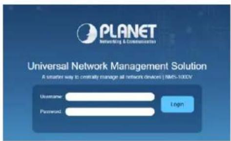
| Step 1: | Launch the Web browser (Google Chrome is recommended.) and enter the default IP addresshttps://192.168.1.100:8888of the NMS controller. Then, enter the default username and password “admin” to log on to the system.*The secure login with SSL (HTTPS) prefix is required. |
| Step 2: | Go to the “Domain” page to discover and add the managed PDU to the device list. Then, you can search and go to the “Device List” and “Topology View” page to monitor the managed PDU. |

Chapter 3. Web Login
In this section users can learn how to query device IP and how to set language, account password, network and time zone through daemon.
3.1 Network Connection
After the device is connected to the network, the device IP will be preset to 192.168.0.10. The IP can be displayed on the LCD panel or device IP can be searched by PLANET Smart Discovery.
| Default DHCP Client | Off |
| Default IP Address | 192.168.0.10 |
| Default Port | 80 |
| Default Login User Name | Admin |
| Default Login Password | admin |
| Search Tools | PLANET Smart Discovery |
3.2 Starting Web Management
Step 1: Log in the web setting page of PDU
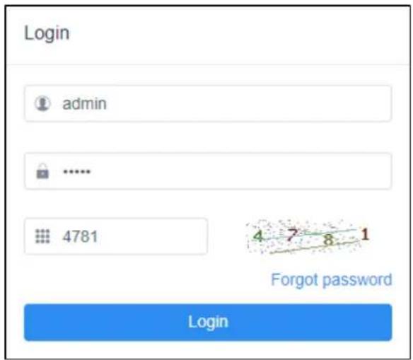
Enter the IP address of PDU (e.g., https://192.168.0.10) in the address bar using the https method of your PC's web browser. The login screen in Figure 3-2-1 appears.
The default user name and password are both admin.
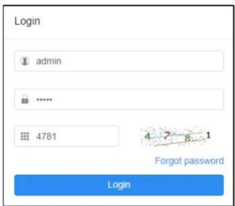
Figure 3-2-1 Login screen
For security reasons, you must change to your unique user name and password (See Step 4. Changing Administrator Log-in for more information).
Step 2: After you have logged in to the PDU successfully, the Socket Access/Connection page will appear:
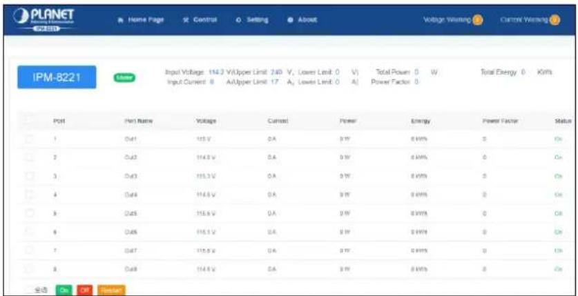
Figure 3-2-2 Default Main Page
After logging in, the top panel of the page provides the following options for PDU operations: Home Page, Control, Statistics, Settings, and About. Click the corresponding TAB to select, set, and view the functions provided on the corresponding page.
Step 3: Network Configuration
To configure the network, perform the following operations:
- Click the Setting TAB.
- The device configuration page is displayed. A screen similar to the following should appear:

User Management
Duan List
Add User
Permission Management
Blackfoot Setting

Device Deployment
Cascada Sarling
Network Setting
Port Name Setting
Port Delay Setting
SNMP S-rio
Ping Setting

Global Setting
Mail Settlement
System Time Setting
Clear Energy
Restore to Factory Setting
Upgrade
Language Setting

Threshold Setting
input Warning Setting
Output Warning Setting
Output Off Setting
Temp & Hum! Warning Setting
Figure 3-2-3 Configuration Page
- Please fill in the field data according to the information provided in the device setting instructions of Network Setting.
Step 4. Change of administrator Log-in
To change the default user name and password of the administrator, perform the following operations:
- Click the User List in the User Management button at the top of the screen. The User List screen in Figure 3-2-4 appears. A list of users is listed on the left side of the user administrator page, with their more detailed information displayed on a large block in the center.
2.
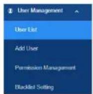

Figure 3-2-4 User List Page
In the Administrator information section, select Edit to reset the unique name and password, then click Save (bottom of the page).
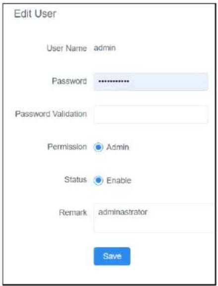
Figure 3-2-5 Edit User Page
- After you complete the network settings and change the default administrator account and password, you can grant operational permissions to other administrator accounts. Instructions for managing new users are explained in the next section.

If you forget the administrator account and password, please reset the PDU to restore the initial settings and the default administrator account.
Chapter 4. Web-based Management
This section provides instructions about how to use the web interface to configure and control the IP Power Manager remotely.
4.1 Main Page / Home Page
Once you have logged in successfully, the PDU home page will appear as shown below along with the socket access page:
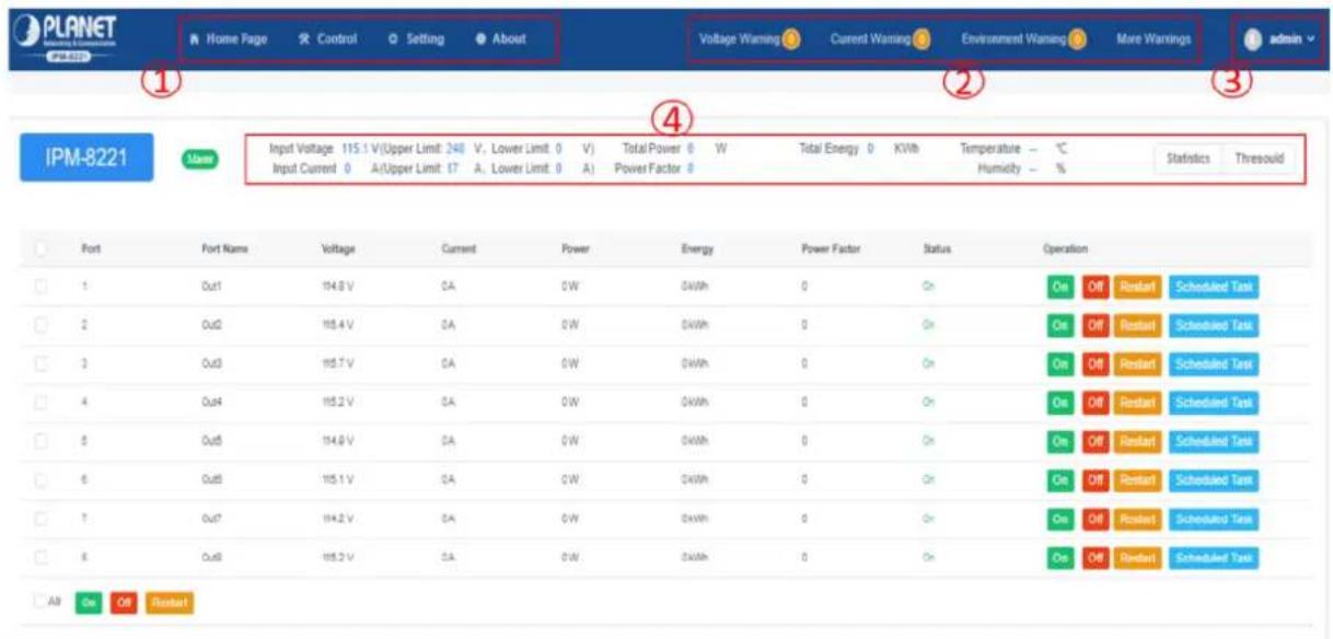
Figure 4-1-1 Home Page Screenshot
■ Page Components
Web page components are described as follows:
| No. | Item | Description |
| 1 | Option Column | This option column contains the main operation categories of THE PDU. The items that appear in the option column vary according to the user type. This authorization option is set when the account is established. |
| 2 | Alarm Column | Lists the number of alarms related to the PDU running process. You can click to go to the details page to view the type and content of the alarm。 |
| 3 | Log-in Options | You can perform log-in operations, such as refreshing, logging out, changing passwords, and querying logs。 |
| 4 | PDU Operating Status | Provides real-time information about the device, such as power voltage, current, power consumption, and temperature/humidity. |
4.1.1 Socket Access
When you log in to the PDU, the user interface will be displayed with the default socket access page and a menu. The PDU status and socket status contents are displayed on the main block.
| Port Name | Voltage | Current | Power | Energy | Power Factor | Status | Operation | |||
| Out1 | 115.7 V | 0A | 0W | 0 kWh | 0 | On | On | Off | Restart | Scheduled Task |
| Out2 | 117.2 V | 0A | 0W | 0 kWh | 0 | On | On | Off | Restart | Scheduled Task |
| Out3 | 117.6 V | 0A | 0W | 0 kWh | 0 | On | On | Off | Restart | Scheduled Task |
| Out4 | 117.3 V | 0A | 0W | 0 kWh | 0 | On | On | Off | Restart | Scheduled Task |
| Out5 | 118.7 V | 0A | 0W | 0 kWh | 0 | On | On | Off | Restart | Scheduled Task |
| Out6 | 118.0 V | 0A | 0W | 0 kWh | 0 | On | On | Off | Restart | Scheduled Task |
| Out7 | 118.2 V | 0A | 0W | 0 kWh | 0 | On | On | Off | Restart | Scheduled Task |
| Out8 | 117 V | 0A | 0W | 0 kWh | 0 | On | On | Off | Restart | Scheduled Task |
Figure 4-1-2 Socket Access Page Screenshot

Only PDUs with this function display the socket status sub-menu block. Other models only provide PDU status monitoring, which allows you to enable, disable, reset, and schedule tasks for corresponding port sockets. For detailed descriptions, refer to the subsequent chapters.
4.1.2 Statistics
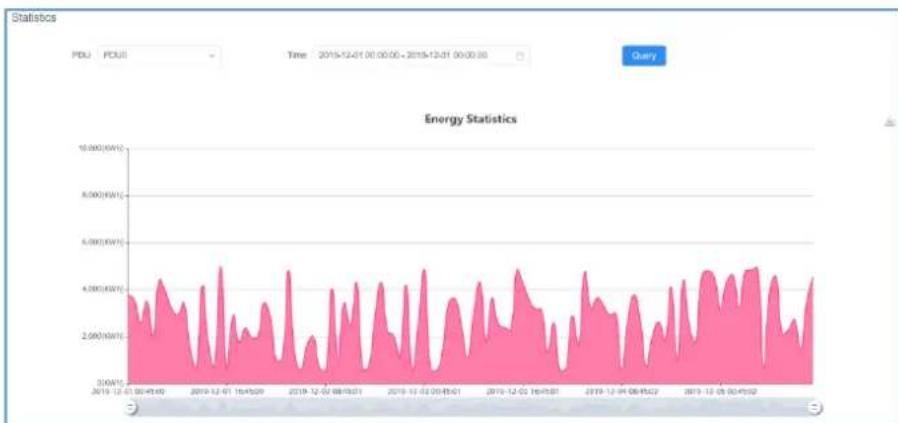
You can collect energy consumption statistics based on the specified query time range. Select a start time from the drop-down list box based on the date, month, and year. You can select energy consumption within 24 hours, the latest 7 days, 30 days, and 90 days based on the quick selection function on the time bar.
line
| Date | Energy (kWh) | | ---------- | ------------ | | 2019-12-01 | 3.5 | | 2019-12-07 | 4.2 | | 2019-12-14 | 3.8 | | 2019-12-21 | 4.5 | | 2019-12-28 | 3.6 | | 2019-1-04 | 4.0 | | 2019-1-11 | 3.9 | | 2019-1-18 | 4.3 | | 2019-1-25 | 4.1 | | 2019-2-02 | 3.7 | | 2019-2-09 | 4.4 | | 2019-2-16 | 3.8 | | 2019-3-02 | 4.6 | | 2019-3-09 | 4.0 | | 2019-3-16 | 3.9 | | 2019-3-23 | 4.2 | | 2019-4-00 | 4.5 | | 2019-4-07 | 3.7 | | 2019-4-14 | 4.3 | | 2019-4-21 | 4.1 | | 2019-4-28 | 3.8 | | 2019-5-05 | 4.4 | | 2019-5-12 | 4.6 | | 2019-5-19 | 3.9 | | 2019-5-26 | 4.2 | | 2019-6-03 | 4.5 | | 2019-6-10 | 4.0 | | 2019-6-17 | 3.8 | | 2019-6-24 | 4.3 | | 2019-7-01 | 4.7 | | 2019-7-08 | 4.1 | | 2019-7-15 | 3.7 | | 2019-7-22 | 4.4 | | 2019-7-29 | 4.6 | | 2019-8-06 | 4.0 | | 2019-8-13 | 3.8 | | 2019-8-20 | 4.5 | | 2019-8-27 | 4.8 | | 2019-9-04 | 4.3 | | 2019-9-11 | 3.9 | | 2019-9-18 | 4.4 | | 2019-9-25 | 4.7 | | 2019-10-02 | 4.1 | | 2019-10-09 | 3.8 | | 2019-10-16 | 4.5 | | 2019-10-23 | 4.6 | | 2019-10-30 | 3.7 | | 2019-11-07 | 4.3 | | 2019-11-14 | 4.7 | | 2019-11-21 | 4.0 | | 2019-11-28 | 3.8 | | 2019-12-05 | 4.4 | | 2019-12-12 | 4.6 | | 2019-12-19 | 4.0 | | 2019-12-26 | 3.7 | | 2019-1/3 | 4.5 | | 2019-1/10 | 4.8 | | 2019-1/17 | 4.3 | | 2019-1/24 | 3.9 | | 2019-2/01 | 4.5 | | 2019-2/08 | 4.7 | | 2019-2/15 | 4.0 | | 2019-3/6 | 3.8 | | 2019-3/7 | 4.6 | | 2019-3/8 | 4.8 | | 2019-3/9 | 4.3 | | 2019-3/16 | 3.7 | | 2019-3/23 | 4.4 | | 2019-3/30 | 4.7 | | 2019-4/6 | 4.0 | | 2019-4/7 | 3.8 | | 2019-4/8 | 4.5 | | 2019-4/9 | 4.6 | | 2019-5/6 | 3.7 | | 2019-5/7 | 3.8 | | 2019-5/8 | 4.5 | | 2019-5/9 | 4.7 | | 2019-6/6 | 4.0 | | 2019-6/7 | 3.8 | | 2019-6/8 | 4.6 | | 2019-6/9 | 4.8 | | 2019-7/6 | 4.3 | | 2019-7/7 | 3.7 | | 2019-7/8 | 4.5 | | 2019-7/9 | 4.7 | | 2019-8/6 | 3.8 | | 2019-8/7 | 3.7 | | 2019-8/8 | 4.5 | | 2019-8/9 | 4.6 | | 2019-9/6 | 3.7 | | 2019-9/7 | 3.8 | | 2019-9/8 | 4.5 | | 2019-9/9 | 4.7 | | 2019-10-6 | 3.8 | | 2019-10-7 | 3.7 | | 2019-10-8 | 4.5 | | 2019-10-9 | 4.6 | | 2019-11-6 | 3.7 | | 2019-11-7 | 3.8 | | 2019-11-8 | 4.5 | | 2019-11-9 | 4.7 | | Note: The actual values are not provided in the code provided in the code image. The code contains a placeholder for the actual values that would be generated by the OCR result for the year ended December of each year.Figure 4-1-3 Energy Statistics Page Screenshot

The power consumption statistics chart can only display the currently connected PDU. When the Master PDU is connected to the Slave PDU using the cascade function, only the Master PDU will be displayed on the statistical web page of the Master PDU. To view the power consumption statistics of the Slave PDU, you will need to check it on the respective Slave PDU.
4.1.3 Threshold
Click the Threshold button in the Home Page at the top of the screen. The Socket Threshold Setting screen in Figure 4-1-4 appears. You can set the maximum and minimum values of the input current to each socket. When the current exceeds the threshold, the PDU automatically sends alarm logs to the specified email box address, and an alarm message is displayed on the home page, or automatically disconnects the corresponding port to eliminate the risk of device overload. After the modification, click the Save button to save the settings. Please refer to the 4.3.4 chapter for more detail.
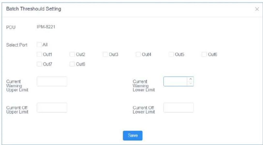
Figure 4-1-4 Socket Threshould Setting Page Screenshot
4.2 Control
On the menu bar of the home page, select Control to access the scheduled task options page of the PDU. You can query scheduled tasks and add new scheduled tasks for the socket.

Figure 4-2-1 Scheduled Tasks List Page Screenshot
In the schedule task list bar, you can retrieve the desired port schedule status by time.
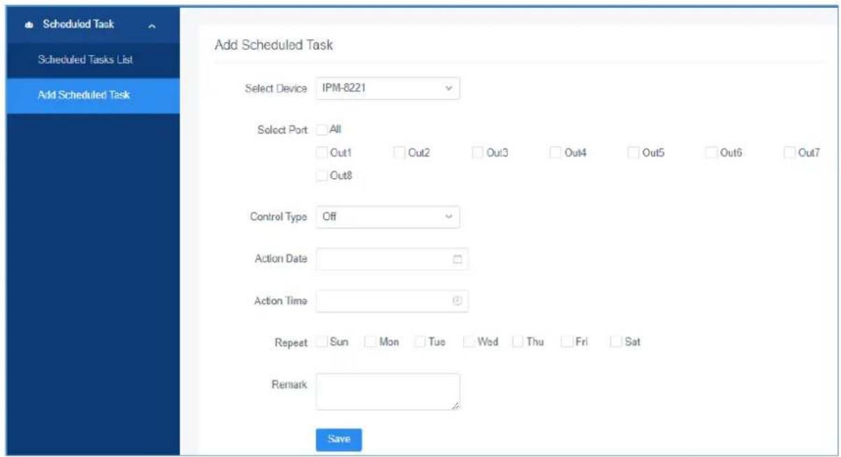
Figure 4-2-2 Add Scheduled Task Page Screenshot
In addition, scheduled task TAB, you can add scheduled tasks based on your requirements, such as socket port, switch type, time, working day, and remarks. Select the corresponding option and click the Save button to save and generate a scheduled task. PDU will perform the corresponding scheduled task operation at the set time.
4.3 Settings
Setting options includes User Management, Device Deployment, Global Setting, and Threshold Setting. This option is available only to administrators. Common users cannot see this option.
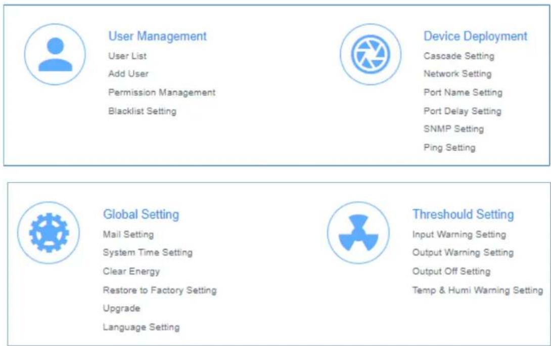
Figure 4-3-1 Configuration Page
4.3.1 User Management
Sub-function options include User List, Add User, Permission Management, and Blacklist Setting.
■ User List
If you log in to the PDU as an administrator, the account list displays information about all accounts in the PDU system. The administrator has the permission to add, delete, and edit accounts. The default administrator account can only be edited but cannot be deleted.
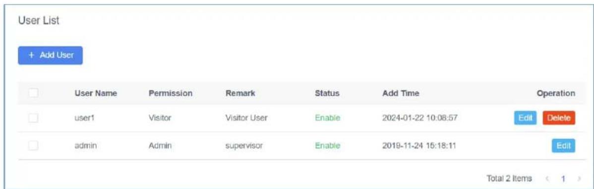
Figure 4-3-2 User List Page Screenshot
■ Add User
After logging in as an administrator, you can use this function to add new accounts and select corresponding permissions.
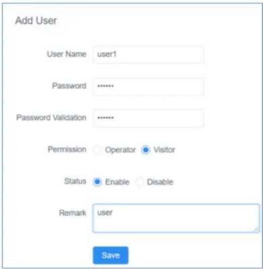
Figure 4-3-3 Add User Page Screenshot
■ Permission Management
There are two levels of permission management options: Operator and Visitor. Operator rights provides functions related to PDU operations. If selected, the corresponding rights take effect and the operator is granted the operation rights.
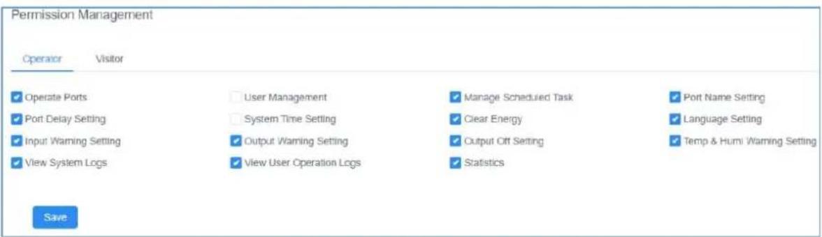
Figure 4-3-4 Permission Management Page Screenshot - Operator
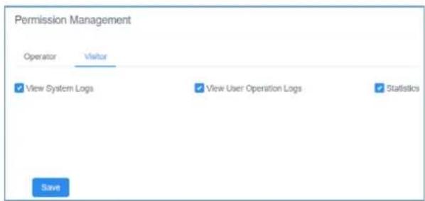
Figure 4-3-5 Permission Management Page Screenshot - Visitor
Visitor permission- This section describes how to query system logs, operation logs, and statistics. You can select the corresponding options to assign the browsing permission to users.
■ Blacklist Setting
Users can add Settings based on the IP addresses that need to be restricted to prevent accounts with restricted addresses from accessing and logging in to the PDU control system.
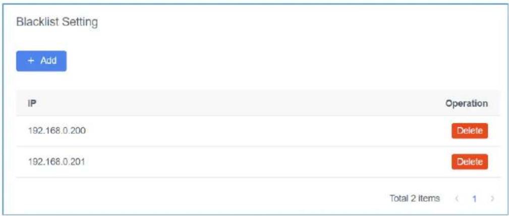
Figure 4-3-6 Blacklist Setting Page Screenshot
4.3.2 Device Deployment
Sub-function options include Cascade Setting, Network Setting, Port Name Setting, Port Delay Setting, SNMP Setting and Ping Setting.
■ Cascade Setting
The cascade feature allows the connection of other IPM-8221 PDUs. Users only need to access the web page of the Master PDU to centrally manage all connected IPM-8221 PDUs.
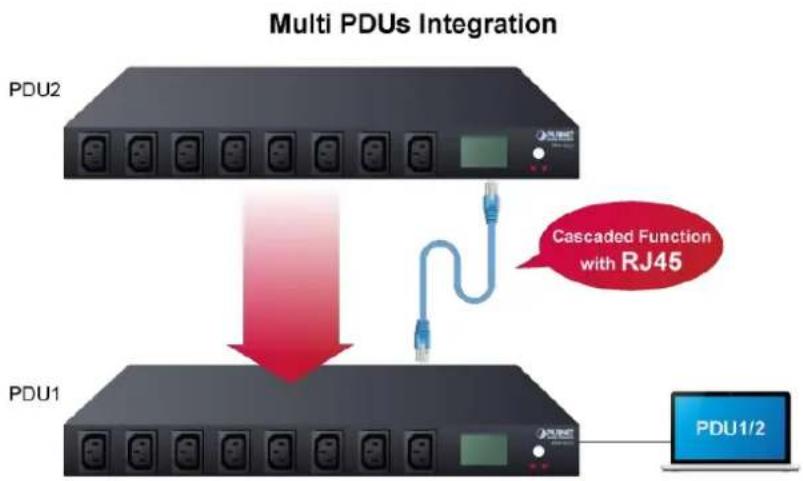
flowchart
graph TD
    A["PDU1"] -->|Cascaded Function with RJ45| B["PDU2"]
    B --> C["Computer PDU1/2"]
Please following the steps as below for example.
Step 1. Choose a PDU to serve as the Master role and select the total number of slave PDUs.
Additionally, set specific and unique addresses for each slave PDU. After the modification, click the Save button to save the settings, then please restart the system to apply the changes.
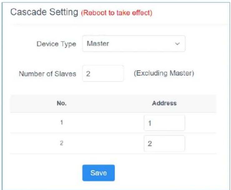
Figure 4-3-7 Cascade Setting for Master Page Screenshot
Step 2. Individually go to each Slave PDU to configure the corresponding address.
After the modification, click the Save button to save the settings, then please restart the system to apply the changes.
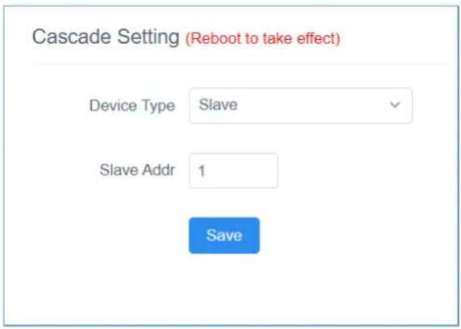
Figure 4-3-8-1 Cascade Setting for Slave Page Screenshot
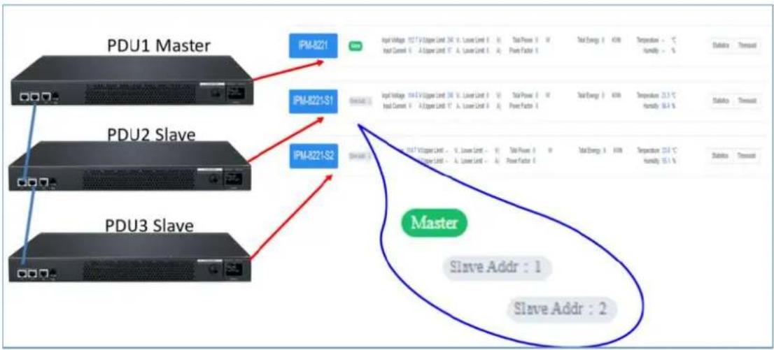
Step 3. Use a RJ45 UTP cable to connect the cascade IN port of the Slave PDU from the cascade OUT port of the Master PDU for establishing the connection between the Master PDU and Slave PDU and so on. Then there are two Slave PDUs status will be displayed on the Master PDU web page as below for example with two Slave PDUs connection.
flowchart
graph TD
    A["PDU1 Master"] --> B["IPM-821"]
    C["PDU2 Slave"] --> D["IPM-8221-S1"]
    E["PDU3 Slave"] --> F["IPM-8221-S2"]
    B --> G["Master"]
    D --> G
    F --> G
    G --> H["Slave Addr : 1"]
    G --> I["Slave Addr : 2"]
Figure 4-3-8-2 Master PDU Home Page After Cascade Setting Screenshot
■ Network Setting
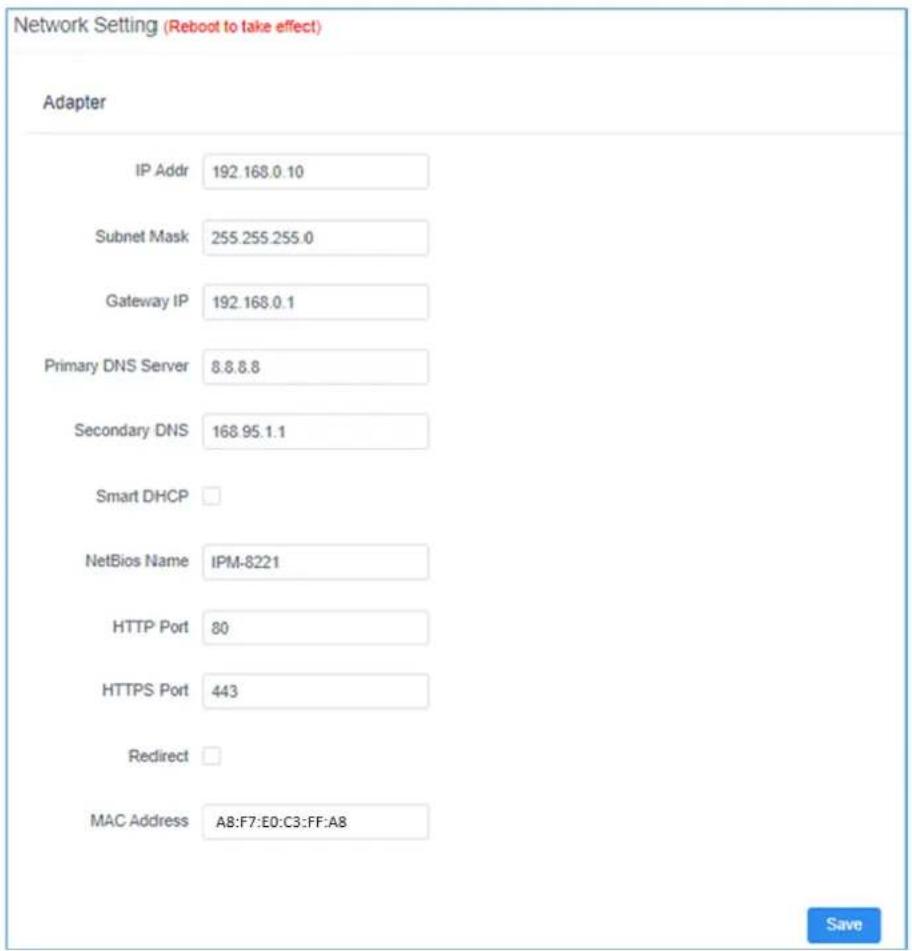
Figure 4-3-9 Network Setting Page Screenshot
The default IP address is 192.168.0.10. You can reset the IP address and network settings based on your IP address segment. Click Save to save the new Settings. After setting the parameters, please restart the system to apply the changes.
By default, the Redirect option is disable. In this case, PDUs support http or https. If this option is enable, PDUs can only support https access.
By default, the smart DHCP option is disable. In this case, you need to set the IP address of the PDU. If this option is enable, the PDU changes to dynamic IP address assignment mode.

You can restart the PDU in two ways:
- Press the embedded RST reset button at the front of the PDU with a needle, such as the end of a paper clip, to restart the PDU.
- On the Web page of the PDU, select the Upgrade option in Global Setting and click Restart to restart the device.
■ Port Name Setting
Click the Port Name Setting. The User List screen in Figure 4-3-10 appears. You can set the name of the PDU or the socket of the PDU control port. After the modification, click the Save button to save the settings.
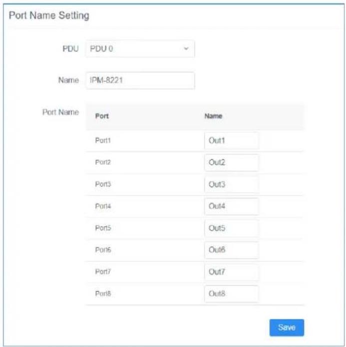
Figure 4-3-10 Port Name Setting Page Screenshot
■ Port Delay Setting
Port delay setting function allows you to set the opening and closing delay time of the port socket. By default, the switching interval of the adjacent port is 1 second. You can also modify the interval delay time according to your needs. After the modification, click the Save button to save the settings.
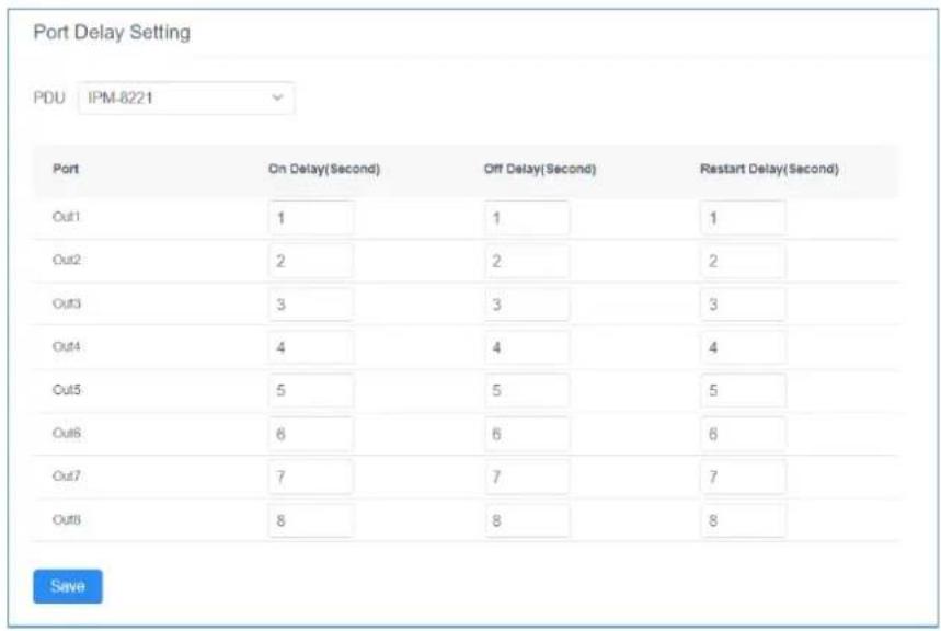
Figure 4-3-11 Port Delay Setting Page Screenshot

The delay time of the port socket is intended to protect the electrical appliance from experiencing the shock of current and voltage at the moment of power-on, thus protecting the electrical appliance from damage. It is strongly recommended to retain the default delay setting.
■ SNMP Setting
By default, the SNMP function is disable. If this function is enabled, you can manage the PDU via SNMP tool. The message will be sent to SNMP management when the circuit breaker traps or the PDU socket threshold is set beyond the minimum or maximum setting range. After the modification, click the Save button to save the settings, then please restart the system to apply the changes.
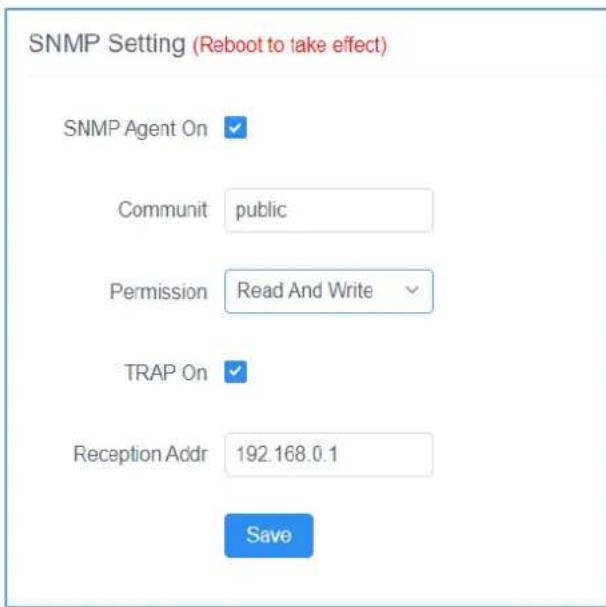
Figure 4-3-12 SNMP Setting Page Screenshot
■ Ping Setting
Ping Setting is used to test whether the network of the port connected to the PDU is normal. You can set an IP address and interval to test whether the network is normal. After the modification, click the
Save button to save the settings.
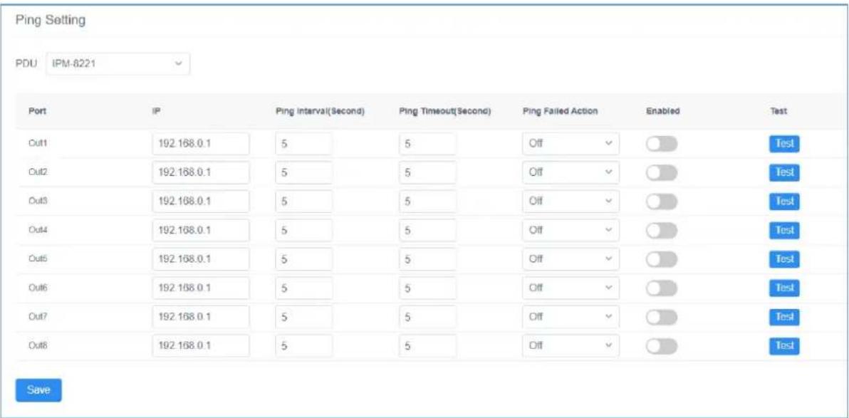
Figure 4-3-13 Ping Setting Page Screenshot
4.3.3 Global Setting
Sub-function options include: Mail Setting, System Time Setting, Clear Energy, Restore to Factory Setting, Upgrade, and Language Settings
Mail Settings
The email setting function allows you to send PDU alarms and logs to a specified email address after setting an email address. After setting the email address, you can send a test email to check whether the email address is correct. After the modification, click the Save button to save the settings.
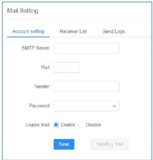
Figure 4-3-14 Mail Setting for Account Setting Page Screenshot
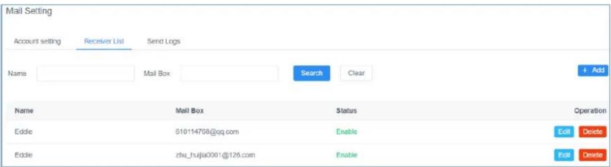
Figure 4-3-15 Mail Setting for Receiver List Page Screenshot
You can search, query, edit, and delete email addresses in the receiving email list, and enable or disable email sending Settings. It is convenient for you to adjust according to the actual application situation.
Mail logs record sent mail information. You can query, delete, or export mail logs based on the time setting.
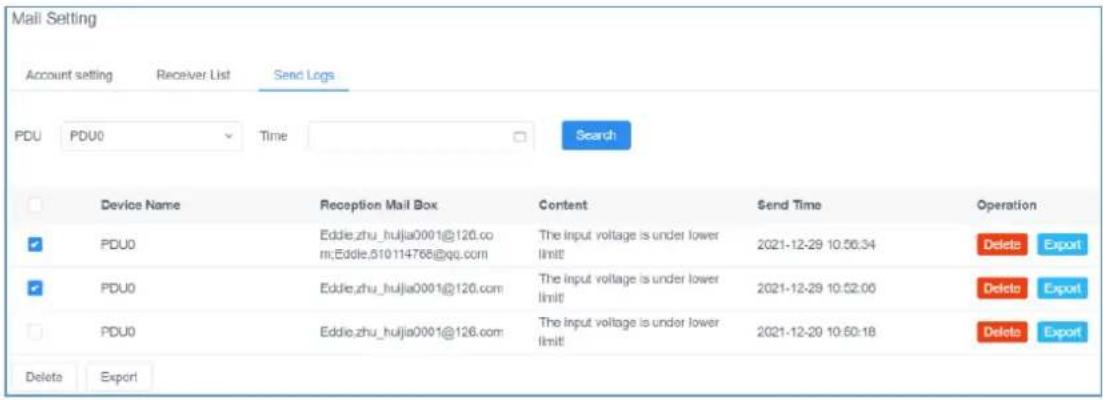
Figure 4-3-16 Mail Setting for Send Logs Page Screenshot
■ System Time Setting
You can set the system time of the PDU and synchronize the time with the browser you log in to. The PDU supports the NTP time server protocol and automatically updates the system time. Users can also change the access address of the time server. After the modification, click the Save button to save the settings.
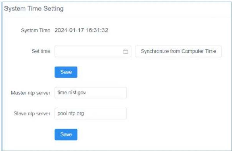
Figure 4-3-17 System Time Setting Page Screenshot
■ Clear Energy
The Clear Energy function can reset the accumulated electric quantity of the PDU. After setting, the PDU system will restart the calculation of accumulated electric quantity.
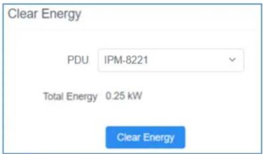
Figure 4-3-18 Clear Energy Page Screenshot
■ Restore to Factory Setting
The factory setting restoration function restores the PDU to its factory settings and deletes all records and information in the PDU. Exercise caution when performing this operation. After the default setting is restored, the system will restart. Then you can perform related operations, like setting PDUs again.
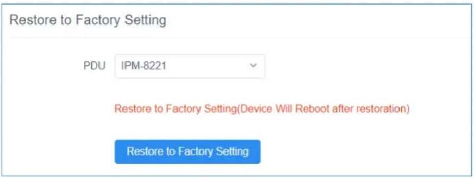
Figure 4-3-19 Restore to Factory Setting Page Screenshot
■ Upgrade
After system upgrade, you can query the latest version of the PDU software you use on our website, download the file and save it in the specified file directory on the PC, select the upgrade file to complete the software update of the PDU system, and restart the PDU system after the system is updated.
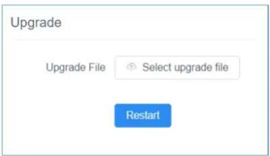
Figure 4-3-20 Upgrade Page Screenshot
■ Language Setting
The PDU currently supports two languages: Simplified Chinese and English. English is the default setting. Select the system language you want through the drop-down option, and click the Save button and the system will be changed to the language you selected.
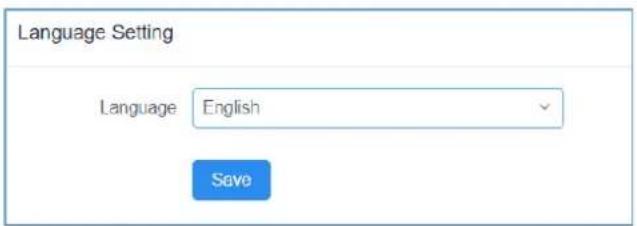
Figure 4-3-21 Language Setting Page Screenshot
4.3.4 Threshold Setting
Sub-function options include Input Warning Setting, Output Warning Setting, Output Off Setting, and Temp. & Humidity Warning Setting.
■ Input Warning Setting
You can set the maximum and minimum values of the input current and voltage. When the current or voltage exceeds the threshold, the PDU automatically sends alarm logs to the specified email box address, and an alarm message is displayed on the home page, facilitating query and handling after your next log-in. After the modification, click the Save button to save the settings.
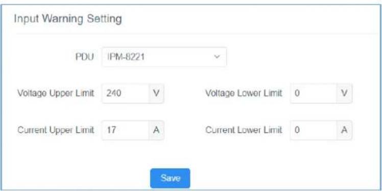
Figure 4-3-22 Input Warning Setting Page Screenshot
■ Output Warning Setting
You can set the upper limit and lower limit of the output current of each power output port respectively to ensure that the electrical device works within a safe current range. If the output current exceeds the set range, the system will issue an alarm. You can also set parameters in batches. Treat the same setup requirements uniformly. After the modification, click the Save button to save the settings.
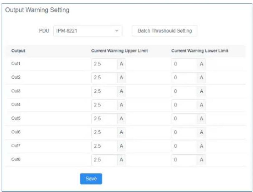
Figure 4-3-23 Output Warning Setting Page Screenshot
■ Output Off Setting
When the current exceeds the upper limit, the system automatically disconnects the corresponding port to eliminate the risk of device overload. You can also set the output power in batches. Treat the same setup requirements uniformly. After the modification, click the Save button to save the settings.
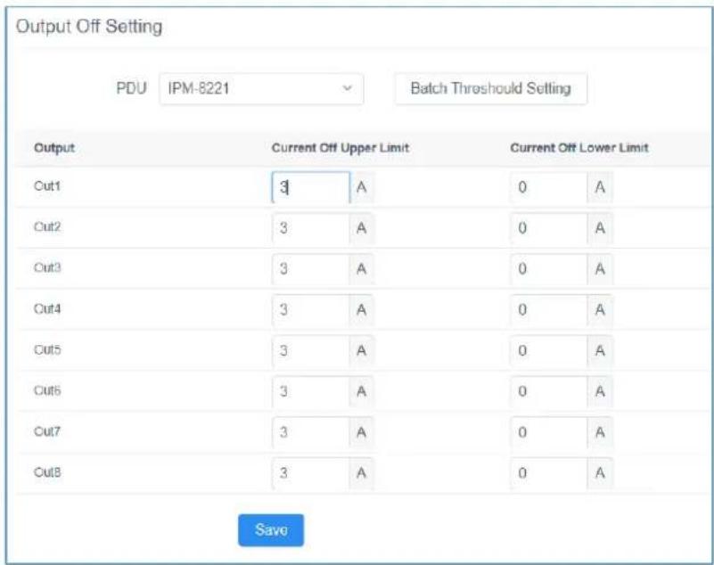
Figure 4-3-24 Output Off Setting Page Screenshot
■ Temp & Humidity Warning Setting
The IPM-8221 goes beyond power management by offering dedicated port for ambient Temperature and Humidity (T/H) sensor (sensor provided with product). When you insert the sensor to Sensor Port of the PDU. You can obtain the ambient temperature and humidity of the PDU surroundings on the homepage of the web interface. You also can set the upper and lower limits of temperature and humidity. When the upper and lower limits of temperature and humidity are exceeded, the system generates an environmental alarm. After the modification, click the Save button to save the settings.

Figure 4-3-25 Home Page for Temperature and Humidity Screenshot
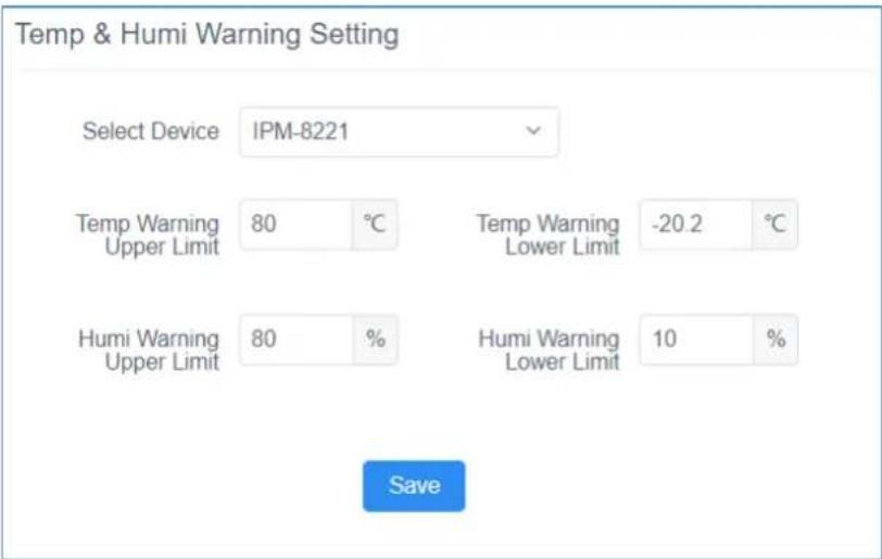
Figure 4-3-26 Temp & Humidity Warning Setting Page Screenshot
4.4 About
Click the About. The About screen in Figure 4-4-1 appears. You can obtain the network configuration information, name, hardware version information, and device serial number of the PDU.
About
All Rights Reserved: Copyright PLANET Technology Corporation
IP Addr: 192.168.0.10
Subnet Mask 255.255.255.0
Gateway: 192.168.0.1
Primary DNS Server: 8.8.8.8
Secondary DNS Server: 168.95.1.1
MAC Address: A8:F7:E0:C3:FF:A8
Device Name: IPM-8221
Device UID: G023000000010000
Hw Version v1.11
Sw Version v1.20240111
Product Serial: SN0001
Figure 4-4-1 About Page Screenshot
4.4.1 More Warnings
You can click the More Warnings button in the upper part of the main window into System Logs. System Logs are classified into two types: System Logs and User Operation Logs. The system logs list is displayed in the pop-up window. You can view the time, type, and description of system logs. You also can click the Voltage/Current/Environment Warnings button in the upper part of the main window into System Logs to review the specified type logs.
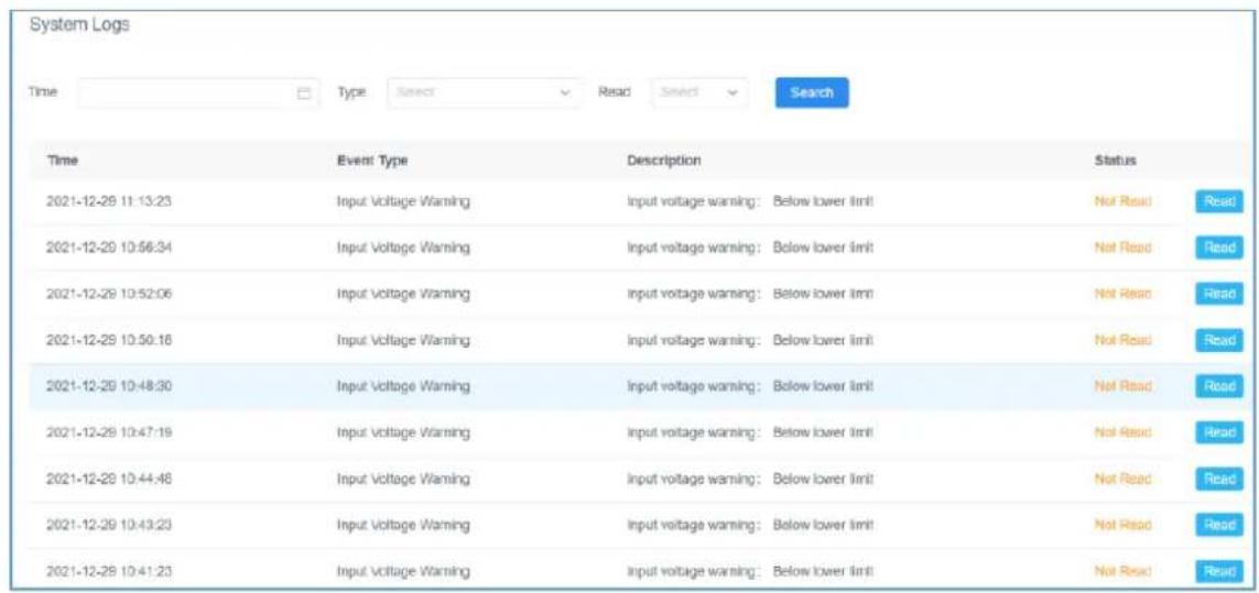
Figure 4-4-2 System Logs Page Screenshot
You can click the log-in user drop-down list in the upper right corner of the window and choose User Operation Logs to display the user Operation Logs window, which displays the log time, user, log description, and accessed IP address.
| User Operation Logs | |||
| Time | Search | ||
| Time | User | Description | IP |
| 2021-12-31 09:25:08 | A user is modified [.user1] | 192.168.0.153 | |
| 2021-12-31 08:42:48 | A user is added [.user1] | 192.168.0.153 | |
| 2021-12-30 16:09:44 | A user is modified [.admin] | 192.168.0.153 | |
| 2021-12-30 15:27:42 | On [.addr:0] | 192.168.0.153 | |
| 2021-12-30 15:27:42 | On [.addr:0] | 192.168.0.153 | |
| 2021-12-30 15:27:23 | On [.addr:0] | 192.168.0.153 | |
| 2021-12-29 11:14:12 | 修改了输入告警设置 [addr:0] | 192.168.0.150 | |
| 2021-12-29 11:13:14 | 修改了输入告警设置 [addr:0] | 192.168.0.150 | |
| 2021-12-29 10:57:46 | Input warning settings are modified [.addr:0] | 192.168.0.150 | |
Figure 4-4-3 User Operation Logs Page Screenshot
Appendix A: Safety Instructions
General
■ This product is for indoor use only.
- Read all of these instructions. Save them for future reference.
■ Follow all warnings and instructions marked on the device.
Do not place the device on any unstable surface (cart, stand, table, etc.). If the device falls, serious damage will result.
■ Do not use the device near water.
■ Do not place the device near, or over, radiators or heat registers.
The device cabinet is provided with slots and openings to allow for adequate ventilation. To ensure reliable operation, and to protect against overheating, these openings must never be blocked or covered.
The device should never be placed on a soft surface (bed, sofa, rug, etc.) as this will block its ventilation openings. Likewise, the device should not be placed in a built-in enclosure unless adequate ventilation has been provided.
■ Never spill liquid of any kind on the device.
- Unplug the device from the wall outlet before cleaning. Do not use liquid or aerosol cleaners. Use a damp cloth for cleaning. - The device should be operated from the type of power source indicated on the marking label. If you are not sure of the type of power available, consult your dealer or local power company. - This equipment is designed to be equipped with 100-230V alternating IT power distribution system.
■ To prevent damage to your installation it is important that all devices are properly grounded.
The device is equipped with a 3-wire grounding type plug. This is a safety feature. If you are unable to insert the plug into the outlet, contact your electrician to replace your obsolete outlet. Do not attempt to defeat the purpose of the grounding-type plug. Always follow your local/national wiring codes.
Do not allow anything to rest on the power cord or cables. Route the power cord and cables so that they cannot be stepped on or tripped over.
To help protect your system from sudden, transient increases and decreases in electrical power, use a surge suppressor, line conditioner, or uninterruptible power supply (UPS).
■ Position system cables and power cables carefully; Be sure that nothing rests on any cables.
■ When connecting or disconnecting power to hot pluggable power supplies, observe the following guidelines:
■ Install the power supply before connecting the power cable to the power supply.
■ Unplug the power cable before removing the power supply.
If the system has multiple sources of power, disconnect power from the system by unplugging all power cables from the power supplies.
■ Never push objects of any kind into or through cabinet slots. They may touch dangerous voltage points or short out parts resulting in a risk of fire or electrical shock.
■ Do not attempt to service the device yourself. Refer all servicing to qualified service personnel.
If the following conditions occur, unplug the device from the wall outlet and bring it to qualified service personnel for repair.
■ The power cord or plug has become damaged or frayed.
■ Liquid has been spilled into the device.
■ The device has been exposed to rain or water.
■ The device has been dropped, or the cabinet has been damaged.
■ The device exhibits a distinct change in performance, indicating a need for service.
■ The device does not operate normally when the operating instructions are followed.
■ Only adjust those controls that are covered in the operating instructions.
■ Improper adjustment of other controls may result in damage that will require extensive work by a qualified technician to repair.
Rack Mounting
■ When extending the device out of the rack, ensure that the rack is smooth and stable.
Do not overload the AC branches that supply power to the frame; The carrying capacity of the whole frame should not exceed eighty percent of the power of the branch.
■ Make sure that all equipment used on the rack – including power strips and other electrical connectors – is properly grounded.
■ Ensure that proper airflow is provided to devices in the rack.
■ Ensure that the operating ambient temperature of the rack environment does not exceed the maximum ambient temperature specified for the equipment by the manufacturer
■ Do not step on or stand on any device when servicing other devices in a rack.
The Eco PDU's Main Power Cord
■ Please use the power cord attached to this package. If it is necessary to replace the power cord attached to this package with another power cord,
■ Please confirm that the power cable must meet at least the cable standards attached to this package.
Appendix B: IP Address Determination
If you are an administrator and log in for the first time, you must connect the switcher to assign an IP address for user access. The PDU device provides the means that, in each case, your computer must be on the same network segment as the switch. When you are connected and logged in, you can assign a fixed network address to the device.
Specific methods are as follows:
- Set the IP address of your PC to 192.168.0.xxx. Here XXX represents any number other than 10. (192.168.0.10 is the default address of switch)
- In the network address column of your browser, enter the recognized IP address of the switch you want to connect to 192.168.0.10.
- When you are connected and logged in, assign a set of fixed IP addresses corresponding to its Network segment to the device (see Network Setting).
- After you log out, be sure to reset your computer IP address back to the original value.
- Once you are logged in, please go to the Network Settings page to set up a temporary IP environment.
- IP-based 8-port Switched Power Manager
- with 2 Cascaded Ports
- Copyright
- Federal Communication Commission Interference Statement
- FCC Caution
- Federal Communication Commission (FCC) Radiation Exposure Statement
- Safety
- CE Mark Warning
- WEEE Regulation
- Revision
- Table of Contents
- Chapter 1. Product Introduction ....5
- Chapter 2. Hardware Interface ......13
- Chapter 3. Web Login....19
- Chapter 4. Web-based Management....22
- Appendix A: Safety Instructions ....43
- Appendix B: IP Address Determination....45
- Chapter 1. Product Introduction
- Package Contents
- Overview
- Fulfilling Your Power Requirements with IP-enabled Power Outlets Embracing ESG Principles
- Intelligent Power Management
- Real-time Current Monitoring
- Scheduled Power On/Off
- Enhanced Overload Protection
- Enabling Environmental Monitoring with Precision
- Streamlined Connectivity with Cascade Ports
- Efficient Energy Management for Cost Savings
- Features
- Hardware
- Power Distribution
- Remote Access
- Management
- Security
- Specifications
- Chapter 2. Hardware Interface
- Physical Descriptions
- Front Panel
- Rear Panel
- Installation Precautions
- Hardware Installation
- Rack Mounting
- Initial Utility Installation
- PDU Discovery through PLANET NMS Controller
- (NMS-500/NMS-1000V)
- Chapter 3. Web Login
- Network Connection
- Starting Web Management
- Step 1: Log in the web setting page of PDU
- Step 3: Network Configuration
- Step 4. Change of administrator Log-in
- Chapter 4. Web-based Management
- Main Page / Home Page
- ■ Page Components
- Socket Access
- Statistics
- Threshold
- Control
- Settings
- User Management
- ■ User List
- ■ Add User
- ■ Permission Management
- ■ Blacklist Setting
- Device Deployment
- ■ Cascade Setting
- ■ Network Setting
- ■ Port Name Setting
- ■ Port Delay Setting
- ■ SNMP Setting
- ■ Ping Setting
- Global Setting
- Mail Settings
- ■ System Time Setting
- ■ Clear Energy
- ■ Restore to Factory Setting
- ■ Upgrade
- ■ Language Setting
- Threshold Setting
- ■ Input Warning Setting
- ■ Output Warning Setting
- ■ Output Off Setting
- ■ Temp & Humidity Warning Setting
- About
- More Warnings
- Appendix A: Safety Instructions
- General
- Rack Mounting
- The Eco PDU's Main Power Cord
- Appendix B: IP Address Determination
- Specific methods are as follows:
Brand : Planet
Model : IPM-8221
Category : Switch