
BS 312.2 - Loudspeaker ELAC - Free user manual and instructions
Find the device manual for free BS 312.2 ELAC in PDF.


| Product Type | Bookshelf Loudspeaker |
| Brand | ELAC |
| Model | BS 312.2 |
| Speaker Type | 2-way bass reflex |
| Tweeter | 1-inch soft dome |
| Woofer | 5.25-inch aluminum cone |
| Frequency Response | 42 Hz – 50 kHz |
| Impedance | 4 ohms |
| Sensitivity | 87 dB (2.83 V/1 m) |
| Recommended Amplifier Power | 30 – 120 watts per channel |
| Dimensions (H x W x D) | 330 x 205 x 264 mm (13.0 x 8.1 x 10.4 in) |
| Weight (each) | 7.5 kg (16.5 lbs) |
| Finish | Black or white high-gloss lacquer |
| Connection Type | Gold-plated binding posts (bi-wire capable) |
| Recommended Placement | On stands or bookshelf, at least 30 cm from rear wall |
| Cleaning Instructions | Wipe with a soft, dry cloth; do not use solvents |
| Safety Precautions | Keep away from moisture, heat sources, and magnetic fields |
| Accessories Included | Magnetic grille, foam port plugs |
| Warranty | 5 years (depending on region) |
Frequently Asked Questions - BS 312.2 ELAC
User questions about BS 312.2 ELAC
0 question about this device. Answer the ones you know or ask your own.
Ask a new question about this device
Download the instructions for your Loudspeaker in PDF format for free! Find your manual BS 312.2 - ELAC and take your electronic device back in hand. On this page are published all the documents necessary for the use of your device. BS 312.2 by ELAC.
USER MANUAL BS 312.2 ELAC
natural_image
Diagram of two cylindrical batteries with positive and negative terminals, enclosed in a circular housing (no text or symbols)natural_image
Diagram showing a 3D cube with a shaded rectangular area and two curved lines labeled 'C' extending from it, against a vertical wall (no text or symbols)natural_image
Pure electrical circuit lines without any symbols
natural_image
Simple line drawing of two parallel supports with mounting holes (no text or symbols)
natural_image
Pure mechanical linkage diagram without any text, numbers, or symbols
natural_image
Pure mechanical linkage diagram with three vertical components and connecting rods (no text or symbols)natural_image
Simple line drawing of a room with a wall-mounted object and a curved armchair, connected by a dashed line (no text or symbols)- Please read and follow these safety instructions.
- Keep them safe for future reference.
- Observe all warnings on the speaker and in the manual. Please check the speaker for damage before use. The speaker must be in perfect working condition. Damaged parts may lead to personal injury.
2. Use only as directed
- Connect the speaker(s) according to the instructions in the manual.
- Many ELAC speakers are equipped with spikes and/or anti-slip feet.
They are explicitly provided for levelling the speaker. For levelling on an uneven floor, unscrew the spikes or anti-slip feet by 2-3 turns of thread. The speaker should always be in perfect vertical alignment: the stability of the speaker must not be compromised by using spikes or anti-slip feet as the speaker may tip-over.
3. Location
- Install the speakers on a level surface only
-
When choosing the location of these speakers do not place them in locations that are:
-
In direct sunlight
- Very humid
- Prone to vibrations
- Exceptionally hot or cold
- Near CRT Televisions (the speakers are not magnetically shielded and may cause color issues with a CRT based TV)
- Close to magnetic cards (Since the speakers are not magnetically shielded placing magnetic cards such as credit cards or commuter cards may cause them to fail).
WARNING! Please ensure the product is perfectly stable to avoid injury from tip-over. Please note, that stability can be increased by using spikes on carpeted surfaces. However, the mounting of spikes must be carried out carefully due to their very sharp ends which may cause injuries. The stability on slippery floors can be increased by using Velcro fastening tape or double-sided adhesive tape. Do not install the speaker near any heat sources such as radiators, heating valves, stoves, or other apparatus (including amplifiers) that produce heat, or in areas where there is a risk of explosion.
- Do not block any ventilation openings. Install in accordance with the manufacturer's instructions.
- Do not install the speaker in a closed rack or in a closed cupboard.
- Do not put burning candles on or near the speaker.
- Do not install the speaker near transformers because electromagnetic stray fields can cause hum noise on woofers.
In combination with certain materials / lacquers / material surfaces, anti-slip feet or spike washers may cause colored imprints on the surfaces.
4. Overload
Extreme overload of the device due to very high volume may cause damage to individual components. Because of the possible danger, you should never leave loudspeakers under extreme overload conditions unattended.
5. Service
DANGER! Do not open the cabinet because the components and conductors may carry current! Servicing to be carried out by qualified service personnel only.
Servicing is required when the loudspeaker has been damaged in any way, such as damage to the power supply cord or the plug, or when liquid has been spilled or objects have fallen onto the loudspeaker, the speaker has been exposed to rain or moisture, does not operate normally, or has been dropped. To reduce the risk of electric shock, do not open the loudspeaker. Servicing should be carried out by qualified service personnel only.
6. Cleaning
NOTE: Clean only with soft, smooth cloth or with dust brush. Do not use scouring agents, alcohol, benzene, furniture polish or other agents for cleaning! Modern furniture is often coated with multiple varnishes and plastics which can be treated with chemical agents. Some of these agents contain substances which degrade or soften the rubber feet. Therefore we advise that you place an anti-slip mat underneath the loudspeaker(s).
7. Volume
CAUTION! Continuous high volume may cause severe damage to your hearing. Please listen responsibly.
8. Disposal
The packaging is made from recyclable materials. Dispose of this in an environmentally friendly manner. At end of life do not dispose of the speaker(s) with standard household waste. The speaker must be recycled in accordance with local legislation. Ask your local government for further information on recycling as the device contains valuable raw materials. Disable the speaker(s) before disposal.
PHILOSOPHY

Thank you for purchasing this ELAC product.
Since the time we started (1926), ELAC has always striven to achieve the very best.
Your new ELAC speakers are built to the highest standards using high-quality components that are carefully constructed to deliver the best-in-class sound quality. They are developed by a passionate group of individuals whose soul purpose is to bring a new dimension of sound quality into your home. Enjoy!

Avoid damage to the speakers and other components:
- Carefully unbox the speakers carefully to avoid physically damaging your speakers.
- Use appropriate gauge wires (minimum of 12 gauge wire for runs up to 25 feet).
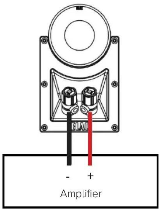
- Make sure wire polarity is connected correctly. Most speaker cables are coded for ease of use. Make sure positive (red) connection on the amplifier terminal is connected to the positive (red) on your speakers. Follow the same instructions for the negative side. Strip off approximately 1/2" of the insulation from the ends of the speaker cable, twist the bare strands and insert into the binding post.
- Ensure your equipment is turned off before connecting speakers.
- Check to ensure positive and negative wires are not touching each other once they're connected to the speaker terminals.
Installing and Removing the Magnetically Attached Grills
The grills of your ELAC speakers are designed to be removable if desired. To remove it, hold the top or bottom edges of the grill and pull gently. To replace the grill, place the grill in the normal position on the cabinet and the magnets will hold the grill in place.
IMPORTANT!
ELAC Floorstanding Speakers Safety Clip
Some ELAC Floorstanding speakers include a safety clip pre-installed on the back of the cabinet for securing to a wall to prevent tip-over. Use support hooks (not included) screwed into a wall and pass appropriate size cord (not included) around the hook and through the safety clip. Test to ensure mounted hooks and cord will prevent tipping of the speaker.
Support Hooks and Cords (not included)

Wal
CAUTION:
The safety clip is not a mounting fixture and the speaker should not be hung on the wall using the clip. ELAC does not claim responsibility for damage resulting from improper assembly, installation, insufficient strength of the installation materials, misuse or natural disasters.
OUTRIGGER PLATE & SPIKE INSTALLATION

Using the included outrigger plate provides a wider support base for the speaker cabinet. The included spikes improve stability on uneven surfaces and thickly carpeted floors.
Please use caution when dealing with the spikes as they are sharp.
IMPORTANT: When using these spikes on hard surfaces such as wood or tile floors be sure to use the provided floor discs to protect your floor from damage.
IMPORTANT: In order to prevent scratching or damage to the cabinet, turn the speaker upside down onto a soft surface while you attach the outrigger feet and spikes. We highly recommend a second person help with this process.
Attach the outrigger plates with the provided machine screws.
Screw in the spikes as shown in the picture to the right. The speaker can now be turn back over. Please be careful when handling the speaker with the spikes installed. If you have hard wood or tile floors please use the provided floor discs.
Using the supplied allen wrench ad-just the height of the spikes until the speaker sits level and all four spikes are touching the floor.
Once the speaker is level, use the supplied covers to lock the spikes into place.

natural_image
Pure electrical circuit lines without any symbols
natural_image
Simple line drawing of two parallel supports with mounting holes (no text or symbols)
natural_image
Pure mechanical linkage diagram without any text, numbers, or symbols
natural_image
Pure mechanical linkage diagram with three vertical components and connecting rods (no text or symbols)
input midrange/treble
jumper
input woofer
Some of our speakers allow separate operation of the treble/midrange and the woofer by means of two amplifiers (Bi Amping) or by means of separate connecting cables (Bi Wiring). For this purpose, the speakers are provided with double terminals. The two pairs of connecting jacks that are provided with jumpers were designed for standard operation (with one amplifier). For Bi Wiring/Bi Amping, the jumpers must be removed. The passive crossover networks of the individual drivers remain in operation. This way, the use of special filter crossover networks is not required.

One pair of connecting jacks is used for the connection to the network of the midrange/tweeter.
The other pair is used for the connection to the network of the woofer.
Due to separate wiring (Bi Wiring), a decoupling of the two legs is obtained.
This reduces cross-talking between the midrange/tweeter leg and the woofer leg.
There are different types of connecting cables that can be used. For example, low-inductance cables are suitable for the treble area and particularly large cables are suitable for the woofer area.
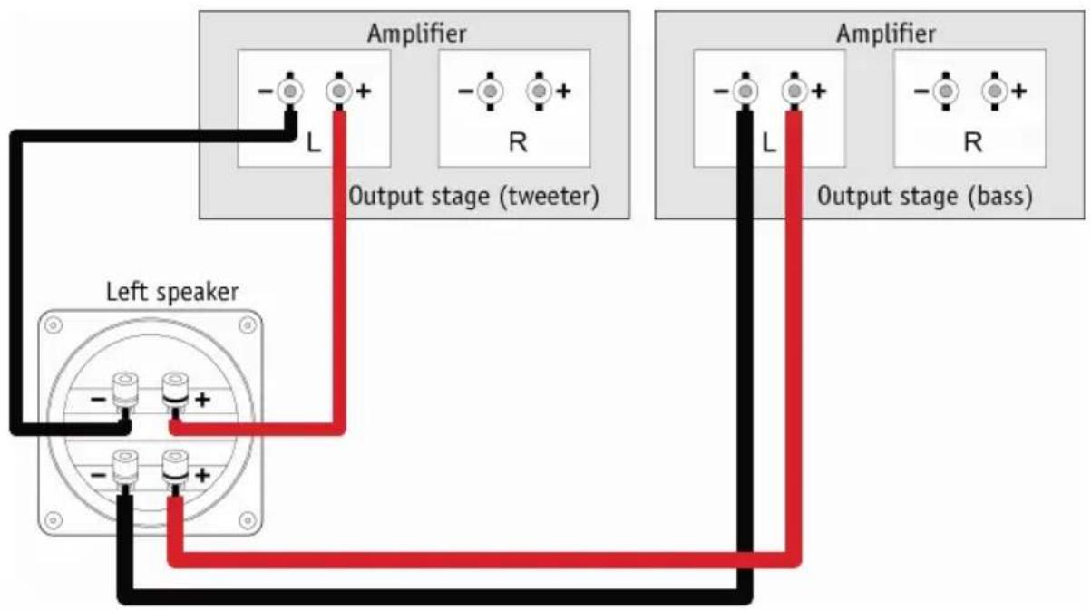
If both legs are operated through separate output stages, it is possible to choose amplifiers that allow the transmis-sion of high, midrange or low frequencies. With separate volume controls for both legs, it will be easier to provide a sound balance that offers perfect adaption to the living room environment (room acoustics).
Please note, that different models of output stages may not provide the same volume when fed by one source through a y adapter. The reason for this lies in different amplification factors that occur between the input and the output levels.
To ensure, that the sound balance will not be defined at random, the amplifiers provide level controls that enable perfect adjustment of the desired sound balance.
It would be advantageous to choose a high-quality amplifier for one of the two stereo output stages. Its volume control can be used to adjust the desired sound balance. The other output stage would be a puristic element that does not offer any adjustment options.
It is important to mention, that there must be prestages for adjusting the volume and programmes. If the prestige provides only one output, a standard cable for the Y adapter can be used.
SPEAKER PLACEMENT

Achieve maximum performance and optimal sound quality from your ELAC speakers with proper speaker placement and set-up. While not all rooms are the same, use the following guidelines to configure the speakers for your particular room. There are no “exact” rules or boundaries in setting up your speakers but the following suggestions will help optimize your desired results. Remember the best sound set-up is what sounds best for you so don’t be afraid to experiment and make adjustments to the placement and directivity of the speakers.
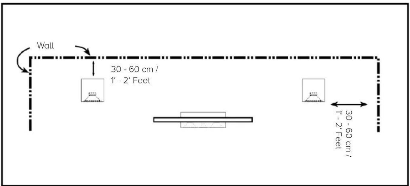
Place the speakers approximately one to two feet away from boundaries such as wall(s) and especially corners. Close proximity to a side or rear wall will enhance bass performance (output), but being too close (particularly to a corner) may result in bass that is unnatural. If a corner location is unavoidable, try to position the loudspeaker so that the distance to the rear wall is not equal to the distance to the side wall.
STEREO-SETUP

For the best results and the most realistic stereo image and lifelike sound, place the speakers so that an equilateral triangle is created between the speakers and your favorite listening position. This set up creates the optimum imaging performance.
If you find that your front left and right speakers are too far apart, angle (toe in) them towards the listening position to gain a more focused central image.

flowchart
graph TD
    A["Speaker (Left)"] --> B["TV & Center Speaker"]
    B --> C["Speaker (Right)"]
    D["Listening Position"] --> B
    style A fill:#f9f,stroke:#333
    style B fill:#ccf,stroke:#333
    style C fill:#cfc,stroke:#333
2-Canal-Stereo-Setup
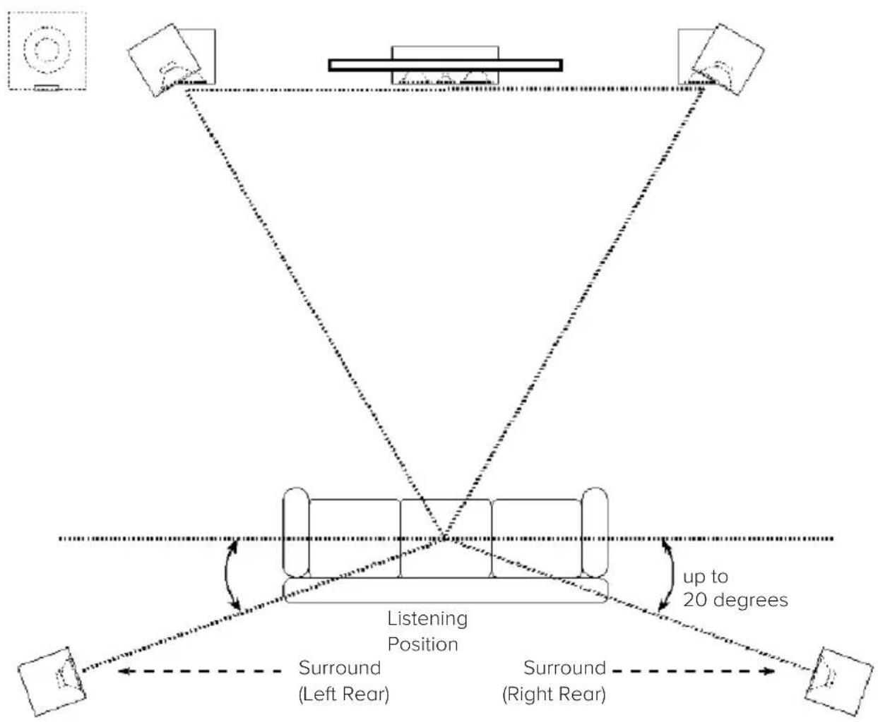
Whether you use the Adante bookshelf or the Adante floorstanding speakers for a 5.1-channel surround set-up, avoid placing the surround speakers forward of your listening position. The surround speakers should be spread apart wider than the front speakers. In addition, elevate the speakers to the same height or slightly higher as the front speakers for the most enveloping sound field. Like the front speakers, you may need to experiment with the positioning by pointing the rear surround speakers towards the listening area.
flowchart
graph TD
    A["Device 1"] --> B["Left Rear"]
    C["Device 2"] --> D["Right Rear"]
    E["Device 3"] --> F["Left Rear"]
    G["Device 4"] --> H["Right Rear"]
    I["Device 5"] --> J["Left Rear"]
    K["Device 6"] --> L["Right Rear"]
    M["Device 7"] --> N["Left Rear"]
    O["Device 8"] --> P["Right Rear"]
    Q["Device 9"] --> R["Left Rear"]
    S["Device 10"] --> T["Right Rear"]
    U["Device 11"] --> V["Left Rear"]
    W["Device 12"] --> X["Right Rear"]
    Y["Device 13"] --> Z["Left Rear"]
    AA["Device 14"] --> AB["Right Rear"]
    AC["Device 15"] --> AD["Left Rear"]
    AE["Device 16"] --> AF["Right Rear"]
    AG["Device 17"] --> AH["Left Rear"]
    AI["Device 18"] --> AJ["Right Rear"]
    AK["Device 19"] --> AL["Left Rear"]
    AM["Device 20"] --> AN["Right Rear"]
    AO["Device 21"] --> AP["Left Rear"]
    AQ["Device 22"] --> AR["Right Rear"]
    AS["Device 23"] --> AT["Left Rear"]
    AU["Device 24"] --> AV["Right Rear"]
    AW["Device 25"] --> AX["Left Rear"]
    AY["Device 26"] --> AZ["Right Rear"]
    BA["Device 27"] --> BB["Left Rear"]
    BC["Device 28"] --> BD["Right Rear"]
    BE["Device 29"] --> BF["Left Rear"]
    BG["Device 30"] --> BH["Right Rear"]
    BI["Device 31"] --> BJ["Left Rear"]
    BK["Device 32"] --> BL["Right Rear"]
    BM["Device 33"] --> BN["Left Rear"]
    BO["Device 34"] --> BP["Right Rear"]
    BZ["Device 35"] --> CA["Left Rear"]
    CB["Device 36"] --> CC["Right Rear"]
    CD["Device 37"] --> CE["Left Rear"]
    CF["Device 38"] --> CG["Right Rear"]
    DH["Device 39"] --> DI["Left Rear"]
    DJ["Device 40"] --> DE["Right Rear"]
    DF["Device 41"] --> DG["Left Rear"]
    DHX["Device 42"] --> DHX["Right Rear"]
5.1 Canal-Surround-Setup
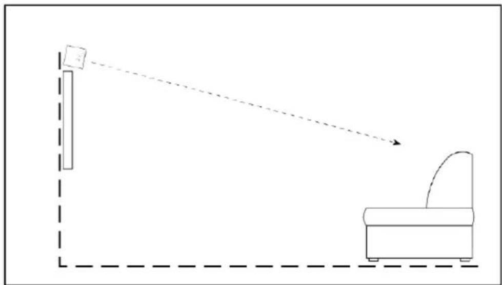
The ELAC center channel is designed to produce dialog sounds and should be positioned above or below your television. Align it with the center of the television. As much as possible, try to keep the speaker close to the same level (height) as your front speakers for a more even sound stage. Keeping the same height for the center channel can be very challenging so it might be necessary to tilt the center speaker up (if too low) or down (if too high), to aim it towards the listening area.

flowchart
graph TD
    A["Place above or bleow"] --> B["Television"]
    C["Sound waves"] --> B
    D["Sound waves"] --> B
    E["Sound waves"] --> B
natural_image
Simple line drawing of a room with a wall-mounted object and a curved arm, connected by a dashed line (no text or symbols)Optimal results for the center are obtained by setting the receiver/processor center channel size to small. If you have a choice, set the crossover frequency between 50 to 100Hz.
ELAC Americas Inc.
North America Limited Liability Warranty
Passive Speakers (No Built-in Amplifi er)

ELAC Americas Inc. warrants to the original purchaser that this product be free from defects and or workmanship for a period of 3 (Three) years from the original date of purchase. During this time period, repair or replacement of parts will be free of charge to the original owner (See below limitations). Shipping to and return from the repair center will be the responsibility of the original purchaser.
Limitations
Warranty begins on the date of original purchase from an authorized ELAC Americas Inc. dealer. Product is warranted only if used in home applications within the max power rating specified in this manual. Commercial use of this product is not warranted.
Product that has been modified or altered in anyway will not be warranted. Product that has been abused or subjected to faulty equipment will not be warranted. Products with defaced or removed serial numbers will not be warranted.
If service is required
In the event that service is required, please contact ELAC America at 714-252-8843 or at customerservice@elac.us to arrange for service or replacement. You will be responsible to provide proof of purchase (Copy or original sales receipt). Shipping to and from our repair center will be the responsibility of the original purchaser.
Warranty Outside of North America
This warranty applies to products purchased in the United States and Canada. For warranty claims outside of North America please contact the local dealer/distributor in the country of purchase.



natural_image
Audio waveform visualization with no text or symbolsELAC
The life of sound.
ELAC Americas llc.
11145 Knott ave. Suites e & f
Cypress, Ca. 90630
ELAC Electroacoustic GmbH
Fraunhoferstraße 16
D-24118 Kiel, Germany
- Use only as directed
- Location
- Overload
- Service
- Cleaning
- Volume
- Disposal
- PHILOSOPHY
- Installing and Removing the Magnetically Attached Grills
- IMPORTANT!
- ELAC Floorstanding Speakers Safety Clip
- CAUTION:
- OUTRIGGER PLATE & SPIKE INSTALLATION
- SPEAKER PLACEMENT
- STEREO-SETUP
- Limitations
- If service is required
- Warranty Outside of North America
- ELAC
Brand : ELAC
Model : BS 312.2
Category : Loudspeaker