
ANI-42HPIP - Router A-NeuVideo - Free user manual and instructions
Find the device manual for free ANI-42HPIP A-NeuVideo in PDF.


| Product Type | 4x2 HDMI Multiviewer / Router |
| HDMI Inputs | 4 x HDMI |
| HDMI Outputs | 2 x HDMI (mirrored) |
| Analog Audio Output | Balanced Stereo via 5-pin Terminal Block |
| Maximum Resolution | 4K@60Hz (4:4:4, 8-bit) |
| HDCP Compliance | HDCP 1.x and 2.2 |
| Video Bandwidth | 18 Gbps / 600 MHz |
| Multiview Modes | Quad (2x2), 3+1, Side-by-Side, PiP |
| Matrix Mode | Independent routing per output (resolutions < 4K) |
| Seamless Switching | Yes (when output resolution < 4K; black briefly at 4K) |
| Control Interfaces | Front Panel, WebGUI, RS-232, Telnet, IR Remote |
| Power Supply | DC 12V / 3A (included) |
| Power Consumption | 27.5 W |
| Dimensions (Case Only) | 17.2 x 1.7 x 10.6 in (438 x 44 x 268 mm) |
| Dimensions (All Inclusive) | 17.2 x 1.9 x 10.9 in (438 x 49 x 276 mm) |
| Weight | 7.5 lb (3,400 g) |
| Chassis Material | Aluminum (Black) |
| Operating Temperature | 32°F – 104°F (0°C – 40°C) |
| Storage Temperature | -4°F – 140°F (-20°C – 60°C) |
| Relative Humidity | 20% – 90% RH (non-condensing) |
| Warranty | 3 Years |
| ESD Protection | ±8 kV (Air), ±4 kV (Contact) |
Frequently Asked Questions - ANI-42HPIP A-NeuVideo
User questions about ANI-42HPIP A-NeuVideo
0 question about this device. Answer the ones you know or ask your own.
Ask a new question about this device
Download the instructions for your Router in PDF format for free! Find your manual ANI-42HPIP - A-NeuVideo and take your electronic device back in hand. On this page are published all the documents necessary for the use of your device. ANI-42HPIP by A-NeuVideo.
USER MANUAL ANI-42HPIP A-NeuVideo
Before attempting to use this unit, please check the packaging and make sure the following items are contained in the box:
• ANI-42HPIP 4x2 HDMI Multiviewer
• 12V/3A DC Power Adapter
• (2) 5-pin Terminal Block
- Remote Control (ANI-180)
- Rackmount Ears (Set of 2)

SAFETY INFORMATION

-
To ensure the best results from this product, please read this manual and all other documentation before operating your equipment. Retain all documentation for future reference.
-
Follow all instructions printed on unit chassis for proper operation.
-
To reduce the risk of fire, do not spill water or other liquids into or on the unit, or operate the unit while standing in liquid.
-
Make sure power outlets conform to the power requirements listed on the back of the unit. Keep unit protected from rain, water and excessive moisture.
-
Do not attempt to clean the unit with chemical solvents or aerosol cleaners, as this may damage the unit. Dust with a clean dry cloth.
-
Do not use the unit if the electrical power cord is frayed or broken. The power supply cords should be routed so that they are not likely to be walked on or pinched by items placed upon or against them, paying particular attention to cords and plugs, convenience receptacles, and the point where they exit from the appliance.
-
Do not force switched or external connections in any way. They should all connect easily, without needing to be forced.
-
Always operate the unit with the AC ground wire connected to the electrical system ground. Precautions should be taken so that the means of grounding of a piece of equipment is not defeated.
-
AC voltage must be correct and the same as that printed on the rear of the unit. Damage caused by connection to improper AC voltage is not covered by any warranty.
-
Turn power off and disconnect unit from AC current before making connections.
-
Never hold a power switch in the "ON" position.
-
This unit should be installed in a cool dry place, away from sources of excessive heat, vibration, dust, moisture and cold. Do not use the unit near stoves, heat registers, radiators, or other heat producing devices.
-
Do not block fan intake or exhaust ports. Do not operate equipment on a surface or in an environment which may impede the normal flow of air around the unit, such as a bed, rug, carpet, or completely enclosed rack. If the unit is used in an extremely dusty or smoky environment, the unit should be periodically "blown free" of foreign dust and matter.
-
To reduce the risk of electric shock, do not remove the cover. There are no user serviceable parts inside. Refer all servicing to qualified service personnel. There are no user serviceable parts inside.
-
When moving the unit, disconnect input ports first, then remove the power cable; finally, disconnect the interconnecting cables to other devices.
-
Do not drive the inputs with a signal level greater than that required to drive equipment to full output.
-
The equipment power cord should be unplugged from the outlet when left unused for a long period of time.
-
Save the carton and packing material even if the equipment has arrived in good condition. Should you ever need to ship the unit, use only the original factory packing.
-
Service Information Equipment should be serviced by qualified service personnel when:
A. The power supply cord or the plug has been damaged.
B. Objects have fallen, or liquid has been spilled into the equipment.
C. The equipment has been exposed to rain.
D. The equipment does not appear to operate normally, or exhibits a marked change in performance.
E. The equipment has been dropped, or the enclosure damaged.
CONTENTS
INTRODUCTION....1
FEATURES / APPLICATIONS / SYSTEM REQUIREMENTS ...2
SPECIFICATIONS 3
OPERATION CONTROLS & FUNCTIONS......4
FRONT PANEL 4
REAR PANEL 5
REMOTE CONTROL 6
RS-232 CONTROL/TELNETCONTROL 7
RS-232/TELNETCOMMANDS....8
WEBGUI CONTROL....13
CONNECTION DIAGRAM 20
VIDEO SPECIFICATIONS 21
DEAR CUSTOMER
Thank you for purchasing this product. For optimum performance and safety, please read these instructions carefully before connecting, operating or adjusting this product. Please keep this manual for future reference.
INTRODUCTION
The ANI-42HPIP 4x2 Multiviewer is a high performance HDMI switch with integrated scaling and multi-windowing technology. It is an ideal solution for monitoring or displaying multiple sources simultaneously for use in control rooms, conference rooms or classrooms. Video resolutions up to 4K@60Hz and LPCM audio up to 7.1 channels at 192kHz are supported on both input and output and this unit is fully compatible with the HDCP 1.x and 2.2 standards.
Any of (4) different HDMI sources may be displayed individually, full screen, or they can be displayed using a variety of multi-window modes including quad view and PiP with the output being sent to (2) mirrored HDMI outputs (4K@50/60Hz output supports quad view and full screen only). Management of input/window routing, position and sizing can be controlled easily by use of the front panel controls as well as by WebGUI, RS-232, Telnet and IR remote control options. This product has a 3 year warranty.
SAFETY PRECAUTIONS
Please read all instructions before attempting to unpack, install or operate this equipment and before connecting the power supply. Please keep the following in mind as you unpack and install this equipment:
- Always follow basic safety precautions to reduce the risk of fire, electrical shock and injury to persons.
- To prevent fire or shock hazard, do not expose the unit to rain, moisture or install this product near water.
- Never spill liquid of any kind on or into this product.
- Never push an object of any kind into this product through any openings or empty slots in the unit, as you may damage parts inside the unit.
- Do not attach the power supply cabling to building surfaces.
- Use only the supplied power supply unit (PSU). Do not use the PSU if it is damaged.
- Do not allow anything to rest on the power cabling or allow any weight to be placed upon it or any person walk on it.
- To protect the unit from overheating, do not block any vents or openings in the unit housing that provide ventilation and allow for sufficient space for air to circulate around the unit.
DISCLAIMERS
The information in this manual has been carefully checked and is believed to be accurate. We assume no responsibility for any infringements of patents or other rights of third parties which may result from its use.
We assume no responsibility for any inaccuracies that may be contained in this document. We make no commitment to update or to keep current the information contained in this document.
We reserve the right to make improvements to this document and/or product at any time and without notice.
COPYRIGHT NOTICE
No part of this document may be reproduced, transmitted, transcribed, stored in a retrieval system, or any of its part translated into any language or computer file, in any form or by any means — electronic, mechanical, magnetic, optical, chemical, manual, or otherwise — without the express written permission and consent.
© Copyright 2021. All Rights Reserved.
Version 1.7 FEB 2021
TRADEMARK ACKNOWLEDGMENTS
All products or service names mentioned in this document may be trademarks of the companies with which they are associated.
FEATURES
• HDMI inputs and outputs with 18Gbps (600MHz) 4K UHD support
• DVI 1.0 compatible with the use of an HDMI-DVI adaptor
• HDCP 1.x and 2.2 compliant
• Supports HD resolutions up to 4K@60Hz (4:4:4, 8-bit)
• (4) HDMI inputs and (2) mirrored HDMI outputs
- Seamless switching (no loss of sync to display) when output resolution is less than 4K (not supported in multi-window mode). For seamless switching when output resolution is 4K, see ANI-42HPIPX.
- Supports PiP (Picture-in-Picture), side by side, 3+1 quad view, and 2x2 quad view display options with independent audio source selection
NOTE: 4K@50/60Hz output supports 2x2 Quad View only and is limited to 1080p/4K sources. See "Features Support Chart" on Pg. 2 for supported Input/Output resolutions.
- Supports the ability to store a multi-window arrangement as a preset that can be recalled later
• Each window can have a border with a selectable color
- Uploadable and freely positioned graphic logo support
NOTE: See "Features Support Chart" on Pg. 2 for supported Input/Output resolutions.
- Supports easy adjustment of window size, position and settings in the PiP windowing mode via the WebGUI
- Matrix mode supports input and output resolutions up to 1080p@60Hz with a single shared audio source (Outputs are mirrored at higher resolutions)
- Controllable via front panel buttons, WebGUI, Telnet, RS-232 and IR remote
APPLICATIONS
- Entertainment Room & Home Theater
• Show Room & Demo Room - Lecture Room & Hall Presentation
• Public Commercial Display
SYSTEM REQUIREMENTS
- HDMI source equipment such as media players, video game consoles or set-top boxes.
- HDMI receiving equipment such as HDTVs, monitors or audio amplifiers.
FEATURE SUPPORT CHART
| Mode/Feature | INPUT/OUTPUT TIMING COMBINATIONS | |||
| ≤1080p to ≤1080p Any 4K to ≤1080p Any to 4K@24/30Hz Any to 4K@50/60Hz | ||||
| Matrix Mode Supported Unsupported Unsupported Unsupported | ||||
| Switch Mode (Mirrored) N/A Supported Supported Supported | ||||
| Quad View Supported Supported Supported Supported | ||||
| 3+1 Quad View Supported Supported Supported | ||||
| Side by Side View | Supported Supported Supported Unsupported | |||
| PiP View | Supported Supported Supported Unsupported | |||
| Window Borders | Supported Supported Supported Unsupported | |||
| Logo Display | Supported Supported Supported Unsupported | |||
SPECIFICATIONS
• HDMI Bandwidth: 600MHz/18Gbps
- Input Ports: (4) HDMI
- Output Ports:
• (2) HDMI
• Balanced Stereo (5-pin Terminal Block)
• Control Interfaces:
• RS-232 (5-pin Terminal Block)
• IP Control (RJ-45)
• Power Supply: 12V/3A DC (US/EU standards, CE/FCC/UL certified)
• ESD Protection: Human Body Model:
-
±8kV (Air Discharge)
• ±4kV (Contact Discharge) -
Dimensions (WxHxD): 17.2 x 1.7 x 10.6 in (438x44x268mm) [Case Only] / 17.2 x 1.9 x 10.9 in (438x49x276mm) [All Inclusive]
• Weight: 7.5 lb / 3,400g
• Chassis Material: Aluminum - Silkscreen Color: Black
- Operating Temperature: 0°C - 40°C / 32°F - 104°F
• Storage Temperature: -20°C - 60°C/-4°F - 140°F
• Relative Humidity: 20 - 90% RH (Non-condensing)
• Power Consumption: 27.5W
As product improvements are continuous, specifications are subject to change without notice.
FRONT PANEL

① POWER: Press this button to power the unit on (green LED) or place it into stand-by mode (red LED).
② IR WINDOW: Accepts IR signals from the included IR remote for control of this unit only.
3 MATRIX A/B IN1\~IN4: These input selection buttons behave differently depending on the current input and output resolutions in use.
A. ALL INPUTS AND OUTPUTS ARE BELOW 4K: Press any of these buttons to seamlessly switch to the selected input (IN1\~IN4) for display on the associated output (A or B).
B. ANY INPUT OR OUTPUT IS 4K: Press any of these buttons to seamlessly switch to the selected input (IN1\~IN4) for display on both outputs simultaneously.
NOTE: Audio for both outputs will follow the most recently selected input (from A or B) in both modes.
4 MULTIVIEW: Press any of these buttons to switch immediately to the corresponding Multiview output mode.
5 WINDOW SOURCE SELECT: Press these buttons to sequentially switch through the available inputs for each window in Multiview output modes.
6 MENU: Press to enter the LCD menu, or to back out from menu items.
⑦ ENTER: Press to confirm a selection within the LCD menu or to go deeper into a menu item.
8 + & -: Press to move up and down or adjust selections within menus.
9 LOCK: Press to lock all button functions on the front panel. Press the button again to release the lock function. The LCD will display a "Lock" message when the function is active.
10 PRESET: Press this button to switch between the "Preset Load" and "Preset Save" modes. Pressing the button a 3rd time exits the Preset menu.
A. PRESET SAVE: When in "Preset Save" mode, pressing the "Enter" button will save the currently displayed window layout.
B. PRESET LOAD: When in the "Preset Load" mode, pressing the "Enter" button will load the previously saved window layout.
NOTE: The audio selection is not saved as a part of the preset, only the window layout.
⑪ LCD WINDOW: Displays the unit's menu, settings and information.
BACK PANEL

① HDMI IN 1\~4: Connect to HDMI source equipment such as media players, game consoles or set-top boxes. DVI source equipment may be connected by using an HDMI to DVI adapter.
② HDMI OUT A\~B: Connect to HDMI TVs, monitors or amplifiers for digital video and audio output. DVI display equipment may be connected by using HDMI to DVI adapter.
③ L/R OUT: Connect to powered speakers or an amplifier using a 5-pin adapter cable for balanced stereo analog audio output.
NOTE: Only LPCM 2.0 sources are supported. Bitstream audio sources will be muted automatically.
4 COM: Connect directly to a PC, laptop or other serial control device with a 3-pin adapter cable to send RS-232 commands to control the unit.
BALANCED
UNBALANCED
5 CONTROL: Connect directly, or through a network switch, to your PC/laptop to control the unit via Telnet/WebGUI.
6 SERVICE: This slot is reserved for firmware update use only.
⑦ DC 12V: Plug the 12V DC power adapter into the unit and connect it to an AC wall outlet for power.
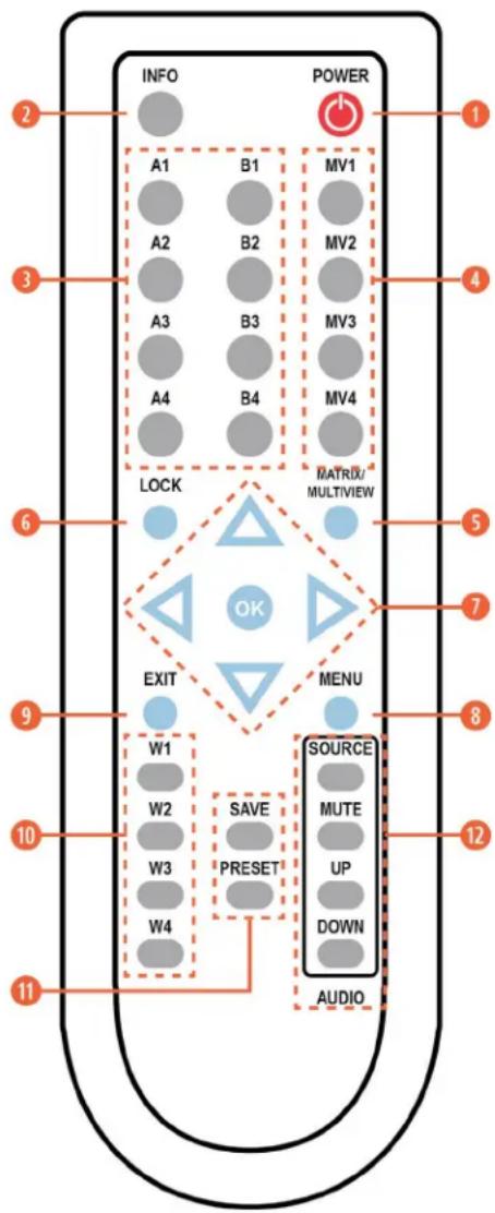
REMOTE CONTROL
① POWER: Power on the machine or enter to standby mode.
② INFO: Display the current status/ information of the unit.
③ A1\~A4 & B1\~B4: (Matrix Selection)
A. WHEN ALL INPUTS AND OUTPUTS ARE BELOW 4K: Press any of these buttons to seamlessly switch to the selected input (1\~4) for display on the associated output (A or B).
B. WHEN ANY INPUT OR OUTPUT IS 4K: Press any of these buttons to seamlessly switch to the selected input (1\~4) for display on both outputs simultaneously.
NOTE: Audio for both outputs will follow the most recently selected input (from A or B) in both modes.
4 MV1\~MV4: (Multiview Selection) Press these buttons to switch immediately to the corresponding Multiview output mode.
MV1: Switch to 2x2 quad view mode.
MV2: Switch to the 3+1 quad view mode.
MV3: Switch to the side-by-side view mode
MV4: Switch to PiP view mode.
5 MATRIX/MULTIVIEW: Press to toggle between the Matrix and Multiview modes.
6 LOCK: Press to lock all button functions on the front panel. Press the button again to release the lock function.
7 ARROWS (▲/▼/◄/►) & OK: Press the arrow buttons to navigate the LCD menu. Press the "OK" button to confirm a selection or to go deeper into a menu item.
⑧ MENU: Press to enter the LCD menu.
⑨ EXIT: Press to exit out of the current LCD menu item.
10 W1\~W4: (Window Source Selection) Press these buttons to sequentially switch through the available inputs for each window (1\~4) in Multiview output modes.
11 SAVE: Pressing this button will save the currently displayed window layout.
PRESET: Pressing this button will load the previously saved window layout.
12 SOURCE: Press this button to sequentially switch through the available audio sources.
MUTE: Press to toggle between muting and unmuting the audio output.
UP: Press this button to increase the audio output volume.
DOWN: Press this button to decrease the audio output volume.
NOTE: The volume controls only affect the analog audio output.
IR CODES
Custom Code: 8037 EXIT: 8037 D8
POWER: 8037 82 MATRIX_AIN1: 8037 88 MATRIX_BIN4: 8037 95 CH3_SEL: 8037 C5
ENTER: 8037 9D MATRIX_AIN2: 8037 8C MULTI_1: 8037 8A CH4_SEL: 8037 D9
MENU: 8037 84 MATRIX_AIN3: 8037 90 MULTI_2: 8037 8E INFO: 8037 86
DOWN: 8037 9E MATRIX_AIN4: 8037 85 MULTI_3: 8037 92 LOCK: 8037 C2
IRBTN_UP: 8037 9A MATRIX_BIN1: 8037 89 MULTI_4: 8037 C6 MA_MX: 8037 99
IRBTN_LEFT: 8037 9C
MATRIX_BIN2: 8037 8D
CH1_SEL: 8037 87
PRESET: 8037 CD
IRBTN_RIGHT: 8037 98
MATRIX_BIN3: 8037 91
CH2_SEL: 8037 C4
SAVE: 8037 CC
RS-232 CONTROL
| MATRIX TERMINAL | |
| PIN PINOUT | PIN PINOUT |
| 1 GND 1 | |
| 2 TX 2 RxD | |
| 3 RX 3 TxD | |
| 4 RTS 4 | |
| 5 | CTS 5 GND |
| 6 | |
| 7 | |
| 8 | |
| 9 | |
SERIAL PORT SETTINGS:
Baud Rate: 19200 bps
Data Bit: 8bits
Parity: None
Flow Control: None
Stop Bit: 1
TELNET CONTROL
Before attempting to use Telnet control, please ensure that both the unit and the PC are connected to the same active networks.
| TO ACCESS THE COMMAND LINE INTERFACE (CLI) | |
| Windows 7 | Click START, type “cmd” in the search field and press ENTER. |
| Windows XP | Click START > RUN, type “cmd”, and press ENTER. |
| Mac OS X | Click Go > Applications > Utilities > Terminal. |
Once in the Command Line Interface (CLI) type "TELNET" followed by the IP address of the unit (and the port number if it is non-standard) and then hit "ENTER". This will connect us to the unit we wish to control. Type "HELP" to list the available commands. See below for reference.
Microsoft Windows [Version 6.1.7601]
Copyright (c) 2009 Microsoft Corporation. All rights reserved.
C:\Users\Administrator>telnet 192.168.1.50 23
NOTE: If the IP address is changed then the IP address required for Telnet access will also change accordingly.
RS-232 & TELNET COMMANDS
| BASIC COMMANDS | ||
| COMMAND DESCRIPTION VARIABLES | ||
| HELP ← | Show the full command list. | |
| ? ← | Show the full command list. | |
| GET FW VER ← | Show the current firmware version. | |
| GET MODEL NAME ← | Show the model name. | |
| GET MODEL TYPE ← | Show the model type. | |
| SET FACTORY DEFAULT ← | Reset the unit to its factory defaults. | |
| SET POWER N1 ← | Turn the unit on or off (standby). Available values for | N1:ON [Power on]STANDBY [Standby mode] |
| GET POWER ← | Show the current power state. | |
| SET SYSTEM REBOOT ← | Reboot the unit. | |
| SET KEYLOCK N1 ← | Enable or disable the front panel key lock. | N1 = ON, OFF [Front panel lock state] |
| GET KEYLOCK ← | Show the current front panel lock state. | |
| ETHERNET CONFIGURATION | ||
| COMMAND DESCRIPTION VARIABLES | ||
| GET MAC 1 ADDR ← | Show the unit's MAC address. | |
| SET IP MODE N1 ← | Set the IP mode of the unit. Available values for N1: | STATIC [Static IP mode]DHCP [DHCP mode] |
| GET IP MODE ← | Show the current IP mode. | |
| GET IPCONFIG ← | Show the current IP configuration. | |
| SET IPADDR N1 ← | Set the unit's static IP address. N1 = X.X.X.X [X = 0~255, IP address] | |
| GET IPADDR ← | Show the current IP address. | |
| SET NETMASK N1 ← | Set the unit's netmask address. N1 = X.X.X.X [X = 0~255, Netmask] | |
| GET NETMASK ← | Show the current netmask. | |
| SET GATEWAY N1 ← | Set the unit's gateway address. | N1 = X.X.X.X [X = 0~255, Gateway] |
| GET GATEWAY ← | Show the current gateway address. | |
| VIDEO COMMANDS | ||
| COMMAND DESCRIPTION VARIABLES | ||
| SET IN N1 NAME N2 ← | Set the name for input N1. | N1 = 1~4 [Input number]N2 = {name} [24 characters max] |
| GET IN N1 NAME ← | Show the name of input N1. | N1 = 1~4 [Input number] |
| SET OUT N1 NAME N2 ← | Set the name for output N1. | N1 = A~B [Output letter]N2 = {name} [24 characters max] |
| GET OUT N1 NAME ← | Show the name of output N1. | N1 = A~B [Output letter] |
| VIDEO COMMANDS CONT'D | ||
| COMMAND DESCRIPTION VARIABLES | ||
| SET OUT N1 ROUTE N2 ← | Set the routing source for output N1 and switch to matrix mode. | N1 = A~B [Output letter]N2 = 1~4 [Input number] |
| GET OUT N1 ROUTE ← | Show the matrix mode routing source for output N1. | N1 = A~B [Output letter] |
| SET PRESET 1 SAVE ← | Save the current video layout as a preset. | |
| SET PRESET 1 LOAD ← | Load the saved video layout preset. | |
| SCALER COMMANDS | |||
| COMMAND DESCRIPTION VARIABLES | |||
| SET DISPLAY MODE N1← | Set the unit's output mode. Available values for N1:0 [Matrix mode]1 [Multiviewer mode] | ||
| GET DISPLAY MODE← | Show the unit's current output mode. | ||
| SET OUT A TIMING N1← | Set the output resolution and timing to use for both outputs. | Available values for N1:0 [Native (Output A)]1~36 [Output resolution] | |
| TIMING CODES:0 = Native1 = 640x4802 = 480p@603 = 576p@504 = 800x6005 = 848x4806 = 1024x7687 = 720p@508 = 720p@609 = 1280x76810 = 1280x80011 = 1280x96012 = 1280x102413 = 1360x76814 = 1366x76815 = 1400x105016 = 1440x90017 = 1600x900 (RB) | 18 = 1600x120019 = 1680x105020 = 1080i@5021 = 1080i@6022 = 1080p@2423 = 1080p@2524 = 1080p@3025 = 1080p@5026 = 1080p@6027 = 1920x1200 (RB)28 = 2048x1152 (RB)29 = 3840x2160p@2430 = 3840x2160p@2531 = 3840x2160p@3032 = 4096x2160p@2433 = 4096x2160p@2534 = 4096x2160p@3035 = 3840x2160p@5036 = 3840x2160p@60 | ||
| GET OUT A TIMING← | Show the current output resolution timing. | ||
| SET WINDOW LAYOUT MODE N1← | Set the multiview window layout mode and switch to multiview mode. | Available values for N1:1 [2x2 quad view]2 [3+1 quad view]3 [Side-by-Side]4 [Picture-in-Picture] | |
| GET WINDOW LAYOUT MODE← | Show the current window layout mode. | ||
| SCALER COMMANDS CONT'D | ||
| COMMAND DESCRIPTION VARIABLES | ||
| SET WINDOW N1 LAYOUT MODE N2 ASPECT RATIO N3← | Set the aspect ratio to use for window N1 in layout mode N2. | N1 = 1~4 [Window number]Available values for N2:2 [3+1 quad view]3 [Side-by-Side]Available values for N3:0 [Full window]1 [16:9 aspect]2 [4:3 aspect] |
| GET WINDOW N1 LAYOUT MODE N2 ASPECT RATIO← | Show the aspect ratio currently used by window N1 in layout mode N2. | N1 = 1~4 [Window number]Available values for N2:2 [3+1 quad view]3 [Side-by-Side] |
| SET WINDOW N1 ROUTEN2← | Set the input routing for the windows in multiview mode. | N1 = 1~4 [Window number]N2 = 1~4 [Input number] |
| GET WINDOW N1 ROUTE← | Show the input currently routed to window N1. | N1 = 1~4 [Window number] |
| SET WINDOW N1 BORDER N2← | Set the border color for window N1. N1 = 1~4 [Window number] | N1 = 1~4 [Window number]Available values for N2:0 [Off]1 [Blue]2 [Green]3 [Red]4 [Yellow]5 [Cyan]6 [Magenta] |
| GET WINDOW N1 BORDER← | Show the border color for window N1. N1 = 1~4 [Window number] | |
| SET PIP HSIZE N1← | Set the horizontal size of the PiP window (in pixels). N1 = 0~? [PiP width] | |
| NOTE: The maximum value depends on, and cannot exceed, the current output resolution's width. | ||
| GET PIP HSIZE← | Show the current horizontal PiP window size. | |
| SET PIP VSIZE N1← | Set the vertical size of the PiP window (in pixels). N1 = 0~? [PiP height] | |
| NOTE: The maximum value depends on, and cannot exceed, the current output resolution's height. | ||
| GET PIP VSIZE← | Show the current vertical PiP window size. | |
| SET PIP HPOSITION N1← | Set the horizontal position of the top left corner of the PiP window (in pixels). | N1 = 0~? [Horizontal position] |
| NOTE: The maximum value depends on, and cannot exceed, the current output resolution's width minus 1. | ||
| GET PIP HPOSITION← | Show the current horizontal position of the PiP window. | |
| SET PIP VPOSITION N1← | Set the vertical position of the top left corner of the PiP window (in pixels). | N1 = 0~? [Vertical position] |
| NOTE: The maximum value depends on, and cannot exceed, the current output resolution's height minus 1. | ||
| GET PIP VPOSITION← | Show the current vertical position of the PiP window. | |
| SET OUT A OSD BANNER DISPLAY N1← | Enable or disable the OSD info banner. N1 = ON, OFF [Info banner state] | |
| NOTE: Enabling the info banner will automatically disable display of the graphic logo. | ||
| OSD COMMANDS | ||
| COMMAND DESCRIPTION VARIABLES | ||
| GET OUT A OSD BANNER DISPLAY ← | Show the current state of the OSD info banner display. | |
| SET OUT A OSD BANNER LOCATION N1 ← | Set the position of the OSD info banner. Available values for N1:0 [Upper-left]1 [Middle-left]2 [Lower-left]3 [Upper-right]4 [Middle-right]5 [Lower-right] | |
| GET OUT A OSD BANNER LOCATION ← | Show the current position of the OSD info banner. | |
| SET OUT A INFO LOGO DISPLAY N1 ← | Enable or disable the graphic logo. N1 = ON, OFF [Graphic logo state] | |
| NOTE: Enabling the graphic logo will automatically disable display of the info banner. | ||
| GET OUT A INFO LOGO DISPLAY ← | Show the current status of the graphic logo display. | |
| SET OUT A INFO LOGO HPOSITION N1 ← | Set the horizontal position of the top left corner of the graphic logo (in pixels). | N1 = 0~? [Horizontal position] |
| NOTE: The maximum value depends on, and cannot exceed, the current output resolution's width minus 1. | ||
| GET OUT A INFO LOGO HPOSITION ← | Show the graphic logo's current horizontal position. | |
| SET OUT A INFO LOGO VPOSITION N1 ← | Set the vertical position of the top left corner of the graphic logo (in pixels). | N1 = 0~? [Vertical position] |
| NOTE: The maximum value depends on, and cannot exceed, the current output resolution's height minus 1. | ||
| GET OUT A INFO LOGO VPOSITION ← | Show the graphic logo's current vertical position. | |
| AUDIO COMMANDS | ||
| COMMAND DESCRIPTION VARIABLES | ||
| SET AUDIO OUT A MUTE N1 ← | Enable or disable muting the audio output. Available values for N1:OFF [Un-muted]ON [Muted] | |
| GET AUDIO OUT A MUTE ← | Show the current audio mute state. | |
| SET AUDIO OUT A ROUTE N1 ← | Set Input N1 as the audio source to output. N1 = 1~4 | [Input number] |
| GET AUDIO OUT A ROUTE ← | Show the current audio source. | |
| SET AUDIO OUT A VOLUME N1 ← | Set or adjust the analog audio output volume. Available values for N1:0~100 [Set volume in dB units]UP [Raise volume by 1]DOWN [Lower volume by 1] | |
| GET AUDIO OUT A VOLUME ← | Show the current analog audio volume value. | |
| SET AUDIO OUT A DELAY N1 ← | Set the analog audio delay value (in milliseconds). | N1 = 13~100 [Audio delay in ms] |
| NOTE: The range provided is for 48KHz sources. Increasing the sample rate will reduce the maximum delay range. | ||
| GET AUDIO OUT A DELAY ← | Show the current analog audio delay value. | |
| EDID MANAGEMENT | |||
| COMMAND DESCRIPTION VARIABLES | |||
| SET IN N1 EDID N2 ← | Set the EDID to use on Input N1. | N1 = 1~4 [Input number] | |
| Available values for N2:1 [FHD/2CH]2 [FHD/MCH]3 [UHD/2CH]4 [UHD/MCH] | 5 [UHD+/2CH]6 [UHD+/MCH]7~10 [User EDID 1~4]11 [Sink A]12 [Sink B] | ||
| GET IN N1 EDID ← | Show the EDID used by Input N1 N1 = 1~4 [Input number] | ||
| SET EDID N1 NAME N2 ← | Set the name for User EDID N1. N1 = 7~10 [User EDID 1~4]N2 = {name} [20 characters max] | ||
| GET EDID N1 NAME ← | Show the name of EDID N1. (User EDIDs only) N1 = 7~10 [User EDID 1~4] | ||
| SET ALL IN EDID MODE N1 ← | Set the EDID mode to “All EDID” or “Appoint”. | Available values for N1:ON [All EDID mode]OFF [Appoint mode] | |
| GET ALL IN EDID MODE ← | Show the current “All EDID” mode state. | ||
| SET ALL IN EDID N1 ← | Set the EDID to use when “All EDID” mode is active. | Available values for N1:1 [FHD/2CH]2 [FHD/MCH]3 [UHD/2CH]4 [UHD/MCH] | 5 [UHD+/2CH]6 [UHD+/MCH]7~10 [User EDID 1~4]11 [Sink A]12 [Sink B] |
| GET ALL IN EDID ← | Show the current EDID used by “All EDID” mode. | ||
| SET IN N1 MATRIX HDCP MODE N2 ← | Set the HDCP mode to use with Input N1 in matrix mode. | N1 = 1~4 [Input number]Available values for N2:0 [Disable HDCP]1 [Refer to source]2 [Refer to display] | |
| GET IN N1 MATRIX HDCP MODE ← | Show the HDCP mode currently used with Input N1 in matrix mode. | N1 = 1~4 [Input number] | |
| SET IN N1 MULTIVIEW HDCP MODE N2 ← | Set the HDCP version to enforce on Input N1 in multiviewer mode. | N1 = 1~4 [Input number]Available values for N2:0 [Disable HDCP]1 [HDCP 1.4]2 [HDCP 2.2] | |
| GET IN N1 MULTIVIEW HDCP MODE ← | Show the HDCP mode currently used with Input N1 in multiviewer mode. | N1 = 1~4 [Input number] | |
| SET WINDOW OUT N1 HDCP MUTE N2 ← | Set the behavior of Output N1 if the HDCP version of a source is not supported. | N1 = A~B [Output letter]Available values for N2:0 [Blank Window]1 [Disable Output] | |
| GET WINDOW OUT N1 HDCP MUTE ← | Show the behavior of Output N1 if the HDCP version of a source is not supported. | N1 = A~B [Output letter] | |
NOTE: Commands will not be executed unless followed by a carriage return. Commands are not case-sensitive.
WEBGUI CONTROL
DEVICE DISCOVERY:
Please obtain the “Device Discovery” software from our website A-Neuvideo.com and save it in a directory where you can easily find it. Connect the unit and your PC/Laptop to the same active network and execute the “Device Discovery”
software. Click on "Find Devices on Network" and a list of devices connected to the local network will show up indicating their current IP address.
NOTE: The unit's default IP address is 192.168.1.50.
By clicking on one of the listed devices you will be presented with the network details of that particular device.
- IP Mode: If you choose, you can alter the static IP network settings for the device, or switch the unit into DHCP mode to automatically obtain proper network settings from a local DHCP server. To switch to DHCP mode, please select DHCP from the IP mode drop-down, then click "Save" followed by "Reboot".
- WebGUI Hotkey: Once you are satisfied with the network settings, you may use them to connect via Telnet or WebGUI. The network information window provides a convenient link to launch the WebGUI directly.
WEBGUI OVERVIEW:
By default, both the Username and Password are “admin” for the WebGUI. The administrator password can be changed within the “System Settings” tab of the WebGUI if desired. The following function tabs will always display on left side of the WebGUI to aid with navigation.
NOTE: The unit's default IP address is 192.168.1.50.
Input
Output
Windowing
Audio
Edid Settings
User Config
System Settings
Admin - Logout
All primary functions of this unit are controllable via the built in WebGUI, including Input, Output, Windowing, Audio, EDID Settings, User Config, and System settings. The individual functions will be introduced in the following sections.
WEBGUI CONTROL
INPUT:
This tab displays the current status of each of the (4) inputs, allows renaming each input, and provides a way to set the unit's HDCP handling behavior.
- Video Timing: Shows the currently detected resolution and timing of each video input.
- Color Mode: Shows the currently detected color space format of each video input.
-
Input 1\~4 Name: Allows each input to be renamed. To change an input's name, type the new name into the provided space and click on "Save".
-
HDCP: Allows setting the HDCP compliance behavior of each input individually. Due to the differences in the way the Matrix and Multiviewer modes function, each mode handles HDCP slightly differently.
| MATRIX MODE OPTIONS | |
| Refer to Source The input supports | up to the HDCP version required by the connected source. |
| Refer to Display The input supports | up to the HDCP version supported by the connected display. |
| HDCP Support Off HDCP support | is completely disabled. |
| MULTIVIEWER MODE OPTIONS | |
| HDCP 1.4 HDCP v1.4 (and below) | is supported by the input. |
| HDCP 2.2 HDCP v2.2 (and below) | is supported by the input. |
| HDCP Off HDCP support is completely disabled. | |
OUTPUT:
This tab displays the current status of both HDMI outputs as well as providing control over the output resolution, output names and HDCP failure handling. Additional output related functions also have controls on this tab, such as window borders, the OSD information display, and graphic logo uploading and placement.
- Output A/B: These (2) sections show the current output resolution as well as the detected details of the connected displays. Each output can also be renamed. To change an output's name, type the new name into the provided space and click on "Save".
There is also a dropdown to select how each output behaves if one of the windows displayed on it requires a version of HDCP the display can't support. To have the display show black in case of an HDCP failure, select "Blank Window".
To disable the output completely select "Disable Output".
- Output Resolution: The output resolution for both outputs can be freely selected by clicking on the provided dropdown. To have the output resolution automatically determined by the EDID of the display connected to Output A, select "NATIVE".
NOTE: Both outputs will always use the same resolution, regardless of windowing mode. See “Features Support Chart” on Pg. 2 for supported Input/Output resolutions.
- Window Border: This section provides controls to add a colored border to each window. Click the dropdown next to the window you wish to affect and select a border color, or "OFF". Selecting "OFF" will disable the border completely.
NOTE: See "Features Support Chart" on Pg. 2 for supported Input/Output resolutions.
WEBGUI CONTROL
- OSD Information: This section provides control over the OSD Information display for each window. When the OSD switch is set to "ON", each window will display (2) lines of input information including the input's name and detected resolution.
The position of the OSD Information is controlled by changing the "OSD Location" setting which provides (6) possible location presets: Up Left, Middle Left, Down Left, Up Right, Middle Right, Down Right.
NOTE: The OSD Information display is automatically disabled if the Logo function is enabled.
- Logo Information: This section provides a way to upload a graphic logo to the unit and display it on both outputs at a specified position. When the Logo switch is set to "ON" the currently loaded logo will display on both outputs. If no logo has been uploaded yet, a "No Image" error will be displayed.
To position the logo, type the X and Y coordinates into the spaces provided and click on the "Save" button. The X and Y coordinates correspond to the position of the upper left corner of the logo and cannot exceed the horizontal (X) or vertical (Y) size of the currently selected output resolution.
To upload a graphic logo, please click the "Choose File" button to open the file selection window and then select the graphic logo file (8-bit *.bmp format, 1920x1080 max resolution) located on your local PC. After selecting the file, click the "Load..." button to upload the logo to the unit.
NOTE: See "Features Support Chart" on Pg. 2 for supported Input/Output resolutions. The Logo display is automatically disabled if the OSD Information function is enabled.
WINDOWING:
This tab provides access to controls for selecting between the Matrix and Multiview output modes of the unit as well as controls over the distinct features supported by each mode. To switch between the Matrix and Multiview modes, simply click on the radio button next to the mode you wish to activate.
NOTE: See "Features Support Chart" on Pg. 2 for supported Input/Output resolutions.
- Matrix Mode: This mode provides a way to switch between the (4) available inputs with full screen output. To select a new input, click on the dropdown next to either Output A or Output B and select the new Input to route to that output. The switch will occur immediately.
NOTE: Selecting a new input overrides the audio source selection from the Audio tab and audio output will be from the most recently selected input.
The behavior of this mode is different depending on the resolution of the inputs and the selected output resolution.
A. All Inputs and Outputs are below 4K: Switching is seamless and each output can display an independently selected source.
B. Any Input or Output is 4K: Switching is seamless (sync to the display is continuous), but black will be briefly shown between switches.
- Multiview Mode: Multiview Mode provides a selection of (4) different multi-window display options: Quad View, 3+1 View, Side by Side, and Picture in Picture. In Multiview Mode, both outputs are always mirrored and display the same image.
NOTE: See "Features Support Chart" on Pg. 2 for supported Input/Output resolutions.
WEBGUI CONTROL
- Quad View: Quad View displays (4) equally sized windows. Each window has an independently selected source. Audio always follows the source selected in the Audio tab.
NOTE: See "Features Support Chart" on Pg. 2 for supported Input/Output resolutions.
- Window Source: To change the source for a specific window, click on the dropdown next to the window to change (1\~4) and select the preferred Input. The switch will occur immediately.
- 3+1 View: The 3+1 View displays (1) large window to the right and (3) equally sized, but smaller, windows on the left. Each window has an independently selected source and the aspect ratio of the video in each window can be changed. Audio always follows the source selected in the Audio tab.
NOTE: See "Features Support Chart" on Pg. 2 for supported Input/Output resolutions.
- Window Source: To change the source for a specific window, click on the dropdown next to the window to change (1\~4) and select the preferred Input. To change the aspect ratio of the source, as displayed within the window, click on the second dropdown and select "Full", "16:9", or "4:3". The switch or format change will occur immediately.
- Side By Side: The Side by Side mode displays (2) equally sized windows next to each other. Each window has an independently selected source and the aspect ratio of the video in each window can be changed. Audio always follows the source selected in the Audio tab.
NOTE: See "Features Support Chart" on Pg. 2 for supported Input/Output resolutions.
- Window Source: To change the source for a specific window, click on the dropdown next to the window to change (1\~2) and select the preferred Input. To change the aspect ratio of the source, as displayed within the window, click on the second dropdown and select "Full", "16:9", or "4:3". The switch or format change will occur immediately.
- PiP (Picture in Picture): The PiP mode displays (1) full screen window in the background with a 2nd, freely sizable and positioned window on top of it. Each window has an independently selected source. Audio always follows the source selected in the Audio tab.
NOTE: See "Features Support Chart" on Pg. 2 for supported Input/Output resolutions.
- Window Source: To change the source for a specific window, click on the dropdown next to the window to change (1\~2) and select the preferred Input. The switch will occur immediately.
- PiP Size: There are (2) ways to change the size of the PiP window. Clicking on the bottom right corner of the PiP window and dragging it will resize the window freely. For more precise adjustments, move the width and height sliders. The height and width values cannot exceed the horizontal or vertical size of the currently selected output resolution. Changes will occur immediately.
WEBGUI CONTROL
- PiP Position: There are (2) ways to change the position of the PiP window. Clicking on the PiP window and dragging it will move the window freely. To position the PiP window with more accuracy, move the X Position and Y Position sliders. The X and Y coordinates correspond to the position of the upper left corner of the PiP window and cannot exceed the horizontal (X) or vertical (Y) size of the currently selected output resolution. Changes will occur immediately.
AUDIO:
This tab provides control over the audio routed to both outputs as well as control over audio muting for both digital and analog outputs. Audio volume and delay control is also provided for the analog audio output.
- Window Audio Routing: A single selectable audio source is sent to all available outputs (HDMI and analog) in both Matrix and Multiviewer modes. Click on the dropdown to select the input to route audio from.
NOTE: In Matrix mode, changing a video source (for either output) will automatically change the audio routing selection to use that audio source for all outputs.
- Audio Mute: The audio output can be freely muted or unmuted. To mute all audio output, click the button so that it reads "Enable". To unmute all audio output, click the button so that it reads "Disable".
- Audio Volume: The analog audio volume can be adjusted from 0 to 100 by moving the slider left or right. Clicking on the plus or minus buttons will change the volume level (1) unit at a time. The current audio volume is listed above the volume slider.
NOTE: Only applicable with LPCM audio sources. Digital audio output is unaffected by this control.
- Audio Delay: The audio delay for the analog output can be adjusted by moving the slider left or right. Clicking on the plus or minus buttons will change the delay amount 1ms at a time. The current delay and detected sampling rate is listed above slider. The available delay range depends on the sample rate of the source as follows:
| AUDIO DELAY RANGES | |
| 44.1kHz/48kHz The delay range is | from 13 ~ 100ms |
| 88.2kHz/96kHz The delay range is | from 7 ~ 50ms |
| 176.4kHz/196kHz The delay range | is from 4 ~ 25ms |
NOTE: Only applicable with LPCM audio sources. Digital audio output is unaffected by this control.
EDID SETTINGS:
This unit provides the option of six standard EDIDs, two sink sourced EDIDs and four user uploaded EDIDs that can be assigned to each input port individually. The names of the four user uploaded EDIDs can changed if desired.
- Customer EDID Settings: To upload a User EDID, please click the "Upload" button next to the Customer EDID Settings item you would like to change. An EDID Upload window will appear, allowing you to locate and upload the preferred EDID file (*.bin format) from a local PC. Once the correct file has been selected, please click the "Upload" button in the window, and the file will be transferred to the unit.
To save an existing User EDID to your local PC please press the "Download" button next to the EDID you would like to
save. Depending on your browser settings you will either be asked where to save the downloaded file, or the file will be transferred to the default download location on your PC. To change the name of a Customer EDID, type the new name in the space provided, then click on the "Save Name" button.
WEBGUI CONTROL
- Sink EDID Download: To save the EDID from one of the connected displays to your local PC, select the appropriate sink from the dropdown list then press the "Download" button. Depending on your browser settings you will either be asked where to save the downloaded file, or the file will be transferred to the default download location on your PC.
- EDID Mode: The EDID Mode section provides controls for how to assign EDID to the unit's inputs. Selecting "Appoint" allows for different EDID to be assigned to each individual input, selecting "ALL" allows for a single EDID to be assigned to all inputs.
- Set EDID Input Content: Click on the preferred input(s) to open the EDID Source management window. Multiple inputs can be selected at once, if desired. Select the new EDID source to use and the change will occur immediately.
NOTE: In most cases, assigning a new EDID to an input will cause the affected input to briefly blink out while the source adapts to the new information.
- Unit's Default EDIDs: This unit provides the following (6) default EDIDs:
| UNIT'S DEFAULT EDIDS | ||
| FHD/2CH 1920x1080p@60Hz (148MHz) & 8-bit color LPCM 2.0 | ||
| FHD/MCH 1920x1080p@60Hz (148MHz) & 8-bit color LPCM 7.1 & Bitstream | ||
| UHD/2CH 3840x2160p@30Hz (297MHz) & Deep Color (8/10/12-bit) LPCM 2.0 | ||
| UHD/MCH 3840x2160p@30Hz (297MHz) & Deep Color (8/10/12-bit) LPCM 7.1 & Bitstream | ||
| UHD+/2CH 3840x2160p@60Hz (594MHz) & Deep Color (8/10/12-bit) LPCM 2.0 | ||
| UHD+/MCH 3840x2160p@60Hz (594MHz) & Deep Color (8/10/12-bit) LPCM 7.1 & Bitstream | ||
NOTE: In some rare cases it is possible for custom or external EDIDs to cause compatibility issues with certain sources. If this happens, it is recommended to switch to one of the (6) default EDIDs for maximum compatibility.
USER CONFIGURATION:
This tab provides User Configuration options including changing the password for the Administrator account, and both the user name and password for the General User account.
NOTE: The General User account has limited access to the WebGUI and only has access to the Input, Output, Windowing, and Audio tabs.
SYSTEM SETTINGS:
This tab provides system information, power control, Ethernet configuration options, system configuration backup/restore/reset, and firmware update functions.
- Power: Press this switch to toggle the unit's power between ON and OFF (standby mode).
NOTE: While in standby mode the unit's WebGUI, Telnet and RS-232 controls are still active. - Lock: Press this switch to enable or disable the front panel button lock function. When enabled, pressing the physical buttons on the front of the unit will have no effect.
- Network: IP mode may be switched between Static IP or DHCP. In Static IP mode the IP, netmask and gateway addresses may be manually set.
WEBGUI CONTROL
When in DHCP mode, the unit will attempt to connect to a local DHCP server and obtain IP, netmask and gateway addresses automatically. Please press "Save" after making any changes to the IP configuration or mode.
NOTE: The unit's default IP address is 192.168.1.50. If the IP address is changed then the IP address required for WebGUI/Telnet access will also change accordingly.
- Download Current Configuration: The current system configuration, including routing and presets, may be saved as an JSON file to a PC. Click the "Download" button to save the current system configuration to your local PC.
- Restore Configuration: Previously saved system configurations may be restored from a saved JSON file. Click the "Choose File" button to locate the saved JSON file, then click the "Restore" button.
- Reset to Default: Press the "ALL Reset" button to reset the unit to its factory default state. After the reset is complete, the unit will reboot automatically.
- Firmware Upgrade: To update the unit's firmware, click the "Choose File" button to open the file selection window and then select the firmware update file (*.bin format) located on your local PC. After selecting the file, click the "Upgrade" button to begin the firmware update process.
ADMIN - LOGOUT:
Admin - Logout
Clicking the red "Logout" tab will automatically log the currently connected user out of the WebGUI and return to login page.
CONNECTION DIAGRAM
![graph TD A["Blu-ray Player"] --> B["Set-top Box"] B --> C["Game Console Satellite Receiver"] C --> D["HVDC"] D --> E["AV Receiver"] F["HDMI Inputs"] --> G["HVDC"] G --> H["HVDC"] I["Balance Stereo Output"] --> J["Power Supply"] K["Serial Equipped Computer"] --> L["RS-232"] M["HDMI Outputs"] --> N["U…](/content/2026/05/899548/images/f7e1a2b3a261514f4087bba122840568a4f2c1dacf9ad03e73580c9c3a99ea37.jpg)
Multiview Screens:
| 1 | 2 | 2 | 1 | 1 | 2 | 2 |
| 3 | 4 | 3 | ||||
| 4 |
RESOLUTION SUPPORT TABLES
| PC RESOLUTIONS INPUT (HZ) OUTPUT (HZ) | |
| 640x480 60, 72, 75, 85 60 | |
| 800x600 56, 60, 72, 75, 85 60 | |
| 1024x768 60, 70, 75, 85 60 | |
| 1028x768 60, 75 60 | |
| 1280x800 60 (RB), 60 60 | |
| 1280x960 60 60 | |
| 1280x1024 60 60 | |
| 1360x768 60 60 | |
| 1366x768 60 60 | |
| 1400x1050 60 (RB), 60 60 | |
| 1440x900 60 (RB), 60 60 | |
| 1600x900 60 | |
| 1600x1200 60 60 | |
| 1680x1050 60 (RB), 60 60 | |
| 1920x1200 60 (RB), 60 60 (RB) | |
| 1920x1440 60 |
| TV RESOLUTIONS INPUT (HZ) OUTPUT (HZ) | ||
| 720x480i 59.94, 60 | ||
| 720x480p 59.94, 60 60 | ||
| 720x576i 50 | ||
| 720x576p 50 50 | ||
| 1280x720p 50, 59.94, 60 50, 60 | ||
| 1920x1080i | 50, 59.94, 60 50, 60 | |
| 1920x1080p | 23.97, 24, 25, 29.97, 30 | 24, 25, 30 |
| 50, 59.94, 60 50, 60 | ||
| 3840x2160p (YUV 4:2:0) | 50, 59.94, 60 | |
| 3840x2160p | 24, 25, 30 | 24, 25, 30 |
| 50, 59.94, 60 50, 60 | ||
| 4096x2160p | 24, 25, 30 | 24, 25, 30 |
| 50, 59.94, 60 60 | ||
PLEASE READ THE FOLLOWING TERMS AND CONDITIONS CAREFULLY BEFORE USING THIS HARDWARE, COMPONENTS AND SOFTWARE PROVIDED BY, THROUGH OR UNDER A-NeuVideo, INC (COLLECTIVELY, THE "PRODUCT"). By using installing or using the Product, you unconditionally signify your agreement to these Terms and Conditions. If you do not agree to these Terms and Conditions, do not use the Product and return the Product to A-NeuVideo, Inc. at the return address set forth on the Product's packing label at your expense. A-NeuVideo, Inc. may modify these Terms and Conditions at anytime, without notice to you.
RESTRICTIONS ON USE OF THE PRODUCT
It is your responsibility to read and understand the installation and operation instructions, both verbal and in writing, provided to you with respect to the Product. You are authorized to use the Product solely in connection with such instructions. Any use of the Product not in accordance with such instructions shall void any warranty pertaining to the Product. Any and all damages that may occur in the use of the Product that is not strictly in accordance with such instructions shall be borne by you and you agree to indemnify and hold harmless A-NeuVideo, Inc. from and against any such damage.
The Product is protected by certain intellectual property rights owned by or licensed to A-NeuVideo. Any intellectual property rights pertaining to the Product are licensed to you by A-NeuVideo, Inc. and/or its affiliates, including any manufacturers or distributors of the Product (collectively, "A-NeuVideo") for your personal use only, provided that you do not change or delete any proprietary notices that may be provided with respect to the Product.
The Product is sold to you and any use of any associated intellectual property is deemed to be licensed to you by A-NeuVideo for your personal use only. A-NeuVideo does not transfer either the title or the intellectual property rights to the Product and A-NeuVideo retains full and complete title to the intellectual property rights therein. All trademarks and logos are owned by A-NeuVideo or its licensors and providers of the Product, and you may not copy or use them in any manner without the prior written consent of A-NeuVideo, which consent may be withheld at the sole discretion of A-NeuVideo.
The functionality and usability of the Product is controlled by A-NeuVideo, Inc. from its offices within the State of Texas, United States of America. A-NeuVideo makes no representation that materials pertaining to the Product are appropriate or available for use in other locations other than the shipping address you provided with respect thereto. You are advised that the Product may be subject to U.S. export controls.
DISCLAIMERS AND LIMITATION OF LIABILITY
A-NeuVideo may change or modify the Product at any time, from time to time.
THE PRODUCT IS PROVIDED "AS IS" AND WITHOUT WARRANTIES OF ANY KIND EITHER EXPRESS OR IMPLIED. A-NEUVIDEO DOES NOT WARRANT OR MAKE ANY REPRESENTATIONS REGARDING THE USE OR THE RESULTS OF THE USE OF THE PRODUCT'S CORRECTNESS, ACCURACY, RELIABILITY, OR OTHERWISE.
A-NeuVideo has no duty or policy to update any information or statements pertaining to the Product and, therefore, such information or statements should not be relied upon as being current as of the date you use the Product. Moreover, any portion of the materials pertaining to the Product may include technical inaccuracies or typographical errors. Changes may be made from time to time without notice with respect to the Product.
TO THE FULLEST EXTENT PERMISSIBLE PURSUANT TO APPLICABLE LAW, A-NEUVIDEO DISCLAIMS ALL WARRANTIES, EXPRESS OR IMPLIED, INCLUDING, BUT NOT LIMITED TO IMPLIED WARRANTIES OF MERCHANTABILITY, FITNESS FOR A PARTICULAR PURPOSE AND NON-INFRINGEMENT. A-NEUVIDEO DOES NOT WARRANT THE ACCURACY, COMPLETENESS OR USEFULNESS OF ANY INFORMATION WITH RESPECT TO THE PRODUCT. A-NEUVIDEO DOES NOT WARRANT THAT THE FUNCTIONS PERTAINING TO THE PRODUCT WILL BE ERROR-FREE, THAT DEFECTS WITH RESPECT TO THE PRODUCT WILL BE CORRECTED, OR THAT THE MATERIALS PERTAINING THERETO ARE FREE OF DEFECTS OR OTHER HARMFUL COMPONENTS. A-NEUVIDEO WILL USE ITS REASONABLE EFFORTS TO CORRECT ANY DEFECTS IN THE PRODUCT UPON TIMELY WRITTEN NOTICE FROM YOU NOT TO EXCEED 10 BUSINESS DAYS AFTER RECEIPT BY YOU OF THE PRODUCT, BUT YOU (AND NOT A-NEUVIDEO) ASSUME THE ENTIRE COST OF ALL NECESSARY SERVICING, REPAIR AND CORRECTION THAT WAS CAUSED BY YOU UNLESS OTHERWISE AGREED TO IN A SEPARATE WRITING BY A-NEUVIDEO.
UNDER NO CIRCUMSTANCES, INCLUDING, BUT NOT LIMITED TO, NEGLIGENCE, SHALL A-NEUVIDEO BE LIABLE FOR ANY SPECIAL OR CONSEQUENTIAL DAMAGES THAT RESULT FROM THE USE OF, OR THE INABILITY TO USE THE PRODUCT IN ACCORDANCE WITH ITS SPECIFICATIONS, EVEN IF A-NEUVIDEO OR ITS REPRESENTATIVES HAVE BEEN ADVISED OF THE POSSIBILITY OF SUCH DAMAGES. IN NO EVENT SHALL A-NEUVIDEO'S TOTAL LIABILITY TO YOU FROM ALL DAMAGES, LOSSES, AND CAUSES OF ACTION (WHETHER IN CONTRACT, OR OTHERWISE) EXCEED THE AMOUNT YOU PAID TO A-NEUVIDEO, IF ANY, FOR THE PRODUCT.
- SAFETY INFORMATION
- CONTENTS
- DEAR CUSTOMER
- INTRODUCTION
- SAFETY PRECAUTIONS
- DISCLAIMERS
- COPYRIGHT NOTICE
- TRADEMARK ACKNOWLEDGMENTS
- FEATURES
- APPLICATIONS
- SYSTEM REQUIREMENTS
- SPECIFICATIONS
- FRONT PANEL
- BACK PANEL
- REMOTE CONTROL
- IR CODES
- SERIAL PORT SETTINGS
- TELNET CONTROL
- WEBGUI CONTROL
- DEVICE DISCOVERY
- WEBGUI OVERVIEW
- INPUT
- OUTPUT
- WINDOWING
- AUDIO
- EDID SETTINGS
- USER CONFIGURATION
- SYSTEM SETTINGS
- ADMIN - LOGOUT
- CONNECTION DIAGRAM
- RESTRICTIONS ON USE OF THE PRODUCT
- DISCLAIMERS AND LIMITATION OF LIABILITY
Brand : A-NeuVideo
Model : ANI-42HPIP
Category : Router