
Mellanox ConnectX-4 - Network card / adapter NVIDIA - Free user manual and instructions
Find the device manual for free Mellanox ConnectX-4 NVIDIA in PDF.


| Product Type | Network Adapter / Card |
| Brand | NVIDIA (Mellanox) |
| Model | ConnectX-4 |
| Ethernet Speed (ConnectX-4) | 100 Gb/s |
| Ethernet Speed (ConnectX-4 Lx) | 50 Gb/s |
| Number of Network Ports | 1 or 2 |
| Host Interface | PCI Express 3.0 x16 (ConnectX-4) / x8 (ConnectX-4 Lx) |
| Stateless Offloads | Checksum, LSO, RSS, LRO, VLAN insertion/stripping, Flow Steering |
| Interrupts | MSI-X, Pin-based |
| Management Interface | NC-SI (DMTF compliant), I2C, JTAG |
| Operating Systems | Linux, Windows, FreeBSD, VMware (driver dependent) |
| Form Factor | Standard PCIe add-in card |
| Regulatory Certifications | CE, FCC, RoHS (typically) |
| Power Consumption | ~15-25W (typical) |
| Operating Temperature | 0°C to 55°C (typical) |
Frequently Asked Questions - Mellanox ConnectX-4 NVIDIA
User questions about Mellanox ConnectX-4 NVIDIA
0 question about this device. Answer the ones you know or ask your own.
Ask a new question about this device
Download the instructions for your Network card / adapter in PDF format for free! Find your manual Mellanox ConnectX-4 - NVIDIA and take your electronic device back in hand. On this page are published all the documents necessary for the use of your device. Mellanox ConnectX-4 by NVIDIA.
USER MANUAL Mellanox ConnectX-4 NVIDIA
natural_image
Blue silhouette of a suspension bridge with two towers and a curved base (no text or symbols)Mellanox®
TECHNOLOGIES
Connect. Accelerate. Outperform.™
Mellanox Adapters Programmer's Reference Manual (PRM)
Supporting ConnectX®-4 and ConnectX®-4 Lx
Rev 0.40
NOTE:
THIS HARDWARE, SOFTWARE OR TEST SUITE PRODUCT (“PRODUCT(S)”) AND ITS RELATED DOCUMENTATION ARE PROVIDED BY MELLANOX TECHNOLOGIES “AS-IS” WITH ALL FAULTS OF ANY KIND AND SOLELY FOR THE PURPOSE OF AIDING THE CUSTOMER IN TESTING APPLICATIONS THAT USE THE PRODUCTS IN DESIGNATED SOLUTIONS. THE CUSTOMER'S MANUFACTURING TEST ENVIRONMENT HAS NOT MET THE STANDARDS SET BY MELLANOX TECHNOLOGIES TO FULLY QUALIFY THE PRODUCT(S) AND/OR THE SYSTEM USING IT. THEREFORE, MELLANOX TECHNOLOGIES CANNOT AND DOES NOT GUARANTEE OR WARRANT THAT THE PRODUCTS WILL OPERATE WITH THE HIGHEST QUALITY. ANY EXPRESS OR IMPLIED WARRANTIES, INCLUDING, BUT NOT LIMITED TO, THE IMPLIED WARRANTIES OF MERCHANTABILITY, FITNESS FOR A PARTICULAR PURPOSE AND NONINFRINGEMENT ARE DISCLAIMED. IN NO EVENT SHALL MELLANOX BE LIABLE TO CUSTOMER OR ANY THIRD PARTIES FOR ANY DIRECT, INDIRECT, SPECIAL, EXEMPLARY, OR CONSEQUENTIAL DAMAGES OF ANY KIND (INCLUDING, BUT NOT LIMITED TO, PAYMENT FOR PROCUREMENT OF SUBSTITUTE GOODS OR SERVICES; LOSS OF USE, DATA, OR PROFITS; OR BUSINESS INTERRUPTION) HOWEVER CAUSED AND ON ANY THEORY OF LIABILITY, WHETHER IN CONTRACT, STRICT LIABILITY, OR TORT (INCLUDING NEGLIGENCE OR OTHERWISE) ARISING IN ANY WAY FROM THE USE OF THE PRODUCT(S) AND RELATED DOCUMENTATION EVEN IF ADVISED OF THE POSSIBILITY OF SUCH DAMAGE.

Mellanox Technologies
350 Oakmead Parkway Suite 100
Sunnyvale, CA 94085
U.S.A.
www.mellanox.com
Tel: (408) 970-3400
Fax: (408) 970-3403
© Copyright 2016. Mellanox Technologies. All Rights Reserved.
Mellanox®, Mellanox logo, BridgeX®, CloudX logo, Connect-IB®, ConnectX®, CoolBox®, CORE-Direct®, GPUDirect®, InfiniHost®, InfiniScale®, Kotura®, Kotura logo, Mellanox Federal Systems®, Mellanox Open Ethernet®, Mellanox ScalableHPC®, Mellanox Connect Accelerate Outperform logo, Mellanox Virtual Modular Switch®, MetroDX®, MetroX®, MLNX-OS®, Open Ethernet logo, PhyX®, SwitchX®, TestX®, The Generation of Open Ethernet logo, UFM®, Virtual Protocol Interconnect®, Voltaire® and Voltaire logo are registered trademarks of Mellanox Technologies, Ltd.
Accelio™, CyPUTM, FPGADirect™, HPC-X™, InfiniBridge™, LinkX™, Mellanox Care™, Mellanox CloudX™, Mellanox Multi-Host™, Mellanox NEO™, Mellanox PeerDirect™, Mellanox Socket Direct™, Mellanox Spectrum™, NVMeDirect™, StPUTM, Spectrum logo, Switch-IB™, Unbreakable-Link™ are trademarks of Mellanox Technologies, Ltd.
All other trademarks are property of their respective owners.
Table of Contents
Table of Contents .... 3
List of Tables 9
List of Figures 22
Revision History 23
About this Manual 24
Intended Audience 24
Related Documentation 24
Documentation Conventions 24
Chapter 1 Introduction.... 27
1.1 Major Features Summary 27
1.2 Hardware Interfaces....27
1.2.1 Host Interface - PCI Express 28
1.2.1.1 PCI Express.... 28
1.2.1.2 NC-SI (DMTF-Compliant Management Link). 28
2.2 HCA Configuration....30
2.3 HCA Operation 30
2.3.1 Work Queues 31
2.3.2 Completion Queues and Completion Events 31
2.3.3 Event Queues 31
2.3.3.1 Interrupts.... 32
2.3.4 HCA Memory Resources 32
Chapter 3 Networking and Stateless Offloads.... 34
3.1 Networking Transport Objects 34
3.1.1 Overview....34
3.2 Networking Services Usage.... 36
3.2.1 Ethernet....36
3.3 Stateless Offloads 37
3.3.1 Checksum Offload 37
3.3.2 Large Send Offload (LSO) 38
3.3.3 Receive Side Scaling (RSS) 38
3.3.3.1 TIR Spreading Traffic Mechanism 39
3.3.4 Transmit Side Scaling.... 39
3.3.5 Interrupt Moderation.... 39
3.3.6 Large Receive Offload (LRO) 39
3.3.6.1 LRO Introduction and Device Capabilities 39
3.3.6.2 LRO Session Creation 40
3.3.6.3 LRO Session Termination 40
3.3.6.4 Merging New Segments Into Existing LRO Session 41
3.3.6.5 LRO Packet Scatter to Memory 42
3.3.6.6 LRO CQE Fields Summary 42
3.3.7 VLAN Insertion/Stripping 44
3.3.8 Packet Padding (TX)....44
3.3.9 Start of Packet Padding (RX) 44
3.3.10 End of Packet Padding (RX)....45
3.4 Self-Loopback Control Using Transport Domains 45
3.5 Sniffer 45
Chapter 4 PCI Interface 47
4.1 PCIe Compliance.... 47
4.2 Capabilities Reporting 47
4.3 Initialization Segment 48
4.4 Data Interface 51
4.4.1 PCIe Attributes 51
Chapter 5 Memory Resources and Utilization .... 52
5.1 Interconnect Context Memory....52
5.2 Memory Resources 52
5.2.1 Address Translation Tables 52
5.3 HCA Control Objects (Contexts) 52
5.4 User Access Region.... 53
Chapter 6 Address Translation and Protection .... 54
6.1 Virtual to Physical Address Translation and Protection Checks....54
6.1.1 Address Translation Indirection 56
6.2 Zero-Based Virtual Address Regions and Windows....57
6.3 Reserved LKey 58
6.4 Address Translation Control Structures 58
6.4.1 MKey Context....58
6.5 Memory Key Configuration (Creation)....61
Chapter 7 Software Interface 62
7.1 ISSI - Interface Step Sequence ID....62
7.1.1 ISSI History 62
7.1.1.1 ISSI = 1....62
7.2 User Access Region (UAR)....63
7.2.1 UAR Sections 63
7.2.2 UAR Page Format....64
7.2.2.1 Blue Flame 65
7.2.2.2 Sharing UARs....66
7.3 NIC_Vport Context - NIC Virtual Port Context 66
7.4 Work Queues....69
7.4.1 Work Queues Structure and Access 69
7.4.1.1 Send Queue....70
7.4.1.2 Receive Queue 72
7.4.2 Doorbell Record 73
7.4.3 WQE Ownership....74
7.4.3.1 Posting a Work Request to Work Queue 74
7.4.3.2 Posting Work Request on Shared Receive Queue 74
7.4.4 Work Request (WQE) Formats.... 75
7.4.4.1 Send WQE Format 75
7.4.4.2 Send WQE Construction Summary 82
7.4.4.3 Receive WQE Format....83
7.4.4.4 Shared Receive WQE Format....83
7.5 Transport Interface Receive (TIR) 84
7.6 Transport Interface Send (TIS) 89
7.7 Receive Queue (RQ) 90
7.7.1 RQ States Summary 96
7.7.2 RQ Error Semantics 97
7.7.2.1 Memory RQ with Inline Memory Queue 97
7.7.2.2 RQ Associated with RMP....97
7.8 RQ Table (RQT) 98
7.9 Send Queue (SQ)....99
7.9.1 SQ States Summary 103
7.9.2 SQ Error Semantics 103
7.9.3 Send WQE Inline Header 103
7.9.3.1 Inline Modes 104
7.10 Receive Memory Pool (RMP).... 104
7.10.1 RMP States Summary.... 107
7.11 Flow Table.... 107
7.11.1 Position in Processing Flow 107
7.11.2 General Structure 107
7.11.2.1 Match Criteria 108
7.11.2.2 Processing Actions.... 108
7.11.2.3 Flow Table Chaining 108
7.11.2.4 Multi-Processing Paths 108
7.11.2.5 Default Behavior 109
7.11.2.6 Invalid Flows 109
7.11.2.7 Packet Classification Ambiguities.... 109
7.11.2.8 Flow Statistics 109
7.11.2.9 Flow Tagging.... 109
7.11.3 Configuration Interface.... 110
7.11.3.1 Allocating a Flow Table.... 110
7.11.3.2 Selecting the Root Flow Table.... 110
7.11.3.3 Flow Table Level.... 110
7.11.3.4 Allocating a Match Criteria - Flow Groups.... 110
7.11.3.5 Allocating a Flow Counter.... 111
7.11.3.6 Adding a Flow 112
7.11.3.7 Redefining a Flow 112
7.11.3.8 Freeing Resources 113
7.11.3.9 Querying Device Database 113
7.11.3.10 Special Flows Definition 114
7.11.4 Characteristics of Flow Table Types 114
7.11.4.1 NIC Receive.... 114
7.11.4.2 NIC Transmit.... 114
7.12 Completion Queues....114
7.12.1 Completion Queue Buffer.... 115
7.12.3.2 Reporting Completions 123
7.12.4 Request Completion Notification 124
7.12.5 Completion Queue Update Error 125
7.12.6 Resizing a CQ.... 125
7.12.7 Completion With Error.... 128
7.12.8 Completion Queue Context (CQC). 129
7.12.9 CQ to EQ Remapping.... 131
7.12.10 CQE Timestamping 131
7.12.10.1 Conversion to Real Time 132
7.12.10.2 Synchronization with Current Time.... 132
7.13 Events and Interrupts.... 132
7.13.1 Event Queues 132
7.13.2 Event Queue Buffer 133
7.13.2.1 EQE Ownership.... 133
7.13.2.2 EQE Format.... 134
7.13.2.3 EQ DoorBell Register 134
7.13.3 Completion Events 135
7.13.4 Polling on EQEs 135
7.13.5 Sharing MSI-X/Interrupt Amongst EQs.... 135
7.13.6 Event Queue Mapping 135
7.13.7 Completion Events 136
7.13.8 Asynchronous Events and Errors 136
7.13.8.1 SQ/RQ Events 136
7.13.8.2 Completion Queue Error Event 137
7.13.9 Unaffiliated Events and Errors 137
7.13.9.1 Internal Errors 137
7.13.9.2 Port State Change Event 138
7.13.10 HCA Interface Events.... 138
7.13.10.1 Command Interface Completion Event 138
7.13.10.2 Pages Request Event 139
7.13.11 Event Queue Context (EQC) 139
7.13.12 Hardware Interrupts 141
7.13.13 Interrupt Moderation.... 142
7.13.14 Completion Event Moderation 142
7.13.15 Interrupt Frequency Moderation.... 143
7.14 Command Interface 144
7.14.1 HCA Command Queue.... 144
7.14.1.1 Mailbox Format 147
7.14.1.2 Command Data Layout 148
Chapter 8 Initialization and Teardown.... 150
8.1 Initialization.... 150
8.1.1 Stage 1 - Device Boot From Attached NVMEM 150
8.1.2 Stage 2 - PCI Device Initialization via Boot Software Enumeration ..... 150
8.2 HCA Driver Start-up 151
8.3 HCA Driver Teardown and Re-initialization 152
8.4 Physical port Initialization and Configuration.... 152
Chapter 9 Data Integrity.... 154
9.1 Hardware-level Data Integrity.... 154
9.2 Software-level Data Integrity - Control Objects' Consistency Checks.... 155
9.2.1 Device Configuration and Control Communication.... 155
9.2.2 Memory-resident Control Objects 155
9.2.3 Work Queues Elements Signature 156
9.2.4 Completion and Event Queue Elements (CQEs and EQEs).... 156
Chapter 10 Address Translation and Protection Enhancements .... 158
10.1 Lightweight Memory Registration 158
10.1.1 User-Mode Memory Registration (UMR) 158
10.1.1.1 UMR Work Request Operation 159
Chapter 11 Command Registers.... 161
11.1 Network Ports Registers 161
11.1.1 PMTU - Port MTU Register.... 161
11.1.2 PTYS - Port Type and Speed Register 162
11.1.3 PAOS - Ports Administrative and Operational Status Register 163
11.1.4 PFCC - Ports Flow Control Configuration Register 164
11.1.5 PPCNT - Ports Performance Counters Register 166
Chapter 12 Command Reference.... 185
12.1 Introduction.... 185
12.2 Return Status Summary.... 189
12.3 Initialization and General Commands.... 189
12.3.1 QUERY_PAGES - Query Device Free Memory Pool Status 190
12.3.2 MANAGE_PAGES - Driver Delivers Memory Pages for the Device Usage or Returns Pages 191
12.3.3 QUERY_HCA_CAP - Query Device Capabilities 194
12.3.3.1 HCA Device Capabilities.... 196
12.3.3.2 Networking Offload Capabilities.... 202
12.3.3.3 Flow Table Capabilities....204
12.3.4 SET_HICA_CAP - Set Device Capabilities 208
12.3.5 QUERY_ADAPTER - Query Adapter 210
12.3.6 INIT HCA - INIT HCA.... 213
12.3.7 TEARDOWN_HCA - Tear-down HCA 213
12.3.8 ENABLE IICA 215
12.3.9 DISABLE HCA 215
12.3.10 QUERY ISSI 216
12.3.11 SET ISSI 218
12.3.12 SET DRIVER VERSION.... 218
12.3.13 ALLOC_PD - Allocate Protection Domain 220
12.3.14 DEALLOC_PD - De-Allocate Protection Domain 221
12.3.15 ALLOC UAR - Allocate UAR 222
12.3.16 DEALLOC UAR - De-Allocate UAR 223
12.3.17 CONFIG INT MODERATION - Configure Interrupt Moderation.... 224
12.3.18 ALLOC_TRANSPORT DOMAIN - Allocate Transport Domain 225
12.3.19 DEALLOC_TRANSPORT_DOMAIN - De-Allocate Transport Domain ..... 226
12.4 Registers Access Commands 227
12.4.1 ACCESS REGISTER 227
12.5 TPT Commands.... 228
12.5.1 CREATE_MKEY – Create MKey Entry 228
12.5.2 QUERY_MKEY - Query MKey Entry 230
12.5.3 DESTROY_MKEY - Destroy MKey Entry 232
12.5.4 QUERY SPECIAL CONTEXTS - Query Special Context Numbers ..... 233
12.6 EQ Commands....234
12.6.1 CREATE EQ – Create EQ.... 234
12.6.2 DESTROY EQ - Destroy EQ 236
12.6.3 QUERY_EQ-Query EQ 237
12.6.4 GEN_EQE - Generate Event Queue Entry 239
12.7 CQ Commands 240
12.7.1 CREATE CQ – Create Completion Queue 240
12.7.2 DESTROY CQ - Destroy CQ 242
12.7.3 QUERY_CQ-Query_CQ....243
12.7.4 MODIFY_CQ - Modify CQ Parameters 244
12.8 TIR Commands 247
12.8.1 CREATE TIR - Create TIR. 247
12.8.2 MODIFY_TIR - Modify TIR.... 248
12.8.3 DESTROY_TIR - Destroy TIR 250
12.8.4 QUERY_TIR - Query TIR.... 251
12.9 TIS Commands 252
12.9.1 CREATE TIS – Create TIS 252
12.9.2 MODIFY TIS - Modify TIS 253
12.9.3 DESTROY TIS - Destroy TIS 254
12.9.4 QUERY TIS-Query TIS 255
12.10 Send Queue (SQ) Commands 257
12.10.1 CREATE_SQ – Create Send Queue.... 257
12.10.2 MODIFY_SQ - Modify Send Queue 258
12.10.3 DESTROY_SQ - Destroy a Send Queue Context 260
12.10.4 QUERY_SQ-Query Send Queue 261
12.11 Receive Queue (RQ) Commands 262
12.11.1 CREATE_RQ – Create Receive Queue 262
12.11.2 MODIFY_RQ - Modify Receive Queue 263
12.11.3 DESTROY_RQ - Destroy a Receive Queue Context 265
12.11.4 QUERY_RQ - Query Receive Queue 266
12.12 RQT Commands 267
12.12.1 CREATE_RQT – Create RQT 267
12.12.2 MODIFY_RQT - Modify RQ table 268
12.12.3 DESTROY_RQT - Destroy RQT 269
12.12.4 QUERY_RQT - Query RQT 270
12.13 Receive Memory Pool (RMP) Commands 271
12.13.1 CREATE_RMP – Create Receive Memory Pool.... 272
12.13.2 MODIFY_RMP - Modify Receive Memory Pool 273
12.13.3 DESTROY_RMP – Destroy a Receive Memory Pool Context ..... 274
12.13.4 QUERY_RMP - Query Receive Memory Pool 275
12.14 Flow Table Commands 276
12.14.1 CREATE_FLOW_TABLE - Allocate a New Flow Table.... 277
12.14.2 MODIFY_FLOW_TABLE - Modify a Flow Table.... 279
12.14.3 DESTROY_FLOW_TABLE - De-allocate a Flow Table 280
12.14.4 SET FLOW TABLE ROOT - Set Flow Table Root 282
12.14.5 QUERY_FLOW_TABLE - Query Flow Table 283
12.14.6 CREATE FLOW GROUP - Define a New Flow Group 284
12.14.7 DESTROY_FLOW_GROUP - De-allocate a Flow Group 291
12.14.8 QUERY FLOW GROUP - Query Flow Group 292
12.14.9 SET FLOW TABLE ENTRY - Set Flow Table Entry 294
12.14.10 QUERY_FLOW_TABLE_ENTRY - Query Flow Table Entry.... 297
12.14.11 DELETE_FLOW_TABLE_ENTRY - Invalidate Flow Table Entry 299
12.14.12 ALLOC_FLOW_COUNTER - Allocate a Flow Counter 300
12.14.13 DEALLOC_FLOW_COUNTER - De-Allocate Flow Counter 301
12.14.14 QUERY_FLOW_COUNTER - Query Flow Counter 302
12.15 L2 TABLE COMMANDS 303
12.15.1 SET L2 TABLE ENTRY - Set L2 Table Entry 304
12.15.2 QUERY L2 TABLE ENTRY - Query L2 Table Entry 305
12.15.3 DELETE L2 TABLE ENTRY - Invalidate Flow Table Entry 306
12.16 Vport Commands 307
12.16.1 QUERY_VPORT_STATE - Query Vport State 308
12.16.2 MODIFY_VPORT_STATE - Modify Vport State 309
12.16.3 QUERY NIC VPORT CONTEXT - Query NIC Vport Context 310
12.16.4 MODIFY_NIC_VPORT_CONTEXT - Modify NIC Vport Context 311
12.17 Vport Counters Commands 312
12.17.1 QUERY VPORT COUNTER - Query Vport Counter 313
12.18 Miscellaneous Commands....315
12.18.1 NOP Command....315
List of Tables
Table 1: PCI Device ID 24
Table 2: Reference Documents ..... 24
Table 3: Summary of Features Per Device Adapter .....27
Table 4: CQE Checksum Behavior ....38
Table 5: LRO CQE Fields Summary .....42
Table 6: PCI Capabilities Summary .....48
Table 7: Initialization Segment .....48
Table 8: Initialization Segment Field Descriptions .....49
Table 9: MKey Context Format ....58
Table 10: MKey Context Fields .....59
Table 11: Memory Translation Table (MTT) Entry Layout .....60
Table 12: Memory Translation Table (MTT) Entry 60
Table 13: UAR Page Format 64
Table 14: CQ DoorBell Register Field Descriptions .....64
Table 15: NIC_Vport Context Layout 66
Table 16: NIC_Vport Context Field Descriptions .....67
Table 17: Vlan Layout ....68
Table 18: Vlan Field Descriptions .....68
Table 19: MAC Address Layout....69
Table 20: MAC Address Field Descriptions .....69
Table 21: Receive Queue - Scatter Entry Format .....72
Table 22: Receive Queue - Signature Entry Format ....72
Table 23: Receive Queue - Signature Entry Fields .....72
Table 24: Doorbell Record format .....73
Table 25: General - Ctrl Segment Format 75
Table 26: General Ctrl Segment Field .....76
Table 27: Eth Segment Format ..... 77
Table 28: Eth Segment Fields .....77
Table 29: Padding Segment Format ....78
Table 30: Padding Segment Fields .....78
Table 31: UMR Work Request Format ....78
Table 32: UMR Control Segment Layout 79
Table 33: UMR Control Segment Fields .....79
Table 34: UMR Pointer Description Argument Format ....80
Table 35: UMR Control Segment Fields 80
Table 36: UMR Memory Buffer (KLM) Description Argument Format .....80
Table 37: UMR Memory Buffer (KLM) Fields Description .....81
Table 38: Data Segment Format - Memory Pointer ....81
Table 39: Data Segment Format - Inline Data .....81
Table 40: Receive Data Segment Format 82
Table 41: WQE Construction Summary .....83
Table 42: Shared Receive WQE Format ....83
Table 43: Next/Ctrl Segment Fields - Shared Receive WQE 83
Table 44: TIR Context Format ....84
Table 45: TIR Context Fields .....85
Table 46: RX_HASH_FIELD_SELECT Structure Layout .....87
Table 47: RX_HASH_FIELD_SELECT Structure Field Descriptions .....88
Table 48: MODIFY TIR Bitmask .....88
Table 49: TIS Context Format 89
Table 50: TIS Context Fields .....90
Table 51: MODIFY TIS Bitmask .....90
Table 52: RQ Context Format .....91
Table 53: RQ Context Fields 92
Table 54: Work Queue (WQ) Format .....93
Table 55: Work Queue (WQ) Fields .....94
Table 56: CREATE_RQ and MODIFY_RQ Bitmask .....95
Table 57: RQ States Summary 96
Table 58: RQT Context Format .....98
Table 59: RQT Context Fields .....98
Table 60: SQ Context Format ....100
Table 61: SQ Context Fields .....101
Table 62: CREATE_SQ and MODIFY_SQ Bitmask....102
Table 63: SQ States Summary .....103
Table 64: RMP Context Format ....105
Table 65: RMP Context Fields .....106
Table 66: CREATE_RMP and MODIFY_RMP Bitmask .....106
Table 67: 64B Completion Queue Entry Format Layout .....117
Table 68: Completion Queue Entry Fields .....118
Table 69: CQ Doorbell Record Layout....122
Table 70: CQ DoorBell Record Field Descriptions .....122
Table 71: ARM CQ DoorBell Ringing With Repeated cmd_sn 124
Table 72: Resize CQE Layout 127
Table 73: Completion with Error CQE Layout 128
Table 74: Completion with Error CQE Field Description .....128
Table 75: Completion Queue Context Layout .....129
Table 76: Completion Queue Context Field Descriptions .....130
Table 77: Event Queue Entry Layout .....134
Table 78: Event Queue Entry Field Descriptions .....134
Table 79: Event Type and Coding .....135
Table 80: Event_data Field - Completion Event Layout 136
Table 81: Event data Field - Completion Event Field Descriptions .....136
Table 82: Event_data Field - SQ/RQ Events Layout .....136
Table 83: Event_data Field - SQ/RQ Events Field Descriptions .....137
Table 84: Event_data Field - Completion Queue Error Event Layout .....137
Table 85: Event data Field - Completion Queue Error Event Field Descriptions .....137
Table 86: Event_data Field - Port State Change Event Layout 138
Table 87: Event_data Field - Port State Change Event Field Descriptions .....138
Table 88: Port State Change Event Subtype .....138
Table 89: Event_data Field - Command interface Completion Event Layout .....138
Table 90: Event_data Field - Command Interface Completion Event Field Descriptions .....139
Table 91: Pages Request Event Layout 139
Table 92: Pages Request Event Field Descriptions .....139
Table 93: Event Queue Context Layout .....139
Table 94: Event Queue Context Field Descriptions ..... 140
Table 95: Command Queue Entry Layout .....145
Table 96: Command Queue Entry Field Descriptions .....146
Table 97: Command Interface Mailbox Layout .....147
Table 98: Command Interface Mailbox Field Descriptions .....148
Table 99: Command Input Data Layout 149
Table 100: Command Input Data Field Descriptions ..... 149
Table 101: Command Output Data Layout ..... 149
Table 102: Command Output Data Field Descriptions .....149
Table 103: Data Integrity Detection and Reporting ..... 154
Table 104: Ports Register Summary ..... 161
Table 105: PMTU - Port MTU Register Layout ..... 161
Table 106: PMTU - Port MTU Register Fields ..... 161
Table 107: PTYS - Port Type and Speed Register Fields ..... 162
Table 108: PTYS - Port Type and Speed Register Fields ..... 163
Table 109: PAOS - Ports Administrative and Operational Status Register Layout .....163
Table 110: PAOS - Ports Administrative and Operational Status Register Fields .....164
Table 111: PFCC - Ports Flow Control Configuration Register Layout .....164
Table 112: PFCC - Ports Flow Control Configuration Register Fields .....165
Table 113: PPCNT - Ports Performance Counters Register Layout ..... 166
Table 114: PPCNT - Ports Performance Counters Register Fields .....167
Table 115: Ethernet IEEE 802.3 Counters Group Data Layout .....168
Table 116: Ethernet IEEE 802.3 Counter Group Fields ..... 169
Table 117: Ethernet RFC 2863 Counter Group Data Layout .....171
Table 118: Ethernet RFC 2863 Counter Group Fields ..... 172
Table 119: Ethernet RFC 2819 Counter Group Data Layout ..... 174
Table 120: Ethernet RFC 2819 Counter Group Fields .....175
Table 121: Ethernet RFC 3635 Counter Group Data Layout .....178
Table 122: Ethernet RFC 3635 Counter Group Fields .....179
Table 123: Ethernet Per Priority Group Data Layout ..... 181
Table 124: Ethernet Per Priority Group Fields ..... 182
Table 125: Ethernet Per Traffic Class Group data layout ..... 183
Table 126: Ethernet Per Traffic Class Group Fields ..... 184
Table 127: Commands List Sorted by Opcode .....185
Table 128: Return Status Summary ..... 189
Table 129: Initialization and General Commands ..... 190
Table 130: QUERY_PAGES Input Structure Layout .....191
Table 131: QUERY_PAGES Input Structure Field Descriptions .....191
Table 132: QUERY_PAGES Output Structure Layout .....191
Table 133: QUERY_PAGES Output Structure Field Descriptions .....191
Table 134: MANAGE_PAGES Input Structure Layout ..... 192
Table 135: MANAGE PAGES Input Structure Field Descriptions .....192
Table 136: MANAGE_PAGES Output Structure Layout .....192
Table 137: MANAGE_PAGES Output Structure Field Descriptions .....193
Table 138: Physical_Address_Structure (PAS) Layout .....193
Table 139: Physical_Address_Structure (PAS) Field Descriptions .....193
Table 140: QUERY_HCA_CAP Input Structure Layout .....194
Table 141: QUERY_HCA_CAP Input Structure Field Descriptions .....194
Table 142: QUERY_HCA_CAP Output Structure Layout .....194
Table 143: QUERY_HCA_CAP Output Structure Field Descriptions .....194
Table 144: HCA Capabilities Layout ..... 196
Table 145: HCA Capabilities Field Descriptions ..... 198
Table 146: Per Protocol Networking Offload Capabilities Layout .....202
Table 147: Per Protocol Networking Offload Capabilities Field Descriptions .....203
Table 148: Flow Table NIC Capabilities Layout .....204
Table 149: Flow Table NIC Capabilities Field Descriptions .....205
Table 150: Flow Table Properties Layout 205
Table 151: Flow Table Properties Field Descriptions .....206
Table 152: Flow Table Fields Supported Format .....207
Table 153: Flow Table Fields Supported Fields .....208
Table 154: SET HCA CAP Input Structure Layout .....208
Table 155: SET_HCA_CAP Input Structure Field Descriptions .....209
Table 156: SET HCA CAP Output Structure Layout .....209
Table 157: SET_HCA_CAP Output Structure Field Descriptions .....209
Table 158: QUERY ADAPTER Input Structure Layout .....210
Table 159: QUERY_ADAPTER Input Structure Field Descriptions .....210
Table 160: QUERY_ADAPTER Output Structure Layout .....210
Table 161: QUERY ADAPTER Output Structure Field Descriptions .....211
Table 162: QUERY_ADAPTER Parameters Block Layout .....211
Table 163: QUERY_ADAPTER Parameters Block Field Descriptions .....211
Table 164: PSID Character Offsets (Example is in Parentheses) .....212
Table 165: INIT HCA Input Structure Layout .....213
Table 166: INIT_HCA Input Structure Field Descriptions .....213
Table 167: INIT_HCA Output Structure Layout .....213
Table 168: INIT_HCA Output Structure Field Descriptions .....213
Table 169: TEARDOWN_HCA Input Structure Layout .....214
Table 170: TEARDOWN_HCA Input Structure Field Descriptions .....214
Table 171: TEARDOWN_HCA Output Structure Layout .....214
Table 172: TEARDOWN_HCA Output Structure Field Descriptions .....214
Table 173: ENABLE_HCA Input Structure Layout....215
Table 174: ENABLE_HCA Input Structure Field Descriptions .....215
Table 175: ENABLE HCA Output Structure Layout .....215
Table 176: ENABLE_HCA Output Structure Field Descriptions .....215
Table 177: DISABLE_HCA Input Structure Layout .....215
Table 178: DISABLE_HCA Input Structure Field Descriptions .....216
Table 179: DISABLE_HCA Output Structure Layout .....216
Table 180: DISABLE_HCA Output Structure Field Descriptions .....216
Table 181: QUERY_ISSI Input Structure Layout .....216
Table 182: QUERY_ISSI Input Structure Field Descriptions .....217
Table 183: QUERY_ISSI Output Structure Layout .....217
Table 184: QUERY_ISSI Output Structure Field Descriptions .....217
Table 185: SET ISSI Input Structure Layout .....218
Table 186: SET_ISSI Input Structure Field Descriptions .....218
Table 187: SET_ ISSI Output Structure Layout .....218
Table 188: SET_ISSI Output Structure Field Descriptions .....218
Table 189: SET_DRIVER_VERSION Input Structure Layout .....219
Table 190: SET_DRIVER_VERSION Input Structure Field Descriptions .....219
Table 191: SET_DRIVER_VERSION Output Structure Layout .....219
Table 192: SET_DRIVER_VERSION Output Structure Field Descriptions .....219
Table 193:ALLOC_PD Input Structure Layout 220
Table 194: ALLOC_PD Input Structure Field Descriptions .....220
Table 195:ALLOC_PD Output Structure Layout 220
Table 196: ALLOC_PD Output Structure Field Descriptions .....220
Table 197: DEALLOC_PD Input Structure Layout .....221
Table 198: DEALLOC_PD Input Structure Field Descriptions .....221
Table 199: DEALLOC_PD Output Structure Layout .....221
Table 200: DEALLOC_PD Output Structure Field Descriptions .....221
Table 201:ALLOC_UAR Input Structure Layout 222
Table 202: ALLOC_UAR Input Structure Field Descriptions .....222
Table 203:ALLOC_UAR Output Structure Layout 222
Table 204: ALLOC_UAR Output Structure Field Descriptions .....222
Table 205: DEALLOC_UAR Input Structure Layout .....223
Table 206: DEALLOC_UAR Input Structure Field Descriptions .....223
Table 207: DEALLOC_UAR Output Structure Layout .....223
Table 208: DEALLOC_UAR Output Structure Field Descriptions .....223
Table 209: CONFIG_INT_MODERATION Input Structure Layout .....224
Table 210: CONFIG_INT_MODERATION Input Structure Field Descriptions .....224
Table 211: CONFIG_INT_MODERATION Output Structure Layout .....224
Table 212: CONFIG_INT_MODERATION Output Structure Field Descriptions .....224
Table 213: ALLOC TRANSPORT DOMAIN Input Structure Layout .....225
Table 214: ALLOC_TRANSPORT_DOMAIN Input Structure Field Descriptions .....225
Table 215: ALLOC_TRANSPORT_DOMAIN Output Structure Layout .....225
Table 216: ALLOC_TRANSPORT_DOMAIN Output Structure Field Descriptions .....225
Table 217: DEALLOC_TRANSPORT DOMAIN Input Structure Layout .....226
Table 218: DEALLOC_TRANSPORT DOMAIN Input Structure Field Descriptions .....226
Table 219: DEALLOC_TRANSPORT_DOMAIN Output Structure Layout .....226
Table 220: DEALLOC_TRANSPORT_DOMAIN Output Structure Field Descriptions .....226
Table 221: ACCESS_REGISTER Input Structure Layout .....227
Table 222: ACCESS_REGISTER Input Structure Field Descriptions .....227
Table 223: ACCESS REGISTER Output Structure Layout .....227
Table 224: ACCESS_REGISTER Output Structure Field Descriptions .....228
Table 225: TPT Commands .....228
Table 226: CREATE_MKEY Input Structure Layout .....228
Table 227: CREATE MKEY Input Structure Field Descriptions .....229
Table 228: CREATE MKEY Output Structure Layout ..... 230
Table 229: CREATE MKEY Output Structure Field Descriptions .....230
Table 230: QUERY MKEY Input Structure Layout .....230
Table 231: QUERY MKEY Input Structure Field Descriptions .....230
Table 232: QUERY MKEY Output Structure Layout ..... 231
Table 233: QUERY MKEY Output Structure Field Descriptions .....231
Table 234: DESTROY MKEY Input Structure Layout .....232
Table 235: DESTROY_MKEY Input Structure Field Descriptions .....232
Table 236: DESTROY MKEY Output Structure Layout .....232
Table 237: DESTROY_MKEY Output Structure Field Descriptions .....232
Table 238: QUERY SPECIAL CONTEXTS Input Structure Layout .....233
Table 239: QUERY_SPECIAL_CONTEXTS Input Structure Field Descriptions .....233
Table 240: QUERY_SPECIAL_CONTEXTS Output Structure Layout .....233
Table 241: QUERY SPECIAL CONTEXTS Output Structure Field Descriptions .....233
Table 242: EQ Commands Overview ..... 234
Table 243: CREATE_EQ Input Structure Layout .....235
Table 244: CREATE EQ input Structure Field Descriptions .....235
Table 245: CREATE_EQ Output Structure Layout .....236
Table 246: CREATE EQ Output Structure Field Descriptions .....236
Table 247: DESTROY_EQ Input Structure Layout .....236
Table 248: DESTROY_EQ Input Structure Field Descriptions .....236
Table 249: DESTROY_EQ Output Structure Layout .....237
Table 250: DESTROY_EQ Output Structure Field Descriptions .....237
Table 251: QUERY_EQ Input Structure Layout .....237
Table 252: QUERY_EQ Input Structure Field Descriptions .....237
Table 253: QUERY_EQ Output Structure Layout .....238
Table 254: QUERY_EQ Output Structure Field Descriptions .....238
Table 255: GEN EQE Input Structure Layout ..... 239
Table 256: GEN_EQE Input Structure Field Descriptions .....239
Table 257: GEN_EQE Output Structure Layout 239
Table 258: GEN_EQE Output Structure Field Descriptions .....239
Table 259: CQ Commands Overview ..... 240
Table 260: CREATE_CQ Input Structure Layout .....240
Table 261: CREATE_CQ Input Structure Field Descriptions .....241
Table 262: CREATE_CQ Output Structure Field Descriptions .....241
Table 263: CREATE_CQ Output Structure Field Descriptions .....241
Table 264: DESTROY_CQ Input Structure Layout .....242
Table 265: DESTROY_CQ Input Structure Field Descriptions .....242
Table 266: DESTROY_CQ Output Structure Layout .....242
Table 267: DESTROY_CQ Output Structure Field Descriptions .....242
Table 268: QUERY_CQ Input Structure Layout .....243
Table 269: QUERY_CQ Input Structure Field Descriptions .....243
Table 270: QUERY_CQ Output Structure Layout .....243
Table 271: QUERY_CQ Output Structure Layout .....244
Table 272: MODIFY_CQ Input Structure Layout .....244
Table 273: MODIFY_CQ Input Structure Field Descriptions .....245
Table 274: MODIFY_FIELD_SELECT Structure Layout .....245
Table 275: MODIFY_FIELD_SELECT Structure Field Descriptions .....246
Table 276: RESIZE_FIELD_SELECT Structure Layout .....246
Table 277: RESIZE_FIELD_SELECT Structure Field Descriptions .....246
Table 278: MODIFY_CQ Output Structure Field Descriptions .....246
Table 279: MODIFY_CQ Output Structure Field Descriptions .....246
Table 280: TIR Commands Overview .....247
Table 281: CREATE TIR Input Structure Layout ..... 247
Table 282: CREATE TIR Input Structure Field Descriptions .....247
Table 283: CREATE_TIR Output Structure Layout .....248
Table 284: CREATE TIR Output Structure Field Descriptions .....248
Table 285: MODIFY TIR Input Structure Layout .....248
Table 286: MODIFY_TIR Input Structure Field Descriptions .....249
Table 287: MODIFY_TIR Output Structure Layout .....249
Table 288: MODIFY_TIR Output Structure Field Descriptions .....249
Table 289: DESTROY_TIR Input Structure Layout .....250
Table 290: DESTROY TIR Input Structure Field Descriptions .....250
Table 291: DESTROY_TIR Output Structure Layout .....250
Table 292: DESTROY_TIR Output Structure Field Descriptions .....250
Table 293: QUERY TIR Input Structure Layout ..... 251
Table 294: QUERY_TIR input Structure Field Descriptions .....251
Table 295: QUERY TIR Output Structure Layout .....251
Table 296: QUERY_TIR Output Structure Field Descriptions .....251
Table 297: TIS Commands Overview .....252
Table 298: CREATE TIS Input Structure Layout .....252
Table 299: CREATE TIS Input Structure Field Descriptions .....252
Table 300: CREATE TIS Output Structure Layout .....253
Table 301: CREATE_TIS Output Structure Field Descriptions .....253
Table 302: MODIFY_TIS Input Structure Layout .....253
Table 303: MODIFY_TIS Input Structure Field Descriptions .....254
Table 304: MODIFY_TIS Output Structure Layout 254
Table 305: MODIFY TIS Output Structure Field Descriptions .....254
Table 306: DESTROY_TIS Input Structure Layout .....254
Table 307: DESTROY_TIS Input Structure Field Descriptions .....255
Table 308: DESTROY TIS Output Structure Layout .....255
Table 309: DESTROY TIS Output Structure Field Descriptions .....255
Table 310: QUERY TIS Input Structure Layout .....255
Table 311: QUERY TIS input Structure Field Descriptions .....256
Table 312: QUERY TIS Output Structure Layout 256
Table 313: QUERY TIS Output Structure Field Descriptions .....256
Table 314: SQ Commands Overview .....257
Table 315: CREATE SQ Input Structure Layout .....257
Table 316: CREATE SQ Input Structure Field Descriptions .....257
Table 317: CREATE_SQ Output Structure Layout .....258
Table 318: CREATE SQ Output Structure Field Descriptions .....258
Table 319: MODIFY_SQ Input Structure Layout .....258
Table 320: MODIFY_SQ Input Structure Field Descriptions .....259
Table 321: MODIFY SQ Output Structure Layout .....259
Table 322: MODIFY_SQ Output Structure Field Descriptions .....259
Table 323: DESTROY_SQ Input Structure Layout .....260
Table 324: DESTROY SQ Input Structure Field Descriptions .....260
Table 325: DESTROY SQ Output Structure Layout ..... 260
Table 326: DESTROY SQ Output Structure Field Descriptions .....260
Table 327: QUERY_SQ Input Structure Layout .....261
Table 328: QUERY SQ input Structure Field Descriptions .....261
Table 329: QUERY SQ Output Structure Layout .....261
Table 330: QUERY SQ Output Structure Field Descriptions .....261
Table 331: RQ Commands Overview .....262
Table 332: CREATE_RQ Input Structure Layout 262
Table 333: CREATE RQ Input Structure Field Descriptions .....262
Table 334: CREATE_RQ Output Structure Layout .....263
Table 335: CREATE_RQ Output Structure Field Descriptions .....263
Table 336: MODIFY_RQ Input Structure Layout .....263
Table 337: MODIFY_RQ Input Structure Field Descriptions .....264
Table 338: MODIFY_RQ Output Structure Layout .....264
Table 339: MODIFY_RQ Output Structure Field Descriptions .....264
Table 340: DESTROY_RQ Input Structure Layout .....265
Table 341: DESTROY_RQ Input Structure Field Descriptions .....265
Table 342: DESTROY_RQ Output Structure Layout 265
Table 343: DESTROY_RQ Output Structure Field Descriptions .....265
Table 344: QUERY_RQ Input Structure Layout .....266
Table 345: QUERY_RQ input Structure Field Descriptions .....266
Table 346: QUERY_RQ Output Structure Layout .....266
Table 347: QUERY_RQ Output Structure Field Descriptions .....266
Table 348: RQT Commands Overview .....267
Table 349: CREATE RQT Input Structure Layout .....267
Table 350: CREATE_RQT Input Structure Field Descriptions .....267
Table 351: CREATE_RQT Output Structure Layout .....268
Table 352: CREATE_RQT Output Structure Field Descriptions .....268
Table 353: MODIFY_RQT Input Structure Layout .....268
Table 354: MODIFY_RQT Input Structure Field Descriptions .....268
Table 355: MODIFY_RQT Output Structure Layout .....269
Table 356: MODIFY_RQT Output Structure Field Descriptions .....269
Table 357: DESTROY_RQT Input Structure Layout .....269
Table 358: DESTROY_RQT Input Structure Field Descriptions .....270
Table 359: DESTROY_RQT Output Structure Layout .....270
Table 360: DESTROY_RQT Output Structure Field Descriptions .....270
Table 361: QUERY_RQT Input Structure Layout .....270
Table 362: QUERY_RQT input Structure Field Descriptions .....270
Table 363: QUERY_RQT Output Structure Layout .....271
Table 364: QUERY_RQT Output Structure Field Descriptions .....271
Table 365: RMP Commands Overview .....271
Table 366: CREATE_RMP Input Structure Layout .....272
Table 367: CREATE_RMP Input Structure Field Descriptions .....272
Table 368: CREATE_RMP Output Structure Layout .....272
Table 369: CREATE_RMP Output Structure Field Descriptions .....273
Table 370: MODIFY_RMP Input Structure Layout .....273
Table 371: MODIFY_RMP Input Structure Field Descriptions .....273
Table 372: MODIFY_RMP Output Structure Layout .....274
Table 373: MODIFY_RMP Output Structure Field Descriptions .....274
Table 374: DESTROY_RMP Input Structure Layout .....274
Table 375: DESTROY_RMP Input Structure Field Descriptions .....275
Table 376: DESTROY_RMP Output Structure Layout .....275
Table 377: DESTROY_RMP Output Structure Field Descriptions .....275
Table 378: QUERY_RMP Input Structure Layout .....275
Table 379: QUERY_RMP input Structure Field Descriptions .....276
Table 380: QUERY_RMP Output Structure Layout .....276
Table 381: QUERY_RMP Output Structure Field Descriptions .....276
Table 382: Flow Table Commands Overview .....276
Table 383: CREATE_FLOW_TABLE Input Structure Layout .....277
Table 384: CREATE_FLOW_TABLE - Input Structure Field Description .....278
Table 385: CREATE_FLOW_TABLE Output Structure Layout .....278
Table 386: CREATE_FLOW_TABLE - Output Structure Field Description .....278
Table 387: FLOW TABLE CONTEXT Structure Layout .....278
Table 388: FLOW TABLE CONTEXT Field Descriptions .....279
Table 389: MODIFY_FLOW_TABLE Input Structure Layout .....279
Table 390: MODIFY_FLOW_TABLE - Input Structure Field Description .....279
Table 391: MODIFY_FLOW_TABLE Output Structure Layout .....280
Table 392: MODIFY_FLOW_TABLE - Output Structure Field Description .....280
Table 393: DESTROY_FLOW_TABLE Input Structure Layout .....280
Table 394: DESTROY_FLOW_TABLE - Input Structure Field Descriptions .....281
Table 395: DESTROY_FLOW_TABLE Output Structure Layout .....281
Table 396: DESTROY_FLOW_TABLE - Output Structure Field Description .....281
Table 397: SET_FLOW_TABLE_ROOT Input Structure Layout .....282
Table 398: SET_FLOW_TABLE_ROOT - Input Structure Field Descriptions .....282
Table 399: SET_FLOW_TABLE_ROOT Output Structure Layout .....282
Table 400: SET_FLOW_TABLE_ROOT - Output Structure Field Description .....283
Table 401: QUERY_FLOW_TABLE Input Structure Layout .....283
Table 402: QUERY_FLOW_TABLE Input Structure Field Descriptions .....283
Table 403: QUERY_FLOW_TABLE Output Structure Layout 283
Table 404: QUERY_FLOW_TABLE Output Structure Field Descriptions .....284
Table 405: CREATE_FLOW_GROUP Input Structure Layout 284
Table 406: CREATE_FLOW_GROUP - Input Structure Field Description .....285
Table 407: Flow Table Entry Match Parameters Format .....285
Table 408: Flow Table Entry Match Parameter Field Description .....286
Table 409: Flow Table Entry Match Set Layer 2-4 Format .....286
Table 410: Flow Table Entry Match Set Layer 2-4 Field Description .....287
Table 411: IPv6 Address Layout 288
Table 412: IPv6 Address Field Descriptions .....288
Table 413: IPv4 Address Layout 288
Table 414: IPv4 Address Field Descriptions .....289
Table 415: Flow Table Entry Match Set Misc Parameters Format .....289
Table 416: Flow Table Entry Parameter Set Misc Fields .....290
Table 417: CREATE_FLOW_GROUP Output Structure Layout .....290
Table 418: CREATE_FLOW_GROUP - Output Structure Field Description .....290
Table 419: DESTROY_FLOW_GROUP Input Structure Layout .....291
Table 420: DESTROY_FLOW_GROUP Input Structure Field Description .....291
Table 421: DESTROY_FLOW_GROUP Output Structure Layout .....291
Table 422: DESTROY_FLOW_GROUP Output Structure Field Descriptions .....292
Table 423: QUERY_FLOW_GROUP Input Structure Layout .....292
Table 424: QUERY_FLOW_GROUP Input Structure Field Descriptions .....292
Table 425: QUERY_FLOW_GROUP Output Structure Layout .....293
Table 426: QUERY_FLOW_GROUP Output Structure Field Descriptions .....293
Table 427: SET_FLOW_TABLE_ENTRY Input Structure Layout .....294
Table 428: SET_FLOW_TABLE_ENTRY - Input Structure Field Descriptions .....294
Table 429: FLOW_CONTEXT Structure Layout 295
Table 430: FLOW CONTEXT Field Descriptions .....295
Table 431: SET_FLOW_TABLE_ENTRY - Output Structure Layout .....296
Table 432: SET_FLOW_TABLE_ENTRY Output Structure Field Descriptions .....296
Table 433: Destination Format Structure Layout .....297
Table 434: Destination Format Field Descriptions .....297
Table 435: Flow Counter List Entry Format Structure Layout .....297
Table 436: Flow Counter List Entry Format Field Descriptions .....297
Table 437: QUERY_FLOW_TABLE_ENTRY Input Structure Layout .....297
Table 438: QUERY_FLOW_TABLE_ENTRY Input Structure Field Descriptions .....298
Table 439: QUERY_FLOW_TABLE_ENTRY Output Structure Layout .....298
Table 440: QUERY_FLOW_TABLE_ENTRY Output Structure Field Descriptions .....298
Table 441: DELETE_FLOW_TABLE_ENTRY Input Structure Layout .....299
Table 442: DELETE_FLOW_TABLE_ENTRY Input Structure Field Descriptions .....299
Table 443: DELETE_FLOW_TABLE_ENTRY Output Structure Layout ....300
Table 444: DELETE_FLOW_TABLE_ENTRY Output Structure Field Descriptions .....300
Table 445:ALLOC_FLOW_COUNTER Input Structure Layout 300
Table 446: ALLOC_FLOW_COUNTER Input Structure Field Descriptions .....300
Table 447: ALLOC_FLOW_COUNTER Output Structure Layout ....300
Table 448: ALLOC_FLOW_COUNTER Output Structure Field Descriptions .....301
Table 449: DEALLOC_FLOW_COUNTER Input Structure Layout ....301
Table 450: DEALLOC_FLOW_COUNTER Input Structure Field Descriptions .....301
Table 451: DEALLOC_FLOW_COUNTER Output Structure Layout ....301
Table 452: DEALLOC_FLOW_COUNTER Output Structure Field Descriptions .....302
Table 453: QUERY_FLOW_COUNTER Input Structure Layout ....302
Table 454: QUERY_FLOW_COUNTER Input Structure Field Descriptions .....302
Table 455: QUERY_FLOW_COUNTER Output Structure Layout ....303
Table 456: QUERY_FLOW_COUNTER Output Structure Field Descriptions .....303
Table 457: SET L2 TABLE ENTRY Input Structure Layout .....304
Table 458: SET L2 TABLE ENTRY - Input Structure Field Descriptions .....304
Table 459: SET_L2_TABLE_ENTRY - Output Structure Layout ....304
Table 460: SET_L2_TABLE_ENTRY Output Structure Field Descriptions .....305
Table 461: QUERY_L2_TABLE_ENTRY Input Structure Layout ....305
Table 462: QUERY_L2_TABLE_ENTRY Input Structure Field Descriptions .....305
Table 463: QUERY_L2_TABLE_ENTRY Output Structure Layout ....305
Table 464: QUERY_L2_TABLE_ENTRY Output Structure Field Descriptions .....306
Table 465: DELETE_L2_TABLE_ENTRY Input Structure Layout ....306
Table 466: DELETE_L2_TABLE_ENTRY Input Structure Field Descriptions .....307
Table 467: DELETE_L2_TABLE_ENTRY Output Structure Layout ....307
Table 468: DELETE_L2_TABLE_ENTRY Output Structure Field Descriptions .....307
Table 469: Vport Commands Overview .....307
Table 470: QUERY_VPORT_STATE Input Structure Layout ....308
Table 471: QUERY_VPORT_STATE Input Structure Field Descriptions .....308
Table 472: QUERY_VPORT_STATE Output Structure Layout ....308
Table 473: QUERY_VPORT_STATE Output Structure Field Descriptions .....308
Table 474: MODIFY_VPORT_STATE Input Structure Layout ....309
Table 475: MODIFY_VPORT_STATE Input Structure Field Descriptions .....309
Table 476: MODIFY_VPORT_STATE Output Structure Layout ....309
Table 477: MODIFY_VPORT_STATE Output Structure Field Descriptions .....310
Table 478: QUERY NIC VPORT CONTEXT Input Structure Layout ....310
Table 479: QUERY_NIC_VPORT_CONTEXT Input Structure Field Descriptions .....310
Table 480: QUERY_NIC_VPORT_CONTEXT Output Structure Layout .....310
Table 481: QUERY NIC VPORT CONTEXT Output Structure Field Descriptions .....311
Table 482: MODIFY_NIC_VPORT_CONTEXT Input Structure Layout ....311
Table 483: MODIFY_NIC_VPORT_CONTEXT Input Structure Field Descriptions .....311
Table 484: MODIFY NIC VPORT CONTEXT Output Structure Layout .....312
Table 485: MODIFY_NIC_VPORT_CONTEXT Output Structure Field Descriptions .....312
Table 486: Vport Counters List 312
Table 487: QUERY_VPORT_COUNTER Input Structure Layout ....313
Table 488: QUERY_VPORT_COUNTER Input Structure Field Descriptions .....313
Table 489: QUERY_VPORT_COUNTER Output Structure Layout ....313
Table 490: QUERY_VPORT_COUNTER Output Structure Field Descriptions .....314
Table 491: TRAFFIC_COUNTER Format Layout 315
Table 492: TRAFFIC_COUNTER Field Descriptions .....315
Table 493: NOP Command Input Structure Layout .... 316
Table 494: NOP Command Input Structure Field Descriptions .....316
Table 495: NOP Command Output Structure Layout ....316
Table 496: NOP Command Output Structure Field Descriptions .....316
List of Figures
Figure 1: System Interface 27
Figure 2: WQs, CQs, EQs and Interrupts Relations 32
Figure 3: Networking Transport Objects ..... 35
Figure 4: Sniffer Flow in ETH Port 46
Figure 5: Address Translation Stages 54
Figure 6: MKey Structure .....54
Figure 7: Address Translation State Machine ....55
Figure 8: Address Translation Flow Example .....56
Figure 9: Address Translation Indirection in WQE 57
Figure 10: Zero Based Region/Window .....58
Figure 11: HCA BAR Structure .....63
Figure 12: Work Queue Buffer Structure .....70
Figure 13: Send Work Queue With 3 WQEs Posted ....71
Figure 14: WQE Wrap-around in WQ Buffer .....71
Figure 15: Receive Work Queue with 3 WQEs Posted ....73
Figure 16: RQ States 91
Figure 17: SQ States....99
Figure 18: RMP States ..... 105
Figure 19: Completion Queue Buffer 115
Figure 20: CQ Counter ..... 116
Figure 21: CQ Event Delivery State Machine ..... 125
Figure 22: CQ Resize .....127
Figure 23: Event Queue Buffer .....133
Figure 24: EQ State Machine .....141
Figure 25: Completion Event Moderation .....143
Figure 26: Interrupt Frequency Moderation .....144
Figure 27: Completion and Event Queues .....156
Revision History
Revision 0.40 (June 2016)
- First Release
About this Manual
This Programmer's Reference Manual (PRM) describes the interface used by developers to develop Mellanox Adapters based solutions and to write a driver for Mellanox adapter devices. Specifically, it is intended for programming the devices corresponding to the PCI Device IDs listed in Table 1.
Table 1 - PCI Device ID
| Adapter Device | PCI Device ID (Decimal) - Physical Function | PCI Device ID (Decimal) - Virtual Function | PCI Device ID (Decimal) - Flash Recovery Mode |
| ConnectX-4 4115 4116 521 | |||
| ConnectX-4 Lx 4117 4118 523 |
Intended Audience
This manual is intended for software developers writing adapter device drivers.
The manual assumes familiarity with the Ethernet architecture specification.
Related Documentation
Table 2 - Reference Documents
| Flash Programming for Mellanox Devices Application NoteDocument No. 2205AN | This application note describes how to manage firmware programming to a Flash memory device attached to a Mellanox Technologies adapter device |
| PCI Express® Base Specification | Industry Standard PCI Express 3.0 specification |
Documentation Conventions
Text and Figures
The document uses figures extensively to improve readability of the document. All figures are used for illustration purposes only and are not intended to replace written definitions. In case of conflict (mismatch) between figures and the text, the text definition and statements hold.
Terminology
The terms device, Host Channel Adapter device, HCA device, NIC, NIC device and adapter device are used interchangeably throughout this document to mean any of Mellanox's adapter devices.
Also, in the tables of this manual, if a field is said to be set without indicating a level of 0 or 1, it means that it holds the value 1. Similarly, if the field is said to be clear or reset, it means that it holds the value 0.
Byte Endianness
This manual uses Big Endian ordering of bytes. For fields greater than one byte in size, the most significant byte resides at offset 0 in memory. In the tables of this manual:
- Bits 31-24 reside in memory at byte offset 0
- Bits 23-16 reside in memory at byte offset 1
- Bits 15-8 reside in memory at byte offset 2
- Bits 7-0 reside in memory at byte offset 3
PCI configuration headers are in Little Endian per the PCI specification.
Typographic Conventions
This manual uses the following typographic conventions:
- Command interface commands are capitalized, as in QUERY_HCA_CAP fields are denoted in bold italic font, as in opcode_modifier, or l_key
- Segments are denoted by italic font, as in the Datagram and Bind segments
- Unqualified logarithm base: Many instances of the mathematical function “log” appear throughout this document without qualifying the logarithm base--the reader should assume base 2 for all unless specified otherwise
- Table fields that are marked ‘reserved’ or left blank must be set to zero by write operations, and ignored by SW read operations
Part 1: Mellanox Adapters Operational Description
1 Introduction
This Programmer's Reference Manual (PRM) describes the interface used by developers to develop Mellanox Adapters based solutions and to write a driver for the supported adapter devices.
1.1 Major Features Summary
Table 3 - Summary of Features Per Device Adapter
| Feature ConnectX-4 ConnectX-4 Lx | ||
| Ethernet Support and Maximum Speed | 100Gb/s 50Gb/s | |
| Network ports | 1 or 2 1 or 2 | |
| PCIe | x16 Gen3 x8 Gen3 | |
| Ethernet stateless offloads: TCP/UDP checksum, HDS, LSO, RSS | Supported Supported | |
| Ethernet stateless offloads: LRO | Supported Supported | |
| Ethernet stateless offloads: Flow Steering | Supported Supported | |
1.2 Hardware Interfaces
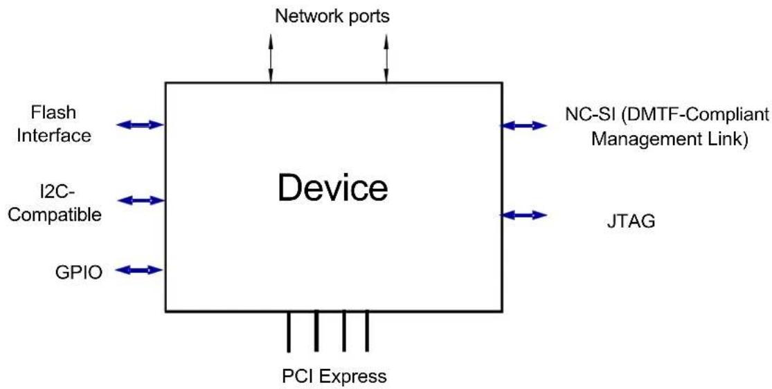
A high level illustration of the device is shown in Figure 1.
Figure 1: System Interface
flowchart
graph TD
    A["Device"] -->|Network ports| B["Network ports"]
    A --> C["PCI Express"]
    A --> D["I2C-Compatible"]
    A --> E["GPIO"]
    A --> F["Flash Interface"]
    A --> G["NC-SI (DMTF-Compliant Management Link)"]
    A --> H["JTAG"]
The device supports the following interfaces:
- Host Interfaces:
- PCI Express – See Section 1.2.1.1, “PCI Express,” on page 28
- NC-SI (DMTF-Compliant Management Link) – See Section 1.2.1.2, “NC-SI (DMTF-Compliant Management Link),” on page 28
- I²C-Compatible – See Section 1.2.1.3, “I2C-Compatible,” on page 28
• Network Interface – See Section 1.2.2, “Network Interface,” on page 29
- Flash Interface – This interface enables the HCA to perform the following:
- Boot from a non-volatile memory (Flash) residing on this interface
- Access the VPD data located on an NVMEM (Flash)
- Access the expansion ROM for host boot over the network
- GPIO – the device can drive or read these pins. These pins can be used for various functions such as controlling LEDs on adapter cards, or as interrupt inputs to the HCA which can respond by issuing an event on the host interface. See relevant Adapters Datasheets for details.
- JTAG – IEEE-compatible JTAG access port
1.2.1 Host Interface - PCI Express
A PCI Express 3.0 (Gen3) interface is used as the primary host interface for controlling the adapter (HCA) device. For example, this interface is used for boot configuration and for posting WR. During operation, the HCA moves data between the host interface and the network interface. The HCA uses the host interface to access control structures (for example, context tables), report completions, etc. Consumer application controls HCA operation through the host interface (for example, by ringing DoorBells).
1.2.1.1 PCI Express
The PCI Express interface is fully compatible with PCI-Express 3.0 specifications, implementing 16 lanes (x16) and delivering host memory access bandwidth of 16GBytes/sec in each direction. Various HCA products support lower number of lanes and lower signaling rate.
The software and management part of the PCI interface is discussed in Chapter 4, “PCI Interface” on page 47.
1.2.1.2 NC-SI (DMTF-Compliant Management Link)
NC-SI interface is a DMTF-compliant interface used to connect the device to an external Baseboard Management Controller (BMC). The device supports NC-SI version 2.0. Please contact Mellanox Technologies for more details.
The I ^2 C-compatible interface is designed to enable out-of-band access to the device, chassis management (IBML/SMBUS), and is used for HW debug. This interface is also designed to enable Mellanox debug tools to access the device, even in the event of other interfaces being down. The adapter device can be either a master or a slave on this interface (slave address is 0x48), and can support two different I ^2 C-compatible interfaces for redundancy/fault tolerance.
1.2.2 Network Interface
The network interface is comprised of 4 or 8 high-speed SERDES lanes running at up to 25Gb/s each. Utilizing these SERDES lanes, the HCA provides one or two 4X network ports. Each network port can use one, two or four lanes. Single-lane port configuration can use any lane. Multilane port configuration is supported on top of pairs (2X) or quads (4X) of SERDES lanes. Depending on the number of port lanes and lane speed configuration, each network port can run at 10, 25, 40, 50, 56 or 100Gb/s.
2 Operational Overview
This chapter provides an overview of the device operation, describing the data structures and control mechanisms of the device in general.
The device operation is described in the following sections:
• Section 2.1, “Software Interface,” on page 30
• Section 2.2, “HCA Configuration,” on page 30
• Section 2.3, “HCA Operation,” on page 30
2.1 Software Interface
The device can be accessed by system and application software in the following ways:
- Through the PCI configuration interface. This access type is used during the PCI Express fabric enumeration to configure the device.
- Through the HCA Configuration Registers that are accessed through memory BAR0 (see Chapter 4, "PCI Interface" on page 47). The software initializes the device and configures basic device capabilities at boot using this interface.
- Through user-level access to the HCA hardware (kernel bypass), using the User Access Region (UAR), as described in Section 7.2, "User Access Region (UAR)," on page 63.
2.2 HCA Configuration
At initialization, the device is configured through an HCA command queue (see Section 7.14.1, "HCA Command Queue," on page 145) and HCA registers. At this stage, the device capabilities (amount of resources to be supported), port capabilities and HCA resources are configured.
The HCA registers (UAR/DoorBells and initialization segment) are mapped to physical memory space. The mapping is provided through a standard PCI BAR/LIMIT mechanism. For more details, please refer to “PCI Interface” on page 47.
The command interface is used for general HCA device configuration. For more details, please refer to Section 7.14, "Command Interface," on page 145.
2.3 HCA Operation
After the HCA is initialized and opened, the host software supports send and receive data transfers through Work Requests (WRs) posted to Work Queues (WQs). Each WQ contains a Send Work Queue (SQ) for posted send requests, and a Receive Work Queue (RQ) for posted receive requests (see Chapter 7, "Software Interface" on page 62). The WR is posted as a Work Queue Entry (WQE) to an SQ/RQ. These WQEs can either cause data to be transmitted or received. WQEs are essentially descriptors that control the source and destination of data movement.
WQEs that transmit data from the HCA local memory can include a “gather” list. This “gather” list points to a set of memory buffers from which to assemble the outgoing message or contain immediate data to be sent. The RQ also has a “scatter” list included in posted WQEs to indicate memory buffers to be used for placing the received send payloads.
Data transfer is initiated by posting a descriptor to an SQ and ringing the respective DoorBell. Once the DoorBell has been rung on an SQ, the HCA initiates execution of the send descriptor,
reading the descriptor and executing it according to the descriptor's opcode - data transfer, memory registration and so on.
After a descriptor is executed and the message is completed, the HCA will post an entry to the corresponding Completion Queue (CQ). Multiple WQs can report their completions to the same CQ; the CQ number to report the completions is specified for each WQ at its initialization. The HCA stores a WQE identifier in the CQ.
2.3.1 Work Queues
Mainstream operations (send/receive data, bind and so on) are posted to WQs by the application SW. The Work Queue is accessible directly by the application program to post Work Requests to the HCA. Each Work Queue Element (WQE) represents a single Work Request. The Work Requests posted to WQs are executed by the HCA in the order that they are posted. Work Request is posted to the HCA by writing a list of one or more WQEs to the WQ and ringing the DoorBell which notifies the HCA that the request has been posted. For more details, please refer to Section 7.4, "Work Queues," on page 69.
2.3.2 Completion Queues and Completion Events
The HCA supports up to 16M CQs and enables reporting the completion of send or receive requests to different CQs. Multiple WQs can report their completions to the same CQ, maintaining many-to-one relations between WQs and CQs.
Events (and possibly a subsequent interrupt) can be registered for a CQ and are generated when a Completion Queue Element (CQE) is placed on that queue.
For more details, please refer to Section 7.12, "Completion Queues," on page 115.
2.3.3 Event Queues
Events generated by hardware are posted to Event Queues (EQs). The EQ is a memory-resident circular buffer used by hardware to write event cause information for consumption by the host software. HCA has multiple sources that can generate events (completion events, asynchronous events/errors). Once an event is generated internally, it can be reported to the host software via the Event Queue mechanism. When event reporting is enabled, event cause information is written by hardware to the EQ when the event occurs. If EQ is armed (that is, at least one event has been written to EQ), HW will subsequently generate an interrupt on the device interface (send an MSI-X message or assert the pin) as configured in the EQ.
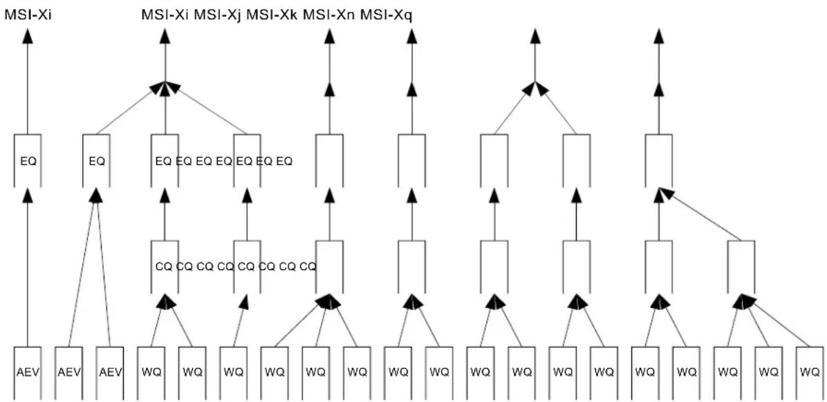
Each one of the HCA EQs can be associated with a different event handler on the host. The HCA supports multiple EQs designed to enable de-multiplexing of events to different consumers on the host. For example, completion reports can be reported to different EQs, based on the CQ that reports the event. Each CQ can be configured to report its events to a particular EQ; multiple CQs can report events to the same EQ. A completion event generated on the CQ may cause an event to be generated on the EQ that a certain CQ is mapped to.
In a virtual environment, EQs can be exported to the guest Virtual Machine (VM), and the kernel driver in the guest VM will control the EQ. HCA HW enforces protection and isolation between EQs.
For more details, please refer to Section 7.13, "Events and Interrupts," on page 133.
2.3.3.1 Interrupts
The HCA supports multiple means of generating interrupts - asserting a pin on its physical interface, emulating interrupt pin assertion on the host link (PCI) or generating Message Signaled Interrupts (MSI/MSI-X), enabling software to de-multiplex interrupts to different host consumers.
Each EQ can be configured to generate an interrupt when an EQE is posted to that EQ. Multiple EQs can be mapped to the same interrupt vector (MSI-X) maintaining many-to-one relations between EQs and interrupts.
The relations between WQs, CQs, EQs and different interrupt messages (MSIX vectors) is shown in Figure 2.
Figure 2: WQs, CQs, EQs and Interrupts Relations
flowchart
graph TD
    A["MSI-Xi"] --> B["EQ"]
    A --> C["EQ"]
    A --> D["MSI-Xj"]
    A --> E["MSI-Xk"]
    A --> F["MSI-Xn"]
    A --> G["MSI-Xq"]
    H["AEV"] --> I["AEV"]
    J["AEV"] --> K["AEV"]
    L["WQ"] --> M["WQ"]
    N["CQ"] --> O["CQ"]
    P["CQ"] --> Q["CQ"]
    R["CQ"] --> S["CQ"]
    T["WQ"] --> U["WQ"]
    V["WQ"] --> W["WQ"]
    X["WQ"] --> Y["WQ"]
    Z["WQ"] --> AA["WQ"]
    AB["WQ"] --> AC["WQ"]
Asynchronous events - like link state change or various errors - can also cause an event to be posted and an interrupt to be asserted. Each asynchronous event type can be mapped to a specific EQ and optionally generate an interrupt. Hardware does not prevent mapping synchronous and asynchronous events to the same EQ. The user should use common sense while configuring a device and use distinct EQs for asynchronous events.
2.3.4 HCA Memory Resources
Memory structures controlling HCA operation reside in the host memory allocated for the HCA by the host software. This memory - called Interconnect Context Memory (ICM) - is allocated by SW upon HCA request (in page-size chunks) and passed to HCA ownership. From that point on, SW should not access this memory until it is explicitly passed back to SW ownership by the HCA. Once given to the HCA, the HCA manages and uses this memory at its own discretion. For details see “Interconnect Context Memory” on page 52.
The amount of ICM memory used depends on the amount of HCA resources that will be used as in the following:
- Address Translation Tables - control structures in ICM memory allocated by the HCA for every memory key
- HCA Control Objects (Contexts) - control HCA operation and are managed by the HCA in its ICM
- User Access Region - a memory region that can be mapped directly to an un-trusted application by the OS and can be addressed by non-privileged code
For more details, please refer to “Memory Resources and Utilization” on page 52.
3 Networking and Stateless Offloads
This chapter covers the networking services provided by the device. Networking services include mechanisms for sending Ethernet frames over Ethernet media.
3.1 Networking Transport Objects
3.1.1 Overview
The adapter device uses the following transport objects (detailed in Chapter 7, “Software Interface” on page 62) for processing ingress/egress traffic:
- Flow Table - See Section 7.11
- Transport Interface Send (TIS) - See Section 7.6
- Transport Interface Receive (TIR) - See Section 7.5
- Send Queue (SQ) - See Section 7.9
- Receive Queue (RQ) - See Section 7.7
- Receive Memory Pool (RMP) - See Section 7.10
• Completion Queue (CQ) - See Section 7.12
• Event Queue (EQ) - See Section 7.13
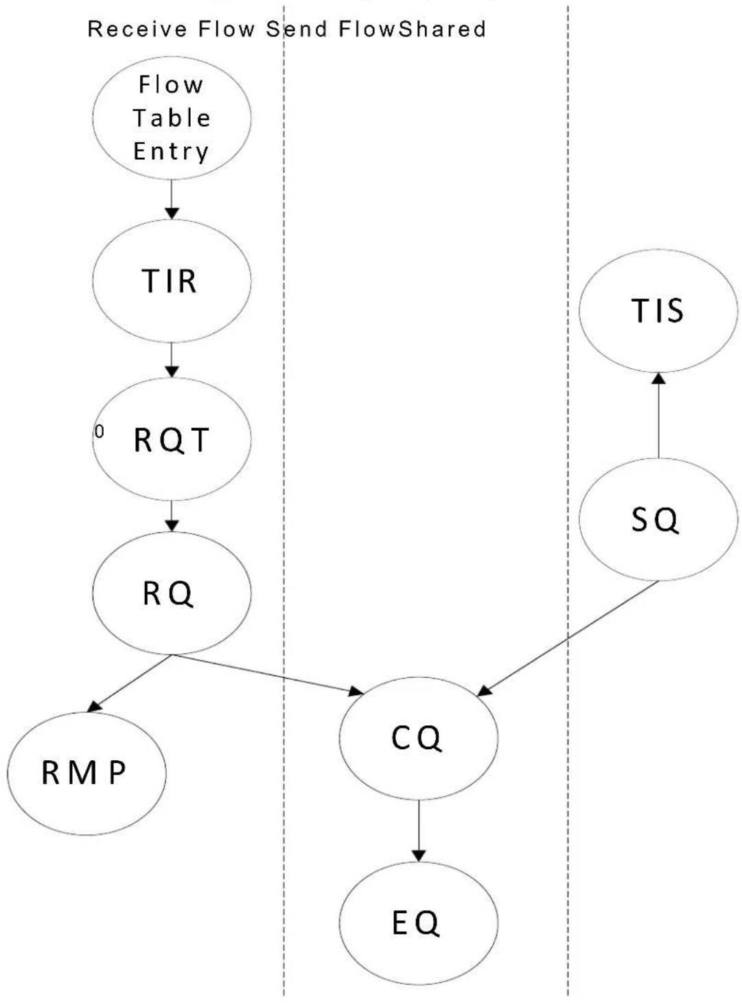
Figure 3 summarizes the various objects and the relationships between them. An arrow denotes an object pointing to n other objects whereas the n is specified on the edge of the arrow.
Note: SQ and RQ can point to the same or to a different CQ.
Figure 3: Networking Transport Objects
flowchart
graph TD
    A["Flow Table Entry"] --> B["TIR"]
    B --> C["RQT"]
    C --> D["RQ"]
    D --> E["RMP"]
    D --> F["CQ"]
    F --> G["EQ"]
    H["TIS"] --> I["SQ"]
    I --> F
    style A fill:#f9f,stroke:#333
    style B fill:#ccf,stroke:#333
    style C fill:#cfc,stroke:#333
    style D fill:#fcc,stroke:#333
    style E fill:#cff,stroke:#333
    style F fill:#ffc,stroke:#333
    style G fill:#cfc,stroke:#333
    style H fill:#fcc,stroke:#333
    style I fill:#cfc,stroke:#333
    style_J["Receive Flow Send FlowShared"]
As the diagram is shown for simplicity, it is imperative to explain the many to many relationships that are beyond the diagram. For example - two TIRs may point to the same or different RQs and
two completely different RQs or SQs (from same or other TIS/TIRs) can point to the same CQ or the same RMP.
3.2 Networking Services Usage
3.2.1 Ethernet
The basic Ethernet driver flow is summarized in the following bullets:
- Driver load
- Check device capabilities for Ethernet offload support through the command QUERY_HCA_CAP.
- Establish transmit rings:
- Allocate interrupts, create Event Queues and Completion Queues. Usually one interrupt, one Event Queue and one Completion Queue are created per CPU core.
- Create Transport Interface Send (TIS) objects. Usually one TIS is created per priority.
- Create Send Queues (SQ) objects for sending packets and associate with TIS. Usually, Send Queues are allocated per CPU, per priority. Note that this implies a many to one relationship between SQs and CQs.
- Establish receive rings:
- Allocate interrupts, create Event Queues and Completion Queues. Usually, one interrupt, one Event Queue and one Completion Queue is created per CPU core.
- Create Receive Queues (RQ) objects for receiving packets and associate with TIR (or RQT in case of indirection usage, then TIR points to RQT which point to RQs). Usually, Receive Queues are allocated per CPU.
- Create Transport Interface Receive (TIR) objects. Associate TIR objects with the respective RQ objects.
- F l o w T a b l e :
- Configure the Flow Table to point to the relevant TIR objects.
- Transmit Data Path:
- Post send Work Request on the TX Work Queue buffer and ring doorbell.
- Buffers can be released when CQE is reported.
- Interrupt and event reporting can be controlled through the CQ and the EQ.
- Receive Data Path:
- Post receive Work Request on the RX Work Queue buffer and ring doorbell.
- Reported CQEs indicate incoming packets including stateless offload indications.
- Interrupt and event reporting can be controlled through the CQ and the EQ.
- Driver tear-down:
- Remove Flow Table entries.
- Destroy receive rings:
- Destroy RQs, RQTs and TIRs.
- Destroy the associated CQs, EQs and interrupts.
- Destroy transmit rings:
- Destroy TIS objects and SQs.
- Destroy the associated CQs, EQs and interrupts.
3.3 Stateless Offloads
The device supports multiple Stateless Offloads for Ethernet. The Stateless Offloads listed in this section refer to offloads for device drivers running on bare metal device. Stateless Offloads include the following capabilities:
- Checksum Offload
• Large Send Offloads - Receive Side Scaling
- Transmit Side Scaling
- Interrupt Moderation
• Large Receive Offloads
• VLAN insertion and stripping - Flow Steering at layers 2, 3 and 4
- Packet padding (TX)
Start of Packet Padding (RX) and End of Packet Padding (RX) adapter stateless offloads are supported for the following scenarios:
- IPv4 and IPv6 packets
- Layer 2: Ethernet
3.3.1 Checksum Offload
The device supports calculation of checksum on transmitted packets and validation of received packets checksum. The adapter device offloads IPv4 checksum (L3) and TCP/UDP checksum (L4). Checksum calculation is supported for TCP/UDP running over IPv4 and IPv6.
Checksum offload support is reported through the csum_cap bit. See Section 12.3.3.2, "Networking Offload Capabilities," on page 202.
Transmit checksum offload is supported through WQE checksum bits as described in Section 7.4.4.1, "Send WQE Format," on page 75. Note that for TCP/UDP, the device does not require any pseudo header checksum calculation, and the value placed in TCP/UDP checksum is ignored by the device when performing the calculation.
Note that UDP/TCP transmit checksum calculation is not supported for IPv6 packets with routing extension header and for IPv4 packets with LSRR and SSRR IPv4 options.
Receive checksum offload is reported through CQE checksum bits as described in Section 7.12.1.1, "CQE Format," on page 118. The relevant CQE checksum bits are:
- l4_ok, l3_ok - indicate whether checksum calculation of the packet was okay
- Checksum - this field holds 1's complement 16-bit sum of the part of the packet and is summarized in Table 4. It helps software to calculate checksum on the packet in exceptional cases without the need to checksum all the packet payload by only calculating incrementally.
Table 4 summarizes the Checksum field behavior in the CQE.
Table 4 - CQE Checksum Behavior
| CQE Indication | Checksum Field Comment | |||
| l3_hdr_type | Tunneling | LRO Performed | ||
| Ipv4/Ipv6 | no no Calculated IP header and | IP Payload Checksum. | IP packet (IP only, TCP/UDP...) | |
| Ipv4/Ipv6 | no | yes | Checksum of the merged TCP segment payload. | TCP LRO message |
| None | no | no | invalid | Unrecognized packet, non IP |
3.3.2 Large Send Offload (LSO)
The adapter device supports Large Send Offload on transmitted TCP packets over IPv4 and IPv6. Large Send Offload enables the software to prepare a large TCP message for sending with a header template which is updated automatically for every generated segment. The device segments the large TCP message into multiple TCP segments. Per each such segment, device updates the header template accordingly, and then transmits these segments into the wire. At the end, a single completion (CQE) can be reported. The device's LSO is compatible with NDIS LSOv2 specification.
Large Send offload support is reported through the QUERY_HCA command through the max_l-so_cap field.
Large Send Offload is supported through WQE Large Send Offload opcode (see Section 7.4.4.1.1, "Ctrl Segment," on page 75).
3.3.3 Receive Side Scaling (RSS)
The adapter device supports Receive Side Scaling (RSS) capability. RSS spreads incoming traffic across multiple rings which can be further redirected to different CPU cores to better spread incoming loads. The adapter's RSS is compatible with the NDIS RSS specification.
RSS is implemented through two mechanisms: Flow Table and TIRs. Flow Table rules classify packets and deliver a specific traffic classes (e.g. TCP/UDP, IP only) to dedicated TIRs. TIRs of type Indirect are responsible for spreading the traffic which they receive from Flow Table and which belongs to specific traffic classes. Default RSS RQ can be supported by opening a dedicated TIR of the type Direct associated with a default RQ and configuring Flow Table to deliver to that “default” TIR all the traffic classes which should be delivered to the default RQ instead of being spread.
This allows supporting different RSS spreading modes for different traffic classes. For example, Flow Table rules can deliver all TCP IPv4 packets to TIR which spreads using
For more details, please refer to Section 7.11, "Flow Table," on page 108.
The actual support for RSS is reported through the HCA_CAP.rss_ind_tbl_cap.
3.3.3.1 TIR Spreading Traffic Mechanism
TIR context, with dispatcher type Indirect, selects a destination RQ based on selected packet fields. The TIR uses a configurable hash function and calculates a hash value based on the selected packet fields. TIR context selects a packet field according to rx_hash_fields_selector_outer and rx_hash_fields_selector_inner fields that set which field must take part in RQ selection. Note that only packets which include the fields chosen by TIR's rx_hash_fields_selector_outer/rx_hash_fields_selector_inner must be delivered to this specified TIR. For example, if TCP destination/source port are selected, only packets with TCP destination/source ports (UDP/TCP) should be delivered to that TIR. This can be achieved via proper Flow table rule configuration, which will ensure, for example, that only TCP/UDP packets are delivered to the TIR which uses TCP ports for RQ selection. The calculated hash value points to an indirection table (implemented with RQs Tables). The indirection table entries point to RQs for further handling of incoming packets. The RX hash value, selected fields and packet types are reported to the CQE. For more details related to TIR object, refer to Table 45, "TIR Context Fields," on page 86.
3.3.4 Transmit Side Scaling
Transmit side scaling enables simultaneous transmission of packets on multiple descriptor rings from multiple CPU cores. To achieve this, more than one SQ should be created. Multiple SQs can be attached to the same TIS.
3.3.5 Interrupt Moderation
Interrupt moderation can be achieved by controlling the EQ generation by CQs. This mechanism is explained in detail in Section 7.13.14, “Completion Event Moderation,” on page 143.
3.3.6 Large Receive Offload (LRO)
3.3.6.1 LRO Introduction and Device Capabilities
The device supports Large Receive Offload (LRO) for TCP streams. The implementation is fully compatible with NDIS Receive Segment Coalescing (RSC).
LRO capabilities can be queried through the QUERY_HCA_CAP command and is reflected through the following bits (see Section 12.3.3, "QUERY_HCA_CAP – Query Device Capabilities," on page 194):
- lro_cap - indicates LRO support
- lro_psh_flag, lro_time_stamp - indicate LRO support for segments with PSH flag and with the TCP timestamp option
- lro_min_mss_size - the minimal size of TCP segment required for coalescing
- lro_timer_supported_periods array - lists the supported LRO timer periods
LRO can be configured per TIR when the TIR is created through the CREATE_TIR command. The LRO parameters can be dynamically updated on a TIR using the MODIFY_TIR command, which can also turn on and turn off the LRO.
When a TIR that is enabled for LRO is destroyed (DESTROY_TIR), the device first completes all outstanding LRO sessions on that TIR and generates completions (CQEs). Only then does the DESTROY_TIR command complete. Similarly, when modifying a TIR (MODIFY_TIR) to disable LRO, the device first completes all outstanding LRO sessions on the TIR.
When enabled for LRO, the TIR extracts LRO Flow IDs for incoming packets. LRO Flow ID is based on connection 6 tuple: VLAN ID, Source IP, Destination IP, Source TCP Port, Destination TCP Port and TCP transport. Packets that use the same LRO Flow ID are candidates for LRO coalescing.
3.3.6.2 LRO Session Creation
LRO coalescing is performed using LRO sessions. Sessions can be created and terminated dynamically by the device. While a session is open, segments using the same LRO Flow ID can be coalesced within the session.
A session is created when all the following conditions are met:
- LRO is enabled when creating TIR context by setting lro_enable_mask and other lro parameters
• T C P P a c k e t - No LLC/SNAP
- The HW has available resources for a new LRO session
- Packet validation is OK, e.g. packet is not malformed, TCP/IP checksum is OK, etc.
- TCP flags are clear: SYN, URG, RST, FIN, NS and Reserved flags
- When HCA_CAP.lro_psh_flag is disabled, PSH flag should also be clear
- No TCP options other than timestamp
- When HCA_CAP.lro_time_stamp is disabled, TCP timestamp option must not appear
- No IPv4 options or IPv6 extension headers
• The packet is not an IP fragment - Segment TCP payload size is >= HCA_CAP.lro_min_mss_size
- Note: lro_min_mss_size > 0 and therefore pure ACKs are never merged
• LRO Flow ID does not have an open LRO session
3.3.6.3 LRO Session Termination
An LRO session is terminated when one of the below conditions is met:
- LRO timer expiration
- Not enough space in receive WQE
• TIR destruction or update (e.g. LRO disable)
- Incoming packets that belong to the LRO session and meet any of the conditions which are described below:
- Invalid TCP/IP checksum
- One of the flags is enabled: SYN, URG, RST, FIN, NS and reserved TCP flags
- PSH flag is enabled and HCA_CAP.lro_psh_flag = 0
- The packet contains TCP options other than timestamp
- When HCA_CAP.Iro_time_stamp is disabled and TCP timestamp option appears
- The packet contains IPv4 options or IPv6 extension headers
- Segment TCP payload size is <HCA_CAP.lro_min_mss_size
-
Out of order segment (TCP sequence number doesn't match the expected sequence number)
-
Coalescing the currently arrived segment will exceed TIR's maximum IP length(*)
- Segment contains a timestamp option, HCA_CAP.lro_time_stamp == 1, and one of the following conditions is met(*):
- The previous segment does not contain the timestamp option
- Timestamp Value of the new segments < Timestamp Value of the LRO session
- The segment does not contain a timestamp option but the previous segments contain a timestamp option (*)
- The segment contains a different value for the ECN flags (ECE and CWR) in the TCP header. The segment contains a different value for the ECN field (ECT, CE) in the IP header comparing to the previous segment (*)
- IP field of the incoming packet does not match the IP fields of the previous packets besides the following fields: TTL/Hop Limit, IPv4.Checksum, IPv4.Total Length and IPv4.Identification/IPv6iczPayload Length
• The packet is an IP fragment.
When the session is terminated, a completion is generated accordingly to reflect the data that was already coalesced on the LRO session. When session termination happens as a result of segment arrival, this segment is not included as part of the “already coalesced data.” After the completion generation, the new segment can be a candidate for a new session or generate an immediate completion. If the session was terminated as a result of timestamp mismatch or ECN mismatch (last four cases of incoming packet, marked with asterisk (*) in the above list), then the new segment can be a candidate for creation of a new session (see Section 3.3.6.2, “LRO Session Creation,” on page 40). Otherwise, the new segment generates a regular completion as a standalone incoming packet.
3.3.6.4 Merging New Segments Into Existing LRO Session
When a new segment arrives with an LRO Flow ID of an existing LRO session, then the segment is a candidate for coalescing into an LRO session. The merge takes place if all the below conditions are met:
- All conditions mentioned in Section 3.3.6.2, “LRO Session Creation,” on page 40
- If the segment contains a timestamp option and:
- the previous segment contained a timestamp option
- the incoming segment timestamp value is ≥slant the timestamp previous segment timestamp
- If the incoming segment does not contain a timestamp option and the previous segment did not contain a timestamp option
- Matching on all IP fields, except: TTL/Hop Limit, IPv4.Checksum, IPv4. Total Length and IPv4.Identification/IPv6iczPayload Length
- Matching on ECN flags (ECE and CWR) in the TCP header
- Matching on TCP Sequence Number
- Coalescing the new segment will not exhaust TIR lro_max_ip_payload_size
- Please note that the RQ WQE should be large enough to contain the merged segments, otherwise the LRO session is flushed and completion with error is generated.
3.3.6.5 LRO Packet Scatter to Memory
LRO session is scattered into memory according to the relevant RQ/RMP pointed to by the TIR. The first segment in the LRO session is scattered as is to memory according to the RQ configuration. For example, when VLAN stripping is configured, then the VLAN is stripped prior to scattering the first segment into memory. CQE is not reported. Subsequent segments that are merged into an opened LRO session continue to utilize that WQE. Therefore that WQE has to be large enough to contain the lro_max_ip_payload_size (as configured in the TIR) and in addition the IP headers and the L2 header.
Subsequent segments that are added to the LRO WQE are adding only the TCP payload, thus creating a big TCP packet (one header with coalesced TCP payload) that comprises all coalesced segments. The segments do not update the TCP header of the first segment (the one that created the LRO session). The relevant TCP fields, e.g. latest TCP Window Size, are reflected in the CQE that is generated when the LRO session is terminated.
It is the software responsibility to fix the original TCP and IP headers based on the CQE values. To do this, software can check the lro_num_seg in the CQE and if non-zero, then TCP fields should be updated.
Note that additional information for debug, tuning and statistics is reported to the LRO CQE, e.g. the reason for the LRO session termination.
3.3.6.6 LRO CQE Fields Summary
This section summarizes LRO related CQE fields and their usage. SW needs some of these fields in order to update the TCP/IP headers to correctly reflect the arrived data and connection state (for example TCP Window size or IPv4 TTL field). These fields should be carefully updated according to the requirements and needs of the relevant SW framework.
Table 5 summarizes the LRO fields in CQEs.
Table 5 - LRO CQE Fields Summary
| Field Name Field Value Description | ||
| Iro_tcp_psh One of the packets | in the session had a TCP PUSH flag set. | If set, SW must enable the PSH flag in the header of the merged TCP segment. Valid only for LRO packets (lro_num_seg field not clear). |
| Iro_abrt | Abort coalescing reason. | Can be used in order to collect LRO statistic. Valid only for LRO packets (lro_num_seg field not clear). |
| Iro_dup_ack_cnt Number of duplicate acknowledgment that were encountered while creating the coalesced segment. | In some environments driver must report this number as OOB info to TCP/IP stack. Valid only for LRO packets (lro_num_seg field not clear). This field should be always zero. | |
| Iro_min_ttl The minimum HopLimit / Time-ToLive of all packets in this merged segment. | SW must update the IPv4 Time to live or IPv6 Hop limit fields according this field. Valid only for LRO packets (lro_num_seg field not clear). | |
| Iro_tcp_win TCP window of the last packet in the coalesced segment. | SW must insert this value into the TCP header of the merged packet. | |
Table 5 - LRO CQE Fields Summary
| Field Name Field Value Description | ||
| lro_ack_seq_num LRO acknowledgment sequence number (last packet in session). | SW must insert this value into the TCP header of the merged packet.Should be ignored if l4_hdr_type != 3 or 4. Valid only for LRO packets (lro_num_seg field not clear). | |
| Checksum The checksum field for coalesced TCP segments. | For LRO (lro_num_seg field not clear), this field covers TCP header + TCP payload of all merged packets (without TCP pseudo header).If SW wants/needs to calculate and fix checksum of merged TCP header and payload it can use this field. This field helps software calculate checksum on the merged packet without the need to checksum all the packet payload by only calculating incrementally.Please note that the final checksum should be calculated after TCP header is fixed.Please note that this field is not useful for IPv4 Checksum calculation.Also please note that before recalculating and fixing IPv4 Checksum IPv4 header must be first fixed so it will reflect the correctly the merged segment. | |
| lro_num_seg Number of coalesced segments of LRO. | 0 - when LRO was not performed.1 - when HW aggregated just a single packet.Greater than 1 - when HW aggregated more than a single packet. | |
| byte_cnt | Byte count of data transferred. | For LRO messages (lro_num_seg field not clear): the total length of messages is specified.For example, for ETH packets the byte count starts from the MAC header.This field should be used in order to fix the IPv4.Total length or IPv6 Payload length fields. |
| lro_timestamp_is_valid Indicates that CQE's timestamp field holds LRO timestamp instead of regular timestamp CQE field. | When this bit is set lro_timestamp_value/time-stamp_h and lro_timestamp_echo/timestamp_l holds LRO timestamp values. | |
| lro_timestamp_value/time-stamp_h | This field holds the Timestamp Value (TSval) field of the header of the last coalesced segment. | This field holds the Timestamp Value (TSval) field of the header of the last coalesced segment only if lro_timestamp_is_valid bit is on.If this field is valid (as LRO timestamp), SW can choose to update the TS Value (TSval) field of TCP header. Please note that this is not always required/needed. Please refer to documentation of your SW framework for more details. |
| lro_timestamp_echo/time-stamp_1 | This field holds the Timestamp Echo Reply (TSccr) field of the header of the last coalesced segment. | This field holds the Timestamp Echo Reply (TSccr) of the header of the last coalesced segment only if: lro_timestamp_is_valid && (L4_hdr_type == 3 || L4_hdr_type == 4).If this field is valid (as LRO timestamp), SW can update TS Echo Reply (TSccr) field of the TCP header. |
Table 5 - LRO CQE Fields Summary
| Field Name Field Value Description | |
| L4_hdr_type | L4 Header typeIn some cases for LRO messages (lro_num_seg > 0), inside CQE, the <ACK> bit is enabled but inside the header the bit is disabled. This happens when in the header of the first segment, the <ACK> bit, was off but in one of the next merged segments this bit was on. So for LRO packet when L4_hdr_type == 4 or 3, SW must verify that the <ACK> bit inside the TCP header of the merged segment is enabled, before delivering the segment to the TCP/IP module.In addition this bit allows checking if lro_ack_seq_num and lro_timestamp_echo field are valid. |
3.3.7 VLAN Insertion/Stripping
The device offloads VLAN insertion and stripping for raw Ethernet frames.
VLAN insertion is performed by the driver, inlining the VLAN tag into the Ethernet frame headers in the WQE Eth Segment (see Section 7.4.4.1.2, “Eth Segment and Padding Segment,” on page 77).
VLAN Stripping is configured in RQ through the VLAN Stripping Disable (vsd) bit. When configured to perform VLAN Stripping, the device removes the VLAN tag from the incoming frames and reports it in the CQE fields.
For tunneled packets, both the outer and the inner VLANs can be manipulated through VLAN insertion offload, by inlining both outer and inner frame headers, but only the outer VLAN can be stripped by VLAN stripping offload.
The support for VLAN insertion and stripping is reported through the QUERY_HCA_CAP vlan_cap field.
3.3.8 Packet Padding (TX)
Ethernet packets shorter than 64 bytes are automatically padded by the device on transmission to 64 bytes by appending trailing zeros (before the FCS). Additionally, the last segment of an LSO packet, if shorter than 64B, is also automatically padded to 64B.
For encapsulated frames over Ethernet, the outer Ethernet packets are automatically padded by the device to 64 bytes. Inner frames are left untouched.
3.3.9 Start of Packet Padding (RX)
Note - This feature is supported only when HCA_CAP.start_pad==1.
Some root complex are able to optimize their performance when incoming data size is multiple full cache lines. The device can pad the beginning of incoming packets to full cache line such that the last upstream write generated by the incoming packet will be a full cache line.
Start of packet padding can be enabled by setting start_padding field in Data Segment of Receive WQE to 1. See Section 7.4.4.1.5, "Receive Data Segments," on page 83.
3.3.10 End of Packet Padding (RX)
Note - This feature is supported only when HCA_CAP.end_pad=1.
Some root complex are able to optimize their performance when incoming data is multiple full cache lines. The device can pad the ending of incoming packets to full cache line such that the last upstream write generated by the incoming packet, will be a full cache line. When padding incoming packets, the device will never go beyond the WQE scatter entry length.
To configure RQ to pad incoming packets, the end_padding_mode field should be configured in the RQ Context.
The end of packet padding byte count is not reported to the CQE generated. In other words, the byte_cnt field in the CQE reports the incoming message as received bytes and excludes the padding.
Cache line size, by default, is 64 bytes and can be configured to 128 bytes using HCA_CAP.cache_line_128byte in case it is supported.
3.4 Self-Loopback Control Using Transport Domains
Multiple consumers that coexist on the same NIC port can communicate via a local loopback mechanism. A consumer might want to send packets to other local consumers via loopback but block self-loopbacked packets. For this purpose, the device provides Transport Domain support which allows a consumer to define which set of TIS/TIRs belongs to it and control if local loopbacked packets generated by its TISs and delivered to its TIRs should be accepted or blocked. The Transport Domain support is indicated by HCA_CAP.log_max_transport_domain (see Table 144, "HCA Capabilities Layout," on page 196).
Transport Domains are allocated and released using DE/ALLOC_TRANSPORT_DOMAIN commands.
TIRs and TISs are associated with Transport Domain via TIR/TIS.transport_domain_id field and TIR. self_lb_en controls self-loopback behavior of the TIR.
3.5 Sniffer
The device deploys a sniffer mechanism, enabling the duplication of the packets to designated NIC root Flow Tables: one root Flow Table of type “NIC Sniffer RX” sniffs NIC’s incoming packets and one root Flow Table of type “NIC Sniffer TX” sniffs NIC’s sent packets. Sniffer root Flow Tables allow to create additional Flow Table chaining hierarchy, independent from the “main” NIC Flow Table configuration. This allows the Sniffer SW to manage its own Flow Table rules which are not dependent on the “original” Flow Table settings. In a sense, the sniffer is a silent “observer”; all packets are still delivered to their “original” destination when the sniffer function is enabled.
Sniffer Flow Tables must be handled as any other NIC Flow Table. Sniffer Flow Tables are managed via CREATE/DESTORY_FLOW_TABLE commands. See Section 12.14, "Flow Table Commands," on page 276.
If root Sniffer Flow Tables are not configured, HW does not perform packet replication for sniffing purpose.
Note: Enabling sniffer Flow Tables may have an adverse effect on the performance of the NIC.
Note: Loopbacked-by-NIC packets are delivered both to NIC TX Sniffer Flow Table and to NIC RX Sniffer Flow Table; i.e., when both RX and TX Sniffer Flow Tables are enabled, two copies of the loopbacked packet are captured by the Sniffer.
Figure 4: Sniffer Flow in ETH Port
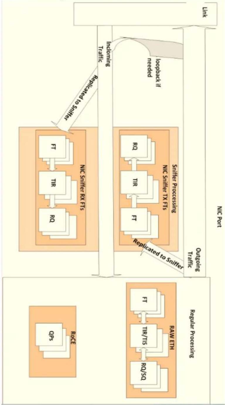
flowchart
graph TD
    A["NIC Port"] --> B["Link"]
    B --> C["Incloming Traffic"]
    C --> D["Loopback if needed"]
    D --> E["Replicated to Sniffer"]
    E --> F["NIC Sniffer RX FTs"]
    F --> G["FT"]
    F --> H["TIR"]
    F --> I["RQ"]
    F --> J["FT"]
    F --> K["TIR"]
    F --> L["FT"]
    F --> M["TIR/TIS"]
    F --> N["RO/SQL"]
    F --> O["ReqCE"]
    P["Regular Processing"] --> Q["Req"]
    P --> R["FT"]
    P --> S["TIR/TIS"]
    P --> T["RO/SQL"]
    P --> U["ReqCE"]
    V["Outgoing Traffic"] --> W["Replicated to Sniffer"]
    W --> X["TIR"]
    W --> Y["TIR"]
    W --> Z["FT"]
    W --> AA["TIR/TIS"]
    W --> AB["RO/SQL"]
    W --> AC["ReqCE"]
4 PCI Interface
The device accesses the host processor through a 16x PCI Express 3.0 bus, capable of consuming/driving data at a rate of 16Gbyte/sec full-duplex.
The device is capable of presenting up to 16 physical functions and 256 virtual functions. Each physical and virtual function exposes PCI type0 configuration header.
Each function (be it physical or virtual) exposes a single BAR called HCA BAR - a prefetchable BAR used to post control data path commands. Both the initialization segment and the UAR pages are implemented on this BAR. This is Bar0 in the PCI header.
Format of the initialization segment is shown in “Initialization Segment” on page 48. Format of the UAR pages is shown in “User Access Region (UAR)” on page 63.
4.1 PCIe Compliance
The device is PCI Express 3.0 compliant. It supports the following features of the PCI Express 3.0:
- Optimized Buffer Flush/Fill (OBFF)
• Latency Tolerance Reporting (LTR) - Re-sizable BARs
• L1 Active State Power Management (ASPM) - ASPM Optionality
- Advanced Error Reporting
• Alternative Routing-ID Interpretation (ARI)
• ID-Based Ordering (IDO) - Extended Tag
• TLP Processing Hints (TPH)
• Steering Tags are not supported
The device also supports:
• 8.0 GT/s Receiver Impedance
• Precision Time Measurement (PTM)
- Readiness Notifications (RN)
The following features are supported in memory region granularity:
- No-snoop
- Relaxed ordering
- TPH - TLP processing hints
4.2 Capabilities Reporting
PCI Express® Base Specification defines a set of capabilities which should be reported when made available by the device. These capabilities are reported through a special structure of linked-list items. The first capability is pointed in offset 0x34 in the configuration space, and the last capability is indicated by setting its “next capability” pointer to 0x00.
The capabilities are defined in Appendix H of the PCI Express® Base Specification. PCIe additional capabilities (added on top of PCI) are described in Section 7.5 of the same specification.
The capabilities reported by the device are listed in Table 6.
Table 6 - PCI Capabilities Summary
| Name ID Value Description | ||
| Power 0x1 PCI Power Management InterfaceDefined by PCI Power management interface specification. | ||
| VPD 0x3 Vital Product Data (VPD)Defined in section 6.4 in Appendix I of PCI Local base specification, Revision 3.0 | ||
| PCI Express 0x10 PCI ExpressDefined in section 7.8 of PCI Express Base Specification, Revision 3.0 | ||
| MSI-X 0x11 MSI extension supportDefined in section 6.8 of PCI Local base specification, Revision 3.0 | ||
| MSI 0x5 Message Signalled Interrupts (MSI)Defined in section 6.8 of PCI Local base specification, Revision 3.0 |
4.3 Initialization Segment
The initialization segment is located at offset 0 of HCA BAR. The device uses this segment in the initialization flow (as described in Chapter 11, “Initialization and Teardown” on page 365), and to perform command doorbell as further described in Chapter 12, “Command Reference” on page 185.
Table 7 - Initialization Segment
| 31 | 30 | 29 | 28 | 27 | 26 | 25 | 24 | 23 | 22 | 21 | 20 | 19 | 18 | 17 | 16 | 15 | 14 | 13 | 12 | 11 | 10 | 9 | 8 | 7 | 6 | 5 | 4 | 3 | 2 | 1 | 0 | Offset |
| fw_rev_minor | fw_rev_major | 00h | ||||||||||||||||||||||||||||||
| cmd_interface_rev | fw_rev_subminor | 04h | ||||||||||||||||||||||||||||||
| 08h | ||||||||||||||||||||||||||||||||
| 0Ch | ||||||||||||||||||||||||||||||||
| cmdq_phy_addr[63:32] | 10h | |||||||||||||||||||||||||||||||
| cmdq_phy_addr[31:12] | nic_inter-face | log_cmdq_size | log_cmd-q_stride | 14h | ||||||||||||||||||||||||||||
| command DoorBell vector | 18h | |||||||||||||||||||||||||||||||
| 1Ch-IF8 | ||||||||||||||||||||||||||||||||
Table 7 - Initialization Segment
| 31 | 30 | 29 | 28 | 27 | 26 | 25 | 24 | 23 | 22 | 21 | 20 | 19 | 18 | 17 | 16 | 15 | 14 | 13 | 12 | 11 | 10 | 9 | 8 | 7 | 6 | 5 | 4 | 3 | 2 | 1 | 0 | Offset |
| initializing | nic_interface_-supported | 1FCh-200h-23Ch-240h | ||||||||||||||||||||||||||||||
| 244h-FFCh | ||||||||||||||||||||||||||||||||
| 1000h | ||||||||||||||||||||||||||||||||
| internal_timer_h | 1004h | |||||||||||||||||||||||||||||||
| internal_timer_l | 1008h | |||||||||||||||||||||||||||||||
| clear int | ||||||||||||||||||||||||||||||||
| health_syndrome health counter | 1010h | |||||||||||||||||||||||||||||||
| 1014h-2008h-200Ch | ||||||||||||||||||||||||||||||||
| 2010h-4008h | ||||||||||||||||||||||||||||||||
Table 8 - Initialization Segment Field Descriptions
| Offset Bits Name | Description Access | ||
| 0000h | 31:16 | fw_rev_minor | Firmware Revision - Minor |
| 15:0 | fw_rev_major | Firmware Revision - Major |
Table 8 - Initialization Segment Field Descriptions
| Offset | Bits | Name | Description | Access |
| 0004h | 31:16 | cmd_interface_rev | Command Interface Interpreter Revision IDThis number is bumped up every time a non-backward-compatible change is done for the command interface. | RO |
| 15:0 fw | _rev_subminor Firmware | Sub-minor version (Patch level) RO | ||
| 0010h 31 | :0 cmdq | -phy_addr[63:32] | Physical address of the command queue record.This field should not be modified after INIT_HCA until TEARDOWN_HCA. | RW |
| 0014h 31 | :12 cmdq | -phy_addr[31:12] | Physical address of the command queue record.This field should not be modified after INIT_HCA until TEARDOWN_HCA. | RW |
| 9:8 nic | interface NIC interface mode | 0x0: full_driver0x1: disabled | WO | |
| 7:4 log | cmdq_size Log number of cmdqs available RO | |||
| 3:0 | log_cmdq_stride | Stride between start of each cmdq | RO | |
| 0018h 31 | :0 command | and DoorBell vector | Bit per command in the cmdq. When the bit is set, when writing this vector to the device, the command is moved to HW ownership (HW need to execute the command). bit 0 is related to the command in offset 0 in the command queue etc.The valid bits in this vector are [number of commands-1..0]When driver is in No DRAM NIC mode, this field must not be written. | WO |
| 01FC 31 | initializing | 1 - device still in initializing state.0 - device is ready to receive commands. | RO | |
| 26:24 nic | interface_supported | Bitmask indicating which nic_interface modes are supported0: full_driver1: disabled | RO | |
| 1000h | 31:0 | internal_timer_h | MSBs of the current internal timer value. See Section 7.12.10, “CQE Timestamping,” on page 132 | RO |
| 1004h | 31:0 | internal_timer_l | LSBs of the current internal timer value.See Section 7.12.10, “CQE Timestamping,” on page 132. | RO |
| 100Ch | 0 | clear_int | Writing 1 to this register will clear the interrupt (will always use intA) | WO |
Table 8 - Initialization Segment Field Descriptions
| Offset | Bits | Name | Description | Access |
| 1010h 31:24 | health_syndrome Syndrome | 0x1: FW_INTERNAL_ERR - assert triggered in FW code0x7: DEAD_IRISC - Iris not responding0x8: HW_FATAL_ERR0x9: FW_CRC_ERR0xA: ICM_FETCH_PCI_ERR0xB: ICM_PAGE_ERR0xC: ASYNCHRONOUS_EQ_BUF_OVERRUN0xD: EQ_IN_ERR0xE: EQ_INV0xF: FFSER_ERR0x10: HIGH_TEMP_ERR | RO | |
4.4 Data Interface
4.4.1 PCIe Attributes
The device supports flexible configuration of PCIe cycle attributes. The PCIe cycles' attributes are configured for each Memory Key Context at its creation (see "MKey Context" on page 58). Those attributes are passed to the PCIe interface unit and to the PCIe packets. Note that for indirect address translation where multiple context accesses are involved during the address translation process, the attributes passed to the PCIe interface unit are bitwise OR of all attributes of MKCs involved in address translation.
5 Memory Resources and Utilization
To control its operation, the HCA uses various data structures (contexts) residing in system memory. The HCA requests memory pages from software and then uses those pages to manage these data structures.
The amount of memory to be used depends on the capabilities that the HCA is required to support. For example, the number of concurrently open RQs/SQs determines the amount of memory that is requested by the HCA for RQ/SQ related contexts.
Memory allocation can be done in chunks of system pages. However, for performance reasons it is desirable to allocate a physically contiguous chunk of host memory for the Interconnect Context Memory (ICM).
5.1 Interconnect Context Memory
ICM is host memory that is allocated for the exclusive use of the HCA. The HCA uses the ICM to maintain and manage its control objects. The ICM is allocated upon HCA request at initialization (see “Initialization” on page 365). When the HCA needs system memory, it requests memory allocation from software and the latter should then allocate memory pages and pass them to HCA ownership. Software should not access these HCA owned pages until the HCA returns their ownership to SW.
The HCA asks software to allocate or release memory pages by posting events. SW should respond to these events using the MANAGE_PAGES command, see Section 12.3.2, "MANAGE_PAGES - Driver Delivers Memory Pages for the Device Usage or Returns Pages," on page 191 for details. Moreover, the HCA manages an independent ICM for each PCI function, enabling to shut down individual PCI functions without impacting others.
5.2 Memory Resources
To control its operation, the HCA uses various data structures, residing in host memory. To help the system developer correctly configure the system memory resources, this section presents an overview of the device's data structures, and the memory resources required for HCA operation.
5.2.1 Address Translation Tables
Address translation tables are control structures in ICM allocated by the HCA for every memory key. These tables are used to translate virtual addresses to physical ones. They are programmed by software through the HCA command interface as well as by lightweight memory registration operations and are subsequently maintained by the HCA hardware.
For more details about address translation and protection please refer to “Address Translation and Protection” on page 54.
5.3 HCA Control Objects (Contexts)
The HCA operation is controlled by “context objects” that are managed by the HCA in its ICM. For more details about control objects, please refer to Chapter 7, “Software Interface” on page 62.
5.4 User Access Region
The HCA provides a memory region that can be mapped directly to an un-trusted application by the OS and can be addressed by non-privileged code. This region is used to allow unprivileged applications to access needed HCA resources, such as ringing DoorBells, from userspace. Each process should get a distinct page mapped to this region to access HCA for data path operation, thereby isolating HCA access between the processes.
For more details about User Access Region format and usage please refer to Section 7.2, “User Access Region (UAR),” on page 63.
6 Address Translation and Protection
Each memory request generated by the HCA undergoes address translation and protection checks as illustrated in Figure 5.
Figure 5: Address Translation Stages
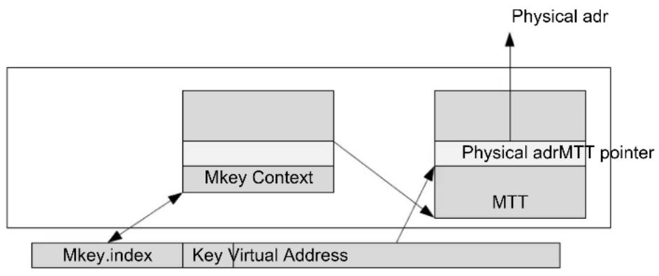
flowchart
graph TD
    A["Mkey.index"] --> B["Key Virtual Address"]
    B --> C["Physical adr"]
    C --> D["MTT"]
    D --> E["Physical adrMTT pointer"]
    E --> F["Mkey Context"]
    F --> G["Physical adr"]
    style A fill:#f9f,stroke:#333
    style B fill:#ccf,stroke:#333
    style C fill:#cfc,stroke:#333
    style D fill:#fcc,stroke:#333
    style E fill:#cff,stroke:#333
    style F fill:#ffc,stroke:#333
    style G fill:#cfc,stroke:#333
The device translates the given virtual address to a physical address using the given memory key as an address space identifier. Memory protection checks are done in this stage.
6.1 Virtual to Physical Address Translation and Protection Checks
Each memory request specifies a virtual address space identifier (Memory Key or MKey) and a virtual address within this address space. An MKey is a 32-bit address space identifier consisting of two fields - index and key. The Index field identifies the MKey. The key field can be altered by the application program for various reasons such as a generation identifier when an MKey is reused. The logical structure of an MKey is shown in Figure 6.
Figure 6: MKey Structure
31870
| Index Key |
Address translation performs the bulk of the work. A memory region context is retrieved using the MKey given in the memory operation. Internally, MKeys are managed in the Memory Protection Table (MPT).
Once a memory region context is located, the memory operation is validated against the parameters in the memory region context:
- Boundary check – The virtual address and length of access are validated against the region/window boundaries.
- Operation check – Operation (read/write) and location (local/remote) are validated against the memory region/window rights.
If all the previous validations passed, then the virtual address is translated into a physical address.
The memory region's base address is subtracted from the Virtual Address (VA) given in the operation, giving an offset into the memory region. With this offset, one of the memory translation
table entries (MTT) associated with the memory key context can be selected. The type of memory region will determine what the MTT points to and hence how to pick the right one. There are 2 different types of memory regions:
- Direct mode: Each MTT entry translates a naturally-aligned page. The page size is specified in the MKey context; HW supports page sizes from 512 bytes to 2 gigabytes. The page size must be a power of two. In this mode, a physical address may now be calculated. The offset from the previous step is divided by the size of each MTT entry, giving the correct MTT entry. The remainder of this division is added to the physical address indicated in the MTT entry giving the physical address. If necessary, spanning multiple MTT entries is done automatically using the same process.
- Indirect mode: Each KLM entry specifies another memory key, an address within the address space specified by this memory key and the length in bytes of the segment represented by this KLM entry. The KLM entries for the memory region are “walked” until the correct entry for the given offset is found. The remainder of the offset is added to the address in the KLM entry and the entire process is repeated. HW protects itself from the possibility of infinite recursion. Note that memory protection checks must pass on ALL indirect MKeys as well as the direct MKey, or the operation will fail. For executing memory operation, the appropriate access-right (for example, local write) should be in all related MKeys. Indirect memory regions allow the combination of multiple sparse memory buffers to a single virtually-contiguous memory buffer that can be used for I/O operation. See “Address Translation Indirection” on page 56 for details.
The state machine flow of address translation is shown in Figure 7.
Figure 7: Address Translation State Machine
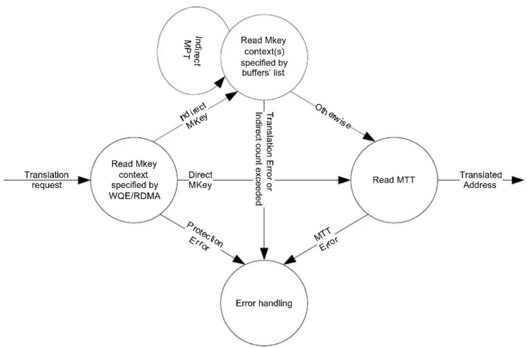
flowchart
graph TD
    A["Translation request"] --> B["Read Mkey context specified by WQE/RDMA"]
    B --> C["Direct MKey"]
    B --> D["Protection Error"]
    B --> E["Error handling"]
    F["Read Mkey context(s) specified by buffers' list"] --> G["Indirect MKey"]
    F --> H["Translation Error or Indirect count exceeded"]
    F --> I["Otherwise"]
    F --> J["MTT Error"]
    K["Read MTT"] --> L["Translated Address"]
    E --> J
    J --> L
6.1.1 Address Translation Indirection
The device has extended memory management functionality that enables specifying an arbitrary list of memory buffers (scatter/gather list) as a virtual address space. The memory translation table (MTT) entries associated with a given memory key can be a list of buffer pointers in a structure similar to the scatter/gather list used in WQEs. When used this way, the MKey is called an indirect MKey. The size and alignment of each individual buffer (MTT entry) are not constrained. When an indirect MKey is used, the address given in the memory reference specifies an address within the virtual address space defined by the list of memory buffers (MTT entries) of the MKey. In turn, the given address identifies an individual pointer(s) to be used for the next step in the address translation process. The next step in address translation uses the memkey and virtual address of the pointer identified in the first step. See Section 6.1, “Virtual to Physical Address Translation and Protection Checks,” on page 54 for a detailed description of address translation calculation. A simple case of one-step indirect address translation flow is illustrated in Figure 8.
Figure 8: Address Translation Flow Example
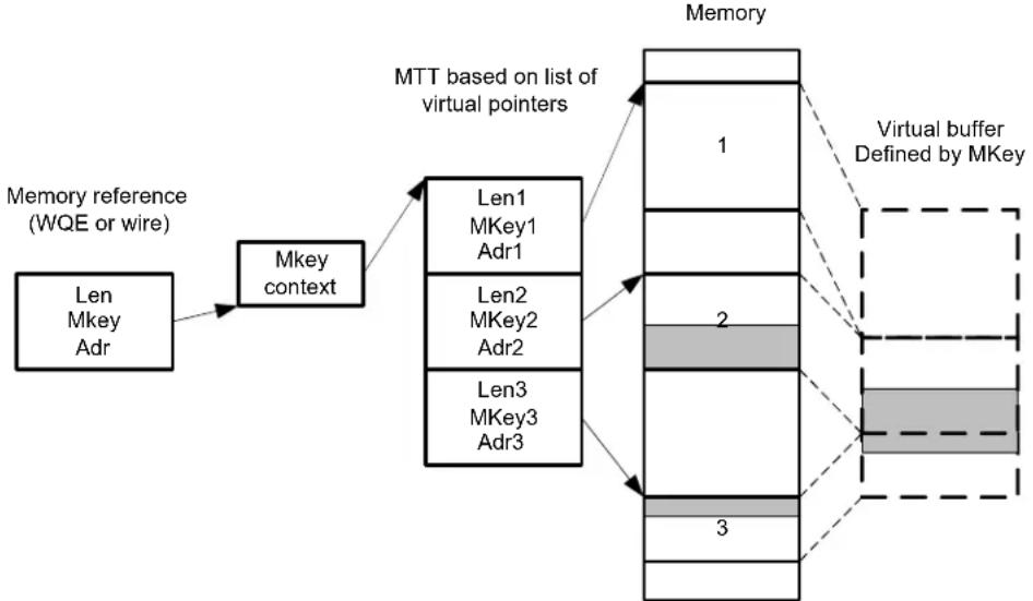
flowchart
graph TD
    A["Len MKey Adr"] --> B["Mkey context"]
    B --> C["Len1 MKey1 Adr1"]
    B --> D["Len2 MKey2 Adr2"]
    B --> E["Len3 MKey3 Adr3"]
    C --> F["MTT based on list of virtual pointers"]
    D --> F
    E --> F
    F --> G["Memory"]
    G --> H["1"]
    G --> I["2"]
    G --> J["3"]
    H --> K["Virtual buffer Defined by MKey"]
    I --> K
    J --> K
The original memory reference mkey, len, adr accesses an indirect memkey, as specified in the MKey context. This MKey's MTT entries contain a list of buffers forming a memory region specified by MKey. The adr operand of the original memory reference is used to calculate an offset from the beginning of this region. HW scans the pointers identifying which one should be used to start the memory access specified by the original reference. In the example in Figure 8, the second pointer is identified as the one to be used as the first byte address to be used. Subsequently, the len field of the original memory reference is used to figure out which pointers will be used to complete the memory request. In this example the memory access starts at the middle of the buffer specified by the second pointer and carries over into the third one.
A single Work Request (WQE) can mix memkeys of different types. Figure 9 illustrates an example of a WQE using both direct and indirect address translations for different scatter/gather entries.
Figure 9: Address Translation Indirection in WQE
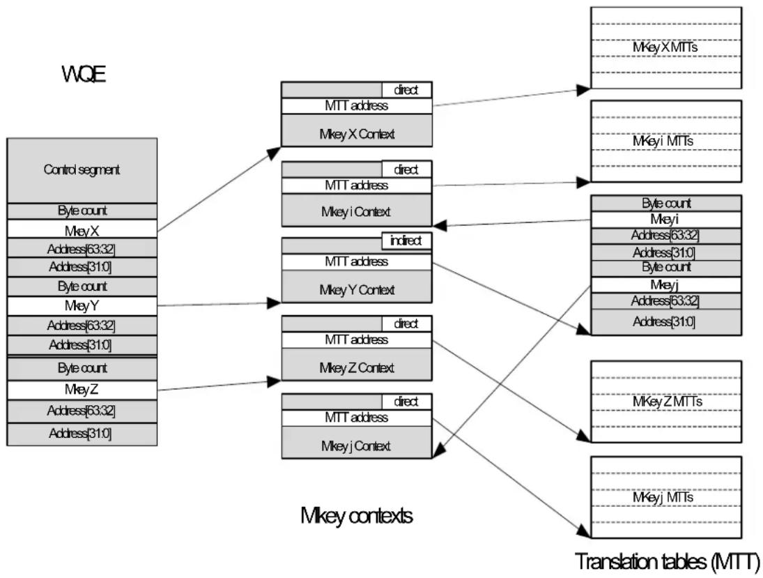
flowchart
graph TD
    A["Control segment"] --> B["MIkey contexts"]
    A --> C["MKey X MTTs"]
    A --> D["MKey i MTTs"]
    A --> E["MIkey MTTs"]
    B --> F["MTT address"]
    B --> G["Mkey X Context"]
    C --> H["MTT address"]
    C --> I["Mkey i Context"]
    D --> J["MTT address"]
    D --> K["Mkey Y Context"]
    E --> L["MTT address"]
    E --> M["Mkey Z Context"]
    F --> N["direct"]
    G --> O["direct"]
    H --> P["indirect"]
    I --> Q["indirect"]
    J --> R["direct"]
    K --> S["direct"]
    L --> T["MTT address"]
    L --> U["Mkey Z Context"]
    M --> V["MTT address"]
    M --> W["Mkey j Context"]
    N --> X["MKey X MTTs"]
    O --> Y["MKey i MTTs"]
    P --> Z["Byte count"]
    Q --> AA["Byte count"]
    R --> AB["Address[63:32"]]
    S --> AC["Address[31:0"]]
    T --> AD["Address[63:32"]]
    U --> AE["Address[31:0"]]
    V --> AF["MKey Z MTTs"]
    W --> AG["MKey j MTTs"]
The indirection capability enables a host to specify a scatter/gather list of unconstrained size and length memory buffers as the target of RDMA operations using a very fast lightweight memory registration process. Nesting of indirect translations is limited to the number of iterations that is globally configured in the device. If the number of translation indirections exceeds the configured limit, the address translation operation terminates with an error.
Indirect MKeys are programmed via the UMR Work Request, for details please see “User-Mode Memory Registration (UMR)” on page 158.
6.2 Zero-Based Virtual Address Regions and Windows
Zero-based virtual address regions are regions that start with virtual address zero. This property of the region is specified in the MKey context. Memory Windows cannot be bound onto zero-based regions.
The start of a zero-based memory region does not need to be aligned with the first page of the region (see Figure 10). The offset (in bytes) of the region's first address is specified in the MKey context.
Figure 10 illustrates an example of a zero-based memory region of 8Kbyte starting at offset of 0.5Kbyte from the beginning of first aligned page.
Figure 10: Zero Based Region/Window
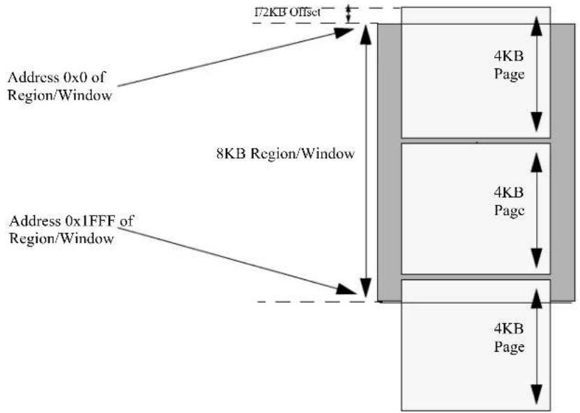
6.3 Reserved LKey
The HCA supports the use of a reserved LKey. When accessing memory using the reserved LKey, one-to-one mapping between virtual and physical addresses is done. The use of this key is qualified by the rlky bit in the RQ/SQ contexts. The LKey is programmed by the Level 0 privilege agent (for example VMM) at device initialization. The value of the reserved LKey is retrieved from the channel adapter by the QUERY_SPECIAL_CONTEXTS command executed by a Level 1 privilege agent.
6.4 Address Translation Control Structures
6.4.1 MKey Context
The MKey context is configured by the host software executing CREATE_MKEY command (see "CREATE_MKEY - Create MKey Entry" on page 228). Table 9, "MKey Context Format" shows format of the MKey context argument of this command while operating in enhanced mode.
Table 9 - MKey Context Format
| 31 | 30 | 29 | 28 | 27 | 2 | 6 | 25 | 24 | 23 | 22 | 21 | 20 | 19 | 18 | 17 | 16 | 15 | 14 | 13 | 12 | 11 | 10 | 9 | 8 | 7 | 6 | 5 | 4 | 3 | 2 | 1 | 0 | Offset |
| free | umr_en | rw | rr | w | lr | acces_s mode | 00h | ||||||||||||||||||||||||||
| qpn | mkey[7:0] | 04h | |||||||||||||||||||||||||||||||
| 08h | |||||||||||||||||||||||||||||||||
Table 9 - MKey Context Format
| 31 | 30 | 29 | 28 | 27 | 2 | 6 | 25 | 24 | 23 | 22 | 21 | 20 | 19 | 18 | 17 | 16 | 15 | 14 | 13 | 12 | 11 | 10 | 9 | 8 | 7 | 6 | 5 | 4 | 3 | 2 | 1 | 0 | Offset |
| length64 | pd | 0Ch | |||||||||||||||||||||||||||||||
| start_addr | 10-14h | ||||||||||||||||||||||||||||||||
| len | 18-1Ch | ||||||||||||||||||||||||||||||||
| 20h | |||||||||||||||||||||||||||||||||
| 24h | |||||||||||||||||||||||||||||||||
| 28h | |||||||||||||||||||||||||||||||||
| Ch | |||||||||||||||||||||||||||||||||
| 30h | |||||||||||||||||||||||||||||||||
| 34h | |||||||||||||||||||||||||||||||||
| translations_octword_size | 38h | ||||||||||||||||||||||||||||||||
| log_entity_size | 3Ch | ||||||||||||||||||||||||||||||||
The fields of the MKey context is shown in Table 10.
Table 10 - MKey Context Fields
| Offset Bits Name | Description | Access | |
| 00h | 30 | free | 0 - memory key is in use. It can be used for address translation1 - memory key is free. Cannot be used for address translation |
| 15 umr en Enable umr operation on this MKey | |||
| 13 rw If set, remote write is enabled | |||
| 12 rr If set, remote read is enabled | |||
| 11 | lw | If set, local write is enabled | |
| 10 | lr | If set, local read is enabled. Must be set for all MKeys | |
| 9:8 | access mode | 0x0: PA - (VA=PA, no translation needed) if set, no virtual to physical address translation is performed for this MKey. Not valid for, block mode MKey, replicated MTT MKey0x1: MTT - (PA is needed)0x2: KLMs - (Indirect access) | |
Table 10 - MKey Context Fields
| Offset | Bits | Name | Description | Access |
| 04h 31:8 | qpn must be 0xffff. | |||
| 7:0 mkey[7:0] | Variant part of MKey specified by this MKey context | |||
| 0Ch | 31 | length64 | Enable registering 2^64 bytes per region | |
| 23:0 pd | Protection domain | |||
| 10h-14h | 64 start | addr | Start Address - Virtual address where this region/window starts | |
| 18h-1Ch | 64 | len | Region length. Reserved when length64 bit is set (in which case the region length is 2^64B). | |
| 34h 31:0 | translations_octword_size | Size (in units of 16B) required for this MKey's physical buffer list or SGEsaccess_mode: MTT - each translation is 8Baccess_mode: KLM - each SGE is 16Baccess_mode: PA - reservedMust be a multiple of 4 | ||
| 38h 4:0 | log_cnti-ty_size | When access_mode==MTT: log2 of Page size in bytes granularity.otherwise: reserved.Must be >=12 | ||
The following table describes the usage of umr bit in the MKC.
The MTT Entry contains the physical tag. An entry of the Memory Translation is shown in Table 11.
Table 11 - Memory Translation Table (MTT) Entry Layout
| 31 | 30 | 29 | 28 | 27 | 26 | 25 | 24 | 23 | 22 | 21 | 20 | 19 | 18 | 17 | 16 | 15 | 14 | 13 | 12 | 11 | 10 | 9 | 8 | 7 | 6 | 5 | 4 | 3 | 2 | 1 | 0 | Offset |
| ptag[63:32] | 00h | |||||||||||||||||||||||||||||||
| ptag[31:8] | wr en | rd en | 04h | |||||||||||||||||||||||||||||
Table 12 - Memory Translation Table (MTT) Entry
| Offset | Bits | Name | Description | Access |
| 00h | 31:0 | ptag[63:32] | High-order bits of physical tag. The size of the field depends on the page size of the region. | |
| 04h 31:8 | ptag[31:8] | |||
| 1 | wr_en | Write enable. | ||
| 0 | rd_en | Read enable. | ||
6.5 Memory Key Configuration (Creation)
Memory Key object is initialized (created) by the privileged SW entity using the CREATE_M-KEY command.
7 Software Interface
This chapter describes all the interfaces between the driver software and the device hardware, including specific control flows of the device. It contains the following sections:
• Section 7.1, “ISSI - Interface Step Sequence ID,” on page 62
• Section 7.2, “User Access Region (UAR),” on page 63
• Section 7.3, “NIC_Vport Context - NIC Virtual Port Context,” on page 66
• Section 7.4, “Work Queues,” on page 69
• Section 7.5, “Transport Interface Receive (TIR),” on page 84
• Section 7.6, “Transport Interface Send (TIS),” on page 89
• Section 7.7, “Receive Queue (RQ),” on page 90
• Section 7.9, “Send Queue (SQ),” on page 99
• Section 7.10, “Receive Memory Pool (RMP),” on page 104
• Section 7.11, “Flow Table,” on page 107
• Section 7.12, “Completion Queues,” on page 114
• Section 7.13, “Events and Interrupts,” on page 132
• Section 7.14, “Command Interface,” on page 144
7.1 ISSI - Interface Step Sequence ID
ISSI of this PRM revision is 1.
This parameter defines the step sequence ID of the interface between SW and the device. It is incremented by steps of 1.
ISSI is used to enable deprecating/modifying features, command interfaces as well as software, maintaining compatibility within the same ISSI value.
SW implementing this revision of the PRM should remember the ISSI of the PRM. In addition, during initialization flow (see Section 11.2, "HCA Driver Start-up," on page 366), SW must perform a query of the supported ISSIs using QUERY_ISSI command (see Section 12.3.10, "QUERY_ISSI," on page 216), and then set the actual_issi informing the device on which ISSI to run, using SET_ISSI command (see Section 12.3.11, "SET_ISSI," on page 218).
It is clear that SW cannot run with an ISSI which is not supported by the device, so the actual_issi which software should set for the device must be = min (sw issi, max supported_issi).
Note that if QUERY_ISSI command returns with BAD_OPCODE, this indicates that the supported_issi is only 0, and there is no need to perform SET_ISSI.
7.1.1 ISSI History
This section describes the overall interface changes each time ISSI incremented.
7.1.1.1 ISSI = 1
- Added cqe_version to HCA_CAP (see Table 144, “HCA Capabilities Layout,” on page 196). SW must read this field to identify the cqe version.
7.2 User Access Region (UAR)
The isolated, protected and independent direct access to the HCA HW by multiple processes is implemented via User Access Region (UAR) mechanism.
The UAR is part of PCI address space that is mapped for direct access to the HCA from the CPU. UAR is comprised of multiple pages, each page containing registers that control the HCA operation. UAR mechanism is used to post execution or control requests to the HCA. It is used by the HCA to enforce protection and isolation between different processes.
The cross-process isolation and protection is implemented through four key mechanisms:
- Host SW maps different UAR pages to different consumers, hereby enforcing isolation between different consumers to access the same page in the HCA control space.
- Each Control Object can be accessed (controlled) through a UAR page.
- HCA driver associates a UAR page with a control object while initializing (“opening”) the object.
- Prior to executing control operation on the object, HCA validates that the UAR page used to post the command matches the one specified in the contexts of that object.
Operation is passed to the HCA by posting WQE to respective Work WQ, updating Doorbell Record (where applicable) and writing to respective Doorbell Register in the UAR page associated with that Work WQ. Writing to Doorbell Register of the HCA is further referred to as ringing DoorBell. The DoorBell register in the UAR is the first 2 DWORDS of the blue-flame buffer.
7.2.1 UAR Sections
The UAR is implemented as a single BAR register per each function that contains multiple pages; page size should match the CPU (system) page size, and should be configured at device initialization. Figure 11 illustrates the structure of the UAR BAR.
Figure 11: HCA BAR Structure
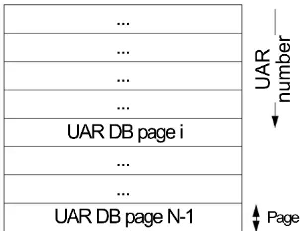
7.2.2 UAR Page Format
Table 13 shows the layout of UAR page.
Table 13 - UAR Page Format
| 31 | 30 | 29 | 28 | 27 | 26 | 25 | 24 | 23 | 22 | 21 | 20 | 19 | 18 | 17 | 16 | 15 | 14 | 13 | 12 | 11 | 10 | 9 | 8 | 7 | 6 | 5 | 4 | 3 | 2 | 1 | 0 | Offset | register | ||||||||
| 00h-1Ch | |||||||||||||||||||||||||||||||||||||||||
| 20h | CQ | ||||||||||||||||||||||||||||||||||||||||
| 24h | 28h-3Ch | ||||||||||||||||||||||||||||||||||||||||
| 40h | EQ | ||||||||||||||||||||||||||||||||||||||||
| 44h | |||||||||||||||||||||||||||||||||||||||||
| 48h | |||||||||||||||||||||||||||||||||||||||||
| 04Ch-7FCh | |||||||||||||||||||||||||||||||||||||||||
| DB_BlueFlame_Buffer0_even | 800-0FCh | Blue Flame Reg0 | |||||||||||||||||||||||||||||||||||||||
| DB_BlueFlame_Buffer0_odd | 900-9FCh | Blue Flame Reg1 | |||||||||||||||||||||||||||||||||||||||
| DB_BlueFlame_Buffer1_even | A00-AFCh | ||||||||||||||||||||||||||||||||||||||||
| DB_BlueFlame_Buffer1_odd | B00-BFCh | ||||||||||||||||||||||||||||||||||||||||
Table 14 - CQ DoorBell Register Field Descriptions
| Bits Name Description | ||
| 2 | cmdsn | Command Sequence Number. This value should be ‘0 for the first DoorBell rung, and should be increment on each first DoorBell rung after a completion event. That is, cmdsn = (num_of_completion_event_delivered + 1)% 4. |
| 1 | cmd | 0 - Request notification for next Solicited or Unsolicited completion event. cq_ci field should specify the CQ Consumer Counter at the time of the DoorBell ring.1 - Request notification for next Solicited completion event. cq_ci field should specify the CQ Consumer Counter at the time of the DoorBell ring. |
Table 14 - CQ DoorBell Register Field Descriptions
| Bits Name Description | ||
| 24 cqn | CQ number | accessed |
| 24 cq_ci | Consumer | Counter of last-polled completion |
Send DoorBells are rung in blue flame registers by writing the first 8 bytes of the WQE (that contains post counter, DS and SQ number) to offset 0 of the blue flame register (See Table 25, "General - Ctrl Segment Format"). This post counter points to the beginning of the WQE to be executed. Note that this is different than the counter in the DB record which points to the next empty WQEBB. Send DBs of a SQ can be rung on specific Blue Flame registers and cannot be interleaved on multiple Blue Flame registers.
Completion WQ DoorBells are rung in CQ register by writing CQ number, command, command sequence and CQ Consumer Index to respective fields. For best performance, this should be performed as a single 64-bit write operation.
Event WQ DoorBells are rung on the EQ register by writing the EQ number and the EQ consumer index. Writing to the first register will Arm the EQ. The second one will just update the consumer index without arming. When the EQ is armed, next event posted to the EQ will generate HW interrupt associated with this Event WQ. For details, refer to Table 93, “Event Queue Context Layout” on page 139
A recommended usage model, for getting interrupt whenever there is EQE in EQ is as follows: When arming the EQ at the first time, Consumer-index should be 0. When SW depletes the EQ from events, if it pop X events from the EQ, consumer-index should be incremental by X.
7.2.2.1 Blue Flame
BlueFlame is a low-latency mechanism that can be used to post latency-critical Send WQEs to the device. When BlueFlame is used, WQEs get written directly to a PCI BAR of the device (in addition to memory) so that the device may handle them without having to access memory, thus shortening the execution latency. For best performance, it is recommended to use BlueFlame when the HCA is lightly loaded. For high-bandwidth scenarios, it is recommended to use regular posting (without BlueFlame).
BlueFlame properties can be retrieved by querying the HCA_CAP. The BlueFlame is described through the following fields: bf, log_bf_reg_size, log_max_bf_regs_per_page and log_max_b-f_pages.
The BlueFlame section contains equally-sized BlueFlame registers. Each such register contains a pair of equally-sized BlueFlame buffers. Each register (2 buffers) size is 2^_bf_reg_size bytes. The layout of a BlueFlame page is shown in Table 13.
A BlueFlame buffer is used to post a Send Work Request. The WQE should be written directly to one of the BlueFlame register buffers as explained in “Posting a Work Request to Work Queue” on page 74. If WQE size is bigger than BlueFlame buffer size, then the WQE cannot be posted using BlueFlame. The two buffers in the BlueFlame register must be used alternately; in other words, BlueFlame_Bufferi_even should be used for each even posting to BlueFlame register i, and BlueFlame_Bufferi_odd should be used for each odd posting to the same register. Blue flame registers 2 and 3 are used for “fast path” posting.
When posted to a BlueFlame buffer, a WQE should be formatted as described in “Send WQE Format” on page 75.
BlueFlame register buffer must be written in chunks of DWORDs (aligned on 4 bytes) or multiple DWORDs. It may, though it is not recommended, be written out-of-order with respect to the offset of the posted writes. Different BlueFlame registers can be accessed by software simultaneously and independently. This way a single BlueFlame page can be used by multiple threads (permitted to access the same page) without locking. However, if software wishes to write different WQEs to the same BlueFlame register, it must use semaphores in order to avoid interleaving between the WQEs.
Blue Flame register should be written using Write Combining, generating bursts of one (or more) cache lines. If the WQE size is smaller than (a multiple of) a cache line, the WQE written to the Blue Flame buffer should be padded up to the closest cache line boundary. The HW uses the DS field of the WQE to determine the boundary of the WQE written to the Blue Flame buffer. Note that the WQE must be posted to the Work WQ without padding.
For regular (not BlueFlame) DoorBells, it is recommended not to use Write combining. The Doorbell and the Blue Flame registers are on the same UAR page. Therefore, it is recommended to map this UAR page twice. Once as write combining (for Blue Flame) and once as non Write Combining for regular DoorBells. For WQEs with DS=1, blue flame is not supported. DS=1 is the case for NOP or zero length send operations. The driver can either use regular posting (no blue flame) for this case or it can pad the WQE with extra zero length data segment as explained in “Send Data Segments” on page 81, thus extending DS to 2, which enables submission of blue flame on the WQE.
7.2.2.2 Sharing UARs
SQ/RQ and CQ DoorBells require 64-bit writes. For best performance, it is recommended to execute the SQ/RQ/CQ DoorBell as a single 64-bit write operation. For platforms that do not support 64 bit writes, it is possible to issue the 64 bits DoorBells through two consecutive writes, each write 32 bits, as described below:
- The order of writing each of the DWORDs is from lower to upper addresses.
- No other DoorBell can be rung (or even start ringing) in the midst of an on-going write of a DoorBell over a given UAR page.
The last rule implies that in a multi-threaded environment, the access to a UAR page (which can be accessible by all threads in the process) must be synchronized (for example, using a semaphore) unless an atomic write of 64 bits in a single bus operation is guaranteed. Such a synchronization is not required for when ringing DoorBells on different UAR pages.
7.3 NIC\_Vport Context - NIC Virtual Port Context
For more details on NIC_Vport context see Section 3.1.2, "Vport Context," on page 109.
Table 15 presents Vport context structure.
Table 15 - NIC_Vport Context Layout
| 31 | 30 | 29 | 28 | 27 | 26 | 25 | 24 | 23 | 22 | 21 | 20 | 19 | 18 | 17 | 16 | 15 | 14 | 13 | 12 | 11 | 10 | 9 | 8 | 7 | 6 | 5 | 4 | 3 | 2 | 1 | 0 | Offset |
| min_wqe_inline_-mode | 00h 04 | |||||||||||||||||||||||||||||||
Table 15 - NIC_Vport Context Layout
| 31 | 30 | 29 | 28 | 27 | 26 | 25 | 24 | 23 | 22 | 21 | 20 | 19 | 18 | 17 | 16 | 15 | 14 | 13 | 12 | 11 | 10 | 9 | 8 | 7 | 6 | 5 | 4 | 3 | 2 | 1 | 0 | Offset |
| 08h-20h | ||||||||||||||||||||||||||||||||
| mtu | 24h | |||||||||||||||||||||||||||||||
| 40h-5Ch | ||||||||||||||||||||||||||||||||
| 68h | ||||||||||||||||||||||||||||||||
| 6Ch-ECh | ||||||||||||||||||||||||||||||||
| promise_uc | promise_all | allowed_list_type | allowed_list_size | F0h | ||||||||||||||||||||||||||||
| permanent_address( See Table 19, “MAC Address Layout,” on page 69) | F4h-F8h | |||||||||||||||||||||||||||||||
| FCh | ||||||||||||||||||||||||||||||||
| current_uc_mac_address[0]/current_mc_mac_address[0]/vlan[0] | 100h-104h | |||||||||||||||||||||||||||||||
| current_uc_mac_address[1]/current_mc_mac_address[1]/vlan[1] | 108h-10Ch | |||||||||||||||||||||||||||||||
| ... | 120h-... | |||||||||||||||||||||||||||||||
Table 16 - NIC_Vport Context Field Descriptions
| Offset | Bits | Name | Description | Access |
| 00h 26 | :24 min_wqe_in-line_mode | Sets the minimal allowed inline mode for NIC Vport SQs.Each SQ has inline mode that defines the minimal required inline headers in Eth Segment of the SQ's WQEs.Note: SQ.min_wqe_inline_mode must be >=Nic_vport.min_sq_wqe_inline_mode.For more details - See Section 7.4.4.1.2, "Eth Segment and Padding Segment," on page 76.Valid only when HCA_CAP.wqe_inline_mode ==1 | ||
| 24h | 15:0 | mtu | MTU size required for Vport.In query, 0 means MTU of Vport equal to external physical port. | |
Table 16 - NIC_Vport Context Field Descriptions
| Offset | Bits | Name | Description | Access |
| F0h | 31 | promisc_uc | When set, request to allow any unicast address on vlan list. | |
| 30 | promisc_mc | When set, request to allow any multicast address on vlan list. | ||
| 29 | promisc_all When set, request to allow all traffic. | |||
| 26:24 allowed_list_type | Determine the allowed list type0: current_uc_mac_address1: current_mc_mac_address2: vlan_list | |||
| 11:0 allowed_list_size | Size of the addresses list.The list type is defined by allowed_list_type.For allowed_list_type==current_uc_mac_address, allowed_list_size must be <=HCA_CAP.log_max_current_uc_list.For allowed_list_type==current_mc_mac_address, allowed_list_size must be <=HCA_CAP.log_max_current_mc_listFor allowed_list_type==current_uc_mac_address, allowed_list_size must be <=HCA_CAP.log_max_vlan_list | |||
| F4h-F8h | 64 per-ment_address(See Table 19, "MAC Address Layout," on page 69) | Permanent address.MAC address format. See Table 19, "MAC Address Layout," on page 69. | ||
| 100h-... | 64 cur-rent_uc_mac_address[...]/current_mc_mac_address[...]/vlan[...] | List of the allowed addresses on a nic_vport.The size of the list is determined by allowed_list_size, and the type of the list is determined by allowed_list_type.For the format of uc_mac_address/mc_mac_address: See Table 19, "MAC Address Layout," on page 69.For the format of vlan, See Table 17, "Vlan Layout," on page 68. | ||
Table 17 - Vlan Layout
| 31 | 30 | 29 | 28 | 27 | 26 | 25 | 24 | 23 | 22 | 21 | 20 | 19 | 18 | 17 | 16 | 15 | 14 | 13 | 12 | 11 | 10 | 9 | 8 | 7 | 6 | 5 | 4 | 3 | 2 | 1 | 0 | Offset |
| vlan | 00h | |||||||||||||||||||||||||||||||
| 04h | ||||||||||||||||||||||||||||||||
Table 18 - Vlan Field Descriptions
| Offset | Bits | Name | Description | Access |
| 00h | 11:0 | vlan | vlan |
Table 19 - MAC Address Layout
| 31 | 30 | 29 | 28 | 27 | 26 | 25 | 24 | 23 | 22 | 21 | 20 | 19 | 18 | 17 | 16 | 15 | 14 | 13 | 12 | 11 | 10 | 9 | 8 | 7 | 6 | 5 | 4 | 3 | 2 | 1 | 0 | Offset |
| mac_addr[47:32] | 00h | |||||||||||||||||||||||||||||||
| mac_addr[31:0] | 04h | |||||||||||||||||||||||||||||||
Table 20 - MAC Address Field Descriptions
| Offset | Bits | Name | Description | Access |
| 00h | 15:0 mac_addr[47:32] | Upper bits of mac address. | ||
| 04h | 31:0 mac_addr[31:0] | Lower bits of mac address. | ||
7.4 Work Queues
Work Request is posted to the HCA by writing a list of one or more Work Queue Elements (WQE) to the WQ and ringing the DoorBell, notifying the HCA that request has been posted.
This section describes the structure and management of WQs and the WQE format.
HCA WQ is an object containing the following entities:
- SQ/RQ Context - Contains control information required by the device to execute I/O operations on that Context. These contexts are configured by SW at creation time.
-
Work Queue Buffer - A virtually-contiguous memory buffer allocated when creating the SQ/RQ:
-
Send Queue - A virtually-contiguous circular buffer accessible by user-level software and used to post send requests. Maximum supported SQ size is retrieved by the QUERY_HCA_CAP command (log_max_qp_sz), see Table 144, "HCA Capabilities Layout," on page 196.
-
Receive Queue - A virtually-contiguous circular buffer accessible by user-level software and used to post receive requests. Maximum supported RQ size is retrieved by the QUERY_HCA_CAP command (log_max_qp_sz), see Table 144, "HCA Capabilities Layout," on page 196.
-
DoorBell Record - A structure containing information of most recently-posted Work Request.
7.4.1 Work Queues Structure and Access
The device WQ is a virtually-contiguous memory buffer used by SW to post I/O requests (WQEs) for HCA execution. A WQ is comprised of WQE Basic Blocks (WQEBBs); WQE size is modulo of WQEBB size.
Each WQ buffer contains the Send WQ and Receive WQ adjacently. The RQ resides in the beginning of the buffer; Figure 12 illustrates the structure of Work Queue Buffer.
The buffer must be aligned on WQEBB/Stride (the larger of the two); RQ must be aligned to 64B even if RQ stride is smaller than 64B. RQ can be of zero size. The offset of WQE in the first page (page_offset) is delivered to the device while configuring the SQ/RQ.
Figure 12: Work Queue Buffer Structure
SQ and RQ Shared Receive Queue
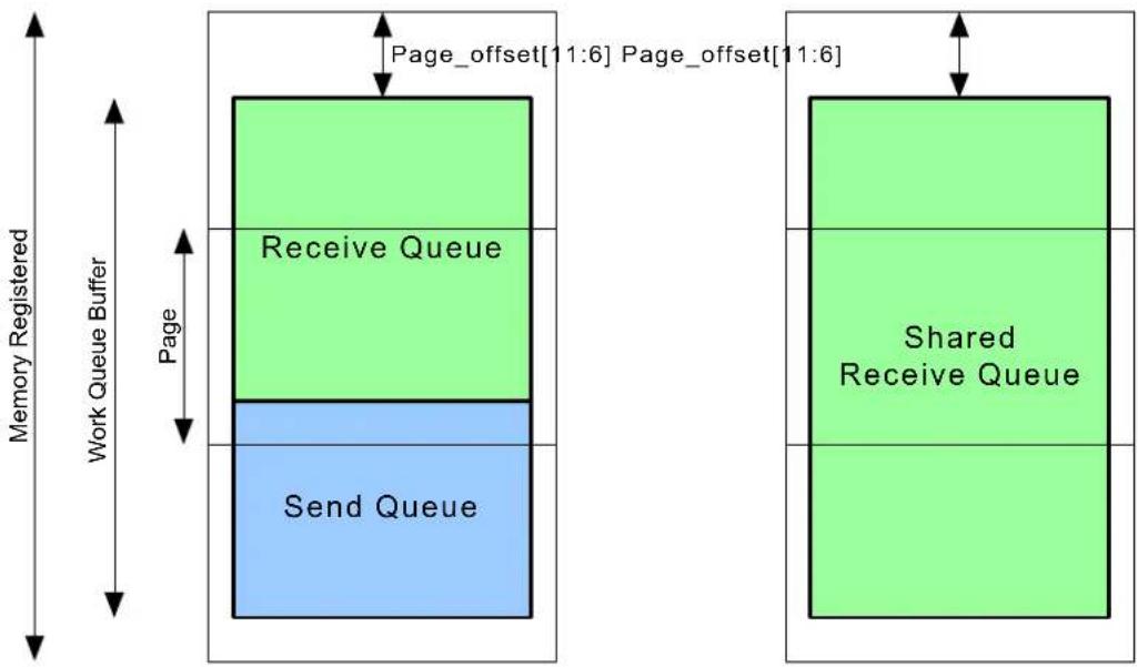
flowchart
graph TD
    A["Receive Queue"] -->|Page_offset["11:6"]| B["Shared Receive Queue"]
    C["Send Queue"] -->|Page| A
    D["Memory Registered"] --> A
    D --> C
    style A fill:#90EE90,stroke:#333
    style B fill:#90EE90,stroke:#333
    style C fill:#90EE90,stroke:#333
    style D fill:#90EE90,stroke:#333
7.4.1.1 Send Queue
The size of Send WQ is specified in units of Work Queue Basic Blocks (WQEBBs). The size of a WQEBB is 64 bytes. The size (or depth) of the SQ is a power-of-two number of WQEBBs, and therefore the queue itself is a power-of-two size (in bytes). The maximum SQ size in WQEs can be retrieved through the QUERY_HCA_CAP command ( 2^log_max_qp_sz ).
SQ is organized as a circular buffer containing Send WQEs. Each posted WQE can occupy one or more basic blocks. This enables using large WQEs without wasting memory on huge WQs.
Note that the value of _sq_size does not necessarily equal the number of WQEs that can be posted to the SQ. Rather, it reflects the maximum number in case where the size of each posted WQE is smaller than or equal to WQEBB. Thus, the number of WQEs that can be posted may vary depending on the actual posted WQE sizes. The maximum WQE size can be retrieved by QUERY_HCA_CAP command (and _wqe_sz_sq ). Figure 13 illustrates the Send WQ with three WQEs of different sizes posted.
Figure 13: Send Work Queue With 3 WQEs Posted
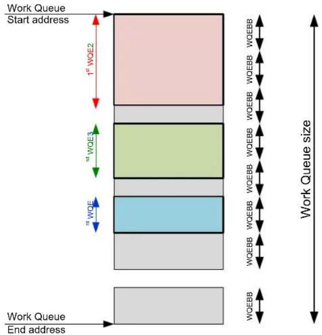
SQ WQEs are identified by sq_wqebb_counter, which starts at zero and advances with each WQE post by number of WQEBBs this WQE occupies and is stored in Send Doorbell Record. sq_wqebb_counter wraps around 0xFFFF.
WQE can wrap around the Send WQ if it starts close to the edge of the WQ and does not fit into the space left. This phenomena is illustrated in Figure 14.
Figure 14: WQE Wrap-around in WQ Buffer
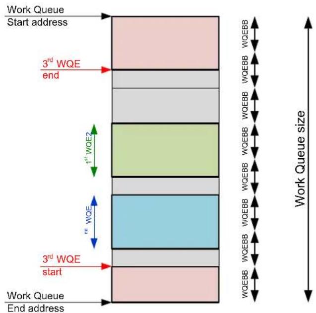
7.4.1.2 Receive Queue
RQ is organized as a circular buffer containing Receive WQEs. Receive WQEs are placed at fixed stride in the Receive WQ buffer and are executed in the order of their appearance in the buffer. The stride is specified in the WQ in a multiple of 16-byte chunks; the number of these chunks must be a power of two. The maximum RQ size in strides can be retrieved through the QUERY_HCA_CAP command ( 2^log_max_qp_sz ). Maximum WQE size supported is retrieved by QUERY_HCA_CAP command. Can be 512B or smaller.
Each 16-byte chunk of Receive WQE contains a single scatter pointer and byte count. If WQ stride size is larger than the actual WQE, the scatter pointers list can be terminated with scatter pointer specifying a zero value in the byte_count field and L_Key = 0x00000100. This scatter pointer is interpreted by HW as end of the scatter list and is referred thereafter as Null scatter pointer.
Table 21 - Receive Queue - Scatter Entry Format
| 31 | 30 | 29 | 28 | 27 | 26 | 25 | 24 | 23 | 22 | 21 | 20 | 19 | 18 | 17 | 16 | 15 | 14 | 13 | 12 | 11 | 10 | 9 | 8 | 7 | 6 | 5 | 4 | 3 | 2 | 1 | 0 | Offset | ||
| Byte Count | 00h | Pointer | ||||||||||||||||||||||||||||||||
| L_key | 04h | |||||||||||||||||||||||||||||||||
| Local address[63:32] | 08h | |||||||||||||||||||||||||||||||||
| Local address[31:0] | 0Ch | |||||||||||||||||||||||||||||||||
Table 22 - Receive Queue - Signature Entry Format
| 31 | 30 | 29 | 28 | 27 | 26 | 25 | 24 | 23 | 22 | 21 | 20 | 19 | 18 | 17 | 16 | 15 | 14 | 13 | 12 | 11 | 10 | 9 | 8 | 7 | 6 | 5 | 4 | 3 | 2 | 1 | 0 | Offset | |
| 00h | signature | ||||||||||||||||||||||||||||||||
| signature | 04h | ||||||||||||||||||||||||||||||||
| 08h 0Ch | |||||||||||||||||||||||||||||||||
| Ch | |||||||||||||||||||||||||||||||||
Table 23 - Receive Queue - Signature Entry Fields
| Offset Bits Field | Description | |
| 04h | 31:25 | signature |
Figure 15 illustrates the Receive WQ with three WQEs posted.
Figure 15: Receive Work Queue with 3 WQEs Posted
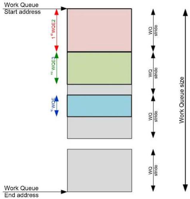
RQ WQEs are identified by the rq_wqe_counter, which starts at 0 and advanced by 1 each time a WQE is posted to the RQ and stored to Receive Doorbell Record. rq_wqe_counter wraps around 0xFFFF.
7.4.2 Doorbell Record
Doorbell records are located in physical memory. The address of DoorBell record is passed to the HW at RQ/SQ creation. The receive and send DoorBell record are consecutive in memory. DB records are aligned on a 4 byte boundary. The DoorBell record denotes the counter (sq_wqebb_counter for SQ and wqe_counter for receive and shared RQs), which reflects the number of WQEs posted to this queue since its creation. Specifically, it points to the first empty WQEBB (SQ) or WQE stride (RQ). The counter wraps around at 0xFFFF for all other queues. Doorbell Record format is shown in Table 24.
Table 24 - Doorbell Record format
| 31 | 30 | 29 | 28 | 27 | 26 | 25 | 24 | 23 | 22 | 21 | 20 | 19 | 18 | 17 | 16 | 15 | 14 | 13 | 12 | 11 | 10 | 9 | 8 | 7 | 6 | 5 | 4 | 3 | 2 | 1 | 0 | Offset | |
| counter | 00 | Receive send | |||||||||||||||||||||||||||||||
| counter | 04 | ||||||||||||||||||||||||||||||||
Doorbell record should be initiated to 0 at the creation.
7.4.3 WQE Ownership
Hardware reads and executes WQEs from WQs asynchronously to SW posting new WQEs; each WQE is executed only once, and completion is optionally reported to the CQ associated with WQ. The WQE can be executed by the HCA only if its ownership has been passed to HW.
The WQE ownership is passed to HW by updating the Doorbell Record, posting there respective WQE counter (sq_wqebb_counter and rq_wqe_counter for send and receive DoorBell records respectively).
Once WQE ownership has been passed to the HCA, HW can execute the WQE. Neither WQE nor data buffers associated with this WQE can be modified by SW until WQE ownership has been returned back to the SW. Altering WQE or associated data buffer can have lethal consequences to that WQ. It is guaranteed, however, that operation of other queues will not be affected.
After a WQE has been executed, its ownership is passed to SW by posting CQE to respective CQ.
7.4.3.1 Posting a Work Request to Work Queue
In order to post Work Request to WQ, software should execute the following steps:
- Write WQE to the WQE buffer sequentially to previously-posted WQE (on WQEBB granularity).
- Update Doorbell Record associated with that queue by writing their sq_wqebb_counter or wqe_counter for send and RQ respectively
- For send request ring DoorBell by writing to the Doorbell Register field in the UAR associated with that queue. For performance-critical send WQEs DoorBell can be rang by using the BlueFlame mechanism (see "Blue Flame" on page 65).
For send requests the third step (DoorBell) guarantees that send WQE will be executed. However, HW may execute WQE after the second step has been completed. Ringing DoorBell for WQE that has already been executed makes no harm - such a DoorBell is ignored by the HW.
Software can post a list of WQEs together by repeating step 1 for all WQEs, then updating the DoorBell record (step 2) once and ringing one DoorBell (step 3). The DoorBell record wqeb-b_counter should count all WQEs posted and the wqe_index in the DoorBell should point to the first wqebb of the last WQE posted.
For receive requests, updating DoorBell record passes receive WQE ownership to HW and receive operation will be executed upon arrival of respective send packet.
7.4.3.2 Posting Work Request on Shared Receive Queue
While posting Work Request to the SRQ, software should take the following steps:
- Locate a slot in WQ to be used for the WQE that will be posted after the current one being posted and write its pointer to next/control segment of the newly-created WQE. Since next/control segment of the WQE contains address of next WQE, the location of next WQE to be posted is determined while posting a current WQE.
- Write WQE (the scatter list, concluding with Null scatter pointer if required) to the slot located in step (1) of previously-posted WQE.
- Update Doorbell Record associated with that SRQ writing there rq_wqe_counter.
The third step (DoorBell record update) passes receive WQE ownership to HW and receive operation will be executed upon arrival of respective send request.
7.4.4 Work Request (WQE) Formats
The maximum length of a Work Request (WQE) reported in HCA_CAP.max_wqe_sz_rq and max_wqe_sz_sq, and is specified in octowords (16-byte chunks). WQEs must be aligned on WQEBB/Stride.
7.4.4.1 Send WQE Format
Send WQEs are built from the segments that are listed below. Segment size is a multiple of 16 bytes. Each WQE contains a subset of these segments, depending on the requested operation, as shown in Table 41, “WQE Construction Summary”. For each transport service and operation, segments must be in accordance with Table 41, “WQE Construction Summary” and with the order shown in the list below:
- Ctrl Segment - The segment contains some control information for the current WQE. This segment is described in Section 7.4.4.1.1, “Ctrl Segment,” on page 75.
- Eth Segment - Contains packet headers and information for stateless L2, L3, L4 offloading. This segment is described in Section 9.3.4.1.5, “Eth Segment and Padding Segment,” on page 140.
- Memory Management Segment - Contains the parameters required for a Memory Management WQEs (UMR). This segment is described in Section 7.4.4.1.3, “User-mode Memory Registration (UMR) WQE Format,” on page 78 and on.
- Data Segments - Contain pointers and a byte count for the scatter/gather list. They can optionally contain data, which will save a memory read access for gather Work Requests. The WQE can contain single or multiple memory pointer segments, single or multiple in-line Data segments, or any combination of these.
7.4.4.1.1 Ctrl Segment
This segment contains control information of the WQE. The interpretation and validity of some fields depends on the transport service deployed on the SQ processing the WQE.
Format of the general control segment is shown in Table 25.
Table 25 - General - Ctrl Segment Format
| 31 | 30 | 29 | 28 | 27 | 26 | 25 | 24 | 23 | 22 | 21 | 20 | 19 | 18 | 17 | 16 | 15 | 14 | 13 | 12 | 11 | 10 | 9 | 8 | 7 | 6 | 5 | 4 | 3 | 2 | 1 | 0 | Offset | ||||||
| WQE Index OPCODE | 00h | |||||||||||||||||||||||||||||||||||||
| SQ number DS | 04h | |||||||||||||||||||||||||||||||||||||
| signature | 08h | |||||||||||||||||||||||||||||||||||||
| umr_mkey | 0Ch | |||||||||||||||||||||||||||||||||||||
Table 26 specifies fields in the control segment.
Table 26 - General Ctrl Segment Field
| Offset Bits Name | Description | |
| 00h 31:24 reserved | ||
| WQE Index | ||
| 00h | 7:0 | OPCODE |
| 04h | 31:8 | SQ number |
| 5:0 | DS | |
| 08h | 31:24 | signature |
| 7:5 FM | Fence Mode000 - No Fence001 - Initiator Small Fence.Wait as long as there are WQEs that are currently locally in execution (doing gather / memop etc.) | |
| 3:2 CE | Completion and Event mode00 - Generate CQE only on WQE completion with error.01 - Generate CQE only on first WQE completion with error (i.e if CQE on previous WQE completed in error, no CQE will be generated)10 - Generate CQE on WQE completion (good or bad)11 - Generate CQE and EQE (local Solicited event). | |
| 1 | SE | |
| 0Ch | 31:0 i | invalidation_key/ umr_mkey |
7.4.4.1.2 Eth Segment and Padding Segment
This segment contains stateless offloading control and inlined Ethernet packet headers. This segment is used for Ethernet SQs. When the Eth header is used on Ethernet SQs, it is used as is.
The Eth segment contains the headers of the packets inlined within the segment. Headers that are inlined should be excluded from the data segments that follow the Eth segment. The begging of the inline header depends on the protocol offloaded as follows:
- For standard Ethernet - the packet inlined headers start from the Ethernet header.
The minimal required inline headers depend on HCA_CAP.wqe_inline_mode. See Table 146, "Per Protocol Networking Offload Capabilities Layout," on page 202.
The format of the Eth segment is shown in Table 27.
Table 27 - Eth Segment Format
| 31 | 30 | 29 | 28 | 27 | 26 | 25 | 24 | 23 | 22 | 21 | 20 | 19 | 18 | 17 | 16 | 15 | 14 | 13 | 12 | 11 | 10 | 9 | 8 | 7 | 6 | 5 | 4 | 3 | 2 | 1 | 0 | Offset | seg | ||||||
| 00h | Eh | ||||||||||||||||||||||||||||||||||||||
| 14cs | 13cs | mss | 04h 08h | ||||||||||||||||||||||||||||||||||||
| 0Ch | |||||||||||||||||||||||||||||||||||||||
| inline_header_size inline headers | 10h | ||||||||||||||||||||||||||||||||||||||
| inline headers cont'd | 14h | ||||||||||||||||||||||||||||||||||||||
| ... | 18h | ||||||||||||||||||||||||||||||||||||||
| ... | 1Ch | ||||||||||||||||||||||||||||||||||||||
| ... | 1Ch | ||||||||||||||||||||||||||||||||||||||
Table 28 specifies fields in the Eth Segment.
Table 28 - Eth Segment Fields
| Offset Bits Name | Description | ||
| 04h | 31 | l4cs | When set - the device calculates checksum on the L4 header (TCP/UDP) that follows the IP header. (In case of tunneling, it is the one which follows the outer IP header)For non TCP/UDP packets, the device ignores this bit.When l4cs_inner is set must be disabled. |
| 30 | l3cs | When set - the device calculates checksum on the L3 header (IPv4). (In case of tunneling, it is the checksum of the outer L3 header).For non IPv4 packets, the device ignores this bit. | |
| 13:0 | mss | Maximum Segment Size - For LSO WQEs - the number of bytes in the TCP payload to be transmitted in each packetMust be 0 on non LSO WQEs. | |
| 08h 31:0 | reserved | ||
| 0Ch | 25:16 | inline_header_size | Length of the inlined packet headers. |
| 15:0 | inline_headers | Inlined packet headers. See description in the above section. | |
| 10h | 31:0 | inline_headers cont'd | The inline headers can span multiple octowords up to the maximal WQE size. The last octoword of inline packet header can be partially populated. The rest of the bits are reserved. |
The format of the Padding segment is shown in Table 29:
Table 29 - Padding Segment Format
| 31 | 30 | 29 | 28 | 27 | 26 | 25 | 24 | 23 | 22 | 21 | 20 | 19 | 18 | 17 | 16 | 15 | 14 | 13 | 12 | 11 | 10 | 9 | 8 | 7 | 6 | 5 | 4 | 3 | 2 | 1 | 0 | Offset 00h-0Ch | |||||
Table 30 specifies fields in the Padding Segment:
Table 30 - Padding Segment Fields
| Offset Bits Name | Description | |
| 00h-0Ch | 31:0 Reserved |
7.4.4.1.3 User-mode Memory Registration (UMR) WQE Format
Format of UMR WQE is shown in Table 31.
Table 31 - UMR Work Request Format
| 31 | 30 | 29 | 28 | 27 | 26 | 25 | 24 | 23 | 22 | 21 | 20 | 19 | 18 | 17 | 16 | 15 | 14 | 13 | 12 | 11 | 10 | 9 | 8 | 7 | 6 | 5 | 4 | 3 | 2 | 1 | 0 | offset 00-0C | ||||||
| UMR control Segment | 10-3C | |||||||||||||||||||||||||||||||||||||
| MKeyCtx segment( See Table 9, “MKey Context Format,” on page 58) | 40-7C | |||||||||||||||||||||||||||||||||||||
| inline KLMs/MTTs(when translations_octword_size!=0 and inline=1)( See Table 36, “UMR Memory Buffer (KLM) Description Argument Format,” on page 80)( See Table 11, “Memory Translation Table (MTT) Entry Layout,” on page 60)UMR Pointer to KLMs / MTTs(when inline=0)( See Table 34, “UMR Pointer Description Argument Format,” on page 80) | ||||||||||||||||||||||||||||||||||||||
Table 32 - UMR Control Segment Layout
| 31 | 30 | 29 | 28 | 27 | 26 | 25 | 24 | 23 | 22 | 21 | 20 | 19 | 18 | 17 | 16 | 15 | 14 | 13 | 12 | 11 | 10 | 9 | 8 | 7 | 6 | 5 | 4 | 3 | 2 | 1 | 0 | Offset |
| inline | translation offset en | 0h | ||||||||||||||||||||||||||||||
| translation_octword_actual_size translation_offset | 4h | |||||||||||||||||||||||||||||||
| MkeyCtx bit mask | 08h-0Ch | |||||||||||||||||||||||||||||||
| 10h-2Ch | ||||||||||||||||||||||||||||||||
UMR control segment fields descriptions are shown in Table 33.
Table 33 - UMR Control Segment Fields
| Offset Bits Name | Description | |
| 0h | 31 | inline |
| 30:29 | Check_free | |
| 28 | translation_offset_en | |
| 4h 31:16 | translation_octword_actual_size | Place for klm entries in 16B units (inline or pointers)KLM list should be aligned to 64B. SW can add PAD to the list of KLMs for this. |
| 15:0 | translation_offset |
Table 33 - UMR Control Segment Fields
| Offset Bits Name | Description | |
| 08h-0Ch | 31:0 | MkeyCtx bit maskmask bit for MkeyCtx bits. One bit per field0 - length[63:0], lcn641 - log_page_size6 - start_addr13 - mem_key[7:0]17 - lr18 - lw19 - rr20 - rw29 - freeother bits are reserved |
Table 34 - UMR Pointer Description Argument Format
| 31 | 30 | 29 | 28 | 27 | 26 | 25 | 24 | 23 | 22 | 21 | 20 | 19 | 18 | 17 | 16 | 15 | 14 | 13 | 12 | 11 | 10 | 9 | 8 | 7 | 6 | 5 | 4 | 3 | 2 | 1 | 0 | Offset 0h | |||||||
| 4h | |||||||||||||||||||||||||||||||||||||||
| mkey | 8h | ||||||||||||||||||||||||||||||||||||||
| addressH[63:32] | 0Ch | ||||||||||||||||||||||||||||||||||||||
| addressL[31:0] | |||||||||||||||||||||||||||||||||||||||
Table 35 - UMR Control Segment Fields
| Offset Bits Name | Description | |
| 04h 31:0 | mkey | |
| 08h 31:0 | addressH[63:32] | |
| 0Ch 31:0 | addressL[31:0] |
Note that the address of the UMR pointer must be aligned to 2KB.
Memory buffer description is shown in Table 36.
Table 36 - UMR Memory Buffer (KLM) Description Argument Format
| 31 | 30 | 29 | 28 | 27 | 26 | 25 | 24 | 23 | 22 | 21 | 20 | 19 | 18 | 17 | 16 | 15 | 14 | 13 | 12 | 11 | 10 | 9 | 8 | 7 | 6 | 5 | 4 | 3 | 2 | 1 | 0 | Offset | ||||||
| byte_count | 0h | |||||||||||||||||||||||||||||||||||||
| mkey | 4h | |||||||||||||||||||||||||||||||||||||
| addressH[63:32] | 8h | |||||||||||||||||||||||||||||||||||||
Table 36 - UMR Memory Buffer (KLM) Description Argument Format
| 31 | 30 | 29 | 28 | 27 | 26 | 25 | 24 | 23 | 22 | 21 | 20 | 19 | 18 | 17 | 16 | 15 | 14 | 13 | 12 | 11 | 10 | 9 | 8 | 7 | 6 | 5 | 4 | 3 | 2 | 1 | 0 | Offset |
| addressL[31:0] | OCI | |||||||||||||||||||||||||||||||
Table 37 - UMR Memory Buffer (KLM) Fields Description
| Offset Bits Name | Description | |
| 00h | 31:0 byte_count | Byte Count. Must be up to 2GB. |
| 04h 31:0 mkey | ||
| 08h 31:0 addressT[63:32] | ||
| 0Ch 31:0 addressL[31:0] | ||
7.4.4.1.4 Send Data Segments
Send Data segments compose gather lists. There are two types of data segments: memory pointers and inline data. They are distinguished by the value of bit 31 at offset 0, as shown in the following tables. The gather list length is calculated according to DS (in the Ctrl segment) of the descriptor.
The format of the data segment that uses memory pointers for data is shown in Table 38, “Data Segment Format - Memory Pointer”.
Table 38 - Data Segment Format - Memory Pointer
| 31 | 30 | 29 | 28 | 27 | 26 | 25 | 24 | 23 | 22 | 21 | 20 | 19 | 18 | 17 | 16 | 15 | 14 | 13 | 12 | 11 | 10 | 9 | 8 | 7 | 6 | 5 | 4 | 3 | 2 | 1 | 0 | Offset | |
| Byte Count[30:0] | 00 | Pointer | |||||||||||||||||||||||||||||||
| L_key | 04 | ||||||||||||||||||||||||||||||||
| Local address[63:32] | 08 | ||||||||||||||||||||||||||||||||
| Local address[31:0] | 0C | ||||||||||||||||||||||||||||||||
Memory pointer segments always use 16 bytes. Multiple memory pointer segments can be present in the WQE. However, UMR or atomic WQEs only support a single memory pointer in their gather list. A byte count value of zero means 2Gbyte data transfer. To send a request with zero data, DS should be set such that no data segments appear in the WQE.
Table 39, “Data Segment Format - Inline Data” shows the format of data segments containing data.
Table 39 - Data Segment Format - Inline Data
| 31 | 30 | 29 | 28 | 27 | 26 | 25 | 24 | 23 | 22 | 21 | 20 | 19 | 18 | 17 | 16 | 15 | 14 | 13 | 12 | 11 | 10 | 9 | 8 | 7 | 6 | 5 | 4 | 3 | 2 | 1 | 0 | Offset |
| 1 | byte_count [9:0] | 00 | ||||||||||||||||||||||||||||||
| Data & padding | 04h-... | |||||||||||||||||||||||||||||||
Every data segment containing data occupies one or more octowords (16-byte chunks). The amount of data to be transferred is specified by the byte_count field, and the length of a data segment depends on the value of this field. The last octoword should be padded if the byte_count does not cover all of its 16 bytes. byte_count should not exceed the WQE length beyond that specified in the DS field of the WQE. If byte_count field is zero, no data will be added to the message. SW which plan to work with a simple model where all WQEs are with fixed size, can set inline segments with zero byte count to extend send WQE.
Data is filled in using Big Endian order (the first byte of data occupies bits 31:24 of the field, and padding - if needed - is added in the least significant bytes).
7.4.4.1.5 Receive Data Segments
Receive Data segments compose scatter lists that can be only of memory pointer type. The format of the receive data segment is similar to the Send Data Segment in Memory Type except for the start_padding field as shown in Table 40, "Receive Data Segment Format".
Table 40 - Receive Data Segment Format
| 31 | 30 | 29 | 28 | 27 | 26 | 25 | 24 | 23 | 22 | 21 | 20 | 19 | 18 | 17 | 16 | 15 | 14 | 13 | 12 | 11 | 10 | 9 | 8 | 7 | 6 | 5 | 4 | 3 | 2 | 1 | 0 | Offset | |
| start_padding | Byte Count[30:0] | 00h | Pointer | ||||||||||||||||||||||||||||||
| L_key | 04h | ||||||||||||||||||||||||||||||||
| Local address[63:32] | 08h | ||||||||||||||||||||||||||||||||
| Local address[31:0] | 0Ch | ||||||||||||||||||||||||||||||||
Receive Data Segment always use 16 bytes. Multiple memory pointer segments can be present in the WQE. A byte count value of zero means 2Gbyte.
start_padding can be set to enable Start Padding as explained in Section 3.3.9, "Start of Packet Padding (RX)," on page 44.
7.4.4.2 Send WQE Construction Summary
Table 41, “WQE Construction Summary,” on page 83 summarizes how to construct WQEs for the various transport services and opcodes.
Notes:
- Segments marked with "V" are mandatory.
- Segments marked with "Ptr" are data segments which support pointer only. Data segments that are marked with "V" support both memory pointer and inline data segments.
- Segments marked with “-” are not part of the WQEs.
- The order of the segments to place in the WQEs are from left to right column.
The table refers to the following WQE segment types:
- CTRL - Section 7.4.4.1.1, "Ctrl Segment," on page 75
- Eth - Section 7.4.4.1.2, “Eth Segment and Padding Segment,” on page 76
- UMR - Section 7.4.4.1.3, “User-mode Memory Registration (UMR) WQE Format,” on page 78
• Data - Section 7.4.4.1.4, "Send Data Segments," on page 81
Table 41 - WQE Construction Summary
| OpCode | Transport | CTRL | Eth | UMR | Data | ||
| Nop | Eth | V - - - - | |||||
| Send | Eth | V | Eth | - | - | - | V |
| UMR | Eth | V - - - UMR | - |
7.4.4.3 Receive WQE Format
Receive WQE is built of 16-byte chunks, each one containing scatter pointer as shown in Table 40, "Receive Data Segment Format". The number of scatter pointers can vary in different WQEs, and it is controlled as explained in "Receive Queue" on page 72.
If RQ is subject for WQE signature, first segment is a WQE signature segment (Table 22, "Receive Queue - Signature Entry Format").
7.4.4.4 Shared Receive WQE Format
Next segment of Shared Receive WQE format is shown in Table 42.
Table 42 - Shared Receive WQE Format
| 31 | 30 | 29 | 28 | 27 | 26 | 25 | 24 | 23 | 22 | 21 | 20 | 19 | 18 | 17 | 16 | 15 | 14 | 13 | 12 | 11 | 10 | 9 | 8 | 7 | 6 | 5 | 4 | 3 | 2 | 1 | 0 | reg |
| Next_WQE_index | next | |||||||||||||||||||||||||||||||
| signature | ||||||||||||||||||||||||||||||||
| Scatter list | Data | |||||||||||||||||||||||||||||||
The WQE on SRQ is built of octowords. The first one is the next segment, followed by a scatter list for an incoming message. The format of the data segment is shown in Table 38. Bit 31 of the first word in each octoword of this segment must be cleared (zero) because the receive WQE cannot contain data. The number of scatter pointers can vary in different WQEs, and is controlled as explained in “Receive Queue” on page 72.
Fields of the next/ctrl segment are defined in Table 43, “Next/Ctrl Segment Fields - Shared Receive WQE”.
Table 43 - Next/Ctrl Segment Fields - Shared Receive WQE
| Bits | Field | Description |
| 15:0 | Next_WQE_index | Index (pointer) in the WQE buffer to the next WQE to be executed. The pointer is in SRQ stride units.Reserved for continuous SRQ |
Table 43 - Next/Ctrl Segment Fields - Shared Receive (Continued)WQE
| Bits | Field Description |
| 31:24 | signature |
7.5 Transport Interface Receive (TIR)
The transport interface receive (TIR) object is responsible for performing all transport related operations on the receive side. TIR performs the packet processing and reassembly and is also responsible for demultiplexing the packets into different RQs. Demultiplexing supports delivery of the packet into one or more RQs that are listed, or a hash based selection of a single RQ from a list (e.g. Receive Side Scaling).
TIR context is created through the CREATE_TIR command. The context can be then modified according to the TIR state machine through the MODIFY_TIR command. It can be queried through the QUERY_TIR command. When finalized, TIR context is destroyed through the DESTROY_TIR command.
The support of TIR and the number of supported TIRs is reported via the QUERY_HCA command through the log_max_tir parameter.
TIR Context format is shown in Table 44.
Table 44 - TIR Context Format
| 31 | 30 | 29 | 28 | 27 | 26 | 25 | 24 | 23 | 22 | 21 | 20 | 19 | 18 | 17 | 16 | 15 | 14 | 13 | 12 | 11 | 10 | 9 | 8 | 7 | 6 | 5 | 4 | 3 | 2 | 1 | 0 | Offset 0h | |||||
| 04h 08h 0Ch | |||||||||||||||||||||||||||||||||||||
| disp_type | |||||||||||||||||||||||||||||||||||||
| lro_timeout_period_usecs lro_en- | able_mask | lro_max_msg_sz | 10h 14h-18h | ||||||||||||||||||||||||||||||||||
| inline_rqn | 1Ch | ||||||||||||||||||||||||||||||||||||
Table 44 - TIR Context Format
| 31 | 30 | 29 | 28 | 27 | 26 | 25 | 24 | 23 | 22 | 21 | 20 | 19 | 18 | 17 | 16 | 15 | 14 | 13 | 12 | 11 | 10 | 9 | 8 | 7 | 6 | 5 | 4 | 3 | 2 | 1 | 0 | Offset |
| rx_hash_symmetric | indirect_table | 20h | ||||||||||||||||||||||||||||||
| rx_hash_fn | self_lb_en | transport_domain | 24h | |||||||||||||||||||||||||||||
| rx_hash_toeplitz_key[319:0] | 28h-4Ch | |||||||||||||||||||||||||||||||
| rx_hash_field_selector_outer(See Table 46, “RX_HASH_FIELD_SELECT Structure Layout,” on page 87) | 50h | |||||||||||||||||||||||||||||||
| rx_hash_field_selector_inner(See Table 46, “RX_HASH_FIELD_SELECT Structure Layout,” on page 87) | 54h-58h-ECh | |||||||||||||||||||||||||||||||
TIR Context fields descriptions are shown in Table 45.
Table 45 - TIR Context Fields
| Offset Bits Name Description | |||
| 04h 31:28 disp_type | TIR Dispatching type mode | 0x0: Direct - TIR delivers packets directly to the RQ it is associated with, see inline_rqn. Receive hash function for this dispatcher type must be HASH_NONE.0x1: Indirect- TIR delivers packets to RQ via Indirection table, see indirect_table field. TIR selects Indirection Table entry using RX hash value calculated on selected packet's fields, see rx_hash_field_selector fields.Receive hash function for this dispatcher type must not be HASH_NONE. | |
Table 45 - TIR Context Fields
| Offset | Bits | Name | Description |
| 10h | 27:12 | lro_timeout_period_usecs | Sets the LRO timer period value in usecs which will be used as LRO session expiration time for this TIR.Please note that if specified value is not supported by HW it will be adjusted to the nearest timeout period which is < requested timeout period.If requested timeout period is smaller than the minimal supported LRO will not work in this TIR.The supported LRO timeout periods can be queried via HCA_CAP. lro_ -timer_supported_periods[] as described in table Table 585 – “Per Protocol Networking Offload”.The LRO timer period value can be dynamically modified when required via MODIFY_TIR command.SW can query the actual LRO session expiration timeout value via QUERY_TIR (after CREATE_TIR or MODIFY_TIR are completed).Reserved when LRO is disabled on this TIR. |
| 11:8 lro_enable_mask LRO enable bitmask | Bit 0: IPv4_LRO - When set LRO for IPv4 is enabledBit 1: IPv6_LRO - When set LRO for IPv6 is enabledOther - ReservedWhen bitmask is completely clear LRO is disabled on this TIR. | ||
| 7:0 | lro_max_msg_sz | Sets the max size of coalesced segment in chunks of 256Bytes.When HCA_CAP.lro_max_message_size_mode is 0, this field sets max LRO IP payload size (TCP header + TCP payload).When HCA_CAP.lro_max_message_size_mode is 1, this field sets max LRO message size starting from L2 headers (L2 + L3 + TCP headers + TCP payload).0 - disable LRO.Reserved when LRO is disabled on this TIR. | |
| 1Ch 23:0 | inline_rqn | Inline RQ number. | Reserved for disp_type != direct. |
| 20h | 31 | rx_hash_symmetric | Symmetric Hashing (reserved for rx_hash_fn HASH_NONE)When set the L3 and the L4 fields are sorted prior to insertion into the receive hash function. Reserved for HASH_NONE hash function. |
| 23:0 indirect_table Indirection Table ID | Reserved when disp_type != Indirect. | ||
| 24h | 31:28 | rx_hash_fn | RX Hash Function0x0: HASH_NONE - No Hash Function0x1: HASH_INVERTED_XOR8 - Inverted XOR8 generates XOR8 results but with inverted LSBs. The number of inverted LSBs is dependent on the max RQT size. It is log base 2 of the RQT.rqt_max_size.0x2: HASH_TOEPLITZ - Toeplitz Hash Function |
| 25:24 | self_lb_cn | Bitmap indicates which Self Loopback traffic to enableBit 0: enable_unicast - supported only when HCA_CAP.self_lb_uc ==1Bit 1: enable_multicast - supported only when HCA_CAP.self_lb_mc ==1 | |
| 23:0 | transport_domain | Transport Domain ID. | |
| 28h-4Ch | 320 | rx_hash_ toeplitz_key[319:0] | Toeplitz hash keyReserved when rx_hash_fn is not HASH_TOEPLITZ |
Table 45 - TIR Context Fields
| Offset Bits Name Description | |||
| 50h 31:0 | rx_hash_field_selector_outer(See Table 46,“RX_HASH_FIELD_SELECT Structure Layout,”on page 87) | This field sets which outer or the only packets headers fields should be selected for RX Hash.See Table 46, “RX_HASH_FIELD_SELECT Structure Layout,” on page 87.When this field is enabled both tunneling and non-tunneling packets can be delivered to that TIR.For tunneling packets this selector refers to the fields of the outermost headers while for non-tunneling packets the bitmask refers to the packets only headers.Note: that rx_hash_fields_selector_outer cannot be enabled together with rx_hash_fields_selector_inner. This means that if rx_hash_fields_selector_outer != 0 rx_hash_fields_selector_inner must be zero and vice versa.Reserved for rx_hash_fn HASH_NONE | |
| 54h 31:0 | rx_hash_field_selector_inner(See Table 46,“RX_HASH_FIELD_SELECT Structure Layout,”on page 87) | This field sets which tunneled (inner) packets headers fields should be selected for RX Hash.See Table 46, “RX_HASH_FIELD_SELECT Structure Layout,” on page 87When this field is enabled only tunneling packets can be delivered to that TIR.Only packets which contain the enabled fields can be delivered to that TIR, this must be done with proper Flow Table rules.For example if L4_SPORT is enabled and l4_protocol_type == TCP only tunneled TCP packets are allowed to reach this TIR.Note: that rx_hash_fields_selector_inner cannot be enabled together with rx_hash_fields_selector_outer. This means that if rx_hash_fields_selector_inner != 0 rx_hash_fields_selector_outer must be zero and vice versa.Note: rx_hash_fields_selector_inner can be enabled only when tunneled_offload_en == 1.Reserved for rx_hash_fn HASH_NONE | |
Table 46 describes the RX Hash selector which selects which packet fields are used for RX hash calculation that is used also for traffic spreading (RSS).
Table 46 - RX_HASH_FIELD_SELECT Structure Layout
| 31 | 30 | 29 | 28 | 27 | 26 | 25 | 24 | 23 | 22 | 21 | 20 | 19 | 18 | 17 | 16 | 15 | 14 | 13 | 12 | 11 | 10 | 9 | 8 | 7 | 6 | 5 | 4 | 3 | 2 | 1 | 0 | Offset |
| l3_prot_type | l4_prot_type | selected_fields | 00h | |||||||||||||||||||||||||||||
Table 47 - RX_HASH_FIELD_SELECT Structure Field Descriptions
| Offset | Bits Name | Description Access | ||
| 00h | 31 | l3_prot_type | This field sets the L3 protocol type (IPv4 or IPv6) SRC_IP and DST_IP fields refer to:0: IPv41: IPv6If both SRC_IP and DST_IP are disabled this field is ignored and it does not impact the RX hash behavior. | |
| 30 | l4_prot_type | This field sets the L4 protocol type (TCP or UDP) L4_SPORT and L4_DPORT fields refer to:0: TCP1: UDPIf both L4_SPORT and L4_DPORT are disabled this field is ignored and it does not impact the RX hash behavior. | ||
| 29:0 | selected_fields | Bitmask which sets which packets headers fields should be selected for RX Hash.Each bit represents a field as described below0: SRC_IP1: DST_IP2: L4_SPORT3: L4_DPORT4: IPSEC_SPI5-29: reservedOnly packets which contain the enabled fields can be delivered to that TIR, this must be done with proper Flow Table rules.For example if L4_SPORT is enabled and l4_protocol_type == TCP only TCP packets are allowed to reach this TIR.Note that if this field refers to tunneling packets only tunneling packets with proper inner headers are allowed to reach this TIR. |
To modify a TIR, software provides a bitmask of the various fields that are being changed (bitmask not relevant to CREATE_TIR command). The following table summarizes the bitmasks and the supported state transitions where bits can be set.
Table 48 - MODIFY_TIR Bitmask
| Bit Field | CREATE | MODIFY | Comment |
| 0 LRO• lro_enable_mask• lro_timeout_period_usecs• lro_max_ip_payload_size | R | O | |
| 1 • indirect_table R O | |||
| 2 Hash• rx_hash_fn• rx_hash_symmetric• rx_hash_toeplitz_key• rx_hash_field_selector_outer• rx_hash_field_selector_inner | R | O |
Table 48 - MODIFY_TIR Bitmask
| Bit Field | CREATE | MODIFY | Comment |
| 4 self_1b_en R O Supported only if HCA_- | CAP.self_1b_en_modifiable=1 |
Legend
• R - Required parameter
• O - Optional parameter
7.6 Transport Interface Send (TIS)
The transport interface send (TIS) object is responsible for performing all transport related operations of the transmit side. Messages from Send Queues get segmented and transmitted by the TIS including all transport required implications, e.g. in the case of large send offload, the TIS is responsible for the segmentation.
TIS context is created through the CREATE_TIS command. The context can then be modified through the MODIFY_TIS command. It can be queried through the QUERY_TIS command. When finalized, TIS context is destroyed through the DESTROY_TIS command.
The support of TIS and the number of supported TISes is reported via the QUERY_HCA command through the log_max_tis parameter.
TIS Context format is shown in Table 49.
Table 49 - TIS Context Format
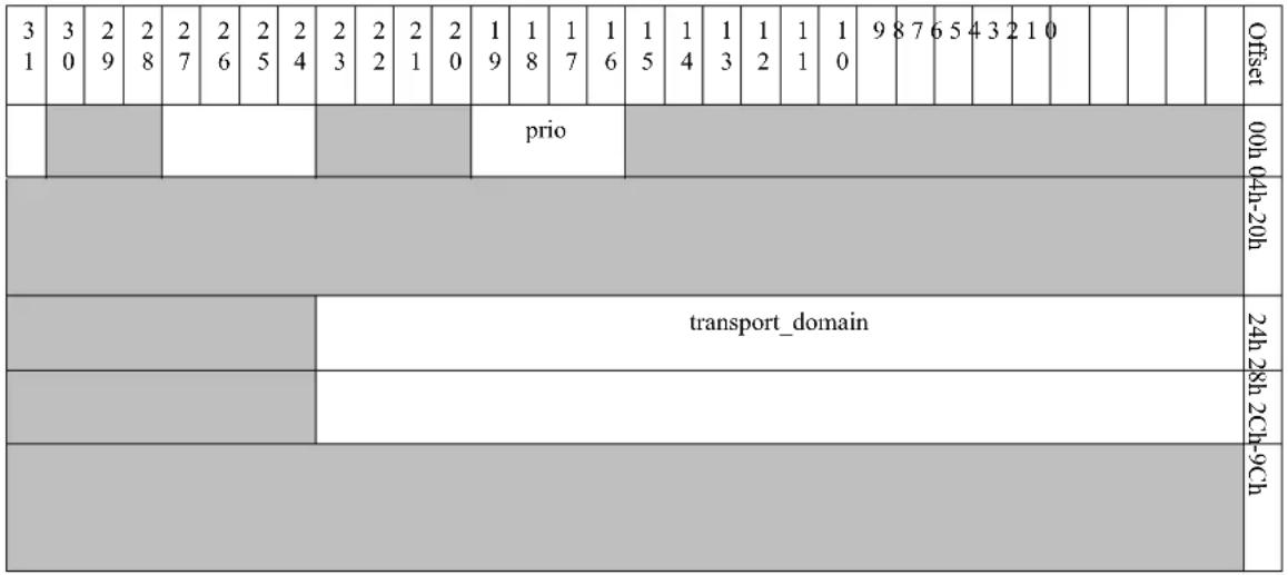 |
TIS Context fields descriptions are shown in Table 50.
Table 50 - TIS Context Fields
| Offset Bits Name Description | |||
| 00h | 19:16 | prio | Ethernet Priority in prio[3:1]. |
| 24h | 23:0 | transport_domain | Transport Domain ID. |
To modify a TIS, software provides a bitmask of the various fields that are being changed (bitmask not relevant to CREATE_TIS command). The following table summarizes the bitmasks and the supported state transitions where bits can be set:
Table 51 - MODIFY_TIS Bitmask
| Bit Field | CREATE | MODIFY | |
| 0 | prio | R | O |
| NONE | transport_domain | R | |
Legend
• R - Required parameter
• O - Optional parameter
7.7 Receive Queue (RQ)
The Receive Queue (RQ) object holds the destination for incoming packets/messages including certain offloads. RQs are attached to a TIR/Sniffer and report completions to their completion queue.
Multiple RQ types are supported: memory RQ type (which can be inline memory or RMP). Inline memory RQs include a work queue that is used to handle the incoming data memory delivery. RMP RQs do not have individual buffer to handle the incoming data but rather point to an RMP object, which can be shared across multiple RQs. The RMP object provides memory for handling incoming messages. RMP objects are described in detail in Section 7.10, “Receive Memory Pool (RMP),” on page 104. RQ context is subject to a well defined state transitions as illustrated in Figure 16.
Figure 16: RQ States
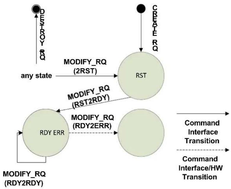
flowchart
graph TD
    A["Start State"] -->|any state| B["RST"]
    B -->|MODIFY_RQ (2RST)| C["Modify_RQ (RST2RDY)"]
    C -->|MODIFY_RQ (RDY2RDY)| D["Modify_RQ (RDY2ERR)"]
    D --> E["End"]
    F["Start State"] -->|CREATE_RQ| G["Command Interface Transition"]
    G --> H["Command Interface/HW Transition"]
    H --> I["Command Interface Transition"]
RQ context is created through the CREATE_RQ command. The context can be then modified according to the RQ state machine through the MODIFY_RQ command. It can be queried through the QUERY_RQ command. When finalized, RQ context is destroyed through the DESTROY_RQ command.
The support of RQs and the number of supported RQs is reported via the QUERY_HCA command through the log_max_rq parameter.
RQ Context format is shown in Table 52.
Table 52 - RQ Context Format
| 31 | 30 | 29 | 28 | 27 | 26 | 25 | 24 | 23 | 22 | 21 | 20 | 19 | 18 | 17 | 16 | 15 | 14 | 13 | 12 | 11 | 10 | 9 | 8 | 7 | 6 | 5 | 4 | 3 | 2 | 1 | 0 | Offset | |||||
| rlkey | vlan strip disable | mem_rq_type | state | flush in error en | 00h | ||||||||||||||||||||||||||||||||
| user_index | 04h | ||||||||||||||||||||||||||||||||||||
| eqn | 08h | ||||||||||||||||||||||||||||||||||||
Table 52 - RQ Context Format
| 31 | 30 | 29 | 28 | 27 | 26 | 25 | 24 | 23 | 22 | 21 | 20 | 19 | 18 | 17 | 16 | 15 | 14 | 13 | 12 | 11 | 10 | 9 | 8 | 7 | 6 | 5 | 4 | 3 | 2 | 1 | 0 | Offset |
| 0Ch | ||||||||||||||||||||||||||||||||
| rmpn | 10h 14h 18h-2Ch | |||||||||||||||||||||||||||||||
| 30h... | ||||||||||||||||||||||||||||||||
| wq( See Table 54, “Work Queuc (WQ) Format,” on page 93) | ||||||||||||||||||||||||||||||||
RQ Context fields descriptions are shown in Table 53.
Table 53 - RQ Context Fields
| Offset Bits Name Description | |||
| 00h 31 nkey Reserved LKey enable. | When set the reserved LKey can be used on the RQ. | ||
| 28 vlan_strip_disable VLAN Stripping Disable0 - strip VLAN from incoming Ethernet frames1 - do not strip VLAN from incoming Ethernet frames | |||
| 27:24 mem_rq_type Memory RQ Type0x0: MEMORY_RQ_INLINE - Inlined memory queue0x1: MEMORY_RQ_RMP - RMP, RQ points to a remote memory pool | |||
| 23:20 state RQ state0x0: RST0x1: RDY0x3: ERRFor QUERY_RQ - the current state is returnedFor MODIFY_RQ - the requested state is specifiedSee Section 7.7.1, “RQ States Summary,” on page 96 for further details. | |||
| 18 flush_in_error_en If set, and when RQ transitions into error state, the hardware will flush in error WQEs that were posted and WQEs that will be posted to an RQ. Otherwise, when RQ enters an error state, HW is not forced to flush in error all the WQEs, but still can generate completion.Reserved for mem_rq_type == MEMORY_RQ_RMP.For more details related to RQ Error behavior See Section 7.7.2, “RQ Error Semantics,” on page 97. | |||
| 04h | 23:0 | user_index | User_index - an opaque identifier which software sets, which is reported to the Completion Queue.Reserved if HCA_CAP.cqe_version==0. |
| 08h | 23:0 | cqn | Completion Queue Number. |
Table 53 - RQ Context Fields
| Offset Bits Name Description | |||
| 10h | 23:0 | rmpn | RMP number. Reserved for non RMP RQs. |
| 30h... 1600 wq | ( See Table 54, “Work Queue (WQ) Format,” on page 93) | Work Queue. | |
Table 54 summarizes the work queue fields and their applicability to send queues and receive queues.
Table 54 - Work Queue (WQ) Format
| 31 | 30 | 29 | 28 | 27 | 26 | 25 | 24 | 23 | 22 | 21 | 20 | 19 | 18 | 17 | 16 | 15 | 14 | 13 | 12 | 11 | 10 | 9 | 8 | 7 | 6 | 5 | 4 | 3 | 2 | 1 | 0 | Offset | |||||
| wq_type | wq_signature | end_padding_mode | 00h | ||||||||||||||||||||||||||||||||||
| page_offset lwm | 04h | ||||||||||||||||||||||||||||||||||||
| pd | 08h | ||||||||||||||||||||||||||||||||||||
| uar_page | 0Ch | ||||||||||||||||||||||||||||||||||||
| dbr_addr[63:32] | 10h | ||||||||||||||||||||||||||||||||||||
| dbr_addr[31:0] | 14h | ||||||||||||||||||||||||||||||||||||
| hw_counter | 18h | ||||||||||||||||||||||||||||||||||||
| sw_counter | 1Ch | ||||||||||||||||||||||||||||||||||||
| log_wq_stride | log_wq_pg_sz log_wq_sz | 20h,28h,BCh | |||||||||||||||||||||||||||||||||||
Table 54 - Work Queue (WQ) Format
| 31 | 30 | 29 | 28 | 27 | 26 | 25 | 24 | 23 | 22 | 21 | 20 | 19 | 18 | 17 | 16 | 15 | 14 | 13 | 12 | 11 | 10 | 9 | 8 | 7 | 6 | 5 | 4 | 3 | 2 | 1 | 0 | Offset |
| pas[0] | C0h-C4h | |||||||||||||||||||||||||||||||
| pas[1] | C8h-CCh | |||||||||||||||||||||||||||||||
| ... | ... | |||||||||||||||||||||||||||||||
Work Queue fields descriptions are shown in Table 55.
Table 55 - Work Queue (WQ) Fields
| Offset Bits Name Description | SQ | RQ | RMP | ||||||
| 00h 31:28 wq_type | WQ type | 0x0: WQ_LINKED_LIST - Linked List0x1: WQ_CYCLIC - Cyclic DescriptorsSend Queue WQ must be set to 1. | v v | v | |||||
| 20:16 | page_offset | Page offset in offset in quanta of (page_size / 64) | v | v | v | ||||
| 15:0 | lwm | Limit Water Mark when WQE count drops below this limit, an event is fired.0- Disabled | v | ||||||
| 08h | 23:0 | pd | Protection Domain.Used for accessing data through WQEs (scatter/gather). | v v | v | ||||
| 0Ch | 23:0 | uar_page | UAR number allocated for ringing DoorBells for this WQ.For RQ this field is required only if cd_slave is enabled otherwise this field is reserved. | v | |||||
| 10h | 31:0 | dbr_addr[63:32] | Physical address bits of DB Record | v | v | v | |||
| 14h | 31:0 | dbr_addr[31:0] | Physical address bits of DB Record | v | v | v | |||
Table 55 - Work Queue (WQ) Fields
| Offset | Bits | Name | Description | SQ | RQ | RMP |
| 18h | 31:0 | hw_counter | Current HW stride indexPoints to the next stride to be consumed by HW). Bits [31:16] are reserved.This field is available through the QUERY commands only. Otherwise reserved. | v v | v | |
| 1Ch | 31:0 | sw_counter | Current SW WQ WQE indexPoints to the next stride to be produced by SW. Bits [31:16] are reserved.This field is available through the QUERY commands only. Otherwise reserved. | v v | v | |
| 20h | 19:16 | log_wq_stride | The size of a WQ stride equals 2^log_wq_stride. | v | v | v |
| 12:8 | log_wq_pg_sz | Log (base 2) of page size in units of 4Kbyte | v | v | v | |
| 4:0 log_wq_sz | WQ size in Bytes is 2^(log_wq_size + log_wq_stride)log_wq_sz must be less than HCA_CAP.log_max_wq-size | v v | v | |||
| C0h-... | 64 | pas[...] (See Table 138, "Physical_Address_Structure (PAS) Layout," on page 193) | Array of physical address structure (PAS) that map the work queue. | v v | v | |
To modify an RQ, software provides a bitmask of the various fields that are being changed. Table 56 summarizes the bitmasks and the supported state transitions where bits can be set:
Table 56 - CREATE_RQ and MODIFY_RQ Bitmask
| Bit | Field | CREATE_RQ | RST2RDY | RDY2RDY | RDY2ERR | 2RST | |
| RQ | none | state | R | R | R | R | R |
| none | rlkey | R | |||||
| none | cs | R | |||||
| 1 | vsd | R | O | O | |||
| none | rq_type | R | |||||
| none | rq_index | R | |||||
| none | cqn | R | |||||
| none | rmpn | R | |||||
| none | flush_in_error_en | R | |||||
| WQ | none | wq_type | R | ||||
| none | wq_signature | R |
Table 56 - CREATE_RQ and MODIFY_RQ Bitmask
| Bit | Field | CREATE_RQ | RST2RDY | RDY2RDY | RDY2ERR | 2RST | |
| none end_padding_mode R | |||||||
| none R | |||||||
| none log_wq_pg_sz R | |||||||
| none log_wq_stride R | |||||||
| none log_wq_size R | |||||||
| none page_offset R | |||||||
| none pd R | |||||||
| none uar_page N/A | |||||||
| none dbr_addr R | |||||||
| none pas[...] R | |||||||
Legend
• R - Required parameter
- O - Optional parameter
7.7.1 RQ States Summary
Table 57 summarizes the RQ states.
Table 57 - RQ States Summary
| RMP | TIR Associated? | RQ State | Description |
| None (RQ type is Direct) | ALL | RST | Doorbells are not processed and WQEs are not flushed.Incoming messages are silently dropped or never reach the Receive Queue.Note: Prior to moving an RQ from RST into RDY state, the device driver has to initialize RQ DoorBell counter to zero. |
| No | RDY | Work Requests can be submitted to the Receive Queue.Incoming messages never reach the RQ. | |
| YES | RDY | Work Requests can be submitted to the Receive Queue.Incoming messages are processed normally. | |
| ALL | ERR | If RQ.flush_in_error_en is enabled, Work Requests submitted to the Receive Queue are flushed in error. Otherwise, RQ is not forced to flush the posted Work Requests but Work Requests cannot be submitted to the Receive Queue and incoming messages are silently dropped or never reach the RQ.See Section 7.7.2, “RQ Error Semantics,” on page 97. |
Table 57 - RQ States Summary
| RMP | TIR Associated? | RQ State | Description |
| With RMP Memory RQ type is MEMO-RY_RQ_RMP RMP state is RDY | ALL RST, | ERR | Work Requests can be submitted to the corresponding RMP. Incoming messages are silently dropped or never reach the RQ. |
| NO | RDY | Work Requests can be submitted to the corresponding RMP. Incoming messages never reach the RQ. | |
| YES | RDY | Work Requests can be submitted to the corresponding RMP. Incoming messages are processed normally. | |
| With RMP. Memory RQ type is MEMO-RY_RQ_RMP RMP state is ERR | ALL RST, | ERR | Work Requests can be submitted to the corresponding RMP. Incoming messages are silently dropped or never reach the RQ. |
| ALL | RDY | Work Requests can be submitted to the corresponding RMP. When an RQ tries to dequeue a WQE from the corresponding RMP, the RQ is placed in the ERR state and RQ Catastrophic Error event is generated. If not, the TIR that is connected to an RQ incoming messages never reach the RQ. |
7.7.2 RQ Error Semantics
7.7.2.1 Memory RQ with Inline Memory Queue
A memory RQ with an inline receive memory queue (not connected to RMP) supports the following completion modes when it enters an error state:
- Flush in error WQEs that were posted and WQEs that will be posted to the RQ.
- When RQ enters Error state, it is not forced to flush in error all the WQEs but can still generate completions.
RQ.flush_in_error_en flags set the completion mode. For more details related to behavior of flush_in_error_en flag please refer to Table 52, "RQ Context Format," on page 91.
7.7.2.2 RQ Associated with RMP
Error semantics on RQs attached to RMPs are slightly different from those of regular RQs. If an RQ enters the error state, the WQEs that have already been de-queued from the RMP are completed with error or completely flushed. The rest of the WQEs are left intact in the RMP and the RMP state is not affected by the error.
If failure occurs while de-queuing a WQE, the RMP moves to the error state and an affiliated asynchronous event is generated. While the RMP is in the error state, RQs can be attached or detached from the RMP and WQEs can still be posted. RQs that attempt to dequeue a WQE from the RMP are moved to the error state by hardware.
To clean up an RMP in error state, SW has to destroy all RQs that are attached to the RMP and then destroy the RMP. After all resources have been destroyed, they can be reopened again, with the RMP opened first.
RQs attached to RMP flushing semantics differ from regular RQs flushing semantics. While regular RQs can be configured to flush all WQEs that are posted after an error is introduced, RMPs tend to minimize the flushing. Since they are shared, flushing WQEs can impact other RQs shar-
ing the same RMP. Therefore, if an error is detected on an RQ attached to an RMP, only WQEs that have already been de-queued from the RMP for processing by the errant RQ are flushed. The rest of the WQEs on the RMP are unaffected by the error.
After RMP flushing is complete, the 'Last WQE Reached' event (See Table 82, "Event_data Field - SQ/RQ Events Layout," on page 136) is generated for the errant RQ. (If no WQEs need to be flushed, this event is generated as the RQ enters the error state.) Thus, no new completions are reported on the specific RQ until the RQ state is modified.
7.8 RQ Table (RQT)
RQT object holds a table of RQs. TIR points to RQT and uses it as indirection table. RQT allows to dispatch the packet only to single RQ from the table, accessed by table index.
RQT context is created through the CREATE_RQT command. The context can be then modified through the MODIFY_RQT command. It can be queried through the QUERY_RQT command. When finalized, RQT context is destroyed through the DESTROY_RQT command.
The support of RQT and the number of supported RQTs is reported via the QUERY_HCA command through the log_max_rqt parameter.
Table 58 - RQT Context Format
| 31 | 30 | 29 | 28 | 27 | 26 | 25 | 24 | 23 | 22 | 21 | 20 | 19 | 18 | 17 | 16 | 15 | 14 | 13 | 12 | 11 | 10 | 9 | 8 | 7 | 6 | 5 | 4 | 3 | 2 | 1 | 0 | Offset 00h-10h | ||||||
| rqt_max_size | 14h | |||||||||||||||||||||||||||||||||||||
| rqt_actual_size | 18h1Ch-ECh | |||||||||||||||||||||||||||||||||||||
| rq_num[0] | F0h | |||||||||||||||||||||||||||||||||||||
| rq_num[1] | F4h | |||||||||||||||||||||||||||||||||||||
| ... | ||||||||||||||||||||||||||||||||||||||
RQT Context fields descriptions are shown in Table 59.
Table 59 - RQT Context Fields
| Offset Bits Name Description | |||
| 14h | 15:0 | rqt_max_size | Sets the max allowed rqt_actual_size. If command attempts to set rqt_actual_size higher than rqt_max_size the command fails and RQT does not change. This field must be set according to HCA_CAP.log_max_rqt_size limitation, otherwise the command fails.rqt_max_size must be power of two. |
Table 59 - RQT Context Fields
| Offset Bits Name Description | |||
| 18h | 15:0 | rqt_actual_size | The number of entries in this Receive Queues Table.rqt_actual_size must be power of two and <= rqt_max_size. |
| F0h-... 23:0 rq_num [...] Table of RQs. | Note that the same RQN is allowed to appear multiple times.This table can be used as indirection table for RSS. | ||
7.9 Send Queue (SQ)
The Send Queue (SQ) object holds the descriptor ring used to send outgoing messages and packets. The SQ is attached to a TIS and reports completions to its completion queue.
SQ context is subject to a well defined state transitions as illustrated in Figure 17.
Figure 17: SQ States
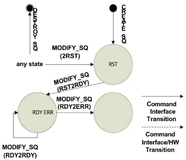
flowchart
graph TD
    A["Start"] --> B{RDY ERR}
    B -->|MODIFY_SQ (RDY2RDY)| C["RDY ERR"]
    C -->|MODIFY_SQ (RST2RDY)| D["RST"]
    D -->|MODIFY_SQ (2RST)| E["Any state"]
    E -->|CREATE_SQ| F["End"]
    B -->|COMMAND Interface Transition| G["Command Interface Transition"]
    G --> H["Command Interface/HW Transition"]
SQ context is created through the CREATE_SQ command. The context can be then modified according to the SQ state machine through the MODIFY_SQ command. It can be queried through the QUERY_SQ command. When finalized, SQ context is destroyed through the DESTROY_SQ command.
The support of SQs and the number of supported SQs is reported via the QUERY_HCA_CAP command through the log_max_sq parameter. SQs are typically associated with a single TIS. For support of SQ association into multiple TISes, check the QUERY_HCA_CAP max_tis_per_sq. SQ Context format is shown in Table 60.
Table 60 - SQ Context Format
| 31 | 30 | 29 | 28 | 27 | 26 | 25 | 24 | 23 | 22 | 21 | 20 | 19 | 18 | 17 | 16 | 15 | 14 | 13 | 12 | 11 | 10 | 9 | 8 | 7 | 6 | 5 | 4 | 3 | 2 | 1 | 0 | Offset | |||||
| rlkey | frc | flush in error en | min_w qc_in-line_ mode | state | 00h | ||||||||||||||||||||||||||||||||
| user_index | 04h | ||||||||||||||||||||||||||||||||||||
| eqn | 08h 0Ch 10h 14h 18h 1Ch | ||||||||||||||||||||||||||||||||||||
| tis_lst_sz | 20h 24h-28h | ||||||||||||||||||||||||||||||||||||
| tis_num[0] | 2Ch | ||||||||||||||||||||||||||||||||||||
| wq( See Table 54, “Work Queue (WQ) Format,” on page 93) | 30h... | ||||||||||||||||||||||||||||||||||||
SQ Context fields descriptions are shown in Table 61.
Table 61 - SQ Context Fields
| Offset Bits Name Description | |||
| 00h 31 n | lkey Reserved | LKey enable. | When set the reserved LKey can be used on the SQ. |
| 29 frc Fast | Register Enable. | When set, the SQ supports Fast Register WQEs. | |
| 28 | flush_in_error_en | If set, and when SQ transitions into error state, the hardware will flush in error WQEs that were posted and WQEs that will be posted to SQ. Otherwise, when SQ enters an error state HW is not forced to flush in error all the WQEs.For more details related to SQ Error behavior refer to Section 7.9.2, “SQ Error Semantics,” on page 103. | |
| 26:24 min_wqe_inline_mode Sets the inline mode for the SQ.min_wqe_inline_mode defines the minimal required inline headers in Eth Segment of the SQ’s WQEs. If Eth Segment of the WQE does not contain the required inlined headers, the packet is silently dropped.Note: SQ.min_wqe_inline_mode must be >= Nic_vport.min_sq_wqe_inline_mode. See Table 15, “NIC_Vport Context Layout,” on page 66. For more details - See Section 7.4.4.1.2, “Eth Segment and Padding Segment,” on page 76. | |||
| 23:20 state | SQ state | 0x0: RST0x1: RDY0x3: ERRFor QUERY_SQ - the current state is returnedFor MODIFY_SQ - the requested state is specifiedFor further details See Section 7.9.1, “SQ States Summary,” on page 103. | |
| 04h | 23:0 | user_index | User_index - an opaque identifier which software sets, which will be reported to the Completion Queue.Reserved if HCA_CAP.cqe_version=0. |
| 08h | 23:0 | cqn | Completion Queue Number |
| 20h | 31:16 | tis_lst_sz | The number of entries in the list of TISes. This is the list of Transport Interface Send (TISes) that are associated with this SQ. |
| 2Ch | 23:0 | tis_num[0] | List of TIS numbers.Note: in this revision of PRM, only a single TIS is supported |
| 30h... | 1600 | wq(See Table 54, “Work Queue (WQ) Format,” on page 93) | Work Queue |
To modify an SQ, software provides a bitmask of the various fields that are being changed. Table 62 summarizes the bitmasks and the supported state transitions where bits can be set.
Table 62 - CREATE_SQ and MODIFY_SQ Bitmask
| Bit Field | CREATE_SQ | RST2RDY | RDY2RDY | RDY2ERR | 2RST | ||
| SQ none state R | R | R R R | |||||
| none rlkey R | |||||||
| none fre R | |||||||
| none sq_index R | |||||||
| none cqn R | |||||||
| none tis_lst_sz R | |||||||
| none tis_num[0] | R | ||||||
| none flush_in_error_cn | R | ||||||
| none min_wqe_inline_mode | R | ||||||
| 0 | packet_pacing_rate_limit_index | R | O | O | O | O | |
| WQ | none | wq_type | R | ||||
| none wq_signature | R | ||||||
| none end_padding_mode | N/A | ||||||
| none cd_slave | R | ||||||
| none log_wq_pg_sz | R | ||||||
| none log_wq_stride | R | ||||||
| none log_wq_size | R | ||||||
| none page_offset | R | ||||||
| none lwm | N/A | ||||||
| none pd | R | ||||||
| none uar_page | R | ||||||
| none dbr_addr R | |||||||
| none pas[...] | R | ||||||
Legend
• R - Required parameter
- O - Optional parameter
• N/A - Not Applicable (irrelevant for SQs)
7.9.1 SQ States Summary
Table 63 summarizes the SQ states.
Table 63 - SQ States Summary
| SQ State | Description |
| RST Doorbells are not processed and WQEs are not flushed.Note: Prior to moving an SQ from RST into RDY state, the device driver has to initialize SQ DoorBell counter to zero. | |
| RDY Work requests are processed normally. | |
| ERR | If SQ.flush_in_error_en is enabled, Work Requests submitted to the SQ are flushed in error. Otherwise, an SQ is not forced to flush the posted Work Requests but Work Requests cannot be submitted to the Send Queue.See Section 7.9.2, “SQ Error Semantics,” on page 103. |
7.9.2 SQ Error Semantics
SQ supports the following completion modes when it enters an error state:
- Flush in error WQEs that were posted and WQEs that will be posted to SQ.
- When SQ enters Error state it is not forced to flush in error all the WQEs.
SQ.flush_in_error_en flags set the completion mode. For more details related to the behavior of flush_in_error_en flag please refer to Table 60, "SQ Context Format," on page 100.
7.9.3 Send WQE Inline Header
Each SQ's WQE must contain a minimal amount of packet headers inlined in the WQE's Eth Segment. Send WQEs with inline headers less than the required are dropped. The device supports different inline modes that are described in Section 7.9.3.1, "Inline Modes," on page 104, each inline mode requires a different minimal number of inline headers. The required inline modes can be queried by HCA_CAP.wqe_inline_mode.
HCA_CAP wqe inline modes:
- Mode 0 - The inline mode is L2.
- Mode 1 - The minimal required inline headers are set by SQ.min_wqe_inline_mode. Send WQEs with inline headers less than the required by SQ.min_wqe_inline_mode are dropped. The device supports different inline modes that are described in Section 7.9.3.1, "Inline Modes," on page 104. Each inline mode requires a different minimal number of inline headers. NIC Vport Context defines the minimal inline mode required for all SQs that belong to NIC Vport (See Section 7.3, "NIC_Vport Context - NIC Virtual Port Context," on page 66). An attempt to create SQ with inline mode < minimal required by the Vport NIC will fail. SW must query the required minimal inline header by reading the NIC Vport Context field using QUERY_NIC_VPORT_- CONTEXT (my Vport). On SQ creation, the NIC driver must set the minimal required inline header for the created SQ by setting SQ.min_wqe_inline_mode field. SQ.min_wqe_inline_mode must be >= NIC Vport Context min_sq_wqe_inline_mode. Mode 2 - No inline headers are required.
7.9.3.1 Inline Modes
- Mode 0: None - no inline headers are required.
- Mode 1: L2 - for LLC/SNAP frames, the packet inlined headers must include Max (17 Bytes, L2 headers till the last EtherType). For non LLC/SNAP frames, the packet inlined headers must include L2 headers till the last EtherType.
- Mode 2: IP - for packets that carry IP header, the packet inlined headers must include up to the end of the IP header. For packets that do not carry IP header, “L2” mode rules should be applied.
- Mode 3: TCP/UDP - for packets that carry TCP/UDP header, the packet inlined headers must include up to the end of the TCP/UDP header. For packets that do not carry TCP/UDP header, "IP" mode rules should be applied.
- Mode 4: reserved.
- Mode 5: Inner L2 - for tunneled packet, the packet inlined headers must include up to the end of the last inner EtherType. For non-tunneled packets, “TCP/UDP” mode rules should be applied.
- Mode 6: Inner IP - for tunneled packets that carry inner IP header, the packet inlined headers must include up to the end of the inner IP header. For packets that do not carry inner IP header, “inner L2” mode rules should be applied.
- Mode 7: Inner TCP/UDP - for tunneled packets that carry inner TCP/UDP header, the packet inlined headers must include up to the end of the inner TCP/UDP header. For packets that do not carry inner TCP/UDP header, “inner IP” mode rules should be applied.
7.10 Receive Memory Pool (RMP)
The Receive Memory Pool (RMP) object holds the destination for incoming packets/messages that are routed to the RMP through RQs. RMP enables sharing of memory across multiple Receive Queues. Multiple Receive Queues can be attached to the same RQ and consume memory from that shared poll.
When using RMPs, completions are reported to the CQ pointed to by the RQ.
RMP context is subject to a well defined state transitions as illustrated in Figure 18.
Figure 18: RMP States
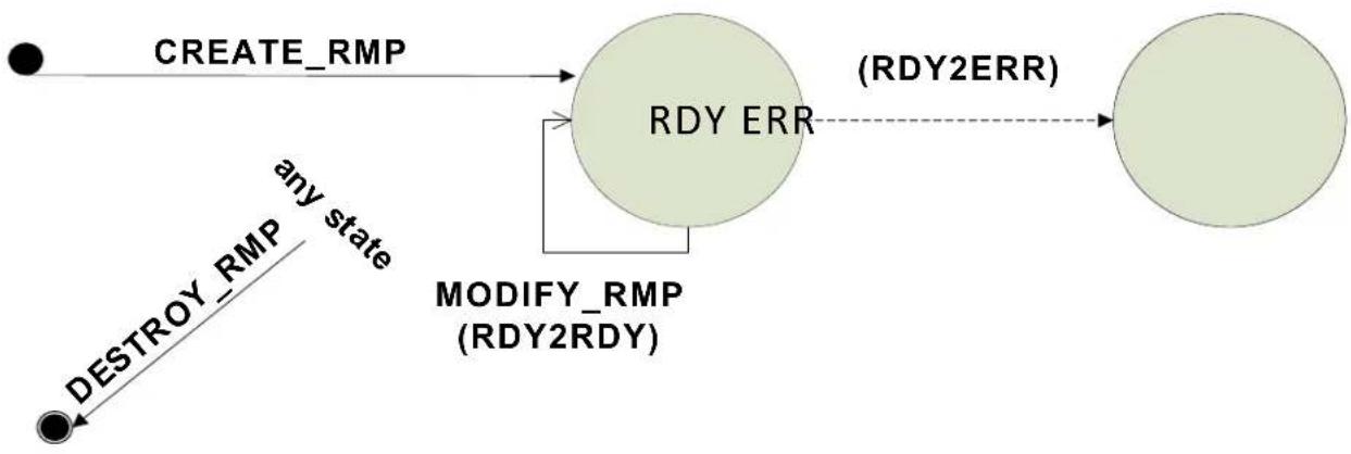
flowchart
graph TD
    A["CREATE_RMP"] --> B["RDY ERR"]
    B --> C["(RDY2ERR)"]
    D["DESTROY_RMP"] -->|any state| B
    B --> E["MODIFY_RMP (RDY2RDY)"]
Legend:
Command Interface Transition Command Interface/HW Transition
RMP context is created through the CREATE_RMP command. The context can be then modified according to the RMP state machine through the MODIFY_RMP command. It can be queried through the QUERY_RMP command. When finalized, RMP context is destroyed through the DESTROY_RMP command.
The support of RMP and the number of supported RMPs is reported via the QUERY_HCA_CAP command through the log_max_rmp parameter.
RMP Context format is shown in Table 64.
Table 64 - RMP Context Format
| 31 | 30 | 29 | 28 | 27 | 26 | 25 | 24 | 23 | 22 | 21 | 20 | 19 | 18 | 17 | 16 | 15 | 14 | 13 | 12 | 11 | 10 | 9 | 8 | 7 | 6 | 5 | 4 | 3 | 2 | 1 | 0 | Offset | |||||
| state | 00h | ||||||||||||||||||||||||||||||||||||
| basic_cyclic_rev_wqe | 04h 08h-1Ch | ||||||||||||||||||||||||||||||||||||
| wq( See Table 54, “Work Queue (WQ) Format,” on page 93) | 30h... | ||||||||||||||||||||||||||||||||||||
RMP Context fields descriptions are shown in Table 65.
Table 65 - RMP Context Fields
| Offset Bits Name Description | |||
| 00h 23:20 state RMP state | 0x1: RDY0x3: ERRFor QUERY_RMP - the current state is returnedFor MODIFY_RMP - the requested state is specifiedMust be RDY for CREATE_RMPFor further information, See Section 7.10.1, “RMP States Summary,” on page 107 | ||
| 04h | 31 | basic_cyclic_rcv_wqe | 0: cyclic receive wqe always includes the 16 byte of ctrl (signature field).1: cyclic receive wqe includes the 16 bytes of ctrl only when wq_signa-ture==1.Valid only if HCA_CAP. basic_cyclic_rcv_wqe==1 and wq.wq_-type==WQ_CYCLIC |
| 30h-... 1 | 600 wq | ( See Table 54, “Work Queue (WQ) Format,” on page 93) | Work Queue |
To modify an RMP, software provides a bitmask of the various fields that are being changed. Table 66 summarizes the bitmasks and the supported state transitions where bits can be set.
Table 66 - CREATE_RMP and MODIFY_RMP Bitmask
| Bit Field | CREATE_RMP | RDY2RDY | ||
| RMP | none | state | R | R |
| WQ | none | wq_type | R | |
| none | wq_signature | R | ||
| none | cnd_padding_mode | R | ||
| none | log_wq_pg_sz | R | ||
| none | log_wq_stride | R | ||
| none | log_wq_size | R | ||
| none | page_offset | R | ||
| 0 | lwm | R | O | |
| none | pd | R | ||
| none | uar_page | N/A | ||
| none | dbr_addr | R | ||
Table 66 - CREATE_RMP and MODIFY_RMP Bitmask
| Bit | Field | CREATE_RMP | RDY2RDY | |
| none pas[...] R | ||||
Legend
- R - Required parameter
- O - Optional parameter
7.10.1 RMP States Summary
RMP implements the two following states:
- RDY – this is the initial state. In this state software can post WQEs to the RMP. RMP provides WQEs to RQs attempting to consume WQEs normally.
- ERR – in this state software can post WQEs to the RMP. RMP does not provide WQEs to RQs attempting to consume WQEs; instead it causes the RQs to transition into the ERR state.
For further details on RMP states with correlation to RQ states, refer to Section 7.7.1, “RQ States Summary,” on page 96.
7.11 Flow Table
Packet processing by the device requires classifying them into flows. Each flow may have a different processing path and may lead to a different destination. Packet classification is done using the Flow Table mechanism.
7.11.1 Position in Processing Flow
Flow tables are used in several stages of packet processing flow. Each stage has a unique set of Flow Tables. The following processing stages using Flow Tables are defined:
• NIC Receive
• N I C T r a n s m i t
Each Flow Table type of the above list may supports a subset of the Flow Table capabilities and may have special characteristics and limitations described in “Characteristics of Flow Table Types”.
7.11.2 General Structure
The Flow Table is built as a ternary content-addressable memory (TCAM). Each entry in the Flow Table represents a Flow by defining a match criteria and a match value. Packets processed by the Flow table attempt to match every entry, in order, starting at entry 0. The first entry that matches the packet defines the processing actions that should be immediately applied to the packet. The matching Flow is considered as 'hit' by the packet.
7.11.2.1 Match Criteria
The Flow Table entry match criteria is defined by a set of masks.
- Packet header field - fields derived from parsing the packet:
- MAC header - Source Address, Destination Address, Ethertype
• VLAN header - VLAN ID, Priority (PCP), CFI/EDI - IPv6(v4) header - Source Address, Destination Address, Traffic Class (Type Of Service), Next Header (Protocol) TCP header - Source Port, Destination Port, Flags
- UDP header - Source Port, Destination Port, Flags
• VXLAN header - VNI
• GRE header - Key, Protocol - For supported encapsulation packets MAC, VLAN, TCP and UDP headers for the inner packet
Set bit in a mask means the appropriate bit in the appropriate field in the match value should be compared to the corresponding bit from the processed packet. Cleared bit means the appropriate bit in the appropriate field in the match value is ignored.
7.11.2.2 Processing Actions
When a packet matches a Flow, the actions specified for the Flow are applied. The possible actions for a Flow are as follows:
- Drop - Packet processing is stopped
- Forward - Packet processing continues in one or more processing entities specified in the Flow Table entry.
- Allow - Packet processing continues in a well-known pre-defined manner.
- Count - increment a packet counter, and add the packet size to a byte counter.
When multiple actions are set for the same Flow (if applicable), the order of their application is not defined.
Note: Drop, Forward and Allow actions a Mutually Exclusive. One of them must be applied to every Flow.
7.11.2.3 Flow Table Chaining
Packet classification may require a hierarchical approach. For that purpose, a Flow with a Forward action may specify another Flow Table as the next processing entity for the packet. The destination Flow Table must be of the same type (i.e. belongs to the same processing stage). A packet matching this flow will continue to search for another match in the destination Flow Table starting at the first Flow. For every Flow Table type there is a single root table.
Chaining Flow Tables must never create loops.
7.11.2.4 Multi-Processing Paths
When the same packet needs to be processed multiple times, a Flow with a Forward action may indicate multiple destination processing entities. A packet matching this flow will be processed at each processing entity specified in the Flow separately. This mechanism may be used for multicasting the packet to several destinations.
Multi-processing paths to multiple Flow Tables must never be nested.
7.11.2.5 Default Behavior
Each Flow Table must be explicitly allocated before it may be used. In the absence of the root Flow Table in a given processing stage, a default behavior is applied for all packets going through this stage. The same default behavior is applied for a packet that matches a Flow with Default action or a packet that does not match no any Flow.
Each Flow Table Type has a defined default behavior described in “Characteristics of Flow Table Types”. This behavior can be overridden by allocating the root Flow Table, and defining a Flow with an empty match criteria and the required action.
7.11.2.6 Invalid Flows
Prior to the definition of a Flow in a Flow Table or after deleting a Flow, the Flow is Invalid. Packets never 'hit' Invalid Flows. If during lookup on a certain Flow Table an Invalid Flow is encountered, the packet simply moves on to the next Flow in the table in attempt to find a match.
7.11.2.7 Packet Classification Ambiguities
The match criteria of a single Flow may include any number of fields. It is the responsibility of the programmer to assure that once packet classification is done, all fields that define the packet class were matched, and no ambiguity remains.
For example, matching IP destination address does not guarantee that the packet is an IP packet. The Flow (or any of the Flows leading to it through Flow Table Chaining) must match the Ether-type field of the packet to assure an IP packet of the correct version.
In addition, a flow should not match non-existing fields of a packet, as defined by the packet classification process. For example, matching destination IP address is not allowed for flows matching Ethertype to a non-IP value.
Since packet classification process may span multiple flows in multiple Flow Tables, packet classification ambiguities or non-existing field matching should be avoided by the programmer. Failing to do so may result in undefined behavior, either failing the flow configuration or causing errors in packet classification.
7.11.2.8 Flow Statistics
Each Flow may collect statistics of the traffic matching the flow. The statistics are gathered in a flow counter, collecting the number of packets matching the flow and their total Byte count.
7.11.2.9 Flow Tagging
Each Flow may be marked with a tag, the attached packet matching the Flow, and exposed in the Completion report (CQE) flow_tag field. The tag could be used to identify the Flow through which the packet was processed. The CQE will reflect last tag encountered during packet processing. An unmarked Flow, will not modify the current tag attached to the packet.
Note: A Flow tag should not be set for Flows beyond Multi-Processing split, if a Flow tag was already set prior to the split. The value of the tag in the CQE is not defined in these cases.
7.11.3 Configuration Interface
7.11.3.1 Allocating a Flow Table
A new Flow Table is allocated using the “CREATE_FLOW_TABLE - Allocate a New Flow Table” command. The processing stage that the Flow Table belongs to is indicated in table_type field. The support for each of the Flow Table types is indicated by ft_support field in “Flow Table NIC Capabilities Layout”, under the appropriate flow_table_properties_
The number of Flows in the table is indicated in log_size field. The table size must not exceed log_max_ft_size in "Flow Table NIC Capabilities Layout", under the appropriate flow_table_properties_
7.11.3.2 Selecting the Root Flow Table
The root Flow Table for each Flow Table Type is defined, by default, as the Flow Table with level 0. Only a single Flow Table with level 0 is allowed.
Explicitly setting or replacing the root Flow Table is allowed by using SET_FLOW_TABLE_ROOT command. The new root Flow Table should be allocated prior to execution of the command. The previous root table (if exist) is not deleted. Its relevant resources need to be released explicitly if no longer needed. The support for setting the root table is indicated by HCA_CAP.modify_root.
7.11.3.3 Flow Table Level
When using an hierarchical approach for packet classification, the different hierarchies (levels) must be explicitly defined at Flow Table allocation. Chaining Flow tables must be done so a Flow in a Flow table of a certain level may only point to a Flow Table of a higher level.
When using Multi-Processing Paths, a Flow pointing to multiple Flow Tables or multiple TIRs must follow these guidelines:
- The Flow table containing this Flow must have a level lower than 64.
- The Flow tables pointed by this Flow (not relevant if the Flow points only to TIRs) must have a level equal or higher than 64. This does not apply to the last flow table in the destination list when HCA_CAP.nic_rx_multi_path_tirs = 1.
The Flow Table level is defined at allocation time by level field in "CREATE_FLOW_TABLE - Allocate a New Flow Table". It must not exceed max_ft_level in "Flow Table NIC Capabilities Layout", under the appropriate flow_table_properties_
7.11.3.3.1 Flow Table Identifier
Upon completion of the Flow Table allocation, a handler is returned in table_id field. This handler is unique for the specific Flow table type and Vport (when applicable).
7.11.3.4 Allocating a Match Criteria - Flow Groups
The match criteria of a Flow is defined before setting the actual Flow. A set of consecutive Flows in a certain Flow Table with the same match criteria is considered a Flow Groups. Flow Groups a
re allocated after the relevant Flow Table is allocated using the "CREATE_FLOW_GROUP - Define a New Flow Group" command.
The Flow Table a Flow Group belongs to is identified by the table_type, table_id and vport (when applicable) fields.
The range of Flows belonging to the Flow Group is defined by start_flow_index and end_flow_index fields. A Flow Group could be as little as a single Flow. The Flow Groups must not exceed the size of the Flow Table, and must not overlap. a Flow may only be associated with a single Flow Group.
The match criteria is given in match_criteria field, which is the set of masks as defined in "Match Criteria". Each bit in match_criteria_enable field validates a sub-set of the match_criteria.
Each mask in the match_criteria may have one of the following values:
- FULL match - the corresponding field is compared completely, all bits of the mask are set.
- NONE match - the corresponding field is completely ignored, all bits of the mask are cleared.
- PARTIAL match - some of the bits of the corresponding field are compared.
A NONE match is supported for all fields in the match_criteria. A FULL match for a field is supported if the corresponding bit of ft_field_support in “Flow Table NIC Capabilities Layout” is set. a PARTIAL match is supported if the corresponding bit of ft_field_bitmask_support in “Flow Table NIC Capabilities Layout” is set, both under the appropriate flow_table_properties_
Note: The MAC header field destination address (dmac) mask 01:00:00:00:00:00 is also supported if a FULL match is supported for this field.
7.11.3.4.1 Flow Group Identifier
Upon completion of the Flow Group allocation, a handler is returned in group_id field. This handler is unique for the specific Flow table the Flow Group is associated with.
7.11.3.5 Allocating a Flow Counter
A new flow counter is allocated using the “ALLOC_FLOW_COUNTER - Allocate a Flow Counter” command. The command returns the flow_counter_id handle to a future reference of the flow counter.
The support for flow counters in each of the Flow Table types is indicated by flow_counter field in Table 148, “Flow Table NIC Capabilities Layout,” on page 204, under the appropriate flow_table_properties_
The number of available flow counters is indicated by max_flow_counter in Table 144, "HCA Capabilities Layout," on page 196.
Note: Flow Counters are supported only for NIC Rx, RDMA Rx, Egress ACLs and Sniffer Flow Tables.
Note: Distributing the Flow Counters between the different Flow Table types (for example between the eswitch tables and the NIC tables), is outside the scope of this document and left for driver implementation.
7.11.3.6 Adding a Flow
A new Flow is defined using the “SET_FLOW_TABLE_ENTRY - Set Flow Table Entry” command.
The Flow Table a Flow belongs to is identified by the table_type, table_id and vport (when applicable) fields. The Flow Group the Flow belongs to is identified by the group_id field.
The location of the Flow inside the Flow Table is defined by the flow_index field. The location must not exceed the range of Flows defined by the Flow Group.
The match value is given in match_value field of the flow_context structure. The relevant fields inside the match value are defined by the match criteria associated with the Flow Group. Any other field is reserved and should be set to 0x0.
The Flow Tag attached to packets matching the Flow is indicated in flow_tag field. A value of 0x0 indicates and unmarked Flow, which does not modify the Flow Tag already attached to the packet.
The field action holds a list of actions to be applied if a packet matches the Flow, as defined in “Processing Actions”. Some actions may be set independently, and some are mutually-exclusive.
- Drop, Default and Forward actions are mutually-exclusive.
When a Flow has a Forward action, the number of processing entities the packet should be destined to is specified in destination_list_size. Each destination is defined by a handler destination_id and a type destination_type. The defined destination types are:
- F l o w T a b l e
• TIR
When specifying multiple destinations, the order between them is not defined. The destination list must be comprised of destinations of the same type. The number of destinations in a single Flow must not exceed log_max_destination in “Flow Table NIC Capabilities Layout”, under the appropriate flow_table_properties_
The total number of valid Flows in all Flow Tables of a single type must not exceed log_max_flow in the same capabilities structure.
When a Flow has a Count action, the number of flow counters associated with the flow is specified in flow_counter_list_size. Each counter is defined by a handle flow_counter_id. The number of destinations in a single flow must not exceed log_max_flow_counter in Table 148, “Flow Table NIC Capabilities Layout,” on page 204, under the appropriate flow_table_properties_
Note: Each TIR may only be used in a single type of Flow Table. Adding flows, in Flow Tables of different types, forwarding to the same TIR is not allowed.
7.11.3.7 Redefining a Flow
An existing flow may be modified. Flow modification is guaranteed to be atomic. That is, once the flow is modified, new packets will not act according to the old flow definition.
The modified flow must hold all requirements and restrictions applicable for any flow.
The support for modifying a flow is indicated by modify_flow_en field in QUERY_HCA_CAP (Table 150, "Flow Table Properties Layout," on page 205) for the appropriate Flow Table type. Modifying a flow is done using the SET_FLOW_TABLE_ENTRY command (See Table 427, "SET_FLOW_TABLE_ENTRY Input Structure Layout," on page 294), using opmod
value Modify.
The supported modifications are for:
- Action
- flow_tag
- Destination list (size and members)
- Flow Counter list (size and members)
Note: The modified fields should be indicated in the bitmask modify_enable. The new values are taken from the appropriate fields in the flow_context. Other fields in this context should match the original flow definition. When adding or removing a Forward/Count action, the destination/flow counter list must be modified as well.
7.11.3.8 Freeing Resources
Flows are invalidated using the “DELETE_FLOW_TABLE_ENTRY - Invalidate Flow Table Entry” command. The Flow Table a Flow belongs to is identified by the table_type, table_id (when applicable) fields. The Flow Group the Flow belongs to is identified by the group_id field. The location of the Flow inside the Flow Table is defined by the flow_index field. A Flow must be valid (previously added) to be invalidated.
Flow Groups are freed using the “DESTROY_FLOW_GROUP - De-allocate a Flow Group” command. The Flow Table a Flow Group belongs to is identified by the table_type, table_id (when applicable) fields. The Flow Group is identified by the group_id field. A Flow Group can only be freed if it was previously allocated and all the Flows associated with it are Invalid.
Flow Tables are freed using the “DESTROY_FLOW_TABLE - De-allocate a Flow Table” command. The Flow Table is identified by the table_type, table_id (when applicable) fields. A Flow Table can only be freed if it was previously allocated and all the Flow Groups associated with it are freed.
Flow Counters are freed using the “DEALLOC_FLOW_COUNTER - De-Allocate Flow Counter” command. The flow counter is identified by the flow_counter_id field. A flow counter can only be freed if it was previously allocated and all the flows associated with it are freed.
7.11.3.9 Querying Device Database
Flows may be queried using the "QUERY_FLOW_TABLE_ENTRY - Query Flow Table Entry" command. The Flow Table a Flow belongs to is identified by the table_type, table_id (when applicable) fields. The Flow Group the Flow belongs to is identified by the group_id field. The location of the Flow inside the Flow Table is defined by the flow_index field. A Flow must be valid (previously added) to be queried.
Flow Groups may be queried using the “QUERY_FLOW_GROUP - Query Flow Group” command. The Flow Table a Flow Group belongs to is identified by the table_type, table_id and vport (when applicable) fields. The Flow Group is identified by the group_id field. A Flow Group must be allocated to be queried.
Flow Tables may be queried using the “QUERY_FLOW_TABLE - Query Flow Table” command. The Flow Table is identified by the table_type, table_id (when applicable) fields. A Flow Table must be allocated to be queried.
Flow Counters may be queried using the "QUERY_FLOW_COUNTER – Query Flow Counter" command. The Flow Counter is identified by the flow_counter_id field. A Flow Counter must be
allocated to be queried. When querying the Flow Counter for the statistic of a Flow, the counter may be atomically reset, by setting the clear field.
7.11.3.10 Special Flows Definition
7.11.3.10.1 Prio-Tagged and Untagged Packets
A Flow matching only prio-tagged packets should include the vlan_tag field and the first_vid field in the match criteria. In addition, the Flow should match them to 0x1 and 0x0 respectively. A Flow matching only untagged packets should include the vlan_tag field in the match criteria, and the Flow should match it to 0x0. To define the same behavior for both types of packets, a single flow may be used instead. This Flow should include the vlan_tag field and the first_vid field in the match criteria, and the flow should match them to 0x0 and 0x0 respectively.
7.11.4 Characteristics of Flow Table Types
7.11.4.1 NIC Receive
- Default Behavior - Drop packet
• Supported Destination types - Flow Table, TIR - Special limitation:
• Multiple processing paths are supported for multiple Flow Tables.
In case of HCA_CAP.nic_rx_multi_path_tirs = 1, multiple processing paths are supported also for multiple TIRs. See Table 148, "Flow Table NIC Capabilities Layout," on page 204.
In case of HCA_CAP.nic_rx_multi_path_tirs_fts = 1, multiple processing paths are supported also for single/multiple TIRs followed by single/multiple Flow Tables. See Table 148, "Flow Table NIC Capabilities Layout," on page 204.
7.11.4.2 NIC Transmit
- Default Behavior - Forward packet to NIC Vport (Transmit)
• Supported Destination types - Flow Table - Special limitations:
- Multiple processing paths are not supported
- flow_tag not supported.
7.12 Completion Queues
HCA implements Completion Queues used to post completion reports upon completion of Work Request. This section discusses CQ structure and operation.
A CQ is an object containing the following entities:
-
Completion Queue Buffer - A virtually-contiguous circular buffer accessible by user-level software and used by hardware to post completions - writing Completion Queue Elements (CQEs). This area must be allocated when creating the CQ. Maximum supported CQ size can be retrieved by the QUERY_HCA_CAP command (log_max_cq_sz). CQE size is 64 or 128 bytes and is configured while creating the CQ.
-
Completion Queue Context (CQC) - The data structure describing the CQ properties that is passed to the device by SW while creating the CQ. HCA hardware can support up to 16M CQs per virtual HCA; the actual number supported by the given HW configuration can be retrieved by the QUERY_HCA_CAP command (log_max_cqs). For more details see “Completion Queue Context (CQC)” on page 129.
- CQ DoorBell Record - A structure containing information of recently-posted CQ commands and consumer index and is accessible by user-level software.
7.12.1 Completion Queue Buffer
A CQ is a virtually-contiguous memory buffer used by the HCA to post completion reports to and used by application software to poll completion reports from. This buffer is allocated by the host software at CQ creation and its physical address is passed to the HCA. The memory associated with this buffer is passed to the HCA as a list of physical pages. CQ buffer must be aligned on CQE-size boundary ^1 .
Each CQ buffer contain two objects - CQ and CQ Doorbell Record. The CQ buffer structure is shown in Figure 19.
Figure 19: Completion Queue Buffer
![Memory Registered Completion Queue Buffer Page Page_offset[11:6] Completion Queue](/content/2026/05/898337/images/a321673581fca21330e798fe4e5ae2fb9aa089e0502fbd2beb37819d1d180abd.jpg)
Hardware posts completions (writing CQEs) to the CQ. Upon CQEs consumptions, SW updates the CQ Doorbell Record. In addition to the CQE consumption information, CQ Doorbell Record contains information about the CQ status (Armed for Event, Armed for Solicited Event).
CQ is a virtually-contiguous circular buffer that contains Completion Queue Entries (CQEs) posted by the HCA upon completion of I/O operation(s) associated with this CQ. Application (non-privileged) software can read the CQ buffer to poll completions posted by the HCA. The buffer is managed by two counters:
- Producer Counter – A counter maintained by hardware and is incremented for every CQE that is written to the CQ. The least significant bits (as indicated by the CQ.log_c-
q_size field) of the Producer Counter are referred to as Producer Index. The Producer Index points to the next entry to be written by hardware in the CQ. See “CQ Counter” on page 116.
- Consumer Counter – A counter maintained by the application software and is incremented for each CQE polled successfully from the CQ. The least significant bits (as indicated by the CQ.log_cq_size field) of the Consumer Counter are referred to as Consumer Index. The Consumer Index points to the next CQE to be polled. See “CQ Counter” on page 116.
Figure 20: CQ Counter
Consumer/Producer Counter (24bits)
Consumer/Producer Index Number of bits is CQ.log_cq_size
Both counters are treated as signed integer numbers by SW.
If the Producer Counter equals the Consumer Counter, then the CQ is empty.
If the Producer Counter minus the Consumer Counter equals the CQ size, then the CQ is full.
Upon polling the CQ successfully (that is, a new CQE is found), software updates the Consumer Counter which is used by hardware to monitor a potential CQ overflow. If CQ is full while another CQE needs to be posted to the CQ, then hardware does the following if overflow detection is enabled:
- Transfers the CQ to the appropriate error state.
- Transfers the RQ/SQ to the error state.
- Generates the appropriate event.
If CQ is full while another CQE needs to be posted to the CQ, and if overflow detection is disabled, then old CQEs may be overwritten.
7.12.1.1 CQE Format
New CQE format for 64B CQE is shown in Table 67.
Table 67 - 64B Completion Queue Entry Format Layout
| 31 | 30 | 29 | 28 | 27 | 26 | 25 | 24 | 23 | 22 | 21 | 20 | 19 | 8 | 17 | 16 | 15 | 14 | 13 | 12 | 11 | 10 | 9 | 8 | 7 | 6 | 5 | 4 | 3 | 2 | 1 | 0 | Offset | |||||||||
| 0h | RQUB/inline 32 | ||||||||||||||||||||||||||||||||||||||||
| lro_timestamp_valid | lro tcp_psh | lro_abrt | lro_dup_ack_cnt | lro_min_ttl lro_tcp_win | 4h | ||||||||||||||||||||||||||||||||||||
| lro_ack_seq_num | 8h | ||||||||||||||||||||||||||||||||||||||||
| rx_hash_result | Ch | ||||||||||||||||||||||||||||||||||||||||
| rx_hash_type | 10h | ||||||||||||||||||||||||||||||||||||||||
| 14h | |||||||||||||||||||||||||||||||||||||||||
| checksum | 18h | ||||||||||||||||||||||||||||||||||||||||
| 1Ch | |||||||||||||||||||||||||||||||||||||||||
| 14_ok | 13_ok | 12.ok | ip_frag | l4_hdr_type | l3_h-dr_type | ip_cxl_opts | cv | up | cfi | vid | 20h | ||||||||||||||||||||||||||||||
| lro_num_seg srqn/user_index | 24h | ||||||||||||||||||||||||||||||||||||||||
| 28h | |||||||||||||||||||||||||||||||||||||||||
| 2Ch | |||||||||||||||||||||||||||||||||||||||||
| byte_cnt | 30h | ||||||||||||||||||||||||||||||||||||||||
| lro_timestamp_value/timestamp_h | 34h | ||||||||||||||||||||||||||||||||||||||||
| lro_timestamp_echo/timestamp_l | 38h | ||||||||||||||||||||||||||||||||||||||||
| s_wqe_opcode flow_tag | signature | opcode | cqe_for-mat | sc | owner | ||||||||||||||||||||||||||||||||||||
| wqe_counter | signature | opcode | opcode | code | cqe_for-mat | sc | owner | ||||||||||||||||||||||||||||||||||
CQE field descriptions are shown in Table 68.
Table 68 - Completion Queue Entry Fields
| Bits | Name Description | SQ | RQ Raw Eth | ||
| 1 lro_ | time-stamp_is_valid | This bit is set when CQE's timestamp field holds LRO timestamp instead of regular timestamp CQE field) - for details please see lro_timestamp_value /timestamp_h and lro_timestamp_echo /timestamp_l CQE's fields. Valid only for LRO packets (lro_num_seg field not clear) | |||
| 1 | lro_tcp_psh | LRO: one of the packets in the session had a TCP PUSH flag set Valid only for LRO packets (lro_num_seg field not clear) | n | y | |
| 2 lro_abrt | LRO: abort coalescing reason00 - Max IP payload size exceeded01 - LRO Timeout10,11 - LRO Exception or other. Valid only for LRO packets (lro_num_seg field not clear) | n | y | ||
| 4 lro_dup_ack_cnt | Duplicate acknowledgment counterNumber of duplicate acknowledgment that were encountered while creating the coalesced segment. Valid only for LRO packets (lro_num_seg field not clear) This field should be always zero. | n | y | ||
| 8 | lro_min_ttl | The minimum HopLimit / TimeToLive of all packets in this segment Valid only for LRO packets (lro_num_seg field not clear) | n | y | |
| 16 | lro_tcp_win | TCP window of the last packet in the coalesced segment Valid only for LRO packets (lro_num_seg field not clear) | n | y | |
| 32 | lro_ack_seq_num | LRO acknowledgment sequence number (last packet in session) Valid only for LRO packets (lro_num_seg field not clear) | n | y | |
| 32 rx | hash_result RX hash function resultValid only when rx_hash_type is not zero.When tunneled bit is set rx_hash_result can be result of hash on inner or on outer tunneling packet fields. This depends on tunneling type and TIR, which processed the packet, configuration. | n | y |
Table 68 - Completion Queue Entry Fields
| Bits Name Description | SQ | RQ Raw Eth | |||
| 8 | rx_hash_type | RX hashing performed (this field indicates whether CQE reports all other RX fields. When 0, RX hashing is not valid):rss_hash_type[1:0] - IP source selected00 - none01 - IPv410 - IPv611 - Reservedrss_hash_type[3:2] - IP destination selected00 - none01 - IPv410 - IPv611 - Reservedrss_hash_type[5:4] - L4 source selected00 - none01 - TCP10 - UDP11 - IPSEC.SPIrss_hash_type[7:6] - L4 destination selected00 - none01 - TCP10 - UDP11 - IPSEC.SPI | n | y | |
| 16 checksum | This field is summarized in Section 3.3.1, “Checksum Offload,” on page 37. | n | y | ||
| 1 | l4_ok | If this is bit set that means that HW successfully parsed TCP/UDP packet and that packet's L4 checksum was successfully validated. otherwise this bit is disabled.When tunneled bit is set indicates checksum validation status of the inner L4 header. | n | y | |
| 1 | l3_ok | If this bit is set that means that HW successfully parsed IP packet, the packet successfully passed HW checks and that packet's IP checksum was successfully validated, otherwise this field is disabled.When tunneled bit is set indicates checksum validation status of the inner IP header. | n | y | |
| 1 | l2_ok | L2 known headers are identified according to a set of HW checks.When tunneled bit is set refers to inner frame. | n | y | |
| 1 | ip_frag | The bit is set if packet is fragmented (indication is set for IPv4/IPv6 accordingly).When tunneled bit is set, this bit refers to inner packet. | n | y | |
Table 68 - Completion Queue Entry Fields
| Bits | Name | Description | SQ | RQ Raw Eth | |
| 3 l4_hdr_type 0 - None | 1 - TCP header was present in the packet2 - UDP header was present in the packet3 - TCP header was present in the packet with Empty TCP ACK indication. (TCP packetflag is set, and packet carries no data)4 - TCP header was present in the packet with TCP ACK indication. (TCP packetflag is set, and packet carries data).When tunneled bit is set, this field describes the inner packet. | n | y | ||
| 2 l3_hdr_type L3 Header Type | 00 - Nonc01 - IPv610 - IPv4When tunneled bit is set, this field describes the inner packet. | n | y | ||
| 1 ip_ext_opts For IPv4: | 1 - IPv4 Options are present in the frame0 - no IPv4 Options present in the frameFor IPv6:1 - IPv6 Extensions are present in the frame0 - no IPv6 Extensions present in the frameFor non IP packet (l3_hdr_type == none) undefined.Supported IPv6 extensions in the device: Hop By Hop, Routing, Fragment, Destination, Authentication, MobileWhen tunneled bit is set, this field describes the inner packet. | n | y | ||
| 1 cv Customer VLAN (cVLAN) | When set - cVLAN was present in the incoming frame and is reported by the CQE fields: up, cfi, vid | n | |||
| 3 up 802.3 priority field. Valid when cv is set. n | Raw Eth only | ||||
| 1 | cfi | 802.3 CFI field. Valid when cv is set. | n | Raw Eth only | |
| 12 | vid | 802.3 VLAN-ID field. Valid when cv is set. | n | Raw Eth only | |
| 8 | lro_num_seg | Number of coalesced segments of LRO.When clear - LRO was not performed. | n | y | |
Table 68 - Completion Queue Entry Fields
| Bits Name Description | SQ | RQ Raw Eth | |||
| 24 user_index If HCA_CAP. | cqe_version=1:The user_index which software sets when creating a context (RQ/SQ). | y | y | ||
| 32 byte_cnt Byte count of data transferred. | y | ||||
| 32 lro_time-stamp_value/time-stamp_h | When lro_timestamp_is_valid is on:This field holds the Timestamp Value (TSval) field of the header of the last coalesced segment.When lro_timestamp_is_valid is off:This field holds the MSB of 64-bit sample of the internal timer taken when this CQE was generated.See Section 7.12.10, “CQE Timestamping,” on page 131 | y | y | ||
| 32 lro_time-stamp_echo/time-stamp_1 | When lro_timestamp_is_valid is on:This field holds the Timestamp Echo Reply (TSecr) field of the header of the latest coalesced segment with valid TSecr field.When lro_timestamp_is_valid is off:This field holds the LSB of 64-bit sample of the internal timer taken when this CQE was generated.See Section 7.12.10, “CQE Timestamping,” on page 131 | y | y | ||
| 8 | rx_drop_counter | On Raw Eth responder - the number of dropped packets because of no RCV WQE since the last CQE | n | y | |
| 8 | S_WQE_OPCODE | On requester - the send WQE opcode | y | n | |
| 24 flow_tag If HCA_CAP.cqe_version==1:For Raw Ethernet, Indicates the flow_tag which software sets when creating a flow_entry. | n | y | |||
| 16 wqe_counter wqe_counter | of the WQE completed.For SQ: the sq_wqe_counter is reported (“Send Queue” on page 70)For RQ: the rq_wqe_counter is reported (“Receive Queue” on page 72) | y | y | ||
| 8 Signature | Byte-wise XOR of CQE - signature protection (see “Completion and Event Queue Elements (CQEs and EQEs)” on page 156). CQE is valid if byte-wise XOR of entire CQE (including signature field) and the CQE index is 0xff. For 128B CQE, the GRH/inline_64 section is taken into account if data / GRH was written to it (cqe_format = 2 or grh = 2) | y | y | ||
Table 68 - Completion Queue Entry Fields
| Bits | Name | Description | SQ | RQ Raw Eth | |
| 4 Opcode 0 - requester | 2 - responder - send13 - requester error.(ERR_CQE format shown in Table 7.12.7, “Completion With Error,” on page 128)14 - responder error.(ERR_CQE format shown in Table 7.12.7, “Completion With Error,” on page 128)15 - invalid CQE. ownership bit is not valid and the CQE is in HW ownership. | y | y | ||
| 2 cqe _ format 0 - no inline data in the CQE1 - inline data in the data_32 segment of the CQE (offsets 00h-1Ch)2 - inline data in the data_64 segment of the CQE (additional 64B)3 - Compressed CQEPlease note that if cqe _ format == 3, mini_cqe_num > 1 | y | y | |||
| 1 | SE | Solicited event. This CQE cause EQE generation for solicited event | y | y | |
| 1 | Owner | CQE ownership bit. See Section 7.12.3.1, “CQE Ownership,” on page 123. | y | y | |
7.12.2 CQ DoorBell Record
CQ Doorbell Records are located in physical address pointed to by the CQ Context. CQ Doorbell Records are aligned on an 8B boundary. Software updates the update_ci after CQEs are reaped from the CQ (Poll for Completion verb). Software updates cmd_sn, cmd and cq_ci when CQ is armed for event generation (Request Completion Notification verb).
CQ Doorbell record layout is shown in Table 69.
Table 69 - CQ Doorbell Record Layout
| 31 | 30 | 29 | 28 | 27 | 26 | 25 | 24 | 23 | 22 | 21 | 20 | 19 | 18 | 17 | 16 | 15 | 14 | 13 | 12 | 11 | 10 | 9 | 8 | 7 | 6 | 5 | 4 | 3 | 2 | 1 | 0 | Offset |
| update_ci | 0h | |||||||||||||||||||||||||||||||
| cmd_sn | cmd | arm_ci | 4h | |||||||||||||||||||||||||||||
Table 70 - CQ DoorBell Record Field Descriptions
| Offset | Bits | Name | Description | Access |
| 0h | 23:0 | update_ci | Consumer counter of the last polled CQE |
Table 70 - CQ DoorBell Record Field Descriptions
| Offset | Bits | Name | Description | Access |
| 04h 29:28 | cmd_sn | Command Sequence | Number.This value should be ‘0 for the first DoorBell rung, and should be increment on each first DoorBell rung after a completion event.That is, cmd_sn = (num_of_completion_event_delivered + 1)% 4 | |
| 24 | cmd | 1 - Request notification for next Solicited completion event.arm_ci field should specify the CQ Consumer Counter at the time of the DoorBell ring.0 - Request notification for next Solicited or Unsolicited completion event. Counter field should specify the CQ Consumer Counter at the time of the DoorBell ring. | ||
| 23:0 | arm_ci | Consumer Counter for arming CQ as described in cmd. |
7.12.3 Poll for Completion
7.12.3.1 CQE Ownership
CQE ownership is defined by Owner bit in the CQE. The value indicating SW ownership is flipped every time CQ wraps around. The following pseudo code explains how to determine that a CQE is in SW ownership:
ownership cqe_ownership(cqe) {
    if (cqe.owner == ((consumer_value >> log2_cq_size) & 1)) {
    return SW ownership
    }
    else {
    return HW ownership
    }
}
When a CQ is created or resized, software needs to initialize the entire CQE buffer with owner bit = Hardware.
7.12.3.2 Reporting Completions
While executing a poll for completion, software examines the Owner bit and checks that the opcode field is different than 0xf. of the CQE entry pointed by consumer_counter. If the Owner entry value is SW, the CQE is valid, and software should consume the entry and increment Consumer Counter in the CQ Doorbell Record. This operation must be repeated as long as the Owner bit of the CQEs examined has the SW value. Pseudo-code for the Poll for Completion algorithm is shown below:
If (cqe_ownership(CQE[Consumer_index]) == SW) & (CQE, opcode != 0xF) {
    new_CQE = consume_entry(); // Read entry from the queue
    consumer_counter++; // Increment consumer counter
    update_DoorBell_record(CQ, consumer_counter); // Update DoorBell record
    return new_CQE;
} else {
    return CQ_EMPTY;
}
Note: After seeing that the CQE is in SW ownership, SW should do memory barrier and re-read the CQE.
Note: For multiple CQE polling, it is allowed to update the DoorBell record only once when exiting the algorithm.
7.12.4 Request Completion Notification
Subscription for this event is achieved by updating a DoorBell record and writing the appropriate command to the CQ Doorbell Register (“UAR Page Format” on page 64). Users can request events for Solicited event notification or Unsolicited event notification.
In this section:
- “Request notification for next completion” will be denoted by ARM_NEXT
- “Request notification for next Solicited completion” will be denoted by ARM_SOLICITED
The CQ can be armed by application software to generate an event upon completion of a Work Request on the WQ mapped to the CQ. The Completion Event is generated by the CQ if a new CQE arrives at the CQ and one of the following conditions is met:
- ARM_NEXT was executed on the CQ and completion has been generated on this CQ
- ARM_SOLICITED was executed on Send WQE which completed with the E bit set
Completion events are reported to an EQ by writing an EQE, and no further events are generated before a new request for notification with a higher value of cmd_sn is executed. The required usage of cmd_sn is described in “CQ DoorBell Record” on page 122.
Whenever a Completion Notification is requested by the verbs consumer, software should decide if it is going to ring the DoorBell. If the last rung cmd_sn is different than the cmd_sn to be rung, then a DoorBell should be rung. Otherwise, if the two cmd_sn values are equal, then Table 71 applies.
Table 71 - ARM CQ DoorBell Ringing With Repeated cmd_sn
| Command of Last Executed ARM | |||
| ARM_NEXT ARM_SOLICITED | |||
| Command Requested | ARM_NEXT ring ring | ||
| ARM_SOLICITED | do not ring ring | ||
If new CQEs are posted to the CQ after the reporting of a completion event and these CQEs are not yet consumed, then an event will be generated immediately after the request for notification is executed.
Event generation and handling is controlled by the Event State machine. Its transitions are shown in Figure 21.
Figure 21: CQ Event Delivery State Machine
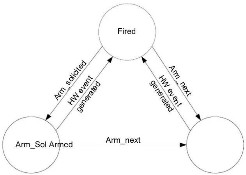
flowchart
graph TD
    A["Fired"] -->|Arm_solicited| B["Arm_Sol Armed"]
    B -->|Arm_next| C[" "]
    C -->|Arm_next| A
    A -->|HW event generated| B
    B -->|HW event generated| C
Mellanox HCAs keep track of the last index for which the user received an event. Using this index, it is guaranteed that an event is generated immediately when a request completion notification is performed and a CQE has already been reported.
In addition, HCA provides mechanism to moderate events generated by the CQ as detailed in "Completion Event Moderation" on page 142.
7.12.5 Completion Queue Update Error
CQ updates can cause errors resulting from software bugs. In particular, a CQ overrun is checked while posting a completion, and if encountered, the RQ/SQ is transferred to the appropriate error state. Hardware will deliver the auxiliary information to the software in an EQE written to the EQ.
CQ update (and error discovery) are not synchronized with WQE execution. Thus, a positive acknowledgment can be sent to the remote request, and subsequently a CQ overrun (or other error) may be detected. Hardware may not write the CQE as a result of the error, and the CQ will be transitioned to an error state as well as the RQ/SQ that caused the CQ error. To avoid these errors, software must ensure that the number of WQEs posted to a RQ/SQ does not exceed the number of entries in the CQ associated with this RQ/SQ. When multiple RQs/SQs post completions into the same CQ, this check must be cumulative.
7.12.6 Resizing a CQ
This feature enables modifying CQ size or CQEs size, driver must not modify any other field in CQC when performing this flow.
In order to resize the CQ or CQEs size, SW needs to allocate a new buffer for the CQ and pin it. Then, by submitting a MODIFY_CQ command with op_mod = 1 (Resize cq).
In this command SW needs to:
- Pass the physical pages - as it was done while opening the CQ.
- Fill below fields in the CQ context:
a. log_cq_size
b. page_offset.
c. log_page_size
Resizing Cq is enabled just if resize_cq_en =1 in QUERY_HCA_CAP command (see Section 12.3.3, "QUERY_HCA_CAP - Query Device Capabilities," on page 194).
While processing the command, the hardware will report a special CQE called Resize_Cq (CQE.opcode = 5h) to the old CQ denoting that the resizing operation has been completed. Note that this can be observed before or after the MODIFY_CQ command completes. Therefore, it is advised that the driver reserves room for one extra CQE when creating a resizeable CQ.
Once the special CQE has been observed, driver can unpin the old CQ buffer (regardless whether this happens before or after the MODIFY_CQ command completes).
When the MODIFY_CQ command completes, HW will not attempt to access the old buffer. Note that it can still contain valid CQEs; therefore, SW should still poll this buffer for CQEs until reaching the special CQE that indicates to move to the new buffer.
Note that the MODIFY_CQ command, used for resizing the CQ, cannot be nested; thus, it is not possible to issue a new MODIFY_CQ command, with the Resize CQ opcode modifier, to the same CQ before the previous one is completed.
When moving to the new CQE buffer, the index where SW should start polling at is calculated based on the consumer counter and the new CQ size. Thus, the software needs to take the log_c-q_size least significant bits of the consumer_counter and use them to reference the first CQE in the new buffer. The ownership bit is calculated similarly.
Figure 22 illustrates the resizing process.
Figure 22: CQ Resize
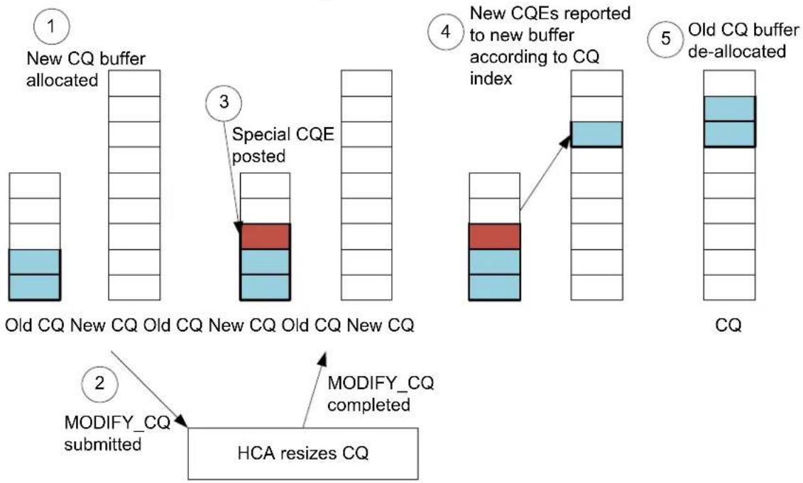
flowchart
graph TD
    A["1 New CQ buffer allocated"] --> B["2 MODIFY_CQ submitted"]
    B --> C["3 Special CQE posted"]
    C --> D["4 New CQEs reported to new buffer according to CQ index"]
    D --> E["5 Old CQ buffer de-allocated"]
    E --> F["HCA resizes CQ"]
It is recommended that when the MODIFY_CQ command ends, or before starting any new resize operation, to copy the CQEs from the old buffer to the new buffer. The process involves going through the old buffer, look for the special CQE, and then copying all prior CQEs to the new CQ omitting the special CQE. This simplifies accounting issues with the amount of CQEs that are produced by this CQ (total of at most one extra CQE, the resize special CQE, at all times).
The process of arming the CQ is unaffected by the resizing operation since the consumer/producer counters remain intact.
The format of the special resizing CQE is shown in Table 72.
Table 72 - Resize CQE Layout
| 31 | 30 | 29 | 28 | 27 | 26 | 25 | 24 | 23 | 22 | 21 | 20 | 19 | 18 | 17 | 16 | 15 | 14 | 13 | 12 | 11 | 10 | 9 | 8 | 7 | 6 | 5 | 4 | 3 | 2 | 1 | 0 | Offset |
| 00h-2Ch | ||||||||||||||||||||||||||||||||
| timestamp_h | 30h | |||||||||||||||||||||||||||||||
| timestamp_1 | 34h | |||||||||||||||||||||||||||||||
| 38h | ||||||||||||||||||||||||||||||||
| Signature | owner | 3Ch | ||||||||||||||||||||||||||||||
7.12.7 Completion With Error
Completions with error are reported to the CQ similarly to regular completions. In the case of completion with error, not all the CQE fields are valid and some of the fields have different meanings. For every WQE that completes in error, a completion with error is generated; “CQE with error” is specified by 13 or 14 value in the opcode field.
The layout of a CQE with error entry is shown in Table 73.
Table 73 - Completion with Error CQE Layout
| 31 | 30 | 29 | 28 | 27 | 26 | 25 | 24 | 23 | 22 | 21 | 20 | 19 | 18 | 17 | 16 | 15 | 14 | 13 | 12 | 11 | 10 | 9 | 8 | 7 | 6 | 5 | 4 | 3 | 2 | 1 | 0 | Offset |
| wqe_id | 00 04-1 Chh | |||||||||||||||||||||||||||||||
| 20h 24h-28h | ||||||||||||||||||||||||||||||||
| usr_index | 2Ch 30h | |||||||||||||||||||||||||||||||
| 34h | ||||||||||||||||||||||||||||||||
| vendor_error_syndrome Syndrome | Syndrome | 38h | ||||||||||||||||||||||||||||||
| S_WQE_OPCODE flow_tag | ||||||||||||||||||||||||||||||||
| wqe_counter | Signature | OPCODE | Owner | 3Ch | ||||||||||||||||||||||||||||
Field descriptions are shown in Table 74.
Table 74 - Completion with Error CQE Field Description
| Offset | Bits | Name | Description | Access |
| 15:8 | vendor_error_syndrome | Mellanox specific error syndrome. Undocumented.For further information contact Mellanox technical support. | ||
| 7:0 | syndrome | 0x1: Local_Length_Error0x4: Local_Protection_Error0x5: Work_Request_Flushed_Error0x6: Memory_Window_Bind_Error0x10: Bad_Response_Error0x11: Local_Access_Error0x12: Remote_Invalid_Request_Error0x13: Remote_Access_Error0x14: Remote_Operation_Error |
Once an RQ/SQ has transitioned to the Error state, subsequent WQEs posted to the RQ/SQ will result in reporting a completion with error (flushed) to the associated CQ.
7.12.8 Completion Queue Context (CQC)
While opening a new CQ, software should create a CQ Context object and pass it to HW using CREATE_CQ command.
The format of a CQC structure is shown in Table 75.
Table 75 - Completion Queue Context Layout
| 31 | 30 | 29 | 28 | 27 | 26 | 25 | 24 | 23 | 22 | 21 | 20 | 19 | 18 | 17 | 16 | 15 | 14 | 13 | 12 | 11 | 10 | 9 | 8 | 7 | 6 | 5 | 4 | 3 | 2 | 1 | 0 | Offset |
| status cqe_sz | cc | scqe break moderation en | oi. | st | 00h 04h | |||||||||||||||||||||||||||
| page_offset | 08h | |||||||||||||||||||||||||||||||
| log_cq_size_uar | page | 0Ch | ||||||||||||||||||||||||||||||
| cq_period cq_max_count | 10h | |||||||||||||||||||||||||||||||
| c_eqn | 14h | |||||||||||||||||||||||||||||||
| log_page_size | 18h | |||||||||||||||||||||||||||||||
| 1Ch | ||||||||||||||||||||||||||||||||
| last notified_index | 20h | |||||||||||||||||||||||||||||||
| last_solicit_index | 24h | |||||||||||||||||||||||||||||||
| consumer_counter | 28h | |||||||||||||||||||||||||||||||
| producer_counter | 2Ch | |||||||||||||||||||||||||||||||
| 30h 34h | ||||||||||||||||||||||||||||||||
| 38h-3Ch | ||||||||||||||||||||||||||||||||
| dbr_addr | ||||||||||||||||||||||||||||||||
Field descriptions are provided in Table 76.
Table 76 - Completion Queue Context Field Descriptions
| Offset | Bits Name | Description Access | ||
| 00h 31:28 status | CQ status | 0x0: OK0x9: CQ_OVERFLOW0xA: CQ_WRITE_FAILValid for the QUERY_CQ | ||
Table 76 - Completion Queue Context Field Descriptions
| Offset | Bits | Name | Description | Access |
| 10h | 27:16 | cq_period | Event Generation moderation timer in 1 usec granularity, see See Section 7.13.14, “Completion Event Moderation,” on page 142.0 - CQ moderation disabled | |
| 15:0 cq_max_count | Event Generation Moderation counter, see See Section 7.13.14, “Completion Event Moderation,” on page 142.0 - CQ moderation disabled | |||
| 14h | 7:0 | c_eqn | EQ this CQ reports completion events to. | |
| 18h | 28:24 | log_page_size | Log (base 2) of page size in units of 4KByte | |
| 20h 23:0 last_noti-fied_index | Last_notified_index. Maintained by HW.Valid for QUERY_CQ command only.This field is for debug only purpose and is subject to change. | |||
| 24h 23:0 last_solic-it_index | Solicit_producer_index. Maintained by HW.Valid for QUERY_CQ command only.This field is for debug only purpose and is subject to change. | |||
| 28h 23:0 consum-er_counter | Consumer counter. The counter is incremented for each CQE polled from the CQ.Must be 0x0 in CQ initialization Indicates last consumer counter seen by HW (valid for the QUERY_CQ command only). | |||
| 2Ch | 23:0 producer_counter | Producer Counter. The counter is incremented for each CQE that is written by the HW to the CQ.CQ overrun is reported if Producer_counter + 1 equals to Consumer_counter and a CQE needs to be added.Maintained by HW (valid for the QUERY_CQ command only) | ||
| 38h-3Ch | 64 | dbr_addr | CQ DB Record physical address | |
7.12.9 CQ to EQ Remapping
The device supports a dynamic change of the EQ to which CQ reports Completion Events. This can be done via MODIFY_CQ command (See Section 12.7.4, “MODIFY_CQ – Modify CQ Parameters,” on page 244). After successful completion of the command which remaps the EQ, the SW must call or schedule a procedure which polls the modified CQ.
7.12.10 CQE Timestamping
Each Generated CQE includes a 64 bit timestamp. This field holds a sample of the device internal timer taken when the CQE was generated. The timestamp can be used by the application to monitor execution time of I/O operations.
Note: CQEs for LRO operations coalescing TCP packets with the Timestamp Option do not carry the internal timer timestamp. This is indicated by the lro_timestamp_is_valid field in Cqe Format. See Table 67, “64B Completion Queue Entry Format Layout,” on page 117.
7.12.10.1 Conversion to Real Time
The CQE timestamp represents an internal timer using device specific frequency. To translate the timestamp into real time, the ratio is given in HCA_CAP.device_frequency field (See Table 144, "HCA Capabilities Layout," on page 196). The timestamp should be divided by the frequency to produce a value in micro-seconds.
7.12.10.2 Synchronization with Current Time
Presenting the actual time of CQE generation requires a reference point in time, synchronizing the wall-clock with the current device-clock. The current value of the device internal timer can be queried using a PCI read of the Init_segment.internal_timer_h and Init_segment.internal_timer_1 fields (See Table 7, "Initialization Segment," on page 48).
Note: Reading the internal timer using 2 PCI reads in a non-atomic manner may hit the wraparound of the 32 LSBs of the timer, making the MSBs and LSBs incompatible. Reading the 32 MSBs twice (before and after reading the LSBs) can verify a wraparound did not happen.
7.13 Events and Interrupts
HCA has multiple sources that can generate events (completion events, asynchronous events/errors). Once an event is generated internally, it can be reported to the host software via the Event Queue mechanism. The EQ is a memory-resident circular buffer used by hardware to write event cause information for consumption by the host software. Once event reporting is enabled, event cause information is written by hardware to the EQ when the event occurs. If EQ is armed, HW will subsequently generate an interrupt on the device interface (send MSI-X message or assert the pin) as configured in the EQ.
Each one of the HCA EQs can be associated with a different event handler on the host. Each Event Group can be configured to report events to one of the EQs, implementing hardware demultiplexing of the events to different event handlers. In particular, completion reports can be reported to different EQs, based on the CQ that reports the event.
In virtual environment EQs can be exported to the guest VM, and kernel driver in Guest VM will control the EQ. HCA HW enforces protection and isolation between EQs.
7.13.1 Event Queues
The EQ is an object containing the following entities:
- Event Queue Context (EQC) – The data structure describing the EQ properties that is passed to the device by SW while creating the EQ. The number of EQs supported by the hardware can be queried through the QUERY_HCA_CAP command (log_max_eq). The actual number of the EQs to be used by software (power of two) is configured at HCA initialization. EQC contains various parameters of the EQ. For more details see “Event Queue Context (EQC)” on page 139
- Event Queue – A virtually-contiguous circular buffer accessible by system software and used by hardware to post event records - Event Queue Entries (EQEs). The maximum supported EQ size is retrieved by the QUERY_HCA_CAP command (log_max_eq_sz). EQE size is 64 bytes.
- DoorBell Register associated with the EQ (see "UAR Page Format" on page 64).
7.13.2 Event Queue Buffer
An EQ is a virtually-contiguous memory buffer used by HCA to post event reports to and used by application software to poll events reports from. This buffer is allocated by the host software at EQ creation and its physical address is passed to the HCA. The memory associated with this buffer is passed to the HCA as a list of physical pages. EQ buffer must be aligned on EQE-size a boundary ^1 . EQ is shown in Figure 23.
Figure 23: Event Queue Buffer
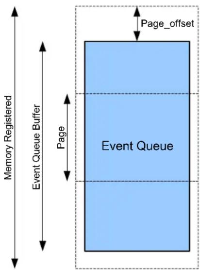
Hardware posts event records (writing EQEs) to the EQ. Upon EQEs consumptions, SW updates the EQ Doorbell register specifying the Consumer Index and change state of the EQ (for example arm it to generate interrupt on next event posted).
EQ is a virtually-contiguous circular buffer accessible by the HCA hardware and contains EQEs. The buffer is managed by Producer Counter and Consumer Counter same as CQ is managed.
Upon polling the EQ successfully (that is, a new EQE is found), software updates the Consumer Counter which is used by hardware to monitor a potential EQ overflow.
7.13.2.1 EQE Ownership
EQE ownership is defined by Owner bit in the EQE. This bit follows the logic of the Owner bit in the CQE, for details refer to “CQE Ownership” on page 123.
7.13.2.2 EQE Format
Each EQE contains enough information to associate the EQE with its CQE. The EQE layout is shown in Table 77.
Table 77 - Event Queue Entry Layout
| 31 | 30 | 29 | 28 | 27 | 26 | 25 | 24 | 23 | 22 | 21 | 20 | 19 | 18 | 17 | 16 | 15 | 14 | 13 | 12 | 11 | 10 | 9 | 8 | 7 | 6 | 5 | 4 | 3 | 2 | 1 | 0 | Offset |
| event_type event_sub_type | 00h | |||||||||||||||||||||||||||||||
| 04h-1Ch | ||||||||||||||||||||||||||||||||
| event_data | 20h-38h | |||||||||||||||||||||||||||||||
| signature | owner | 3Ch | ||||||||||||||||||||||||||||||
EQE field descriptions are shown in Table 78.
Table 78 - Event Queue Entry Field Descriptions
| Offset | Bits | Name | Description | Access |
| 00h | 23:16 | event_type | Event Type | |
| 7:0 | event_sub_type | Event Sub Type. Defined for events which have sub types, zero elsewhere. | ||
| 20h-38h | 224 | event_data | Delivers auxiliary data to handle the event. | |
| 3Ch | 15:8 | signature | Byte-wise XOR of EQE - signature protection (see See Section 9.2.4, “Completion and Event Queue Elements (CQEs and EQEs),” on page 156). EQE is valid if byte-wise XOR of entire EQE (including signature field) and the EQE index is 0xff. | |
| 0 | owner | Owner of the entry |
While draining (consuming) the EQ, software should execute the following algorithm:
While (EQ[Consumer_index].Owner == SW) {
    consume_entry(); // remove entry from the queue
    Consumer_counter++;
}
subscribe_for_event(EQ); // subscribe for event for next time
7.13.2.3 EQ DoorBell Register
EQ DoorBell register is mapped to one of the UAR (DoorBell) page. Refer to “UAR Page Format” on page 64 for details.
7.13.3 Completion Events
HCA implements CQs which are described in detail in “Software Interface” on page 62. While creating a CQ, software configures the EQ number to which this CQ will report completion events.
Further description of completion events and requests for completion events notification is provided in “Request Completion Notification” on page 124.
7.13.4 Polling on EQEs
Some applications may use EQs without generating interrupts. This is useful when the interrupt rate is too high and polling makes sense to reduce the CPU load. In this case, the EQ should be created in fired state and never be armed. Further on, an EQ will be managed by polling the EQ and updating the EQ consumer index using DoorBells (see “UAR Page Format” on page 64).
7.13.5 Sharing MSI-X/Interrupt Amongst EQs
There are cases where more than one EQ report to the same MSI-X vector or to an interrupt pin. In such cases, when servicing an interrupt, the device driver should arm all the EQs that report to the same MSI-X vector/Interrupt pin.
7.13.6 Event Queue Mapping
Each event type can be mapped to an EQ. Mapping and unmapping events to/from EQs is performed through the command interface (see “Command Reference” on page 185). Mapping completion events to EQs is performed separately for each CQ through the command interface (see “Command Reference” on page 185).
The encoding for event_type fields is shown in Table 79, "Event Type and Coding"
Table 79 - Event Type and Coding
| Family Event Description | Event Type | EQE Format | |
| Completion Events | Completion_Events | 0x0 | See Section 7.13.7, “Completion Events,” on page 136 |
| Last_WQE_Reached | 0x13 | See Section 7.13.8.1, “SQ/RQ Events,” on page 136 | |
| RQ/SQ Affiliated Asynchronous Errors | CQ_Error | 0x04 | See Section 7.13.8.2, “Completion Queue Error Event,” on page 137 |
| Unaffiliated Asynchronous Events and Errors | Internal_Error 0x08 None. | See Section 7.13.9.1, “Internal Errors,” on page 137. | |
| Port_State_Change | 0x09 | See Section 7.13.9.2, “Port State Change Event,” on page 138 | |
| Temp_Warning_Event 0x17 | |||
Table 79 - Event Type and Coding
| Family | Event Description | Event Type | EQE Format |
| HCA Inter-face | Command_Interface_Completion | 0x0A | See Section 7.13.10.1, “Command Interface Completion Event,” on page 138 |
| Page_Request | 0x0B | See Section 7.13.10.2, “Pages Request Event,” on page 139 |
The Event_Data field written to the EQ is defined in the following sections.
7.13.7 Completion Events
EQE event data is used for reporting completion events. Its layout is shown in Table 80.
Table 80 - Event_data Field - Completion Event Layout
| 31 | 30 | 29 | 28 | 27 | 26 | 25 | 24 | 23 | 22 | 21 | 20 | 19 | 18 | 17 | 16 | 15 | 14 | 13 | 12 | 11 | 10 | 9 | 8 | 7 | 6 | 5 | 4 | 3 | 2 | 1 | 0 | Offset |
| 00h-14h | ||||||||||||||||||||||||||||||||
| CQ number | 18h | |||||||||||||||||||||||||||||||
Table 81 - Event_data Field - Completion Event Field Descriptions
| Offset | Bits | Name | Description | Access |
| 18h | 23:0 | CQ number |
7.13.8 Asynchronous Events and Errors
7.13.8.1 SQ/RQ Events
The EQE event data format shown in Table 82 on page 136 is used for the following SQ/RQ related events:
- Last WQE Reached Event
Table 82 - Event_data Field - SQ/RQ Events Layout
| 31 | 30 | 29 | 28 | 27 | 26 | 25 | 24 | 23 | 22 | 21 | 20 | 19 | 18 | 17 | 16 | 15 | 14 | 13 | 12 | 11 | 10 | 9 | 8 | 7 | 6 | 5 | 4 | 3 | 2 | 1 | 0 | Offset |
| 00-10h | ||||||||||||||||||||||||||||||||
| type | 14h | |||||||||||||||||||||||||||||||
| rqn/sqn | 18h | |||||||||||||||||||||||||||||||
Table 83 - Event_data Field - SQ/RQ Events Field Descriptions
| Offset | Bits | Name | Description | Access |
| 14h 31 | :24 type | Queue type | 1: RQ2: SQ | |
| 18h 23 | :0 rqn/sqn | Indicates SQN or RQN depending on type field. |
7.13.8.2 Completion Queue Error Event
The following EQE event data format is used for reporting CQ related errors.
Table 84 - Event_data Field - Completion Queue Error Event Layout
| 31 | 30 | 29 | 28 | 27 | 26 | 25 | 24 | 23 | 22 | 21 | 20 | 19 | 18 | 17 | 16 | 15 | 14 | 13 | 12 | 11 | 10 | 9 | 8 | 7 | 6 | 5 | 4 | 3 | 2 | 1 | 0 | Offset |
| cqn | 00h | |||||||||||||||||||||||||||||||
| 04h | ||||||||||||||||||||||||||||||||
| syndrome | 08h | |||||||||||||||||||||||||||||||
| 0Ch-18h | ||||||||||||||||||||||||||||||||
Table 85 - Event_data Field - Completion Queue Error Event Field Descriptions
| Offset | Bits | Name | Description | Access |
| 00h | 23:0 | cqn | CQ number event is reported for | |
| 08h | 7:0 | syndrome | 0x1: CQ_overrun0x2: CQ_access_violation_error |
7.13.9 Unaffiliated Events and Errors
7.13.9.1 Internal Errors
Internal Errors are reported to a buffer in the HCA address space. An EQE is not generated in the case of an internal error. The device driver can either periodically poll on the buffer or register to receive an interrupt in case of an internal error.
Internal error buffer is located on the initialization segment of the HCA BAR. Interrupt can be generated regardless whether the EQ is armed. Under certain conditions, an interrupt will not be generated; it is therefore recommended to periodically poll on the Internal Error buffer.
When an error is reported, the Internal Error buffer will cause a non zero value to appear in the first DWORD of the buffer. When software detects an error indication, that is, a valid buffer, it should log the entire buffer for debug purposes.
Internal errors can be either reported by the device or detected by the device driver. Errors detected by the device can be for example: unrecognized EQE, bus error when reading from device configuration space, etc. When an error is detected, hardware reset should be performed.
7.13.9.2 Port State Change Event
The following EQE event data format is used for reporting port state change.
Table 86 - Event_data Field - Port State Change Event Layout
| 31 | 30 | 29 | 28 | 27 | 26 | 25 | 24 | 23 | 22 | 21 | 20 | 19 | 18 | 17 | 16 | 15 | 14 | 13 | 12 | 11 | 10 | 9 | 8 | 7 | 6 | 5 | 4 | 3 | 2 | 1 | 0 | Offset |
| 00h-04h | ||||||||||||||||||||||||||||||||
| port_num | 08h | |||||||||||||||||||||||||||||||
| 0Ch-18h | ||||||||||||||||||||||||||||||||
Table 87 - Event_data Field - Port State Change Event Field Descriptions
| Offset | Bits | Name | Description | Access |
| 08h | 31:28 | port_num | Port number |
The event subtype denotes whether the port new state is up or down, as shown in Table 88.
Table 88 - Port State Change Event Subtype
| Subtype Encoding | Event Subtype | Description |
| 0x1 | port state changed | port changed its state. |
| 0x4 | ||
| 0x5 |
7.13.10 HCA Interface Events
7.13.10.1 Command Interface Completion Event
Table 89 provides the EQE event data format used for reporting command completion. HCR (HCA Command Register) fields which are included in the EQE are explained in detail in “Command Interface” on page 144.
Table 89 - Event_data Field - Command interface Completion Event Layout
| 31 | 30 | 29 | 28 | 27 | 26 | 25 | 24 | 23 | 22 | 21 | 20 | 19 | 18 | 17 | 16 | 15 | 14 | 13 | 12 | 11 | 10 | 9 | 8 | 7 | 6 | 5 | 4 | 3 | 2 | 1 | 0 | Offset |
| command_completion_vector | 00h | |||||||||||||||||||||||||||||||
| 04-18h | ||||||||||||||||||||||||||||||||
Table 90 - Event_data Field - Command Interface Completion Event Field Descriptions
| Offset | Bits | Name | Description | Access |
| 00h 31:0 | command_completion_vector | Bits in this vector are set for commands completed and not yet reported by event | ||
7.13.10.2 Pages Request Event
This event is used to inform the driver that the device needs to add / release pages for one of its functions. In response to such an event, the driver will post a MANAGE_PAGES command. MANAGE_PAGES is executed once, per event, in response to Page Request Event. This command also acts as arming the Page Request Event. This implies that once Page Request Event is generated, it will not be generated again before the driver executes the MANAGE_PAGES command.
Table 91 - Pages Request Event Layout
| 31 | 30 | 29 | 28 | 27 | 26 | 25 | 24 | 23 | 22 | 21 | 20 | 19 | 18 | 17 | 16 | 15 | 14 | 13 | 12 | 11 | 10 | 9 | 8 | 7 | 6 | 5 | 4 | 3 | 2 | 1 | 0 | Offset |
| 00h | ||||||||||||||||||||||||||||||||
| num_pages | 04h | |||||||||||||||||||||||||||||||
| 08h-18h | ||||||||||||||||||||||||||||||||
Table 92 - Pages Request Event Field Descriptions
| Offset | Bits | Name | Description |
| 04h | 31:0 | num_pages | Number of missing / unneeded pages (signed number, msb indicate sign). This is just a recommendation for the driver. the actual number of pages that the driver deliver to the device is as set in the MANAGE_PAGES command. |
7.13.11 Event Queue Context (EQC)
The number of EQs supported by the HCA can be retrieved by QUERY_HCA_CAP command.
Note: EQ enumeration is per function in a multi-function device. Each one of the functions owns EQs numbered from 0x0. When an EQ is accessed, it is identified by both EQ number.
SW can create new EQE using the CREATE_EQE command. The format of the EQ Context is shown in Table 93.
Table 93 - Event Queue Context Layout
| 31 | 30 | 29 | 28 | 27 | 26 | 25 | 24 | 23 | 22 | 21 | 20 | 19 | 18 | 17 | 16 | 15 | 14 | 13 | 12 | 11 | 10 | 9 | 8 | 7 | 6 | 5 | 4 | 3 | 2 | 1 | 0 | Offset | |
| status | . | st | 00h | ||||||||||||||||||||||||||||||
| 04h | |||||||||||||||||||||||||||||||||
| page_offset | 08h | ||||||||||||||||||||||||||||||||
Table 93 - Event Queue Context Layout (Continued)
| 31 | 30 | 29 | 28 | 27 | 26 | 25 | 24 | 23 | 22 | 21 | 20 | 19 | 18 | 17 | 16 | 15 | 14 | 13 | 12 | 11 | 10 | 9 | 8 | 7 | 6 | 5 | 4 | 3 | 2 | 1 | 0 | Offset |
| log_eq_size uar | page | 0Ch | ||||||||||||||||||||||||||||||
| 10h | ||||||||||||||||||||||||||||||||
| intr | 14h | |||||||||||||||||||||||||||||||
| log_page_size | 18h | |||||||||||||||||||||||||||||||
| 1Ch-24h | ||||||||||||||||||||||||||||||||
| consumer_counter | 28h | |||||||||||||||||||||||||||||||
| producer_counter | 2Ch | |||||||||||||||||||||||||||||||
| 30h-3Ch | ||||||||||||||||||||||||||||||||
EQC fields are shown in Table 94.
Table 94 - Event Queue Context Field Descriptions
| Offset | Bits | Name | Description | Access |
| 00h 31 | :28 status | EQ status | 0x0: OK0xA: EQ_WRITE_FAILUREValid for the QUERY_EQ command only | |
| 18 | ec | Is set, all EQEs are written (collapsed) to first EQ entry | ||
| 17 oi | When set, overrun ignore is enabled. | |||
| 11:8 | st | Event delivery state machine0x9: ARMED0xA: FIREDother: reservedReserved for CREATE_EQ. | ||
| 08h | 11:6 | page_off-set | Must be 0 | |
| 0Ch | 28:24 | log_eq_size | Log (base 2) of the EQ size (in entries). | |
| 23:0 | uar_page | UAR page this EQ can be accessed through (ringing EQ DoorBells) | ||
| 14h | 7:0 | intr | MSI-X table entry index to be used to signal interrupts on this EQ.Reserved if MSI-X is not enabled in the PCI configuration header. | |
| 18h 28 | :24 log_page_size | Log (base 2) of page size in units of 4KByte | ||
| 28h 23:0 consum-er_counter | 0 | consumer-counter | Consumer counter. The counter is incremented for each EQE polled from the EQ.Must be 0x0 in EQ initialization.Indicates last consumer counter seen by HW (valid for the QUERY_EQ command only). | |
| 2Ch 23:0 produc-er_counter | 0 | producer_counter | Producer Counter. The counter is incremented for each EQE that is written by the HW to the EQ.EQ overrun is reported if Producer_counter + 1 equals to Consumer_counter and a EQE needs to be added.Maintained by HW (valid for the QUERY_EQ command only)Should be 0x0 in EQ initialization. | |
7.13.12 Hardware Interrupts
Reporting an event to the EQ can be accompanied by the generation of a hardware interrupt (generating an interrupt message on the host interface bus). Each EQ can be independently configured to assert one of the interrupt pins or generate one of the Interrupt Messages (MSI-X) on the host interface bus.
A hardware interrupt is generated if the EQ has been armed by Interrupt Handling software. While EQ is in Armed state, when an event is generated, hardware disarms the EQ and no additional interrupts are generated until the EQ is re-armed. The EQ state machine and state transitions are shown in Figure 24, "EQ State Machine".
Figure 24: EQ State Machine
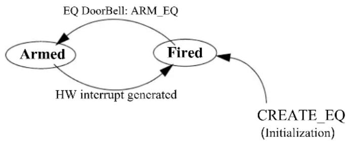
flowchart
graph TD
    A["Armed"] -->|EQ DoorBell: ARM_EQ| B["Fired"]
    B -->|HW interrupt generated| A
    B --> C["CREATE_EQ (Initialization)"]
Arming an EQ to trigger an interrupt is done by writing an EQ ARM DoorBell. Refer to “UAR Page Format” on page 64.
MSI-X is generated only if the MSI-X enable bit is set in the appropriate PCI configuration register of the device. According to the PCI specification, when MSI-X is enabled, a device is prohibited from using the INTA# pin. Therefore, EQs must be configured in accordance with the MSI-X enable bit in PCI configuration space to avoid a conflict with the PCI specification. When a device is reconfigured to a different interrupt scheme (from MSI-X to INTA# or vice versa), the EQs should be torn down and re-established with the new configuration.
7.13.13 Interrupt Moderation
The HCA supports hierarchical event delivery scheme. The completion of Work Request on WQ is reported to CQ. Multiple WQs can report completions to the same CQ. CQ that is armed to
generate event upon Work Request completion posts event to one of the EQs. Multiple CQs can report an event to same EQ. An EQ that is armed to generate interrupt upon Event report, generates interrupt by the mean configured (for example specific MSI-X message, certain pin assertion etc.). Multiple EQs can generate interrupts by the same mean (for example by generating same MSI-X message or asserting same pin).
Under high load of network traffic, it is highly desirable to moderate event reporting, hereby enabling the SW to handle multiple events upon each entry to the event handler.
HCA deploys a two-stage moderation scheme:
- Completion Event Moderation - CQs can be configured to hold off event generation (posting event report to the EQ) until certain threshold of completions are reported to that CQ (or a timeout is reached) while it is armed. Each CQ can be independently configured to operate in this mode.
- Interrupt Frequency Moderation - Frequency of Interrupts' generation can be trimmed to certain limit. Each mean of Interrupt Generation can be independently configured to trim interrupts' frequency. Each MSI-X message can be independently configured to operate in this mode.
7.13.14 Completion Event Moderation
Completion Event Moderation (CEM) delays posting of Completion Event by armed CQ until multiple completions are reported on that queue. This enables to amortize overhead of completion event handler call across multiple work completions.
CEM can be enabled for each CQ individually.
An armed CQ will generate an event when either one of the following conditions is met:
- The cq_period timer has expired and there is a pending event for this CQ (an event that would have otherwise been generated if it would not be subject to moderation). The cq_period timer restarts either upon event generation or upon completion generation, depending on the CQ.cq_period_mode (See Table 75, “Completion Queue Context Layout,” on page 129).
- The number of completions generated since the one which triggered the last event generation reached cq_max_count.
Both cq_max_count and cq_period parameters are configured in CQ that is subject to CEM.
Figure 25 illustrates event generation from CQ configured to report event after 4 completions have been posted (left) or after timeout since the last completion report expired (right).
Figure 25: Completion Event Moderation
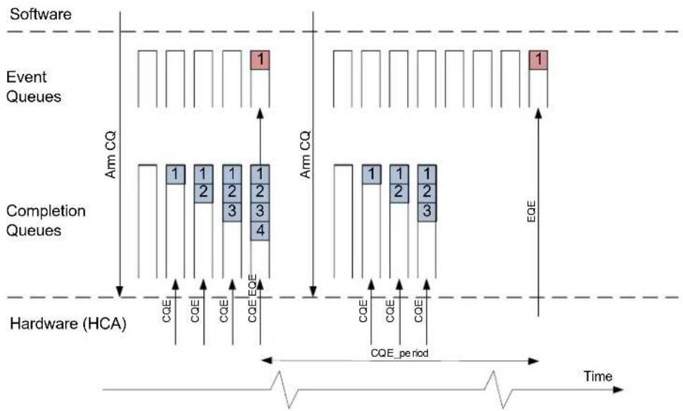
flowchart
graph TD
    A["Software"] --> B["Event Queues"]
    B --> C["Completion Queues"]
    C --> D["Hardware (HCA)"]
    D --> E["Time"]

    subgraph Software
        F1["1"] --> G1["1"]
        G1 --> H1["1"]
        H1 --> I1["1"]
        I1 --> J1["1"]
        J1 --> K1["1"]
        K1 --> L1["1"]
        L1 --> M1["1"]
        M1 --> N1["1"]
        N1 --> O1["1"]
        O1 --> P1["1"]
        P1 --> Q1["1"]
        Q1 --> R1["1"]
        R1 --> S1["1"]
        S1 --> T1["1"]
        T1 --> U1["1"]
        U1 --> V1["1"]
        V1 --> W1["1"]
        W1 --> X1["1"]
        X1 --> Y1["1"]
        Y1 --> Z1["1"]
        Z1 --> AA["EQE"]
    end

    subgraph Event Queues
        B2["Arm CQ"] --> C2["Arm CQ"]
        C2 --> D2["Arm CQ"]
        D2 --> E2["Arm CQ"]
        E2 --> F2["Arm CQ"]
        F2 --> G2["Arm CQ"]
        G2 --> H2["Arm CQ"]
        H2 --> I2["Arm CQ"]
        I2 --> J2["Arm CQ"]
        J2 --> K2["Arm CQ"]
        K2 --> L2["Arm CQ"]
        L2 --> M2["Arm CQ"]
        M2 --> N2["Arm CQ"]
        N2 --> O2["Arm CQ"]
        O2 --> P2["Arm CQ"]
        P2 --> Q2["Arm CQ"]
        Q2 --> R2["Arm CQ"]
        R2 --> S2["Arm CQ"]
        S2 --> T2["Arm CQ"]
        T2 --> U2["Arm CQ"]
        U2 --> V2["Arm CQ"]
        V2 --> W2["Arm CQ"]
        W2 --> X2["Arm CQ"]
        X2 --> Y2["Arm CQ"]
        Y2 --> Z2["Arm CQ"]
    end

    subgraph Completion Queues
        B3["Arm CQ"] --> C3["Arm CQ"]
        C3 --> D3["Arm CQ"]
        D3 --> E3["Arm CQ"]
        E3 --> F3["Arm CQ"]
        F3 --> G3["Arm CQ"]
        G3 --> H3["Arm CQ"]
        H3 --> I3["Arm CQ"]
        I3 --> J3["Arm CQ"]
        J3 --> K3["Arm CQ"]
        K3 --> L3["Arm CQ"]
        L3 --> M3["Arm CQ"]
        M3 --> N3["Arm CQ"]
        N3 --> O3["Arm CQ"]
        O3 --> P3["Arm CQ"]
        P3 --> Q3["Arm CQ"]
        Q3 --> R3["Arm CQ"]
        R3 --> S3["Arm CQ"]
        S3 --> T3["Arm CQ"]
        T3 --> U3["Arm CQ"]
        U3 --> V3["Arm CQ"]
        V3 --> W3["Arm CQ"]
        W3 --> X3["Arm CQ"]
        X3 --> Y3["Arm CQ"]
        Y3 --> Z3["Arm CQ"]
    end

    subgraph Hardware (HCA)
        D4["CQE"] --> E4["CQE Period 0-5"]
    end

    style Software fill:#f9f,stroke:#333
    style Event Queues fill:#ccf,stroke:#333
    style Completion Queues fill:#cfc,stroke:#333
    style Hardware (HCA) fill:#fcc,stroke:#333
    style Hardware (HCA) fill:#ffc,stroke:#333
    style Hardware (HCA) fill:#fcc,stroke:#333
    style Hardware (HCA) fill:#fcc,stroke:#333
    style Hardware (HCA) fill:#fcc,stroke:#333
    style Hardware (HCA) fill:#fcc,stroke:#333
    style Hardware (HCA) fill:#fcc,stroke:#333
    style Hardware (HCA) fill:#fcc,stroke:#333
    style Hardware (HCA) Fill Time
    note right of A: "Arm CQ"
    note left of A: "CQE period"
    note right of A: "Time"
CQ is transferred to fired state after event has been reported.
CEM is expected to be deployed on CQs that consolidate completion reports from multiple independent and concurrently-operating WQs.
For CQs with CQ.scqe_break_moderation_en==1, solicited CQE (CQE.SE flag is enabled) breaks moderation and generates an immediate EQE.
Note that this feature is supported if HCA_CAP.scqe_break_moderation is enabled.
7.13.15 Interrupt Frequency Moderation
Interrupt Frequency Moderation (IFM) trims the frequency of interrupt assertion on the chip interface.
IFM is implemented on each interrupt (pin or message) and it assures that this interrupt is not asserted at a rate higher than one configured. Each interrupt message/pin can be independently configured to trim interrupt frequency; this property is configured in Interrupt Context Table. After interrupt request is generated on IFM-enabled interrupt, HW checks the value of interrupt-associated timer. If this timer value is zero, interrupt is generated on the chip interface, timer is re-loaded with int_period field of the respective entry in Interrupt Context Table and timer starts count-down. If timer value was not zero when interrupt request was generated, the interrupt generation on the chip interface will be delayed until timer is expired. Every time interrupt is fired (generated) on chip interface, the timer is re-loaded and starts count-down.
This mechanism assures that interrupts are not generated more frequently than int_period time ticks apart. However, if interrupt has not been generated for a long time, the interrupt request will result in immediate generation of interrupt on chip interface. Figure 26 illustrates IFM mechanism.
Figure 26: Interrupt Frequency Moderation
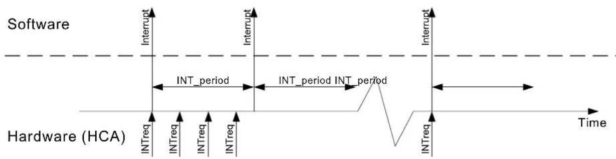
flowchart
graph LR
    A["Interrupt"] --> B["INT_period"]
    B --> C["INT_period INT_period"]
    C --> D["Interrupt"]
    E["INTreq"] --> F["INTreq"]
    F --> G["INTreq"]
    G --> H["INTreq"]
    H --> I["INTreq"]
    I --> J["INTreq"]
    J --> K["INTreq"]
    K --> L["INTreq"]
    L --> M["INTreq"]
    M --> N["INTreq"]
    N --> O["INTreq"]
    O --> P["INTreq"]
    P --> Q["INTreq"]
    Q --> R["INTreq"]
    R --> S["INTreq"]
    S --> T["INTreq"]
    T --> U["INTreq"]
    U --> V["INTreq"]
    V --> W["INTreq"]
    W --> X["INTreq"]
    X --> Y["INTreq"]
    Y --> Z["INTreq"]
    Z --> AA["INTreq"]
    AA --> AB["INTreq"]
    AB --> AC["INTreq"]
    AC --> AD["INTreq"]
    AD --> AE["INTreq"]
    AE --> AF["INTreq"]
    AF --> AG["INTreq"]
    AG --> AH["INTreq"]
    AH --> AI["INTreq"]
    AI --> AJ["INTreq"]
    AJ --> AK["INTreq"]
    AK --> AL["INTreq"]
    AL --> AM["INTreq"]
    AM --> AN["INTreq"]
    AN --> AO["INTreq"]
    AO --> AP["INTreq"]
    AP --> AQ["INTreq"]
    AQ --> AR["INTreq"]
    AR --> AS["INTreq"]
    AS --> AT["INTreq"]
    AT --> AU["INTreq"]
    AU --> AV["INTreq"]
    AV --> AW["INTreq"]
    AW --> AX["INTreq"]
    AX --> AY["INTreq"]
Interrupt Frequency Moderation can always be deployed to assure that interrupts are not generated by the HCA at excessive rate. Interrupt moderation is configured through the CONFIG_INT_MODERATION command.
7.14 Command Interface
The HCA command interface is used for:
- configuring the HCA
• the handshake between hardware and system software - handling (querying, configuring, modifying) HCA objects
The HCA is configured using the command queues. Each function has its own command queues to get commands from its HCA driver. A detailed reference for the syntax of the command interface commands is provided in Chapter 12, “Command Reference” (page 185).
7.14.1 HCA Command Queue
The command queue is the transport that is used to pass commands to the HCA.
The command queue is a buffer on fixed-size entries. Each entry can contain one command queue entry. The number of entries and the entry stride can be retrieved from the initialization segment of the HCA Bar. See Table 7, "Initialization Segment".
The command queue resides in physically contiguous 4KB memory chunk aligned on its size. The physical address of this memory chunk is configured by SW to the initialization segment.
The command queue is a directional way to send commands. SW will put a command request in it and will receive a command response. When posting an entry to the command queue, SW will ring the command DoorBell vector in the initialization segment by writing to this vector with the respective (to the newly posted command) bit set. If EQ is set and mapped to this command queue, SW will be informed on command completion by EQE.
SW can execute a single write to the DoorBell vector for multiple commands by setting multiple bits in the DoorBell vector.
Hardware Function may execute and complete the commands in an out-of-order manner. Once a command is completed, the ownership bit of the command is updated and the event is generated.
It is SW's responsibility to ensure successful generation of this event. Consequently, if no room is left in EQ buffer, the command should not be sent until the EQ consumer index has been updated (using EQ doorbell).
The event data includes the command completion vector. Bits in this vector are set for commands completed after the former event.
As an alternative to waiting for events, SW can poll the ownership bit in the command to understand when the command is completed.
Before EQ was generated, SW cannot wait for events to understand the status of commands. Once EQ is created and mapped, as well as mapped for command completion events on the command queue, SW can wait for events.
Note that the CREATE_EQ command that maps EQ to the command queue must be posted to the command queue while it is empty and no other command should be posted.
Table 95, “Command Queue Entry Layout,” on page 145 shows the layout of the command. Note that status bit and all reserved fields should be set to zero by SW when posting the command.
When a command request is carried by a command queue entry, the first 16 bytes of the command reside as inline data in the command_input_inline_data field. The rest of the command will be in the input mailbox. For the command response, the first 16 bytes will reside in the command_output_inline_data. The rest of the command response will be in the output mailbox.
Table 95 - Command Queue Entry Layout
| 31 | 30 | 29 | 28 | 27 | 26 | 25 | 24 | 23 | 22 | 21 | 20 | 19 | 18 | 17 | 16 | 15 | 14 | 13 | 12 | 11 | 10 | 9 | 8 | 7 | 6 | 5 | 4 | 3 | 2 | 1 | 0 | Offset |
| type | 0h | |||||||||||||||||||||||||||||||
| input_length | 04h | |||||||||||||||||||||||||||||||
| input mailbox pointer[63:32] | 08h | |||||||||||||||||||||||||||||||
| input mailbox pointer[31:9] | 0Ch | |||||||||||||||||||||||||||||||
| command_input_inline_data | 10h-1Ch | |||||||||||||||||||||||||||||||
| command_output_inline_data | 20h-2Ch | |||||||||||||||||||||||||||||||
| output mailbox pointer[63:32] | 30h | |||||||||||||||||||||||||||||||
| output mailbox pointer[31:9] | 34h | |||||||||||||||||||||||||||||||
| output_length | 38h | |||||||||||||||||||||||||||||||
| token signature status | ownership | 3Ch | ||||||||||||||||||||||||||||||
Table 96 - Command Queue Entry Field Descriptions
| Offset Bits Name | Description Access | |||
| 00h | 31:24 | type | Type of transport that carries the command 0x7: PCIe_cmd_if_transport | |
| 04h | 31:0 | input_length | Input command length in bytes | |
| 08h 31 | :0 input mail-box pointer[63:32] | Pointer to input mailbox | ||
| 0Ch 31 | :9 input mail-box pointer[31:9] | |||
| 10h-1Ch | 128 command_in-put_inline-data | The first 16 bytes of the command input | ||
| 20h-2Ch | 128 command_output_inline_data | The first 16 bytes of the command output | ||
| 30h 31 | :0 output mail-box pointer[63:32] | Pointer to output mailbox | ||
| 34h 31 | :9 output mail-box pointer[31:9] | |||
| 38h | 31:0 | output_length | Output command length in bytes | |
| Offset | Bits | Name | Description | Access |
| 3Ch | 31:24 | token | Token of the command. Should have the same value in the command and the mailbox blocks. | |
| 23:16 | signature | 8 bit signature of the command queue entry, Does not include the mail-box. | ||
| 7:1 status Command delivery status0x0 - no errors0x1 - signature error0x2 - token error0x3 - bad block number0x4 - bad output pointer. pointer not aligned to mailbox size0x5 - bad input pointer. pointer not aligned to mailbox size0x6 - internal error0x7 - input len error. input length less than 0x80x8 - output len error. output length less than 0x80x9 - reserved not zero0x10 - bad command typeSW should set this field to 0 when posting the command. | ||||
| 0 | ownership | SW should set to 1 when posting the command. HW will change to zero to move ownership bit to SW. | ||
For commands posting, notification on completion, and events generation see Section 11.1, “Initialization,” on page 365.
7.14.1.1 Mailbox Format
Input and output mailboxes are shown in Table 97, “Command Interface Mailbox Layout,” on page 147. If the mailbox data is larger than the size of the mailbox-data field, the first part of the data will be in the first mailbox block, the second part in the second block etc.
Table 97 - Command Interface Mailbox Layout
| 31 | 30 | 29 | 28 | 27 | 26 | 25 | 24 | 23 | 22 | 21 | 20 | 19 | 18 | 17 | 16 | 15 | 14 | 13 | 12 | 11 | 10 | 9 | 8 | 7 | 6 | 5 | 4 | 3 | 2 | 1 | 0 | Offset |
| mailbox data | 00h-1FCh | |||||||||||||||||||||||||||||||
| 200h-22Ch | ||||||||||||||||||||||||||||||||
| next_pointer[63:32] | 230h | |||||||||||||||||||||||||||||||
| next_pointer[31:10] | 234h | |||||||||||||||||||||||||||||||
| block number | 238h | |||||||||||||||||||||||||||||||
| token | ctrl_signature | signature | 23Ch | |||||||||||||||||||||||||||||
Table 98 - Command Interface Mailbox Field Descriptions
| Offset | Bits Name Description Access | |||
| 00h-1FCh | 4096 | mailbox data Data in the | mailbox | |
| 230h | 31:0 | next_pointer[63:32] | Pointer to the next mailbox page (if needed). If no additional block is needed, the pointer should be 0. | |
| 234h | 31:10 | next_pointer[31:10] | Pointer to the next mailbox page (if needed). If no additional block is needed, the pointer should be 0. | |
| 238h | 31:0 | block number | Sequence number of the block. Starting by 0 and increment for each block on the linked list of blocks. | |
| 23Ch | 23:16 | token | Token of the command. Should have the same value in the command and the mailbox blocks. | |
| 15:8 | ctrl_signature | Signature dwords 1D0h-1FCh result of bytewise XOR of all those DWORDs including the ctrl_signature should result in 0xFF (while the signature byte is considered as 0). | ||
| 7:0 | signature | Signature of the current mailbox page. bytewise XOR of all bytes of the page, including the reserved fields and the signature fields should result in 0xFF. | ||
7.14.1.1.1 Calculating Mailbox Signatures
Mailbox signatures are calculated for each mailbox block independently. Calculation is done in the following way:
- update all fields of the mailbox block with their values
- write '0' to the ctrl_signature and the signature fields
- calculate bytewise-xor of the ctrl part (bytes 1C0h - 1FFh)
- invert the result and write it to the ctrl_signature field
- re-calculate bytewise-xor of the whole mailbox block
- invert the result and write it to the signature field
- before posting of command, the signatures of the command queue entry and the input mailbox should be calculated. In addition, the ctrl_signature of the output mailbox blocks should be calculated. This is to protect the output mailbox pointers and token fields.
7.14.1.2 Command Data Layout
The layout of the input command is shown in Table 99, “Command Input Data Layout,” on page 149.
Table 99 - Command Input Data Layout
| 31 | 30 | 29 | 28 | 27 | 26 | 25 | 24 | 23 | 22 | 21 | 20 | 19 | 18 | 17 | 16 | 15 | 14 | 13 | 12 | 11 | 10 | 9 | 8 | 7 | 6 | 5 | 4 | 3 | 2 | 1 | 0 | Offset | ||||||
| opcode | 00h | |||||||||||||||||||||||||||||||||||||
| op_mod | 04h | |||||||||||||||||||||||||||||||||||||
| command[0] | 08h | |||||||||||||||||||||||||||||||||||||
| command[1] | 0Ch | |||||||||||||||||||||||||||||||||||||
| ... | ... | |||||||||||||||||||||||||||||||||||||
Table 100 - Command Input Data Field Descriptions
| Offset | Bits Name Description Access | |||
| 00h 31:16 | opcode | |||
| 04h | 15:0 | op_mod | Opcode modifier, if there is no description, then op_mod must be 0. | |
| 08h-... | 31:0 command[...] | |||
The layout of the output command is shown in Table 101, “Command Output Data Layout,” on page 149.
Table 101 - Command Output Data Layout
| 31 | 30 | 29 | 28 | 27 | 26 | 25 | 24 | 23 | 22 | 21 | 20 | 19 | 18 | 17 | 16 | 15 | 14 | 13 | 12 | 11 | 10 | 98 | 76 | 54 | 32 | 10 | Offset | |||||
| status | 00h | |||||||||||||||||||||||||||||||
| syndrome | 004h | |||||||||||||||||||||||||||||||
| command output | 08h | |||||||||||||||||||||||||||||||
Table 102 - Command Output Data Field Descriptions
| Offset | Bits Name Description Access | |||
| 00h 31:24 status | ||||
| 04h | 31:0 | syndrome | Syndrome on the command. Valid only if status = 0x0. | |
| 08h | 31:0 | command output | Command output. Valid only if status = 0x0. | |
8 Initialization and Teardown
8.1 Initialization
Adapter initialization is performed in the following three stages:
- Device boot from attached NVMEM (Flash) – see “Stage 1 - Device Boot From Attached NVMEM” on page 150.
- PCI device initialization is performed via boot software enumeration. In this stage the device is discovered by the PCI enumeration software, and its memory BAR registers are programmed to enable the CPU access to the adapter's configuration space. The device may include multiple functions. See “Stage 2 - PCI Device Initialization via Boot Software Enumeration” on page 150.
- Embedded switch or Physical port initialization.
- Drivers initialization on each of the functions - see "IICA Driver Start-up" on page 151.
8.1.1 Stage 1 - Device Boot From Attached NVMEM
After the HW reset signal is de-asserted, the device boots by reading the firmware image (configuration) from the attached Flash device. Each sector of the Flash is CRC-protected, and the device validates the signature of the sector read. If signature validation fails, the device initializes itself as a “Flash programming device”. Thus, once the host boots, the firmware image can be downloaded to the attached Flash device.
Once the firmware image has been loaded to the device's internal memory and component initialization has completed, the device is ready to respond to PCI enumeration. Prior to this condition, the device responds with the 'configuration retry status' completion status to type0 configuration cycles targeting the device.
8.1.2 Stage 2 - PCI Device Initialization via Boot Software Enumeration
In this stage, the adapter device responds to configuration cycles allowing PCI enumeration software to discover the device. The device may contain multiple functions. Those functions may be Physical Functions (PFs) or Virtual Functions (VFs). Each function has a single BAR on the PCI address space.
The device can support the following PCI capabilities. The actual capabilities supported can be retrieved from the PCI configuration header. For more details, see the PCI Express Base Specifications.
• p c i e
• m s i x
• s r i o v
• ari
- power management
• vpd
- serial number
- advanced error reporting
After PCI fabric initialization is completed (for example, BAR registers assigned), the HCA driver initializes and configures the device as described below.
Note: The driver should ensure that the Bus Master bit in the Command Register is set in the PCI configuration header of the HCA prior to executing further commands on the command interface.
8.2 HCA Driver Start-up
After PCI Express fabric enumeration is completed and software has assigned PCI memory space, the HCA is assigned with a single bar called “HCA BAR”, device bring-up can start. The device is initialized by executing the following sequence.
- Read the initialization segment from offset 0 of the HCA BAR, to retrieve the versions of the firmware and the command interface. The driver must match the command interface revision number. The format of the initialization segment is in Table 7, “Initialization Segment,” on page 48
- Write the physical location of the command queues to the initialization segment. If using 32-bit writes, write the most significant word first. The nic_interface field is part of the least significant word and must be set to zero (Full NIC/HCA driver), as are the log_cmdq_size and log_cmdq_stride fields.
- Read the initializing field from the initialization segment. Repeat until it is cleared (INIT_SEGMENT.initializing become 0).
- Execute ENABLE_HCA command.
- Execute QUERY_ISS1 command. See "ISS1 - Interface Step Sequence ID" on page 62.
- Execute SET_ISSI command.
- Execute QUERY_PAGES to understand the HCA need for boot pages.
- Execute MANAGE_PAGES to provide the HCA with all required boot pages, The driver is allowed to give the sum of boot pages and num_init_pages.
- Execute QUERY_HCA_CAP to retrieve the device capabilities limits.
- Execute SET_HCA_CAP to modify system capabilities.
- Execute QUERY_PAGES to understand the HCA need for initial pages for executing commands. If init_pages is 0, no need to do the MANAGE_PAGES stage.
- Execute MANAGE_PAGES to provide the HCA with all require init-pages. This can be done by multiple MANAGE_PAGES commands.
- Execute INIT_HCA command to initialize the HCA.
- Execute SET_DRIVER_VERSION command (only in case HCA_CAP.driver_version==1). See Section 12.3.12, "SET_DRIVER_VERSION," on page 218.
- Execute the “CREATE_EQ – Create EQ” on page 234 command to create EQ. Map PAGE_REQUEST event to it.
- Execute QUERY_VPORT_STATE command to get vport state.
- For Ethernet, execute QUERY_VPORT_CONTEXT command to get permanent MAC address. (See Section 14.1.7, “Virtual NIC Start-Up,” on page 409).
- Execute MODIFY_VPORT_CONTEXT command to set current MAC address. (See Section 14.1.7, "Virtual NIC Start-Up," on page 409).
The commands are explained in detail in Chapter 12, “Command Reference” on page 185.
8.3 HCA Driver Teardown and Re-initialization
Each Function of the HCA can be individually and independently shut down (and re-initialized/restarted later on) by software. When a PF is shut down, its VFs are also shut down. This operation is performed while the system shuts down gracefully, when PCI bus re-enumeration and memory re-allocation is required or when user decided to right-click-disable network device. In this case, software should perform the following steps:
- Stop all operations of function being shut down and destroy all resources.
- Unmap the EQ that the PAGE request events are mapped to and destroy the EQ.
- Execute the TEARDOWN_HCA command to close the HCA.
- Call MANAGE_PAGES in loop till all pages are reclaimed.
- Execute DISABLE_HCA command.
After TEARDOWN_HCA is acknowledged by the hardware, HCA will not attempt to access PCI on behalf of that ICM.
8.4 Physical port Initialization and Configuration
The physical port managed, configured and controlled using port control registers, see Table 104, "Ports Register Summary," on page 161.
Part 2: Advanced Mellanox Adapter Features
9 Data Integrity
The device implements advanced techniques to assure data integrity for both hardware and software:
- Hardware level - the device implements all mandatory and optional data integrity checks on its physical interfaces (network interface, PCIe interface). Hardware assures smooth recovery in an unlikely event of internal data corruption (SER or alike).
- Software level - the device validates data integrity of memory-resident control objects and work queues, reducing probability of bogus I/O operation caused by software that strolled through control objects and corrupted them.
9.1 Hardware-level Data Integrity
The device is designed to assure soft error SDC MTBF of 50,000 years. The device also implements end-to-end data protection on its data path.
Error recovery and correction error logic is designed to correct internal errors.
Atomic and other certain operations are instantiated multiple times in hardware and an error indication is set if there is no consensus between them.
Data integrity errors are detected and reported to the software as specified in Table 103.
Table 103 - Data Integrity Detection and Reporting
| Interface / Component | Method of Detection | Method of Reporting |
| PCI Express Inter-face | LCRC, ECRC and Advanced Error Reporting header. | Per PCI Express specification |
| Network Interface ICRC | VCRC, Ethernet CRC, FC CRC | As specified in respective network standards. A packet that experienced CRC error is discarded and carefully counted in respective bin. |
| Internal operation errors | Majority vote | Internal Error counter bumped. |
| Flash Contents | 16-bit CRC | The device boots in non-operational mode (EEPROM burner mode), or the device boots normally but fails upon the RUN_FW command and reports the problem. |
| SER Exposed Internal Logic (All Memory Arrays) | ECC, CRC Respective | counter bumped up |
| SER Exposed Internal Logic (internal HW registers) | ECC Also known as F | FSER.Causes immediate disabling of PCI interface. Reset is required in order to continue operation. |
Data integrity checks/generation overlap between different domains (for example, “check integrity upon data receive” and “generate ECC before store”).
The PCI-Express bus supports data integrity checks. The data integrity checks on the PCI-Express interface log the address of the access that caused the failure. The address can then be reported to software and can be associated with a transaction by the application running on top of the HCA device. Subsequently graceful recovery can be done.
9.2 Software-level Data Integrity - Control Objects' Consistency Checks
The device implements basic protection against buggy SW that can corrupt its control structures and objects.
9.2.1 Device Configuration and Control Communication
- As a first step in protection, the device does not expose its register space for writing. The control communication with the device is implemented via a Command queue mechanism. See "HCA Command Queue" on page 144 for more details. Software writes a control message to a Command queue in system memory.
- Software seals the Command with an 8-bit XOR signature.
- If the command includes an input mailbox, the mailbox is also protected by the command signature. This include all reserved fields of the mailbox.
- Software informs the device that such command was posted by writing to the “command DoorBell vector” register in the device. (This is one of the rare writes that is NOT ignored by the device).
- The device reads the command from the Command Queue, validates the signature, and will only proceed if the validation passed.
- The device writes the output mailbox, updates the status of the command, regenerates the signature such that it will include the updated status and the output mailbox (input mailbox is not included).
9.2.2 Memory-resident Control Objects
Control structures required for the HCA operation (context tables, translation tables etc.) are kept in the host memory allocated for the device. This memory is called Interconnect Context Memory (ICM) and it is essentially a part of the HCA hardware. See Section 5.1, “Interconnect Context Memory,” on page 52 for details. Host software should never access memory allocated for the HCA control objects.
Since the HCA cannot prevent corruption of its ICM memory located in host memory, it implements basic consistency checks.
Consistency checks are implemented by attaching a signature to every control object. This signature is generated by the HCA every time it writes an object to memory and this signature is validated every time it reads the object from memory. If the consistency check fails, the device treats this object as “not present” (invalid) and generates an event/interrupt to the host software, indicating address of memory location that was corrupted. If a context object corruption is detected during an I/O operation, it will complete same way as if the corrupted object was invalid or missing. Other I/O operations will not be affected and execution will proceed.
In order to generate the event notifying of the corruption of a control object, the HCA must read from ICM memory various control objects for the event queue designated for these reports. If one of these objects is corrupted, it is impossible for the HCA to generate the event. In this case, HCA will issue “CONTROL OBJECT CORRUPTION REPORT FAILURE” interrupt; status
information with object address and object ID that caused this failure can be read by software from “control corruption” register.
We cannot guarantee that HCA can always handle ICM corruption gracefully. For instance, failure to post EQE reporting object corruption is considered to be a fatal error and HCA will halt execution - all committed data transfers (PCI and network) will be completed, but no new operation will start and the HCA will halt awaiting for hardware reset. The mean of this special interrupt (pin, MSIX vector etc.) is configured at HCA initialization step as described in “Initialization and Teardown” on page 365.
9.2.3 Work Queues Elements Signature
Work Queue Elements (WQEs) undergo syntax/consistency checks as described in the “Work Request (WQE) Formats” on page 75. These checks assure that operation specified in the WQE is consistent with queue this WQE is posted on. In addition to these syntax checks, the HCA can check a signature written on each WQE.
The WQE signature is generated by software posting the WQE. In addition to the WQE itself, the SQ/RQ number of the queue the WQE is posted to, and the index of that particular WQE are considered in the signature. Send WQE signature is within the control segment. Receive WQE signature is in a different, additional segment.
Signatures must be generated by the software posting Work Request, which consumes CPU cycles. However, in many cases posting Work Request is a performance-critical operation. The device provides an option to skip consistency checks, thereby avoiding this software overhead on post operation. Each WQ can be independently configured to enforce WQE signature validation software.
9.2.4 Completion and Event Queue Elements (CQEs and EQEs)
The HCA inserts a signature to Completion Queue Elements (CQEs) and Event Queue Elements (EQEs) when writing them. While polling the element from the queue, consumer can check the signature.
Figure 27 illustrates schematically CQ and EQ containing signature, showing valid and invalid entries in the queue. Detailed CQE format is discussed in Section 7.12.1.1, "CQE Format," on page 117 and EQE in Section 7.13.2.2, "EQE Format," on page 134.
Figure 27: Completion and Event Queues
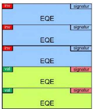
Completion QueueEvent Queue
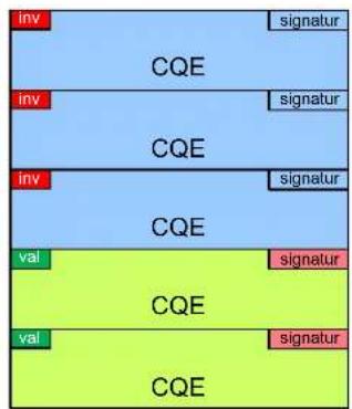
Hardware always generates signatures for CQEs and EQEs. Validation of these signatures is under software control. Consumer can save CPU cycles by ignoring signature field, thereby accelerating CQ or EQ poll function calls.
10 Address Translation and Protection Enhancements
10.1 Lightweight Memory Registration
Lightweight memory registration enables the creation of virtually-contiguous address spaces out of disjoint (non-contiguous) chunks of memory region(s) already registered with the HCA.
With the adapter device, this is done with a User Mode Memory Registration (UMR) Work Request posted to a SQ. This is the “right way” to execute lightweight memory registration on the device. UMR is a non-privileged operation enabling creation of a virtually contiguous memory region on byte granularity. This is the fastest and recommended way to execute light memory registration on the device.
UMR Work Request is also used for invalidation of memory region/window.
UMR is described below in "User-Mode Memory Registration (UMR)" on page 158.
10.1.1 User-Mode Memory Registration (UMR)
UMR is a mechanism to alter the address translation properties of MKeys by posting Work Requests on SQs. The key advantage of this mechanism versus prior fast registration implementations is that this operation can be executed by non-privileged software and the granularity (size and alignment) of memory sections specified by the KLM entries are not constrained (in contrast to page or block granularity previously required).
UMR can also alter some of the original MKey fields. MKey fields to update are marked in the MKeyCtx mask bit (in the UMR control segment) and their new values are taken from the MKeyCtx section in the UMR WQE.
Not all MKey fields can be changed by a UMR request. HW will block changing fields that should not be changed. For the list of fields that can be changed, see Table 33, “UMR Control Segment Fields,” on page 79.
UMR can be executed on a memory region only if the umr_en bit in Mkey Context is set.
An indirect memory key, when initially created, has no virtual to physical mapping and cannot be used until it is mapped to physical addresses by executing a UMR request on one of the SQs.
UMR uses the MKey index as an argument and fills in its corresponding memory translation table entries from a list of virtual buffers specified in the UMR request.
UMR specifies access rights for the Mkey being configured. If HCA_CAP.imaicl=0, in the course of address translation, HW validates that the access rights in an indirect MKey do not exceed the access rights of the MKey pointed by it. An access right (e.g, remote write) is granted if, and only if, it is allowed by all MKeys processed in the course of this address translation. Thus, bogus programming of access rights to an indirect MKey is discovered during a memory access that uses this key and will be reported as a memory access error and not as UMR programming error.
If HCA_CAP.imaicl=1 however, an MKey accessed through an indirect MKey need not have remote access rights. This allows, for instance, to implement Memory Window (implemented by an indirect mkey) with remote access bound to a Memory Region (implemented by a direct mkey) with no remote access rights. Kernel protocol drivers can also use this ability to register indirect MKeys with remote access on top of the reserved LKey.
The new translation given by a UMR request takes effect prior to the execution of the next command on the same WQ (this WQE should be marked with small-fence), thereby enabling the posting of a UMR followed by a WQE using the same key in a single operation.
UMR requests of a single indirect MKey can be performed repeatedly. Each UMR request remaps the MKey's translation entries. Unlike previous implementations, software does not need to handle the synchronization of the HCA's cache. Changing the variant field of the MKey can be done by software for security purposes, but no cache flush or other synchronization operations are required for the repeated use of same MKey.
10.1.1.1 UMR Work Request Operation
UMR Work Request modifies a variant part of the MKey and changes its MTT entries, loading a new list of buffers that will be used for address translation. For invalidation by UMR, however, no new buffer translation entries are loaded.
Hardware executes the following steps when executing a UMR Work Request:
- Checks whether the MKey is valid
- Checks whether the MKey is free
- Checks whether the PD of the SQ matches the PD of the MKey
- Checks that the MKC.umr_en=1
- Checks that buffers' list specified by the WQE does not exceed the memory allocated for that MKey
- If all checks are successful, buffers' list specified by WQE is copied to MTT and xt fields are updated
- Reports completion on the WQE. If some of the checks failed, completion with error is reported along with advised action to be applied on the programmer.
The protection checks are executed at every stage, either when an indirect MKey or a direct MKey is used.
Part 3: Command Reference and Registers
11 Command Registers
11.1 Network Ports Registers
This section lists the various registers that uses to query and modify the physical ports parameters and capabilities. The table below summarize the port control registers.
Table 104 - Ports Register Summary
| Register Name | Register ID (hex) | Function | Applicable to | Protocol | Reference | ||||
| Query | Write | Event | Switch | HCA | Ethernet | ||||
| PMTU | 0x5003 | v | v | v | v | v | v | See Table 105, “PMTU - Port MTU Register Layout,” on page 161 | |
| PTYS | 0x5004 | v | v | v | v | v | See Table 107, “PTYS - Port Type and Speed Register Fields,” on page 162 | ||
| PAOS | 0x5006 | v | v | v | See Table 109, “PAOS - Ports Administrative and Operational Status Register Layout,” on page 163 | ||||
| PFCC | 0x5007 | v | v | v | See Table 111, “PFCC - Ports Flow Control Configuration Register Layout,” on page 164 | ||||
| PPCNT | 0x5008 | v | v | See Table 113, “PPCNT - Ports Performance Counters Register Layout,” on page 166 | |||||
11.1.1 PMTU - Port MTU Register
The PMTU register configures and reports the port MTU.
Table 105 - PMTU - Port MTU Register Layout
| 31 | 30 | 29 | 28 | 27 | 26 | 25 | 24 | 23 | 22 | 21 | 20 | 19 | 18 | 17 | 16 | 15 | 14 | 13 | 12 | 11 | 10 | 9 | 8 | 7 | 6 | 5 | 4 | 3 | 2 | 1 | 0 | Offset |
| local_port | 00h | |||||||||||||||||||||||||||||||
| max_mtu | 04h | |||||||||||||||||||||||||||||||
| admin_mtu | 08h | |||||||||||||||||||||||||||||||
| oper_mtu | 0Ch | |||||||||||||||||||||||||||||||
Table 106 - PMTU - Port MTU Register Fields
| Offset | Bits | Name | Description | Access |
| 00h | 23:16 | local_port | Local port number. | Index |
| 04h | 31:16 | max_mtu | Maximum MTU supported on the port (Read Only). | RO |
| 08h | 31:16 | admin_mtu | Administratively configured MTU on the port. Must be smaller or equal to max_mtu. | RW |
Table 106 - PMTU - Port MTU Register Fields
| Offset | Bits | Name | Description | Access |
| 0Ch | 31:16 | oper_mtu | Operational MTU. This is the actual MTU configured on the ports. Packets exceeding this size will be dropped. | RO |
11.1.2 PTYS - Port Type and Speed Register
The PTYS register configures and reports the port type speed.
Note: Setting the admin fields of this register shall only take effect during link training and negotiation. When set while the link is up, the changes will not take effect unless the port goes back to training and negotiation state (during transition from down to up state). Software can force training by disabling and enabling the port.
Table 107 - PTYS - Port Type and Speed Register Fields
| 31 | 30 | 29 | 28 | 27 | 26 | 25 | 24 | 23 | 22 | 21 | 20 | 19 | 18 | 17 | 16 | 15 | 14 | 13 | 12 | 11 | 10 | 9 | 8 | 7 | 6 | 5 | 4 | 3 | 2 | 1 | 0 | Offset |
| local_port | proto_mask | 00h | ||||||||||||||||||||||||||||||
| 04h 08h | ||||||||||||||||||||||||||||||||
| 0Ch | ||||||||||||||||||||||||||||||||
| eth_proto_capability | 10h 14h | |||||||||||||||||||||||||||||||
| 18h 1Ch 20h | ||||||||||||||||||||||||||||||||
| eth_proto_admin | 24h 28h 2Ch 30h 34-3Ch | |||||||||||||||||||||||||||||||
Table 108 - PTYS - Port Type and Speed Register Fields
| Offset | Bits Name | Description Access | ||
| 00h 31 reserved | ||||
| 23:16 | local_port | Local port number | ||
| 2:0 | proto_mask | Protocol Mask. Indicates which of the protocol data is validBit 2: Ethernet | ||
| 0Ch | 31:0 | eth_proto_capability | Ethernet port speed/protocols supported (bitmask)Bit 31 - 50GBase-KR2Bit 30 - 50GBase-CR2Bit 29 - 25GBase-SRBit 28 - 25GBase-KRBit 27 - 25GBase-CRBit 22 - 100GBase KR4Bit 21 - 100GBase SR4Bit 20 - 100GBase CR4Bit 18 - 50GBase-SR2Bit 16 - 40GBase LR4/ER4Bit 15 - 40GBase SR4Bit 14 - 10GBase ER/LRBit 13 - 10GBase SRBit 12 - 10GBase CRBit 7 - 40GBase KR4Bit 6 - 40GBase CR4Bit 4 - 10GBase KRBit 3 - 10GBase KX4Bit 2 - 10GBase-CX4Bit 1 - 1000Base KXBit 0 - SGMII | RO |
| 18h | 31:0 | eth_proto_admin | Ethernet port speed/protocols bitmask | RW |
| 24h | 31:0 | eth_proto_oper | Ethernet port speed/protocols bitmask | RO |
11.1.3 PAOS - Ports Administrative and Operational Status Register
The PAOS register configures and retrieves the per port administrative and operational status. Table 109 - PAOS - Ports Administrative and Operational Status Register Layout
| 31 | 28 | 27 | 26 | 25 | 24 | 23 | 22 | 21 | 20 | 19 | 18 | 17 | 16 | 15 | 14 | 13 | 12 | 11 | 10 | 9 | 8 | 7 | 6 | 5 | 4 | 3 | 2 | 1 | 0 | Offset | ||
| local_port | admin_status | oper_status | 00h | |||||||||||||||||||||||||||||
| ase | 04h | |||||||||||||||||||||||||||||||
| 08h-0Ch | ||||||||||||||||||||||||||||||||
Table 110 - PAOS - Ports Administrative and Operational Status Register Fields
| Offset | Bits | Name | Description | Access |
| 00h 31:24 | reserved | |||
| 23:16 | local_port | Local port number. | Index | |
| 11:8 | admin_status | Port administrative state (the desired state of the interface):1 - up2 - down by configuration3 - up once - if the port goes up and then down, the operational status should go to “down by port failure” and can only go back up upon explicit command4 - disabled by system - this mode cannot be set by the software, only by the hardware. | RW | |
| 3:0 | oper_status | Port operational state:1 - up2 - down4 - down by port failure (transitioned by the hardware) | RO | |
| 04h | 31 | ase | Admin state update enable. If this bit is set, admin state will be updated based onadmin_statefield. Only relevant on Set() operations. | WO |
11.1.4 PFCC - Ports Flow Control Configuration Register
The PFCC register configures and retrieves the per port flow control configuration.
Table 111 - PFCC - Ports Flow Control Configuration Register Layout
| 31 | 30 | 29 | 28 | 27 | 26 | 25 | 24 | 23 | 22 | 21 | 20 | 19 | 18 | 17 | 16 | 15 | 14 | 13 | 12 | 11 | 10 | 9 | 8 | 7 | 6 | 5 | 4 | 3 | 2 | 1 | 0 | Offset |
| local_port | 00h | |||||||||||||||||||||||||||||||
| prio_mask_tx | prio_mask_rx | 04h | ||||||||||||||||||||||||||||||
| pptx | aptx | pfctx | 08h | |||||||||||||||||||||||||||||
| pprx | aprx | pfcrx | 0Ch | |||||||||||||||||||||||||||||
| device_stall_minor_watermark | device_stall_critical_watermark | 10h | ||||||||||||||||||||||||||||||
| 14h | ||||||||||||||||||||||||||||||||
| 18h | ||||||||||||||||||||||||||||||||
| 1Ch | ||||||||||||||||||||||||||||||||
Note: Only a single flow control mechanism can be used on a specific port (for both RX and TX).
Note: Setting pptx / ppxx when the link is up with ppan = 0 takes effect immediately. Setting pptx / pprx with ppan = 1 only take effect during the link training and negotiation. Soft-
ware can force training by disabling and enabling the port. Setting pfctx / pfcrx when the link is up takes effect immediately.
Table 112 - PFCC - Ports Flow Control Configuration Register Fields
| Offset | Bits Name | Description Access | ||
| 00h 31:30 | reserved | |||
| 23:16 | local_port | Local port number. | Index | |
| 04h 31:28 | reserved | |||
| 23:16 | prio_mask_tx | Bit per prio indicating if TX flow control policy should be updated based on bit pfctx. | WO | |
| 7:0 | prio_mask_rx | Bit per prio indicating if RX flow control policy should be updated based on bit pfcrx. | WO | |
| 08h | 31 | pptx | Admin pause policy on TX (see also pfctx):0 - never generate pause frames (default)1 - generate pause frames according to RX buffer threshold | RW |
| 30 aptx | Active (operational) pause | policy on TX0 - do not generate pause frames1 - generate pause frames according to RX buffer threshold | RO | |
| 23:16 | pfctx | Priority based flow control policy on TX[7:0]. Per priority bit mask:0 - never generate pause frames on the specified priority (default)1 - generate pause frames according to RX buffer threshold on the specified priority pfctx, pptx must be mutually exclusive (for example, only one of them at most can be set). | RW | |
| 8 | fctx_disabled Valid only | on HCAs.The bit is set if the device has passed the device_stall_critical_water-mark and has become stalled.When fctx_disabled is set, the device won't send flow control and priority flow control (PFC) packets. | RW | |
| 0Ch | 31 | pprx | Admin pause policy on RX (see also pfcrx):0 - ignore received pause frames (default)1 - respect received pause frames | RW |
| 30 aprx | Active (operational) pause | policy on RX0 - ignore received pause frames1 - respect received pause frames | RO | |
| 23:16 | pfcrx | Priority based flow control policy on RX[7:0]. Per priority bit mask:0 - ignore incoming pause frames on the specified priority (default)1 - respect incoming pause frames on the specified priority | RW |
Table 112 - PFCC - Ports Flow Control Configuration Register Fields
| Offset | Bits | Name | Description | Access |
| 10h | 31:16 | device_stall_minor_watermark | Valid only on HCAs (When rx\_activity is set).The maximum period for a single received packet processing, if the packet wasn’t processed during this time, the device will increase the device\_stall\_minor\_watermark\_cnt (PPCNT). Value given in mSec, The maximum period is 8 sec.The special value of 0, indicates that the device\_stall\_minor\_watermark is inactive.Range: 0x0050 - 0x1F40 | RW |
| 15:0 device_stall_critical_watermark | Valid only on HCAs (When rx\_activity is set).The maximum period for a single received packet processing, if the packet wasn’t processed during this time, the device will be declared as stalled and will increase the device\_stall\_critical\_watermark\_cnt (PPCNT) counter. Value given in mSec, The maximum period is 8 sec.The special value of 0, indicates that the device\_stall\_critical\_watermark is inactive.Range: 0x0050 - 0x1F40 | RW | ||
11.1.5 PPCNT - Ports Performance Counters Register
The PPCNT register retrieves per port performance counters.
Table 113 - PPCNT - Ports Performance Counters Register Layout
| 31 | 30 | 29 | 28 | 27 | 26 | 25 | 24 | 23 | 22 | 21 | 20 | 19 | 18 | 17 | 16 | 15 | 14 | 13 | 12 | 11 | 10 | 9 | 8 | 7 | 6 | 5 | 4 | 3 | 2 | 1 | 0 | Offset |
| local_port grp | 00h | |||||||||||||||||||||||||||||||
| clr | prio_tc | 04h | ||||||||||||||||||||||||||||||
| counter_set | 08h-FCh | |||||||||||||||||||||||||||||||
Table 114 - PPCNT - Ports Performance Counters Register Fields
| Offset Bits Name | Description Access | |||
| 00h 31:24 reserved | ||||
| local_port | Local port number. | Index | ||
| 5:0 grp Performance counter | group.Group 63 indicates all groups. Only valid on Set() operation withclrbit set.0x0: IEEE 802.3 Counters0x1: RFC 2863 Counters0x2: RFC 2819 Counters0x3: RFC 3 v 635 Counters0x10: Per Priority Counters0x11: Per Traffic Class Counters0x15: Per Receive Buffer counter | Index | ||
| 04h | 31 | clr | Clear counters. Setting theclrbit will reset the counter value for all counters in the counter group. This bit can be set for both Set() and Get() operation. | OP |
| 4:0 | prio_tc | Priority index for per priority counter sets, valid values: 0-7Traffic class index for per traffic class counter set, valid values:For HCA, valid values: 0..HCA_CAP.max_tcReceive Buffer index for per receive buffer counter setFor Switches only, valid values: 0 ..cap_max_pg_buffers-1Otherwise must be 0. | Index | |
| 08h-FCh | 1984 | counter_set | Counter set as described inSec Table 115, “Ethernet IEEE 802.3 Counters Group Data Layout,” on page 168See Table 117, “Ethernet RFC 2863 Counter Group Data Layout,” on page 171See Table 119, “Ethernet RFC 2819 Counter Group Data Layout,” on page 174See Table 121, “Ethernet RFC 3635 Counter Group Data Layout,” on page 178See Table 123, “Ethernet Per Priority Group Data Layout,” on page 181See Table 125, “Ethernet Per Traffic Class Group data layout,” on page 183 | RO |
11.1.5.1 Ethernet IEEE 802.3 Counters
Table 115 - Ethernet IEEE 802.3 Counters Group Data Layout
| 31 | 30 | 29 | 28 | 27 | 26 | 25 | 24 | 23 | 22 | 21 | 20 | 19 | 18 | 17 | 16 | 15 | 14 | 13 | 12 | 11 | 10 | 9 | 8 | 7 | 6 | 5 | 4 | 3 | 2 | 1 | 0 | Offset |
| a_frames_transmitted_ok_high | 00h | |||||||||||||||||||||||||||||||
Table 115 - Ethernet IEEE 802.3 Counters Group Data Layout
| 31 | 30 | 29 | 28 | 27 | 26 | 25 | 24 | 23 | 22 | 21 | 20 | 19 | 18 | 17 | 16 | 15 | 14 | 13 | 12 | 11 | 10 | 9 | 8 | 7 | 6 | 5 | 4 | 3 | 2 | 1 | 0 | Offset |
| a_frames_transmitted_ok_low | 04h | |||||||||||||||||||||||||||||||
| a_frames_received_ok_high | 08h | |||||||||||||||||||||||||||||||
| a_frames_received_ok_low | 0Ch | |||||||||||||||||||||||||||||||
| a_frame_check_sequence_errors_high | 10h | |||||||||||||||||||||||||||||||
| a_frame_check_sequence_errors_low | 14h | |||||||||||||||||||||||||||||||
| a_alignment_errors_high | 18h | |||||||||||||||||||||||||||||||
| a_alignment_errors_low | 1Ch | |||||||||||||||||||||||||||||||
| a_octets_transmitted_ok_high | 20h | |||||||||||||||||||||||||||||||
| a_octets_transmitted_ok_low | 24h | |||||||||||||||||||||||||||||||
| a_octets_received_ok_high | 28h | |||||||||||||||||||||||||||||||
| a_octets_received_ok_low | 2Ch | |||||||||||||||||||||||||||||||
| a_multicast_frames_xmitted_ok_high | 30h | |||||||||||||||||||||||||||||||
| a_multicast_frames_xmitted_ok_low | 34h | |||||||||||||||||||||||||||||||
| a_broadcast_frames_xmitted_ok_high | 38h | |||||||||||||||||||||||||||||||
| a_broadcast_frames_xmitted_ok_low | 3Ch | |||||||||||||||||||||||||||||||
| a_multicast_frames_received_ok_high | 40h | |||||||||||||||||||||||||||||||
| a_multicast_frames_received_ok_low | 44h | |||||||||||||||||||||||||||||||
| a_broadcast_frames_received_ok_high | 48h | |||||||||||||||||||||||||||||||
| a_broadcast_frames_received_ok_low | 4Ch | |||||||||||||||||||||||||||||||
| a_in_range_length_errors_high | 50h | |||||||||||||||||||||||||||||||
| a_in_range_length_errors_low | 54h | |||||||||||||||||||||||||||||||
| a_out_of_range_length_field_high | 58h | |||||||||||||||||||||||||||||||
| a_out_of_range_length_field_low | 5Ch | |||||||||||||||||||||||||||||||
| a_frame_to_long_errors_high | 60h | |||||||||||||||||||||||||||||||
| a_frame_to_long_errors_low | 64h | |||||||||||||||||||||||||||||||
| a_symbol_error_during_carrier_high | 68h | |||||||||||||||||||||||||||||||
| a_symbol_error_during_carrier_low | 6Ch | |||||||||||||||||||||||||||||||
| a_mac_control_frames_transmitted_high | 70h | |||||||||||||||||||||||||||||||
| a_mac_control_frames_transmitted_low | 74h | |||||||||||||||||||||||||||||||
| a_mac_control_frames_received_high | 78h | |||||||||||||||||||||||||||||||
| a_mac_control_frames_received_low | 7Ch | |||||||||||||||||||||||||||||||
Table 115 - Ethernet IEEE 802.3 Counters Group Data Layout
| 31 | 30 | 29 | 28 | 27 | 26 | 25 | 24 | 23 | 22 | 21 | 20 | 19 | 18 | 17 | 16 | 15 | 14 | 13 | 12 | 11 | 10 | 9 | 8 | 7 | 6 | 5 | 4 | 3 | 2 | 1 | 0 | Offset |
| a_unsupported_opcodes_received_high | 80h | |||||||||||||||||||||||||||||||
| a_unsupported_opcodes_received_low | 84h | |||||||||||||||||||||||||||||||
| a_pause_mac_ctrl_frames_received_high | 88h | |||||||||||||||||||||||||||||||
| a_pause_mac_ctrl_frames_received_low | 8Ch | |||||||||||||||||||||||||||||||
| a_pause_mac_ctrl_frames_transmitted_high | 90h | |||||||||||||||||||||||||||||||
| a_pause_mac_ctrl_frames_transmitted_low | 94h | |||||||||||||||||||||||||||||||
| 98-F4h | ||||||||||||||||||||||||||||||||
Table 116 - Ethernet IEEE 802.3 Counter Group Fields
| Offset | Bits Name | Description Access | ||
| 00h | 31:0 | a_frames_transmitted_ok_high | A count of frames that are successfully transmitted. | RO |
| 04h 31: | 0 a_frames_transmitted_ok_low RO | |||
| 08h | 31:0 | a_frames_received_ok_high | A count of frames that are successfully received. This does not include frames received with frame-too-long, frame check sequence (FCS), length or alignment errors, or frames lost due to other MAC errors. | RO |
| 0Ch 31: | 0 a_frames_received_ok_low RO | |||
| 10h | 31:0 | a_frame_check_sequence_errors_high | A count of receive frames that are an integral number of octets in length and do not pass the FCS check. This does not include frames received with frame-too-long, or frame-too-short (frame fragment) errors. | RO |
| 14h | 31:0 | a_frame_check_sequence_errors_low | RO | |
| 18h | 31:0 | a_alignment_errors_high | A count of frames that are not an integral number of octets in length and do not pass the FCS check. RO | RO |
| 1Ch 31: | 0 a_alignment_errors_low | |||
| 20h | 31:0 | a_octets_transmitted_ok_high | A count of data and padding octets of frames that are successfully transmitted. | RO |
| 24h | 31:0 | a_octets_transmitted_ok_low | RO | |
| 28h | 31:0 | a_octets_received_ok_high | A count of data and padding octets in frames that are successfully received. This does not include octets in frames received with frame-too-long, FCS, length or alignment errors, or frames lost due to other MAC errors. | RO |
| 2Ch 31: | 0 a_octets_received_ok_low |
Table 116 - Ethernet IEEE 802.3 Counter Group Fields
| Offset | Bits | Name | Description | Access |
| 30h | 31:0 | a_multicast_frames_xmitted_ok_high | A count of frames that are successfully transmitted to a group destination address other than broadcast. | RO |
| 34h 31:0 | a_multicast_frames_xmitted_ok_low RO | |||
| 38h | 31:0 | a_broadcast_frames_xmitted_ok_high | A count of the frames that were successfully transmitted to the broadcast address. Frames transmitted to multicast addresses are not broadcast frames and are excluded. | RO |
| 3Ch 31:0 | a_broadcast_frames_xmitted_ok_low RO | |||
| 40h | 31:0 | a_multicast_frames_received_ok_high | A count of frames that are successfully received and directed to an active nonbroadcast group address. This does not include frames received with frame-too-long, FCS, length or alignment errors, or frames lost due to internal MAC sublayer error. | RO |
| 44h 31:0 | a_multicast_frames_received_ok_low RO | |||
| 48h | 31:0 | a_broadcast_frames_received_ok_high | A count of the frames that were successfully transmitted to the broadcast address. Frames transmitted to multicast addresses are not broadcast frames and are excluded. | RO |
| 4Ch 31:0 | a_broadcast_frames_received_ok_low RO | |||
| 50h | 31:0 | a_in_range_length_errors_high | A count of frames with a length/type field value between the minimum unpadded MAC client data size and the maximum allowed MAC client data size, inclusive, that does not match the number of MAC client data octets received. The counter also increments for frames whose length/type field value is less than the minimum allowed unpadded MAC client data size and the number of MAC client data octets received is greater than the minimum unpadded MAC client data size. | RO |
| 54h 31:0 | a_in_range_length_errors_low RO | |||
| 58h | 31:0 | a_out_of_range_length_field_high | A count of frames with a length field value greater than the maximum allowed LLC data size. | RO |
| 5Ch | 31:0 | a_out_of_range_length_field_low | RO | |
| 60h | 31:0 | a_frame_too_long_errors_high | A count of frames received that exceed the maximum permitted frame size by IEEE 802.3 (MTU size).RO | RO |
| 64h 31:0 | a_frame_too_long_errors_low |
Table 116 - Ethernet IEEE 802.3 Counter Group Fields
| Offset | Bits | Name | Description | Access |
| 68h | 31:0 | a_symbol_error_during_carrier_high | For full duplex operation at 1000 Mb/s, it is a count of the number of times the receiving media is non-idle (a carrier event) for a period of time equal to or greater than minFrameSize, and during which there was at least one occurrence of an event that causes the PHY to indicate “Data reception error”. For operation at 10 Gb/s, 40 Gb/s, and 100 Gb/s, it is a count of the number of times the receiving media is non-idle for a period of time equal to or greater than min-FrameSize, and during which there was at least one occurrence of an event that causes the PHY to indicate Error. | RO |
| 6Ch 31:0 | a_symbol_error_during_carrier_low RO | |||
| 70h | 31:0 | a_mac_control_frames_transmitted_high | A count of MAC Control frames passed to the MAC sublayer for transmission. | RO |
| 74h 31:0 | a_mac_control_frames_transmitted_low RO | |||
| 78h | 31:0 | a_mac_control_frames_received_high | A count of MAC Control frames passed by the MAC sublayer to the MAC Control sublayer. | RO |
| 7Ch 31:0 | a_mac_control_frames_received_low RO | |||
| 80h | 31:0 | a_unsupported_opcodes_received_high | A count of MAC Control frames received that contain an opcode that is not supported by the device. | RO |
| 84h 31:0 | a_unsupported_opcodes_received_low RO | |||
| 88h | 31:0 | a_pause_mac_ctrl_frames_received_high | A count of MAC PAUSE frames passed by the MAC sublayer to the MAC Control sublayer. | RO |
| 8Ch 31:0 | a_pause_mac_ctrl_frames_received_low RO | |||
| 90h 31:0 | a_pause_mac_ctrl_frames_transmitted_high | A count of PAUSE frames passed to the MAC sublayer for transmission. | RO | |
| 94h 31:0 | a_pause_mac_ctrl_frames_transmitted_low | RO |
11.1.5.2 Ethernet RFC 2863 Counters
Table 117 - Ethernet RFC 2863 Counter Group Data Layout
| 31 | 30 | 29 | 28 | 27 | 26 | 25 | 24 | 23 | 22 | 21 | 20 | 19 | 18 | 17 | 16 | 15 | 14 | 13 | 12 | 11 | 10 | 9 | 8 | 7 | 6 | 5 | 4 | 3 | 2 | 1 | 0 | Offset |
| if_in_octets_high | 00h | |||||||||||||||||||||||||||||||
| if_in_octets_low | 04h | |||||||||||||||||||||||||||||||
| if_in_ucast_pkts_high | 08h | |||||||||||||||||||||||||||||||
| if_in_ucast_pkts_low | 0Ch | |||||||||||||||||||||||||||||||
| if_in_discards_high | 10h | |||||||||||||||||||||||||||||||
Table 117 - Ethernet RFC 2863 Counter Group Data Layout
| 31 | 30 | 29 | 28 | 27 | 26 | 25 | 24 | 23 | 22 | 21 | 20 | 19 | 18 | 17 | 16 | 15 | 14 | 13 | 12 | 11 | 10 | 9 | 8 | 7 | 6 | 5 | 4 | 3 | 2 | 1 | 0 | Offset |
| if_in_discards_low | 14h | |||||||||||||||||||||||||||||||
| if_in_errors_high | 18h | |||||||||||||||||||||||||||||||
| if_in_errors_low | 1Ch | |||||||||||||||||||||||||||||||
| if_in_unknown_protos_high | 20h | |||||||||||||||||||||||||||||||
| if_in_unknown_protos_low | 24h | |||||||||||||||||||||||||||||||
| if_out_octets_high | 28h | |||||||||||||||||||||||||||||||
| if_out_octets_low | 2Ch | |||||||||||||||||||||||||||||||
| if_out_ucast_pkts_high | 30h | |||||||||||||||||||||||||||||||
| 34h | ||||||||||||||||||||||||||||||||
| if_out_discards_high | 38h | |||||||||||||||||||||||||||||||
| if_out_discards_low | 3Ch | |||||||||||||||||||||||||||||||
| if_out_errors_high | 40h | |||||||||||||||||||||||||||||||
| if_out_errors_low | 44h | |||||||||||||||||||||||||||||||
| if_in_multicast_pkts_high | 48h | |||||||||||||||||||||||||||||||
| if_in_multicast_pkts_low | 4Ch | |||||||||||||||||||||||||||||||
| if_in_broadcast_pkts_high | 50h | |||||||||||||||||||||||||||||||
| if_in_broadcast_pkts_low | 54h | |||||||||||||||||||||||||||||||
| if_out_multicast_pkts_high | 58h | |||||||||||||||||||||||||||||||
| if_out_multicast_pkts_low | 5Ch | |||||||||||||||||||||||||||||||
| if_out_broadcast_pkts_high | 60h | |||||||||||||||||||||||||||||||
| if_out_broadcast_pkts_low | 64h | |||||||||||||||||||||||||||||||
| 68-F4h | ||||||||||||||||||||||||||||||||
Table 118 - Ethernet RFC 2863 Counter Group Fields
| Offset | Bits | Name | Description | Access |
| 00h | 31:0 | if_in_octets_high | The total number of octets received, including framing characters. Including MAC control frames. | RO |
| 04h 31:0 | 0 if_in_ | octets_low RO | ||
| 08h | 31:0 | if_in_ucast_pkts_high | The number of packets successfully received, which were not addressed to a multicast or broadcast MAC address. | RO |
| 0Ch 31:0 | 0 if_in_ | ucast_pkts_low RO |
Table 118 - Ethernet RFC 2863 Counter Group Fields
| Offset | Bits | Name | Description | Access |
| 10h | 31:0 | if_in_discards_high | The number of inbound packets which were chosen to be discarded even though no errors had been detected to prevent their being deliverable to a higher-layer protocol. | RO |
| 14h 31:0 | if_in_discards_low RO | |||
| 18h | 31:0 | if_in_errors_high | The number of inbound packets that contained errors preventing them from being deliverable to a higher-layer protocol. | RO |
| 1Ch 31:0 | if_in_errors_low RO | |||
| 20h | 31:0 | if_in_unknown_protos_high | The number of packets received via the interface which were discarded because of an unknown or unsupported protocol. | RO |
| 24h 31:0 | if_in_unknown_protos_low RO | |||
| 28h | 31:0 | if_out_octets_high | The total number of octets transmitted out of the interface, including framing characters. | RO |
| 2Ch 31:0 | if_out_octets_low RO | |||
| 30h | 31:0 | if_out_ucast_pkts_high | The total number of packets that higher-level protocols requested be transmitted and were not addressed to a multicast or broadcast MAC address, including those that were discarded or not sent. | RO |
| 34h 31:0 | if_out_ucast_pkts_low RO | |||
| 38h | 31:0 | if_out_discards_high | The number of outbound packets which were chosen to be discarded, even though no errors had been detected to prevent their being transmitted. RO | RO |
| 3Ch 31:0 | if_out_discards_low | |||
| 40h | 31:0 | if_out_errors_high | The number of outbound packets that could not be transmitted because of errors. | RO |
| 44h 31:0 | if_out_errors_low RO | |||
| 48h | 31:0 | if_in_multicast_pkts_high | The number of packets successfully received, which were addressed to a multicast MAC address. RO | RO |
| 4Ch 31:0 | if_in_multicast_pkts_low | |||
| 50h | 31:0 | if_in_broadcast_pkts_high | The number of packets successfully received, which were addressed to a broadcast MAC address. RO | RO |
| 54h 31:0 | if_in_broadcast_pkts_low |
Table 118 - Ethernet RFC 2863 Counter Group Fields
| Offset | Bits | Name | Description | Access |
| 58h | 31:0 | if_out_multicast_pkts_high | The total number of packets that higher-level protocols requested be transmitted, and which were addressed to a multi-cast MAC address, including those that were discarded or not sent. | RO |
| 5Ch 31:0 | if_out | _multicast_pkts_low RO | ||
| 60h | 31:0 | if_out_broadcast_pkts_high | The total number of packets that higher-level protocols requested be transmitted, and which were addressed to a broadcast MAC address, including those that were discarded or not sent. | RO |
| 64h 31:0 | if_out | _broadcast_pkts_low RO |
11.1.5.3 Ethernet RFC 2819 Counters
Table 119 - Ethernet RFC 2819 Counter Group Data Layout
| 31 | 30 | 29 | 28 | 27 | 26 | 25 | 24 | 23 | 22 | 21 | 20 | 19 | 18 | 17 | 16 | 15 | 14 | 13 | 12 | 11 | 10 | 9 | 8 | 7 | 6 | 5 | 4 | 3 | 2 | 1 | 0 | Offset |
| ether_stats_drop_events_high | 00h | |||||||||||||||||||||||||||||||
| ether_stats_drop_events_low | 04h | |||||||||||||||||||||||||||||||
| ether_stats_octets_high | 08h | |||||||||||||||||||||||||||||||
| ether_stats_octets_low | 0Ch | |||||||||||||||||||||||||||||||
| ether_stats_pkts_high | 10h | |||||||||||||||||||||||||||||||
| ether_stats_pkts_low | 14h | |||||||||||||||||||||||||||||||
| ether_stats_broadcast_pkts_high | 18h | |||||||||||||||||||||||||||||||
| ether_stats_broadcast_pkts_low | 1Ch | |||||||||||||||||||||||||||||||
| ether_stats_multicast_pkts_high | 20h | |||||||||||||||||||||||||||||||
| ether_stats_multicast_pkts_low | 24h | |||||||||||||||||||||||||||||||
| ether_stats_crc_align_errors_high | 28h | |||||||||||||||||||||||||||||||
| ether_stats_crc_align_errors_low | 2Ch | |||||||||||||||||||||||||||||||
| ether_stats_undersize_pkts_high | 30h | |||||||||||||||||||||||||||||||
| ether_stats_undersize_pkts_low | 34h | |||||||||||||||||||||||||||||||
| ether_stats_oversize_pkts_high | 38h | |||||||||||||||||||||||||||||||
| ether_stats_oversize_pkts_low | 3Ch | |||||||||||||||||||||||||||||||
| ether_stats_fragments_high | 40h | |||||||||||||||||||||||||||||||
| ether_stats_fragments_low | 44h | |||||||||||||||||||||||||||||||
| ether_stats_jabbers_high | 48h | |||||||||||||||||||||||||||||||
Table 119 - Ethernet RFC 2819 Counter Group Data Layout
| 31 | 30 | 29 | 28 | 27 | 26 | 25 | 24 | 23 | 22 | 21 | 20 | 19 | 18 | 17 | 16 | 15 | 14 | 13 | 12 | 11 | 10 | 9 | 8 | 7 | 6 | 5 | 4 | 3 | 2 | 1 | 0 | Offset |
| ether_stats_jabbers_low | 4Ch | |||||||||||||||||||||||||||||||
| ether_stats_collisions_high | 50h | |||||||||||||||||||||||||||||||
| ether_stats_collisions_low | 54h | |||||||||||||||||||||||||||||||
| ether_stats_pkts64octets_high | 58h | |||||||||||||||||||||||||||||||
| ether_stats_pkts64octets_low | 5Ch | |||||||||||||||||||||||||||||||
| ether_stats_pkts65to127octets_high | 60h | |||||||||||||||||||||||||||||||
| ether_stats_pkts65to127octets_low | 64h | |||||||||||||||||||||||||||||||
| ether_stats_pkts128to255octets_high | 68h | |||||||||||||||||||||||||||||||
| ether_stats_pkts128to255octets_low | 6Ch | |||||||||||||||||||||||||||||||
| ether_stats_pkts256to511octets_high | 70h | |||||||||||||||||||||||||||||||
| ether_stats_pkts256to511octets_low | 74h | |||||||||||||||||||||||||||||||
| ether_stats_pkts512to1023octets_high | 78h | |||||||||||||||||||||||||||||||
| ether_stats_pkts512to1023octets_low | 7Ch | |||||||||||||||||||||||||||||||
| ether_stats_pkts1024to1518octets_high | 80h | |||||||||||||||||||||||||||||||
| ether_stats_pkts1024to1518octets_low | 84h | |||||||||||||||||||||||||||||||
| ether_stats_pkts1519to2047octets_high | 88h | |||||||||||||||||||||||||||||||
| ether_stats_pkts1519to2047octets_low | 8Ch | |||||||||||||||||||||||||||||||
| ether_stats_pkts2048to4095octets_high | 90h | |||||||||||||||||||||||||||||||
| ether_stats_pkts2048to4095octets_low | 94h | |||||||||||||||||||||||||||||||
| ether_stats_pkts4096to8191octets_high | 98h | |||||||||||||||||||||||||||||||
| ether_stats_pkts4096to8191octets_low | 9Ch | |||||||||||||||||||||||||||||||
| ether_stats_pkts8192to10239octets_high | A0h | |||||||||||||||||||||||||||||||
| ether_stats_pkts8192to10239octets_low | A4h | |||||||||||||||||||||||||||||||
| A8-F4h | ||||||||||||||||||||||||||||||||
Table 120 - Ethernet RFC 2819 Counter Group Fields
| Offset | Bits | Name | Description | Access |
| 00h | 31:0 | ether_stats_drop_events_high | The total number of events in which packets were dropped by the probe due to lack of resources. | RO |
| 04h 31 | 0 ether | stats_drop_events_low RO |
Table 120 - Ethernet RFC 2819 Counter Group Fields
| Offset | Bits | Name | Description | Access |
| 08h | 31:0 | ether_stats_octets_high | The total number of octets of data (including those in bad packets) received (excluding framing bits but including FCS octets). | RO |
| 0Ch 31:0 ether_ | stats_octets_low RO | |||
| 10h | 31:0 | ether_stats_pkts_high | The total number of packets (including bad packets, broadcast packets, and multicast packets) received. | RO |
| 14h 31:0 ether_ | stats_pkts_low RO | |||
| 18h | 31:0 | ether_stats_broadcast_pkts_high | The total number of good packets received that were directed to the broadcast address. Note: This does not include multicast packets. | RO |
| 1Ch 31:0 ether_ | stats_broadcast_pkts_low RO | |||
| 20h | 31:0 | ether_stats_multicast_pkts_high | The total number of good packets received that were directed to a multicast MAC address. Note: This number does not include packets directed to the broadcast address. | RO |
| 24h 31:0 ether_ | stats_multicast_pkts_low RO | |||
| 28h | 31:0 | ether_stats_crc_align_errors_high | The total number of packets received that had a length (excluding framing bits, but including FCS octets) of between 64 and MTU octets, inclusive, but had either a bad frame check sequence (FCS) with an integral number of octets (FCS error) or a bad FCS with a non-integral number of octets (alignment error). | RO |
| 2Ch 31:0 ether_ | stats_crc_align_errors_low RO | |||
| 30h | 31:0 | ether_stats_undersize_pkts_high | The total number of packets received that were less than 64 octets long (excluding framing bits, but including FCS octets) and were otherwise well formed. | RO |
| 34h 31:0 ether_ | stats_undersize_pkts_low RO | |||
| 38h | 31:0 | ether_stats_oversize_pkts_high | The total number of packets received that were longer than MTU octets (excluding framing bits, but including FCS octets) but were otherwise well formed. | RO |
| 3Ch 31:0 ether_ | stats_oversize_pkts_low RO | |||
| 40h | 31:0 | ether_stats_fragments_high | The total number of packets received that were less than 64 octets in length (excluding framing bits but including FCS octets) and had either a bad FCS with an integral number of octets (FCS error) or a bad FCS with a non-integral number of octets (alignment error). | RO |
| 44h | 31:0 | ether_stats_fragments_low | RO |
Table 120 - Ethernet RFC 2819 Counter Group Fields
| Offset | Bits | Name | Description | Access |
| 48h | 31:0 | ether_stats_jabbers_high | The total number of packets received that were longer than MTU octets (excluding framing bits, but including FCS octets), and had either a bad FCS with an integral number of octets (FCS error) or a bad FCS with a non-integral number of octets (alignment error). | RO |
| 4Ch 31:0 | ether_ | stats_jabbers_low RO | ||
| 50h | 31:0 | ether_stats_collisions_high | The best estimate of the total number of collisions on this Ethernet segment. | RO |
| 54h 31:0 | ether_ | stats_collisions_low RO | ||
| 58h | 31:0 | ether_stats_pkts64octets_high | The total number of packets (including bad packets) received that were 64 octets in length (excluding framing bits but including FCS octets). | RO |
| 5Ch 31:0 | ether_ | stats_pkts64octets_low RO | ||
| 60h | 31:0 | ether_stats_pkts65to127octets_high | The total number of packets (including bad packets) received that were between 65 and 127 octets in length (excluding framing bits but including FCS octets). | RO |
| 64h 31:0 | ether_ | stats_pkts65to127octets_low RO | ||
| 68h | 31:0 | ether_stats_pkts128to255octets_high | The total number of packets (including bad packets) received that were between 128 and 255 octets in length (excluding framing bits but including FCS octets). | RO |
| 6Ch | 31:0 | ether_stats_pkts128to255octets_low | RO | |
| 70h | 31:0 | ether_stats_pkts256to511octets_high | The total number of packets (including bad packets) received that were between 256 and 511 octets in length (excluding framing bits but including FCS octets). | RO |
| 74h | 31:0 | ether_stats_pkts256to511octets_low | RO | |
| 78h | 31:0 | ether_stats_pkts512to1023octets_high | The total number of packets (including bad packets) received that were between 512 and 1023 octets in length (excluding framing bits but including FCS octets). | RO |
| 7Ch | 31:0 | ether_stats_pkts512to1023octets_low | RO | |
| 80h | 31:0 | ether_stats_pkts1024to1518octets_high | The total number of packets (including bad packets) received that were between 1024 and 1518 octets in length (excluding framing bits but including FCS octets). | RO |
| 84h | 31:0 | ether_stats_pkts1024to1518octets_low | RO | |
| 88h | 31:0 | ether_stats_pkts1519to2047octets_high | The total number of packets (including bad packets) received that were between 1519 and 2047 octets in length (excluding framing bits but including FCS octets). | RO |
| 8Ch | 31:0 | ether_stats_pkts1519to2047octets_low | RO | |
| 90h | 31:0 | ether_stats_pkts2048to4095octets_high | The total number of packets (including bad packets) received that were between 2048 and 4095 octets in length (excluding framing bits but including FCS octets). | RO |
| 94h | 31:0 | ether_stats_pkts2048to4095octets_low | RO | |
| 98h | 31:0 | ether_stats_pkts4096to8191octets_high | The total number of packets (including bad packets) received that were between 4096 and 8191 octets in length (excluding framing bits but including FCS octets). | RO |
| 9Ch | 31:0 | ether_stats_pkts4096to8191octets_low | RO |
Table 120 - Ethernet RFC 2819 Counter Group Fields
| Offset | Bits | Name | Description | Access |
| A0h | 31:0 | ether_stats_pkts8192to10239octets_high | The total number of packets (including bad packets) received that were between 8192 and 10239 octets in length (excluding framing bits but including FCS octets). | RO |
| A4h 31:0 ether | 0 ether | stats_pkts8192to10239octets_low RO |
11.1.5.4 Ethernet RFC 3635 Counters
Table 121 - Ethernet RFC 3635 Counter Group Data Layout
| 31 | 30 | 29 | 28 | 27 | 26 | 25 | 24 | 23 | 22 | 21 | 20 | 19 | 18 | 17 | 16 | 15 | 14 | 13 | 12 | 11 | 10 | 9 | 8 | 7 | 6 | 5 | 4 | 3 | 2 | 1 | 0 | Offset |
| dot3stats_alignment_errors_high | 00h | |||||||||||||||||||||||||||||||
| dot3stats_alignment_errors_low | 04h | |||||||||||||||||||||||||||||||
| dot3stats_fcs_errors_high | 08h | |||||||||||||||||||||||||||||||
| dot3stats_fcs_errors_low | 0Ch | |||||||||||||||||||||||||||||||
| dot3stats_single_collision_frames_high | 10h | |||||||||||||||||||||||||||||||
| dot3stats_single_collision_frames_low | 14h | |||||||||||||||||||||||||||||||
| dot3stats_multiple_collision_frames_high | 18h | |||||||||||||||||||||||||||||||
| dot3stats_multiple_collision_frames_low | 1Ch | |||||||||||||||||||||||||||||||
| dot3stats_sqe_test_errors_high | 20h | |||||||||||||||||||||||||||||||
| dot3stats_sqe_test_errors_low | 24h | |||||||||||||||||||||||||||||||
| dot3stats_deferred_transmissions_high | 28h | |||||||||||||||||||||||||||||||
| dot3stats_deferred_transmissions_low | 2Ch | |||||||||||||||||||||||||||||||
| dot3stats_late_collisions_high | 30h | |||||||||||||||||||||||||||||||
| dot3stats_late_collisions_low | 34h | |||||||||||||||||||||||||||||||
| dot3stats_excessive_collisions_high | 38h | |||||||||||||||||||||||||||||||
| dot3stats_excessive_collisions_low | 3Ch | |||||||||||||||||||||||||||||||
| dot3stats_internal_mac_transmit_errors_high | 40h | |||||||||||||||||||||||||||||||
| dot3stats_internal_mac_transmit_errors_low | 44h | |||||||||||||||||||||||||||||||
| dot3stats_carrier_sense_errors_high | 48h | |||||||||||||||||||||||||||||||
| dot3stats_carrier_sense_errors_low | 4Ch | |||||||||||||||||||||||||||||||
| dot3stats_frame_too_longs_high | 50h | |||||||||||||||||||||||||||||||
| dot3stats_frame_too_longs_low | 54h | |||||||||||||||||||||||||||||||
| dot3stats_internal_mac_receive_errors_high | 58h | |||||||||||||||||||||||||||||||
| dot3stats_internal_mac_receive_errors_low | 5Ch | |||||||||||||||||||||||||||||||
| dot3stats_symbol_errors_high | 60h | |||||||||||||||||||||||||||||||
Table 121 - Ethernet RFC 3635 Counter Group Data Layout
| 31 | 30 | 29 | 28 | 27 | 26 | 25 | 24 | 23 | 22 | 21 | 20 | 19 | 18 | 17 | 16 | 15 | 14 | 13 | 12 | 11 | 10 | 9 | 8 | 7 | 6 | 5 | 4 | 3 | 2 | 1 | 0 | Offset | |
| dot3stats_symbol_errors_low | 64h | ||||||||||||||||||||||||||||||||
| dot3control_in_unknown_opcodes_high | 68h | ||||||||||||||||||||||||||||||||
| dot3control_in_unknown_opcodes_low | 6Ch | ||||||||||||||||||||||||||||||||
| dot3in_pause_frames_high | 70h | ||||||||||||||||||||||||||||||||
| dot3in_pause_frames_low | 74h | ||||||||||||||||||||||||||||||||
| dot3out_pause_frames_high | 78h | ||||||||||||||||||||||||||||||||
| dot3out_pause_frames_low | 7Ch | ||||||||||||||||||||||||||||||||
| 80-F4h | |||||||||||||||||||||||||||||||||
Table 122 - Ethernet RFC 3635 Counter Group Fields
| Offset | Bits Name | Description Access | ||
| 00h | 31:0 | dot3stats_alignment_errors_high | A count of frames received that are not an integral number of octets in length and do not pass the FCS check. | |
| 04h 31 | 0 dot3sts | stats_alignment_errors_low | ||
| 08h | 31:0 | dot3stats_fcs_errors_high | A count of frames received that are an integral number of octets in length but do not pass the FCS check. This count does not include frames received with frame-too-long or frame-too-short errors. | |
| 0Ch 31 | 0 dot3sts | stats_fcs_errors_low | ||
| 10h 31 | 0 dot3sts | stats_single_collision_-frames_high | A count of frames that are involved in a single collision, and are subsequently transmitted successfully.This counter does not increment when the interface is operating in full-duplex mode. | |
| 14h 31 | 0 dot3sts | stats_single_collision_frames_low | ||
| 18h 31 | 0 dot3sts | stats_multiple_collision_-frames_high | A count of frames that are involved in more than one collision and are subsequently transmitted successfully.This counter does not increment when the interface is operating in full-duplex mode. | |
| 1Ch 31 | 0 dot3sts | stats_multiple_collision_-frames_low | ||
| 20h | 31:0 | dot3stats_sqe_test_errors_high | A count of times that the SQE TEST ERROR is received on a particular interface.This counter does not increment on interfaces operating at speeds greater than 10 Mb/s, or on interfaces operating in full-duplex mode. | |
| 24h 31 | 0 dot3sts | stats_sqe_test_errors_low | ||
| 28h | 31:0 | dot3stats_deferred_transmissions_high | A count of frames for which the first transmission attempt on a particular interface is delayed because the medium is busy.This counter does not increment when the interface is operating in full-duplex mode. | |
| 2Ch 31 | 0 dot3sts | stats_deferred_transmissions_low |
Table 122 - Ethernet RFC 3635 Counter Group Fields
| Offset | Bits | Name | Description | Access |
| 30h | 31:0 | dot3stats_late_collisions_high | The number of times that a collision is detected on a particular interface later than one slotTime into the transmission of a packet. This counter does not increment when the interface is operating in full-duplex mode. | |
| 34h 31:0 | dot3stats_late_collisions_low | |||
| 38h | 31:0 | dot3stats_excessive_collisions_high | A count of frames for which transmission on a particular interface fails due to excessive collisions. This counter does not increment when the interface is operating in full-duplex mode. | |
| 3Ch 31:0 | dot3stats_excessive_collisions_low | |||
| 40h 31:0 | dot3stats_internal_mac_transmit_errors_high | A count of frames for which transmission failed and were discarded even though no errors had been detected to prevent their being deliverable to a higher-layer protocol. | ||
| 44h 31:0 | dot3stats_internal_mac_transmit_errors_low | |||
| 48h | 31:0 | dot3stats_carrier_sense_errors_high | The number of times that the carrier sense condition was lost or never asserted when attempting to transmit a frame on a particular interface. This counter does not increment when the interface is operating in full-duplex mode. | |
| 4Ch 31:0 | dot3stats_carrier_sense_errors_low | |||
| 50h | 31:0 | dot3stats_frame_too_longs_high | A count of frames received that exceed the maximum permitted frame size. | |
| 54h 31:0 | dot3stats_frame_too_longs_low | |||
| 58h 31:0 | dot3stats_internal_mac_receive_errors_high | A count of frames for which reception failed and were discarded even though no errors had been detected to prevent their being deliverable to a higher-layer protocol. | ||
| 5Ch 31:0 | dot3stats_internal_mac_receive_errors_low | |||
| 60h | 31:0 | dot3stats_symbol_errors_high | The number of times the receiving media is non-idle (a carrier event) for a period of time equal to or greater than minFrameSize, and during which there was at least one occurrence of an event that causes the PHY to indicate 'Receive Error'. | |
| 64h 31:0 | dot3stats_symbol_errors_low | |||
| 68h 31:0 | dot3control_in_unknown_op-codes_high | A count of MAC Control frames received that contain an opcode that is not supported. | ||
| 6Ch 31:0 | dot3control_in_unknown_op-codes_low | |||
| 70h | 31:0 | dot3in_pause_frames_high | A count of MAC Control frames received with an opcode indicating the PAUSE operation. | |
| 74h 31:0 | dot3in_pause_frames_low |
Table 122 - Ethernet RFC 3635 Counter Group Fields
| Offset | Bits | Name | Description | Access |
| 78h | 31:0 | dot3out_pause_frames_high | A count of MAC Control frames transmitted with an opcode indicating the PAUSE operation. | |
| 7Ch 31:0 | dot3out_pause_frames_low |
11.1.5.5 Ethernet Per Priority Counters
Table 123 - Ethernet Per Priority Group Data Layout
| 31 | 30 | 29 | 28 | 27 | 26 | 25 | 24 | 23 | 22 | 21 | 20 | 19 | 18 | 17 | 16 | 15 | 14 | 13 | 12 | 11 | 10 | 9 | 8 | 7 | 6 | 5 | 4 | 3 | 2 | 1 | 0 | Offset |
| rx_octets_high | 00h | |||||||||||||||||||||||||||||||
| rx_octets_low | 04h | |||||||||||||||||||||||||||||||
| 08h 0Ch 10h 14h 18h 1Ch | ||||||||||||||||||||||||||||||||
| rx_frames_high | 20h | |||||||||||||||||||||||||||||||
| rx_frames_low | 24h | |||||||||||||||||||||||||||||||
| tx_octets_high | 28h | |||||||||||||||||||||||||||||||
| tx_octets_low | 2Ch | |||||||||||||||||||||||||||||||
| 30h 34h 38h 3Ch 40h 44h | ||||||||||||||||||||||||||||||||
| 48h | ||||||||||||||||||||||||||||||||
| tx_frames_high | 4Ch | |||||||||||||||||||||||||||||||
| tx_frames_low | 50h | |||||||||||||||||||||||||||||||
| rx_pause_high | 54h | |||||||||||||||||||||||||||||||
| rx_pause_low | 58h | |||||||||||||||||||||||||||||||
| rx_pause_duration_high | 5Ch | |||||||||||||||||||||||||||||||
| rx_pause_duration_low | 60h | |||||||||||||||||||||||||||||||
| tx_pause_high | ||||||||||||||||||||||||||||||||
Table 123 - Ethernet Per Priority Group Data Layout
| 31 | 30 | 29 | 28 | 27 | 26 | 25 | 24 | 23 | 22 | 21 | 20 | 19 | 18 | 17 | 16 | 15 | 14 | 13 | 12 | 11 | 10 | 9 | 8 | 7 | 6 | 5 | 4 | 3 | 2 | 1 | 0 | Offset | |
| tx_pause_low | 64h | ||||||||||||||||||||||||||||||||
| tx_pause_duration_high | 68h | ||||||||||||||||||||||||||||||||
| tx_pause_duration_low | 6Ch | ||||||||||||||||||||||||||||||||
| rx_pause_transition_high | 70h | ||||||||||||||||||||||||||||||||
| rx_pause_transition_low | 74h | ||||||||||||||||||||||||||||||||
| rx_discards_high | 78h | ||||||||||||||||||||||||||||||||
| rx_discards_low | 7Ch | ||||||||||||||||||||||||||||||||
| device_stall_minor_watermark_cnt_high | 80h | ||||||||||||||||||||||||||||||||
| device_stall_minor_watermark_cnt_low | 84h | ||||||||||||||||||||||||||||||||
| device_stall_critical_watermark_cnt_high | 88h | ||||||||||||||||||||||||||||||||
| device_stall_critical_watermark_cnt_low | 8Ch | ||||||||||||||||||||||||||||||||
| 90h-F4h | |||||||||||||||||||||||||||||||||
Table 124 - Ethernet Per Priority Group Fields
| Offset | Bits | Name | Description | Access |
| 00h | 31:0 | rx_octets_high | The total number of octets received, including framing characters. | RO |
| 04h 31 | 0 rx_octets_low RO | |||
| 20h | 31:0 | rx_frames_high | The total number of packets received for this priority (including control frames). | RO |
| 24h 31 | 0 rx_frames_low RO | |||
| 28h | 31:0 | tx_octets_high | The total number of octets transmitted, including framing characters. | RO |
| 2Ch | 31:0 | tx_octets_low | RO | |
| 48h | 31:0 | tx_frames_high | The total number of packets transmitted. | RO |
| 4Ch | 31:0 | tx_frames_low | RO | |
| 50h | 31:0 | rx_pause_high | The total number of PAUSE frames received from the far-end port. | RO |
| 54h | 31:0 | rx_pause_low | RO | |
| 58h | 31:0 | rx_pause_duration_high | The total time in microseconds that transmission of packets to the far-end port have been paused. | RO |
| 5Ch 31 | 0 rx_pause_duration_low | |||
Table 124 - Ethernet Per Priority Group Fields
| Offset | Bits | Name | Description | Access |
| 60h | 31:0 | tx_pause_high | The total number of PAUSE or PFC frames sent to the far-end port. | RO |
| 64h 31:0 | tx_pause_low RO | |||
| 68h | 31:0 | tx_pause_duration_high | The total time in microseconds that the far-end port have been requested to paused. | RO |
| 6Ch 31:0 | tx_pause_duration_low RO | |||
| 70h 31:0 | rx_pause_transition_high | Counts the number of transitions from Xoff to Xon. RO | ||
| 74h 31:0 | rx_pause_transition_low RO | |||
| 78h 31:0 | rx_discards_high RO | |||
| 7Ch 31:0 | rx_discards_low RO | |||
| 80h 31:0 | device_stall_minor_watermark_cnt_high | The number of times the device detected a stalled state for a period longer thandevice_stall_minor_watermarkThe counter is presented in priority 0, but is a sum of all events on all priorities (including global pause). | RO | |
| 84h 31:0 | device_stall_minor_watermark_cnt_low | RO | ||
| 88h 31:0 | device_stall_critical_watermark_cnt_high | The number of times the device detected a stalled state for a period longer thandevice_stall_critical_watermarkThe counter is presented in priority 0, but is a sum of all events on all priorities (including global pause). | RO | |
| 8Ch 31:0 | device_stall_critical_watermark_cnt_low | RO |
11.1.5.6 Ethernet Per Traffic Class Counters
Table 125 - Ethernet Per Traffic Class Group data layout
| 31 | 30 | 29 | 28 | 27 | 26 | 25 | 24 | 23 | 22 | 21 | 20 | 19 | 18 | 17 | 16 | 15 | 14 | 13 | 12 | 11 | 10 | 9 | 8 | 7 | 6 | 5 | 4 | 3 | 2 | 1 | 0 | Offset |
| transmit_queue_high | 00h | |||||||||||||||||||||||||||||||
| transmit_queue_low | 04h | |||||||||||||||||||||||||||||||
| no_buffer_discard_uc_high | 08h | |||||||||||||||||||||||||||||||
| no_buffer_discard_uc_low | 0Ch | |||||||||||||||||||||||||||||||
| 10h-F4h | ||||||||||||||||||||||||||||||||
Table 126 - Ethernet Per Traffic Class Group Fields
| Offset Bits Name | Description Access | ||
| 00h | 31:0 | transmit_queue_high | Contains the transmit queue depth in bytes on traffic class selected bytraffic_classof the port selected bylocal_port. |
| 04h 31:0 | transmit_queue_low RO | ||
| 08h 31:0 | no_buffer_card_uc_high | The number of unicast packets dropped due to lack of shared buffer resources. Valid only for Spectrum. | RO |
| 0Ch 31:0 | no_buffer_card_uc_low | RO |
12 Command Reference
This chapter is a reference for all the configuration commands that can be executed via the device's command interface. For each command, the chapter describes the input and output arguments and certain restrictions (such as whether an event can be generated for the command completion).
These commands are used to read HCA capabilities and status and to configure the HCA. This is in addition to MAD interface also used for those purposes.
12.1 Introduction
Notes:
- Reserved fields on input must be set to 0
- Reserved fields on output must be ignored by software
- Fields that appear void are considered reserved for every practical purpose
- When a command is not completed successfully, output data is undefined, unless otherwise specified
Table 127 lists all the commands described in this chapter sorted by the opcode along with links to the respective sections describing the commands.
Table 127 - Commands List Sorted by Opcode (Sheet 1 of 4)
| Group | Opcode | Command Name | Link to Command Description |
| Init 0x100 QUERY_HCA_CAP | Section 12.3.3, on page 194 | ||
| Init 0x101 QUERY_ADAPTER | Section 12.3.5, on page 210 | ||
| Init 0x102 INIT_HCA | Section 12.3.6, on page 213 | ||
| Init 0x103 TEARDOWN_HCA | Section 12.3.7, on page 213 | ||
| Init 0x104 ENABLE_HCA | Section 12.3.8, on page 215 | ||
| Init 0x105 DISABLE_HCA | Section 12.3.9, on page 215 | ||
| Init 0x107 QUERY_PAGES | Section 12.3.1, on page 190 | ||
| Init 0x108 MANAGE_PAGES | Section 12.3.2, on page 191 | ||
| Init 0x109 SET_HCA_CAP | Section 12.3.4, on page 208 | ||
| Init 0x10A QUERY_ISSI | Section 12.3.10, on page 216 | ||
| Init 0x10B SET_ISSI | Section 12.3.11, on page 218 | ||
| Init 0x10D SET_DRIVER_VERSION | Section 12.3.12, on page 218 | ||
| TPT 0x200 CREATE_MKEY | Section 12.5.1, on page 228 | ||
| TPT 0x201 QUERY_MKEY | Section 12.5.2, on page 230 | ||
| TPT 0x202 DESTROY_MKEY | Section 12.5.3, on page 232 | ||
Table 127 - Commands List Sorted by Opcode (Sheet 2 of 4)
| Group | Opcode | Command Name | Link to Command Description |
| TPT 0x203 QUERY_SPECIAL_CONTEXTS | Section 12.5.4, on page 233 | ||
| EQ 0x301 CREATE_EQ | Section 12.6.1, on page 234 | ||
| EQ 0x302 DESTROY_EQ | Section 12.6.2, on page 236 | ||
| EQ 0x303 QUERY_EQ | Section 12.6.3, on page 237 | ||
| EQ 0x304 GEN_EQE | Section 12.6.4, on page 239 | ||
| CQ 0x400 CREATE_CQ | Section 12.7.1, on page 240 | ||
| CQ 0x401 DESTROY_CQ | Section 12.7.2, on page 242 | ||
| CQ 0x402 QUERY_CQ | Section 12.7.3, on page 243 | ||
| CQ 0x403 MODIFY_CQ | Section 12.7.4, on page 244 | ||
| VPORT 0x750 QUERY_VPORT_STATE | Section 12.16.1, on page 308 | ||
| VPORT 0x751 MODIFY_VPORT_STATE | Section 12.16.2, on page 309 | ||
| VPORT 0x754 QUERY_NIC_VPORT_CONTEXT | Section 12.16.3, on page 310 | ||
| VPORT 0x755 MODIFY_NIC_VPORT_CONTEXT | Section 12.16.4, on page 311 | ||
| COUNTER 0x770 QUERY_VPORT_COUNTER | Section 12.17.1, on page 313 | ||
| MISC 0x800 ALLOC_PD | Section 12.3.13, on page 220 | ||
| MISC 0x801 DEALLOC_PD | Section 12.3.14, on page 221 | ||
| MISC 0x802 ALLOC_UAR | Section 12.3.15, on page 222 | ||
| MISC 0x803 DEALLOC_UAR | Section 12.3.16, on page 223 | ||
| MISC 0x804 CONFIG_INT_MODERATION | Section 12.3.17, on page 224 | ||
| MISC 0x805 ACCESS_REG | Section 12.4.1, on page 227 | ||
| MISC 0x80D NOP | Section 12.18.1, on page 315 | ||
| MISC 0x816 ALLOC_TRANSPORT_DOMAIN | Section 12.3.18, on page 225 | ||
| MISC 0x817 DEALLOC_TRANSPORT_DOMAIN | Section 12.3.19, on page 226 | ||
| MISC 0x829 SET_L2_TABLE_ENTRY | Section 12.15.1, on page 304 | ||
| MISC 0x82A QUERY_L2_TABLE_ENTRY | Section 12.15.2, on page 305 | ||
| MISC 0x82B DELETE_L2_TABLE_ENTRY | Section 12.15.3, on page 306 | ||
| TIR 0x900 CREATE_TIR | Section 12.8.1, on page 247 | ||
| TIR 0x901 MODIFY_TIR | Section 12.8.2, on page 248 | ||
| TIR 0x902 DESTROY_TIR | Section 12.8.3, on page 250 | ||
Table 127 - Commands List Sorted by Opcode (Sheet 3 of 4)
| Group | Opcode | Command Name | Link to Command Description |
| TIR 0x903 QUERY_TIR | Section 12.8.4, on page 251 | ||
| SQ 0x904 CREATE_SQ | Section 12.10.1, on page 257 | ||
| SQ 0x905 MODIFY_SQ | Section 12.10.2, on page 258 | ||
| SQ 0x906 DESTROY_SQ | Section 12.10.3, on page 260 | ||
| SQ 0x907 QUERY_SQ | Section 12.10.4, on page 261 | ||
| RQ 0x908 CREATE_RQ | Section 12.11.1, on page 262 | ||
| RQ 0x909 MODIFY_RQ | Section 12.11.2, on page 263 | ||
| RQ 0x90A DESTROY_RQ | Section 12.11.3, on page 265 | ||
| RQ 0x90B QUERY_RQ | Section 12.11.3, on page 265 | ||
| RQ 0x90C CREATE_RMP | Section 12.13.1, on page 272 | ||
| RQ 0x90D MODIFY_RMP | Section 12.13.2, on page 273 | ||
| RQ 0x90E DESTROY_RMP | Section 12.13.3, on page 274 | ||
| RQ 0x90F QUERY_RMP | Section 12.13.4, on page 275 | ||
| TIS 0x912 CREATE_TIS | Section 12.9.1, on page 252 | ||
| TIS 0x913 MODIFY_TIS | Section 12.9.2, on page 253 | ||
| TIS 0x914 DESTROY_TIS | Section 12.9.3, on page 254 | ||
| TIS 0x915 QUERY_TIS | Section 12.9.4, on page 255 | ||
| RQT 0x916 CREATE_RQT | Section 12.12.1, on page 267 | ||
| RQT 0x917 MODIFY_RQT | Section 12.12.2, on page 268 | ||
| RQT 0x918 DESTROY_RQT | Section 12.12.3, on page 269 | ||
| RQT 0x919 QUERY_RQT | Section 12.12.4, on page 270 | ||
| FLOW TABLE | 0x92f SET_FLOW_TABLE_ROOT | Section 12.14.4, on page 282 | |
| FLOW TABLE | 0x930 CREATE_FLOW_TABLE | Section 12.14.1, on page 277 | |
| FLOW TABLE | 0x931 DESTROY_FLOW_TABLE | Section 12.14.3, on page 280 | |
| FLOW TABLE | 0x932 QUERY_FLOW_TABLE | Section 12.14.5, on page 283 | |
| FLOW TABLE | 0x933 CREATE_FLOW_GROUP | Section 12.14.6, on page 284 |
Table 127 - Commands List Sorted by Opcode (Sheet 4 of 4)
| Group | Opcode | Command Name | Link to Command Description |
| FLOW TABLE | 0x934 DESTROY_FLOW_GROUP | Section 12.14.7, on page 291 | |
| FLOW TABLE | 0x935 QUERY_FLOW_GROUP | Section 12.14.8, on page 292 | |
| FLOW TABLE | 0x936 SET_FLOW_TABLE_ENTRY | Section 12.14.9, on page 294 | |
| FLOW TABLE | 0x937 QUERY_FLOW_TABLE_ENTRY | Section 12.14.10, on page 297 | |
| FLOW TABLE | 0x938 DELETE_FLOW_TABLE_ENTRY | Section 12.14.11, on page 299 | |
| FLOW TABLE | 0x939 ALLOC_FLOW_COUNTER | Section 12.14.12, on page 300 | |
| FLOW TABLE | 0x93a DEALLOC_FLOW_COUNTER | Section 12.14.13, on page 301 | |
| FLOW TABLE | 0x93b QUERY_FLOW_COUNTER | Section 12.14.14, on page 302 | |
| FLOW TABLE | 0x93c MODIFY_FLOW_TABLE | Section 12.14.2, on page 279 | |
12.2 Return Status Summary
The following table summarizes the return status enumerators for all the commands.
Table 128 - Return Status Summary
| Category | Value Name | Description | |
| General 0x | 00 OK Command execution succeeded | ||
| 0x01 | INTERNAL_ERR | Internal error (for example bus error) occurred while processing command | |
| 0x02 | BAD_OP | Operation/command not supported or opcode modifier not supported | |
| 0x03 | BAD_PARAM | Parameter not supported, parameter out of range, reserved not equal 0 | |
| 0x04 BAD_SYS_STATE System was not enabled or bad system state | |||
| 0x05 | BAD_RESOURCE | Attempt to access reserved or unallocated resource, or resource in inappropriate status. for example, not existing CQ when creating SQ/RQ | |
| 0x06 RESOURCE_BUSY | Requested resource is currently executing a command.No change in any resource status or state. i.e. command just not executed. | ||
| 0x08 | EXCEED_LIM | Required capability exceeds device limits | |
| 0x09 | BAD_RES_STATE | Resource is not in the appropriate state or ownership | |
| 0x0A | BAD_INDEX | Index out of range (might be beyond table size or attempt to access a reserved resource) | |
| 0x0F | NO_RESOURCES | Command was not executed because of lack of resources (for example ICM pages). This is unrecoverable situation from driver point of view | |
| 0x50 BAD_INPUT_LEN Bad command input len | |||
| 0x51 BAD_OUT-PUT_LEN | Bad command output len | ||
| RQ/SQ/TIR/TIS | 0x10 BAD_RE-SOURCE_STATE | Attempt to modify a Resource (RQ/SQ/TIR/TISs) which is not in the presumed state | |
| CQ | 0x40 | BAD_SIZE | More outstanding CQEs in CQ than new CQ size |
Note: Hardware is not required to check all parameters of the command interface. To speed up command execution in hardware, some of the checks may not be implemented by the adapter device, and thus not all return status values are applicable. The basic assumption is that software performs all appropriate checks prior to executing the command. Errors that may not be returned include: BAD_SYS_STATE, BAD_RES_STATE, BAD_INDEX, INTERNAL_ERR, etc.
Note: Not all return statuses apply to each command.
12.3 Initialization and General Commands
Once HCA has booted and undergone the PCI enumeration, the driver should perform the steps defined in the initialization chapter (see “HCA Driver Start-up” on page 366).
To take down the HCA, the driver should follow the steps described in Section 11.2, “HCA Driver Start-up,” on page 366.
The following are initialization and general commands that can be executed from the command interface.
Table 129 - Initialization and General Commands
| Mnemonic Command Description Reference | |||
| QUERY_PAGES Query | device free memory pool status | Returns the status of the free memory page pool | Section 12.3.1, on page 190 |
| MANAGE_PAGES Deliver / return memory pages to the device | Return / return memory pages to the device | Passes additional memory pages for the device usage | Section 12.3.2, on page 191 |
| QUERY_HCA_CAP Query | device capabilities | Returns the device limits and the capabilities supported | Section 12.3.3, on page 194 |
| SET_HCA_CAP Set device capabilities | device capabilities | Sets the device limits and the capabilities supported | Section 12.3.4, on page 208 |
| QUERY_ADAPTER | Query adapter | Queries card/board parameters and properties | Section 12.3.5, on page 210 |
| INIT_HCA INIT HCA Initiates and opens the HCA | Section 12.3.6, on page 213 | ||
| TEARDOWN_HCA | Tear-down HCA | Releases all HCA allocated resources | Section 12.3.7, on page 213 |
| ALLOC_PD Allocate protection domain | Allocates PD | Section 12.3.13, on page 220 | |
| DEALLOC_PD | De-allocate protection domain | De-allocates PD | Section 12.3.14, on page 221 |
| ALLOC_UAR | Allocate UAR | Allocates UAR | Section 12.3.15, on page 222 |
| DEALLOC_UAR | De-allocate UAR | De-allocates UAR | Section 12.3.16, on page 223 |
| CONFIG_INT_MODERATION | Configure interrupt moderation | Sets a maximal interrupt frequency | Section 12.3.17, on page 224 |
12.3.1 QUERY\_PAGES - Query Device Free Memory Pool Status
The QUERY_PAGES command returns the status of the free memory page pool. A positive number indicates that the function has spare pages that can be reclaimed by the host. A given number indicates that the function needs more pages, which should be provided by software using the MANAGE_PAGES command. The value is the number of spare / needed 4KB pages.
Table 130 - QUERY_PAGES Input Structure Layout
| 31 | 30 | 29 | 28 | 27 | 26 | 25 | 24 | 23 | 22 | 21 | 20 | 19 | 18 | 17 | 16 | 15 | 14 | 13 | 12 | 11 | 10 | 9 | 8 | 7 | 6 | 5 | 4 | 3 | 2 | 1 | 0 | Offset |
| opcode | 00h | |||||||||||||||||||||||||||||||
| op_mod | 04h | |||||||||||||||||||||||||||||||
| 08h 0Ch | ||||||||||||||||||||||||||||||||
Table 131 - QUERY_PAGES Input Structure Field Descriptions
| Offset | Bits | Name | Description | Access |
| 00h 31: | 6 opcode | |||
| 04h | 15:0 | op_mod | Opcode modifier0x1: boot_pages0x2: init_pages0x3: regular_pages |
Table 132 - QUERY_PAGES Output Structure Layout
| 31 | 30 | 29 | 28 | 27 | 26 | 25 | 24 | 23 | 22 | 21 | 20 | 19 | 18 | 17 | 16 | 15 | 14 | 13 | 12 | 11 | 10 | 9 | 8 | 7 | 6 | 5 | 4 | 3 | 2 | 1 | 0 | Offset |
| status | 00h | |||||||||||||||||||||||||||||||
| syndrome | 04h | |||||||||||||||||||||||||||||||
| 08h | ||||||||||||||||||||||||||||||||
| num_pages | 0Ch | |||||||||||||||||||||||||||||||
Table 133 - QUERY_PAGES Output Structure Field Descriptions
| Offset | Bits | Name | Description | Access |
| 00h 31:24 status | ||||
| 04h 31:0 syndrome | ||||
| 0Ch | 31:0 | num_pages | Number of pages the device requires from the driver (positive numbers means driver should provide pages. Negative number means the driver should reclaim pages). | |
12.3.2 MANAGE\_PAGES - Driver Delivers Memory Pages for the Device Usage or Returns Pages
The MANAGE_PAGES command passes 4KB physical pages to the HCA or returns them to the host. This memory is used by the HCA to store its various contexts. MANAGE_PAGES must be
used prior to INIT_HCA to provide the device with the initial memory it requires for boot. MANAGE_PAGES should be executed once, per event in response to Page Request Event. Physical memory passed in this command must be pinned. This command also arms the Page Request Event. This implies that once Page Request Event is generated, it will not be generated again before the driver executes this command.
Driver will execute MANAGE_PAGES with opcode modifier = 0 if it was required to provide pages but is unable to (for example, failure to allocate memory).
Table 134 - MANAGE_PAGES Input Structure Layout
| 31 | 30 | 29 | 28 | 27 | 26 | 25 | 24 | 23 | 22 | 21 | 20 | 19 | 18 | 17 | 16 | 15 | 14 | 13 | 12 | 11 | 10 | 9 | 8 | 7 | 6 | 5 | 4 | 3 | 2 | 1 | 0 | Offset |
| opcode | 00h | |||||||||||||||||||||||||||||||
| op_mod | 04h | |||||||||||||||||||||||||||||||
| 08h | ||||||||||||||||||||||||||||||||
| input_num_entries | 0Ch | |||||||||||||||||||||||||||||||
| pas[0] | 10h-14h | |||||||||||||||||||||||||||||||
| pas[1] | 18-1Ch | |||||||||||||||||||||||||||||||
| ... | ... | |||||||||||||||||||||||||||||||
Table 135 - MANAGE_PAGES Input Structure Field Descriptions
| Offset | Bits | Name | Description | Access |
| 00h 31:16 opcode | ||||
| 04h | 15:0 | op_mod | Opcode modifier0x0: ALLOCATION_FAIL - SW cannot give pages. No mailbox is valid.0x1: ALLOCATION_SUCCESS - SW gives pages to HCA. Input parameter and input mailbox are valid.0x2: HCA_RETURN_PAGES - SW requests to return pages from HCA back to the host. Input parameter, output parameter and output mailbox are valid. | |
| 0Ch | 31:0 | input_num_entries | Number of valid PAS entries | |
| 10h-... | 64 | pas[...] | ||
Table 136 - MANAGE_PAGES Output Structure Layout
| 31 | 30 | 29 | 28 | 27 | 26 | 25 | 24 | 23 | 22 | 21 | 20 | 19 | 18 | 17 | 16 | 15 | 14 | 13 | 12 | 11 | 10 | 9 | 8 | 7 | 6 | 5 | 4 | 3 | 2 | 1 | 0 | Offset |
| status | 00h | |||||||||||||||||||||||||||||||
| syndrome | 04h | |||||||||||||||||||||||||||||||
Table 136 - MANAGE_PAGES Output Structure Layout
| 31 | 30 | 29 | 28 | 27 | 26 | 25 | 24 | 23 | 22 | 21 | 20 | 19 | 18 | 17 | 16 | 15 | 14 | 13 | 12 | 11 | 10 | 9 | 8 | 7 | 6 | 5 | 4 | 3 | 2 | 1 | 0 | Offset |
| output_num_entries | 08h | |||||||||||||||||||||||||||||||
| 0Ch | ||||||||||||||||||||||||||||||||
| pas[0] | 10h-14h | |||||||||||||||||||||||||||||||
| pas[1] | 18h-1Ch | |||||||||||||||||||||||||||||||
| ... | ... | |||||||||||||||||||||||||||||||
Table 137 - MANAGE_PAGES Output Structure Field Descriptions
| Offset Bits Name | Description Access | ||
| 00h 31:24 status | |||
| 04h 31:0 syndrome | |||
| 08h | 31:0 | output_num_entries | Number of returned PAS entries |
| 10h-... 64 pas[...] |
The MANAGE_PAGES command uses the following Physical Address Structure (PAS) layout data structure.
Table 138 - Physical_Address_Structure (PAS) Layout
| 31 | 30 | 29 | 28 | 27 | 26 | 25 | 24 | 23 | 22 | 21 | 20 | 19 | 18 | 17 | 16 | 15 | 14 | 13 | 12 | 11 | 10 | 9 | 8 | 7 | 6 | 5 | 4 | 3 | 2 | 1 | 0 | Offset |
| pa_h | 00h | |||||||||||||||||||||||||||||||
| pa_l | 04h | |||||||||||||||||||||||||||||||
Table 139 - Physical_Address_Structure (PAS) Field Descriptions
| Offset Bits Name | Description Access | ||
| 00h | 31:0 | pa_h | Physical Address [63:32] |
| 04h | 31:12 | pa_l | Physical Address [31:12] |
12.3.3 QUERY\_HCA\_CAP - Query Device Capabilities
The QUERY_HCA_CAP command returns the device limits and the capabilities supported. Some of the device capabilities can be configured through the NVMEM attached to the adapter device and some reflect actual HW/FW capabilities.
Table 140 - QUERY_HCA_CAP Input Structure Layout
| 31 | 30 | 29 | 28 | 27 | 26 | 25 | 24 | 23 | 22 | 21 | 20 | 19 | 18 | 17 | 16 | 15 | 14 | 13 | 12 | 11 | 10 | 9 | 8 | 7 | 6 | 5 | 4 | 3 | 2 | 1 | 0 | Offset |
| opcode | 00h | |||||||||||||||||||||||||||||||
| op_mod | 04h | |||||||||||||||||||||||||||||||
| 08h 0Ch | ||||||||||||||||||||||||||||||||
Table 141 - QUERY_HCA_CAP Input Structure Field Descriptions
| Offset Bits Name | Description Access | ||
| 00h 31:16 opcode | |||
| 04h | 15:0 op_mod | Bit[0] indicates Maximum or Current capabilities0x0: Maximum0x1: CurrentBits[15:1] indicates Capability Type0x0: General Device Capabilities0x1: Ethernet Offload Capabilities0x7: NIC Flow Table Capabilities | |
Table 142 - QUERY_HCA_CAP Output Structure Layout
| 31 | 30 | 29 | 28 | 27 | 26 | 25 | 24 | 23 | 22 | 21 | 20 | 19 | 18 | 17 | 16 | 15 | 14 | 13 | 12 | 11 | 10 | 9 | 8 | 7 | 6 | 5 | 4 | 3 | 2 | 1 | 0 | Offset |
| status | 00h | |||||||||||||||||||||||||||||||
| syndrome | 04h | |||||||||||||||||||||||||||||||
| 08-0Ch | ||||||||||||||||||||||||||||||||
| capability | 10h-100Ch | |||||||||||||||||||||||||||||||
Table 143 - QUERY_HCA_CAP Output Structure Field Descriptions
| Offset | Bits | Name | Description | Access |
| 00h | 31:24 | status |
Table 143 - QUERY_HCA_CAP Output Structure Field Descriptions
| Offset Bits Name | Description Access | ||
| 04h 31:0 syndrome | |||
| 10h-100Ch | 32768 | capability Capability structure according to the op_mod.op_mod[0:0] indicates Maximum or Current capabilities0x0: Maximum0x1: Currentop_mod[15:1] indicates Capability Type0x0: General Device Capabilities. See Table 144, “HCA Capabilities Layout,” on page 196.0x1: Ethernet Offload Capabilities. See Table 146, “Per Protocol Networking Offload Capabilities Layout,” on page 2020x7: NIC Flow Table Capabilities. See Table 148, “Flow Table NIC Capabilities Layout,” on page 204 |
12.3.3.1 HCA Device Capabilities
Table 144 - HCA Capabilities Layout
| 31 | 30 | 29 | 28 | 27 | 26 | 25 | 24 | 23 | 22 | 21 | 20 | 19 | 18 | 17 | 16 | 15 | 14 | 13 | 12 | 11 | 10 | 9 | 8 | 7 | 6 | 5 | 4 | 3 | 2 | 1 | 0 | Offset | |
| 00h-0Ch | |||||||||||||||||||||||||||||||||
| log_max_cq_sz log_max_cq | 18h | ||||||||||||||||||||||||||||||||
| log_max_eq_sz log_max_mkey log_max_eq | |||||||||||||||||||||||||||||||||
| max_indirection log_max_mrw_sz log_max_klm_list_ | size | 20h 24h 28h | |||||||||||||||||||||||||||||||
| 2Ch | |||||||||||||||||||||||||||||||||
| end_pad | start_pad | cache_line_128byte | 30h | ||||||||||||||||||||||||||||||
| vport_counters | |||||||||||||||||||||||||||||||||
| vport_group_manager | nic_flow_table | num_ports | 34h | ||||||||||||||||||||||||||||||
| log_max_msg max_tc | temp_warn_event | 38h | |||||||||||||||||||||||||||||||
| stat_rate_support | cqe_version | 3Ch | |||||||||||||||||||||||||||||||
| cmdif_checksum | wq_signature | setr_data_cqe | cth_net_offloads | 40h | |||||||||||||||||||||||||||||
Table 144 - HCA Capabilities Layout
| 31 | 30 | 29 | 28 | 27 | 26 | 25 | 24 | 23 | 22 | 21 | 20 | 19 | 18 | 17 | 16 | 15 | 14 | 13 | 12 | 11 | 10 | 9 | 8 | 7 | 6 | 5 | 4 | 3 | 2 | 1 | 0 | Offset | |
| cq_oi | cq_moderation | cq_cq_remap | scqe_break/moderation | cq_period_start_from_cqe | 44h | ||||||||||||||||||||||||||||
| uar_sz_log_pg_sz | 48h | ||||||||||||||||||||||||||||||||
| bf | pad_tx_eth_packet | log_bf_rcg_size | 04Ch-50h-54h-58h-5Ch-60h | ||||||||||||||||||||||||||||||
| 60h | |||||||||||||||||||||||||||||||||
| 64h | |||||||||||||||||||||||||||||||||
| log_max_transport_domain | log_max_pd | 68h | |||||||||||||||||||||||||||||||
| log_max_flow_counter_bulk_max_flow_counter | |||||||||||||||||||||||||||||||||
| modify_tis | log_max_rq | log_max_sq | log_max_tir | log_max_tis | 6Ch | ||||||||||||||||||||||||||||
| basic_cyclic_rev_wqe | log_max_rmp | log_max_rqt | log_max_rqt_size | log_max_tis_per_sq | 70h | ||||||||||||||||||||||||||||
| log_max_stride_sz_rq | log_min_stride_sz_rq | log_max_stride_sz_sq | log_min_stride_sz_sq | 74h | |||||||||||||||||||||||||||||
| log_max_wq_sz | 78h | ||||||||||||||||||||||||||||||||
| log_max-vlan_list | log_max_current_mc_list | log_max_current_uc_list | 7Ch 80h-8Ch | ||||||||||||||||||||||||||||||
Table 144 - HCA Capabilities Layout
| 31 | 30 | 29 | 28 | 27 | 26 | 25 | 24 | 23 | 22 | 21 | 20 | 19 | 18 | 17 | 16 | 15 | 14 | 13 | 12 | 11 | 10 | 9 | 8 | 7 | 6 | 5 | 4 | 3 | 2 | 1 | 0 | Offset |
| log_max_12_table | log_uar_page_sz | 90h 94h | ||||||||||||||||||||||||||||||
| device_frequency_mhz | 98h | |||||||||||||||||||||||||||||||
| 9Ch ACh B0h B4h B8h C4h-FCh | ||||||||||||||||||||||||||||||||
Note: Empty Access entry indicates that field is Read Only. Access Entry with RW indicates that field is Read Write.
Table 145 - HCA Capabilities Field Descriptions
| Offset Bits Name | Description Access | ||
| 18h | 23:16 | log_max_cq_sz | Log (base 2) of the Maximum CQEs allowed in a CQ |
| 4:0 | log_max_cq | Log (base 2) of the Maximum number of CQs supported | |
| 1Ch | 31:24 | log_max_eq_sz | Log (base 2) of the Maximum EQEs allowed in an EQ |
| 21:16 | log_max_mkey | Log (base 2) of the maximum number of data MKey entries (the number of Regions/Windows) | |
| 3:0 log_max_eq Log (base 2) of the Maximum number of EQs | |||
| 20h | 31:24 | max_indirection | Maximum level of Mkey indirection supported |
| 22:16 | log_max_mrw_sz | Log (base 2) of the maximum size of a Memory Region/Window | |
| 5:0 log_max_klm_list_size | Log (base 2) of the Maximum indirect klm entries list (in MKey) | ||
| 2C | 31 | end_pad | End Padding in RX messages is supported.See Section 3.3.10, “End of Packet Padding (RX),” on page 45. |
| 28 | start_pad | Start Padding in RX messages is supported.See Section 3.3.9, “Start of Packet Padding (RX),” on page 44. | |
| 27 | cache_line_128byte | If set, 128 byte Cache line size is supported.0 means only 64 byte cache line is supported. | |
Table 145 - HCA Capabilities Field Descriptions
| Offset | Bits | Name | Description | Access |
| 30h 31 | reserved | |||
| 30 | vport_counters | If set, Vport counters are supported. See Section 12.17, “Vport Count-ers Commands,” on page 312. | ||
| 34h 31 | vport_group_man-ager | Virtual port group manager. Responsible for enabling other Vports. | ||
| 25 | nic_flow_table | If set, NIC flow table mechanism is supported.To get detailed flow table capabilities, software should query NIC flow table cap. See Table 148, “Flow Table NIC Capabilities Layout,” on page 204. | ||
| 9:8 port_type Indicates port type | 0x1: Ethernet | |||
| 7:0 num_ports Number of network ports. | ||||
| 38h 31 | reserved | |||
| 28:24 | log_max_msg | Log (base 2) of the maximum message size in bytes supported by the device | ||
| 19:16 max_tc Number of Traffic | Classes supported.The device supports TCs in range 0..max_tc-1.Value 0 indicates that 8 TCs are supported. | |||
| 15 | temp_warn_event | If set, Temperature Warning Event is supported.See Section 7.13.10, “HCA Interface Events,” on page 138. | ||
| 3Ch 31 | :16 reserved | |||
| 3:0 cqe_version CQE version. | Cqe format includes different format and fields depending on cqe ver-sion. See Table 67, “64B Completion Queue Entry Format Layout,” on page 117. | |||
| 40h 31 | reserved | |||
| 40h | 15:14 | cmdif_checksum | 0x0: disabled - command interface signature is neither checked for input nor for output0x1: initial_state - command interface signature is not checked on input, but is generated by device for output0x3: enabled - command interface signature is both checked for input and generated for output. | RW |
| 11 | wq_signature | WQE signature check on SQ | ||
| 10 | sctr_data_cqe | Scatter Data to CQE supported | ||
| 3 | eth_net_offloads | If set, Ethernet networking offloads are supported.To get detailed Ethernet capabilities, software should query Ethernet cap. See Section 12.3.3.2, “Networking Offload Capabilities,” on page 202. | ||
Table 145 - HCA Capabilities Field Descriptions
| Offset | Bits | Name | Description | Access |
| 44h | 31 | cq_oi | If set, cq.oi can be modified by MODIFY_CQ command. See Section 12.7.4, “MODIFY_CQ – Modify CQ Parameters,” on page 244. | |
| 30 | cq_resize | If set, resizing cq is enabled. See Section 7.12.6, “Resizing a CQ,” on page 125 | ||
| 29 | cq_moderation | If set, cq moderation is enabled by MODIFY_CQ Command. See Table 272, “MODIFY_CQ Input Structure Layout,” on page 244 | ||
| 25 | cq_eq_remap | If set, cq.eqn can be modified by MODIFY_CQ. i.e. CQ to EQ remapping is supported.See Section 12.7.4, “MODIFY_CQ – Modify CQ Parameters,” on page 244. | ||
| 21 sequence_break_moderation | Completion Event Moderation breakage by solicited CQE feature is supported. | |||
| 20 sequence_period_start_from_cqe | If set, cq_period_mode =1 is supported.(i.e. cq_period timer restarts upon completion generation).See Table 75, “Completion Queue Context Layout,” on page 129. | |||
| 48h | 21:16 | uar_sz | UAR Area Size = 1MB * 2^uar_sz | |
| 7:0 | log_pg_sz | Log (base 2) of the minimum system page size supported.For proper operation it must be less than or equal to the minimum page size of the hosting platform (CPU). | ||
| 4Ch 31 | bf If set to ‘1’ then BlueFlame may be used | |||
| 30 | driver_version | If set, SET_DRIVER_VERSION command is supported and should be used by the driver which performs start-up. See Section 12.3.12, “SET_DRIVER_VERSION,” on page 218. | ||
| 29 | pad_tx_eth_packet | If set, device automatically pads Ethernet packets shorter than 64 bytes to 64 bytes. | ||
| 20:16 | log_bf_reg_size | Log (base 2) of BlueFlame max register size in bytes. | ||
| 60h 31:16 reserved | ||||
| 64h 28:24 | log_max_transport_domain | Log (base 2) of the maximum number of Transport Domains. | ||
| 20:16 | log_max_pd | Log (base 2) of the maximum number of PDs. | ||
| 68h | 23:16 | log_max_flow_counter_bulk | Log (base 2) of the maximal number of flow counters that can be queried by a single QUERY_FLOW_COUNTER command.See Table 453, “QUERY_FLOW_COUNTER Input Structure Layout,” on page 302. | |
| 15:0 | max_flow_counter | Maximum number of flow counters. | ||
Table 145 - HCA Capabilities Field Descriptions
| Offset | Bits | Name | Description | Access |
| 6Ch | 31 | modify_tis | If set, MODIFY_TIS command is supported. See Section 12.9.2, “MODIFY_TIS – Modify TIS,” on page 253. | |
| 28:24 log_max_rq Log (base2) of the number of RQ supported.0 - feature not supported. | ||||
| 20:16 log_max_sq Log (base2) of the number of SQ supported.0 - feature not supported. | RW | |||
| 12:8 | log_max_tir | Log (base2) of the number of TIR supported.0 - feature not supported. | ||
| 4:0 | log_max_tis | Log (base2) of the number of TIS supported.0 - feature not supported. | ||
| 70h 31 | basic_cyclic_rcv_wqe | 0: cyclic receive wqe always includes the 16 byte of ctrl (signature field).1: cyclic receive wqe includes the 16 bytes of ctrl only when RMP.basic_cyclic_rcv_wqe is enabled. | ||
| 28:24 | log_max_rmp | Log (base2) of the number of RMPs supported.0 - feature not supported. | ||
| 20:16 | log_max_rq | Log (base2) of the number of RQTs supported.0 - feature not supported. | ||
| 12:8 | log_max_rq_size | Log (base2) of max RQT size. | ||
| 4:0 | log_max_tis_per_sq | Log (base2) of the number of TIS supported per SQ. | ||
| 74h 28 | 24 log_max_stride_sz_rq | Log (base2) of the maximum size (in bytes) of RQ stride. | ||
| 20:16 log_min_stride_sz_rq | Log (base2) of the minimum size (in bytes) of RQ stride. | |||
| 12:8 log_max_stride_sz_sq | Log (base2) of the maximum size (in bytes) of SQ stride. | |||
| 4:0 log_min_stride_sz_sq | Log (base2) of the minimum size (in bytes) of SQ stride. | |||
| 78h 4:0 | log_max_wq_sz | Log (base 2) of the maximum number of WQEs allowed on the WQ. | ||
| 7Ch 31 | reserved | |||
| 20:16 | log_max_vlan_list | Log (base2) of the maximum size of vlan list used in nic_vport_context. See Table 15, “NIC_Vport Context Layout,” on page 66 | ||
| 12:8 log_max_current_mc_list | Log (base2) of the maximum size of current_mc_mac_address list used in nic_vport_context. See Table 15, “NIC_Vport Context Layout,” on page 66. | |||
| 4:0 log_max_current_uc_list | Log (base2) of the maximum size of current_uc_mac_address list used in nic_vport_context. See Table 15, “NIC_Vport Context Layout,” on page 66. | |||
Table 145 - HCA Capabilities Field Descriptions
| Offset | Bits | Name | Description | Access |
| 90h | 28:24 | log_max_l2_table | Log (base2) of the maximum size of L2 Table.See Section 12.15, “L2 TABLE COMMANDS,” on page 303. | |
| 15:0 | log_uar_page_sz | Log (base 2) of UAR page in 4Kbyte chunks. | RW | |
| 98h 31 | :0 device | frequen-cy_mhz | Internal device frequency given in MHz. Valid only if non-zero. See Section 7.12.10, “CQE Timestamping,” on page 131. |
12.3.3.2 Networking Offload Capabilities
This data structure is the output of QUERY_HCA_CAP to Query capabilities of Ethernet networks offloads. See Section 12.3.3, "QUERY_HCA_CAP - Query Device Capabilities," on page 194. Before querying these capabilities, software must make sure that the Ethernet field in HCA_CAP is equal to 1.
Table 146 - Per Protocol Networking Offload Capabilities Layout
| 31 | 30 | 29 | 28 | 27 | 26 | 25 | 24 | 23 | 22 | 21 | 20 | 19 | 18 | 17 | 16 | 15 | 14 | 13 | 12 | 11 | 10 | 9 | 8 | 7 | 6 | 5 | 4 | 3 | 2 | 1 | 0 | Offset |
| csum_cap | vlan_cap | lro_cap | lro_psh_flag | lro_time_stamp | lro_max_msg_sz_mode | self_lb_en_modifiable | self_lb_mc | self_lb_uc | max_lso_cap | wqe_i nline_mode | rss_ind_tbl_cap | 00h | ||||||||||||||||||||
| 04h | ||||||||||||||||||||||||||||||||
| lro_min_mss_size | 08h | |||||||||||||||||||||||||||||||
| 0Ch-2Ch | ||||||||||||||||||||||||||||||||
| lro_timer_supported_periods[0] | 30h | |||||||||||||||||||||||||||||||
| lro_timer_supported_periods[1] | 34h | |||||||||||||||||||||||||||||||
| lro_timer_supported_periods[2] | 38h | |||||||||||||||||||||||||||||||
| lro_timer_supported_periods[3] | 3Ch | |||||||||||||||||||||||||||||||
| 40h-FCh | ||||||||||||||||||||||||||||||||
Table 147 - Per Protocol Networking Offload Capabilities Field Descriptions
| Offset Bits Name | Description Access | ||
| 00h | 31 | csum_cap | Checksum Offload capability is supported |
| 30 | vlan_cap | VLAN adding and stripping offload capability is supported | |
| 29 lro_cap LRO hardware offload is supported | |||
| 28 | lro_psh_flag | When set, the adapter supports LRO for segments with a TCP PSH bit enabled.Reserved when lro_cap = 0. | |
| 27 | lro_time_stamp | When set, the adapter supports LRO for segments with a TCP timestamp option.Reserved when lro_cap = 0. | |
| 26:25 | lro_max_msg_sz_mode | lro_max_message_size_mode reports which LRO max message size mode the device supports.0x0: start_from_TCP_header - TIR. lro_max_message_size field sets max LRO IP payload size (TCP header + TCP payload).0x1: start_from_L2_header - TIR.lro_max_message_size field sets max LRO message size starting from L2 headers (L2 + L3 + TCP headers + TCP payload).Reserved when lro_cap = 0The device allows to limit per TIR the maximum message size LRO is allowed to aggregate. This limit can be set per TIR via lro_max_message_size field. See Table 44, “TIR Context Format,” on page 84. | |
| 23 self_lb_en_modifiable | If set, self_lb_en in TIR Context is modifiable. See Table 48, “MODIFY_TIR Bitmask,” on page 88. | ||
| 22 | self_lb_mc | If set, self-loopback for multicast is supported.When self-multicast loopback is supported it can be enabled per TIR via TIR.self_lb_en field. For more details, See Table 44, “TIR Context Format,” on page 84. | |
| 00h | 21 | self_lb_uc | If set, self-loopback for unicast is supported.When self-unicast loopback is supported, it can be enabled per TIR via TIR.self_lb_en field. For more details, See Table 44, “TIR Context Format,” on page 84. |
| 20:16 | max_lso_cap | Log (base2) of the maximum LSO message (TCPpayload) supported.0 - LSO is not supported. | |
| 13:12 wqe_inline_mode | Wqe inline mode0: L2 - min inline mode is L21: nic_vport_context - min inline mode is according to nic_vport_context configuration.2: not_required - inline not required | ||
| 11:8 | rss_ind_tbl_cap | Log (base2) of the maximum RSS indirection table size is supported.0 - RSS is not supported. | |
Table 147 - Per Protocol Networking Offload Capabilities Field Descriptions
| Offset | Bits | Name | Description | Access |
| 08h | 15:0 | lro_min_mss_size | Minimal TCP payload size required for LRO. Must be >= 1.Reserved when lro_cap = 0. | |
| 30h-3Ch | 31:0 lro_timer_supported_periods[4] | Array of supported LRO timer periods in microseconds.The supported timers are organized in ascending order.When requested timer's period is N timer's expiration period can fluctuate between N and 2N.Reserved when lro_cap = 0. | ||
12.3.3.3 Flow Table Capabilities
This data structure is the output of QUERY_HCA_CAP to query capabilities of Flow Table. See Section 12.3.3, "QUERY_HCA_CAP – Query Device Capabilities," on page 194.
NIC Flow Tables are supported when HCA_CAP.nic_flow_table==1.
NIC Flow Tables capabilities are described in Table 148, "Flow Table NIC Capabilities Layout".
Table 148 - Flow Table NIC Capabilities Layout
| 31 | 30 | 29 | 28 | 27 | 26 | 25 | 24 | 23 | 22 | 21 | 20 | 19 | 18 | 17 | 16 | 15 | 14 | 13 | 12 | 11 | 10 | 9 | 8 | 7 | 6 | 5 | 4 | 3 | 2 | 1 | 0 | Offset |
| nic_rx_multi_path_tirs_fis | nic_rx_multi_path_tirs_fis | 00h | ||||||||||||||||||||||||||||||
| 04h-3Ch | ||||||||||||||||||||||||||||||||
| flow_table_properties_nic_receive(See Table 150, “Flow Table Properties Layout,” on page 205) | 40h-7Ch | |||||||||||||||||||||||||||||||
| C0h-FCh | ||||||||||||||||||||||||||||||||
| flow_table_properties_nic_transmit(See Table 150, “Flow Table Properties Layout,” on page 205) | 100h-13Ch | |||||||||||||||||||||||||||||||
| 180h-1BCh | ||||||||||||||||||||||||||||||||
| 1C0h-FFCh | ||||||||||||||||||||||||||||||||
Table 149 - Flow Table NIC Capabilities Field Descriptions
| Offset Bits Name | Description Access | |||
| 00h | 31 | nic_rx_multi_path_tirs | If set, this NIC Receive Flow Table supports multiple processing paths for TIRs. See Section 7.11.2.4, “Multi-Processing Paths,” on page 108 | |
| 30 | nic_rx_multi_path_tirs_fts | If set, this NIC Receive Flow Table supports multiple processing paths for TIRs and Flow tables. See Section 7.11.2.4, “Multi-Processing Paths,” on page 108Note: Regardless of whether the destination list includes TIRs or not, the last Flow Table in the destination list is not required to have a level equal or greater than 64 like other Flow Tables in the list. | ||
| 40h-7Ch | 512 flow | table_properties_nic_receive(See Table 150, “Flow Table Properties Layout,” on page 205) | Capabilities and properties of NIC Receive Flow Tables | |
| 100h-13Ch | 512 flow | table_properties_nic_transmit(See Table 150, “Flow Table Properties Layout,” on page 205) | Capabilities and properties of NIC Transmit Flow Tables | |
Table 150 - Flow Table Properties Layout
| 31 | 30 | 29 | 28 | 27 | 26 | 25 | 24 | 23 | 22 | 21 | 20 | 19 | 18 | 17 | 16 | 15 | 14 | 13 | 12 | 11 | 10 | 9 | 8 | 7 | 6 | 5 | 4 | 3 | 2 | 1 | 0 | Offset |
| ft support | flow_tag | flow_counter | flow_modify_cn | modify_root | identified_miss_table | flow_table_modify | reset_root_to_default | 00h | ||||||||||||||||||||||||
| log_max_ft_size | max_ft_level | 04h | ||||||||||||||||||||||||||||||
| 08h | ||||||||||||||||||||||||||||||||
| log_max_ft_num | 0Ch | |||||||||||||||||||||||||||||||
| log_max_flow_counter | log_max_destination | 10h | ||||||||||||||||||||||||||||||
| log_max_flow | 14h | |||||||||||||||||||||||||||||||
| 18h | ||||||||||||||||||||||||||||||||
| 1Ch | ||||||||||||||||||||||||||||||||
| ft_field_support( See Table 152, “Flow Table Fields Supported Format,” on page 207) | 20h-2Ch | |||||||||||||||||||||||||||||||
Table 150 - Flow Table Properties Layout
| 31 | 30 | 29 | 28 | 27 | 26 | 25 | 24 | 23 | 22 | 21 | 20 | 19 | 18 | 17 | 16 | 15 | 14 | 13 | 12 | 11 | 10 | 9 | 8 | 7 | 6 | 5 | 4 | 3 | 2 | 1 | 0 | Offset |
| ft_field_bitmask_support( See Table 152, “Flow Table Fields Supported Format,” on page 207) | 30h-3Ch | |||||||||||||||||||||||||||||||
Table 151 - Flow Table Properties Field Descriptions
| Offset Bits Name | Description Access | ||
| 00h | 31 | ft_support | When set, this Flow Table type is supported. |
| 30 | flow_tag | If set, indicates that flow_tag which is reported in cqe is supported for this type flow table. | |
| 29 | flow_counter | When set, this Flow Table type supports associating flow counters to its flows. | |
| 28 | flow_modify_cn | When set, this Flow Table type supports modifying flow entries. See Section 7.11.3.7, “Redefining a Flow,” on page 112. | |
| 27 | modify_root | When set, this Flow Table type supports dynamic modification of the root Flow Table. | |
| 26 | identified_miss_table | If set, forward to identified miss table when creating new flow table is supported.See Table 12.14.1, “CREATE_FLOW_TABLE - Allocate a New Flow Table,” on page 277. | |
| 25 | flow_table_modify | If set, MODIFY_FLOW_TABLE is supported.See Section 12.14.2, “MODIFY_FLOW_TABLE - Modify a Flow Table,” on page 279. | |
| 22 | reset_root_to_default | If set, indicates if reset root table to default behavior is supported.See Table 398, “SET_FLOW_TABLE_ROOT - Input Structure Field Descriptions,” on page 282 | |
| 04h | 29:24 | log_max_ft_size | Log (base2) of the Flow Table size |
| 7:0 | max_ft_level | Maximal value for the Flow Table level | |
| 08h 31:0 | reserved | ||
| 0Ch | 7:0 | log_max_ft_num | Log (base 2) of the number of Flow Tables supported for this type |
| 10h | 15:8 | log_max_flow_counter | Log (base 2) of the maximal number of flow counters in a single flow with Count action. |
| 7:0 | log_max_destination | Log (base 2) of the maximal number of destinations in a single Flow with Forward action | |
| 14h | 7:0 | log_max_flow | Log (base 2) of the total number of flows supported for this type. The number of flows is the total over all Flow Tables of this type. |
Table 151 - Flow Table Properties Field Descriptions
| Offset | Bits | Name | Description | Access |
| 20h-2Ch | 128 ft_field_support(See Table 152, “Flow Table Fields Supported Format,” on page 207) | Bit per flow table header field support. | ||
| 30h-3Ch | 128 ft_field_bitmask_support(See Table 152, “Flow Table Fields Supported Format,” on page 207) | Bit per flow table header field bitmask support. | ||
Table 152 specifies which fields are supported in the Flow Table.
Table 152 - Flow Table Fields Supported Format
| Offset | ||||||||||||||||||||||||||||||||||||||||||
| outer_dmac | 30 | 29 | 28 | 27 | 26 | 25 | 24 | 23 | 22 | 21 | 20 | 19 | 18 | 17 | 16 | 15 | 14 | 13 | 12 | 11 | 10 | 9 | 8 | 7 | 6 | 5 | 4 | 3 | 2 | 1 | 0 | 00h 0Ch | ||||||||||
| outer_smac | outer_ether_type | outer_first_prio | outer_first_cfi | outer_second_prio | outer_second_cfi | outer_second_vid | outer_ipv6_flow_label | outer_ip | outer_ip | outer_ip | outer_ip | outer_ip | outer_ip | outer_ip | outer_ip | outer_ip | outer_ip | outer_ip | outer_ip | outer_ip | outer_ip | outer_ip | outer_ip | outer_ip | outer_ip | outer_ip | outer_ip | outer_ip | outer_ip | outer_ip | outer_ip | outer_ip | ||||||||||
Flow Table Field Bitmask fields descriptions are shown in Table 153.
Table 153 - Flow Table Fields Supported Fields
| Offset Bits Name | Description | |
| 00h 31 outer_dmac | ||
| 30 outer_smac | ||
| 29 outer_ether_type | ||
| 27 outer_first_prio | ||
| 26 outer_first_cfi | ||
| 25 outer_first_vid | ||
| 23 outer_second_prio | ||
| 22 outer_second_cfi | ||
| 21 outer_second_vid | ||
| 20 outer_ipv6_flow_label | ||
| 19 outer_sip | ||
| 18 outer_dip | ||
| 17 outer_frag | ||
| 16 outer_ip_protocol | ||
| 15 outer_ip_cen | ||
| 14 outer_ip_dscp | ||
| 13 outer_udp_sport | ||
| 12 outer_udp_dport | ||
| 11 outer_tcp_sport | ||
| 10 outer_tcp_dport | ||
| 9 outer_tcp_flags |
12.3.4 SET\_HCA\_CAP - Set Device Capabilities
The SET_HCA_CAP command defines the device limitations and capabilities supported. Since modifying some capabilities affects resources required during INIT_HCA, this command must be run prior to initial QUERY_PAGES command.
Table 154 - SET_HCA_CAP Input Structure Layout
| 31 | 30 | 29 | 28 | 27 | 26 | 25 | 24 | 23 | 22 | 21 | 20 | 19 | 18 | 17 | 16 | 15 | 14 | 13 | 12 | 11 | 10 | 9 | 8 | 7 | 6 | 5 | 4 | 3 | 2 | 1 | 0 | Offset |
| opcode | 00h | |||||||||||||||||||||||||||||||
| op_mod | 04h | |||||||||||||||||||||||||||||||
| 08h | ||||||||||||||||||||||||||||||||
Table 154 - SET_HCA_CAP Input Structure Layout
| 31 | 30 | 29 | 28 | 27 | 26 | 25 | 24 | 23 | 22 | 21 | 20 | 19 | 18 | 17 | 16 | 15 | 14 | 13 | 12 | 11 | 10 | 9 | 8 | 7 | 6 | 5 | 4 | 3 | 2 | 1 | 0 | Offset |
| 0Ch | ||||||||||||||||||||||||||||||||
| capability | 10h-100Ch | |||||||||||||||||||||||||||||||
Table 155 - SET_HCA_CAP Input Structure Field Descriptions
| Offset | Bits Name | Description Access | ||
| 00h 31:16 | opcode | |||
| 04h 15:0 | op_mod | Bit[0]: Reserved. | Bits[15:1] Indicates Capability Type0x0: General Device Capabilities0x1: Ethernet Offload Capabilities0x7: NIC Flow Table | |
| 10h-100Ch | 32768 | capability Capability structure | according to the op_mod.op_mod[0:0] Indicates Maximum or Current capabilities0x0: Maximum0x1: Currentop_mod[15:1] Indicates Capability Type0x0: General Device Capabilities. See Table 144, “HCA Capabilities Layout,” on page 196.0x1: Ethernet Offload Capabilities. |
Table 156 - SET_HCA_CAP Output Structure Layout
| 31 | 30 | 29 | 28 | 27 | 26 | 25 | 24 | 23 | 22 | 21 | 20 | 19 | 18 | 17 | 16 | 15 | 14 | 13 | 12 | 11 | 10 | 9 | 8 | 7 | 6 | 5 | 4 | 3 | 2 | 1 | 0 | Offset |
| status | 00h | |||||||||||||||||||||||||||||||
| syndrome | 04h | |||||||||||||||||||||||||||||||
| 08-0Ch | ||||||||||||||||||||||||||||||||
Table 157 - SET_HCA_CAP Output Structure Field Descriptions
| Offset | Bits | Name | Description | Access |
| 00h 31:24 | status | |||
| 04h 31:0 | syndrome |
Table 157 - SET_HCA_CAP Output Structure Field Descriptions
| Offset | Bits | Name | Description | Access |
| 08h-0Ch | 64 reserved |
12.3.5 QUERY\_ADAPTER - Query Adapter
The QUERY_ADAPTER command retrieves adapter specific parameters. This information is used by the driver in order to clear interrupt signaling by the device (for more details, see clr_int in Table 7, "Initialization Segment," on page 48). The data returned in the output mailbox is summarized in Table 162, "QUERY_ADAPTER Parameters Block Layout" on page 211.
Table 158 - QUERY_ADAPTER Input Structure Layout
| 31 | 30 | 29 | 28 | 27 | 26 | 25 | 24 | 23 | 22 | 21 | 20 | 19 | 18 | 17 | 16 | 15 | 14 | 13 | 12 | 11 | 10 | 9 | 8 | 7 | 6 | 5 | 4 | 3 | 2 | 1 | 0 | Offset |
| opcode | 00h | |||||||||||||||||||||||||||||||
| op_mod | 04h | |||||||||||||||||||||||||||||||
| 08h-0Ch | ||||||||||||||||||||||||||||||||
Table 159 - QUERY_ADAPTER Input Structure Field Descriptions
| Offset | Bits | Name | Description | Access |
| 00h 31:16 | opcode | |||
| 04h 15:0 | op_mod | |||
| 08h-0Ch | 64 reserved |
Table 160 - QUERY_ADAPTER Output Structure Layout
| 31 | 30 | 29 | 28 | 27 | 26 | 25 | 24 | 23 | 22 | 21 | 20 | 19 | 18 | 17 | 16 | 15 | 14 | 13 | 12 | 11 | 10 | 9 | 8 | 7 | 6 | 5 | 4 | 3 | 2 | 1 | 0 | Offset |
| status | 00h | |||||||||||||||||||||||||||||||
| syndrome | 04h | |||||||||||||||||||||||||||||||
| 08-0Ch | ||||||||||||||||||||||||||||||||
| query_adapter struct( See Table 162, “QUERY_ADAPTER Parameters Block Layout,” on page 211) | 10h-10Ch | |||||||||||||||||||||||||||||||
Table 161 - QUERY_ADAPTER Output Structure Field Descriptions
| Offset Bits Name | Description Access | ||
| 00h 31:24 status | |||
| 04h 31:0 syndrome | |||
| 10h-10Ch | 2048 query_adapter struct( See Table 162, “QUERY_ADAPTERParametersBlock Layout,” onpage 211) |
Table 162 - QUERY_ADAPTER Parameters Block Layout
| 31 | 30 | 29 | 28 | 27 | 26 | 25 | 24 | 23 | 22 | 21 | 20 | 19 | 18 | 17 | 16 | 15 | 14 | 13 | 12 | 11 | 10 | 9 | 8 | 7 | 6 | 5 | 4 | 3 | 2 | 1 | 0 | Offset |
| 00h-0Ch | ||||||||||||||||||||||||||||||||
| 10h 14h | ||||||||||||||||||||||||||||||||
| ieee_vendor_id | 18h | |||||||||||||||||||||||||||||||
| vsd_vendor_id | 1Ch | |||||||||||||||||||||||||||||||
| vsd | 20h-ECh | |||||||||||||||||||||||||||||||
| vsd_contd_psid | F0h-FCh | |||||||||||||||||||||||||||||||
Table 163 - QUERY_ADAPTER Parameters Block Field Descriptions (Sheet 1 of 2)
| Offset | Bits | Name | Description | Access |
| 18h | 23:0 | ieee_vendor_id | IEEE vendor_id.Supported only starting from ISSI=1. | |
| 1Ch | 15:0 | vsd_vendor_id | PCISIG Vendor ID (www.pcisig.com/membership/vid_search) of the vendor specifying/formatting the VSD.The vsd_vendor_id identifies the management domain of the vsd/psid data. Different vendors may choose different vsd/psid format and encoding as long as they use their assigned vsd_vendor_id.The psid format as described below is used in conjunction with Mellanox vsd_vendor_id (15B3h). | |
| 20h-ECh | 1664 | vsd | Vendor Specific Data. The VSD string that is burnt to the Flash with the Firmware. |
Table 163 - QUERY_ADAPTER Parameters Block Field Descriptions (Sheet 2 of 2)
| Offset | Bits | Name | Description | Access |
| F0h-FCh | 128 | vsd_contd_psid | This field carries the last sixteen bytes of the VSD field.For Mellanox formatted VSD (vsd_vendor_id=15B3h) the last 16 bytes of VSD are used as PSID.The PSID field is a 16-ascii (byte) character string which acts as an HCA Adapter Card ID. The format of the PSID is as follows:Vendor Symbol (VS) - 3 charactersBoard Type Symbol (BT) - 3 charactersBoard Version Symbol (BV) - 3 charactersParameter Set Number (PS) - 4 charactersReserved (R) - 3 characters (filled with zeros)The various characters are organized as described in See Table 164, “PSID Character Offsets (Example is in Parentheses),” on page 212.Example: A PSID for Mellanox’s MHXL-CF128-T HCA board is MT_0030000001, where:MT_ is the Mellanox Vendor Symbol003 is the MHXL-CF128-T Board Type Symbol000 is the Board Version Symbol0001 is the Parameter Set NumberThe byte order is as follows:Bits 31:24 at offset 0 represent the first character (byte), bits 23:16 - second character, etc.Bits 31:24 at offset 4 represent the fourth character, etc. |
Table 164 - PSID Character Offsets (Example is in Parentheses)
| 000F0h 000F | 1h 000F2h 000F3h | ||
| VS1(‘M’) | VS2(‘T’) | VS3(‘_’) | BT1(‘3’) |
| 000F4h 000F | 5h 000F6h 000F7h | ||
| BT2(‘0’) | BT3(‘0’) | BV1(‘0’) | BV2(‘0’) |
| 000F8h 000F | 9h 000FAh 000FBh | ||
| BV3(‘0’) | PS1(‘1’) | PS2(‘0’) | PS3(‘0’) |
| 000FCh 000F | Dh 000FEh 000FFh | ||
| PS4(‘0’) | R1(00000000b) | R2(00000000b) | R3(00000000b) |
12.3.6 INIT\_HCA - INIT HCA
This command initiates and opens the HCA.
Table 165 - INIT_HCA Input Structure Layout
| 31 | 30 | 29 | 28 | 27 | 26 | 25 | 24 | 23 | 22 | 21 | 20 | 19 | 18 | 17 | 16 | 15 | 14 | 13 | 12 | 11 | 10 | 9 | 8 | 7 | 6 | 5 | 4 | 3 | 2 | 1 | 0 | Offset |
| opcode | 00h | |||||||||||||||||||||||||||||||
| op_mod | 04h | |||||||||||||||||||||||||||||||
| 08h-0Ch | ||||||||||||||||||||||||||||||||
Table 166 - INIT_HCA Input Structure Field Descriptions
| Offset | Bits | Name | Description | Access |
| 00h 31:16 | opcode | |||
| 04h 15:0 | op_mod | |||
| 08-0Ch 31:0 | reserved | |||
Table 167 - INIT_HCA Output Structure Layout
| 31 | 30 | 29 | 28 | 27 | 26 | 25 | 24 | 23 | 22 | 21 | 20 | 19 | 18 | 17 | 16 | 15 | 14 | 13 | 12 | 11 | 10 | 9 | 8 | 7 | 6 | 5 | 4 | 3 | 2 | 1 | 0 | Offset |
| status | 00h | |||||||||||||||||||||||||||||||
| syndrome | 004h | |||||||||||||||||||||||||||||||
| 08-0Ch | ||||||||||||||||||||||||||||||||
Table 168 - INIT_HCA Output Structure Field Descriptions
| Offset | Bits | Name | Description | Access |
| 00h 31:24 | status | |||
| 04h 31:0 | syndrome | |||
| 08h-0Ch | 64 | reserved | ||
12.3.7 TEARDOWN\_HCA - Tear-down HCA
The command has two flavors:
- Graceful Close – The command releases all HCA allocated resources. The command will stop further execution of descriptors. It is the responsibility of the software to close all SQs/RQs, CQs and EQs and to unmap all the EQs, prior to executing the TEAR-DOWN_HCA command.
- Panic Close – This command is executed by the software when it detects an internal error. Upon execution of this command the HCA does the following:
- Stops access to the Uplink bus as a bus master.
- Moves the network ports to the Link down state.
After executing the close HCA in Panic flavor, DoorBells will still be consumed by the HCA, and they will be silently dropped.
Table 169 - TEARDOWN_HCA Input Structure Layout
| 31 | 30 | 29 | 28 | 27 | 26 | 25 | 24 | 23 | 22 | 21 | 20 | 19 | 18 | 17 | 16 | 15 | 14 | 13 | 12 | 11 | 10 | 9 | 8 | 7 | 6 | 5 | 4 | 3 | 2 | 1 | 0 | Offset |
| opcode | 00h | |||||||||||||||||||||||||||||||
| op_mod | 04h | |||||||||||||||||||||||||||||||
| profile | 08h | |||||||||||||||||||||||||||||||
| 0Ch | ||||||||||||||||||||||||||||||||
Table 170 - TEARDOWN_HCA Input Structure Field Descriptions
| Offset | Bits | Name | Description | Access |
| 00h 31:16 | opcode | |||
| 04h 15:0 | op_mod | |||
| 08h | 15:0 | profile | 0: Graceful_close1: Panic_close | |
| 0Ch | 31:0 reserved | |||
Table 171 - TEARDOWN_HCA Output Structure Layout
| 31 | 30 | 29 | 28 | 27 | 26 | 25 | 24 | 23 | 22 | 21 | 20 | 19 | 18 | 17 | 16 | 15 | 14 | 13 | 12 | 11 | 10 | 9 | 8 | 7 | 6 | 5 | 4 | 3 | 2 | 1 | 0 | Offset |
| status | 00h | |||||||||||||||||||||||||||||||
| syndrome | 004h | |||||||||||||||||||||||||||||||
| 08-0Ch | ||||||||||||||||||||||||||||||||
Table 172 - TEARDOWN_HCA Output Structure Field Descriptions
| Offset | Bits | Name | Description | Access |
| 00h 31:2 | 4 status | |||
| 04h 31:0 | syndrome | |||
| 08h-0Ch | 64 | reserved |
12.3.8 ENABLE\_HCA
This command must be used during driver start-up as described in Section 11.2, "HCA Driver Start-up," on page 366.
Table 173 - ENABLE_HCA Input Structure Layout
| 31 | 30 | 29 | 28 | 27 | 26 | 25 | 24 | 23 | 22 | 21 | 20 | 19 | 18 | 17 | 16 | 15 | 14 | 13 | 12 | 11 | 10 | 9 | 8 | 7 | 6 | 5 | 4 | 3 | 2 | 1 | 0 | Offset |
| opcode | 00h | |||||||||||||||||||||||||||||||
| op_mod | 04h | |||||||||||||||||||||||||||||||
| 08h 0Ch | ||||||||||||||||||||||||||||||||
| Ch | ||||||||||||||||||||||||||||||||
Table 174 - ENABLE_HCA Input Structure Field Descriptions
| Offset | Bits | Name | Description | Access |
| 00h 31:16 | opcode | |||
| 04h 15:0 | op_mod |
Table 175 - ENABLE_HCA Output Structure Layout
| 31 | 30 | 29 | 28 | 27 | 26 | 25 | 24 | 23 | 22 | 21 | 20 | 19 | 18 | 17 | 16 | 15 | 14 | 13 | 12 | 11 | 10 | 9 | 8 | 7 | 6 | 5 | 4 | 3 | 2 | 1 | 0 | Offset |
| status | 00h | |||||||||||||||||||||||||||||||
| syndrome | 04h | |||||||||||||||||||||||||||||||
| 08h | ||||||||||||||||||||||||||||||||
Table 176 - ENABLE_HCA Output Structure Field Descriptions
| Offset | Bits | Name | Description | Access |
| 00h 31:24 | status | |||
| 04h 31:0 | syndrome | |||
| 08h 31:0 | reserved |
12.3.9 DISABLE\_HCA
This command must be used during driver teardown as described in Section 11.2, "HCA Driver Start-up," on page 366.
Table 177 - DISABLE_HCA Input Structure Layout
| 31 | 30 | 29 | 28 | 27 | 26 | 25 | 24 | 23 | 22 | 21 | 20 | 19 | 18 | 17 | 16 | 15 | 14 | 13 | 12 | 11 | 10 | 9 | 8 | 7 | 6 | 5 | 4 | 3 | 2 | 1 | 0 | Offset |
| opcode | 00h | |||||||||||||||||||||||||||||||
| op_mod | 04h | |||||||||||||||||||||||||||||||
Table 177 - DISABLE_HCA Input Structure Layout
| 31 | 30 | 29 | 28 | 27 | 26 | 25 | 24 | 23 | 22 | 21 | 20 | 19 | 18 | 17 | 16 | 15 | 14 | 13 | 12 | 11 | 10 | 9 | 8 | 7 | 6 | 5 | 4 | 3 | 2 | 1 | 0 | Offset |
| 08h | ||||||||||||||||||||||||||||||||
| 0Ch | ||||||||||||||||||||||||||||||||
Table 178 - DISABLE_HCA Input Structure Field Descriptions
| Offset | Bits | Name | Description | Access |
| 00h 31:16 | opcode | |||
| 04h 15:0 | op_mod |
Table 179 - DISABLE_HCA Output Structure Layout
| 31 | 30 | 29 | 28 | 27 | 26 | 25 | 24 | 23 | 22 | 21 | 20 | 19 | 18 | 17 | 16 | 15 | 14 | 13 | 12 | 11 | 10 | 9 | 8 | 7 | 6 | 5 | 4 | 3 | 2 | 1 | 0 | Offset |
| status | 00h | |||||||||||||||||||||||||||||||
| syndrome | 04h | |||||||||||||||||||||||||||||||
| 08h | ||||||||||||||||||||||||||||||||
Table 180 - DISABLE_HCA Output Structure Field Descriptions
| Offset | Bits | Name | Description | Access |
| 00h 31:24 | status | |||
| 04h 31:0 | syndrome | |||
| 08h 31:0 | reserved |
12.3.10 QUERY\_ISSI
This command is used to query the supported Interface Step Sequence ID. If this command returns a “BAD_OPCODE”, it indicates that only ISSI = 0 is supported.
SW must use this command to query the SUPPORTED_ISSI, and then use the SET_ISSI command to set the actual ISSI it prefers to run with, which should be the minimum between its ISSI and the maximum supported_issi of the device. See Section 7.1, "ISSI - Interface Step Sequence ID," on page 62.
Table 181 - QUERY_ISSI Input Structure Layout
| 31 | 30 | 29 | 28 | 27 | 26 | 25 | 24 | 23 | 22 | 21 | 20 | 19 | 18 | 17 | 16 | 15 | 14 | 13 | 12 | 11 | 10 | 9 | 8 | 7 | 6 | 5 | 4 | 3 | 2 | 1 | 0 | Offset |
| opcode | 00h | |||||||||||||||||||||||||||||||
| op_mod | 04h | |||||||||||||||||||||||||||||||
Table 181 - QUERY_ISSI Input Structure Layout
| 31 | 30 | 29 | 28 | 27 | 26 | 25 | 24 | 23 | 22 | 21 | 20 | 19 | 18 | 17 | 16 | 15 | 14 | 13 | 12 | 11 | 10 | 9 | 8 | 7 | 6 | 5 | 4 | 3 | 2 | 1 | 0 | Offset |
| 08h-0Ch | ||||||||||||||||||||||||||||||||
Table 182 - QUERY_ISSI Input Structure Field Descriptions
| Offset Bits Name Description Access | ||||
| 00h 31:16 opcode | ||||
| 04h 15:0 op_mod | ||||
Table 183 - QUERY_ISSI Output Structure Layout
| 31 | 30 | 29 | 28 | 27 | 26 | 25 | 24 | 23 | 22 | 21 | 20 | 19 | 18 | 17 | 16 | 15 | 14 | 13 | 12 | 11 | 10 | 9 | 8 | 7 | 6 | 5 | 4 | 3 | 2 | 1 | 0 | Offset |
| status | 00h | |||||||||||||||||||||||||||||||
| syndrome | 04h | |||||||||||||||||||||||||||||||
| current_issi | 08h | |||||||||||||||||||||||||||||||
| 0Ch-1C | ||||||||||||||||||||||||||||||||
| supported_issi | 20h-6Ch | |||||||||||||||||||||||||||||||
Table 184 - QUERY_ISSI Output Structure Field Descriptions
| Offset | Bits Name | Description Access | ||
| 00h 31:24 | status | |||
| 04h 31:0 | syndrome | |||
| 08h | 15:0 | current_issi | Current Interface Step Sequence ID.Can be changed using SET_ISSI command. | |
| 20h-6Ch | 640 | supported_issi | A bitmask field indicates which ISSI is supported by the device:Bit 0: indicates if ISSI =0 supported.Bit 1: indicates if ISSI =1 supported.Bit 2: indicates if ISSI =2 supported.Bit N: indicates if ISSI =N supported. |
12.3.11 SET\_ISSI
Table 185 - SET_ISSI Input Structure Layout
| 31 | 30 | 29 | 28 | 27 | 26 | 25 | 24 | 23 | 22 | 21 | 20 | 19 | 18 | 17 | 16 | 15 | 14 | 13 | 12 | 11 | 10 | 9 | 8 | 7 | 6 | 5 | 4 | 3 | 2 | 1 | 0 | Offset |
| opcode | 00h | |||||||||||||||||||||||||||||||
| op_mod | 04h | |||||||||||||||||||||||||||||||
| current_issi | 08h | |||||||||||||||||||||||||||||||
| 0Ch | ||||||||||||||||||||||||||||||||
Table 186 - SET_ISSI Input Structure Field Descriptions
| Offset | Bits | Name | Description | Access |
| 00h 31:16 | opcode | |||
| 04h 15:0 | op_mod | |||
| 08h | 15:0 | current_issi | Current Interface Step Sequence ID to work with.It is recommended to set it to min (my issi, max device supported_issi) |
Table 187 - SET_ISSI Output Structure Layout
| 31 | 30 | 29 | 28 | 27 | 26 | 25 | 24 | 23 | 22 | 21 | 20 | 19 | 18 | 17 | 16 | 15 | 14 | 13 | 12 | 11 | 10 | 9 | 8 | 7 | 6 | 5 | 4 | 3 | 2 | 1 | 0 | Offset |
| status | 00h | |||||||||||||||||||||||||||||||
| syndrome | 04h | |||||||||||||||||||||||||||||||
| 08h-0Ch | ||||||||||||||||||||||||||||||||
Table 188 - SET_ISSI Output Structure Field Descriptions
| Offset | Bits | Name | Description | Access |
| 00h 31:24 status | ||||
| 04h 31:0 syndrome |
12.3.12 SET\_DRIVER\_VERSION
This command is used to set the version of driver which performs start-up over the device.
When HCA_CAP.driver_version==1, the driver which performs start-up should set its version using this command in this stage as indicated in Section 11.2, "HCA Driver Start-up," on page 366.
Table 189 - SET_DRIVER_VERSION Input Structure Layout
| 31 | 30 | 29 | 28 | 27 | 26 | 25 | 24 | 23 | 22 | 21 | 20 | 19 | 18 | 17 | 16 | 15 | 14 | 13 | 12 | 11 | 10 | 9 | 8 | 7 | 6 | 5 | 4 | 3 | 2 | 1 | 0 | Offset |
| opcode | 00h | |||||||||||||||||||||||||||||||
| op_mod | 04h | |||||||||||||||||||||||||||||||
| 08h-0Ch | ||||||||||||||||||||||||||||||||
| driver_version | 10h-4Ch | |||||||||||||||||||||||||||||||
Table 190 - SET_DRIVER_VERSION Input Structure Field Descriptions
| Offset | Bits Name | Description Access | ||
| 00h 31:16 | opcode | |||
| 04h 15:0 | op_mod | |||
| 10h-4Ch | 512 | driver_version | The Driver version string is a concatenation of 3 fields separated by “,”:OS_name - generic stringDriver_name - Generic stringDriver_version_number - Concatenation of 3 numbers separated by “.”:Main_version - 3 digits (no need for leading zeros)Minor_version - 3 digits (mandatory leading zeros)Sub_minor_version - 6 digits (mandatory leading zeros)The order of the fields is from left (first - OS_name) to right (last - Sub_minor_version) The total length of the driver_version is limited to 64 Bytes (including the end-of-string symbol). |
Table 191 - SET_DRIVER_VERSION Output Structure Layout
| 31 | 30 | 29 | 28 | 27 | 26 | 25 | 24 | 23 | 22 | 21 | 20 | 19 | 18 | 17 | 16 | 15 | 14 | 13 | 12 | 11 | 10 | 9 | 8 | 7 | 6 | 5 | 4 | 3 | 2 | 1 | 0 | Offset |
| status | 00h | |||||||||||||||||||||||||||||||
| syndrome | 04h | |||||||||||||||||||||||||||||||
| 08h-0Ch | ||||||||||||||||||||||||||||||||
Table 192 - SET_DRIVER_VERSION Output Structure Field Descriptions
| Offset Bits Name | Description Access | ||
| 00h 31:24 status | |||
| 04h 31:0 syndrome |
12.3.13 ALLOC\_PD - Allocate Protection Domain
Table 193 - ALLOC_PD Input Structure Layout
| 31 | 30 | 29 | 28 | 27 | 26 | 25 | 24 | 23 | 22 | 21 | 20 | 19 | 18 | 17 | 16 | 15 | 14 | 13 | 12 | 11 | 10 | 9 | 8 | 7 | 6 | 5 | 4 | 3 | 2 | 1 | 0 | Offset |
| opcode | 00h | |||||||||||||||||||||||||||||||
| op_mod | 04h | |||||||||||||||||||||||||||||||
| 08h-0Ch | ||||||||||||||||||||||||||||||||
Table 194 - ALLOC_PD Input Structure Field Descriptions
| Offset | Bits | Name | Description | Access |
| 00h 31:16 | opcode | |||
| 04h 15:0 | op_mod | |||
| 08h-0Ch | 64 reserved |
Table 195 - ALLOC_PD Output Structure Layout
| 31 | 30 | 29 | 28 | 27 | 26 | 25 | 24 | 23 | 22 | 21 | 20 | 19 | 18 | 17 | 16 | 15 | 14 | 13 | 12 | 11 | 10 | 9 | 8 | 7 | 6 | 5 | 4 | 3 | 2 | 1 | 0 | Offset |
| status | 00h | |||||||||||||||||||||||||||||||
| syndrome | 04h | |||||||||||||||||||||||||||||||
| pd | 08h | |||||||||||||||||||||||||||||||
| 0Ch | ||||||||||||||||||||||||||||||||
Table 196 - ALLOC_PD Output Structure Field Descriptions
| Offset | Bits | Name | Description | Access |
| 00h 31:24 | status | |||
| 04h 31:0 | syndrome | |||
| 08h | 23:0 | pd | Protection Domain | |
| 0Ch | 31:0 reserved | |||
12.3.14 DEALLOC\_PD - De-Allocate Protection Domain
Table 197 - DEALLOC_PD Input Structure Layout
| 31 | 30 | 29 | 28 | 27 | 26 | 25 | 24 | 23 | 22 | 21 | 20 | 19 | 18 | 17 | 16 | 15 | 14 | 13 | 12 | 11 | 10 | 9 | 8 | 7 | 6 | 5 | 4 | 3 | 2 | 1 | 0 | Offset |
| opcode | 00h | |||||||||||||||||||||||||||||||
| op_mod | 04h | |||||||||||||||||||||||||||||||
| pd | 08h | |||||||||||||||||||||||||||||||
| 0Ch | ||||||||||||||||||||||||||||||||
Table 198 - DEALLOC_PD Input Structure Field Descriptions
| Offset | Bits | Name | Description | Access |
| 00h 31:16 | opcode | |||
| 04h 15:0 | op_mod | |||
| 08h | 23:0 | pd | Protection Domain | |
| 0Ch | 31:0 reserved | |||
Table 199 - DEALLOC_PD Output Structure Layout
| 31 | 30 | 29 | 28 | 27 | 26 | 25 | 24 | 23 | 22 | 21 | 20 | 19 | 18 | 17 | 16 | 15 | 14 | 13 | 12 | 11 | 10 | 9 | 8 | 7 | 6 | 5 | 4 | 3 | 2 | 1 | 0 | Offset |
| status | 00h | |||||||||||||||||||||||||||||||
| syndrome | 004h | |||||||||||||||||||||||||||||||
| 08h-0Ch | ||||||||||||||||||||||||||||||||
Table 200 - DEALLOC_PD Output Structure Field Descriptions
| Offset | Bits | Name | Description | Access |
| 00h 31:24 | status | |||
| 04h 31:0 | syndrome | |||
| 08h-0Ch | 64 | reserved |
12.3.15 ALLOC\_UAR - Allocate UAR
Table 201 - ALLOC_UAR Input Structure Layout
| 31 | 30 | 29 | 28 | 27 | 26 | 25 | 24 | 23 | 22 | 21 | 20 | 19 | 18 | 17 | 16 | 15 | 14 | 13 | 12 | 11 | 10 | 9 | 8 | 7 | 6 | 5 | 4 | 3 | 2 | 1 | 0 | Offset |
| opcode | 00h | |||||||||||||||||||||||||||||||
| op_mod | 04h | |||||||||||||||||||||||||||||||
| 08h-0Ch | ||||||||||||||||||||||||||||||||
Table 202 - ALLOC_UAR Input Structure Field Descriptions
| Offset | Bits | Name | Description | Access |
| 00h 31:16 | opcode | |||
| 04h 15:0 | op_mod | |||
| 08h-0Ch | 64 reserved |
Table 203 - ALLOC_UAR Output Structure Layout
| 31 | 30 | 29 | 28 | 27 | 26 | 25 | 24 | 23 | 22 | 21 | 20 | 19 | 18 | 17 | 16 | 15 | 14 | 13 | 12 | 11 | 10 | 9 | 8 | 7 | 6 | 5 | 4 | 3 | 2 | 1 | 0 | Offset |
| status | 00h | |||||||||||||||||||||||||||||||
| syndrome | 004h | |||||||||||||||||||||||||||||||
| uar | 08h | |||||||||||||||||||||||||||||||
| 0Ch | ||||||||||||||||||||||||||||||||
Table 204 - ALLOC_UAR Output Structure Field Descriptions
| Offset | Bits | Name | Description | Access |
| 00h 31:2 | 4 status | |||
| 04h 31:0 | syndrome | |||
| 08h 23:0 | uar UAR | |||
| 0Ch | 31:0 reserved |
12.3.16 DEALLOC\_UAR - De-Allocate UAR
Table 205 - DEALLOC_UAR Input Structure Layout
| 31 | 30 | 29 | 28 | 27 | 26 | 25 | 24 | 23 | 22 | 21 | 20 | 19 | 18 | 17 | 16 | 15 | 14 | 13 | 12 | 11 | 10 | 9 | 8 | 7 | 6 | 5 | 4 | 3 | 2 | 1 | 0 | Offset |
| opcode | 00h | |||||||||||||||||||||||||||||||
| op_mod | 04h | |||||||||||||||||||||||||||||||
| uar | 08h | |||||||||||||||||||||||||||||||
| 0Ch | ||||||||||||||||||||||||||||||||
Table 206 - DEALLOC_UAR Input Structure Field Descriptions
| Offset | Bits | Name | Description | Access |
| 00h 31:16 | opcode | |||
| 04h 15:0 | op_mod | |||
| 08h 23:0 | uar UAR | |||
| 0Ch 31:0 | reserved |
Table 207 - DEALLOC_UAR Output Structure Layout
| 31 | 30 | 29 | 28 | 27 | 26 | 25 | 24 | 23 | 22 | 21 | 20 | 19 | 18 | 17 | 16 | 15 | 14 | 13 | 12 | 11 | 10 | 9 | 8 | 7 | 6 | 5 | 4 | 3 | 2 | 1 | 0 | Offset |
| status | 00h | |||||||||||||||||||||||||||||||
| syndrome | 004h | |||||||||||||||||||||||||||||||
| 08h-0Ch | ||||||||||||||||||||||||||||||||
Table 208 - DEALLOC_UAR Output Structure Field Descriptions
| Offset | Bits | Name | Description | Access |
| 00h 31:24 status | ||||
| 04h 31:0 syndrome | ||||
| 08h-0Ch | 64 | reserved |
12.3.17 CONFIG\_INT\_MODERATION - Configure Interrupt Moderation
The command sets a maximal interrupt frequency. When MSI-X is enabled, the setting is per MSI-X vector. When MSI-X is disabled, the setting is for the PCIe interrupt pin emulation (INT message).
Table 209 - CONFIG_INT_MODERATION Input Structure Layout
| 31 | 30 | 29 | 28 | 27 | 26 | 25 | 24 | 23 | 22 | 21 | 20 | 19 | 18 | 17 | 16 | 15 | 14 | 13 | 12 | 11 | 10 | 9 | 8 | 7 | 6 | 5 | 4 | 3 | 2 | 1 | 0 | Offset |
| opcode | 00h | |||||||||||||||||||||||||||||||
| op_mod | 04h | |||||||||||||||||||||||||||||||
| min_delay | int_vcctor | 08h | ||||||||||||||||||||||||||||||
| 0Ch | ||||||||||||||||||||||||||||||||
Table 210 - CONFIG_INT_MODERATION Input Structure Field Descriptions
| Offset | Bits | Name | Description | Access |
| 00h 31:16 | opcode | |||
| 04h 15:0 | op_mod | 0: write | 1: read | |
| 08h | 27:16 | min_delay | Minimal interval (in multiples of lusec) between interrupts | |
| 15:0 | int_vector | If MSI-X is enabled, this field holds the MSI-X vector. Otherwise, this field is reserved. | ||
| 0Ch | 31:0 reserved | |||
Table 211 - CONFIG_INT_MODERATION Output Structure Layout
| 31 | 30 | 29 | 28 | 27 | 26 | 25 | 24 | 23 | 22 | 21 | 20 | 19 | 18 | 17 | 16 | 15 | 14 | 13 | 12 | 11 | 10 | 9 | 8 | 7 | 6 | 5 | 4 | 3 | 2 | 1 | 0 | Offset |
| status | 00h | |||||||||||||||||||||||||||||||
| syndrome | 004h | |||||||||||||||||||||||||||||||
| min_delay | int_vector | 08h | ||||||||||||||||||||||||||||||
| 0Ch | ||||||||||||||||||||||||||||||||
Table 212 - CONFIG_INT_MODERATION Output Structure Field Descriptions
| Offset | Bits | Name | Description | Access |
| 00h 31:24 | status | |||
| 04h 31:0 | syndrome |
Table 212 - CONFIG_INT_MODERATION Output Structure Field Descriptions
| Offset | Bits | Name | Description | Access |
| 08h | 27:16 | min_delay | Minimal interval (in multiples of 1usec) between interrupts | |
| 15:0 | int_vector | If MSI-X is enabled, this field holds the MSI-X vector. Otherwise, this field is reserved. | ||
| 0Ch 31:0 | reserved |
12.3.18 ALLOC\_TRANSPORT\_DOMAIN - Allocate Transport Domain
Table 213 - ALLOC_TRANSPORT_DOMAIN Input Structure Layout
| 31 | 30 | 29 | 28 | 27 | 26 | 25 | 24 | 23 | 22 | 21 | 20 | 19 | 18 | 17 | 16 | 15 | 14 | 13 | 12 | 11 | 10 | 9 | 8 | 7 | 6 | 5 | 4 | 3 | 2 | 1 | 0 | Offset |
| opcode | 00h | |||||||||||||||||||||||||||||||
| op_mod | 04h | |||||||||||||||||||||||||||||||
| 08h-0Ch | ||||||||||||||||||||||||||||||||
Table 214 - ALLOC_TRANSPORT_DOMAIN Input Structure Field Descriptions
| Offset | Bits | Name | Description | Access |
| 00h 31:16 | opcode | |||
| 04h 15:0 | op_mod | |||
| 08h-0Ch | 64 | reserved |
Table 215 - ALLOC_TRANSPORT_DOMAIN Output Structure Layout
| 31 | 30 | 29 | 28 | 27 | 26 | 25 | 24 | 23 | 22 | 21 | 20 | 19 | 18 | 17 | 16 | 15 | 14 | 13 | 12 | 11 | 10 | 9 | 8 | 7 | 6 | 5 | 4 | 3 | 2 | 1 | 0 | Offset |
| status | 00h | |||||||||||||||||||||||||||||||
| syndrome | 04h | |||||||||||||||||||||||||||||||
| transport_domain | 08h | |||||||||||||||||||||||||||||||
| 0Ch | ||||||||||||||||||||||||||||||||
Table 216 - ALLOC_TRANSPORT_DOMAIN Output Structure Field Descriptions
| Offset | Bits | Name | Description | Access |
| 00h 31:24 | status | |||
| 04h 31:0 | syndrome |
Table 216 - ALLOC_TRANSPORT_DOMAIN Output Structure Field Descriptions
| Offset | Bits | Name | Description | Access |
| 08h | 23:0 | transport_domain | Transport Domain 1D | |
| 0Ch 31:0 | reserved |
12.3.19 DEALLOC\_TRANSPORT\_DOMAIN - De-Allocate Transport Domain
Table 217 - DEALLOC_TRANSPORT_DOMAIN Input Structure Layout
| 31 | 30 | 29 | 28 | 27 | 26 | 25 | 24 | 23 | 22 | 21 | 20 | 19 | 18 | 17 | 16 | 15 | 14 | 13 | 12 | 11 | 10 | 9 | 8 | 7 | 6 | 5 | 4 | 3 | 2 | 1 | 0 | Offset |
| opcode | 00h | |||||||||||||||||||||||||||||||
| op_mod | 04h | |||||||||||||||||||||||||||||||
| transport_domain | 08h | |||||||||||||||||||||||||||||||
| 0Ch | ||||||||||||||||||||||||||||||||
Table 218 - DEALLOC_TRANSPORT_DOMAIN Input Structure Field Descriptions
| Offset | Bits | Name | Description | Access |
| 00h 31:16 | opcode | |||
| 04h 15:0 | op_mod | |||
| 08h | 23:0 | transport_domain | Transport Domain ID. | |
| 0Ch 31:0 | reserved |
Table 219 - DEALLOC_TRANSPORT_DOMAIN Output Structure Layout
| 31 | 30 | 29 | 28 | 27 | 26 | 25 | 24 | 23 | 22 | 21 | 20 | 19 | 18 | 17 | 16 | 15 | 14 | 13 | 12 | 11 | 10 | 9 | 8 | 7 | 6 | 5 | 4 | 3 | 2 | 1 | 0 | Offset |
| status | 00h | |||||||||||||||||||||||||||||||
| syndrome | 004h | |||||||||||||||||||||||||||||||
| 08h-0Ch | ||||||||||||||||||||||||||||||||
Table 220 - DEALLOC_TRANSPORT_DOMAIN Output Structure Field Descriptions
| Offset | Bits | Name | Description | Access |
| 00h 31:24 | status | |||
| 04h 31:0 | syndrome | |||
| 08h-0Ch | 64 | reserved |
12.4 Registers Access Commands
12.4.1 ACCESS\_REGISTER
The ACCESS_REGISTER command is used by the driver to access registers for chip configuration, etc.
Table 221 - ACCESS_REGISTER Input Structure Layout
| 31 | 30 | 29 | 28 | 27 | 26 | 25 | 24 | 23 | 22 | 21 | 20 | 19 | 18 | 17 | 16 | 15 | 14 | 13 | 12 | 11 | 10 | 9 | 8 | 7 | 6 | 5 | 4 | 3 | 2 | 1 | 0 | Offset |
| opcode | 00h | |||||||||||||||||||||||||||||||
| op_mod | 04h | |||||||||||||||||||||||||||||||
| register_id | 08h | |||||||||||||||||||||||||||||||
| argument | 0Ch | |||||||||||||||||||||||||||||||
| register data[0] | 10h | |||||||||||||||||||||||||||||||
| register data[1] | 14h | |||||||||||||||||||||||||||||||
| ... | ... | |||||||||||||||||||||||||||||||
Table 222 - ACCESS_REGISTER Input Structure Field Descriptions
| Offset | Bits | Name | Description | Access |
| 00h 31:16 | opcode | |||
| 04h 15:0 | op_mod | Opcode modifier | 0: WRITE1: READ | |
| 08h | 15:0 | register_id | ID of the register being accessed | |
| 0Ch | 31:0 | argument | The meaning of this field is defined per register_id | |
| 10h-... | 31:0 | register data[...] | For write - register dataFor read - reserved |
Table 223 - ACCESS_REGISTER Output Structure Layout
| 31 | 30 | 29 | 28 | 27 | 26 | 25 | 24 | 23 | 22 | 21 | 20 | 19 | 18 | 17 | 16 | 15 | 14 | 13 | 12 | 11 | 10 | 9 | 8 | 7 | 6 | 5 | 4 | 3 | 2 | 1 | 0 | Offset |
| status | 00h | |||||||||||||||||||||||||||||||
| syndrome | 04h | |||||||||||||||||||||||||||||||
| 08-0Ch | ||||||||||||||||||||||||||||||||
| register data[0] | 10h | |||||||||||||||||||||||||||||||
| register data[1] | 14h | |||||||||||||||||||||||||||||||
| ... | ... | |||||||||||||||||||||||||||||||
Table 224 - ACCESS_REGISTER Output Structure Field Descriptions
| Offset | Bits | Name | Description | Access |
| 00h 31:24 status | ||||
| 04h 31:0 syndrome | ||||
| 08h-0Ch | 31:0 reserved | |||
| 10h-... | 31:0 | register data[...] | For write - reservedFor read - register data |
12.5 TPT Commands
TPT commands initialize and configure address translation and protection structures required for the HCA.
To register a Memory Region, software should allocate and configure MKey context by posting ALLOC_MKEY command, passing MKey parameters and in return receiving MKey handle (number) assigned by HW. To de-register a Memory Region, software should use the DEALLOC_MKEY command on the appropriate MKey handle. It is recommended that, prior to releasing a Memory Region, software will deallocate indirect memory regions pointing to it.
The following are the commands affecting the Translation and Protection (TPT) mechanism and its Memory Protection Table (MKey).
Table 225 - TPT Commands
| Mnemonic | Command | Description | Reference |
| CREATE_MKEY | Create MKey entry | Generates new MKey | Section 12.5.1, on page 228 |
| QUERY_MKEY | Query MKey entry | Gets a snapshot of MKey context. | Section 12.5.2, on page 230 |
| DESTROY_MKEY | Destroy MKey entry | Destroy MKey. After this command has been executed, accesses to this key will result in an access fault. | Section 12.5.3, on page 232 |
| QUERY_SPECIAL_- CONTEXTS | Query special con-text numbers | Returns a context number to be used for special purposes | Section 12.5.4, on page 233 |
12.5.1 CREATE\_MKEY - Create MKey Entry
The CREATE_MKEY command generates new MKeys. The context of the new MKey object is taken from the input mailbox. HW provides an MKey index as an output parameter. This index will be used by SW as a handle when accessing this object.
Table 226 - CREATE_MKEY Input Structure Layout
| 31 | 30 | 29 | 28 | 27 | 26 | 25 | 24 | 23 | 22 | 21 | 20 | 19 | 18 | 17 | 16 | 15 | 14 | 13 | 12 | 11 | 10 | 9 | 8 | 7 | 6 | 5 | 4 | 3 | 2 | 1 | 0 | Offset |
| opcode | 00h | |||||||||||||||||||||||||||||||
Table 226 - CREATE_MKEY Input Structure Layout
| 31 | 30 | 29 | 28 | 27 | 26 | 25 | 24 | 23 | 22 | 21 | 20 | 19 | 18 | 17 | 16 | 15 | 14 | 13 | 12 | 11 | 10 | 9 | 8 | 7 | 6 | 5 | 4 | 3 | 2 | 1 | 0 | Offset |
| op_mod | 04h | |||||||||||||||||||||||||||||||
| 08h | ||||||||||||||||||||||||||||||||
| pg_access | 0Ch | |||||||||||||||||||||||||||||||
| memory key mkey entry(See Table 9, “MKey Context Format,” on page 58) | 10h-4Ch | |||||||||||||||||||||||||||||||
| 50h-54h58h-5Ch | ||||||||||||||||||||||||||||||||
| 60h | ||||||||||||||||||||||||||||||||
| translations_octword_actual_size | 64h68h-6Ch70h-10Ch | |||||||||||||||||||||||||||||||
| 110h | ||||||||||||||||||||||||||||||||
| 114h | ||||||||||||||||||||||||||||||||
| klm / pas/mtt[0] | ... | |||||||||||||||||||||||||||||||
| klm / pas/mtt[1] | ||||||||||||||||||||||||||||||||
| ... | ||||||||||||||||||||||||||||||||
Table 227 - CREATE_MKEY Input Structure Field Descriptions
| Offset | Bits | Name | Description | Access |
| 00h 31:16 | opcode | |||
| 04h 15:0 | op_mod | |||
| 0Ch | 31 | pg_access | Per-page access rights. If set, the wr_en and rd_en fields of provided translation entries are valid and must specify the desired access rights.Can be set only when access_mode==MTT. | |
| 10h-4Ch | 512 memory key mkey entry (See Table 9, “MKey Context Format,” on page 58) | MKey context. | ||
| 60h 31:0 | translations_octword_actual_size | Actual number of octwords that contain translation entries. Can be 0 if no KLMs/MTTs are delivered. | ||
| 110h-... | 31:0 | klm / pas/mtt[...] | Translation entries and BSFs. | |
Table 228 - CREATE_MKEY Output Structure Layout
| 31 | 30 | 29 | 28 | 27 | 26 | 25 | 24 | 23 | 22 | 21 | 20 | 19 | 18 | 17 | 16 | 15 | 14 | 13 | 12 | 11 | 10 | 9 | 8 | 7 | 6 | 5 | 4 | 3 | 2 | 1 | 0 | Offset |
| status | 00h | |||||||||||||||||||||||||||||||
| syndrome | 004h | |||||||||||||||||||||||||||||||
| mkey_index | 08h | |||||||||||||||||||||||||||||||
| 0Ch | ||||||||||||||||||||||||||||||||
Table 229 - CREATE_MKEY Output Structure Field Descriptions
| Offset | Bits | Name | Description | Access |
| 00h 31:24 | status | |||
| 04h 31:0 | syndrome | |||
| 08h | 23:0 | mkey_index | MKey index | |
| 0Ch | 31:0 | reserved | ||
12.5.2 QUERY\_MKEY - Query MKey Entry
The QUERY_MKEY command requests a snapshot of an MKEY entry. The command takes the current state of an MKEY entry and stores it in the output mailbox. The command will fail if the requested MKey entry is invalid. The command also stores in the output mailbox the KLMs/PAs or the BSFs as selected using the opcode modifier field below. The command will fill the pages provided by the software up to the mailbox size.
Table 230 - QUERY_MKEY Input Structure Layout
| 31 | 30 | 29 | 28 | 27 | 26 | 25 | 24 | 23 | 22 | 21 | 20 | 19 | 18 | 17 | 16 | 15 | 14 | 13 | 12 | 11 | 10 | 9 | 8 | 7 | 6 | 5 | 4 | 3 | 2 | 1 | 0 | Offset |
| opcode | 00h | |||||||||||||||||||||||||||||||
| op_mod | 04h | |||||||||||||||||||||||||||||||
| mkey_index | 08h | |||||||||||||||||||||||||||||||
| pg_access | 0Ch | |||||||||||||||||||||||||||||||
Table 231 - QUERY_MKEY Input Structure Field Descriptions
| Offset | Bits | Name | Description | Access |
| 00h 31:16 | opcode | |||
| 04h | 15:0 | op_mod | 0x0: PAS_KLMs - QUERY returns PAS/KLMs0x2: BSFs - QUERY returns BSFs | |
| 08h | 23:0 | mkey_index | MKey index |
Table 231 - QUERY_MKEY Input Structure Field Descriptions
| Offset | Bits | Name | Description | Access |
| 0Ch | 31 | pg_access | Per-page access rights. If set, the wr_en and rd_en fields of provided translation entries are valid and return the current rights. Can be set only if Mkey created with pg_access ==1. |
Table 232 - QUERY_MKEY Output Structure Layout
| 31 | 30 | 29 | 28 | 27 | 26 | 25 | 24 | 23 | 22 | 21 | 20 | 19 | 18 | 17 | 16 | 15 | 14 | 13 | 12 | 11 | 10 | 9 | 8 | 7 | 6 | 5 | 4 | 3 | 2 | 1 | 0 | Offset |
| status | 00h | |||||||||||||||||||||||||||||||
| syndrome | 004h | |||||||||||||||||||||||||||||||
| 08h-0Ch | ||||||||||||||||||||||||||||||||
| 10h-4Ch | ||||||||||||||||||||||||||||||||
| memory key mkey entry(See Table 9, “MKey Context Format,” on page 58) | 50h-54h-58h-5Ch-60h-10Ch | |||||||||||||||||||||||||||||||
| 110h-11Ch | ||||||||||||||||||||||||||||||||
| bsf0/klm0/pas/mtt0-1 | ||||||||||||||||||||||||||||||||
| bsf1/klm1/pas/mtt2-3 | 120h-12Ch | |||||||||||||||||||||||||||||||
Table 233 - QUERY_MKEY Output Structure Field Descriptions
| Offset | Bits | Name | Description | Access |
| 00h | 31:24 | status | ||
| 04h | 31:0 | syndrome | ||
| 10h-4Ch | 512 | memory key mkey entry( See Table 9, “MKey Context Format,” on page 58) | MKey context. |
Table 233 - QUERY_MKEY Output Structure Field Descriptions
| Offset | Bits | Name | Description | Access |
| 110h-11Ch | 128 bsf0/ | klm0/pas/mtt0-1 Translation | entries and BSFs.When translation entries are not KLMs:If the pg_access bit is set, translation entries are MTTsIf the pg_access bit not set, translation entries are PASs | |
| 120h-12Ch | 128 bsf1/ | klm1/pas/mtt2-3 Translation | entries and BSFs. |
12.5.3 DESTROY\_MKEY - Destroy MKey Entry
Table 234 - DESTROY_MKEY Input Structure Layout
| 31 | 30 | 29 | 28 | 27 | 26 | 25 | 24 | 23 | 22 | 21 | 20 | 19 | 18 | 17 | 16 | 15 | 14 | 13 | 12 | 11 | 10 | 9 | 8 | 7 | 6 | 5 | 4 | 3 | 2 | 1 | 0 | Offset |
| opcode | 00h | |||||||||||||||||||||||||||||||
| op_mod | 04h | |||||||||||||||||||||||||||||||
| mkey_index | 08h | |||||||||||||||||||||||||||||||
| 0Ch | ||||||||||||||||||||||||||||||||
Table 235 - DESTROY_MKEY Input Structure Field Descriptions
| Offset | Bits | Name | Description | Access |
| 00h | 31:16 | opcode | ||
| 04h | 15:0 | op_mod | ||
| 08h | 23:0 | mkey_index | Memory Key Index | |
| 0Ch | 31:0 | reserved |
Table 236 - DESTROY_MKEY Output Structure Layout
| 31 | 30 | 29 | 28 | 27 | 26 | 25 | 24 | 23 | 22 | 21 | 20 | 19 | 18 | 17 | 16 | 15 | 14 | 13 | 12 | 11 | 10 | 9 | 8 | 7 | 6 | 5 | 4 | 3 | 2 | 1 | 0 | Offset |
| status | 00h | |||||||||||||||||||||||||||||||
| syndrome | 004h | |||||||||||||||||||||||||||||||
| 08h-0Ch | ||||||||||||||||||||||||||||||||
Table 237 - DESTROY_MKEY Output Structure Field Descriptions
| Offset | Bits | Name | Description | Access |
| 00h | 31:24 | status | ||
| 04h | 31:0 | syndrome |
Table 237 - DESTROY_MKEY Output Structure Field Descriptions
| Offset | Bits | Name | Description | Access |
| 08h-0Ch | 64 reserved |
The DESTROY_MKEY command invalidates the MKey entry.
12.5.4 QUERY\_SPECIAL\_CONTEXTS – Query Special Context Numbers
The QUERY_SPECIAL_CONTEXTS returns a context number to be used for special purposes such as, the Reserved Lkey.
Table 238 - QUERY_SPECIAL_CONTEXTS Input Structure Layout
| 31 | 30 | 29 | 28 | 27 | 26 | 25 | 24 | 23 | 22 | 21 | 20 | 19 | 18 | 17 | 16 | 15 | 14 | 13 | 12 | 11 | 10 | 9 | 8 | 7 | 6 | 5 | 4 | 3 | 2 | 1 | 0 | Offset |
| opcode | 00h | |||||||||||||||||||||||||||||||
| op_mod | 04h | |||||||||||||||||||||||||||||||
| 08h-0Ch | ||||||||||||||||||||||||||||||||
Table 239 - QUERY_SPECIAL_CONTEXTS Input Structure Field Descriptions
| Offset | Bits | Name | Description | Access |
| 00h 31:16 | opcode | |||
| 04h 15:0 | op_mod | |||
| 08h-0Ch | 64 reserved |
Table 240 - QUERY_SPECIAL_CONTEXTS Output Structure Layout
| 31 | 30 | 29 | 28 | 27 | 26 | 25 | 24 | 23 | 22 | 21 | 20 | 19 | 18 | 17 | 16 | 15 | 14 | 13 | 12 | 11 | 10 | 9 | 8 | 7 | 6 | 5 | 4 | 3 | 2 | 1 | 0 | Offset |
| status | 00h | |||||||||||||||||||||||||||||||
| syndrome | 04h | |||||||||||||||||||||||||||||||
| resd_lkey | 0Ch | |||||||||||||||||||||||||||||||
Table 241 - QUERY_SPECIAL_CONTEXTS Output Structure Field Descriptions
| Offset | Bits | Name | Description | Access |
| 00h 31:24 | status | |||
| 04h 31:0 | syndrome | |||
| 0Ch | 31:0 | resd_lkey | The value of the reserved Lkey for Base Memory Management Extension |
12.6 EQ Commands
EQs are created through the CREATE_EQ command. To create an EQ and map events to it, software must prepare the EQ parameters in the software format in the input mailbox and issue the CREATE_EQ command. HW returns EQ handle to be used by SW for further reference to this EQ.
Association of completion events with EQs is controlled by the CQ configuration.
For completion events, EQEs are reported according to the configured EQ number in the CQ.
Events that are not mapped to any EQ are not reported by hardware. To query the EQ state and parameters, software can use the command QUERY_EQ. This command retrieves the EQ context entry and stores it in the output mailbox in software format. The command has no effect on EQ state or EQ execution.
To destroy an EQ, software should execute the DESTROY_EQ command. After this command is executed, the last image (contents) of the EQC is stored in the output mailbox, and the EQ becomes invalid. It is the responsibility of software to disassociate all events previously mapped to this EQ prior to executing the DESTROY_EQ command.
Note: It is the responsibility of software to map events to existing and configured EQs and not to destroy an EQ while events are still mapped to the EQ.
The commands listed in Table 242 are used for setting up and maintaining EQs.
Table 242 - EQ Commands Overview
| Mnemonic Command Description Reference | |||
| CREATE_EQ Create EQ Creates new EQ | Section 12.6.1, on page 234 | ||
| DESTROY_EQ | Destroy EQ | Closes the EQ and invalidates the EQC entry from hardware to software | Section 12.6.2, on page 236 |
| QUERY_EQ | Query EQ | Retrieves a snapshot of the current EQC entry | Section 12.6.3, on page 237 |
| GEN_EQE | Generate Event Queue Entry | Generate an Event Queue Entry | Section 12.6.4, on page 239 |
12.6.1 CREATE\_EQ - Create EQ
CREATE_EQ command creates new EQ. The command takes the EQC entry from the input structure and uses it for a new EQ. CREATE_EQ transfers the physical pages of the EQ buffer. The command also maps events to the EQ. For each bit set in the bitmask, the corresponding event group will be mapped to the EQ. If the event group was previously mapped to another EQ, it will be remapped to the new EQ.
Event groups that are not mapped to any EQ are not reported by the hardware. Destroying the EQ will cause all events mapped to this EQ to be unmapped.
Note that there will be no event on DESTROY_EQ and CREATE_EQ for the EQ that the event is mapped to it. Additionally, if CREATE_EQ fails, the events related to it are still unmapped.
Table 243 - CREATE_EQ Input Structure Layout
| 31 | 30 | 29 | 28 | 27 | 26 | 25 | 24 | 23 | 22 | 21 | 20 | 19 | 18 | 17 | 16 | 15 | 14 | 13 | 12 | 11 | 10 | 9 | 8 | 7 | 6 | 5 | 4 | 3 | 2 | 1 | 0 | Offset |
| opcode | 00h | |||||||||||||||||||||||||||||||
| op_mod | 04h | |||||||||||||||||||||||||||||||
| 08h 0Ch | ||||||||||||||||||||||||||||||||
| 10h-4Ch | ||||||||||||||||||||||||||||||||
| eq context entry( See Table 93, “Event Queue Context Layout,” on page 139) | 50h-54h | |||||||||||||||||||||||||||||||
| 58h-5Ch | ||||||||||||||||||||||||||||||||
| event bitmask | 60h-10Ch | |||||||||||||||||||||||||||||||
| 110h-114h | ||||||||||||||||||||||||||||||||
| pas[0] | 118h-11Ch | |||||||||||||||||||||||||||||||
| pas[1] | ... | |||||||||||||||||||||||||||||||
| ... | ||||||||||||||||||||||||||||||||
Table 244 - CREATE_EQ input Structure Field Descriptions
| Offset | Bits | Name | Description | Access |
| 00h 31:16 | opcode | |||
| 04h 15:0 | op_mod | |||
| 10h-4Ch | 512 cq context entry (See Table 93, “Event Queue Context Layout,” on page 139) | |||
| 58h-5Ch | 64 | event bitmask | See Table 79, “Event Type and Coding,” on page 135 Bitmask[i] is related to the event with event-type=i etc. bitmask[0] is reserved. | |
| 60h-10Ch | 1408 | reserved | ||
| 110h-... | 64 | pas[...] |
Table 245 - CREATE_EQ Output Structure Layout
| 31 | 30 | 29 | 28 | 27 | 26 | 25 | 24 | 23 | 22 | 21 | 20 | 19 | 18 | 17 | 16 | 15 | 14 | 13 | 12 | 11 | 10 | 9 | 8 | 7 | 6 | 5 | 4 | 3 | 2 | 1 | 0 | Offset |
| status | 00h | |||||||||||||||||||||||||||||||
| syndrome | 004h | |||||||||||||||||||||||||||||||
| cq_number | 08h | |||||||||||||||||||||||||||||||
| 0Ch | ||||||||||||||||||||||||||||||||
Table 246 - CREATE_EQ Output Structure Field Descriptions
| Offset | Bits | Name | Description | Access |
| 00h 31:24 status | ||||
| 04h 31:0 syndrome | ||||
| 08h | 7:0 | cq_number | cq number | |
| 0Ch | 31:0 reserved | |||
The command delivers the pages for the EQ. All pages should be initialized by SW prior to posting this command such that the ‘ownership’ on all EQEs will be equal to ‘1’ (initial HW ownership).
12.6.2 DESTROY\_EQ - Destroy EQ
The DESTROY_EQ command closes the EQ and invalidates the EQC entry from hardware to software. It is the responsibility of the software to unmap all the events, which were previously mapped to the EQ, prior to issuing the DESTROY_EQ command.
Note that there will be no event on destroy EQ for the EQ that the event is mapped to it. Also, if DESTROY_EQ fails, the events are still mapped to the EQ and cannot be mapped to another EQ.
Table 247 - DESTROY_EQ Input Structure Layout
| 31 | 30 | 29 | 28 | 27 | 26 | 25 | 24 | 23 | 22 | 21 | 20 | 19 | 18 | 17 | 16 | 15 | 14 | 13 | 12 | 11 | 10 | 9 | 8 | 7 | 6 | 5 | 4 | 3 | 2 | 1 | 0 | Offset |
| opcode | 00h | |||||||||||||||||||||||||||||||
| op_mod | 04h | |||||||||||||||||||||||||||||||
| eq_number | 08h | |||||||||||||||||||||||||||||||
| 0Ch | ||||||||||||||||||||||||||||||||
Table 248 - DESTROY_EQ Input Structure Field Descriptions
| Offset | Bits | Name | Description | Access |
| 00h 31:16 | opcode | |||
| 04h 15:0 | op_mod |
Table 248 - DESTROY_EQ Input Structure Field Descriptions
| Offset | Bits | Name | Description | Access |
| 08h 7:0 | eq_number | eq_number | ||
| 0Ch 31:0 | reserved |
Table 249 - DESTROY_EQ Output Structure Layout
| 31 | 30 | 29 | 28 | 27 | 26 | 25 | 24 | 23 | 22 | 21 | 20 | 19 | 18 | 17 | 16 | 15 | 14 | 13 | 12 | 11 | 10 | 9 | 8 | 7 | 6 | 5 | 4 | 3 | 2 | 1 | 0 | Offset |
| status | 00h | |||||||||||||||||||||||||||||||
| syndrome | 04h | |||||||||||||||||||||||||||||||
| 08h-0Ch | ||||||||||||||||||||||||||||||||
Table 250 - DESTROY_EQ Output Structure Field Descriptions
| Offset | Bits | Name | Description | Access |
| 00h 31:24 | status | |||
| 04h 31:0 | syndrome | |||
| 08h-0Ch | 64 | reserved |
12.6.3 QUERY\_EQ - Query EQ
The QUERY_EQ command retrieves a snapshot of the current EQC entry. The command stores the snapshot in the output mailbox in the software format. Note that the EQC state and values are not affected by the QUERY_EQ command.
The QUERY_EQ command is for debug purposes only.
Table 251 - QUERY_EQ Input Structure Layout
| 31 | 30 | 29 | 28 | 27 | 26 | 25 | 24 | 23 | 22 | 21 | 20 | 19 | 18 | 17 | 16 | 15 | 14 | 13 | 12 | 11 | 10 | 9 | 8 | 7 | 6 | 5 | 4 | 3 | 2 | 1 | 0 | Offset |
| opcode | 00h | |||||||||||||||||||||||||||||||
| op_mod | 04h | |||||||||||||||||||||||||||||||
| eq_number | 08h | |||||||||||||||||||||||||||||||
| 0Ch | ||||||||||||||||||||||||||||||||
Table 252 - QUERY_EQ Input Structure Field Descriptions
| Offset | Bits | Name | Description | Access |
| 00h 31:16 | opcode |
Table 252 - QUERY_EQ Input Structure Field Descriptions
| Offset | Bits | Name | Description | Access |
| 04h 15:0 | op_mod | |||
| 08h 7:0 | cq_number | EQ number | ||
| 0Ch 31:0 | reserved |
Table 253 - QUERY_EQ Output Structure Layout
| 31 | 30 | 29 | 28 | 27 | 26 | 25 | 24 | 23 | 22 | 21 | 20 | 19 | 18 | 17 | 16 | 15 | 14 | 13 | 12 | 11 | 10 | 9 | 8 | 7 | 6 | 5 | 4 | 3 | 2 | 1 | 0 | Offset |
| status | 00h | |||||||||||||||||||||||||||||||
| syndrome | 004h | |||||||||||||||||||||||||||||||
| 08-0Ch | ||||||||||||||||||||||||||||||||
| eq context entry( See Table 93, “Event Queue Context Layout,” on page 139) | 10h-4Ch | |||||||||||||||||||||||||||||||
| 50h-54h | ||||||||||||||||||||||||||||||||
| event bitmask | 58h-5Ch | |||||||||||||||||||||||||||||||
| 60h-10Ch | ||||||||||||||||||||||||||||||||
| pas[0] | 110h-114h | |||||||||||||||||||||||||||||||
| pas[1] | 118h-11Ch | |||||||||||||||||||||||||||||||
| ... | ... | |||||||||||||||||||||||||||||||
Table 254 - QUERY_EQ Output Structure Field Descriptions
| Offset | Bits | Name | Description | Access |
| 00h | 31:24 | status | ||
| 04h | 31:0 | syndrome | ||
| 10h-4Ch | 512 | eq context entry ( See Table 93, “Event Queue Context Layout,” on page 139) |
Table 254 - QUERY_EQ Output Structure Field Descriptions
| Offset | Bits | Name | Description | Access |
| 58h-5Ch | 64 event bitmask | |||
| 110h-... | 64 pas[...] |
12.6.4 GEN\_EQE - Generate Event Queue Entry
The GEN_EQE command generates EQE on the specified EQ.
Table 255 - GEN_EQE Input Structure Layout
| 31 | 30 | 29 | 28 | 27 | 26 | 25 | 24 | 23 | 22 | 21 | 20 | 19 | 18 | 17 | 16 | 15 | 14 | 13 | 12 | 11 | 10 | 9 | 8 | 7 | 6 | 5 | 4 | 3 | 2 | 1 | 0 | Offset |
| opcode | 00h | |||||||||||||||||||||||||||||||
| op_mod | 04h | |||||||||||||||||||||||||||||||
| eq_number | 08h | |||||||||||||||||||||||||||||||
| 0Ch | ||||||||||||||||||||||||||||||||
| eqe | 10h-4Ch | |||||||||||||||||||||||||||||||
Table 256 - GEN_EQE Input Structure Field Descriptions
| Offset | Bits | Name | Description | Access |
| 00h 31:16 | opcode | |||
| 04h 15:0 | op_mod | |||
| 08h | 7:0 | eq_number | eq_number on which we generate the EQE | |
| 10h-4Ch | 512 eqe | EQE | to generate |
Table 257 - GEN_EQE Output Structure Layout
| 31 | 30 | 29 | 28 | 27 | 26 | 25 | 24 | 23 | 22 | 21 | 20 | 19 | 18 | 17 | 16 | 15 | 14 | 13 | 12 | 11 | 10 | 9 | 8 | 7 | 6 | 5 | 4 | 3 | 2 | 1 | 0 | Offset |
| status | 00h | |||||||||||||||||||||||||||||||
| syndrome | 04h | |||||||||||||||||||||||||||||||
| 08h-0Ch | ||||||||||||||||||||||||||||||||
Table 258 - GEN_EQE Output Structure Field Descriptions
| Offset | Bits | Name | Description | Access |
| 00h 31:24 | status |
Table 258 - GEN_EQE Output Structure Field Descriptions
| Offset | Bits | Name | Description | Access |
| 04h 31:0 | syndrome | |||
| 08h-0Ch | 64 reserved |
12.7 CQ Commands
CQs are created using the CREATE_CQ command. Software prepares the CQ in the software format, places it in the mailbox and issues the command. HW returns CQ handle to be used for further reference. To destroy a CQ, software should issue the DESTROY_CQ command on the CQ.
The QUERY_CQ command is used only for debugging and provides a snapshot of the current CQ state.
The MODIFY_CQ command is used for resizing a CQ, modifying the CQ moderation parameters and changing the CQ to EQ mapping.
The following commands are used for setting up and maintaining CQs.
Table 259 - CQ Commands Overview
| Mnemonic Command Description Reference | |||
| CREATE_CQ Create CQ Creates new CQ | Section 12.7.1, on page 240 | ||
| DESTROY_CQ Destroy CQ Destroys CQ | Section 12.7.2, on page 242 | ||
| QUERY_CQ | Query CQ | Retrieves a snapshot of the current CQC entry | Section 12.7.3, on page 243 |
| MODIFY_CQ | Modify CQ | Modify CQ parameters (resize, change moderation parameters, modify CQ to EQ mapping) | Section 12.7.4, on page 244 |
12.7.1 CREATE\_CQ – Create Completion Queue
CREATE_CQ command creates new CQ. The command takes the CQC entry from the input mailbox and uses it for new CQ. CREATE_CQ also transfers the physical pages of the CQ buffer. The command delivers the pages for the CQ. All pages should be initialized by SW prior to posting this command such that the OPCODE field on all CQEs will be equal to 0xF (invalid CQE).
Table 260 - CREATE_CQ Input Structure Layout
| 31 | 30 | 29 | 28 | 27 | 26 | 25 | 24 | 23 | 22 | 21 | 20 | 19 | 18 | 17 | 16 | 15 | 14 | 13 | 12 | 11 | 10 | 9 | 8 | 7 | 6 | 5 | 4 | 3 | 2 | 1 | 0 | Offset |
| opcode | 00h | |||||||||||||||||||||||||||||||
| op_mod | 04h | |||||||||||||||||||||||||||||||
| 08h | ||||||||||||||||||||||||||||||||
Table 260 - CREATE_CQ Input Structure Layout
| 31 | 30 | 29 | 28 | 27 | 26 | 25 | 24 | 23 | 22 | 21 | 20 | 19 | 18 | 17 | 16 | 15 | 14 | 13 | 12 | 11 | 10 | 9 | 8 | 7 | 6 | 5 | 4 | 3 | 2 | 1 | 0 | Offset |
| 0Ch | ||||||||||||||||||||||||||||||||
| cq context entry( See Table 75, “Completion Queue Context Layout,” on page 129) | 10h-4Ch | |||||||||||||||||||||||||||||||
| 58h-10Ch | ||||||||||||||||||||||||||||||||
| pas[0] | 110h-114h | |||||||||||||||||||||||||||||||
| pas[1] | 118h-11Ch | |||||||||||||||||||||||||||||||
| ... | ... | |||||||||||||||||||||||||||||||
Table 261 - CREATE_CQ Input Structure Field Descriptions
| Offset Bits Name | Description Access | ||
| 00h 31:16 opcode | |||
| 04h 15:0 op_mod | |||
| 10h-4Ch 512 cq context entry ( See Table 75, “Completion Queue Context Layout,” on page 129) | |||
| 110h-... 64 pas[...] |
Table 262 - CREATE_CQ Output Structure Field Descriptions
| 31 | 30 | 29 | 28 | 27 | 26 | 25 | 24 | 23 | 22 | 21 | 20 | 19 | 18 | 17 | 16 | 15 | 14 | 13 | 12 | 11 | 10 | 9 | 8 | 7 | 6 | 5 | 4 | 3 | 2 | 1 | 0 | Offset |
| status | 00h | |||||||||||||||||||||||||||||||
| syndrome | 004h | |||||||||||||||||||||||||||||||
| cqn | 08h | |||||||||||||||||||||||||||||||
| 0Ch | ||||||||||||||||||||||||||||||||
Table 263 - CREATE_CQ Output Structure Field Descriptions
| Offset | Bits | Name | Description | Access |
| 00h | 31:24 | status |
Table 263 - CREATE_CQ Output Structure Field Descriptions
| Offset | Bits | Name | Description | Access |
| 04h 31:0 | syndrome | |||
| 08h 23:0 | cqn CQ number | |||
| 0Ch 31:0 | reserved |
12.7.2 DESTROY\_CQ - Destroy CQ
The DESTROY_CQ command destroys a CQ.
Table 264 - DESTROY_CQ Input Structure Layout
| 31 | 30 | 29 | 28 | 27 | 26 | 25 | 24 | 23 | 22 | 21 | 20 | 19 | 18 | 17 | 16 | 15 | 14 | 13 | 12 | 11 | 10 | 9 | 8 | 7 | 6 | 5 | 4 | 3 | 2 | 1 | 0 | Offset |
| opcode | 00h | |||||||||||||||||||||||||||||||
| op_mod | 04h | |||||||||||||||||||||||||||||||
| cqn | 08h | |||||||||||||||||||||||||||||||
| 0Ch | ||||||||||||||||||||||||||||||||
Table 265 - DESTROY_CQ Input Structure Field Descriptions
| Offset | Bits | Name | Description | Access |
| 00h 31:16 | opcode | |||
| 04h 15:0 | op_mod | |||
| 08h 23:0 | cqn cq number | |||
| 0Ch 31:0 | reserved |
Table 266 - DESTROY_CQ Output Structure Layout
| 31 | 30 | 29 | 28 | 27 | 26 | 25 | 24 | 23 | 22 | 21 | 20 | 19 | 18 | 17 | 16 | 15 | 14 | 13 | 12 | 11 | 10 | 9 | 8 | 7 | 6 | 5 | 4 | 3 | 2 | 1 | 0 | Offset |
| status | 00h | |||||||||||||||||||||||||||||||
| syndrome | 004h | |||||||||||||||||||||||||||||||
| 08h-0Ch | ||||||||||||||||||||||||||||||||
Table 267 - DESTROY_CQ Output Structure Field Descriptions
| Offset | Bits | Name | Description | Access |
| 00h 31:24 | status | |||
| 04h 31:0 | syndrome |
Table 267 - DESTROY_CQ Output Structure Field Descriptions
| Offset | Bits | Name | Description | Access |
| 08h-0Ch | 64 reserved |
12.7.3 QUERY\_CQ - Query CQ
The QUERY_CQ command retrieves a snapshot of the current CQC entry. The command stores the snapshot in the output mailbox in the software format. Note that the CQC state and values are not affected by the QUERY_CQ command.
The QUERY_CQ command is for debug purposes only.
Table 268 - QUERY_CQ Input Structure Layout
| 31 | 30 | 29 | 28 | 27 | 26 | 25 | 24 | 23 | 22 | 21 | 20 | 19 | 18 | 17 | 16 | 15 | 14 | 13 | 12 | 11 | 10 | 9 | 8 | 7 | 6 | 5 | 4 | 3 | 2 | 1 | 0 | Offset |
| opcode | 00h | |||||||||||||||||||||||||||||||
| op_mod | 04h | |||||||||||||||||||||||||||||||
| cqn | 08h | |||||||||||||||||||||||||||||||
| 0Ch | ||||||||||||||||||||||||||||||||
Table 269 - QUERY_CQ Input Structure Field Descriptions
| Offset | Bits | Name | Description | Access |
| 00h 31:16 | opcode | |||
| 04h 15:0 | op_mod | |||
| 08h | 23:0 | cqn | CQ number | |
| 0Ch | 31:0 reserved | |||
Table 270 - QUERY_CQ Output Structure Layout
| 31 | 30 | 29 | 28 | 27 | 26 | 25 | 24 | 23 | 22 | 21 | 20 | 19 | 18 | 17 | 16 | 15 | 14 | 13 | 12 | 11 | 10 | 9 | 8 | 7 | 6 | 5 | 4 | 3 | 2 | 1 | 0 | Offset |
| status | 00h | |||||||||||||||||||||||||||||||
| syndrome | 004h | |||||||||||||||||||||||||||||||
| 08-0Ch | ||||||||||||||||||||||||||||||||
| cq context entry( See Table 75, “Completion Queue Context Layout,” on page 129) | 10h-4Ch | |||||||||||||||||||||||||||||||
| 58h-10Chh | ||||||||||||||||||||||||||||||||
Table 270 - QUERY_CQ Output Structure Layout
| 31 | 30 | 29 | 28 | 27 | 26 | 25 | 24 | 23 | 22 | 21 | 20 | 19 | 18 | 17 | 16 | 15 | 14 | 13 | 12 | 11 | 10 | 9 | 8 | 7 | 6 | 5 | 4 | 3 | 2 | 1 | 0 | Offset |
| pas[0] | 110h-114h | |||||||||||||||||||||||||||||||
| pas[1] | 118h-11Ch | |||||||||||||||||||||||||||||||
| ... | ... | |||||||||||||||||||||||||||||||
Table 271 - QUERY_CQ Output Structure Layout
| Offset | Bits | Name | Description | Access |
| 00h 31:24 | status | |||
| 04h 31:0 | syndrome | |||
| 10h-4Ch | 512 cq context entry( See Table 75, “Completion Queue Context Layout,” on page 129) | |||
| 58h-10Ch | 1472 reserved | |||
| 110h-... 64 | pas[...] |
12.7.4 MODIFY\_CQ - Modify CQ Parameters
The MODIFY_CQ command is used for resizing an existing CQ, or changing the CQ to EQ mapping and modifying the CQ context after creation (such as moderation parameters). The field to be modified is selected using the field_select bitmask, and the relevant fields passed as part of CQC.
Table 272 - MODIFY_CQ Input Structure Layout
| 31 | 30 | 29 | 28 | 27 | 26 | 25 | 24 | 23 | 22 | 21 | 20 | 19 | 18 | 17 | 16 | 15 | 14 | 13 | 12 | 11 | 10 | 9 | 8 | 7 | 6 | 5 | 4 | 3 | 2 | 1 | 0 | Offset |
| opcode | 00h | |||||||||||||||||||||||||||||||
| op_mod | 04h | |||||||||||||||||||||||||||||||
| cqn | 08h | |||||||||||||||||||||||||||||||
| modify_field_select/resize_field_select | 0Ch | |||||||||||||||||||||||||||||||
| cq context entry( See Table 75, “Completion Queue Context Layout,” on page 129) | 10h-4Ch | |||||||||||||||||||||||||||||||
| 50h-10Ch | ||||||||||||||||||||||||||||||||
Table 272 - MODIFY_CQ Input Structure Layout
| 31 | 30 | 29 | 28 | 27 | 26 | 25 | 24 | 23 | 22 | 21 | 20 | 19 | 18 | 17 | 16 | 15 | 14 | 13 | 12 | 11 | 10 | 9 | 8 | 7 | 6 | 5 | 4 | 3 | 2 | 1 | 0 | Offset |
| pas[0] | 110h-114h | |||||||||||||||||||||||||||||||
| pas[1] | 118h-11Ch | |||||||||||||||||||||||||||||||
| ... | ... | |||||||||||||||||||||||||||||||
Table 273 - MODIFY_CQ Input Structure Field Descriptions
| Offset Bits Name | Description Access | ||
| 00h 31:16 opcode | |||
| 04h 15:0 op_mod 0: modify_cq | 1: resize_cq - See Table 7.12.6, “Resizing a CQ,” on page 125 | ||
| 08h 23:0 cqn | |||
| 0Ch 31:0 modify_field_select/ resize_field_select | Specifies which fields of cq context is selected.When op_mod = 0: modify_field_select. See Table 274, “MODIFY_FIELD_SELECT Structure Layout,” on page 245.When op_mod = 1: resize_field_select. See Table 276, “RESIZE_FIELD_SELECT Structure Layout,” on page 246. | ||
| 10h-4Ch 512 cq context entry (See Table 75, “Completion Queuc Context Layout,” on page 129) | |||
| 110h-... 64 | pas[...] | Valid only for resize_cq (op_mode=1) |
Table 274 - MODIFY_FIELD_SELECT Structure Layout
| 31 | 30 | 29 | 28 | 27 | 26 | 25 | 24 | 23 | 22 | 21 | 20 | 19 | 18 | 17 | 16 | 15 | 14 | 13 | 12 | 11 | 10 | 9 | 8 | 7 | 6 | 5 | 4 | 3 | 2 | 1 | 0 | Offset |
| modify_field_select | 00h | |||||||||||||||||||||||||||||||
Table 275 - MODIFY_FIELD_SELECT Structure Field Descriptions
| Offset | Bits Name | Description Access | ||
| 00h | 31:0 | modify_field_select | When op_mod=0 (modifying cq fields)Selects fields to be modifiedBit 0: cq_period - this field can be modified only if cq_moderation in QUERY_HCA_CAP is set. See Section 12.3.3, “QUERY_HCA_CAP – Query Device Capabilities,” on page 194.Bit 1: cq_max_count - this field can be modified only if cq_moderation in QUERY_HCA_CAP is set. See Section 12.3.3, “QUERY_HCA_CAP – Query Device Capabilities,” on page 194Bit 2: oi - this field can be modified only if cq_oi in QUERY_HCA_CAP is set. See Section 12.3.3, “QUERY_HCA_CAP – Query Device Capabilities,” on page 194.Bit 3: c_eqn - this field can be modified only if HCA_-CAP.cq_cq_remap is set. See Section 12.3.3, “QUERY_HCA_-CAP – Query Device Capabilities,” on page 194. |
Table 276 - RESIZE_FIELD_SELECT Structure Layout
| 31 | 30 | 29 | 28 | 27 | 26 | 25 | 24 | 23 | 22 | 21 | 20 | 19 | 18 | 17 | 16 | 15 | 14 | 13 | 12 | 11 | 10 | 9 | 8 | 7 | 6 | 5 | 4 | 3 | 2 | 1 | 0 | Offset |
| resize_field_select | 00h | |||||||||||||||||||||||||||||||
Table 277 - RESIZE_FIELD_SELECT Structure Field Descriptions
| Offset | Bits Name | Description Access | ||
| 00h | 31:0 | resize_field_select | When op_mod=1(Resize_Cq)Bit 0: log_cq_sizeBit 1: page_offsetBit 2: log_page_size |
Table 278 - MODIFY_CQ Output Structure Field Descriptions
| 31 | 30 | 29 | 28 | 27 | 26 | 25 | 24 | 23 | 22 | 21 | 20 | 19 | 18 | 17 | 16 | 15 | 14 | 13 | 12 | 11 | 10 | 9 | 8 | 7 | 6 | 5 | 4 | 3 | 2 | 1 | 0 | Offset |
| status | 00h | |||||||||||||||||||||||||||||||
| syndrome | 004h | |||||||||||||||||||||||||||||||
| 08h-0Ch | ||||||||||||||||||||||||||||||||
Table 279 - MODIFY_CQ Output Structure Field Descriptions
| Offset Bits Name | Description Access | ||
| 00h 31:24 status |
Table 279 - MODIFY_CQ Output Structure Field Descriptions
| Offset | Bits | Name | Description | Access |
| 04h 31:0 | syndrome | |||
| 08h-0Ch | 64 reserved |
12.8 TIR Commands
The following commands are used for controlling TIR resources (TIR is discussed in detail in Section 7.5, “Transport Interface Receive (TIR),” on page 84).
Table 280 - TIR Commands Overview
| Mnemonic Command Description Reference | |||
| CREATE_TIR | Create TIR | Allocate a new Transport InterfaceReceive context | 12.8.1 CREATE_TIR – Create TIR |
| MODIFY_TIR Modify | TIR Modify a Transport InterfaceReceive context | 12.8.2 MODIFY_TIR – Modify TIR | |
| DESTROY_TIR | Destroy TIR | Destroy a Transport InterfaceReceive context | 12.8.3 DESTROY_TIR – Destroy TIR |
| QUERY_TIR | Query TIR | Retrieves a snapshot of the current Transport InterfaceReceive context | 12.8.4 QUERY_TIR – Query TIR |
12.8.1 CREATE\_TIR – Create TIR
CREATE_TIR command allocates a new TIR Context. On successful completion, a tir_number is returned for future reference to the created TIR Context and the context is placed at the RDY state.
Table 281 - CREATE_TIR Input Structure Layout
| 31 | 30 | 29 | 28 | 27 | 26 | 25 | 24 | 23 | 22 | 21 | 20 | 19 | 18 | 17 | 16 | 15 | 14 | 13 | 12 | 11 | 10 | 9 | 8 | 7 | 6 | 5 | 4 | 3 | 2 | 1 | 0 | Offset |
| opcode | 00h | |||||||||||||||||||||||||||||||
| op_mod | 04h | |||||||||||||||||||||||||||||||
| 08h-1 Ch | ||||||||||||||||||||||||||||||||
| tir_context( See Table 44, “TIR Context Format,” on page 84) | 20h-10C | |||||||||||||||||||||||||||||||
Table 282 - CREATE_TIR Input Structure Field Descriptions
| Offset | Bits | Name | Description |
| 00h | 31:16 | opcode |
Table 282 - CREATE_TIR Input Structure Field Descriptions
| Offset | Bits | Name | Description |
| 04h 15:0 | op_mod M | Must be 0 | |
| 20h-10C | 1920 tir_context(See Table 44, “TIR Context Format,” on page 84) | TIR Context Entry.Required fields must be specified. | |
Table 283 - CREATE_TIR Output Structure Layout
| 31 | 30 | 29 | 28 | 27 | 26 | 25 | 24 | 23 | 22 | 21 | 20 | 19 | 18 | 17 | 16 | 15 | 14 | 13 | 12 | 11 | 10 | 9 | 8 | 7 | 6 | 5 | 4 | 3 | 2 | 1 | 0 | Offset |
| status | 00h | |||||||||||||||||||||||||||||||
| syndrome | 04h | |||||||||||||||||||||||||||||||
| tirn | 08h | |||||||||||||||||||||||||||||||
| 0Ch | ||||||||||||||||||||||||||||||||
Table 284 - CREATE_TIR Output Structure Field Descriptions
| Offset | Bits | Name | Description |
| 00h | 31:24 | status | |
| 04h | 31:0 | syndrome | |
| 08h | 23:0 | tirn | TIR Context Number |
| 0Ch | 31:0 | reserved |
12.8.2 MODIFY\_TIR - Modify TIR
MODIFY_TIR command modifies fields in the TIR Context. The command is executed atomically on the TIR Context. The command takes a bitmask to determine which fields to update in the TIR Context.
Table 285 - MODIFY_TIR Input Structure Layout
| 31 | 30 | 29 | 28 | 27 | 26 | 25 | 24 | 23 | 22 | 21 | 20 | 19 | 18 | 17 | 16 | 15 | 14 | 13 | 12 | 11 | 10 | 9 | 8 | 7 | 6 | 5 | 4 | 3 | 2 | 1 | 0 | Offset |
| opcode | 00h | |||||||||||||||||||||||||||||||
| op_mod | 04h | |||||||||||||||||||||||||||||||
| tirn | 08h | |||||||||||||||||||||||||||||||
| 0Ch | ||||||||||||||||||||||||||||||||
| modify_bitmask[63:32] | 10h | |||||||||||||||||||||||||||||||
| modify_bitmask[31:0] | 14h | |||||||||||||||||||||||||||||||
Table 285 - MODIFY_TIR Input Structure Layout
| 31 | 30 | 29 | 28 | 27 | 26 | 25 | 24 | 23 | 22 | 21 | 20 | 19 | 18 | 17 | 16 | 15 | 14 | 13 | 12 | 11 | 10 | 9 | 8 | 7 | 6 | 5 | 4 | 3 | 2 | 1 | 0 | Offset |
| 18h-1Ch | ||||||||||||||||||||||||||||||||
| tir_context( See Table 44, “TIR Context Format,” on page 84) | 20h-10C | |||||||||||||||||||||||||||||||
Table 286 - MODIFY_TIR Input Structure Field Descriptions
| Offset Bits Name | Description | |
| 00h 31:16 opcode | ||
| 04h 15:0 op_mod Must be 0 | ||
| 08h 23:0 tirn TIR C | Context Number | |
| 10h | 31:0 modify_ bitmap[63:32] | Bitmask that controls the fields to update in the TIR Context. For more details See Table 48, “MODIFY_TIR Bitmap,” on page 88 |
| 14h 31:0 modify_ bitmap[31:0] | ||
| 20h-10C | 1920 tir_context(See Table 44, “TIR Context Format,” on page 84) | TIR Context Entry. Only fields requested by the mask should be valid. Other fields are reserved. Indirection table entries should only be provided if the relevant bitmask bit is set. |
Table 287 - MODIFY_TIR Output Structure Layout
| 31 | 30 | 29 | 28 | 27 | 26 | 25 | 24 | 23 | 22 | 21 | 20 | 19 | 18 | 17 | 16 | 15 | 14 | 13 | 12 | 11 | 10 | 9 | 8 | 7 | 6 | 5 | 4 | 3 | 2 | 1 | 0 | Offset |
| status | 00h | |||||||||||||||||||||||||||||||
| syndrome | 04h | |||||||||||||||||||||||||||||||
| 08h | ||||||||||||||||||||||||||||||||
| 0Ch | ||||||||||||||||||||||||||||||||
Table 288 - MODIFY_TIR Output Structure Field Descriptions
| Offset | Bits | Name | Description |
| 00h | 31:24 | status | |
| 04h | 31:0 syndrome | ||
| 08h | 23:0 reserved | ||
| 0Ch | 31:0 reserved | ||
12.8.3 DESTROY\_TIR – Destroy TIR
The DESTROY_TIR command destroys a TIR context and releases the related HW resources. When used with LRO, the command also terminates outstanding LRO sessions on the TIR and generates completion for them.
Table 289 - DESTROY_TIR Input Structure Layout
| 31 | 30 | 29 | 28 | 27 | 26 | 25 | 24 | 23 | 22 | 21 | 20 | 19 | 18 | 17 | 16 | 15 | 14 | 13 | 12 | 11 | 10 | 9 | 8 | 7 | 6 | 5 | 4 | 3 | 2 | 1 | 0 | Offset |
| opcode | 00h | |||||||||||||||||||||||||||||||
| op_mod | 04h | |||||||||||||||||||||||||||||||
| tirn | 08h | |||||||||||||||||||||||||||||||
| 0Ch | ||||||||||||||||||||||||||||||||
Table 290 - DESTROY_TIR Input Structure Field Descriptions
| Offset | Bits Name | Description | |
| 00h 31:16 | opcode | ||
| 04h 15:0 | op_mod | Must be 0 | |
| 08h | 23:0 | tirn | TIR Context number |
| 0Ch | 31:0 reserved | ||
Table 291 - DESTROY_TIR Output Structure Layout
| 31 | 30 | 29 | 28 | 27 | 26 | 25 | 24 | 23 | 22 | 21 | 20 | 19 | 18 | 17 | 16 | 15 | 14 | 13 | 12 | 11 | 10 | 9 | 8 | 7 | 6 | 5 | 4 | 3 | 2 | 1 | 0 | Offset |
| status | 00h | |||||||||||||||||||||||||||||||
| syndrome | 004h | |||||||||||||||||||||||||||||||
| 08h-0Ch | ||||||||||||||||||||||||||||||||
Table 292 - DESTROY_TIR Output Structure Field Descriptions
| Offset | Bits | Name | Description |
| 00h 31:24 | status | ||
| 04h 31:0 | syndrome | ||
| 08h-0Ch | 64 | reserved |
12.8.4 QUERY\_TIR - Query TIR
The QUERY_TIR command retrieves a snapshot of the current TIR context entry. The TIR state and values are not affected by the QUERY_TIR command.
Table 293 - QUERY_TIR Input Structure Layout
| 31 | 30 | 29 | 28 | 27 | 26 | 25 | 24 | 23 | 22 | 21 | 20 | 19 | 18 | 17 | 16 | 15 | 14 | 13 | 12 | 11 | 10 | 9 | 8 | 7 | 6 | 5 | 4 | 3 | 2 | 1 | 0 | Offset |
| opcode | 00h | |||||||||||||||||||||||||||||||
| op_mod | 04h | |||||||||||||||||||||||||||||||
| tim | 08h | |||||||||||||||||||||||||||||||
| 0Ch | ||||||||||||||||||||||||||||||||
Table 294 - QUERY_TIR input Structure Field Descriptions
| Offset | Bits | Name | Description | Access |
| 00h 31:16 | opcode | |||
| 04h | 15:0 | op_mod | Must be 0 | |
| 08h | 23:0 | tim | TIR Context number | |
| 0Ch | 31:0 reserved | |||
Table 295 - QUERY_TIR Output Structure Layout
| 31 | 30 | 29 | 28 | 27 | 26 | 25 | 24 | 23 | 22 | 21 | 20 | 19 | 18 | 17 | 16 | 15 | 14 | 13 | 12 | 11 | 10 | 9 | 8 | 7 | 6 | 5 | 4 | 3 | 2 | 1 | 0 | Offset |
| status | 00h | |||||||||||||||||||||||||||||||
| syndrome | 04h | |||||||||||||||||||||||||||||||
| 08-0Ch | ||||||||||||||||||||||||||||||||
| tir_context( See Table 44, “TIR Context Format,” on page 84) | 20h-10Ch | |||||||||||||||||||||||||||||||
Table 296 - QUERY_TIR Output Structure Field Descriptions
| Offset | Bits | Name | Description |
| 00h | 31:24 | status | |
| 04h | 31:0 | syndrome | |
| 08h-0Ch | 64 | reserved | |
| 20h-10Ch | 1920 | tir_context( See Table 44, “TIR Context Format,” on page 84) | TIR Context Entry. |
12.9 TIS Commands
The following commands are used for controlling TIS resources (TIS is discussed in detail in Section 7.6, “Transport Interface Send (TIS),” on page 89).
Table 297 - TIS Commands Overview
| Mnemonic Command Description Reference | |||
| CREATE_TIS Create TIS Allocate a new Transport Interface Send context | 12.9.1 CREATE_TIS – Create TIS | ||
| MODIFY_TIS Modify TIS Modify a Transport Interface Send context | 12.9.2 MODIFY_TIS – Modify TIS | ||
| DESTROY_TIS Destroy TIS Destroy a Transport Interface Send context | 12.9.3 DESTROY_TIS – Destroy TIS | ||
| QUERY_TIS | Query TIS | Retrieves a snapshot of the current Transport Interface Send context | 12.9.4 QUERY_TIS – Query TIS |
12.9.1 CREATE\_TIS – Create TIS
CREATE_TIS command allocates a new TIS context. Upon successful completion, a tis_number is returned for future reference to the created TIS context and the context is placed at RDY state.
Table 298 - CREATE_TIS Input Structure Layout
| 31 | 30 | 29 | 28 | 27 | 26 | 25 | 24 | 23 | 22 | 21 | 20 | 19 | 18 | 17 | 16 | 15 | 14 | 13 | 12 | 11 | 10 | 9 | 8 | 7 | 6 | 5 | 4 | 3 | 2 | 1 | 0 | Offset |
| opcode | 00h | |||||||||||||||||||||||||||||||
| op_mod | 04h | |||||||||||||||||||||||||||||||
| 08h-1Ch | ||||||||||||||||||||||||||||||||
| tis_context( See Table 49, “TIS Context Format,” on page 89) | 20h-... | |||||||||||||||||||||||||||||||
Table 299 - CREATE_TIS Input Structure Field Descriptions
| Offset | Bits | Name | Description |
| 00h | 31:16 opcode | ||
| 04h | 15:0 | op_mod | Must be 0 |
| 20h-... | 1280 | tis_context(See Table 49, “TIS Context Format,” on page 89) | TIS Context Entry.Required fields must be specified. |
Table 300 - CREATE_TIS Output Structure Layout
| 31 | 30 | 29 | 28 | 27 | 26 | 25 | 24 | 23 | 22 | 21 | 20 | 19 | 18 | 17 | 16 | 15 | 14 | 13 | 12 | 11 | 10 | 9 | 8 | 7 | 6 | 5 | 4 | 3 | 2 | 1 | 0 | Offset |
| status | 00h | |||||||||||||||||||||||||||||||
| syndrome | 04h | |||||||||||||||||||||||||||||||
| tisn | 08h | |||||||||||||||||||||||||||||||
| 0Ch | ||||||||||||||||||||||||||||||||
Table 301 - CREATE_TIS Output Structure Field Descriptions
| Offset | Bits Name | Description | |
| 00h 31:24 | status | ||
| 04h 31:0 | syndrome | ||
| 08h | 23:0 | tisn | TIS Context Number |
| 0Ch | 31:0 reserved | ||
12.9.2 MODIFY\_TIS - Modify TIS
MODIFY_TIS command modifies fields in the TIS context. The command is executed atomically on the TIS Context. The command takes a bitmask to determine which fields to update in the TIS Context. In order to enforce correct state transition, the command also takes the TIS current state as an input. If the current state from the input does not match the existing TIS state, then the command fails (return code BAD_RESOURCE_STATE) and the TIS remains unaffected.
Note: MODIFY_TIS is supported only when HCA_CAP.modify_tis=1.
Note: MODIFY_TIS is allowed only for TIS when all SQs connected to it are not in ready state.
Table 302 - MODIFY_TIS Input Structure Layout
| 31 | 30 | 29 | 28 | 27 | 26 | 25 | 24 | 23 | 22 | 21 | 20 | 19 | 18 | 17 | 16 | 15 | 14 | 13 | 12 | 11 | 10 | 9 | 8 | 7 | 6 | 5 | 4 | 3 | 2 | 1 | 0 | Offset |
| opcode | 00h | |||||||||||||||||||||||||||||||
| op_mod | 04h | |||||||||||||||||||||||||||||||
| tisn | 08h | |||||||||||||||||||||||||||||||
| 0Ch | ||||||||||||||||||||||||||||||||
| modify_bitmask[63:32] | 10h | |||||||||||||||||||||||||||||||
| modify_bitmask[31:0] | 14h | |||||||||||||||||||||||||||||||
| 18h-1Ch | ||||||||||||||||||||||||||||||||
| tis_context( See Table 49, “TIS Context Format,” on page 89) | 20h-... | |||||||||||||||||||||||||||||||
Table 303 - MODIFY_TIS Input Structure Field Descriptions
| Offset Bits Name | Description | ||
| 00h 31:16 | opcode | ||
| 04h 15:0 | op_mod Must be 0 | ||
| 08h 23:0 | tisn TIS Context Number | ||
| 10h | 31:0 | modify_bitmask[63:32] | Bitmask that controls the fields to update in the TIS Context. For more details, See Table 51, “MODIFY_TIS Bitmask,” on page 90 |
| 14h 31:0 | modify_bitmask[31:0] | ||
| 20h-... 12 | 80 tis_cont text(See Table 49, “TIS Context Format,” on page 89) | TIS Context Entry. Only fields requested by the mask should be valid. Other fields are reserved. Indirection table entries should only be provided if the relevant bitmask bit is set. |
Table 304 - MODIFY_TIS Output Structure Layout
| 31 | 30 | 29 | 28 | 27 | 26 | 25 | 24 | 23 | 22 | 21 | 20 | 19 | 18 | 17 | 16 | 15 | 14 | 13 | 12 | 11 | 10 | 9 | 8 | 7 | 6 | 5 | 4 | 3 | 2 | 1 | 0 | Offset |
| status | 00h | |||||||||||||||||||||||||||||||
| syndrome | 04h | |||||||||||||||||||||||||||||||
| 08h | ||||||||||||||||||||||||||||||||
| 0Ch | ||||||||||||||||||||||||||||||||
Table 305 - MODIFY_TIS Output Structure Field Descriptions
| Offset | Bits | Name | Description |
| 00h | 31:24 | status | |
| 04h | 31:0 syndrome | ||
| 08h | 23:0 reserved | ||
| 0Ch | 31:0 reserved | ||
12.9.3 DESTROY\_TIS – Destroy TIS
The DESTROY_TIS command destroys a TIS context and releases the related HW resources.
Table 306 - DESTROY_TIS Input Structure Layout
| 31 | 30 | 29 | 28 | 27 | 26 | 25 | 24 | 23 | 22 | 21 | 20 | 19 | 18 | 17 | 16 | 15 | 14 | 13 | 12 | 11 | 10 | 9 | 8 | 7 | 6 | 5 | 4 | 3 | 2 | 1 | 0 | Offset |
| opcode | 00h | |||||||||||||||||||||||||||||||
| op_mod | 04h | |||||||||||||||||||||||||||||||
Table 306 - DESTROY_TIS Input Structure Layout
| 31 | 30 | 29 | 28 | 27 | 26 | 25 | 24 | 23 | 22 | 21 | 20 | 19 | 18 | 17 | 16 | 15 | 14 | 13 | 12 | 11 | 10 | 9 | 8 | 7 | 6 | 5 | 4 | 3 | 2 | 1 | 0 | Offset |
| tisn | 08h | |||||||||||||||||||||||||||||||
| 0Ch | ||||||||||||||||||||||||||||||||
Table 307 - DESTROY_TIS Input Structure Field Descriptions
| Offset | Bits Name | Description | |
| 00h 31:16 | opcode | ||
| 04h 15:0 | op_mod | Must be 0 | |
| 08h 23:0 | tisn TIS | Context number | |
| 0Ch 31:0 | reserved |
Table 308 - DESTROY_TIS Output Structure Layout
| 31 | 30 | 29 | 28 | 27 | 26 | 25 | 24 | 23 | 22 | 21 | 20 | 19 | 18 | 17 | 16 | 15 | 14 | 13 | 12 | 11 | 10 | 9 | 8 | 7 | 6 | 5 | 4 | 3 | 2 | 1 | 0 | Offset |
| status | 00h | |||||||||||||||||||||||||||||||
| syndrome | 004h | |||||||||||||||||||||||||||||||
| 08h-0Ch | ||||||||||||||||||||||||||||||||
Table 309 - DESTROY_TIS Output Structure Field Descriptions
| Offset | Bits Name | Description | |
| 00h 31:24 | status | ||
| 04h 31:0 | syndrome | ||
| 08h-0Ch | 64 | reserved |
12.9.4 QUERY\_TIS - Query TIS
The QUERY_TIS command retrieves a snapshot of the current TIS Context entry. The TIS state and values are not affected by the QUERY_TIS command.
Table 310 - QUERY_TIS Input Structure Layout
| 31 | 30 | 29 | 28 | 27 | 26 | 25 | 24 | 23 | 22 | 21 | 20 | 19 | 18 | 17 | 16 | 15 | 14 | 13 | 12 | 11 | 10 | 9 | 8 | 7 | 6 | 5 | 4 | 3 | 2 | 1 | 0 | Offset |
| opcode | 00h | |||||||||||||||||||||||||||||||
| op_mod | 04h | |||||||||||||||||||||||||||||||
| tisn | 08h | |||||||||||||||||||||||||||||||
Table 310 - QUERY_TIS Input Structure Layout
| 31 | 30 | 29 | 28 | 27 | 26 | 25 | 24 | 23 | 22 | 21 | 20 | 19 | 18 | 17 | 16 | 15 | 14 | 13 | 12 | 11 | 10 | 9 | 8 | 7 | 6 | 5 | 4 | 3 | 2 | 1 | 0 | Offset |
| 0Ch | ||||||||||||||||||||||||||||||||
Table 311 - QUERY_TIS input Structure Field Descriptions
| Offset | Bits Name | Description Access | ||
| 00h 31:16 | opcode | |||
| 04h 15:0 | op_mod | Must be 0 | ||
| 08h 23:0 | tisn TIS | Context number | ||
| 0Ch 31:0 | reserved |
Table 312 - QUERY_TIS Output Structure Layout
| 31 | 30 | 29 | 28 | 27 | 26 | 25 | 24 | 23 | 22 | 21 | 20 | 19 | 18 | 17 | 16 | 15 | 14 | 13 | 12 | 11 | 10 | 9 | 8 | 7 | 6 | 5 | 4 | 3 | 2 | 1 | 0 | Offset |
| status | 00h | |||||||||||||||||||||||||||||||
| syndrome | 04h | |||||||||||||||||||||||||||||||
| 08-0Ch | ||||||||||||||||||||||||||||||||
| tis_context( See Table 49, “TIS Context Format,” on page 89) | 10h-... | |||||||||||||||||||||||||||||||
Table 313 - QUERY_TIS Output Structure Field Descriptions
| Offset | Bits | Name | Description |
| 00h | 31:24 | status | |
| 04h | 31:0 | syndrome | |
| 08h-0Ch | 64 | reserved | |
| 10h-... | 1280 | tis_context( See Table 49, “TIS Context Format,” on page 89) | TIS Context Entry. |
12.10 Send Queue (SQ) Commands
The following commands are used for controlling SQ resources (SQ is discussed in detail in Section 7.9, "Send Queue (SQ)," on page 99).
Table 314 - SQ Commands Overview
| Mnemonic Command Description Reference | |||
| CREATE_SQ Create SQ Allocate and | initialize a new Send Queue context | 12.10.1 CREATE_SQ – Create Send Queue | |
| MODIFY_SQ Modify SQ Modify a | Send Queue context | 12.10.2 MODIFY_SQ – Modify Send Queue | |
| DESTROY_SQ Destroy SQ Destroy a | Send Queue context | 12.10.3 DESTROY_SQ – Destroy a Send Queue Context | |
| QUERY_SQ | Query SQ | Retrieves a snapshot of the current Send Queue context | 12.10.4 QUERY_SQ – Query Send Queue |
12.10.1 CREATE\_SQ - Create Send Queue
CREATE_SQ command creates new Send Queue (SQ) Context. The command allocates an SQ Context. The command then takes the SQ Context entry from the input mailbox and uses it to initialize the newly created SQ object. Upon successful completion, an sq_number is returned for future reference to the created SQ Context.
Table 315 - CREATE_SQ Input Structure Layout
| 31 | 30 | 29 | 28 | 27 | 26 | 25 | 24 | 23 | 22 | 21 | 20 | 19 | 18 | 17 | 16 | 15 | 14 | 13 | 12 | 11 | 10 | 9 | 8 | 7 | 6 | 5 | 4 | 3 | 2 | 1 | 0 | Offset |
| opcode | 00h | |||||||||||||||||||||||||||||||
| op_mod | 04h | |||||||||||||||||||||||||||||||
| 08h | ||||||||||||||||||||||||||||||||
| 0Ch-1Ch | ||||||||||||||||||||||||||||||||
| sq_context( See Table 60, “SQ Context Format,” on page 100) | 20h-... | |||||||||||||||||||||||||||||||
Table 316 - CREATE_SQ Input Structure Field Descriptions
| Offset | Bits | Name | Description |
| 00h | 31:16 | opcode | |
| 04h | 15:0 | op_mod | Must be 0 |
| 20h... | 1984 | sq_context( See Table 60, “SQ Context Format,” on page 100) | SQ Context,The list of fields that should be specified in the SQ context are listed in Table 62, “CREATE_SQ and MODIFY_SQ Bitmask,” on page 102 |
Table 317 - CREATE_SQ Output Structure Layout
| 31 | 30 | 29 | 28 | 27 | 26 | 25 | 24 | 23 | 22 | 21 | 20 | 19 | 18 | 17 | 16 | 15 | 14 | 13 | 12 | 11 | 10 | 9 | 8 | 7 | 6 | 5 | 4 | 3 | 2 | 1 | 0 | Offset |
| status | 00h | |||||||||||||||||||||||||||||||
| syndrome | 04h | |||||||||||||||||||||||||||||||
| sqn | 08h | |||||||||||||||||||||||||||||||
| 0Ch | ||||||||||||||||||||||||||||||||
Table 318 - CREATE_SQ Output Structure Field Descriptions
| Offset Bits Name | Description | |
| 00h 31:24 status | ||
| 04h 31:0 syndrome | ||
| 08h | 23:0 sqn | SQ Context Number |
| 0Ch | 31:0 reserved |
12.10.2 MODIFY\_SQ - Modify Send Queue
MODIFY_SQ command modifies fields in the Send Queue (SQ) Context. The command is executed atomically on the SQ Context. The command takes a bitmask to determine which fields to update in the SQ Context. In order to enforce correct state transition, the command also takes the SQ current state as an input. If the current state from the input does not match the existing SQ state, then the command fails (return code BAD_RESOURCE_STATE) and the SQ remains unaffected.
Table 319 - MODIFY_SQ Input Structure Layout
| 31 | 30 | 29 | 28 | 27 | 26 | 25 | 24 | 23 | 22 | 21 | 20 | 19 | 18 | 17 | 16 | 15 | 14 | 13 | 12 | 11 | 10 | 9 | 8 | 7 | 6 | 5 | 4 | 3 | 2 | 1 | 0 | Offset |
| opcode | 00h | |||||||||||||||||||||||||||||||
| op_mod | 04h | |||||||||||||||||||||||||||||||
| sq_state | sqn | 08h | ||||||||||||||||||||||||||||||
| 0Ch | ||||||||||||||||||||||||||||||||
| modify_bitmask[63:32] | 10h | |||||||||||||||||||||||||||||||
| modify_bitmask[31:0] | 14h | |||||||||||||||||||||||||||||||
| 18-1Ch | ||||||||||||||||||||||||||||||||
| sq_context( See Table 60, “SQ Context Format,” on page 100) | 20h-... | |||||||||||||||||||||||||||||||
Table 320 - MODIFY_SQ Input Structure Field Descriptions
| Offset Bits Name | Description | |
| 00h 31:16 opcode | ||
| 04h 15:0 op_mod Must be 0 | ||
| 08h 31:28 sq_state | Current SQ state | Encoding is the same as in SQ context |
| 08h 23:0 sqn SQ Context Number | ||
| 10h | 31:0 modify_bitmask[63:32] | Bitmask that controls the fields to update in the SQ Context.See Table 62, “CREATE_SQ and MODIFY_SQ Bitmask,” on page 102 for more details |
| 14h 31:0 modify_bitmask[31:0] | ||
| 20h-... 1984 sq_context( See Table 60, “SQ Context Format,” on page 100) | SQ Context Entry.Only fields requested by the mask should be valid. Other fields are reserved. |
Table 321 - MODIFY_SQ Output Structure Layout
| 31 | 30 | 29 | 28 | 27 | 26 | 25 | 24 | 23 | 22 | 21 | 20 | 19 | 18 | 17 | 16 | 15 | 14 | 13 | 12 | 11 | 10 | 9 | 8 | 7 | 6 | 5 | 4 | 3 | 2 | 1 | 0 | Offset |
| status | 00h | |||||||||||||||||||||||||||||||
| syndrome | 04h | |||||||||||||||||||||||||||||||
| 08h | ||||||||||||||||||||||||||||||||
| 0Ch | ||||||||||||||||||||||||||||||||
Table 322 - MODIFY_SQ Output Structure Field Descriptions
| Offset | Bits | Name | Description |
| 00h | 31:24 | status | |
| 04h | 31:0 syndrome | ||
| 08h | 23:0 reserved | ||
| 0Ch | 31:0 reserved | ||
12.10.3 DESTROY\_SQ - Destroy a Send Queue Context
The DESTROY_SQ command destroys a Send Queue (SQ) Context and releases the related HW resources.
Table 323 - DESTROY_SQ Input Structure Layout
| 31 | 30 | 29 | 28 | 27 | 26 | 25 | 24 | 23 | 22 | 21 | 20 | 19 | 18 | 17 | 16 | 15 | 14 | 13 | 12 | 11 | 10 | 9 | 8 | 7 | 6 | 5 | 4 | 3 | 2 | 1 | 0 | Offset |
| opcode | 00h | |||||||||||||||||||||||||||||||
| op_mod | 04h | |||||||||||||||||||||||||||||||
| sqn | 08h | |||||||||||||||||||||||||||||||
| 0Ch | ||||||||||||||||||||||||||||||||
Table 324 - DESTROY_SQ Input Structure Field Descriptions
| Offset Bits Name Description | |||
| 00h 31:16 opcode | |||
| 04h 15:0 op_mod | Must be 0 | ||
| 08h 23:0 sqn SQ Context number | |||
| 0Ch 31:0 reserved | |||
Table 325 - DESTROY_SQ Output Structure Layout
| 31 | 30 | 29 | 28 | 27 | 26 | 25 | 24 | 23 | 22 | 21 | 20 | 19 | 18 | 17 | 16 | 15 | 14 | 13 | 12 | 11 | 10 | 9 | 8 | 7 | 6 | 5 | 4 | 3 | 2 | 1 | 0 | Offset |
| status | 00h | |||||||||||||||||||||||||||||||
| syndrome | 004h | |||||||||||||||||||||||||||||||
| 08h-0Ch | ||||||||||||||||||||||||||||||||
Table 326 - DESTROY_SQ Output Structure Field Descriptions
| Offset | Bits | Name | Description |
| 00h 31:24 | status | ||
| 04h 31:0 | syndrome | ||
| 08h-0Ch | 64 | reserved |
12.10.4 QUERY\_SQ - Query Send Queue
The QUERY_SQ command retrieves a snapshot of the current SQ Context entry. The SQ state and values are not affected by the QUERY_SQ command.
Table 327 - QUERY_SQ Input Structure Layout
| 31 | 30 | 29 | 28 | 27 | 26 | 25 | 24 | 23 | 22 | 21 | 20 | 19 | 18 | 17 | 16 | 15 | 14 | 13 | 12 | 11 | 10 | 9 | 8 | 7 | 6 | 5 | 4 | 3 | 2 | 1 | 0 | Offset |
| opcode | 00h | |||||||||||||||||||||||||||||||
| op_mod | 04h | |||||||||||||||||||||||||||||||
| sqn | 08h | |||||||||||||||||||||||||||||||
| 0Ch | ||||||||||||||||||||||||||||||||
Table 328 - QUERY_SQ input Structure Field Descriptions
| Offset | Bits | Name | Description | Access |
| 00h 31:16 | opcode | |||
| 04h 15:0 | op_mod | Must be 0 | ||
| 08h 23:0 | sqn SQ | Context number | ||
| 0Ch | 31:0 reserved | |||
Table 329 - QUERY_SQ Output Structure Layout
| 31 | 30 | 29 | 28 | 27 | 26 | 25 | 24 | 23 | 22 | 21 | 20 | 19 | 18 | 17 | 16 | 15 | 14 | 13 | 12 | 11 | 10 | 9 | 8 | 7 | 6 | 5 | 4 | 3 | 2 | 1 | 0 | Offset |
| status | 00h | |||||||||||||||||||||||||||||||
| syndrome | 04h | |||||||||||||||||||||||||||||||
| 08-0Ch | ||||||||||||||||||||||||||||||||
| sq_context( See Table 60, “SQ Context Format,” on page 100) | 20h-... | |||||||||||||||||||||||||||||||
Table 330 - QUERY_SQ Output Structure Field Descriptions
| Offset | Bits | Name | Description |
| 00h | 31:24 | status | |
| 04h | 31:0 | syndrome | |
| 08h-0Ch | 64 | reserved | |
| 20h-... | 1984 | sq_context( See Table 60, “SQ Context Format,” on page 100) | SQ Context Entry. |
12.11 Receive Queue (RQ) Commands
The following commands are used for controlling RQ resources (RQ is discussed in detail in Section 7.7, “Receive Queue (RQ),” on page 90).
Table 331 - RQ Commands Overview
| Mnemonic Command Description Reference | |||
| CREATE_RQ Create RQ Allocate and | initialize a newReceive Queue context | 12.11.1 CREATE_RQ – Create Receive Queue | |
| MODIFY_RQ | Modify RQ | Modify a Receive Queue context | 12.11.2 MODIFY_RQ – ModifyReceive Queue |
| DESTROY_RQ | Destroy RQ | Destroy a Receive Queue context | 12.11.3 DESTROY_RQ – Destroy aReceive Queue Context |
| QUERY_RQ Query | RQ Retrieves a snapshot of thecurrent Receive Queue context | 12.11.4 QUERY_RQ – Query Receive Queue | |
12.11.1 CREATE\_RQ – Create Receive Queue
CREATE_RQ command creates a new Receive Queue (RQ) Context. The command allocates an RQ Context. The command then takes the RQ Context entry from the input mailbox and uses it to initialize the newly created RQ object. Upon successful completion, an rq_number is returned for future reference to the created RQ Context.
Table 332 - CREATE_RQ Input Structure Layout
| 31 | 30 | 29 | 28 | 27 | 26 | 25 | 24 | 23 | 22 | 21 | 20 | 19 | 18 | 17 | 16 | 15 | 14 | 13 | 12 | 11 | 10 | 9 | 8 | 7 | 6 | 5 | 4 | 3 | 2 | 1 | 0 | Offset |
| opcode | 00h | |||||||||||||||||||||||||||||||
| op_mod | 04h | |||||||||||||||||||||||||||||||
| 08h | ||||||||||||||||||||||||||||||||
| 0Ch-1Ch | ||||||||||||||||||||||||||||||||
| rq_context( See Table 52, “RQ Context Format,” on page 91) | 20h-... | |||||||||||||||||||||||||||||||
Table 333 - CREATE_RQ Input Structure Field Descriptions
| Offset | Bits | Name | Description |
| 00h | 31:16 | opcode | |
| 04h | 15:0 | op_mod | Must be 0 |
| 20h-... | 1984 | rq_context(See Table 52, “RQ Context Format,” on page 91) | RQ ContextThe list of fields that should be specified in the RQ context are listed in Table 56, “CREATE_RQ and MODIFY_RQ Bitmask,” on page 95 |
Table 334 - CREATE_RQ Output Structure Layout
| 31 | 30 | 29 | 28 | 27 | 26 | 25 | 24 | 23 | 22 | 21 | 20 | 19 | 18 | 17 | 16 | 15 | 14 | 13 | 12 | 11 | 10 | 9 | 8 | 7 | 6 | 5 | 4 | 3 | 2 | 1 | 0 | Offset |
| status | 00h | |||||||||||||||||||||||||||||||
| syndrome | 04h | |||||||||||||||||||||||||||||||
| rqn | 08h | |||||||||||||||||||||||||||||||
| 0Ch | ||||||||||||||||||||||||||||||||
Table 335 - CREATE_RQ Output Structure Field Descriptions
| Offset | Bits Name | Description | |
| 00h 31:24 | status | ||
| 04h 31:0 | syndrome | ||
| 08h | 23:0 | rqn | RQ Context Number |
| 0Ch | 31:0 reserved | ||
12.11.2 MODIFY\_RQ - Modify Receive Queue
MODIFY_RQ command modifies fields in the Receive Queue (RQ) Context. The command is executed atomically on the RQ Context. The command takes a bitmask to determine which fields to update in the RQ Context. In order to enforce correct state transition, the command also takes the RQ current state as an input. If the current state from the input does not match the existing RQ state, then the command fails (return code BAD_RESOURCE_STATE) and the RQ remains unaffected.
Table 336 - MODIFY_RQ Input Structure Layout
| 31 | 30 | 29 | 28 | 27 | 26 | 25 | 24 | 23 | 22 | 21 | 20 | 19 | 18 | 17 | 16 | 15 | 14 | 13 | 12 | 11 | 10 | 9 | 8 | 7 | 6 | 5 | 4 | 3 | 2 | 1 | 0 | Offset |
| opcode | 00h | |||||||||||||||||||||||||||||||
| op_mod | 04h | |||||||||||||||||||||||||||||||
| rq_state | rqn | 08h | ||||||||||||||||||||||||||||||
| 0Ch | ||||||||||||||||||||||||||||||||
| modify_bitmask[63:32] | 10h | |||||||||||||||||||||||||||||||
| modify_bitmask[31:0] | 14h | |||||||||||||||||||||||||||||||
| 18h-1Ch | ||||||||||||||||||||||||||||||||
| rq_context( See Table 52, “RQ Context Format,” on page 91) | 20h-... | |||||||||||||||||||||||||||||||
Table 337 - MODIFY_RQ Input Structure Field Descriptions
| Offset Bits Name | Description | ||
| 00h 31:16 | opcode | ||
| 04h 15:0 | op_mod Must be 0 | ||
| 08h 31:28 | rq_state Current RQ state | Encoding is the same as in RQ context | |
| 08h 23:0 | rqn RQ Context Number | ||
| 10h | 31:0 | modify_bitmask[63:32] | Bitmask that controls the fields to update in the RQ Context. See Table 56, “CREATE_RQ and MODIFY_RQ Bitmask,” on page 95 for more details |
| 14h 31:0 | modify_bitmask[31:0] | ||
| 20h-... 19 | 84 rq_context(See Table 52, “RQ Context Format,” on page 91) | RQ Context Entry.Only fields requested by the mask should be valid Other fields are reserved. |
Table 338 - MODIFY_RQ Output Structure Layout
| 31 | 30 | 29 | 28 | 27 | 26 | 25 | 24 | 23 | 22 | 21 | 20 | 19 | 18 | 17 | 16 | 15 | 14 | 13 | 12 | 11 | 10 | 9 | 8 | 7 | 6 | 5 | 4 | 3 | 2 | 1 | 0 | Offset |
| status | 00h | |||||||||||||||||||||||||||||||
| syndrome | 04h | |||||||||||||||||||||||||||||||
| 08h | ||||||||||||||||||||||||||||||||
| 0Ch | ||||||||||||||||||||||||||||||||
Table 339 - MODIFY_RQ Output Structure Field Descriptions
| Offset | Bits | Name | Description |
| 00h | 31:24 | status | |
| 04h | 31:0 syndrome | ||
| 08h | 23:0 reserved | ||
| 0Ch | 31:0 reserved | ||
12.11.3 DESTROY\_RQ – Destroy a Receive Queue Context
The DESTROY_RQ command destroys a Receive Queue (RQ) Context and releases the related HW resources.
Table 340 - DESTROY_RQ Input Structure Layout
| 31 | 30 | 29 | 28 | 27 | 26 | 25 | 24 | 23 | 22 | 21 | 20 | 19 | 18 | 17 | 16 | 15 | 14 | 13 | 12 | 11 | 10 | 9 | 8 | 7 | 6 | 5 | 4 | 3 | 2 | 1 | 0 | Offset |
| opcode | 00h | |||||||||||||||||||||||||||||||
| op_mod | 04h | |||||||||||||||||||||||||||||||
| rqn | 08h | |||||||||||||||||||||||||||||||
| 0Ch | ||||||||||||||||||||||||||||||||
Table 341 - DESTROY_RQ Input Structure Field Descriptions
| Offset Bits Name Description | |||
| 00h 31:16 opcode | |||
| 04h 15:0 op_mod Must be 0 | |||
| 08h 23:0 rqn RQ Context number | |||
| 0Ch | 31:0 reserved | ||
Table 342 - DESTROY_RQ Output Structure Layout
| 31 | 30 | 29 | 28 | 27 | 26 | 25 | 24 | 23 | 22 | 21 | 20 | 19 | 18 | 17 | 16 | 15 | 14 | 13 | 12 | 11 | 10 | 9 | 8 | 7 | 6 | 5 | 4 | 3 | 2 | 1 | 0 | Offset |
| status | 00h | |||||||||||||||||||||||||||||||
| syndrome | 004h | |||||||||||||||||||||||||||||||
| 08h-0Ch | ||||||||||||||||||||||||||||||||
Table 343 - DESTROY_RQ Output Structure Field Descriptions
| Offset | Bits | Name | Description |
| 00h 31:24 | status | ||
| 04h 31:0 | syndrome | ||
| 08h-0Ch | 64 | reserved |
12.11.4 QUERY\_RQ - Query Receive Queue
The QUERY_RQ command retrieves a snapshot of the current RQ Context entry. The RQ state and values are not affected by the QUERY_RQ command.
Table 344 - QUERY_RQ Input Structure Layout
| 31 | 30 | 29 | 28 | 27 | 26 | 25 | 24 | 23 | 22 | 21 | 20 | 19 | 18 | 17 | 16 | 15 | 14 | 13 | 12 | 11 | 10 | 9 | 8 | 7 | 6 | 5 | 4 | 3 | 2 | 1 | 0 | Offset |
| opcode | 00h | |||||||||||||||||||||||||||||||
| op_mod | 04h | |||||||||||||||||||||||||||||||
| rqn | 08h | |||||||||||||||||||||||||||||||
| 0Ch | ||||||||||||||||||||||||||||||||
Table 345 - QUERY_RQ input Structure Field Descriptions
| Offset | Bits | Name | Description | Access |
| 00h 31:16 | opcode | |||
| 04h | 15:0 | op_mod | Must be 0 | |
| 08h | 23:0 | rqn | RQ Context number | |
| 0Ch | 31:0 reserved | |||
Table 346 - QUERY_RQ Output Structure Layout
| 31 | 30 | 29 | 28 | 27 | 26 | 25 | 24 | 23 | 22 | 21 | 20 | 19 | 18 | 17 | 16 | 15 | 14 | 13 | 12 | 11 | 10 | 9 | 8 | 7 | 6 | 5 | 4 | 3 | 2 | 1 | 0 | Offset |
| status | 00h | |||||||||||||||||||||||||||||||
| syndrome | 04h | |||||||||||||||||||||||||||||||
| 08-10h | ||||||||||||||||||||||||||||||||
| rq_context( See Table 52, “RQ Context Format,” on page 91) | 20h-... | |||||||||||||||||||||||||||||||
Table 347 - QUERY_RQ Output Structure Field Descriptions
| Offset | Bits | Name | Description |
| 00h | 31:24 | status | |
| 04h | 31:0 | syndrome | |
| 08h-10h | 64 | reserved | |
| 20h-... | 1984 | rq_context(See Table 52, “RQ Context Format,” on page 91) | RQ Context Entry |
12.12 RQT Commands
The following commands are used for controlling RQT resources (RQT is discussed in detail in Section 7.8, “RQ Table (RQT),” on page 98).
Table 348 - RQT Commands Overview
| Mnemonic Command Description Reference | |||
| CREATE_RQT Create RQT Allocate a new RQ Table | 12.12.1 CREATE_RQT – Create RQT | ||
| MODIFY_RQT Modify RQT Modify a RQ Table | 12.12.2 MODIFY_RQT – Modify RQ table | ||
| DESTROY_RQT Destroy RQT Destroy a RQ Table | 12.12.3 DESTROY_RQT – Destroy RQT | ||
| QUERY_RQT | Query RQT | Retrieves a snapshot of the current RQ Table | 12.12.4 QUERY_RQT – Query RQT |
12.12.1 CREATE\_RQT - Create RQT
CREATE_RQT command allocates a new RQT context. Upon successful completion, an rqt_number is returned for future reference to the created RQT Context.
Table 349 - CREATE_RQT Input Structure Layout
| 31 | 30 | 29 | 28 | 27 | 26 | 25 | 24 | 23 | 22 | 21 | 20 | 19 | 18 | 17 | 16 | 15 | 14 | 13 | 12 | 11 | 10 | 9 | 8 | 7 | 6 | 5 | 4 | 3 | 2 | 1 | 0 | Offset |
| opcode | 00h | |||||||||||||||||||||||||||||||
| op_mod | 04h | |||||||||||||||||||||||||||||||
| 08h-1Ch | ||||||||||||||||||||||||||||||||
| rqt_context( See Table 58, “RQT Context Format,” on page 98) | 20h-... | |||||||||||||||||||||||||||||||
Table 350 - CREATE_RQT Input Structure Field Descriptions
| Offset | Bits | Name | Description |
| 00h | 31:16 | opcode | |
| 04h | 15:0 | op_mod | Must be 0 |
| 20h-... 19 | 52 rqt_context(See Table 58, “RQT Context Format,” on page 98) | RQT Context Entry.Required fields must be specified. | |
Table 351 - CREATE_RQT Output Structure Layout
| 31 | 30 | 29 | 28 | 27 | 26 | 25 | 24 | 23 | 22 | 21 | 20 | 19 | 18 | 17 | 16 | 15 | 14 | 13 | 12 | 11 | 10 | 9 | 8 | 7 | 6 | 5 | 4 | 3 | 2 | 1 | 0 | Offset |
| status | 00h | |||||||||||||||||||||||||||||||
| syndrome | 04h | |||||||||||||||||||||||||||||||
| rqtn | 08h | |||||||||||||||||||||||||||||||
| 0Ch | ||||||||||||||||||||||||||||||||
Table 352 - CREATE_RQT Output Structure Field Descriptions
| Offset | Bits Name | Description | |
| 00h 31:24 status | |||
| 04h 31:0 | syndrome | ||
| 08h 23:0 | rqtn RQT | Context Number | |
| 0Ch | 31:0 reserved | ||
12.12.2 MODIFY\_RQT - Modify RQ table
MODIFY_RQT command modifies fields in the RQT context. The command takes a bitmask to determine which fields to update in the RQT context.
Table 353 - MODIFY_RQT Input Structure Layout
| 31 | 30 | 29 | 28 | 27 | 26 | 25 | 24 | 23 | 22 | 21 | 20 | 19 | 18 | 17 | 16 | 15 | 14 | 13 | 12 | 11 | 10 | 9 | 8 | 7 | 6 | 5 | 4 | 3 | 2 | 1 | 0 | Offset |
| opcode | 00h | |||||||||||||||||||||||||||||||
| op_mod | 04h | |||||||||||||||||||||||||||||||
| rqtn | 08h | |||||||||||||||||||||||||||||||
| 0Ch | ||||||||||||||||||||||||||||||||
| modify_bitmask[63:32] | 10h | |||||||||||||||||||||||||||||||
| modify_bitmask[31:0] | 14h | |||||||||||||||||||||||||||||||
| 18h-1Ch | ||||||||||||||||||||||||||||||||
| rqt_context( See Table 58, “RQT Context Format,” on page 98) | 20h-... | |||||||||||||||||||||||||||||||
Table 354 - MODIFY_RQT Input Structure Field Descriptions
| Offset | Bits | Name | Description |
| 00h | 31:16 | opcode |
Table 354 - MODIFY_RQT Input Structure Field Descriptions
| Offset | Bits | Name | Description |
| 04h 15:0 | op_mod | Must be 0 | |
| 08h 23:0 | rqtn RQT | Number. | |
| 10h | 31:0 | modify_bitmask[63:32] | Higher Bitmask that controls the fields to update in RQT Context. |
| 14h | 31:0 | modify_bitmask[31:0] | Lower Bitmask that controls the fields to update in RQT Context.Bit 0: rqt_acual_size and the rq_num list.others: reserved. |
| 20h-... 19 | 52 rqt_context | ( See Table 58, “RQT Con-text Format,” on page 98) | RQT Context Entry. Only fields requested by the mask should be valid, other fields are reserved. |
Table 355 - MODIFY_RQT Output Structure Layout
| 31 | 30 | 29 | 28 | 27 | 26 | 25 | 24 | 23 | 22 | 21 | 20 | 19 | 18 | 17 | 16 | 15 | 14 | 13 | 12 | 11 | 10 | 9 | 8 | 7 | 6 | 5 | 4 | 3 | 2 | 1 | 0 | Offset |
| status | 00h | |||||||||||||||||||||||||||||||
| syndrome | 04h | |||||||||||||||||||||||||||||||
| 08h 0Ch | ||||||||||||||||||||||||||||||||
| Ch | ||||||||||||||||||||||||||||||||
Table 356 - MODIFY_RQT Output Structure Field Descriptions
| Offset | Bits | Name | Description |
| 00h | 31:24 | status | |
| 04h | 31:0 syndrome | ||
| 08h | 23:0 reserved | ||
| 0Ch | 31:0 reserved | ||
12.12.3 DESTROY\_RQT - Destroy RQT
The DESTROY_RQT command destroys an RQT context and releases the related HW resources.
Table 357 - DESTROY_RQT Input Structure Layout
| 31 | 30 | 29 | 28 | 27 | 26 | 25 | 24 | 23 | 22 | 21 | 20 | 19 | 18 | 17 | 16 | 15 | 14 | 13 | 12 | 11 | 10 | 9 | 8 | 7 | 6 | 5 | 4 | 3 | 2 | 1 | 0 | Offset |
| opcode | 00h | |||||||||||||||||||||||||||||||
| op_mod | 04h | |||||||||||||||||||||||||||||||
| rqtn | 08h | |||||||||||||||||||||||||||||||
| 0Ch | ||||||||||||||||||||||||||||||||
Table 358 - DESTROY_RQT Input Structure Field Descriptions
| Offset Bits Name | Description | |
| 00h 31:16 | opcode | |
| 04h 15:0 | op_mod | Must be 0 |
| 08h 23:0 | rqtn RQT | Context number |
| 0Ch 31:0 | reserved |
Table 359 - DESTROY_RQT Output Structure Layout
| 31 | 30 | 29 | 28 | 27 | 26 | 25 | 24 | 23 | 22 | 21 | 20 | 19 | 18 | 17 | 16 | 15 | 14 | 13 | 12 | 11 | 10 | 9 | 8 | 7 | 6 | 5 | 4 | 3 | 2 | 1 | 0 | Offset |
| status | 00h | |||||||||||||||||||||||||||||||
| syndrome | 004h | |||||||||||||||||||||||||||||||
| 08h-0Ch | ||||||||||||||||||||||||||||||||
Table 360 - DESTROY_RQT Output Structure Field Descriptions
| Offset Bits Name | Description | ||
| 00h 31:24 status | |||
| 04h 31:0 syndrome | |||
| 08h-0Ch | 64 | reserved | |
12.12.4 QUERY\_RQT - Query RQT
The QUERY_RQT command retrieves a snapshot of the current RQT Context entry.
Table 361 - QUERY_RQT Input Structure Layout
| 31 | 30 | 29 | 28 | 27 | 26 | 25 | 24 | 23 | 22 | 21 | 20 | 19 | 18 | 17 | 16 | 15 | 14 | 13 | 12 | 11 | 10 | 9 | 8 | 7 | 6 | 5 | 4 | 3 | 2 | 1 | 0 | Offset |
| opcode | 00h | |||||||||||||||||||||||||||||||
| op_mod | 04h | |||||||||||||||||||||||||||||||
| rqtn | 08h | |||||||||||||||||||||||||||||||
| 0Ch | ||||||||||||||||||||||||||||||||
Table 362 - QUERY_RQT input Structure Field Descriptions
| Offset | Bits | Name | Description | Access |
| 00h 31:16 opcode |
Table 362 - QUERY_RQT input Structure Field Descriptions
| Offset | Bits | Name | Description | Access |
| 04h 15:0 | op_mod | Must be 0 | ||
| 08h 23:0 | rqtn RQT | Context number | ||
| 0Ch 31:0 | reserved |
Table 363 - QUERY_RQT Output Structure Layout
| 31 | 30 | 29 | 28 | 27 | 26 | 25 | 24 | 23 | 22 | 21 | 20 | 19 | 18 | 17 | 16 | 15 | 14 | 13 | 12 | 11 | 10 | 9 | 8 | 7 | 6 | 5 | 4 | 3 | 2 | 1 | 0 | Offset |
| status | 00h | |||||||||||||||||||||||||||||||
| syndrome | 04h | |||||||||||||||||||||||||||||||
| 08-0Ch | ||||||||||||||||||||||||||||||||
| rqt_context( See Table 58, “RQT Context Format,” on page 98) | 20h-... | |||||||||||||||||||||||||||||||
Table 364 - QUERY_RQT Output Structure Field Descriptions
| Offset Bits Name | Description | |
| 00h | 31:24 | status |
| 04h | 31:0 | syndrome |
| 08h-0Ch | 64 | reserved |
| 20h-... | 1952 | rqt_context(See Table 58, “RQT Context Format,” on page 98) |
12.13 Receive Memory Pool (RMP) Commands
The following commands are used for controlling RMP resources (RMP is discussed in detail in Section 7.10, “Receive Memory Pool (RMP),” on page 104).
Table 365 - RMP Commands Overview
| Mnemonic | Command | Description | Reference |
| CREATE_RMP | Create RMP | Allocate and initialize a newReceive Memory Pool context | 12.13.1 CREATE_RMP – CreateReceive Memory Pool |
| MODIFY_RMP | Modify RMP | Modify a Receive MemoryPool context | 12.13.2 MODIFY_RMP – ModifyReceive Memory Pool |
| DESTROY_RMP | Destroy RMP | Destroy a Receive MemoryPool context | 12.13.3 DESTROY_RMP – Destroy aReceive Memory Pool Context |
| QUERY_RMP Query RMP Retrieves | a snapshot of the current Receive Memory Pool context | 12.13.4 QUERY_RMP – QueryReceive Memory Pool | |
12.13.1 CREATE\_RMP – Create Receive Memory Pool
CREATE_RMP command creates new Receive Memory Pool (RMP) Context. The command allocates an RMP Context. The command then takes the RMP Context entry from the input mailbox and uses it to initialize the newly created RMP object. On successful completion, an rmp_number is returned for future reference to the created RMP Context.
Table 366 - CREATE_RMP Input Structure Layout
| 31 | 30 | 29 | 28 | 27 | 26 | 25 | 24 | 23 | 22 | 21 | 20 | 19 | 18 | 17 | 16 | 15 | 14 | 13 | 12 | 11 | 10 | 9 | 8 | 7 | 6 | 5 | 4 | 3 | 2 | 1 | 0 | Offset |
| opcode | 00h | |||||||||||||||||||||||||||||||
| op_mod | 04h | |||||||||||||||||||||||||||||||
| 08h 0Ch | ||||||||||||||||||||||||||||||||
| 20h-... | ||||||||||||||||||||||||||||||||
| rmp_context( See Table 64, “RMP Context Format,” on page 105) | ||||||||||||||||||||||||||||||||
Table 367 - CREATE_RMP Input Structure Field Descriptions
| Offset Bits Name | Description | |
| 00h | 31:16 | opcode |
| 04h | 15:0 | op_mod |
| 20h-... | 1984 | rmp_context(See Table 64, “RMP Context Format,” on page 105) |
Table 368 - CREATE_RMP Output Structure Layout
| 31 | 30 | 29 | 28 | 27 | 26 | 25 | 24 | 23 | 22 | 21 | 20 | 19 | 18 | 17 | 16 | 15 | 14 | 13 | 12 | 11 | 10 | 9 | 8 | 7 | 6 | 5 | 4 | 3 | 2 | 1 | 0 | Offset |
| status | 00h | |||||||||||||||||||||||||||||||
| syndrome | 04h | |||||||||||||||||||||||||||||||
| rmpn | 08h | |||||||||||||||||||||||||||||||
| 0Ch | ||||||||||||||||||||||||||||||||
Table 369 - CREATE_RMP Output Structure Field Descriptions
| Offset | Bits Name | Description | |
| 00h 31:24 | status | ||
| 04h 31:0 | syndrome | ||
| 08h 23:0 | rmpn RMP | Context Number | |
| 0Ch 31:0 | rescerved |
12.13.2 MODIFY\_RMP - Modify Receive Memory Pool
MODIFY_RMP command modifies fields in the Receive Memory Pool (RMP) Context. The command is executed atomically on the RMP Context. The command takes a bitmask to determine which fields to update in the RMP Context. In order to enforce correct state transition, the command also takes the RMP current state as an input. If the current state from the input does not match the existing RMP state, then the command fails (return code BAD_RESOURCE_STATE) and the RMP remains unaffected.
Table 370 - MODIFY_RMP Input Structure Layout
| 31 | 30 | 29 | 28 | 27 | 26 | 25 | 24 | 23 | 22 | 21 | 20 | 19 | 18 | 17 | 16 | 15 | 14 | 13 | 12 | 11 | 10 | 9 | 8 | 7 | 6 | 5 | 4 | 3 | 2 | 1 | 0 | Offset |
| opcode | 00h | |||||||||||||||||||||||||||||||
| op_mod | 04h | |||||||||||||||||||||||||||||||
| rmp_state | rmpn | 08h | ||||||||||||||||||||||||||||||
| 0Ch | ||||||||||||||||||||||||||||||||
| modify_bitmask[63:32] | 10h | |||||||||||||||||||||||||||||||
| modify_bitmask[31:0] | 14h | |||||||||||||||||||||||||||||||
| 18h-1Ch | ||||||||||||||||||||||||||||||||
| rmp_context( See Table 64, “RMP Context Format,” on page 105) | 20h-... | |||||||||||||||||||||||||||||||
Table 371 - MODIFY_RMP Input Structure Field Descriptions
| Offset | Bits | Name | Description |
| 00h | 31:16 | opcode | |
| 04h | 15:0 | op_mod | Must be 0 |
| 08h | 31:28 | rmp_state | Current RMP stateEncoding is the same as in RMP context |
| 08h | 23:0 | rmpn | RMP Context Number |
Table 371 - MODIFY_RMP Input Structure Field Descriptions
| Offset | Bits | Name | Description |
| 10h | 31:0 | modify_bitmask[63:32] | Bitmask that controls the fields to update in the RQ ContextSee See Table 66, “CREATE_RMP and MODIFY_RMP Bitmask,”on page 106 for more details |
| 14h 31:0 | modify_bitmask[31:0] | ||
| 20h-... 19 | 84 rmp_context( See Table 64, “RMP Context Format,” on page 105) | RMP Context Entry.Only fields requested by the mask should be valid, other fields are reserved. | |
Table 372 - MODIFY_RMP Output Structure Layout
| 31 | 30 | 29 | 28 | 27 | 26 | 25 | 24 | 23 | 22 | 21 | 20 | 19 | 18 | 17 | 16 | 15 | 14 | 13 | 12 | 11 | 10 | 9 | 8 | 7 | 6 | 5 | 4 | 3 | 2 | 1 | 0 | Offset |
| status | 00h | |||||||||||||||||||||||||||||||
| syndrome | 04h | |||||||||||||||||||||||||||||||
| 08h 0Ch | ||||||||||||||||||||||||||||||||
| Ch | ||||||||||||||||||||||||||||||||
Table 373 - MODIFY_RMP Output Structure Field Descriptions
| Offset | Bits | Name | Description |
| 00h | 31:24 | status | |
| 04h | 31:0 syndrome | ||
| 08h | 23:0 reserved | ||
| 0Ch | 31:0 reserved | ||
12.13.3 DESTROY\_RMP – Destroy a Receive Memory Pool Context
The DESTROY_RMP command destroys a Receive Memory Pool (RMP) Context and releases the related HW resources.
Table 374 - DESTROY_RMP Input Structure Layout
| 31 | 30 | 29 | 28 | 27 | 26 | 25 | 24 | 23 | 22 | 21 | 20 | 19 | 18 | 17 | 16 | 15 | 14 | 13 | 12 | 11 | 10 | 9 | 8 | 7 | 6 | 5 | 4 | 3 | 2 | 1 | 0 | Offset |
| opcode | 00h | |||||||||||||||||||||||||||||||
| op_mod | 04h | |||||||||||||||||||||||||||||||
| rmpn | 08h | |||||||||||||||||||||||||||||||
| 0Ch | ||||||||||||||||||||||||||||||||
Table 375 - DESTROY_RMP Input Structure Field Descriptions
| Offset Bits Name | Description | |
| 00h 31:16 | opcode | |
| 04h 15:0 | op_mod Must be 0 | |
| 08h 23:0 | rmpn RMP Context number | |
| 0Ch 31:0 | reserved |
Table 376 - DESTROY_RMP Output Structure Layout
| 31 | 30 | 29 | 28 | 27 | 26 | 25 | 24 | 23 | 22 | 21 | 20 | 19 | 18 | 17 | 16 | 15 | 14 | 13 | 12 | 11 | 10 | 9 | 8 | 7 | 6 | 5 | 4 | 3 | 2 | 1 | 0 | Offset |
| status | 00h | |||||||||||||||||||||||||||||||
| syndrome | 004h | |||||||||||||||||||||||||||||||
| 08h-0Ch | ||||||||||||||||||||||||||||||||
Table 377 - DESTROY_RMP Output Structure Field Descriptions
| Offset Bits Name | Description | ||
| 00h 31:24 status | |||
| 04h 31:0 syndrome | |||
| 08h-0Ch | 64 | reserved | |
12.13.4 QUERY\_RMP - Query Receive Memory Pool
The QUERY_RMP command retrieves a snapshot of the current RMP Context entry. The RMP state and values are not affected by the QUERY_RMP command.
Table 378 - QUERY_RMP Input Structure Layout
| 31 | 30 | 29 | 28 | 27 | 26 | 25 | 24 | 23 | 22 | 21 | 20 | 19 | 18 | 17 | 16 | 15 | 14 | 13 | 12 | 11 | 10 | 9 | 8 | 7 | 6 | 5 | 4 | 3 | 2 | 1 | 0 | Offset |
| opcode | 00h | |||||||||||||||||||||||||||||||
| op_mod | 04h | |||||||||||||||||||||||||||||||
| rmpn | 08h | |||||||||||||||||||||||||||||||
| 0Ch | ||||||||||||||||||||||||||||||||
Table 379 - QUERY_RMP input Structure Field Descriptions
| Offset | Bits | Name | Description | Access |
| 00h 31:16 | opcode | |||
| 04h 15:0 | op_mod | Must be 0 | ||
| 08h 23:0 | rmpn RMP Context number | |||
| 0Ch | 31:0 reserved | |||
Table 380 - QUERY_RMP Output Structure Layout
| 31 | 30 | 29 | 28 | 27 | 26 | 25 | 24 | 23 | 22 | 21 | 20 | 19 | 18 | 17 | 16 | 15 | 14 | 13 | 12 | 11 | 10 | 9 | 8 | 7 | 6 | 5 | 4 | 3 | 2 | 1 | 0 | Offset |
| status | 00h | |||||||||||||||||||||||||||||||
| syndrome | 04h | |||||||||||||||||||||||||||||||
| 08-10h | ||||||||||||||||||||||||||||||||
| rmp_context( See Table 64, “RMP Context Format,” on page 105) | 20h-... | |||||||||||||||||||||||||||||||
Table 381 - QUERY_RMP Output Structure Field Descriptions
| Offset | Bits | Name | Description |
| 00h | 31:24 | status | |
| 04h | 31:0 | syndrome | |
| 08h-10h | 64 | reserved | |
| 20h-... | 1984 | rmp_context( See Table 64, “RMP Context Format,” on page 105) | RMP Context Entry. |
12.14 Flow Table Commands
The commands in Table 382 are used for configuring Flow Tables that are used in packet processing flows. The tables are built of Flows, where a packet attempts to match one by one according to Flow order. A Flow is defined by the values of specific headers. Consecutive Flows (1 or more) matching the same headers are defined as a Flow Group.
Table 382 - Flow Table Commands Overview
| Mnemonic | Command | Description | Reference |
| CREATE_FLOW_TABLE | Allocate a new Flow Table | 12.14.1 CREATE_FLOW_TABLE - Allocate a New Flow Table |
Table 382 - Flow Table Commands Overview
| Mnemonic Command | Description Reference | ||
| DESTROY_FLOW_TABLE | De-allocate a Flow Table | 12.14.3 DESTROY_FLOW_TABLE - De-allocate a Flow Table | |
| QUERY_FLOW_TABLE | Query the flow table context | 12.14.5 QUERY_FLOW_TABLE - Query Flow Table | |
| SET_FLOW_TABLE_ROOT | Set Flow Table Root | 12.14.4 SET_FLOW_TABLE_ROOT - Set Flow Table Root | |
| CREATE_FLOW_GROUP | Define a new Flow Group | 12.14.6 CREATE_FLOW_GROUP - Define a New Flow Group | |
| DESTROY_FLOW_GROUP | De-allocate a Flow Group | 12.14.7 DESTROY_FLOW_GROUP - De-allocate a Flow Group | |
| QUERY_FLOW_GROUP | Query a flow group of specific table | 12.14.8 QUERY_FLOW_GROUP - Query Flow Group | |
| SET_FLOW_TABLE_ENTRY | Set a Flow Table Entry | 12.14.9 SET_FLOW_TABLE_ENTRY - Set Flow Table Entry | |
| QUERY_FLOW_TABLE_ENTRY | Query a Flow Table Entry | 12.14.10 QUERY - FLOW_TABLE_ENTRY - Query Flow Table Entry | |
| DELETE_FLOW_TABLE_ENTRY | Invalidate a Flow Table Entry | 12.14.11 DELETE - FLOW_TABLE_ENTRY - Invalidate Flow Table Entry |
12.14.1 CREATE\_FLOW\_TABLE - Allocate a New Flow Table
The command allocates a new Flow Table for one of the stages of packet processing. It returns a handle for future reference to this table.
Table 383 - CREATE_FLOW_TABLE Input Structure Layout
| 31 | 30 | 29 | 28 | 27 | 26 | 25 | 24 | 23 | 22 | 21 | 20 | 19 | 18 | 17 | 16 | 15 | 14 | 13 | 12 | 11 | 10 | 9 | 8 | 7 | 6 | 5 | 4 | 3 | 2 | 1 | 0 | Offset |
| opcode | 00h | |||||||||||||||||||||||||||||||
| op_mod | 04h | |||||||||||||||||||||||||||||||
| 08h 08h-0Ch | ||||||||||||||||||||||||||||||||
| table_type | 10h | |||||||||||||||||||||||||||||||
| 14h | ||||||||||||||||||||||||||||||||
| flow table context( See Table 387, “FLOW TABLE CONTEXT Structure Layout,” on page 278) | 18h-3Ch | |||||||||||||||||||||||||||||||
Table 384 - CREATE_FLOW_TABLE - Input Structure Field Description
| Offset Bits Name | Description | |
| 00h 31:16 opcode | ||
| 04h 15:0 op_mod | ||
| 10h | 31:24 table_type | Table's role in packet processing0x0: NIC_RX0x1: NIC_TX |
| 18h-3Ch | 320 flow table context( See Table 387, “FLOW TABLE CONTEXT Structure Layout,” on page 278) | Flow Table Context. |
Table 385 - CREATE_FLOW_TABLE Output Structure Layout
| 31 | 30 | 29 | 28 | 27 | 26 | 25 | 24 | 23 | 22 | 21 | 20 | 19 | 18 | 17 | 16 | 15 | 14 | 13 | 12 | 11 | 10 | 9 | 8 | 7 | 6 | 5 | 4 | 3 | 2 | 1 | 0 | Offset |
| status | 00h | |||||||||||||||||||||||||||||||
| syndrome | 04h | |||||||||||||||||||||||||||||||
| table_id | 08h | |||||||||||||||||||||||||||||||
| 0Ch | ||||||||||||||||||||||||||||||||
Table 386 - CREATE_FLOW_TABLE - Output Structure Field Description
| Offset Bits Name | Description | |
| 00h 31:24 status | ||
| 04h 31:0 syndrome | ||
| 08h | 23:0 table_id | Table handler. Unique for the table_type and vport_number |
Table 387 - FLOW TABLE CONTEXT Structure Layout
| 31 | 30 | 29 | 28 | 27 | 26 | 25 | 24 | 23 | 22 | 21 | 20 | 19 | 18 | 17 | 16 | 15 | 14 | 13 | 12 | 11 | 10 | 9 | 8 | 7 | 6 | 5 | 4 | 3 | 2 | 1 | 0 | Offset |
| table_miss_action | level | log_size | 00h | |||||||||||||||||||||||||||||
| table_miss_id | 04h | |||||||||||||||||||||||||||||||
| 08h 0Ch-24h | ||||||||||||||||||||||||||||||||
Table 388 - FLOW TABLE CONTEXT Field Descriptions
| Offset Bits Name | Description | |
| 00h 31 reserved | ||
| 27:24 | table_miss_action | |
| 23:16 level | Location in table chaining hierarchy. | |
| 7:0 log_size | Log 2 of the table size (given in number of flows). | |
| 04h | 23:0 | table_miss_id |
12.14.2 MODIFY\_FLOW\_TABLE - Modify a Flow Table
The command modifies some properties of already allocated Flow Table. Supported only when Flow_Table_Properties.flow_table_modify==1. See Table 151, "Flow Table Properties Field Descriptions," on page 206.
Table 389 - MODIFY_FLOW_TABLE Input Structure Layout
| 31 | 30 | 29 | 28 | 27 | 26 | 25 | 24 | 23 | 22 | 21 | 20 | 19 | 18 | 17 | 16 | 15 | 14 | 13 | 12 | 11 | 10 | 9 | 8 | 7 | 6 | 5 | 4 | 3 | 2 | 1 | 0 | Offset |
| opcode | 00h | |||||||||||||||||||||||||||||||
| op_mod | 04h | |||||||||||||||||||||||||||||||
| 08h | ||||||||||||||||||||||||||||||||
| modify_field_select | 0Ch | |||||||||||||||||||||||||||||||
| table_type | 10h | |||||||||||||||||||||||||||||||
| table_id | 14h | |||||||||||||||||||||||||||||||
| flow table context( See Table 387, “FLOW TABLE CONTEXT Structure Layout,” on page 278) | 18h-3Ch | |||||||||||||||||||||||||||||||
Table 390 - MODIFY_FLOW_TABLE - Input Structure Field Description
| Offset Bits Name | Description | |
| 00h 31:16 opcdc | ||
| 04h 15:0 op_mod |
Table 390 - MODIFY_FLOW_TABLE - Input Structure Field Description
| Offset | Bits | Name | Description |
| 0Ch | 15:0 | modify_field_select | Bitmask indicates which fields to modify.Bit 0x0: table_miss_action/table_miss_id |
| 10h | 31:24 | table_type | Table's role in packet processing0x0: NIC RX0x1: NIC TX |
| 14h | 23:0 | table_id | Table handler. Created by Section 12.14.1, “CREATE_FLOW_TABLE - Allocate a New Flow Table,” on page 277 |
| 18h-3Ch | 320 flow | table context( See Table 387, “FLOW TABLE CONTEXT Structure Layout,” on page 278) | Flow Table Context. |
Table 391 - MODIFY_FLOW_TABLE Output Structure Layout
| 31 | 30 | 29 | 28 | 27 | 26 | 25 | 24 | 23 | 22 | 21 | 20 | 19 | 18 | 17 | 16 | 15 | 14 | 13 | 12 | 11 | 10 | 9 | 8 | 7 | 6 | 5 | 4 | 3 | 2 | 1 | 0 | Offset |
| status | 00h | |||||||||||||||||||||||||||||||
| syndrome | 04h | |||||||||||||||||||||||||||||||
| 08h-0Ch | ||||||||||||||||||||||||||||||||
Table 392 - MODIFY_FLOW_TABLE - Output Structure Field Description
| Offset | Bits | Name | Description |
| 00h 31:24 | status | ||
| 04h 31:0 | syndrome |
12.14.3 DESTROY\_FLOW\_TABLE - De-allocate a Flow Table
The command de-allocates an empty Flow Table. When completed, all resources allocated for this table are free, and the device maintains the semantics of an empty table.
Table 393 - DESTROY_FLOW_TABLE Input Structure Layout
| 31 | 30 | 29 | 28 | 27 | 26 | 25 | 24 | 23 | 22 | 21 | 20 | 19 | 18 | 17 | 16 | 15 | 14 | 13 | 12 | 11 | 10 | 9 | 8 | 7 | 6 | 5 | 4 | 3 | 2 | 1 | 0 | Offset |
| opcode | 00h | |||||||||||||||||||||||||||||||
| op_mod | 04h | |||||||||||||||||||||||||||||||
| 08h | ||||||||||||||||||||||||||||||||
Table 393 - DESTROY_FLOW_TABLE Input Structure Layout
| 31 | 30 | 29 | 28 | 27 | 26 | 25 | 24 | 23 | 22 | 21 | 20 | 19 | 18 | 17 | 16 | 15 | 14 | 13 | 12 | 11 | 10 | 9 | 8 | 7 | 6 | 5 | 4 | 3 | 2 | 1 | 0 | Offset |
| 0Ch | ||||||||||||||||||||||||||||||||
| table_type | 10h | |||||||||||||||||||||||||||||||
| table_id | 14h | |||||||||||||||||||||||||||||||
| 18h-3Ch | ||||||||||||||||||||||||||||||||
Table 394 - DESTROY_FLOW_TABLE - Input Structure Field Descriptions
| Offset Bits Name | Description | |
| 00h 31:16 opcode | ||
| 04h 15:0 op_mod | ||
| 10h | 31:24 table_type | Table's role in packet processing0x0: NIC receive0x1: NIC transmit |
| 14h | 23:0 table_id | Table handler. Created by Section 12.14.1, “CREATE_FLOW_TABLE - Allocate a New Flow Table,” on page 277 |
Table 395 - DESTROY_FLOW_TABLE Output Structure Layout
| 31 | 30 | 29 | 28 | 27 | 26 | 25 | 24 | 23 | 22 | 21 | 20 | 19 | 18 | 17 | 16 | 15 | 14 | 13 | 12 | 11 | 10 | 9 | 8 | 7 | 6 | 5 | 4 | 3 | 2 | 1 | 0 | Offset |
| status | 00h | |||||||||||||||||||||||||||||||
| syndrome | 04h | |||||||||||||||||||||||||||||||
| 08h-0Ch | ||||||||||||||||||||||||||||||||
Table 396 - DESTROY_FLOW_TABLE - Output Structure Field Description
| Offset Bits Name | Description | |
| 00h 31:24 status | ||
| 04h 31:0 syndrome |
12.14.4 SET\_FLOW\_TABLE\_ROOT - Set Flow Table Root
This commands defines or replaces the root table for the specified Flow Table Type, with the Flow Table given by table_id. The existing root table will be disconnected and all its resources will remain.
Table 397 - SET_FLOW_TABLE_ROOT Input Structure Layout
| 31 | 30 | 29 | 28 | 27 | 26 | 25 | 24 | 23 | 22 | 21 | 20 | 19 | 18 | 17 | 16 | 15 | 14 | 13 | 12 | 11 | 10 | 9 | 8 | 7 | 6 | 5 | 4 | 3 | 2 | 1 | 0 | Offset |
| opcode | 00h | |||||||||||||||||||||||||||||||
| op_mod | 04h | |||||||||||||||||||||||||||||||
| 08h 0Ch | ||||||||||||||||||||||||||||||||
| 10h | ||||||||||||||||||||||||||||||||
| table_type | 14h | |||||||||||||||||||||||||||||||
| table_id | 18h 1 | |||||||||||||||||||||||||||||||
| Ch-3Ch | ||||||||||||||||||||||||||||||||
Table 398 - SET_FLOW_TABLE_ROOT - Input Structure Field Descriptions
| Offset Bits Name | Description | |
| 00h 31:16 opcode | ||
| 04h 15:0 op_mod | ||
| 10h | 31:24 | table_typeTable's role in packet processing0x0: NIC receive0x1: NIC transmit |
| 14h | 23:0 | table_idTable handler. Created by Section 12.14.1, “CREATE_FLOW_TABLE - Allocate a New Flow Table,” on page 277 |
Table 399 - SET_FLOW_TABLE_ROOT Output Structure Layout
| 31 | 30 | 29 | 28 | 27 | 26 | 25 | 24 | 23 | 22 | 21 | 20 | 19 | 18 | 17 | 16 | 15 | 14 | 13 | 12 | 11 | 10 | 9 | 8 | 7 | 6 | 5 | 4 | 3 | 2 | 1 | 0 | Offset |
| status | 00h | |||||||||||||||||||||||||||||||
| syndrome | 04h | |||||||||||||||||||||||||||||||
| 08h-0Ch | ||||||||||||||||||||||||||||||||
Table 400 - SET_FLOW_TABLE_ROOT - Output Structure Field Description
| Offset Bits Name | Description | |
| 00h 31:24 status | ||
| 04h 31:0 syndrome |
12.14.5 QUERY\_FLOW\_TABLE - Query Flow Table
The command returns a Flow Table context, as it was created by "CREATE_FLOW_TABLE - Allocate a New Flow Table".
Table 401 - QUERY_FLOW_TABLE Input Structure Layout
| 31 | 30 | 29 | 28 | 27 | 26 | 25 | 24 | 23 | 22 | 21 | 20 | 19 | 18 | 17 | 16 | 15 | 14 | 13 | 12 | 11 | 10 | 9 | 8 | 7 | 6 | 5 | 4 | 3 | 2 | 1 | 0 | Offset |
| opcode | 00h | |||||||||||||||||||||||||||||||
| op_mod | 04h | |||||||||||||||||||||||||||||||
| 08h 0Ch | ||||||||||||||||||||||||||||||||
| 10h | ||||||||||||||||||||||||||||||||
| table_type | 14h | |||||||||||||||||||||||||||||||
| table_id | 18h-3Ch | |||||||||||||||||||||||||||||||
Table 402 - QUERY_FLOW_TABLE Input Structure Field Descriptions
| Offset Bits Name | Description | |
| 00h 31:16 opcode | ||
| 04h 15:0 op_mod | ||
| 10h | 31:24 table_type | Table's role in packet processing0x0: NIC receive |
| 14h 23:0 table_id | Table handler. Created by “CREATE_FLOW_TABLE - Allocate a New Flow Table”. |
Table 403 - QUERY_FLOW_TABLE Output Structure Layout
| 31 | 30 | 29 | 28 | 27 | 26 | 25 | 24 | 23 | 22 | 21 | 20 | 19 | 18 | 17 | 16 | 15 | 14 | 13 | 12 | 11 | 10 | 9 | 8 | 7 | 6 | 5 | 4 | 3 | 2 | 1 | 0 | Offset |
| status | 00h | |||||||||||||||||||||||||||||||
| syndrome | 04h | |||||||||||||||||||||||||||||||
Table 403 - QUERY_FLOW_TABLE Output Structure Layout
| 31 | 30 | 29 | 28 | 27 | 26 | 25 | 24 | 23 | 22 | 21 | 20 | 19 | 18 | 17 | 16 | 15 | 14 | 13 | 12 | 11 | 10 | 9 | 8 | 7 | 6 | 5 | 4 | 3 | 2 | 1 | 0 | Offset |
| 08h-14h | ||||||||||||||||||||||||||||||||
| flow table context(See Table 387, “FLOW TABLE CONTEXT Structure Layout,” on page 278) | 18h-3Ch | |||||||||||||||||||||||||||||||
Table 404 - QUERY_FLOW_TABLE Output Structure Field Descriptions
| Offset | Bits Name | Description | |
| 00h 31:2 | 4 status | ||
| 04h 31:0 | syndrome | ||
| 18h-3Ch | 320 flow | table context( See Table 387, “FLOW TABLE CONTEXT Structure Layout,” on page 278) | Flow Table Context. |
12.14.6 CREATE\_FLOW\_GROUP - Define a New Flow Group
The command defines a new group of Flows inside a Flow Table. The Group is defined by a range of Flows inside a Flow Table, and the parameters of all Flows in the Group should match a packet. The command returns a handle for future reference to this Flow Group.
Table 405 - CREATE_FLOW_GROUP Input Structure Layout
| 31 | 30 | 29 | 28 | 27 | 26 | 25 | 24 | 23 | 22 | 21 | 20 | 19 | 18 | 17 | 16 | 15 | 14 | 13 | 12 | 11 | 10 | 9 | 8 | 7 | 6 | 5 | 4 | 3 | 2 | 1 | 0 | Offset | |
| opcode | 00h | ||||||||||||||||||||||||||||||||
| op_mod | 04h | ||||||||||||||||||||||||||||||||
| 08h 0Ch | |||||||||||||||||||||||||||||||||
| 10h | |||||||||||||||||||||||||||||||||
| table_type | 14h | ||||||||||||||||||||||||||||||||
| table_id | 18h | ||||||||||||||||||||||||||||||||
| 1Ch | |||||||||||||||||||||||||||||||||
| start_flow_index | 20h | ||||||||||||||||||||||||||||||||
| 24h | |||||||||||||||||||||||||||||||||
| end_flow_index | 28h-38h | ||||||||||||||||||||||||||||||||
| 3Ch | |||||||||||||||||||||||||||||||||
| match_criteria_enable | |||||||||||||||||||||||||||||||||
Table 405 - CREATE_FLOW_GROUP Input Structure Layout
| 31 | 30 | 29 | 28 | 27 | 26 | 25 | 24 | 23 | 22 | 21 | 20 | 19 | 18 | 17 | 16 | 15 | 14 | 13 | 12 | 11 | 10 | 9 | 8 | 7 | 6 | 5 | 4 | 3 | 2 | 1 | 0 | Offset |
| match_criteria( See Table 407, “Flow Table Entry Match Parameters Format,” on page 285) | 40h-23Ch | |||||||||||||||||||||||||||||||
| 240h-3FC | ||||||||||||||||||||||||||||||||
Table 406 - CREATE_FLOW_GROUP - Input Structure Field Description
| Offset Bits Name | Description | ||
| 00h 31:16 | opcode | ||
| 04h 15:0 | op_mod | ||
| 10h | 31:24 | table_type | Table's role in packet processing0x0: NIC receive0x1: NIC transmit |
| 14h | 23:0 | table_id | Table handler. Created by Section 12.14.1, “CREATE_FLOW_TABLE - Allocate a New Flow Table,” on page 277. |
| 1Ch | 31:0 | start_flow_index | The first Flow included in the group. |
| 24h | 31:0 | end_flow_index | The last Flow included in the group. |
| 3C | 7:0 | match_criteria_enable | Bitmask representing which of the headers and parameters in match_criteria are used in defining the Flow. Unused parameters are reserved, and do not participate in matching packets to the Flow.0: outer_headers1: misc_parameters2: inner_headersother: reserved |
| 40h-23Ch | 4096 | match_criteria( See Table 407, “Flow Table Entry Match Parameters Format,” on page 285) | The parameters defining all the flows belonging to the group. Cleared bits indicate that the appropriate bit in the Flow is not matched to the incoming packet. |
Table 407 - Flow Table Entry Match Parameters Format
| 31 | 30 | 29 | 28 | 27 | 26 | 25 | 24 | 23 | 22 | 21 | 20 | 19 | 18 | 17 | 16 | 15 | 14 | 13 | 12 | 11 | 10 | 9 | 8 | 7 | 6 | 5 | 4 | 3 | 2 | 1 | 0 | Offset |
| outer_headers( See Table 409, “Flow Table Entry Match Set Layer 2-4 Format,” on page 286) | 00h-3Ch | |||||||||||||||||||||||||||||||
| misc_parameters( See Table 415, “Flow Table Entry Match Set Misc Parameters Format,” on page 289) | 40h-7Ch | |||||||||||||||||||||||||||||||
Table 407 - Flow Table Entry Match Parameters Format
| 31 | 30 | 29 | 28 | 27 | 26 | 25 | 24 | 23 | 22 | 21 | 20 | 19 | 18 | 17 | 16 | 15 | 14 | 13 | 12 | 11 | 10 | 9 | 8 | 7 | 6 | 5 | 4 | 3 | 2 | 1 | 0 | Offset | |||||||||
| 80h-BCh | |||||||||||||||||||||||||||||||||||||||||
| C0h-1F-Ch | |||||||||||||||||||||||||||||||||||||||||
Table 408 - Flow Table Entry Match Parameter Field Description
| Offset Bits Name | Description | |
| 00h-3Ch | 512 outer_headers( See Table 409, “Flow Table Entry Match Set Layer 2-4 Format,” on page 286) | Outer-most packet headers. |
| 40h-7Ch | 512 misc_parameters( See Table 415, “Flow Table Entry Match Set Misc Parameters Format,” on page 289) | Miscellaneous packet headers and Flow parameters |
Table 409 - Flow Table Entry Match Set Layer 2-4 Format
| 31 | 30 | 29 | 28 | 27 | 26 | 25 | 24 | 23 | 22 | 21 | 20 | 19 | 18 | 17 | 16 | 15 | 14 | 13 | 12 | 11 | 10 | 9 | 8 | 7 | 6 | 5 | 4 | 3 | 2 | 1 | 0 | Offset | ||||||||
| smac[47:16] | 00h | |||||||||||||||||||||||||||||||||||||||
| smac[15:0] ethertype | 04h | |||||||||||||||||||||||||||||||||||||||
| dmac[47:16] | 08h | |||||||||||||||||||||||||||||||||||||||
| dmac[15:0] | first_prio | first_cfi | first_vid | 0Ch | ||||||||||||||||||||||||||||||||||||
| ip_protocol ip_dscp | ip_ec | n | cvlan_tag | svlan_tag | frag | tcp_flags | 10h | |||||||||||||||||||||||||||||||||
| tcp_sport tcp_dport | 14h | |||||||||||||||||||||||||||||||||||||||
| 18h | ||||||||||||||||||||||||||||||||||||||||
| udp_sport udp_dport | 1Ch | |||||||||||||||||||||||||||||||||||||||
| src_ipv4/src_ipv6 | 20h-2Ch | |||||||||||||||||||||||||||||||||||||||
Table 409 - Flow Table Entry Match Set Layer 2-4 Format
| 31 | 30 | 29 | 28 | 27 | 26 | 25 | 24 | 23 | 22 | 21 | 20 | 19 | 18 | 17 | 16 | 15 | 14 | 13 | 12 | 11 | 10 | 9 | 8 | 7 | 6 | 5 | 4 | 3 | 2 | 1 | 0 | Offset |
| dst_ipv4/dst_ipv6 | 30h-3Ch | |||||||||||||||||||||||||||||||
Table 410 - Flow Table Entry Match Set Layer 2-4 Field Description
| Offset Bits Name | Description | ||
| 00h | 31:0 | smac[47:16] | Source MAC address of incoming packet. |
| 04h 31:1 | 6 smac[15:0] | ||
| 15:0 | ethertype | Incoming packet Ethertype - this is the Ethertype following the last VLAN tag of the packet. | |
| 08h | 31:0 | dmac[47:16] | Destination MAC address of incoming packet. |
| 0Ch 31:1 | 6 dmac[15:0] | ||
| 15:13 | first_prio | Priority of first VLAN tag in the incoming packet. Valid only when cvlan_tag=1 or svlan_tag=1. | |
| 12 | first_cfi | CFI bit of first VLAN tag in the incoming packet. Valid only when cvlan_tag=1 or svlan_tag=1. | |
| 11:0 | first_vid | VLAN ID of first VLAN tag in the incoming packet. Valid only when cvlan_tag=1 or svlan_tag=1. | |
| 10h | 31:24 | ip_protocol | IP protocol. |
| 23:18 | ip_dscp | Differentiated Services Code Point derived from Traffic Class/TOS field of IPv6/v4 | |
| 17:16 | ip_ecn | Explicit Congestion Notification derived from Traffic Class/TOS field of IPv6/v4 | |
| 15 | cvlan_tag | The first vlan in the packet is c-vlan (0x8100). cvlan_tag and svlan_tag cannot be set together | |
| 14 | svlan_tag | The first vlan in the packet is s-vlan (0x8a88). cvlan_tag and svlan_tag cannot be set together. | |
| 13 frag | Packet is an IP fragment. | ||
| 8:0 | tcp_flags | TCP flags.Bit 0: FINBit 1: SYNBit 2: RSTBit 3: PSHBit 4: ACKBit 5: URGBit 6: ECEBit 7: CWRBit 8: NS | |
Table 410 - Flow Table Entry Match Set Layer 2-4 Field Description
| Offset | Bits | Name | Description |
| 14h 31:1 | 6 tcp_sport | TCP source port. | tcp and udp sport/dport are mutually exclusive. |
| 15:0 tcp | dport TCP destination port. | tcp and udp sport/dport are mutually exclusive. | |
| 1Ch 31: | 6 udp_sport | UDP source port. | tcp and udp sport/dport are mutually exclusive. |
| 15:0 udp | dport UDP destination port. | tcp and udp sport/dport are mutually exclusive. | |
| 20h-2Ch | 128 src_ipv4/src_ipv6 IP source address | of incoming packets.This field should be qualified by an appropriate ethertype.For IPv6 - See Table 411, “IPv6 Address Layout,” on page 288For IPv4 - See Table 413, “IPv4 Address Layout,” on page 288 | |
| 30h-3Ch | 128 dst_ipv4/dst_ipv6 IP destination address | of incoming packets.This field should be qualified by an appropriate ethertype.For IPv6 - See Table 411, “IPv6 Address Layout,” on page 288For IPv4 - See Table 413, “IPv4 Address Layout,” on page 288 | |
Table 411 - IPv6 Address Layout
| 31 | 30 | 29 | 28 | 27 | 26 | 25 | 24 | 23 | 22 | 21 | 20 | 19 | 18 | 17 | 16 | 15 | 14 | 13 | 12 | 11 | 10 | 9 | 8 | 7 | 6 | 5 | 4 | 3 | 2 | 1 | 0 | Offset |
| ipv6 | 00h-0Ch | |||||||||||||||||||||||||||||||
Table 412 - IPv6 Address Field Descriptions
| Offset | Bits | Name | Description | Access |
| 00h-0Ch | 128 | ipv6 | 1pv6 address |
Table 413 - IPv4 Address Layout
| 31 | 30 | 29 | 28 | 27 | 26 | 25 | 24 | 23 | 22 | 21 | 20 | 19 | 18 | 17 | 16 | 15 | 14 | 13 | 12 | 11 | 10 | 9 | 8 | 7 | 6 | 5 | 4 | 3 | 2 | 1 | 0 | Offset |
| 00h-08h | ||||||||||||||||||||||||||||||||
| ipv4 | 0Ch | |||||||||||||||||||||||||||||||
Table 414 - IPv4 Address Field Descriptions
| Offset Bits Name | Description Access | |
| 0Ch 31:0 ipv4 IPv4 address |
Table 415 - Flow Table Entry Match Set Misc Parameters Format
| 31 | 30 | 29 | 28 | 27 | 26 | 25 | 24 | 23 | 22 | 21 | 20 | 19 | 18 | 17 | 16 | 15 | 14 | 13 | 12 | 11 | 10 | 9 | 8 | 7 | 6 | 5 | 4 | 3 | 2 | 1 | 0 | Offset | |||||||||
| 00h 04h | |||||||||||||||||||||||||||||||||||||||||
| 08h | |||||||||||||||||||||||||||||||||||||||||
| outer_second_prio | outer_second_cfi | outer_second_vid | |||||||||||||||||||||||||||||||||||||||
| outer_second_cvlan_tag | outer_second_sylan_tag | 0Ch 10h 14h 18h | |||||||||||||||||||||||||||||||||||||||
| 1Ch | |||||||||||||||||||||||||||||||||||||||||
| outer_ipv6_flow_label | 20h 24h-3Ch | ||||||||||||||||||||||||||||||||||||||||
Table 416 - Flow Table Entry Parameter Set Misc Fields
| Offset Bits Name | Description | |
| 08h | 31:29 | outer_second_prio |
| 28 | outer_second_cfi | |
| 27:16 | outer_second_vid | |
| 0Ch 31 | outer_sec-ond_cvlan_tag | The second vlan in the outer header of the packet is c-vlan (0x8100). out-cr_second_cvlan_tag and outer_second_svlan_tag cannot be set together. |
| 30 inner_sec-ond_cvlan_tag | The second vlan in the inner header of the packet is c-vlan (0x8100).inner_second_cvlan_tag and inner_second_svlan_tag cannot be set together. | |
| 29 outer_sec-ond_svlan_tag | The second vlan in the outer header of the packet is s-vlan (0x8a88). out-er_second_cvlan_tag and outer_second_svlan_tag cannot be set together. | |
| 1Ch | 19:0 | outer_ipv6_flow_label |
Table 417 - CREATE_FLOW_GROUP Output Structure Layout
| 31 | 30 | 29 | 28 | 27 | 26 | 25 | 24 | 23 | 22 | 21 | 20 | 19 | 18 | 17 | 16 | 15 | 14 | 13 | 12 | 11 | 10 | 9 | 8 | 7 | 6 | 5 | 4 | 3 | 2 | 1 | 0 | Offset |
| status | 00h | |||||||||||||||||||||||||||||||
| syndrome | 04h | |||||||||||||||||||||||||||||||
| group_id | 08h | |||||||||||||||||||||||||||||||
| 0Ch | ||||||||||||||||||||||||||||||||
Table 418 - CREATE_FLOW_GROUP - Output Structure Field Description
| Offset | Bits | Name | Description |
| 00h | 31:24 | status | |
| 04h | 31:0 | syndrome | |
| 08h | 23:0 | group_id | Group handler. Unique for the table table_type, table_id and vport_number. |
12.14.7 DESTROY\_FLOW\_GROUP - De-allocate a Flow Group
The command de-allocates an empty Flow Group. When completed, all resources allocated for this group are free.
Table 419 - DESTROY_FLOW_GROUP Input Structure Layout
| 31 | 30 | 29 | 28 | 27 | 26 | 25 | 24 | 23 | 22 | 21 | 20 | 19 | 18 | 17 | 16 | 15 | 14 | 13 | 12 | 11 | 10 | 9 | 8 | 7 | 6 | 5 | 4 | 3 | 2 | 1 | 0 | Offset |
| opcode | 00h | |||||||||||||||||||||||||||||||
| op_mod | 04h | |||||||||||||||||||||||||||||||
| 08h0Ch | ||||||||||||||||||||||||||||||||
| 10h | ||||||||||||||||||||||||||||||||
| table_type | 14h | |||||||||||||||||||||||||||||||
| table_id | 18h | |||||||||||||||||||||||||||||||
| group_id | 1Ch-3C | |||||||||||||||||||||||||||||||
Table 420 - DESTROY_FLOW_GROUP Input Structure Field Description
| Offset Bits Name | Description | |
| 00h 31:16 opcode | ||
| 04h 15:0 op_mod | ||
| 10h | 31:24 table_type | Table's role in packet processing0x0: NIC receive0x1: NIC transmit |
| 14h | 23:0 table_id | Table handler. Created by Section 12.14.1, “CREATE_FLOW_TABLE - Allocate a New Flow Table,” on page 277. |
| 18h | 31:0 group_id | Group handler. Created by Section 12.14.6, “CREATE_FLOW_GROUP - Define a New Flow Group,” on page 284. |
Table 421 - DESTROY_FLOW_GROUP Output Structure Layout
| 31 | 30 | 29 | 28 | 27 | 26 | 25 | 24 | 23 | 22 | 21 | 20 | 19 | 18 | 17 | 16 | 15 | 14 | 13 | 12 | 11 | 10 | 9 | 8 | 7 | 6 | 5 | 4 | 3 | 2 | 1 | 0 | Offset |
| status | 00h | |||||||||||||||||||||||||||||||
| syndrome | 004h | |||||||||||||||||||||||||||||||
| 08h-0Ch | ||||||||||||||||||||||||||||||||
Table 422 - DESTROY_FLOW_GROUP Output Structure Field Descriptions
| Offset Bits Name | Description Access | ||
| 00h 31:24 status | |||
| 04h 31:0 syndrome | |||
| 08h-0Ch | 64 reserved |
12.14.8 QUERY\_FLOW\_GROUP - Query Flow Group
The command returns a Flow Table Group, as it was created by "CREATE_FLOW_GROUP - Define a New Flow Group".
Table 423 - QUERY_FLOW_GROUP Input Structure Layout
| 31 | 30 | 29 | 28 | 27 | 26 | 25 | 24 | 23 | 22 | 21 | 20 | 19 | 18 | 17 | 16 | 15 | 14 | 13 | 12 | 11 | 10 | 9 | 8 | 7 | 6 | 5 | 4 | 3 | 2 | 1 | 0 | Offset |
| opcode | 00h | |||||||||||||||||||||||||||||||
| op_mod | 04h | |||||||||||||||||||||||||||||||
| 08h 0Ch | ||||||||||||||||||||||||||||||||
| 10h | ||||||||||||||||||||||||||||||||
| table_type | 14h | |||||||||||||||||||||||||||||||
| table_id | 18h | |||||||||||||||||||||||||||||||
| group_id | 1Ch-3Ch | |||||||||||||||||||||||||||||||
Table 424 - QUERY_FLOW_GROUP Input Structure Field Descriptions
| Offset | Bits | Name | Description |
| 00h | 31:16 | opcode | |
| 04h | 15:0 | op_mod | |
| 10h | 31:24 | table_type | Table's role in packet processing0x0: NIC receive0x1: NIC transmit |
| 14h | 23:0 | table_id | Table handler. Created by Section 12.14.1, “CREATE_FLOW_TABLE - Allocate a New Flow Table,” on page 277. |
| 18h | 31:0 | group_id | Group handler. Created by Section 12.14.6, “CREATE_FLOW_GROUP - Define a New Flow Group,” on page 284. |
Table 425 - QUERY_FLOW_GROUP Output Structure Layout
| 31 | 30 | 29 | 28 | 27 | 26 | 25 | 24 | 23 | 22 | 21 | 20 | 19 | 18 | 17 | 16 | 15 | 14 | 13 | 12 | 11 | 10 | 9 | 8 | 7 | 6 | 5 | 4 | 3 | 2 | 1 | 0 | Offset |
| status | 00h | |||||||||||||||||||||||||||||||
| syndrome | 04h | |||||||||||||||||||||||||||||||
| 08h-18h | ||||||||||||||||||||||||||||||||
| start_flow_index | 1Ch | |||||||||||||||||||||||||||||||
| 20h | ||||||||||||||||||||||||||||||||
| end_flow_index | 24h | |||||||||||||||||||||||||||||||
| 28h-38h | ||||||||||||||||||||||||||||||||
| match_criteria_enable | 3Ch | |||||||||||||||||||||||||||||||
| match_criteria( See Table 407, “Flow Table Entry Match Parameters Format,” on page 285) | 40h-23Ch | |||||||||||||||||||||||||||||||
| 240h-3FC | ||||||||||||||||||||||||||||||||
Table 426 - QUERY_FLOW_GROUP Output Structure Field Descriptions
| Offset | Bits Name | Description | |
| 00h 31:24 | status | ||
| 04h 31:0 | syndrome | ||
| 1Ch | 31:0 | start_flow_index | The first Flow included in the group. |
| 24h | 31:0 | end_flow_index | The last Flow included in the group. |
| 3C | 7:0 | match_criteria_enable | Bitmask representing which of the headers and parameters in match_criteria are used in defining the Flow. Unused parameters are reserved, and do not participate in matching packets to the Flow.0: outer_headers1: misc_parametersother: reserved |
| 40h-23Ch | 4096 | match_criteria( See Table 407, “Flow Table Entry Match Parameters Format,” on page 285) | The parameters defining all the flows belonging to the group. Cleared bits indicate that the appropriate bit in the Flow is not matched to the incoming packet. |
12.14.9 SET\_FLOW\_TABLE\_ENTRY - Set Flow Table Entry
The command adds a Flow to a Flow Table, inside a Flow Group. The Flow index determines the matching-order of the Flow, relative to other Flows in the table.
Table 427 - SET_FLOW_TABLE_ENTRY Input Structure Layout
| 31 | 30 | 29 | 28 | 27 | 26 | 25 | 24 | 23 | 22 | 21 | 20 | 19 | 18 | 17 | 16 | 15 | 14 | 13 | 12 | 11 | 10 | 9 | 8 | 7 | 6 | 5 | 4 | 3 | 2 | 1 | 0 | Offset |
| opcode | 0h | |||||||||||||||||||||||||||||||
| op_mod | 04h | |||||||||||||||||||||||||||||||
| 08h0Ch | ||||||||||||||||||||||||||||||||
| 10h | ||||||||||||||||||||||||||||||||
| table_type | 14h | |||||||||||||||||||||||||||||||
| table_id | 18h | |||||||||||||||||||||||||||||||
| modify_enable_mask | 1Ch | |||||||||||||||||||||||||||||||
| 20h | ||||||||||||||||||||||||||||||||
| flow_index | 24h-3Ch | |||||||||||||||||||||||||||||||
| 40h-... | ||||||||||||||||||||||||||||||||
| flow_context( See Table 429, “FLOW_CONTEXT Structure Layout,” on page 295) | ||||||||||||||||||||||||||||||||
Table 428 - SET_FLOW_TABLE_ENTRY - Input Structure Field Descriptions
| Offset Bits Name | Description | |
| 00h 31:16 opcode | ||
| 04h 15:0 op_mod 0: Set new Entry. | 1: Modify already existing entry. Valid only when HCA_CAP.modify _flow_en==1 for this table type. See Section 7.11.3.7, “Redefining a Flow,” on page 112. | |
| 10h | 31:24 | table_typeTable’s role in packet processing0x0: NIC receive0x1: NIC transmit |
| 14h | 23:0 | table_idTable handler. Created by Section 12.14.1, “CREATE_FLOW_TABLE -Allocate a New Flow Table,” on page 277. |
| 18h | 7:0 | modify_enable_maskBit Mask indicates which fields for already existing fields to modifyValid only when op_mod==modifyBit 0: actionBit 1: flow_tagBit 2: Destination_List - (Size and List)Bit 3: Flow_Counters - (Size and List)See Section 7.11.3.7, “Redefining a Flow,” on page 112. |
Table 428 - SET_FLOW_TABLE_ENTRY - Input Structure Field Descriptions
| Offset Bits Name | Description | |
| 20h | 31:0 | flow_index |
| 40h-... 62 | 08 flow_context( See Table 429, “FLOW_- CONTEXT Structure Lay-out,” on page 295) | Flow Table Entry Context |
Table 429 - FLOW_CONTEXT Structure Layout
| 31 | 30 | 29 | 28 | 27 | 26 | 25 | 24 | 23 | 22 | 21 | 20 | 19 | 18 | 17 | 16 | 15 | 14 | 13 | 12 | 11 | 10 | 9 | 8 | 7 | 6 | 5 | 4 | 3 | 2 | 1 | 0 | Offset |
| 00h | ||||||||||||||||||||||||||||||||
| group_id | 04h | |||||||||||||||||||||||||||||||
| flow_tag | 08h | |||||||||||||||||||||||||||||||
| action | 0Ch | |||||||||||||||||||||||||||||||
| destination_list_size | 10h | |||||||||||||||||||||||||||||||
| flow_counter_list_size | 14h | |||||||||||||||||||||||||||||||
| 18h | ||||||||||||||||||||||||||||||||
| Ch-3Ch | ||||||||||||||||||||||||||||||||
| match_value(See Table 407, “Flow Table Entry Match Parameters Format,” on page 285) | 40h-23Ch | |||||||||||||||||||||||||||||||
| 240h-2FCh | ||||||||||||||||||||||||||||||||
| destination[0]/flow_counter[0] | 300h-304h | |||||||||||||||||||||||||||||||
| destination[1]/flow_counter[1] | 308h-30Ch | |||||||||||||||||||||||||||||||
| ... | 310h-... | |||||||||||||||||||||||||||||||
Table 430 - FLOW_CONTEXT Field Descriptions
| Offset Bits Name | Description | |
| 04h 31:0 group_id | Group handler. Created by “CREATE_FLOW_GROUP - Define a New Flow Group”. |
Table 430 - FLOW_CONTEXT Field Descriptions
| Offset | Bits | Name | Description |
| 08h | 23:0 | flow_tag | Software flow identifier which is reported in CQE. flow_tag= 0x0 is invalid. Supported only when HCA_CAP.flow_tag=1. |
| 0Ch | 15:0 | action | Bit mask indicating which actions to perform Bit 0: ALLOW- proceed to the default next step defined for this Flow Table. Bit 1: DROP - stop packet processing Bit 2: FWD_DEST - forward the packet to destination list according to destination_type. Bit 3: COUNT - count the packet in the counters in the flow counter list. |
| 10h | 23:0 | destination_list_size | Handler of the size of destination list. Valid only when action=FWD_DEST. |
| 14h | 23:0 | flow_counter_list_size | Number of flow counters following the destination list. Valid when action [COUNT] is set. |
| 40h-23Ch | 4096 match_value (See Table 407, “Flow Table Entry Match Parameters Format,” on page 285) | Values of the packet headers and parameters that should match the Flow. Valid fields are defined by the match_criteria associated with the Flow Group. Other fields are reserved. | |
| 300h-... 64 | destination[...] / flow_counter[...] | Destination/Flow counter list. The first destination_list_size entries in the list are destinations. The following flow_counter_list_size entries are flow counters. See Table 433, “Destination Format Structure Layout,” on page 297 See Table 435, “Flow Counter List Entry Format Structure Layout,” on page 297 | |
Table 431 - SET_FLOW_TABLE_ENTRY - Output Structure Layout
| 31 | 30 | 29 | 28 | 27 | 26 | 25 | 24 | 23 | 22 | 21 | 20 | 19 | 18 | 17 | 16 | 15 | 14 | 13 | 12 | 11 | 10 | 9 | 8 | 7 | 6 | 5 | 4 | 3 | 2 | 1 | 0 | Offset |
| status | 00h | |||||||||||||||||||||||||||||||
| syndrome | 04h | |||||||||||||||||||||||||||||||
| 08h | ||||||||||||||||||||||||||||||||
| 0Ch | ||||||||||||||||||||||||||||||||
Table 432 - SET_FLOW_TABLE_ENTRY Output Structure Field Descriptions
| Offset | Bits | Name | Description |
| 00h 31:24 | status | ||
| 04h 31:0 | syndrome |
Table 433 - Destination Format Structure Layout
| 31 | 30 | 29 | 28 | 27 | 26 | 25 | 24 | 23 | 22 | 21 | 20 | 19 | 18 | 17 | 16 | 15 | 14 | 13 | 12 | 11 | 10 | 9 | 8 | 7 | 6 | 5 | 4 | 3 | 2 | 1 | 0 | Offset |
| destination_type destination_id | 00h | |||||||||||||||||||||||||||||||
| 04h | ||||||||||||||||||||||||||||||||
Table 434 - Destination Format Field Descriptions
| Offset Bits Name | Description | |
| 00h | 31:24 | destination_type |
| 23:0 | destination_id |
Table 435 - Flow Counter List Entry Format Structure Layout
| 31 | 30 | 29 | 28 | 27 | 26 | 25 | 24 | 23 | 22 | 21 | 20 | 19 | 18 | 17 | 16 | 15 | 14 | 13 | 12 | 11 | 10 | 9 | 8 | 7 | 6 | 5 | 4 | 3 | 2 | 1 | 0 | Offset |
| flow_counter_id | 00h | |||||||||||||||||||||||||||||||
| 04h | ||||||||||||||||||||||||||||||||
Table 436 - Flow Counter List Entry Format Field Descriptions
| Offset Bits Name | Description | |
| 00h | 15:0 | flow_counter_idFlow counter handle |
12.14.10QUERY\_FLOW\_TABLE\_ENTRY - Query Flow Table Entry
The command returns a Flow Table Entry, as it was set by "SET_FLOW_TABLE_ENTRY - Set Flow Table Entry". The Flow Format is defined by the Flow Group the Flow belongs to. Reserved fields in the original Flow should not be queried by this command.
Table 437 - QUERY_FLOW_TABLE_ENTRY Input Structure Layout
| 31 | 30 | 29 | 28 | 27 | 26 | 25 | 24 | 23 | 22 | 21 | 20 | 19 | 18 | 17 | 16 | 15 | 14 | 13 | 12 | 11 | 10 | 9 | 8 | 7 | 6 | 5 | 4 | 3 | 2 | 1 | 0 | Offset |
| opcode | 00h | |||||||||||||||||||||||||||||||
| op_mod | 04h | |||||||||||||||||||||||||||||||
| 08h 0Ch | ||||||||||||||||||||||||||||||||
| 10h | ||||||||||||||||||||||||||||||||
| table_type | 14h | |||||||||||||||||||||||||||||||
| table_id | ||||||||||||||||||||||||||||||||
Table 437 - QUERY_FLOW_TABLE_ENTRY Input Structure Layout
| 31 | 30 | 29 | 28 | 27 | 26 | 25 | 24 | 23 | 22 | 21 | 20 | 19 | 18 | 17 | 16 | 15 | 14 | 13 | 12 | 11 | 10 | 9 | 8 | 7 | 6 | 5 | 4 | 3 | 2 | 1 | 0 | Offset |
| 18h-1Ch | ||||||||||||||||||||||||||||||||
| flow_index | 20h | |||||||||||||||||||||||||||||||
| 24h-3Ch | ||||||||||||||||||||||||||||||||
Table 438 - QUERY_FLOW_TABLE_ENTRY Input Structure Field Descriptions
| Offset Bits Name | Description | |
| 00h 31:16 opcode | ||
| 04h 15:0 op_mod | ||
| 10h | 31:24 table_type | Table's role in packet processing0x0: NIC receive0x1: NIC transmit |
| 14h | 23:0 table_id | Table handler. Created by Section 12.14.1, “CREATE_FLOW_TABLE - Allocate a New Flow Table,” on page 277. |
| 20h | 31:0 flow_index | Flow index in the Flow Table. |
Table 439 - QUERY_FLOW_TABLE_ENTRY Output Structure Layout
| 31 | 30 | 29 | 28 | 27 | 26 | 25 | 24 | 23 | 22 | 21 | 20 | 19 | 18 | 17 | 16 | 15 | 14 | 13 | 12 | 11 | 10 | 9 | 8 | 7 | 6 | 5 | 4 | 3 | 2 | 1 | 0 | Offset |
| status | 00h | |||||||||||||||||||||||||||||||
| syndrome | 04h | |||||||||||||||||||||||||||||||
| 08h 0Ch | ||||||||||||||||||||||||||||||||
| 10h 14h-3Ch | ||||||||||||||||||||||||||||||||
| 40h... | ||||||||||||||||||||||||||||||||
| flow_context( See Table 429, “FLOW_CONTEXT Structure Layout,” on page 295) | ||||||||||||||||||||||||||||||||
Table 440 - QUERY_FLOW_TABLE_ENTRY Output Structure Field Descriptions
| Offset | Bits | Name | Description |
| 00h | 31:24 | status |
Table 440 - QUERY_FLOW_TABLE_ENTRY Output Structure Field Descriptions
| Offset | Bits | Name | Description |
| 04h 31:0 | syndrome | ||
| 40h-... 62 | 08 flow_context( See Table 429, “FLOW_-CONTEXT Structure Lay-out,” on page 295) | Flow Table Entry Context | |
12.14.11 DELETE\_FLOW\_TABLE\_ENTRY - Invalidate Flow Table Entry
The command renders a Flow Table Entry invalid. Once the command is completed, all resources allocated for the Flow Table Entry are freed, and no more packets could match this Flow.
Table 441 - DELETE_FLOW_TABLE_ENTRY Input Structure Layout
| 31 | 30 | 29 | 28 | 27 | 26 | 25 | 24 | 23 | 22 | 21 | 20 | 19 | 18 | 17 | 16 | 15 | 14 | 13 | 12 | 11 | 10 | 9 | 8 | 7 | 6 | 5 | 4 | 3 | 2 | 1 | 0 | Offset |
| opcode | 00h | |||||||||||||||||||||||||||||||
| op_mod | 04h | |||||||||||||||||||||||||||||||
| 08h 0Ch | ||||||||||||||||||||||||||||||||
| 10h | ||||||||||||||||||||||||||||||||
| table_type | 14h | |||||||||||||||||||||||||||||||
| table_id | 18h-1Ch | |||||||||||||||||||||||||||||||
| 20h | ||||||||||||||||||||||||||||||||
| flow_index | 24h-3C | |||||||||||||||||||||||||||||||
Table 442 - DELETE_FLOW_TABLE_ENTRY Input Structure Field Descriptions
| Offset Bits Name | Description | |
| 00h 31:16 | opcode | |
| 04h 15:0 | op_mod | |
| 10h | 31:24 | table_type |
| 14h | 23:0 | table_id |
| 20h | 31:0 | flow_index |
Table 443 - DELETE_FLOW_TABLE_ENTRY Output Structure Layout
| 31 | 30 | 29 | 28 | 27 | 26 | 25 | 24 | 23 | 22 | 21 | 20 | 19 | 18 | 17 | 16 | 15 | 14 | 13 | 12 | 11 | 10 | 9 | 8 | 7 | 6 | 5 | 4 | 3 | 2 | 1 | 0 | Offset |
| status | 00h | |||||||||||||||||||||||||||||||
| syndrome | 04h | |||||||||||||||||||||||||||||||
| 08h-0C | ||||||||||||||||||||||||||||||||
Table 444 - DELETE_FLOW_TABLE_ENTRY Output Structure Field Descriptions
| Offset Bits Name Description | |||
| 00h 31:24 status | |||
| 04h 31:0 syndrome | |||
12.14.12ALLOC\_FLOW\_COUNTER - Allocate a Flow Counter
ALLOCATE_FLOW_COUNTER command is used to allocate a new Flow counter set and return its handle. The allocated counter is initialized to 0x0.
Table 445 - ALLOC_FLOW_COUNTER Input Structure Layout
| 31 | 30 | 29 | 28 | 27 | 26 | 25 | 24 | 23 | 22 | 21 | 20 | 19 | 18 | 17 | 16 | 15 | 14 | 13 | 12 | 11 | 10 | 9 | 8 | 7 | 6 | 5 | 4 | 3 | 2 | 1 | 0 | Offset |
| opcode | 00h | |||||||||||||||||||||||||||||||
| op_mod | 04h | |||||||||||||||||||||||||||||||
| 08h-0Ch | ||||||||||||||||||||||||||||||||
Table 446 - ALLOC_FLOW_COUNTER Input Structure Field Descriptions
| Offset | Bits | Name | Description | Access |
| 00h 31:1 | 6 opcode | |||
| 04h 15:0 | op_mod | |||
| 08h-0Ch | 64 reserved |
Table 447 - ALLOC_FLOW_COUNTER Output Structure Layout
| 31 | 30 | 29 | 28 | 27 | 26 | 25 | 24 | 23 | 22 | 21 | 20 | 19 | 18 | 17 | 16 | 15 | 14 | 13 | 12 | 11 | 10 | 9 | 8 | 7 | 6 | 5 | 4 | 3 | 2 | 1 | 0 | Offset |
| status | 00h | |||||||||||||||||||||||||||||||
| syndrome | 04h | |||||||||||||||||||||||||||||||
Table 447 - ALLOC_FLOW_COUNTER Output Structure Layout
| 31 | 30 | 29 | 28 | 27 | 26 | 25 | 24 | 23 | 22 | 21 | 20 | 19 | 18 | 17 | 16 | 15 | 14 | 13 | 12 | 11 | 10 | 9 | 8 | 7 | 6 | 5 | 4 | 3 | 2 | 1 | 0 | Offset |
| flow_counter_id | 08h | |||||||||||||||||||||||||||||||
| 0Ch | ||||||||||||||||||||||||||||||||
Table 448 - ALLOC_FLOW_COUNTER Output Structure Field Descriptions
| Offset | Bits Name | Description Access | ||
| 00h 31:24 | status | |||
| 04h 31:0 | syndrome | |||
| 08h | 15:0 | flow_counter_id | Flow counter handle. | |
| 0Ch 31:0 | reserved |
12.14.13DEALLOC\_FLOW\_COUNTER - De-Allocate Flow Counter
This command is used to release the resources allocated for a flow counter. A deallocated must not be associated with any Flow.
Table 449 - DEALLOC_FLOW_COUNTER Input Structure Layout
| 31 | 30 | 29 | 28 | 27 | 26 | 25 | 24 | 23 | 22 | 21 | 20 | 19 | 18 | 17 | 16 | 15 | 14 | 13 | 12 | 11 | 10 | 9 | 8 | 7 | 6 | 5 | 4 | 3 | 2 | 1 | 0 | Offset |
| opcode | 00h | |||||||||||||||||||||||||||||||
| op_mod | 04h | |||||||||||||||||||||||||||||||
| flow_counter_id | 08h | |||||||||||||||||||||||||||||||
| 0Ch | ||||||||||||||||||||||||||||||||
Table 450 - DEALLOC_FLOW_COUNTER Input Structure Field Descriptions
| Offset | Bits Name | Description Access | ||
| 00h 31:16 | opcode | |||
| 04h 15:0 | op_mod | |||
| 08h | 15:0 | flow_counter_id | Flow counter handle. | |
| 0Ch 31:0 | reserved |
Table 451 - DEALLOC_FLOW_COUNTER Output Structure Layout
| 31 | 30 | 29 | 28 | 27 | 26 | 25 | 24 | 23 | 22 | 21 | 20 | 19 | 18 | 17 | 16 | 15 | 14 | 13 | 12 | 11 | 10 | 9 | 8 | 7 | 6 | 5 | 4 | 3 | 2 | 1 | 0 | Offset |
| status | 00h | |||||||||||||||||||||||||||||||
| syndrome | 004h | |||||||||||||||||||||||||||||||
Table 451 - DEALLOC_FLOW_COUNTER Output Structure Layout
| 31 | 30 | 29 | 28 | 27 | 26 | 25 | 24 | 23 | 22 | 21 | 20 | 19 | 18 | 17 | 16 | 15 | 14 | 13 | 12 | 11 | 10 | 9 | 8 | 7 | 6 | 5 | 4 | 3 | 2 | 1 | 0 | Offset |
| 08h-0Ch | ||||||||||||||||||||||||||||||||
Table 452 - DEALLOC_FLOW_COUNTER Output Structure Field Descriptions
| Offset | Bits Name | Description Access | ||
| 00h 31:24 | status | |||
| 04h 31:0 | syndrome | |||
| 08h-0Ch | 64 reserved |
12.14.14QUERY\_FLOW\_COUNTER - Query Flow Counter
QUERY_FLOW_COUNTER command is used to query and reset the statistics collected by the flow counter.
Table 453 - QUERY_FLOW_COUNTER Input Structure Layout
| 31 | 30 | 29 | 28 | 27 | 26 | 25 | 24 | 23 | 22 | 21 | 20 | 19 | 18 | 17 | 16 | 15 | 14 | 13 | 12 | 11 | 10 | 9 | 8 | 7 | 6 | 5 | 4 | 3 | 2 | 1 | 0 | Offset |
| opcode | 00h | |||||||||||||||||||||||||||||||
| op_mod | 04h | |||||||||||||||||||||||||||||||
| 08h-14h | ||||||||||||||||||||||||||||||||
| clear | 18h | |||||||||||||||||||||||||||||||
| flow_counter_id | 1Ch | |||||||||||||||||||||||||||||||
Table 454 - QUERY_FLOW_COUNTER Input Structure Field Descriptions
| Offset | Bits Name | Description Access | ||
| 00h 31:16 | opcode | |||
| 04h 15:0 | op_mod | Must be 0 | ||
| 18h 31 clear Read | and reset counter value. | When set to 1, HW will reset counters. Valid only when number_of_flow_counter=0. | ||
| 1Ch | 15:0 | flow_counter_id | Flow counter handle. When num_of_counters!=0, must be aligned to 4. | |
Table 455 - QUERY_FLOW_COUNTER Output Structure Layout
| 31 | 30 | 29 | 28 | 27 | 26 | 25 | 24 | 23 | 22 | 21 | 20 | 19 | 18 | 17 | 16 | 15 | 14 | 13 | 12 | 11 | 10 | 9 | 8 | 7 | 6 | 5 | 4 | 3 | 2 | 1 | 0 | Offset |
| status | 00h | |||||||||||||||||||||||||||||||
| syndrome | 04h | |||||||||||||||||||||||||||||||
| 08h-0Ch | ||||||||||||||||||||||||||||||||
| flow_statistics[0](See Table 491, “TRAFFIC_COUNTER Format Layout,” on page 315) | 10h-1Ch | |||||||||||||||||||||||||||||||
| flow_statistics[1](See Table 491, “TRAFFIC_COUNTER Format Layout,” on page 315) | 20h-2Ch | |||||||||||||||||||||||||||||||
| ... | 30h-... | |||||||||||||||||||||||||||||||
Table 456 - QUERY_FLOW_COUNTER Output Structure Field Descriptions
| Offset | Bits | Name | Description | Access |
| 00h 31:2 | 4 status | |||
| 04h 31:0 | syndrome | |||
| 10h-... | 128 flow | _statistics[...] (See Table 491, “TRAFFIC_COUNTER Format Layout,” on page 315) | List of flow counters. The size of the list is equal to num_of_counters. Each flow counter reports the number of packets/octets that hit the Flow Entries this Flow counter was associated with. Note that unallocated flow counters will be returned with unknown value. | |
12.15 L2 TABLE COMMANDS
This section describes the commands that SW should use to inform the device of its L2 addresses.
SW must use SET_L2_TABLE_ENTRY to set its L2 addresses in the stage defined in Section 11.2, "HCA Driver Start-up," on page 366.
If SW gets new L2 addresses after the driver start-up stage, it must also set these addresses using the same command.
SW cannot reuse the same L2 Address entry before deleting it. That is, it cannot do SET twice before DELETE of the previous one.
Note that these commands are allowed only when HCA_CAP.vport_group_manager == 1.
12.15.1 SET\_L2\_TABLE\_ENTRY - Set L2 Table Entry
The command adds an L2 address entry to the L2 table.
Table 457 - SET_L2_TABLE_ENTRY Input Structure Layout
| 31 | 30 | 29 | 28 | 27 | 26 | 25 | 24 | 23 | 22 | 21 | 20 | 19 | 18 | 17 | 16 | 15 | 14 | 13 | 12 | 11 | 10 | 9 | 8 | 7 | 6 | 5 | 4 | 3 | 2 | 1 | 0 | Offset |
| opcode | 00h | |||||||||||||||||||||||||||||||
| op_mod | 04h | |||||||||||||||||||||||||||||||
| 08h-10h | ||||||||||||||||||||||||||||||||
| table_index | 14h | |||||||||||||||||||||||||||||||
| 18h | ||||||||||||||||||||||||||||||||
| vlan_valid | vlan | 1Ch | ||||||||||||||||||||||||||||||
| mac_address(See Table 19, “MAC Address Layout,” on page 69) | 20h-24h | |||||||||||||||||||||||||||||||
| 28h-3Ch | ||||||||||||||||||||||||||||||||
Table 458 - SET_L2_TABLE_ENTRY - Input Structure Field Descriptions
| Offset Bits Name | Description | |
| 00h 31:16 opcode | ||
| 04h 15:0 op_mod | ||
| 14h | 23:0 | table_index |
| 1Ch | 12 | vlan_valid |
| 11:0 | vlan | |
| 20h-24h | 64 mac_address(See Table 19, “MAC Address Layout,” on page 69) | Mac address |
Table 459 - SET_L2_TABLE_ENTRY - Output Structure Layout
| 31 | 30 | 29 | 28 | 27 | 26 | 25 | 24 | 23 | 22 | 21 | 20 | 19 | 18 | 17 | 16 | 15 | 14 | 13 | 12 | 11 | 10 | 9 | 8 | 7 | 6 | 5 | 4 | 3 | 2 | 1 | 0 | Offset |
| status | 00h | |||||||||||||||||||||||||||||||
| syndrome | 04h | |||||||||||||||||||||||||||||||
Table 459 - SET_L2_TABLE_ENTRY - Output Structure Layout
| 31 | 30 | 29 | 28 | 27 | 26 | 25 | 24 | 23 | 22 | 21 | 20 | 19 | 18 | 17 | 16 | 15 | 14 | 13 | 12 | 11 | 10 | 9 | 8 | 7 | 6 | 5 | 4 | 3 | 2 | 1 | 0 | Offset |
| 08h | ||||||||||||||||||||||||||||||||
| 0Ch | ||||||||||||||||||||||||||||||||
Table 460 - SET_L2_TABLE_ENTRY Output Structure Field Descriptions
| Offset Bits Name Description | |||
| 00h 31:24 status | |||
| 04h 31:0 syndrome | |||
12.15.2 QUERY\_L2\_TABLE\_ENTRY - Query L2 Table Entry
The command returns an L2 table entry, as it was set by "SET_L2_TABLE_ENTRY - Set L2 Table Entry".
Table 461 - QUERY_L2_TABLE_ENTRY Input Structure Layout
| 31 | 30 | 29 | 28 | 27 | 26 | 25 | 24 | 23 | 22 | 21 | 20 | 19 | 18 | 17 | 16 | 15 | 14 | 13 | 12 | 11 | 10 | 9 | 8 | 7 | 6 | 5 | 4 | 3 | 2 | 1 | 0 | Offset |
| opcode | 00h | |||||||||||||||||||||||||||||||
| op_mod | 04h | |||||||||||||||||||||||||||||||
| 08h-0Ch | ||||||||||||||||||||||||||||||||
| table_index | 14h | |||||||||||||||||||||||||||||||
| 18h-3Ch | ||||||||||||||||||||||||||||||||
Table 462 - QUERY_L2_TABLE_ENTRY Input Structure Field Descriptions
| Offset | Bits | Name | Description |
| 00h | 31:16 | opcode | |
| 04h | 15:0 | op_mod | |
| 14h | 23:0 | table_index | Index in the L2 table.Must be less than HCA_CAP.log_max_12_table. |
Table 463 - QUERY_L2_TABLE_ENTRY Output Structure Layout
| 31 | 30 | 29 | 28 | 27 | 26 | 25 | 24 | 23 | 22 | 21 | 20 | 19 | 18 | 17 | 16 | 15 | 14 | 13 | 12 | 11 | 10 | 9 | 8 | 7 | 6 | 5 | 4 | 3 | 2 | 1 | 0 | Offset |
| status | 00h | |||||||||||||||||||||||||||||||
| syndrome | 04h | |||||||||||||||||||||||||||||||
Table 463 - QUERY_L2_TABLE_ENTRY Output Structure Layout
| 31 | 30 | 29 | 28 | 27 | 26 | 25 | 24 | 23 | 22 | 21 | 20 | 19 | 18 | 17 | 16 | 15 | 14 | 13 | 12 | 11 | 10 | 9 | 8 | 7 | 6 | 5 | 4 | 3 | 2 | 1 | 0 | Offset |
| 08h-18h | ||||||||||||||||||||||||||||||||
| vlan_valid | vlan | 1Ch | ||||||||||||||||||||||||||||||
| mac_address( See Table 19, “MAC Address Layout,” on page 69) | 20h-24h | |||||||||||||||||||||||||||||||
| 28h-3Ch | ||||||||||||||||||||||||||||||||
Table 464 - QUERY_L2_TABLE_ENTRY Output Structure Field Descriptions
| Offset | Bits Name | Description | |
| 00h 31:2 | 4 status | ||
| 04h 31:0 | syndrome | ||
| 1Ch | 12 | vlan_valid | When set to 1, vlan field is valid.When set to 0, vlan field is not valid. Only MAC is valid. |
| 11:0 vlan | Ethernet vlan | ||
| 20h-24h | 64 mac_address(See Table 19, “MAC Address Layout,” on page 69) | Mac address. | |
12.15.3 DELETE\_L2\_TABLE\_ENTRY - Invalidate Flow Table Entry
The command renders an L2 table entry invalid.
Table 465 - DELETE_L2_TABLE_ENTRY Input Structure Layout
| 31 | 30 | 29 | 28 | 27 | 26 | 25 | 24 | 23 | 22 | 21 | 20 | 19 | 18 | 17 | 16 | 15 | 14 | 13 | 12 | 11 | 10 | 9 | 8 | 7 | 6 | 5 | 4 | 3 | 2 | 1 | 0 | Offset |
| opcode | 00h | |||||||||||||||||||||||||||||||
| op_mod | 04h | |||||||||||||||||||||||||||||||
| 0Ch-10h | ||||||||||||||||||||||||||||||||
| table_index | 14h | |||||||||||||||||||||||||||||||
| 18h-3C | ||||||||||||||||||||||||||||||||
Table 466 - DELETE_L2_TABLE_ENTRY Input Structure Field Descriptions
| Offset Bits Name | Description | |
| 00h 31:16 | opcode | |
| 04h 15:0 | op_mod | |
| 14h 23:0 | table_index Index in the L2 table. | Must be less than HCA_CAP.log_max_l2_table. |
Table 467 - DELETE_L2_TABLE_ENTRY Output Structure Layout
| 31 | 30 | 29 | 28 | 27 | 26 | 25 | 24 | 23 | 22 | 21 | 20 | 19 | 18 | 17 | 16 | 15 | 14 | 13 | 12 | 11 | 10 | 9 | 8 | 7 | 6 | 5 | 4 | 3 | 2 | 1 | 0 | Offset |
| status | 00h | |||||||||||||||||||||||||||||||
| syndrome | 04h | |||||||||||||||||||||||||||||||
| 08h-0C | ||||||||||||||||||||||||||||||||
Table 468 - DELETE_L2_TABLE_ENTRY Output Structure Field Descriptions
| Offset | Bits | Name | Description |
| 00h | 31:24 | status | |
| 04h | 31:0 | syndrome |
12.16 Vport Commands
The following commands are used to control and manage virtual ports state and context. Vports and more information about using these commands are discussed in Section 3.1, “Port Model Overview,” on page 109.
Table 469 - Vport Commands Overview
| Command | Description | Reference |
| QUERY_VPORT_STATE | Query Vport and Uplink state. | Section 12.16.1, “QUERY_VPORT_STATE – Query Vport State,” on page 308 |
| MODIFY_VPORT_STATE | Modify Vport and Uplink state | Section 12.16.2, “MODIFY_VPORT_STATE – Modify Vport State,” on page 309 |
| QUERY_NIC_VPORT_CONTEXT | Query NIC Vport Context | Section 12.16.3, “QUERY_NIC_VPORT_CONTEXT – Query NIC Vport Context,” on page 310 |
| MODI-FY_NIC_VPORT_CONTEXT | Modify NIC Vport Context | Section 12.16.4, “MODI-FY_NIC_VPORT_CONTEXT - Modify NIC Vport Context,” on page 311 |
12.16.1 QUERY\_VPORT\_STATE - Query Vport State
This command is used to get information about the nic_vports.
Table 470 - QUERY_VPORT_STATE Input Structure Layout
| 31 | 30 | 29 | 28 | 27 | 26 | 25 | 24 | 23 | 22 | 21 | 20 | 19 | 18 | 17 | 16 | 15 | 14 | 13 | 12 | 11 | 10 | 9 | 8 | 7 | 6 | 5 | 4 | 3 | 2 | 1 | 0 | Offset |
| opcode | 00h | |||||||||||||||||||||||||||||||
| op_mod | 04h | |||||||||||||||||||||||||||||||
| 08h0Ch | ||||||||||||||||||||||||||||||||
Table 471 - QUERY_VPORT_STATE Input Structure Field Descriptions
| Offset | Bits | Name | Description | Access |
| 00h 31:16 | opcode | |||
| 04h | 15:0 | op_mod | 0: vnic_vport | |
| 0Ch | 31:0 reserved | |||
Table 472 - QUERY_VPORT_STATE Output Structure Layout
| 31 | 30 | 29 | 28 | 27 | 26 | 25 | 24 | 23 | 22 | 21 | 20 | 19 | 18 | 17 | 16 | 15 | 14 | 13 | 12 | 11 | 10 | 9 | 8 | 7 | 6 | 5 | 4 | 3 | 2 | 1 | 0 | Offset |
| status | 00h | |||||||||||||||||||||||||||||||
| syndrome | 004h | |||||||||||||||||||||||||||||||
| 008h | ||||||||||||||||||||||||||||||||
| admin_state | state | 0Ch | ||||||||||||||||||||||||||||||
Table 473 - QUERY_VPORT_STATE Output Structure Field Descriptions
| Offset | Bits | Name | Description | Access |
| 00h 31:24 status | ||||
| 04h 31:0 syndrome |
Table 473 - QUERY_VPORT_STATE Output Structure Field Descriptions
| Offset | Bits | Name | Description | Access |
| 0Ch | 7:4 | admin_state | The state required by SW0x0: down - set port to down state0x1: up - set port to up state | |
| 3:0 state | port state | 0x0: down - port is down0x1: up - port is upothers - reserved |
12.16.2 MODIFY\_VPORT\_STATE - Modify Vport State
Table 474 - MODIFY_VPORT_STATE Input Structure Layout
| 31 | 30 | 29 | 28 | 27 | 26 | 25 | 24 | 23 | 22 | 21 | 20 | 19 | 18 | 17 | 16 | 15 | 14 | 13 | 12 | 11 | 10 | 9 | 8 | 7 | 6 | 5 | 4 | 3 | 2 | 1 | 0 | Offset |
| opcode | 00h | |||||||||||||||||||||||||||||||
| op_mod | 04h | |||||||||||||||||||||||||||||||
| 08h | ||||||||||||||||||||||||||||||||
| admin_state | 0Ch | |||||||||||||||||||||||||||||||
Table 475 - MODIFY_VPORT_STATE Input Structure Field Descriptions
| Offset | Bits | Name | Description | Access |
| 00h | 31:16 | opcode | ||
| 04h | 15:0 | op_mod | 0: nic_vport | |
| 0Ch | 7:4 | admin_state | 0x0: down - set port to down state0x1: up - set port to up state |
Table 476 - MODIFY_VPORT_STATE Output Structure Layout
| 31 | 30 | 29 | 28 | 27 | 26 | 25 | 24 | 23 | 22 | 21 | 20 | 19 | 18 | 17 | 16 | 15 | 14 | 13 | 12 | 11 | 10 | 9 | 8 | 7 | 6 | 5 | 4 | 3 | 2 | 1 | 0 | Offset |
| status | 00h | |||||||||||||||||||||||||||||||
| syndrome | 004h | |||||||||||||||||||||||||||||||
| 008h-0ch | ||||||||||||||||||||||||||||||||
Table 477 - MODIFY_VPORT_STATE Output Structure Field Descriptions
| Offset Bits Name Description Access | ||||
| 00h 31:24 status | ||||
| 04h 31:0 syndrome | ||||
| 08h-0Ch | 31:0 reserved | |||
12.16.3 QUERY\_NIC\_VPORT\_CONTEXT – Query NIC Vport Context
Table 478 - QUERY_NIC_VPORT_CONTEXT Input Structure Layout
| 31 | 30 | 29 | 28 | 27 | 26 | 25 | 24 | 23 | 22 | 21 | 20 | 19 | 18 | 17 | 16 | 15 | 14 | 13 | 12 | 11 | 10 | 9 | 8 | 7 | 6 | 5 | 4 | 3 | 2 | 1 | 0 | Offset |
| opcode | 00h | |||||||||||||||||||||||||||||||
| op_mod | 04h | |||||||||||||||||||||||||||||||
| 08h | ||||||||||||||||||||||||||||||||
| allowed_list_type | 0Ch | |||||||||||||||||||||||||||||||
Table 479 - QUERY_NIC_VPORT_CONTEXT Input Structure Field Descriptions
| Offset | Bits Name | Description Access | ||
| 00h 31:16 | opcode | |||
| 04h 15:0 | op_mod | |||
| 0Ch | 26:24 | allowed_list_type | Indicates which allowed list to query.Definition of this field is described in nic_vport_context. See Table 15, “NIC_Vport Context Layout,” on page 66. |
Table 480 - QUERY_NIC_VPORT_CONTEXT Output Structure Layout
| 31 | 30 | 29 | 28 | 27 | 26 | 25 | 24 | 23 | 22 | 21 | 20 | 19 | 18 | 17 | 16 | 15 | 14 | 13 | 12 | 11 | 10 | 9 | 8 | 7 | 6 | 5 | 4 | 3 | 2 | 1 | 0 | Offset |
| status | 00h | |||||||||||||||||||||||||||||||
| syndrome | 04h | |||||||||||||||||||||||||||||||
| 08h-0Ch | ||||||||||||||||||||||||||||||||
| nic_vport_context( See Table 15, “NIC_Vport Context Layout,” on page 66) | 10h-... | |||||||||||||||||||||||||||||||
Table 481 - QUERY_NIC_VPORT_CONTEXT Output Structure Field Descriptions
| Offset | Bits Name | Description Access | ||
| 00h 31:24 | status | |||
| 04h 31:0 | syndrome | |||
| 10h-... 21 | 12 nic_vport_context( See Table 15,“NIC_Vport Context Layout,” on page 66) | nic_vport context. See Table 15, “NIC_Vport Context Layout,”on page 66 |
12.16.4 MODIFY\_NIC\_VPORT\_CONTEXT – Modify NIC Vport Context
Table 482 - MODIFY_NIC_VPORT_CONTEXT Input Structure Layout
| 31 | 30 | 29 | 28 | 27 | 26 | 25 | 24 | 23 | 22 | 21 | 20 | 19 | 18 | 17 | 16 | 15 | 14 | 13 | 12 | 11 | 10 | 9 | 8 | 7 | 6 | 5 | 4 | 3 | 2 | 1 | 0 | Offset |
| opcode | 0h | |||||||||||||||||||||||||||||||
| op_mod | 04h | |||||||||||||||||||||||||||||||
| 08h | ||||||||||||||||||||||||||||||||
| field_select | 0Ch | |||||||||||||||||||||||||||||||
| 0Ch-FCh | ||||||||||||||||||||||||||||||||
| nic_vport_context( See Table 15, “NIC_Vport Context Layout,” on page 66) | 100h-... | |||||||||||||||||||||||||||||||
Table 483 - MODIFY_NIC_VPORT_CONTEXT Input Structure Field Descriptions
| Offset | Bits Name | Description Access | ||
| 00h 31:16 | opcode | |||
| 04h 15:0 | op_mod | |||
| 0Ch | 31:0 | field_select | Selects fields out of nic_vport context to be modified.fields definitionbit 2: addresses_list - allowed_list_type/allowed_list_size/addresses_listbit 4: promise - promise_uc/promise_mc/promise_allbit 6: mtu | |
| 100h-... | 2112 nic | vport_context( See Table 15,“NIC_Vport Context Layout,” on page 66) | nic_vport context |
Table 484 - MODIFY_NIC_VPORT_CONTEXT Output Structure Layout
| 31 | 30 | 29 | 28 | 27 | 26 | 25 | 24 | 23 | 22 | 21 | 20 | 19 | 18 | 17 | 16 | 15 | 14 | 13 | 12 | 11 | 10 | 9 | 8 | 7 | 6 | 5 | 4 | 3 | 2 | 1 | 0 | Offset |
| status | 00h | |||||||||||||||||||||||||||||||
| syndrome | 004h | |||||||||||||||||||||||||||||||
| 008h-0ch | ||||||||||||||||||||||||||||||||
Table 485 - MODIFY_NIC_VPORT_CONTEXT Output Structure Field Descriptions
| Offset | Bits | Name | Description | Access |
| 00h 31:24 | status | |||
| 04h 31:0 | syndrome | |||
| 08h-0Ch | 31:0 | reserved | ||
12.17 Vport Counters Commands
When a Vport is created, a set of traffic counters on this Vport will also be automatically created.
Vport counters are supported only when HCA_CAP.vport_counters == 1.
Table 486 specifies the traffic counters for each Vport.
Table 486 - Vport Counters List
| Counter Name | Description |
| Received errors N | Number of received error packets/octets |
| Transmit errors | Number of transmit error packets/octets |
| Received ETH broadcast | Number of received Ethernet broadcast packets/octets |
| Transmitted broadcast | Number of transmitted Ethernet broadcast packets/octets |
| Received ETH uinicast | Number of received Ethernet unicast packets/octets |
| Transmitted ETH unicast | Number of transmitted Ethernet unicast packets/octets |
| Received ETH multicast | Number of received Ethernet multicast packets/octets |
| Transmitted ETH multicast | Number of transmitted Ethernet multicast packets/octets |
12.17.1 QUERY\_VPORT\_COUNTER - Query Vport Counter
QUERY_VPORT_COUNTER command is used to query and reset traffic counters on a specific Vport.
Table 487 - QUERY_VPORT_COUNTER Input Structure Layout
| 31 | 30 | 29 | 28 | 27 | 26 | 25 | 24 | 23 | 22 | 21 | 20 | 19 | 18 | 17 | 16 | 15 | 14 | 13 | 12 | 11 | 10 | 9 | 8 | 7 | 6 | 5 | 4 | 3 | 2 | 1 | 0 | Offset |
| opcode | 00h | |||||||||||||||||||||||||||||||
| op_mod | 04h | |||||||||||||||||||||||||||||||
| 08h 0Ch-14h | ||||||||||||||||||||||||||||||||
| 18h 1Ch | ||||||||||||||||||||||||||||||||
| clear | ||||||||||||||||||||||||||||||||
| Ch | ||||||||||||||||||||||||||||||||
Table 488 - QUERY_VPORT_COUNTER Input Structure Field Descriptions
| Offset | Bits | Name | Description | Access |
| 00h 31:16 | opcode | |||
| 04h | 15:0 | op_mod | 0: vport_countersothers: reserved | |
| 18h | 31 | clear | Read and reset counter value |
Table 489 - QUERY_VPORT_COUNTER Output Structure Layout
| 31 | 30 | 29 | 28 | 27 | 26 | 25 | 24 | 23 | 22 | 21 | 20 | 19 | 18 | 17 | 16 | 15 | 14 | 13 | 12 | 11 | 10 | 9 | 8 | 7 | 6 | 5 | 4 | 3 | 2 | 1 | 0 | Offset |
| status | 00h | |||||||||||||||||||||||||||||||
| syndrome | 04h | |||||||||||||||||||||||||||||||
| 08h-0Ch | ||||||||||||||||||||||||||||||||
| received errors( See Table 491, “TRAFFIC_COUNTER Format Layout,” on page 315) | 10h-1Ch | |||||||||||||||||||||||||||||||
| transmit errors( See Table 491, “TRAFFIC_COUNTER Format Layout,” on page 315) | 20h-2Ch | |||||||||||||||||||||||||||||||
| received eth broadcast( See Table 491, “TRAFFIC_COUNTER Format Layout,” on page 315) | 70h-7Ch | |||||||||||||||||||||||||||||||
| transmitted eth broadcast( See Table 491, “TRAFFIC_COUNTER Format Layout,” on page 315) | 80h-8Ch | |||||||||||||||||||||||||||||||
Table 489 - QUERY_VPORT_COUNTER Output Structure Layout
| 31 | 30 | 29 | 28 | 27 | 26 | 25 | 24 | 23 | 22 | 21 | 20 | 19 | 18 | 17 | 16 | 15 | 14 | 13 | 12 | 11 | 10 | 9 | 8 | 7 | 6 | 5 | 4 | 3 | 2 | 1 | 0 | Offset |
| received eth unicast( See Table 491, “TRAFFIC_COUNTER Format Layout,” on page 315) | 90h-9Ch | |||||||||||||||||||||||||||||||
| transmitted eth unicast( See Table 491, “TRAFFIC_COUNTER Format Layout,” on page 315) | A0h-ACh | |||||||||||||||||||||||||||||||
| received eth multicast( See Table 491, “TRAFFIC_COUNTER Format Layout,” on page 315) | B0h-BCh | |||||||||||||||||||||||||||||||
| transmitted eth multicast( See Table 491, “TRAFFIC_COUNTER Format Layout,” on page 315) | C0h-CCh | |||||||||||||||||||||||||||||||
| D0h-20Ch | ||||||||||||||||||||||||||||||||
Table 490 - QUERY_VPORT_COUNTER Output Structure Field Descriptions
| Offset | Bits | Name | Description | Access |
| 00h 31:24 | status | |||
| 04h 31:0 | syndrome | |||
| 10h-1Ch | 128 received errors (See Table 491, “TRAFFIC_COUNTER Format Layout,” on page 315) | Number of received error packets/octets. | ||
| 20h-2Ch | 128 transmit errors (See Table 491, “TRAFFIC_COUNTER Format Layout,” on page 315) | Number of transmit error packets/octets. | ||
| 70h-7Ch | 128 received eth broadcast (See Table 491, “TRAFFIC_COUNTER Format Layout,” on page 315) | Number of received broadcast packets/octets. | ||
| 80h-8Ch | 128 transmitted eth broadcast (See Table 491, “TRAFFIC_COUNTER Format Layout,” on page 315) | Number of transmitted broadcast packets/octets. | ||
| 90h-9Ch | 128 received eth unicast (See Table 491, “TRAFFIC_COUNTER Format Layout,” on page 315) | Number of received unicast Ethernet packets/octets. | ||
Table 490 - QUERY_VPORT_COUNTER Output Structure Field Descriptions
| Offset | Bits | Name | Description | Access |
| A0h-ACh | 128 transmitted unicast (See Table 491, “TRAFFIC_COUNTER Format Layout,” on page 315) | Number of transmitted unicast Ethernet packets/octets. | ||
| B0h-BCh | 128 received multicast (See Table 491, “TRAFFIC_COUNTER Format Layout,” on page 315) | Number of received multicast Ethernet packets/octets. | ||
| C0h-CCh | 128 transmitted cth multicast (See Table 491, “TRAFFIC_COUNTER Format Layout,” on page 315) | Number of transmitted multicast Ethernet packets/octets. | ||
Table 491 - TRAFFIC_COUNTER Format Layout
| 31 | 30 | 29 | 28 | 27 | 26 | 25 | 24 | 23 | 22 | 21 | 20 | 19 | 18 | 17 | 16 | 15 | 14 | 13 | 12 | 11 | 10 | 9 | 8 | 7 | 6 | 5 | 4 | 3 | 2 | 1 | 0 | Offset |
| packets[63:32] | 00h | |||||||||||||||||||||||||||||||
| packets[31:0] | 04h | |||||||||||||||||||||||||||||||
| octets[63:32] | 08h | |||||||||||||||||||||||||||||||
| octets[31:0] | 0Ch | |||||||||||||||||||||||||||||||
Table 492 - TRAFFIC_COUNTER Field Descriptions
| Offset | Bits | Name | Description | Access |
| 00h | 31:0 | packets[63:32] | Upper bits of total number of packets. | |
| 04h | 31:0 | packets[31:0] | Lower bits of total number of packets. | |
| 08h | 31:0 | octets[63:32] | Upper bits of total number of octets. | |
| 0Ch | 31:0 | octets[31:0] | Lower bits of total number of octets. |
12.18 Miscellaneous Commands
This chapter describes miscellaneous commands not related to any specific HCA resource.
12.18.1 NOP Command
The NOP command creates a command completion event and has no other functions. See Section 7.13.10.1, "Command Interface Completion Event," on page 138.
This command is useful for debug as well as for checking that command mechanism works.
Table 493 - NOP Command Input Structure Layout
| 31 | 30 | 29 | 28 | 27 | 26 | 25 | 24 | 23 | 22 | 21 | 20 | 19 | 18 | 17 | 16 | 15 | 14 | 13 | 12 | 11 | 10 | 9 | 8 | 7 | 6 | 5 | 4 | 3 | 2 | 1 | 0 | Offset |
| opcode | 00h | |||||||||||||||||||||||||||||||
| op_mod | 04h | |||||||||||||||||||||||||||||||
| 08h-0Ch | ||||||||||||||||||||||||||||||||
Table 494 - NOP Command Input Structure Field Descriptions
| Offset | Bits | Name | Description | Access |
| 00h 31:16 | opcode | |||
| 04h 15:0 | op_mod | |||
| 08h-0Ch | 31:0 reserved |
Table 495 - NOP Command Output Structure Layout
| 31 | 30 | 29 | 28 | 27 | 26 | 25 | 24 | 23 | 22 | 21 | 20 | 19 | 18 | 17 | 16 | 15 | 14 | 13 | 12 | 11 | 10 | 9 | 8 | 7 | 6 | 5 | 4 | 3 | 2 | 1 | 0 | Offset |
| status | 00h | |||||||||||||||||||||||||||||||
| syndrome | 04h | |||||||||||||||||||||||||||||||
| 08h-0Ch | ||||||||||||||||||||||||||||||||
Table 496 - NOP Command Output Structure Field Descriptions
| Offset Bits Name | Description Access | ||
| 00h 31:24 status | |||
| 04h 31:0 syndrome | |||
| 08h-0Ch 64 | reserved |
- Mellanox Adapters Programmer's Reference Manual (PRM)
- Table of Contents
- Table of Contents .... 3
- List of Tables 9
- List of Figures 22
- Revision History 23
- About this Manual 24
- Chapter 1 Introduction.... 27
- Chapter 3 Networking and Stateless Offloads.... 34
- Chapter 4 PCI Interface 47
- Chapter 5 Memory Resources and Utilization .... 52
- Chapter 6 Address Translation and Protection .... 54
- Chapter 7 Software Interface 62
- Chapter 8 Initialization and Teardown.... 150
- Chapter 9 Data Integrity.... 154
- Chapter 10 Address Translation and Protection Enhancements .... 158
- Chapter 11 Command Registers.... 161
- Chapter 12 Command Reference.... 185
- List of Tables
- List of Figures
- Revision History
- About this Manual
- Intended Audience
- Related Documentation
- Documentation Conventions
- Text and Figures
- Terminology
- Byte Endianness
- Typographic Conventions
- Part 1: Mellanox Adapters Operational Description
- Introduction
- Major Features Summary
- Hardware Interfaces
- Host Interface - PCI Express
- PCI Express
- NC-SI (DMTF-Compliant Management Link)
- Network Interface
- Operational Overview
- Software Interface
- HCA Configuration
- HCA Operation
- Work Queues
- Completion Queues and Completion Events
- Event Queues
- Interrupts
- HCA Memory Resources
- Networking and Stateless Offloads
- Networking Transport Objects
- Overview
- Networking Services Usage
- Ethernet
- Stateless Offloads
- Checksum Offload
- Large Send Offload (LSO)
- Receive Side Scaling (RSS)
- TIR Spreading Traffic Mechanism
- Transmit Side Scaling
- Interrupt Moderation
- Large Receive Offload (LRO)
- LRO Introduction and Device Capabilities
- LRO Session Creation
- LRO Session Termination
- Merging New Segments Into Existing LRO Session
- LRO Packet Scatter to Memory
- LRO CQE Fields Summary
- VLAN Insertion/Stripping
- Packet Padding (TX)
- Start of Packet Padding (RX)
- End of Packet Padding (RX)
- Self-Loopback Control Using Transport Domains
- Sniffer
- PCI Interface
- PCIe Compliance
- Capabilities Reporting
- Initialization Segment
- Data Interface
- PCIe Attributes
- Memory Resources and Utilization
- Interconnect Context Memory
- Memory Resources
- Address Translation Tables
- HCA Control Objects (Contexts)
- User Access Region
- Address Translation and Protection
- Virtual to Physical Address Translation and Protection Checks
- Address Translation Indirection
- Zero-Based Virtual Address Regions and Windows
- Reserved LKey
- Address Translation Control Structures
- MKey Context
- Memory Key Configuration (Creation)
- Software Interface
- ISSI - Interface Step Sequence ID
- ISSI of this PRM revision is 1.
- ISSI History
- ISSI = 1
- User Access Region (UAR)
- UAR Sections
- UAR Page Format
- Blue Flame
- Sharing UARs
- NIC\_Vport Context - NIC Virtual Port Context
- Work Queues
- Work Queues Structure and Access
- Send Queue
- Receive Queue
- Doorbell Record
- WQE Ownership
- Posting a Work Request to Work Queue
- Posting Work Request on Shared Receive Queue
- Work Request (WQE) Formats
- Send WQE Format
- Ctrl Segment
- Eth Segment and Padding Segment
- User-mode Memory Registration (UMR) WQE Format
- Send Data Segments
- Receive Data Segments
- Send WQE Construction Summary
- Receive WQE Format
- Shared Receive WQE Format
- Transport Interface Receive (TIR)
- Transport Interface Send (TIS)
- Receive Queue (RQ)
- RQ States Summary
- RQ Error Semantics
- Memory RQ with Inline Memory Queue
- RQ Associated with RMP
- RQ Table (RQT)
- Send Queue (SQ)
- SQ States Summary
- SQ Error Semantics
- Send WQE Inline Header
- Inline Modes
- Receive Memory Pool (RMP)
- Legend:
- RMP States Summary
- Flow Table
- Position in Processing Flow
- General Structure
- Match Criteria
- Processing Actions
- Flow Table Chaining
- Multi-Processing Paths
- Default Behavior
- Invalid Flows
- Packet Classification Ambiguities
- Flow Statistics
- Flow Tagging
- Configuration Interface
- Allocating a Flow Table
- Selecting the Root Flow Table
- Flow Table Level
- Flow Table Identifier
- Allocating a Match Criteria - Flow Groups
- Flow Group Identifier
- Allocating a Flow Counter
- Adding a Flow
- Redefining a Flow
- Freeing Resources
- Querying Device Database
- Special Flows Definition
- Prio-Tagged and Untagged Packets
- Characteristics of Flow Table Types
- NIC Receive
- NIC Transmit
- Completion Queues
- Completion Queue Buffer
- CQE Format
- CQ DoorBell Record
- Poll for Completion
- CQE Ownership
- Reporting Completions
- Request Completion Notification
- Completion Queue Update Error
- Resizing a CQ
- Completion With Error
- Completion Queue Context (CQC)
- CQ to EQ Remapping
- CQE Timestamping
- Conversion to Real Time
- Synchronization with Current Time
- Events and Interrupts
- Event Queues
- Event Queue Buffer
- EQE Ownership
- EQE Format
- EQ DoorBell Register
- Completion Events
- Polling on EQEs
- Sharing MSI-X/Interrupt Amongst EQs
- Event Queue Mapping
- Completion Events
- Asynchronous Events and Errors
- SQ/RQ Events
- Completion Queue Error Event
- Unaffiliated Events and Errors
- Internal Errors
- Port State Change Event
- HCA Interface Events
- Command Interface Completion Event
- Pages Request Event
- Event Queue Context (EQC)
- Hardware Interrupts
- Interrupt Moderation
- Completion Event Moderation
- Interrupt Frequency Moderation
- Command Interface
- HCA Command Queue
- Mailbox Format
- Calculating Mailbox Signatures
- Command Data Layout
- Initialization and Teardown
- Initialization
- Stage 1 - Device Boot From Attached NVMEM
- Stage 2 - PCI Device Initialization via Boot Software Enumeration
- HCA Driver Start-up
- HCA Driver Teardown and Re-initialization
- Physical port Initialization and Configuration
- Part 2: Advanced Mellanox Adapter Features
- Data Integrity
- Hardware-level Data Integrity
- Software-level Data Integrity - Control Objects' Consistency Checks
- Device Configuration and Control Communication
- Memory-resident Control Objects
- Work Queues Elements Signature
- Completion and Event Queue Elements (CQEs and EQEs)
- Address Translation and Protection Enhancements
- Lightweight Memory Registration
- User-Mode Memory Registration (UMR)
- UMR Work Request Operation
- Part 3: Command Reference and Registers
- Command Registers
- Network Ports Registers
- PMTU - Port MTU Register
- PTYS - Port Type and Speed Register
- PAOS - Ports Administrative and Operational Status Register
- PFCC - Ports Flow Control Configuration Register
- PPCNT - Ports Performance Counters Register
- Ethernet IEEE 802.3 Counters
- Ethernet RFC 2863 Counters
- Ethernet RFC 2819 Counters
- Ethernet RFC 3635 Counters
- Ethernet Per Priority Counters
- Ethernet Per Traffic Class Counters
- Command Reference
- Introduction
- Return Status Summary
- Initialization and General Commands
- QUERY\_PAGES - Query Device Free Memory Pool Status
- MANAGE\_PAGES - Driver Delivers Memory Pages for the Device Usage or Returns Pages
- QUERY\_HCA\_CAP - Query Device Capabilities
- HCA Device Capabilities
- Networking Offload Capabilities
- Flow Table Capabilities
- SET\_HCA\_CAP - Set Device Capabilities
- QUERY\_ADAPTER - Query Adapter
- INIT\_HCA - INIT HCA
- TEARDOWN\_HCA - Tear-down HCA
- ENABLE\_HCA
- DISABLE\_HCA
- QUERY\_ISSI
- SET\_ISSI
- SET\_DRIVER\_VERSION
- ALLOC\_PD - Allocate Protection Domain
- DEALLOC\_PD - De-Allocate Protection Domain
- ALLOC\_UAR - Allocate UAR
- DEALLOC\_UAR - De-Allocate UAR
- CONFIG\_INT\_MODERATION - Configure Interrupt Moderation
- ALLOC\_TRANSPORT\_DOMAIN - Allocate Transport Domain
- DEALLOC\_TRANSPORT\_DOMAIN - De-Allocate Transport Domain
- Registers Access Commands
- ACCESS\_REGISTER
- TPT Commands
- CREATE\_MKEY - Create MKey Entry
- QUERY\_MKEY - Query MKey Entry
- DESTROY\_MKEY - Destroy MKey Entry
- QUERY\_SPECIAL\_CONTEXTS – Query Special Context Numbers
- EQ Commands
- CREATE\_EQ - Create EQ
- DESTROY\_EQ - Destroy EQ
- QUERY\_EQ - Query EQ
- GEN\_EQE - Generate Event Queue Entry
- CQ Commands
- CREATE\_CQ – Create Completion Queue
- DESTROY\_CQ - Destroy CQ
- QUERY\_CQ - Query CQ
- MODIFY\_CQ - Modify CQ Parameters
- TIR Commands
- CREATE\_TIR – Create TIR
- MODIFY\_TIR - Modify TIR
- DESTROY\_TIR – Destroy TIR
- QUERY\_TIR - Query TIR
- TIS Commands
- CREATE\_TIS – Create TIS
- MODIFY\_TIS - Modify TIS
- DESTROY\_TIS – Destroy TIS
- QUERY\_TIS - Query TIS
- Send Queue (SQ) Commands
- CREATE\_SQ - Create Send Queue
- MODIFY\_SQ - Modify Send Queue
- DESTROY\_SQ - Destroy a Send Queue Context
- QUERY\_SQ - Query Send Queue
- Receive Queue (RQ) Commands
- CREATE\_RQ – Create Receive Queue
- MODIFY\_RQ - Modify Receive Queue
- DESTROY\_RQ – Destroy a Receive Queue Context
- QUERY\_RQ - Query Receive Queue
- RQT Commands
- CREATE\_RQT - Create RQT
- MODIFY\_RQT - Modify RQ table
- DESTROY\_RQT - Destroy RQT
- QUERY\_RQT - Query RQT
- Receive Memory Pool (RMP) Commands
- CREATE\_RMP – Create Receive Memory Pool
- MODIFY\_RMP - Modify Receive Memory Pool
- DESTROY\_RMP – Destroy a Receive Memory Pool Context
- QUERY\_RMP - Query Receive Memory Pool
- Flow Table Commands
- CREATE\_FLOW\_TABLE - Allocate a New Flow Table
- MODIFY\_FLOW\_TABLE - Modify a Flow Table
- DESTROY\_FLOW\_TABLE - De-allocate a Flow Table
- SET\_FLOW\_TABLE\_ROOT - Set Flow Table Root
- QUERY\_FLOW\_TABLE - Query Flow Table
- CREATE\_FLOW\_GROUP - Define a New Flow Group
- DESTROY\_FLOW\_GROUP - De-allocate a Flow Group
- QUERY\_FLOW\_GROUP - Query Flow Group
- SET\_FLOW\_TABLE\_ENTRY - Set Flow Table Entry
- 12.14.10QUERY\_FLOW\_TABLE\_ENTRY - Query Flow Table Entry
- DELETE\_FLOW\_TABLE\_ENTRY - Invalidate Flow Table Entry
- 12.14.12ALLOC\_FLOW\_COUNTER - Allocate a Flow Counter
- 12.14.13DEALLOC\_FLOW\_COUNTER - De-Allocate Flow Counter
- 12.14.14QUERY\_FLOW\_COUNTER - Query Flow Counter
- L2 TABLE COMMANDS
- SET\_L2\_TABLE\_ENTRY - Set L2 Table Entry
- QUERY\_L2\_TABLE\_ENTRY - Query L2 Table Entry
- DELETE\_L2\_TABLE\_ENTRY - Invalidate Flow Table Entry
- Vport Commands
- QUERY\_VPORT\_STATE - Query Vport State
- MODIFY\_VPORT\_STATE - Modify Vport State
- QUERY\_NIC\_VPORT\_CONTEXT – Query NIC Vport Context
- MODIFY\_NIC\_VPORT\_CONTEXT – Modify NIC Vport Context
- Vport Counters Commands
- QUERY\_VPORT\_COUNTER - Query Vport Counter
- Miscellaneous Commands
- NOP Command
Brand : NVIDIA
Model : Mellanox ConnectX-4
Category : Network card / adapter