
Mellanox ConnectX-3 - Network card / adapter NVIDIA - Free user manual and instructions
Find the device manual for free Mellanox ConnectX-3 NVIDIA in PDF.


| Product Type | Network Adapter Card (Ethernet) |
| Model | Mellanox ConnectX-3 (NVIDIA) |
| Part Numbers | MCX312A-XCBT (dual-port), MCX311A-XCAT (single-port) |
| Host Interface | PCI Express 3.0 (x4 or x8, backward compatible with 2.0 and 1.1) |
| Ports | 1 or 2 SFP+ cages (10 Gigabit Ethernet) |
| Data Rate | 1 Gb/s and 10 Gb/s per port |
| Protocol Standards | IEEE 802.3-2008, 802.3ae, 802.3ad |
| Dimensions (MCX311A-XCAT) | 2.11 x 4.18 in (53.59 x 106.06 mm) |
| Dimensions (MCX312A-XCBT) | 2.71 x 5.6 in (68.90 x 142.25 mm) |
| Power Supply | 12V and 3.3V from PCIe slot |
| Typical Power (Single-port) | 3.47 W (passive cables) |
| Typical Power (Dual-port) | 3.83 W (PCIe x4 Gen3) / 5.31 W (PCIe x8 Gen2) |
| Operating Temperature | 0°C to 55°C (32°F to 131°F) |
| Storage Temperature | 0°C to 70°C (32°F to 158°F) |
| Humidity | 90% relative humidity (non-condensing) |
| LED Indicators | Green LED (physical link), Yellow LED (data activity) |
| Key Features | RDMA over Converged Ethernet (RoCE), FlexBoot remote boot, TCP/UDP/IP stateless offload, hardware I/O virtualization, end-to-end QoS |
| Memory | 16 MB SPI Flash (firmware), 4 Kb EEPROM (VPD) |
| Compliance | RoHS-R6, Class 1 Laser (IEC 60825-1), Safety IEC/EN 60950-1 |
| Software Support | Linux (MLNX_EN), Windows (WinOF), Mellanox Firmware Tools (MFT) |
| Bracket Options | Tall and short bracket included (replaceable) |
Frequently Asked Questions - Mellanox ConnectX-3 NVIDIA
mst start to get the device name, then use flint -d /dev/mst/mt4099_pci_cr0 q to check current firmware. Download the latest binary from the Mellanox website and burn it with flint -d ... -i burn .lspci | grep -i Mellanox to see the device. Use ethtool -i ethX (Linux) or the Information tab (Windows) for detailed info.User questions about Mellanox ConnectX-3 NVIDIA
0 question about this device. Answer the ones you know or ask your own.
Ask a new question about this device
Download the instructions for your Network card / adapter in PDF format for free! Find your manual Mellanox ConnectX-3 - NVIDIA and take your electronic device back in hand. On this page are published all the documents necessary for the use of your device. Mellanox ConnectX-3 by NVIDIA.
USER MANUAL Mellanox ConnectX-3 NVIDIA
ConnectX®-3 Ethernet Single and Dual SFP+ Port Adapter Card User Manual
P/N: MCX312A-XCBT, MCX311A-XCAT
Rev 1.6
NOTE:
THIS HARDWARE, SOFTWARE OR TEST SUITE PRODUCT ("PRODUCT(S)") AND ITS RELATED DOCUMENTATION ARE PROVIDED BY MELLANOX TECHNOLOGIES "AS-IS" WITH ALL FAULTS OF ANY KIND AND SOLELY FOR THE PURPOSE OF AIDING THE CUSTOMER IN TESTING APPLICATIONS THAT USE THE PRODUCTS IN DESIGNATED SOLUTIONS. THE CUSTOMER'S MANUFACTURING TEST ENVIRONMENT HAS NOT MET THE STANDARDS SET BY MELLANOX TECHNOLOGIES TO FULLY QUALIFY THE PRODUCT(S) AND/OR THE SYSTEM USING IT. THEREFORE, MELLANOX TECHNOLOGIES CANNOT AND DOES NOT GUARANTEE OR WARRANT THAT THE PRODUCTS WILL OPERATE WITH THE HIGHEST QUALITY. ANY EXPRESS OR IMPLIED WARRANTIES, INCLUDING, BUT NOT LIMITED TO, THE IMPLIED WARRANTIES OF MERCHANTABILITY, FITNESS FOR A PARTICULAR PURPOSE AND NONINFRINGEMENT ARE DISCLAIMED. IN NO EVENT SHALL MELLANOX BE LIABLE TO CUSTOMER OR ANY THIRD PARTIES FOR ANY DIRECT, INDIRECT, SPECIAL, EXEMPLARY, OR CONSEQUENTIAL DAMAGES OF ANY KIND (INCLUDING, BUT NOT LIMITED TO, PAYMENT FOR PROCUREMENT OF SUBSTITUTE GOODS OR SERVICES; LOSS OF USE, DATA, OR PROFITS; OR BUSINESS INTERRUPTION) HOWEVER CAUSED AND ON ANY THEORY OF LIABILITY, WHETHER IN CONTRACT, STRICT LIABILITY, OR TORT (INCLUDING NEGLIGENCE OR OTHERWISE) ARISING IN ANY WAY FROM THE USE OF THE PRODUCT(S) AND RELATED DOCUMENTATION EVEN IF ADVISED OF THE POSSIBILITY OF SUCH DAMAGE.

Mellanox®
TECHNOLOGIES
Mellanox Technologies
350 Oakmead Parkway Suite 100
Sunnyvale, CA 94085
U.S.A.
www.mellanox.com
Tel: (408) 970-3400
Mellanox Technologies, Ltd.
Beit Mellanox
PO Box 586 Yokneam 20692
Israel
www.mellanox.com
Tel: +972 (0)74 723 7200
© Copyright 2012. Mellanox Technologies. All rights reserved.
Mellanox®, Mellanox logo®, BridgeX®, ConnectX®, CORE-Direct®, InfiniBridge®, InfiniHost®, InfiniScale®, PhyX®, SwitchX®, Virtual Protocol Interconnect® and Voltaire® are registered trademarks of Mellanox Technologies, Ltd. ConnectIB™, FabricIT™, MLNX-OSTM, ScalableHPC™, TestXTM, Unbreakable-Link™, UFM™ and Unified Fabric Manager™ are trademarks of Mellanox Technologies, Ltd.
All other trademarks are property of their respective owners.
Table of Contents
Table of Contents .... 3
List of Tables 5
List of Figures ...... 6
Revision History 7
About this Manual 8
Intended Audience 8
Related Documentation 8
Document Conventions 8
Technical Support 8
Firmware and Software Updates 9
Chapter 1 Overview.... 10
1.1 Supported Network Protocol Standards 10
1.1.1 10 Gigabit Ethernet ..... 10
1.2 Adapter Cards Covered in this Manual 11
1.3 Finding the MAC and Serial Number on the Adapter Card 11
1.4 SafetyWarnings 11
Chapter 2 Adapter Card Interfaces ...... 14
2.1 I/O Interfaces 14
2.1.1 Ethernet SFP+ Interface 17
2.1.2 PCI Express Interface 17
2.1.3 LED Assignment 17
2.1.4 I2C-compatible Interface 18
2.2 Power....18
2.3 SFP+ Power Level 18
2.4 Memory 18
2.4.1 System Memory 18
2.4.2 SPI 18
2.4.3 EEPROM 19
Chapter 3 Ethernet Adapter Card Installation.... 24
3.1 Hardware Requirements 24
3.2 Installation Instructions 24
3.3 Identify the Card in Your System 24
3.3.1 On Windows 24
3.3.2 On Linux 25
3.4 Cables and Modules 26
3.4.1 Inserting the Optical Transceiver Module 26
3.4.2 Cable Installation 26
Chapter 4 Driver Software and Firmware 28
4.1 Driver Software 28
4.1.1 Linux 28
4.1.2 Windows 28
4.2 FlexBoot 30
4.3 RDMA over Converged Ethernet 30
4.3.1 Hardware and Software Requirements 31
4.4 Updating Adapter Card Firmware 31
Appendix A Specifications.... 34
A.1 MCX311A-XCAT Specifications 34
Rev 1.6
A.2 MCX312A-XCBT Specifications 35
A.3 Board Mechanical Drawing and Dimensions 36
A.4 Regulatory Statements....37
Appendix B Interface Connectors Pinout 38
B.1 I2C-compatible Connector Pinout....38
B.2 PCI Express x8 Connector Pinout....38
B.3 SFP+ Connector Pinout....40
Appendix C Replacing a Tall Bracket With a Short Bracket 42
C.1 Replacing a Bracket.... 42
C.2 Removing the Existing Bracket from the Adapter Card 42
C.3 Installing the New Bracket 43
Appendix E Sicherheitshinweise (Warnings in German).... 47
Table 2: Documents List 8
Table 3: Single and Dual-port 10 Gigabit Ethernet Adapter Card ..... 11
Table 4: Physical and Logical Link Indication 17
Table 5: Jumper Configuration ..... 19
Table 6: MCX312A-XCBT VPD Layout 19
Table 7: MCX311A-XCAT VPD Layout 21
Table 8: MCX311A-XCAT Specifications Table 34
Table 9: MCX312A-XCBT Specifications Table 35
Table 10: I2C-compatible Connector Pinout. 38
Table 11: SFP+ Connector Pinout.... 41
List of Figures
Figure 1: Card Product Label (Example) ..... 11
Figure 2: MCX312A-XCBT Card 14
Figure 3: MCX311A-XCAT Card 15
Figure 4: Dual-port Bracket 16
Figure 5: Single-port Bracket 16
Figure 6: I2C-compatible Connector 18
Figure 7: PCI Device.... 25
Figure 8: Module With Locking Mechanism Closed 26
Figure 9: Module With Locking Mechanism Open 26
Figure 10: Device Manager.... 29
Figure 11: Support Download Assistant.... 32
Figure 12: Mechanical Drawing of the Dual-port MCX311A-XCAT Adapter Card ..... 36
Figure 13: Mechanical Drawing of the Dual-port MCX312A-XCBT Adapter Card ..... 37
Figure 14: Compatible Connector Plug and Pinout 38
Figure 15: PCIe Connector Pinout 39
Figure 16: Rear View of Module With Pin Placement.... 40
Figure 17: Bracket Screws 42
Figure 18: Placing the Bracket on the Card (MCX312A-XCBT). 43
Figure 19: Placing the Bracket on the Card (MCX311A-XCAT) 44
Revision History
This document was printed on October 24, 2012.
Table 1 - Revision History Table
| Date Rev | Comments/Changes | |
| October 2012 | 1.6 | Added single-port SFP+ card to all necessary locationsFixed Table 5, “Jumper Configuration,” on page 19Updated figures in Section 4.1.2, “Windows,” on page 28 by providing ConnectX-3 examples |
| October 2012 | 1.5 | Removed all references to 40 Gigabit Ethernet from the User Manual |
| August 2012 | 1.4 | Added operational and non-operational temperature and humidity level to the following tables:- Table 9, “MCX312A-XCBT Specifications Table,” on page 35 |
| January 2012 1.2 • Minor edits | Updated LED functions in Section 2.1.3, “LED Assignment,” on page 17Formatted specification tables in Appendix A, “Specifications,” on page 34 | |
| October 2011 1.1 Added new OPNs based on Conn ectX-3 Step A1 devices | ||
| July 2011 1.0 Minor edits | ||
| July 2011 0.10 First Release | ||
About this Manual
This User Manual describes Mellanox Technologies ConnectX®-3 10 Gigabit Ethernet Single and Dual SFP+ port PCI Express x4 or x8 adapter cards. It provides details as to the interfaces of the board, specifications, required software and firmware for operating the board, and relevant documentation.
Intended Audience
This manual is intended for the installer and user of these cards.
The manual assumes basic familiarity with Ethernet networks and architecture specifications.
Related Documentation
Table 2 - Documents List
| Mellanox Firmware Tools (MFT) User Manual Document no. 2204UG | User Manual describing the set of MFT firmware management tools for a single node.See http://www.mellanox.com => Support => Download Firmware Tools |
| IEEE Std 802.3 Specification | This is the IEEE Ethernet specificationhttp://standards.ieee.org/getieee802 |
| PCI Express 3.0 Specifications | Industry Standard PCI Express 3.0 Base and Card Electromechanical Specifications |
Document Conventions
When discussing memory sizes, MB and MBytes are used in this document to mean size in mega bytes. The use of Mb or Mbits (small b) indicates size in mega bits. In this document PCIe is used to mean PCI Express.
Technical Support
Customers who purchased Mellanox products directly from Mellanox are invited to contact us through the following methods.
• U R L : /whttp.mellanox.com => Support
• E-mail: su pport@mellanox.com
• Tel: +1.408.916.0055
Customers who purchased Mellanox M-1 Global Support Services, please see your contract for details regarding Technical Support.
Customers who purchased Mellanox products through a Mellanox approved reseller should first seek assistance through their reseller.
Firmware and Software Updates
The Mellanox support downloader contains software, firmware and knowledge database information for Mellanox products. Access the data base from the Mellanox Support web page,
http://www.mellanox.com => Support
or use the following link to go directly to the Mellanox Support Download Assistant page,
http://www.mellanox.com/supportdownloader/.
1 Overview
This document is a User Manual for Mellanox Technologies Ethernet cards based on the ConnectX®-3 EN integrated circuit device. The cards described in this manual have the following main features:
- IEEE Std. 802.3 compliant
- PCI Express 3.0 (1.1 and 2.0 compatible) through an x4 or x8 edge connector up to 8GT/s
- 10 Gb/s Ethernet
- Single and Dual SFP+ ports for connection Ethernet traffic
• RDMA over Converged Ethernet (RoCE)
• End-to-end QoS and congestion control - Hardware-based I/O virtualization
- TCP/UDP/IP stateless off-load
- RoHS-R6 compliant
- Two bracket heights: short and tall
1.1 Supported Network Protocol Standards
1.1.1 10 Gigabit Ethernet
10 Gigabit Ethernet is an Ethernet network protocol standard for LANs specifying data transfer rate of 10Gb/s. Mellanox adapters comply with the following IEEE 802.3* standards:
• IEEE Std 802.3-2008 Ethernet
• IEEE Std 802.3ae 10 Gigabit Ethernet
• IEEE Std 802.3ad Link Aggregation and Failover
1.2 Adapter Cards Covered in this Manual
Table 3 lists the single and dual-port 10 Gigabit Ethernet adapter cards described in this manual.
Table 3 - Single and Dual-port 10 Gigabit Ethernet Adapter Card
| Ordering Part Number (OPN) | PCI Express SERDES Speed | Data Transmission Rate/# of ports | RoHS | 1C Part Number | Device ID (decimal) |
| MCX312A-XCAT (Legacy product) | PCIe 3.0 x4/x8 8GT/s | 10 GigE dual-port SFP+ | R-6 MT | T27518A0-FCCR-XE | • 4099 for Physical Function• 4100 for Virtual Function |
| MCX311A-XCAT PCIe | 3.0 x4 8GT/s | 10 GigE single-port SFP+ | R-6 MT | T27518A1-FCCR-XE | • 4099 for non-virtu-alized servers• 4100 for virtual machines |
| MCX312A-XCBT PCIe | 3.0 x4/x8 8GT/s | 10 GigE dual-port SFP+ | R-6 MT | T27518A1-FCCR-XE | • 4099 for Physical Function• 4100 for Virtual Function |
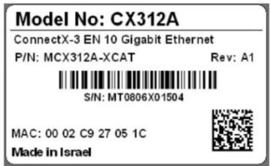
1.3 Finding the MAC and Serial Number on the Adapter Card
Each Mellanox adapter card has a label on the print side that shows the card serial number and the card MAC for the Ethernet protocol.
Figure 1: Card Product Label (Example)
1.4 Safety Warnings
Below is a list of safety warnings in English. For safety warnings in other languages, please refer to the appendices in this user manual.
1. Installation Instructions

Read all installation instructions before connecting the equipment to the power source.
2. Over-temperature

This equipment should not be operated in an area with an ambient temperature exceeding the maximum recommended: 55°C (131°F).
To guarantee proper air flow, allow at least 8cm (3 inches) of clearance around the ventilation openings.
3. During Lightning - Electrical Hazard

During periods of lightning activity, do not work on the equipment or connect or disconnect cables.
4. Copper Cable Connecting/Disconnecting

Some copper cables are heavy and not flexible, as such they should be carefully attached to or detached from the connectors. Refer to the cable manufacturer for special warnings and instructions.
5. Equipment Installation

This equipment should be installed, replaced, or serviced only by trained and qualified personnel.
6. Equipment Disposal

Disposal of this equipment should be in accordance to all national laws and regulations.
7. Local and National Electrical Codes

This equipment should be installed in compliance with local and national electrical codes.
8. Hazardous Radiation Exposure

Caution - Use of controls or adjustment or performance of procedures other than those specified herein may result in hazardous radiation exposure.

CLASS 1 LASER PRODUCT and reference to the most recent laser standards: IEC 60 825-1:1993 + A1:1997 + A2:2001 and EN 60825-1:1994+A1:1996+A2:2001
2 Adapter Card Interfaces
2.1 I/O Interfaces
Each adapter card includes the following interfaces:
- SFP+ port(s)
- PCI Express (PCIe) x4 or x8 edge connector
- I/O panel LEDs
- I ^2 C-compatible connector (for debug)
Figure 2: MCX312A-XCBT Card
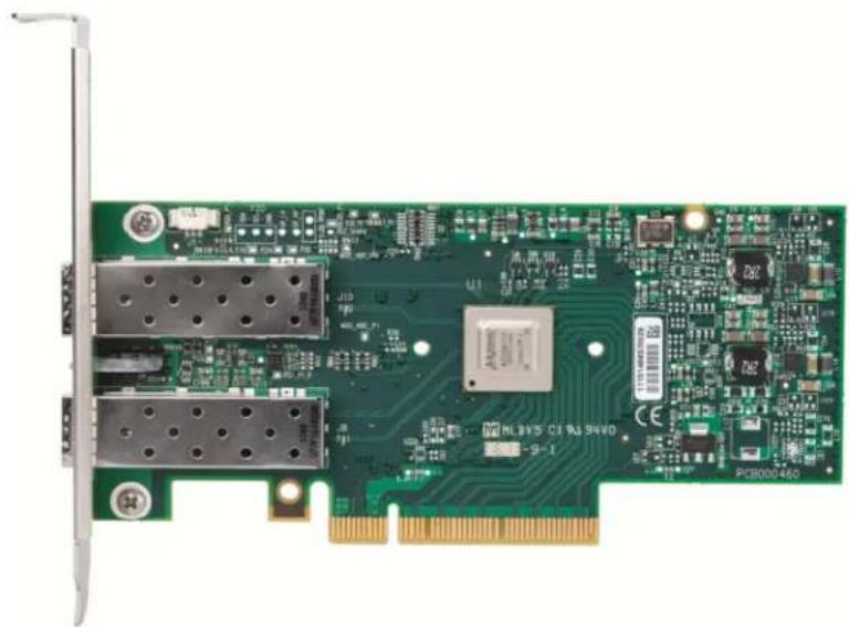
natural_image
Green PCI 8000460 microcontroller board with dual ports and a central chip (no readable text or symbols)Figure 3: MCX311A-XCAT Card
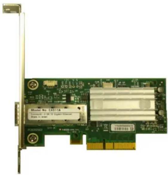
The adapter cards include special circuits to protect from ESD shocks to the card/server when plugging copper cables.
Figure 4: Dual-port Bracket
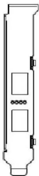
natural_image
Pure technical line drawing of a vertical cylindrical component with three internal square cutouts (no text or symbols)Figure 5: Single-port Bracket

natural_image
Pure technical line drawing of a vertical cylindrical component with internal components (no text or symbols)For dual-port cards, Port 1 connects to connector 1 of the device, while Port 2 connects to connector 2 of the device.
2.1.1 Ethernet SFP+ Interface
The network ports of the ConnectX®-3 adapter cards are compliant with the IEEE 802.3 Ethernet standards listed in Section 1.1.1, "10 Gigabit Ethernet," on page 10. The SFP+ port has one Tx/Rx pair of SerDes. Ethernet traffic is transmitted through the cards' SFP+ connectors.
2.1.2 PCI Express Interface
The ConnectX®-3 adapter cards support PCI Express 3.0 (1.1 and 2.0 compatible) through an x4 or x8 edge connector. The device can be either a master initiating the PCI Express bus operations or a slave responding to PCI bus operations.
2.1.3 LED Assignment
There are two I/O LEDs per port in dual-port designs and one bicolor LED in single-port designs, green and yellow, located on the I/O panel. See Table 4 for different LED functions.
Table 4 - Physical and Logical Link Indication
| LED Function | |
| Green - physical link | Constant on indicates a good physical linkIf neither LED is lit, then the physical link has not been established |
| Yellow - logical (data activity link) | A blinking yellow indicates activity (data transfer)Stays off when there is no activity |

The short bracket has the same port and LED footprints as the tall bracket.
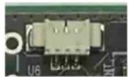
2.1.4 I ^2 C-compatible Interface
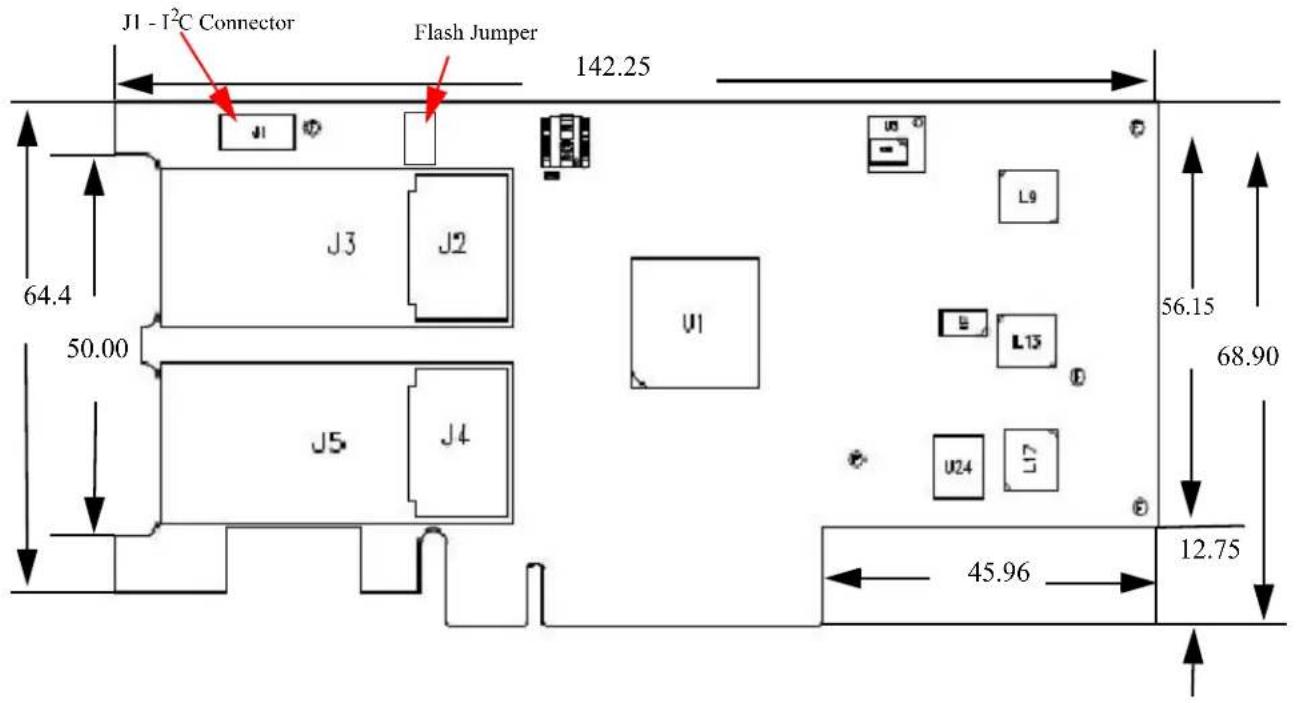
A three-pin header on the adapter cards is provided as the I ^2 C-compatible interface. See Figure 13, "Mechanical Drawing of the Dual-port MCX312A-XCBT Adapter Card," on page 37 for the location on the board.
Figure 6: I²C-compatible Connector
2.2 Power
All adapter cards receive 12V and 3.3V power from the PCI Express edge connector. All other required power voltages are generated by on-board switch mode regulators. See “Specifications” on page 34.
2.3 SFP+ Power Level
The adapter cards support power levels according to SFF Committee SFF-8431 Specification for SFP+ (Small Form-factor Pluggable) Transceiver.
2.4 Memory
The adapter cards support multiple memory devices through the PCIe, SPI (Flash) and I ^2 C interfaces.
2.4.1 System Memory
The adapter cards utilize the PCI Express interface to store and access Ethernet fabric connection information and packet data on the system memory.
2.4.2 SPI
Each of the adapter cards includes one 16MB SPI Flash device (M25PX16-VMN6P device by ST Microelectronics) accessible via the SPI interface of the ConnectX®-3 EN device.
When a jumper is inserted into the drill holes in the adapter it indicates to the device that the onboard Flash device should not be used for boot instructions. Contact your Mellanox support representative should you need to use this jumper. Table 5 provides information on this jumper. The
jumper location on the board is illustrated in Appendix A.3, "Board Mechanical Drawing and Dimensions," on page 36.
Table 5 - Jumper Configuration
| Description Option | Card Default Configuration | |
| Flash present/not present | connection open – Flash present connection shorted – Flash not present connection shorted – Flash not present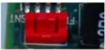 | connection open – Flash present |
2.4.3 EEPROM
Each board incorporates an EEPROM that is accessible through the I ^2 C-compatible interface. The EEPROM capacity is 4Kb. The EEPROM is used for storing the Vital Product Data (VPD).
The PCI VPD (Vital Product Data) layout for each of the adapter cards complies with the format defined in the PCI 3.0 Specification, Appendix I.
Table 6 - MCX312A-XCBT VPD Layout
| Offset (Decimal) | Item ValueFormat | Description | ||
| 0 Large R | Resource Type ID String Tag (0x02) | 0x82 | ||
| 1 Length | [7:0] LSB 0x18 | |||
| 2 Length | [15:8] MSB 0x0 | |||
| 3 Data | CX312A - Con-nectX-3 SFP+ | STR | ||
| 27 | Large Resource Type VPD-R Tag (0x10) | 0x90 | ||
| 28 | Length [7:0] LSB 0x4F | |||
| 29 | Length [15:8] MSB | 0x00 | ||
| 30 | VPD Keyword | PN | STR | Add in Card Part Number |
| 32 | Length | 0x15 | ||
| 33 | Part Number | PN | %STR_SPC | |
| 54 | VPD Keyword | EC | STR | Engineering Change Level of the card (rev) |
| 56 | Length 0x2 | |||
| 57 | Revision | RV | %STR | PCB revision |
| 59 | VPD Keyword | SN | STR | Serial Number |
| 61 | Length | 0x18 | ||
| 62 | SerialNumber | SN | %STR_SPC | “00..00XXXX..XX” |
| Offset (Decimal) | Item | Value | Format | Description |
| 86 | VPD Keyword | V0 | STR | Misc Information |
| 88 Length | 0x10 | |||
| 89 Data PCIe Gen3 x8 STR_SPC | ||||
| 105 VPD Keyword RVSTR | ||||
| 107 Length | 0x1 | |||
| 108 | Data | 0,107 | %CS0 | |
| 109 | Large Resource Type VPD-W Tag (0x11) | 0x91 | ||
| 110 | Length [7:0] LSB | 0x8F | ||
| 111 | Length [15:8] MSB | 0xF | ||
| 112 | VPD Keyword | V1 | STR | EFI Driver version |
| 114 | Length 0x6 | |||
| 115 | Data | N/A | STR_SPC | |
| 121 | VPD Keyword | YA | STR | Asset Tag |
| 123 Length | 0x18 | |||
| 124 | Data | N/A | STR_SPC | “N/A” |
| 148 | VPD Keyword | RW | STR | Remaining read/write area |
| 150 Length | 0x69 | |||
| 151 | Data | STR_ZERO | Reserved (0x00) | |
| 256 | VPD Keyword | RW | STR | Remaining read/write area |
| 258 Length | 0xfd | |||
| 259 | Data | STR_ZERO | Reserved (0x00) | |
| 512 | VPD Keyword | RW | STR | Remaining read/write area |
| 514 Length | 0xfd | |||
| 515 | Data | STR_ZERO | Reserved (0x00) | |
| 768 | VPD Keyword | RW | STR | Remaining read/write area |
| 770 Length | 0xfd | |||
| 771 | Data | STR_ZERO | Reserved (0x00) | |
| 1024 | VPD Keyword | RW | STR | Remaining read/write area |
| 1026 Length | 0xfd | |||
| 1027 | Data | STR_ZERO | Reserved (0x00) | |
| 1280 | VPD Keyword | RW | STR | Remaining read/write area |
| 1282 Length | 0xfd | |||
| 1283 | Data | STR_ZERO | Reserved (0x00) | |
| 1536 | VPD Keyword | RW | STR | Remaining read/write area |
| 1538 Length | 0xfd | |||
| 1539 | Data | STR_ZERO | Reserved (0x00) | |
| 1792 | VPD Keyword | RW | STR | Remaining read/write area |
| 1794 Length | 0xfd | |||
| 1795 | Data | STR_ZERO | Reserved (0x00) | |
| 2048 | VPD Keyword | RW | STR | Remaining read/write area |
| 2050 Length | 0xfd | |||
| 2051 | Data | STR_ZERO | Reserved (0x00) | |
| 2304 | VPD Keyword | RW | STR | Remaining read/write area |
| Offset (Decimal) | Item Value Format | Description | ||
| 2306 Length 0xfd | ||||
| 2307 Data STR_ZERO Reserved (0x00) | ||||
| 2560 | VPD Keyword | RW | STR | Remaining read/write area |
| 2562 Length 0xfd | ||||
| 2563 Data STR_ZERO Reserved (0x00) | ||||
| 2816 | VPD Keyword | RW | STR | Remaining read/write area |
| 2818 Length 0xfd | ||||
| 2819 Data STR_ZERO Reserved (0x00) | ||||
| 3072 | VPD Keyword | RW | STR | Remaining read/write area |
| 3074 Length 0xfd | ||||
| 3075 Data STR_ZERO Reserved (0x00) | ||||
| 3328 | VPD Keyword | RW | STR | Remaining read/write area |
| 3330 Length 0xfd | ||||
| 3331 Data STR_ZERO Reserved (0x00) | ||||
| 3584 | VPD Keyword | RW | STR | Remaining read/write area |
| 3586 Length 0xfd | ||||
| 3587 Data STR_ZERO Reserved (0x00) | ||||
| 3840 | VPD Keyword | RW | STR | Remaining read/write area |
| 3842 Length 0xfc | ||||
| 3843 Data STR_ZERO Reserved (0x00) | ||||
| 4095 Small Resource Type END Tag (0x11) | 0x78 | |||
Table 7 - MCX311A-XCAT VPD Layout
| Offset (Decimal) | Item Value Format | Description | ||
| 0 | Large Resource Type ID String Tag (0x02) | 0x82 | ||
| 1 | Length [7:0] LSB | 0x18 | ||
| 2 Length [15:8] MSB 0x0 | ||||
| 3 Data | CX311A - Con-nectX-3 SFP+ | STR | ||
| 27 Large Resource Type VPD-R Tag (0x10) | 0x90 | |||
| 28 | Length [7:0] LSB | 0x4F | ||
| 29 | Length [15:8] MSB | 0x00 | ||
| 30 | VPD Keyword | PN | STR | Add in Card Part Number |
| 32 Length | 0x15 | |||
| 33 | Part Number | PN | %STR_SPC | |
| 54 | VPD Keyword | EC | STR | Engineering Change Level of the card (rev) |
| 56 Length | 0x2 | |||
| 57 | Revision | RV | %STR | PCB revision |
| 59 | VPD Keyword | SN | STR | Serial Number |
Table 7 - MCX311A-XCAT VPD Layout
| Offset (Decimal) | Item | Value | Format | Description |
| 61 Length | 0x18 | |||
| 62 | SerialNumber | SN | %STR_SPC | “00..00XXXX..XX” |
| 86 | VPD Keyword | V0 | STR | Misc Information |
| 88 Length | 0x10 | |||
| 89 Data PCIe Gcn3 x4 STR_SPC | ||||
| 105 | VPD Keyword | RV | STR | |
| 107 | Length | 0x1 | ||
| 108 | Data | 0,107 | %CS0 | |
| 109 | Large Resource Type VPD-W Tag (0x11) | 0x91 | ||
| 110 | Length [7:0] LSB | 0x8F | ||
| 111 | Length [15:8] MSB | 0xF | ||
| 112 | VPD Keyword | V1 | STR | EFI Driver version |
| 114 | Length | 0x6 | ||
| 115 | Data | N/A | STR_SPC | |
| 121 | VPD Keyword | YA | STR | Asset Tag |
| 123 | Length 0x18 | |||
| 124 | Data | N/A | STR_SPC | “N/A” |
| 148 | VPD Keyword | RW | STR | Remaining read/write area |
| 150 | Length 0x69 | |||
| 151 | Data | STR_ZERO | Reserved (0x00) | |
| 256 | VPD Keyword | RW | STR | Remaining read/write area |
| 258 | Length | 0xfd | ||
| 259 | Data | STR_ZERO | Reserved (0x00) | |
| 512 | VPD Keyword | RW | STR | Remaining read/write area |
| 514 | Length | 0xfd | ||
| 515 | Data | STR_ZERO | Reserved (0x00) | |
| 768 | VPD Keyword | RW | STR | Remaining read/write area |
| 770 | Length | 0xfd | ||
| 771 | Data | STR_ZERO | Reserved (0x00) | |
| 1024 | VPD Keyword | RW | STR | Remaining read/write area |
| 1026 Length | 0xfd | |||
| 1027 | Data | STR_ZERO | Reserved (0x00) | |
| 1280 | VPD Keyword | RW | STR | Remaining read/write area |
| 1282 Length | 0xfd | |||
| 1283 | Data | STR_ZERO | Reserved (0x00) | |
| 1536 | VPD Keyword | RW | STR | Remaining read/write area |
| 1538 Length | 0xfd | |||
| 1539 | Data | STR_ZERO | Reserved (0x00) | |
| 1792 | VPD Keyword | RW | STR | Remaining read/write area |
| 1794 Length | 0xfd | |||
| 1795 | Data | STR_ZERO | Reserved (0x00) | |
| 2048 | VPD Keyword | RW | STR | Remaining read/write area |
Table 7 - MCX311A-XCAT VPD Layout
| Offset (Decimal) | Item Value Format | Description | ||
| 2050 Length 0xfd | ||||
| 2051 Data STR_ZERO Reserved (0x00) | ||||
| 2304 | VPD Keyword | RW | STR | Remaining read/write area |
| 2306 Length 0xfd | ||||
| 2307 Data STR_ZERO Reserved (0x00) | ||||
| 2560 | VPD Keyword | RW | STR | Remaining read/write area |
| 2562 Length 0xfd | ||||
| 2563 Data STR_ZERO Reserved (0x00) | ||||
| 2816 | VPD Keyword | RW | STR | Remaining read/write area |
| 2818 Length 0xfd | ||||
| 2819 Data STR_ZERO Reserved (0x00) | ||||
| 3072 | VPD Keyword | RW | STR | Remaining read/write area |
| 3074 Length 0xfd | ||||
| 3075 Data STR_ZERO Reserved (0x00) | ||||
| 3328 | VPD Keyword | RW | STR | Remaining read/write area |
| 3330 Length 0xfd | ||||
| 3331 Data STR_ZERO Reserved (0x00) | ||||
| 3584 | VPD Keyword | RW | STR | Remaining read/write area |
| 3586 Length 0xfd | ||||
| 3587 Data STR_ZERO Reserved (0x00) | ||||
| 3840 | VPD Keyword | RW | STR | Remaining read/write area |
| 3842 Length 0xfc | ||||
| 3843 Data STR_ZERO Reserved (0x00) | ||||
| 4095 Small | Resource Type END Tag (0x11) | 0x78 | ||
3 Ethernet Adapter Card Installation
3.1 Hardware Requirements
A system with a PCI Express x4 or x8 slot is required for installing the card.
3.2 Installation Instructions
Read all installation instructions before connecting the equipment to the power source.

To change a tall bracket to a short bracket see Replacing a Tall Bracket With a Short Bracket on page 42.
The adapter cards listed above are standard PCI Express cards, each with a standard x8 edge connector. The cards require a PCI Express x4 or x8. Please consult the host machine documentation for instructions on how to install a PCI Express card.

If the card is installed in a PCI slot with less lanes than the card requires then the adapter card will not provide the optimum data transfer.
3.3 Identify the Card in Your System
3.3.1 On Windows
- Open Device Manager on the server. Click start => Run, and then enter "devmgmt.msc".
- Expand System Devices and locate yo ur Mellanox ConnectX-3 adapter card.
- Select Properties to display the adapter card properties window.
- Click the Details tab and select D evice Instance Id (Windows 2003) or Hardware Ids (Windows 2008/R2) from the Property pull-down menu.
Figure 7: PCI Device
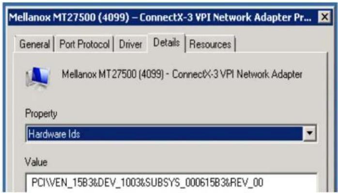
- In the Value display box, check the fields VEN and DEV (fields are separated by '&'). In the display example above, notice the sub-string "PCI\VEN_15B3&DEV_1003": VEN is equal to 0x15B3 – this is the Vendor ID of Mellanox Technologies; and DEV is equal to 1003 – this is a valid Mellanox Technologies PCI Device ID.

If the PCI device does not have a Mellanox adapter ID, return to Step 4 to check another device.

The list of Mellanox Technologies PCI Device IDs can be found in the PCI ID repository at http://pci-ids.ucw.cz/read/PC/15b3.
3.3.2 On Linux
Get the device location on the PCI bus by running lspci and locating lines with the string "Mellanox Technologies":
> lspci | grep -i Mellanox
27:00.0 Network controller: Mellanox Technologies MT27500 Family [ConnectX-3]
3.4 Cables and Modules
Please refer to "Mellanox Products Approved Cable Lists" at http://www.mellanox.com/related-docs/user_manuals/Mellanox_approved_cables.pdf
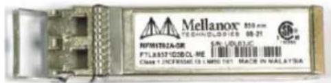
3.4.1 Inserting the Optical Transceiver Module
To insert the module into the cage:
-
Open the module's loc king mechanism – see Figure 8 and Figure 9.
-
Make sure that the male connectors on the module will align with the female connectors inside of the cage. Also check that there is no dirt or foreign matter in the module or in the cage.
Figure 8: Module With Locking Mechanism Closed
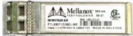
Figure 9: Module With Locking Mechanism Open
- Insert the module into the adapter card module cage.
- Close the locking Mechanism.
To remove the module from the cage:
- Unlock the locking mechanism by opening the handle.
- Pull the module out of the cage.
3.4.2 Cable Installation
- All cables can be inserted or removed with the unit powered on. To insert a cable, press the connector into the port receptacle until the connector is firmly seated.
- After inserting a cable into a port, the GREEN LED indicator will 1 light when the physical connection is established (that is, when the unit is powered on and a cable is plugged into the port with the other end of the connector plugged into a functioning port).
- After plugging in a cable, lock the connec tor using the latching mechanism particular to the cable vendor. When a logical connection is made the YELLOW LED will come on. When data is being transferred the yellow led will blink.

When installing cables make sure that the latches engage.

Always install and remove cables by pushing or pulling the cable and connector in a straight line with the card.
- Care should be taken as not to impede the air exhaust flow through the ventilation holes. Cable lengths which allow for routing horizontally around to the side of the chassis before bending upward or downward in the rack should be used
- To remove a cable, disengage the locks and slowly pull the connector away from the port receptacle. Both LED indicators will turn off when the cable is unseated.

Cables, especially long copper cables, can weigh a substantial amount. Make sure that the weight of the cable is supported on its own and is not hanging from the adapter card.
4 Driver Software and Firmware
4.1 Driver Software
4.1.1 Linux
For Linux, download and install the latest MLNX_EN driver software package available via the Mellanox web site at: http://www.mellanox.com => Products => Software/Drivers => Ethernet SW/Drivers => ConnectX®-3 EN 10GigE Linux Driver => Download. Follow the installation instructions included in the download package (also available from the download page). To ensure that communication has been established follow the instructions below.
Check the link status
First check the network interface name by running the "ifconfig -a" command
To assign an IP address to the interface run:
> ifconfig eth<x><ip>
where 'x' is the OS assigned interface number.
To check driver and device information run:
> ethtool -i eth<x>
Example:
> ethtool -i eth2
driver:mlx4_en (MT_1020110019_CX-3)
version: 1.5.6.33 (Oct 2011)
firmware-version:2.10.0000
bus-info: 0000:07:00.0
4.1.2 Windows
For Windows, download the MLNX EN – Ethernet driver. Download this package from the Mellanox web site at: http://www.mellanox.com => Products => Software/Drivers => Ethernet SW/Drivers => ConnectX® EN 10GigE Windows Driver => Download. Follow the installation
instructions included in the download package (also available from the download page). To ensure that communication has been established follow the instructions below.
To display a summary of network adapter software-, firmware- and hardware-related information such as driver version, firmware version, bus interface, adapter identity, and network port link information, perform the following steps:
Step 1: Display the Device Manager
Figure 10: Device Manager
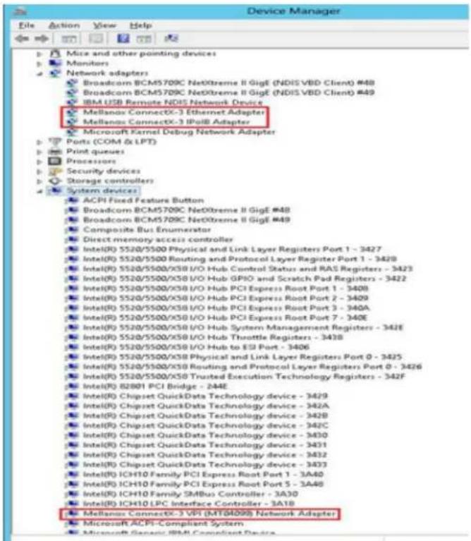
Step 2: Right-click a Mellanox ConnectX Ethernet adapter (under "Network adapters list) and left-click Properties.
Step 3: Select the Information tab from the Properties sheet (example).
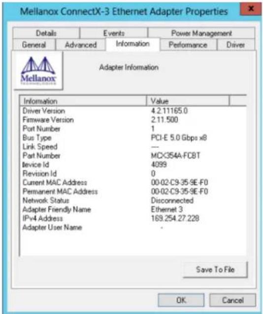

To save this information for debug purposes, click Save To File and provide the output file name.
4.2 FlexBoot
FlexBoot enables remote boot over Ethernet, Boot over Ethernet (BoE) or Boot over iSCSI (BoiSCSI). This technology is based on the Preboot Execution Environment (PXE) standard specification, and FlexBoot software is based on the open source iPXE project (see www.ipxe.org). For more information go to http://www.mellanox.com => Products => Software/Drivers => InfiniBand & VPI Software/Drivers => FlexBoot => Download.
4.3 RDMA over Converged Ethernet
ConnectX®-3 connected to an Ethernet fabric provides all of the basic NIC functionality plus RDMA over Converged Ethernet (RoCE). RoCE utilizes advances in Data Center Bridging (DCB) to enable efficient and low cost implementations of RDMA over Ethernet, supporting the entire breadth of RDMA and low latency features. This includes reliable connected service, datagram service, RDMA and send/receive semantics, atomic operations, user level multicast, user level I/O access, kernel bypass, and zero copy. This capability is enabled when using the Mellanox OFED or WinOF VPI drivers.
ConnectX®-3 EN with RoCE based network management is the same as that for any Ethernet and DCB-based network management, eliminating the need for IT managers to learn new technologies.
4.3.1 Hardware and Software Requirements
Software:
- Mellanox OFED 1.5.1 or WinOF 2.1.2 or later. To download these packages go to www.mellanox.com => Products => Software/Drivers => InfiniBand & VPI SW/Driver.
Hardware:
- ConnectX®-3 EN adapter card
4.4 Updating Adapter Card Firmware
Each card is shipped with the latest version of qualified firmware at the time of manufacturing. Firmware is updated occasionally, and the most recent firmware can be obtained from:
http://www.mellanox.com => Support => Download Firmware. Check that the firmware on your card is the latest found on the Mellanox site, if not update to the latest version found on the Mellanox web site.
Firmware can be updated on the stand alone single card using the flint tool of the Mellanox Firmware Tools (MFT) package. This package is available for download, along with its user manual, from the Mellanox Firmware Tools page. See http://www.mellanox.com => Support => Download Firmware Tools.
A firmware binaries table lists a binary file per adapter card. The file name of each such binary is composed by combining the firmware name, the firmware release version, and the card part number. Please contact Mellanox System Support if you cannot find the firmware binary for your adapter card.
The following steps describe how to retrieve the PSID (firmware identification) and programmed firmware version of your adapter card. They also describe how to update the card with the latest firmware version available.
- Retrieve the PSID and firmware version:
a. Install the MFT package. The package is available at www.mellanox.com => Products => Software/Drivers => Ethernet Software/Drivers => Firmware Tools. Make sure to download the package corresponding to your computer's operating system.
b. Enter: mst start.
c. Get the Mellanox mst device name using the command "mst status". The mst device name will be of the form: /dev/mst/mt4099_pci_cr0.
d. Get the PSID (firmware identification) and programmed firmware version using the command.
> flint -d /dev/mst/mt4099_pci_cr0 q
Image type: ConnectX
FW Version: 2.9.4000
Device ID: 4099
Chip Revision: 0
Description: Node Port1
Port2 Sys image
GUIDs: 000002c900000200 000002c900000201
000002c900000202 000002c900000203
MACs:
000002c90200 000002c90201
Board ID: (MT_1020110019)
VSD:
PSID: MT_1020110019
- Compare the programmed firmware version with the latest available.
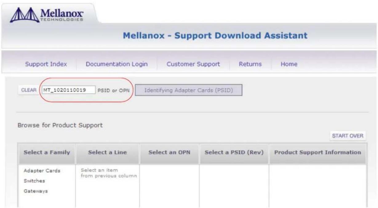
a. Go to Mellanox's web site: http://www.mellanox.com/supportdownloader. See Figure 11.
b. Enter your card PSID to display the latest firmware.
Figure 11: Support Download Assistant
- If a newer firmware version exists for your adapter card, update the firmware as follows:
a. Download the firmware image zip file from the Download Center (see Step 2a above).
b. Unzip the firmware image.
c. Burn the firmware image. Enter:
> flint -d /dev/mst/mt4099_pci_cr0 -i <binary image> burn
d. Reboot the computer.
e. Enter: mst start.
f. Verify that the card firmware was updated successfully.
> flint -d /dev/mst/mt4099_pci_cr0 q
Image type: ConnectX
FW Version: 2.9.4100
Device ID: 4099
...
Appendix A: Specifications
A.1 MCX311A-XCAT Specifications
Table 8 - MCX311A-XCAT Specifications Table
| Physical | Size: 2.11in. x 4.18 in. (53.59mm x 106.06 mm) |
| Connector: SFP+ 10Gb/s | |
| Protocol Support | Ethernet: XAUI/10GBASE-KX4 - 4X 10GigE port, XFI/SFI/10GBASE-KR - 1X 10GigE port, SGMII/1000BASE-KX - 1X 1GigE port |
| Data Rate: 1/10Gb/s - Ethernet | |
| PCI Express Gen3: SERDES @ 8.0GT/s, 4 lanes (2.0 and 1.1 compatible) | |
| Power and Environmental | Voltage: 12V, 3.3V |
| Typ Power: Passive Cables 3.47W | |
| Max Power: Passive Cables 4.84W | |
| Temperature: Operational 0°C to 55°CNon-operational 0°C to 70°C | |
| Humidity: 90% relative humiditya | |
| Air Flow: 200LFMb | |
| Regulatory | EMC: Refer to the following link:www.mellanox.com/related-docs/user_manuals/Regulatory_and_Compliance_Guide.pdf |
| Safety: IEC/EN 60950-1:2006ETSI EN 300 019-2-2IEC 60068-2- 64, 29, 32 | |
| RoHS: RoHS-R6 | |
| Cable Support | Please refer to "Mellanox Products Approved Cable Lists" at www.mellanox.com/related-docs/user_manuals/Mellanox_approved_cables.pdf |
a. For both operational and non-operational states
b. Air flow is measured \~1" from the heat sink between the heat sink and the cooling air inlet.
A.2 MCX312A-XCBT Specifications
Table 9 - MCX312A-XCBT Specifications Table
| Physical | Size: 2.71in. x 5.6in. (68.90 mm x 142.25 mm) |
| Connector: SFP+ 10Gb/s | |
| Protocol Support | Ethernet: 10GBASE-CX4, 10GBASE-R, and 1000BASE-R |
| Data Rate: 1/10Gb/s - Ethernet | |
| PCI Express Gcn3: SERDES @ 8.0GT/s, 4 lanes (2.0 and 1.1 compatible)PCI Express Gcn2: SERDES @ 5.0GT/s, 8 lanes (1.1 compatible) | |
| Power and Environmental | Voltage: 12V, 3.3V |
| Typ Power: PCIe x4 Gen3Passive Cables 3.83WPCIe x8 Gen2Passive Cables 5.31W | |
| Max Power: PCIe x4 Gen3Passive Cables 4.55WPCIe x8 Gen2Passive Cables 6.20W | |
| Temperature: Operational 0°C to 55°CONon-operational 0°C to 70°C | |
| Humidity: 90% relative humiditya | |
| Air Flow: 200LFMb | |
| Regulatory | EMC: Refer to the following link:www.mellanox.com/related-docs/user_manuals/Regulatory_and_Compliance_Guide.pdf |
| Safety: IEC/EN 60950-1:2006ETS1 EN 300 019-2-2IEC 60068-2- 64, 29, 32 | |
| RoHS: RoHS-R6 | |
| Cable Support | Please refer to "Mellanox Products Approved Cable Lists" at www.mellanox.com/related-docs/user_manuals/Mellanox_approved_cables.pdf |
a. For both operational and non-operational states
b. Air flow is measured \~1" from the heat sink between the heat sink and the cooling air inlet.
A.3 Board Mechanical Drawing and Dimensions

All dimensions are in millimeters. All the mechanical tolerances are +/- 0.1mm
Figure 12: Mechanical Drawing of the Dual-port MCX311A-XCAT Adapter Card
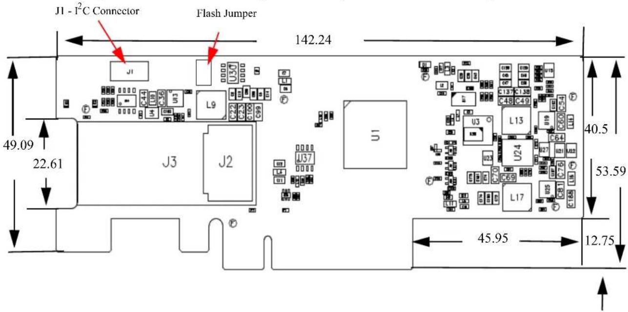
Figure 13: Mechanical Drawing of the Dual-port MCX312A-XCBT Adapter Card
A.4 Regulatory Statements
For regulatory statements for all ConnectX®-3 cards please refer to: http://www.mellanox.com/related-docs/user_manuals/Regulatory_and_Compliance_Guide.pdf
Appendix B: Interface Connectors Pinout
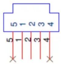
B.1 I ^2 C-compatible Connector Pinout
Figure 14: Compatible Connector Plug and Pinout
Table 10 - I2C-compatible Connector Pinout
| Connector Pin Number Signal Name | |
| 1 | S |
| 2 SPSCL | |
| 3 GND | |
| 4 | NC |
| 5 | NC |
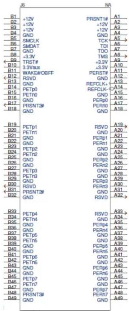
B.2 PCI Express x8 Connector Pinout
The adapter cards use a standard PCI Express x4 or x8 edge connector and the PCI Express x8 standard pinout according to the PCI Express 3.0 specification.
Figure 15: PCIe Connector Pinout
B.3 SFP+ Connector Pinout
Figure 16: Rear View of Module With Pin Placement
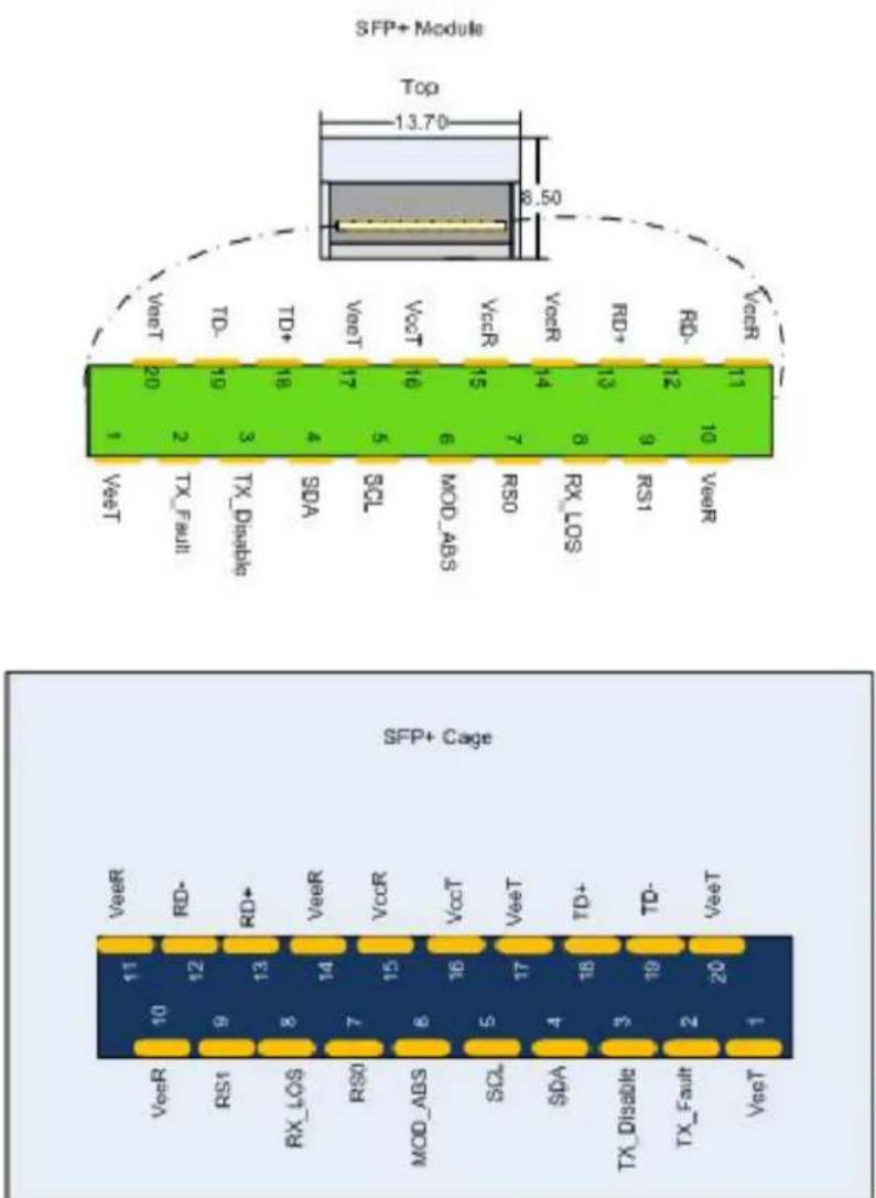
Table 11 - SFP+ Connector Pinout
| Pin Symbol Name Description | ||
| 1 VeeT | Transmitter Ground (Common with Receiver Ground )a | |
| 2 TX_Fault | Transmitter Fault.^b | |
| 3 TX_Disable | Transmitter Disable. Laser output disabled on high or open. c | |
| 4 SDA | 2-wire Serial Interface Data Line^d | |
| 5 SCL | 2-wire Serial Interface Clock Line^d | |
| 6 MOD_ABS | Module Absent. Grounded within the module^d | |
| 7 RS0 No connection required | ||
| 8 RX_LOS | Loss of Signal indication. Logic 0 indicates normal operation. c | |
| 9 RS1 No connection required | ||
| 10 VeeR | Receiver Ground (Common with Transmitter Ground )a | |
| 11 VeeR | Receiver Ground (Common with Transmitter Ground )a | |
| 12 | RD- | Receiver Inverted DATA out. AC Coupled |
| 13 | RD+ | Receiver Non-inverted DATA out. AC Coupled |
| 14 | VeeR | Receiver Ground (Common with Transmitter Ground )a |
| 15 | VccR | Receiver Power Supply |
| 16 | VccT | Transmitter Power Supply |
| 17 | VeeT | Transmitter Ground (Common with Receiver Ground )a |
| 18 | TD+ | Transmitter Non-Inverted DATA in. AC Coupled. |
| 19 | TD- | Transmitter Inverted DATA in. AC Coupled. |
| 20 | VeeT | Transmitter Ground (Common with Receiver Ground )a |
a. Circuit ground is internally isolated from chassis ground.
b. T_FAULT is an open collector/drain output, which should be pulled up with a 4.7k – 10k Ohms resistor on the host board if intended for use. Pull up voltage should be between 2.0V to Vcc + 0.3V. A high output indicates a transmitter fault caused by either the TX bias current or the TX output power exceeding the preset alarm thresholds. A low output indicates normal operation. In the low state, the output is pulled to <0.8V.
c. Laser output disabled on TDIS >2.0V or open, enabled on TDIS <0.8V
d. Should be pulled up with 4.7k - 10k on host board to a voltage between 2.0V and 3.6V. MOD_ABS pulls line low to indicate module is plugged in.
e. LOS is open collector output. Should be pulled up with 4.7k - 10k on host board to a voltage between 2.0V and 3.6V. Logic 0 indicates normal operation; logic 1 indicates loss of signal.
Appendix C: Replacing a Tall Bracket With a Short Bracket
This section provides instructions on how to remove the tall bracket of a standard Mellanox Technologies adapter card and replace it with a short one.
C.1 Replacing a Bracket
To replace the bracket you will need the following parts:
• the new bracket of the proper height
• one new square gasket for each of the ports
• the 2 screws saved from the removal of the bracket
• the 2 fiber washers saved from the removal of the bracket
C.2 Removing the Existing Bracket from the Adapter Card
Figure 17: Bracket Screws
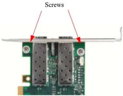
- Remove the two screws holding the bracket in place.
- The bracket comes loose from the card.

Be careful not to put stress on the LEDs.
- Save the two screws and the two fiber washers.
C.3 Installing the New Bracket
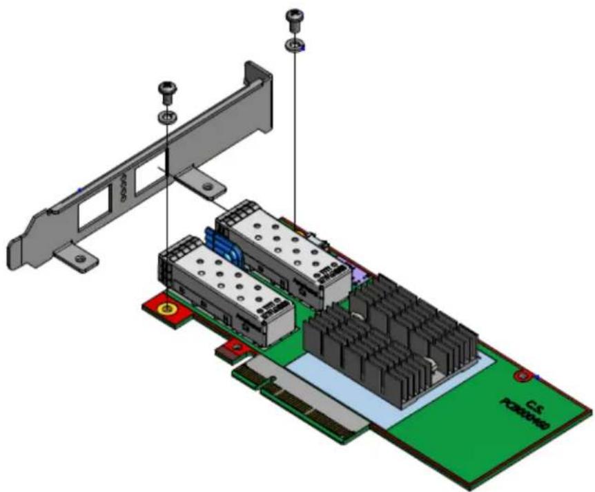
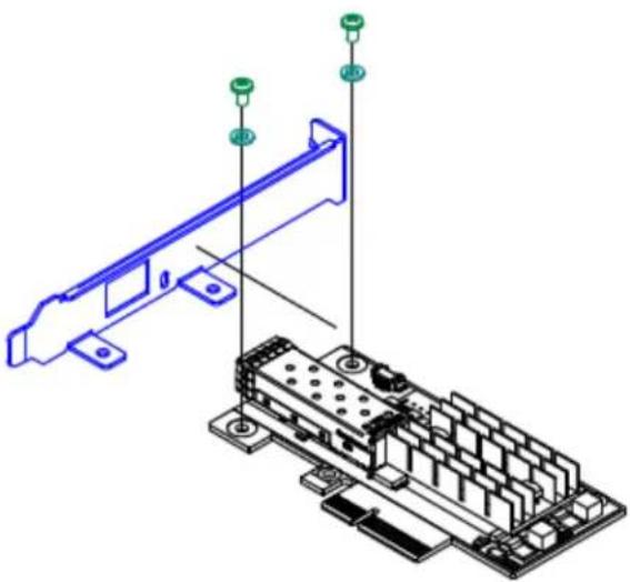
- Place the bracket onto the card until the screw holes line up.

Do not force the bracket onto the card. You may have to gently push the LEDs using a small screwdriver to align the LEDs with the holes in the bracket.
- Screw on the bracket using the screws and washers saved from the procedure above step 1.
Figure 18: Placing the Bracket on the Card (MCX312A-XCBT)
natural_image
3D technical diagram of a computer motherboard with RAM slots and connectors (no text or symbols)Figure 19: Placing the Bracket on the Card (MCX311A-XCAT)
natural_image
Isometric technical diagram of a computer motherboard with connectors and components (no text or symbols)- Make sure that the LEDs are aligned onto the bracket holes.
- Use a torque driver to apply up to 2 lbs-in torque on the screws.
This equipment should be installed in compliance with local and national electrical codes.
8. Strahlenkontak

- ConnectX®-3 Ethernet Single and Dual SFP+ Port Adapter Card User Manual
- NOTE:
- Table of Contents
- Table of Contents .... 3
- List of Tables 5
- List of Figures ...... 6
- Revision History 7
- About this Manual 8
- Chapter 1 Overview.... 10
- Chapter 2 Adapter Card Interfaces ...... 14
- Chapter 3 Ethernet Adapter Card Installation.... 24
- Chapter 4 Driver Software and Firmware 28
- Appendix A Specifications.... 34
- Rev 1.6
- Appendix B Interface Connectors Pinout 38
- Appendix C Replacing a Tall Bracket With a Short Bracket 42
- Appendix E Sicherheitshinweise (Warnings in German).... 47
- List of Figures
- Revision History
- About this Manual
- Intended Audience
- Related Documentation
- Document Conventions
- Technical Support
- Firmware and Software Updates
- Overview
- Supported Network Protocol Standards
- 10 Gigabit Ethernet
- Adapter Cards Covered in this Manual
- Finding the MAC and Serial Number on the Adapter Card
- Safety Warnings
- Installation Instructions
- Over-temperature
- During Lightning - Electrical Hazard
- Copper Cable Connecting/Disconnecting
- Equipment Installation
- Equipment Disposal
- Local and National Electrical Codes
- Hazardous Radiation Exposure
- Adapter Card Interfaces
- I/O Interfaces
- Ethernet SFP+ Interface
- PCI Express Interface
- LED Assignment
- I 2 C-compatible Interface
- Power
- SFP+ Power Level
- Memory
- System Memory
- SPI
- EEPROM
- Ethernet Adapter Card Installation
- Hardware Requirements
- Installation Instructions
- Identify the Card in Your System
- On Windows
- On Linux
- Cables and Modules
- Inserting the Optical Transceiver Module
- Cable Installation
- Driver Software and Firmware
- Driver Software
- Linux
- Check the link status
- Windows
- FlexBoot
- RDMA over Converged Ethernet
- Hardware and Software Requirements
- Software:
- Hardware:
- Updating Adapter Card Firmware
- Appendix A: Specifications
- A.1 MCX311A-XCAT Specifications
- A.2 MCX312A-XCBT Specifications
- A.3 Board Mechanical Drawing and Dimensions
- A.4 Regulatory Statements
- Appendix B: Interface Connectors Pinout
- B.1 I 2 C-compatible Connector Pinout
- B.2 PCI Express x8 Connector Pinout
- B.3 SFP+ Connector Pinout
- Appendix C: Replacing a Tall Bracket With a Short Bracket
- C.1 Replacing a Bracket
- C.2 Removing the Existing Bracket from the Adapter Card
- C.3 Installing the New Bracket
- Strahlenkontak
Brand : NVIDIA
Model : Mellanox ConnectX-3
Category : Network card / adapter