
HDS 100 - Satellite receiver KATHREIN - Free user manual and instructions
Find the device manual for free HDS 100 KATHREIN in PDF.


| Product Type | Satellite Tripod Mast |
| Brand | Kathrein |
| Model | HDS 100 |
| Maximum Height | 150 cm |
| Stand Diameter | 1200 mm max |
| Tube Diameter | 35 mm |
| Weight (Tripod) | 2.4 kg |
| Weight (Total) | 3.3 kg |
| Material | Aluminium |
| Scope of Supply | Tripod mast, 3 securing pegs, extension, carrying case, 4 adapter sleeves for BAS 65 |
| Compatible Antennas | BAS 65, CAS 60, CCA 600, CAS 80, CCA 750 |
| Intended Use | Mobile satellite antenna mounting for caravans/motorhomes |
| Safety Feature | Securing pegs for wind stability |
| Maximum Extension from Mast Tube | 62 cm |
| Packaged Dimensions (HxWxD) | 145 x 135 x 810 mm |
| Installation Requirements | Clear line of sight to satellite |
| Disposal | Electronic waste - proper disposal at designated collection points |
Frequently Asked Questions - HDS 100 KATHREIN
User questions about HDS 100 KATHREIN
0 question about this device. Answer the ones you know or ask your own.
Ask a new question about this device
Download the instructions for your Satellite receiver in PDF format for free! Find your manual HDS 100 - KATHREIN and take your electronic device back in hand. On this page are published all the documents necessary for the use of your device. HDS 100 by KATHREIN.
USER MANUAL HDS 100 KATHREIN
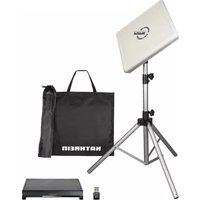
Abb. 1: Sat-Stativ HDS 100

The HDS 100 sat tripod mast is used when there is no "clear line of sight" to the satellite from the location of the caravan or motorhome. There must be no obstructions (bushes, trees, houses etc.) standing in the way of the clear line of sight to the satellite, otherwise good reception cannot be achieved.
■ The sat tripod is suitable for the following types of satellite antenna:
BAS 65 CAS 60 CCA 600
CAS 80 CCA 750
■ For mobile use of satellite antennas
■ Tripod mast of aluminium
■ Maximum height: 150 cm
Scope of supply
- Sat tripod mast
• Securing pegs, quantity 3 - Extension
- Carrying case
• 4 adapter sleeves for mounting the BAS 65 antenna

Fig. 1: Sat tripod mast HDS 100
Select the antenna location

Caution
Risk of injury due to the sat tripod mast with attached satellite antenna and antenna cable (coaxial cable). Trip hazard!
Position the sat tripod mast and lay the antenna cable in such a way that neither you nor anyone else can trip over it or be obstructed or put at risk in any way.
▶ Select a location for the sat tripod mast from which the antenna has a clear line of sight to the satellite.
Installation
A Erect the sat tripod mast
Unfold the sat tripod mast, align it and secure it
- Loosen the star grip screw ① (Fig. 2, P. 2) and fold out the legs ⑤ of the sat tripod mast. To do this, push the joint head ② downwards until the struts ③ are horizontal.
- Tighten the star grip screw and position the sat tripod mast at its chosen location.
- Align the sat tripod mast so that the mast tube ④ is vertical and one of the legs is facing towards the satellite.
4.

Caution
Risk of injury due to the sat tripod mast tipping over in a strong wind. Be sure to drive the securing pegs sufficiently firmly into the ground to provide an anchor.
Secure the sat tripod mast using the securing pegs supplied. Do this by inserting the securing pegs into the ground through the holes in the tripod mast legs Ⓐ (Fig. 1, P. 1).
Prepare the extension
- Loosen the star grip screw © (Fig. 3) and pull the extension Ⓓ out until 2 engagement pin holes are visible.
- Insert the engagement pin Ⓑ sufficiently far into the lower of the two holes until both grooves are engaged with the tube wall.
Fit the antenna and extend the extension to the required height
- Fit the antenna on to the extension. If necessary, request a second person to assist you to hold the antenna steady until it is clamped on to the mast.
Note
To erect the BAS 65 antenna you will need the adapter sleeves supplied. The way to fit these sleeves is described in Fig. 5, P. 3.
8.

Warning
Risk of injury due to pulling the extension right out of the mast tube. Pull the extension out of the mast tube no higher than the point where the 5th engagement pin hole is just visible and the extension projects no more than a maximum of 62 cm out of the mast tube.
With the antenna mounted, use one hand to pull out the extension to the desired height, taking care not to exceed the maximum height.
- With the other hand, insert the engagement pin sufficiently far into the engagement pin hole for the desired height, until both grooves are engaged with the tube wall (Fig. 4).
- Allow the extension to slowly slide down into the mast tube until the engagement pin rests on the top of the tube.
- Align the antenna towards the satellite and tighten the star grip screw © a little.

Fig. 2: Mast tube and legs

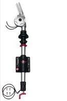
Fig. 3: Mast tube and extension

Fig. 4: Correct position of the engagement pin
B Connect the antenna cable
- Connect the antenna cable to the antenna as described in the user instructions for the antenna.
2.

Caution
Risk of injury due to the antenna cable (coaxial cable). Particular trip hazard in darkness. Lay the antenna cable in such a way that neither you nor anyone else can be obstructed or put at risk.
Lay the antenna cable from the antenna to the receiver.
- Connect the antenna cable to the receiver as described in the user instructions for the receiver.
- Switch the receiver and TV set on and select a channel.
C Adjust the lateral alignment (elevation and azimuth)
Rough adjustment
- Adjust the elevation for your location as described in the user instructions for the antenna.
- Adjust the azimuth as follows:
a) Loosen the star grip screw ©.
b) Turn the antenna to the right or left until a TV picture appears.
c) Tighten the star grip screw a little.
Fine adjustment
- Repeat the adjustment of elevation and azimuth as described under Rough adjustment until the best picture quality is achieved.
- Fully tighten the star grip screw ©.
D Fit the adapter sleeves to the BAS 65 installation clamps

Note the following points when fitting the BAS 65 installation clamps to the sat tripod mast:
▶ Place the 4 adapter sleeves Ⓔ on the threaded rods Ⓕ 2 , as shown in Fig. 5.
1) Included in the scope of supply of the sat tripod mast.
2) Included in the scope of supply of the BAS 65 installation clamps.
Fig. 5: Position the adapter sleeves Ⓔ on the threaded rods Ⓕ.
Removal

Warning
Crush hazard when pushing the tripod mast legs together. When pushing the tripod mast legs together, hold the tripod mast by the mast tube above the joint head.

Caution
Risk of injury due to the sat tripod mast with the antenna fitted tipping over. If necessary, request a second person to assist you if, contrary to these instructions, you fold up the sat tripod mast with the antenna still attached.
- Loosen the star grip screw © and slightly lift up the extension Ⓓ with the attached antenna.
- With the other hand, remove the engagement pin ® from the extension, and insert it into the 2nd engagement pin hole from the top.
- Allow the extension to slowly slide down into the mast tube until the engagement pin rests on the top of the tube.
- Remove the antenna. If necessary, request a second person to assist you to hold the antenna steady whilst you remove it from the mast.
- Perform steps 1 to 8 (P. 1f) in the reverse sequence (remove the engagement pin – slide the extension in – fold in the legs).
Technical data
Type Unit Value
| Dimensions | ||
| packaged (H x W x D) | mm | 145 x 135 x 810 |
| erected | ||
| Height | mm | 1500 max. |
| Stand diameter | mm | 1200 max. |
| Tube diameter | mm | 35 |
| Weight | ||
| Tripod | kg | 2.4 |
| Total | kg | 3.3 |
Note
The latest version of these user instructions can be found at the Kathrein homepage under www.kathrein.com → Satellite and Terrestrial Reception Systems → Product Overview → Camping/caravan reception systems → Accessories. The user instructions are available for download at the HDS 100 product page.

Electronic equipment is not household waste! In accordance with directive 2002/96/EC OF THE EUROPEAN PARLIAMENT AND THE COUNCIL dated 27th January 2003 on used electrical and electronic equipment, it must be disposed of properly.
At the end of its service life, take this device for disposal at a designated public collection point.
936.4856/-/VMWI/1114/GB - Technical data subject to change.
KATHREIN-Werke KG • Anton-Kathrein-Strasse 1 – 3 • Postfach 100 444 • 83004 Rosenheim • Germany • Telephone +49 8031 184-0 • Fax +49 8031 184-306


- SCOPE OF SUPPLY
- SELECT THE ANTENNA LOCATION
- CAUTION
- INSTALLATION
- A ERECT THE SAT TRIPOD MAST
- PREPARE THE EXTENSION
- NOTE
- WARNING
- B CONNECT THE ANTENNA CABLE
- C ADJUST THE LATERAL ALIGNMENT (ELEVATION AND AZIMUTH)
- ROUGH ADJUSTMENT
- FINE ADJUSTMENT
- D FIT THE ADAPTER SLEEVES TO THE BAS 65 INSTALLATION CLAMPS
- NOTE THE FOLLOWING POINTS WHEN FITTING THE BAS 65 INSTALLATION CLAMPS TO THE SAT TRIPOD MAST
- REMOVAL
- TECHNICAL DATA
Brand : KATHREIN
Model : HDS 100
Category : Satellite receiver