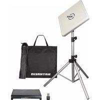
HDS 166 plus - Satellite receiver KATHREIN - Free user manual and instructions
Find the device manual for free HDS 166 plus KATHREIN in PDF.


| Product Type | Satellite Receiver |
| Brand | Kathrein |
| Model | HDS 166 plus |
| Dimensions (W x H x D) | 300 mm x 50 mm x 200 mm |
| Weight | 1.2 kg |
| Power Supply | 12V DC, 1.0 A |
| Power Consumption | 10 W (max) |
| Video Decoding | MPEG-2 / MPEG-4 (H.264) |
| Video Resolution | 1080p (Full HD) |
| Audio Decoding | MPEG-1 Layer I/II, Dolby Digital |
| Satellite Standard | DVB-S / DVB-S2 |
| Input Frequency | 950 – 2150 MHz |
| Input Level | -25 to -65 dBm |
| LNB Power | 13/18 V, 500 mA max |
| DiSEqC Support | DiSEqC 1.0, 1.2 |
| Output Ports | HDMI, SCART, RCA Audio/Video, USB 2.0, Ethernet |
| Channel Memory | 5000 channels |
| Electronic Program Guide (EPG) | Yes (up to 7 days) |
| Parental Control | Yes (PIN-protected) |
| Maintenance & Cleaning | Wipe with a soft, dry cloth. Do not use liquid cleaners. |
| Safety | Operate in a dry, ventilated area. Do not expose to water or moisture. |
| Spare Parts & Repairability | Remote control and power adapter available from Kathrein service centers. |
| General Information | Designed for reliable reception of free-to-air and encrypted satellite channels. |
Frequently Asked Questions - HDS 166 plus KATHREIN
User questions about HDS 166 plus KATHREIN
0 question about this device. Answer the ones you know or ask your own.
Ask a new question about this device
Download the instructions for your Satellite receiver in PDF format for free! Find your manual HDS 166 plus - KATHREIN and take your electronic device back in hand. On this page are published all the documents necessary for the use of your device. HDS 166 plus by KATHREIN.
USER MANUAL HDS 166 plus KATHREIN
natural_image
Black rectangular electronic device labeled 'KATHREIN' with mounting holes (no additional text or symbols visible)Instruction Manual
Contents
About This Manual....3
Intended Use .... 3
Features 3
Scope of Supply 3
Optional Accessories....4
LCD 89 (order no. 21510004) 4
HDS 50 (order no. 20410070)....4
HDS 42 (order no. 2040000006)....4
HDS 52 (order no. 20410079)....4
UFZ 132 (order no. 204500005)....4
12 V power supply unit 4
Addresses 4
Service and support 4
Service partners....4
Safety Instructions and General Notes......5
Installation and Connection 6
Installing and connecting the CAP converter V2 6
Unpacking and preparations 6
Selecting the installation site 7
Important notes for installation....8
Installing the CAP converter 8
Installing the CAP Converter on the rear panel of a TV set 9
Connecting the CAP converter 10
Functional instructions for connection to the on-board power supply 10
12V battery wiring diagram....10
Connection example CAP x50 GPS 11
Connection example HDS 166 PLUS 11
Connection example CAP 500M plus 12
Operating the CAP Converter with CAP Systems or HDS 166 plus/CAP 500M plus.... 12
External pushbutton....12
Further operating functions 12
Moving the CAP system out of the park position 12
Moving the CAP system to the park position 12
Resetting the CAP system....12
CAP 500M plus/HDS 166 plus....12
CAPcontrol app....12
Software Update 13
Updating the channel list 13
Preparing a software update....13
Performing a software update....13
LED Status Display on the CAP Converter V2/External Pushbutton 14
Technical Data and Dimensions 15
Technical data....15
Dimensions....15
Important Information 16
Disposal 16
About This Manual
This document is part of the product.
▶ Read the instruction manual before using the control unit for the first time.
▶ Perform all operating steps described in the manual in the specified sequence.
For the most up-to-date version of this document, go to www.kathrein-ds.com.

Keep this manual in a safe place for future reference and enclose it with the unit when passing it on to the next user.
Intended Use
The CAP converter V2 control unit is used to control the fully and semi-automatic Kathrein camping satellite systems.
The control unit is designed for use on stationary caravans or motor homes.
Any other use will invalidate the warranty or guarantee.
The following circumstances will result in the loss of all warranty and liability claims towards the manufacturer:
■ Improper installation
■ Use of non-specified mounting materials which cannot guarantee the safety of the control unit
■ Opening the control unit improperly or by force
■ Failure to observe the installation and safety instructions in this manual
Features
■ Easy installation
■ Control unit for the following Kathrein satellite systems: CAP 650 GPS, CAP 750 GPS, CAP 850 GPS, CAP 500M plus (fully automatic) and HDS 166 plus (semi automatic)
■ Streaming of live TV/radio with UFZ 131/UFZ 132 WiFi/USB adapter and free CAPcontrol app
■ Software update via satellite
■ Low power consumption
Scope of Supply
■ Control unit CAP converter V2
■ 12 V connection cable
■ Pushbutton
■ Instruction manual
Optional Accessories
LCD 89 (order no. 21510004)
Always use the supplied extension cable to extend the coaxial cables. If the supplied extension cable is not long enough, use the LCD 89 antenna cable from KATHREIN Digital Systems or a comparable coaxial cable.
Always make sure that the coaxial cables are connected properly. We recommend using the EMU 03 adapter (order no. 273246) from KATHREIN Digital Systems.
HDS 50 (order no. 20410070)
The external HDS 50 control panel enables you to operate the turntables easily and conveniently without having to switch on a receiver or TV set. Selecting a satellite, lowering the turntable to the park position and other functions can be called up via an intuitively structured menu. An LC display provides the necessary overview.
HDS 42 (order no. 2040000006)
The HDS 42 switches from a receiver-independent CAP turntable to the HDS 166/CAP 500M antenna set or a satellite signal supplied by the campsite. It automatically passes on the received satellite signal without having to reconnect the coaxial cable on the TV set.
HDS 52 (order no. 20410079)
The CI-BUS adapter enables operation of the Kathrein satellite antenna system (CAP series) using the vehicle-specific control panel of a motorhome/caravan. Please contact your vehicle manufacturer for further information.
UFZ 132 (order no. 204500005)
Use the UFZ 131/UFZ 132 WiFi/USB adapter, in conjunction with the free CAPcontrol app, to make settings on your turntable and control unit and to play live TV/radio on your mobile device (smart-phone, tablet, notebook). The WiFi/USB adapter is plugged into the CAP converter.
12 V power supply unit
For connection to 230 V sockets. This unit requires an adapter cable (order no. 197500004). You can order the plug-in power supply unit and the adapter cable from our service and repair centre:
Factory repair centre
Bahnhofstr. 110
83224 Grassau, Germany
Phone: +49 8641 69984-27
Internet: http://www.css-grassau.de



Addresses
Service and support
Customer support
Eiselauer Weg 13
89081 Ulm, Germany
Phone: +49 731 270 909 70
Email: support@kathrein-ds.com
Business hours:
83224 Grassau, Germany
Phone: +49 8641 699 84 27
Email: service@css-grassau.de
Service partners
Service partners can be found at:
https://www.kathrein-ds.com/support/servicestellen/
Safety Instructions and General Notes

WARNING
Danger to life due to electric current and resulting fire hazard. Observe the following precautions:
12 V connection (vehicle power supply)
▶ Make sure that the 12 V connection cable (power supply cable) is not reversed or damaged during installation.
▶ Make sure that the power supply unit (power supply cable) is not damaged or does not become damaged.
▶ Devices with a damaged power supply unit must be disconnected from the mains (pull the mains plug!) and repaired by an electrical specialist before being used again.
Power supply unit
Mains voltage
▶ Operate the device only at the specified mains voltage. The mains voltage is indicated on the rear of the device and on the power supply unit.
▶ Connect the device to the turntable and the TV set or the cable network and the PC before connecting it to the mains and switching it on.
Accessibility of the mains socket
Place the device close to an easily accessible mains socket so that you can switch off the power at any time if required.

Playing children
▶ Make sure that children do not insert any objects into the ventilation slots.
Cleaning
▶ Unplug the connection cable/power supply unit before cleaning the unit.
▶ Do not, by any means, open the device.
▶ Do not insert any objects into the ventilation slots.
▶ Use a dry cloth for cleaning.
▶ Restrict cleaning to the outer surface of the device.
Ambient conditions
The CAP converter and the power supply unit are for indoor use only.
▶ Protect the device from moisture, dripping and splash water.
▶ Do not operate the device in damp areas.
▶ Only use the device in a moderate climate, not in tropical conditions.
▶ Do not place any liquid-filled objects (such as vases) on top of the device.

Overheating
Observe the following precautions, so that the heat generated in the device is adequately dissipated.
▶ Unless otherwise specified in the supplied manual, maintain the following clearances around the device: 20 cm above, 2 cm to the side and 5 cm to the front and back.
▶ Never cover or block the ventilation slots or the fan of the device, e.g. with other equipment, magazines, tablecloths, clothing or curtains.
▶ Do not place any objects on top of the device.
▶ Do not place the device near a heater. Do not place naked flames, such as candles, on the device.
▶ Do not expose the device to direct sunlight.

Effects of waste heat from the device
▶ Every electronic device generates heat. The temperature rise of the device lies within the permissible range. Sensitive furniture surfaces and veneers may, however, discolour over time due to constant exposure to heat.
The feet of the device may cause colour changes on treated furniture surfaces. To avoid possible discolouration, place the device on a suitable firm and level surface.

Incorrect wiring of the connections
Incorrect wiring of the connections may lead to malfunctions or defects in the device.
There is a risk of data loss and software damage if the CAP converter is disconnected from the mains during operation.
Always wait until the control unit is in standby mode before disconnecting it from the vehicle power supply or mains. This ensures that any new or changed data will be saved by the control unit.
Prolonged absence or thunderstorms
In case of prolonged absence or thunderstorms, always switch off the device (from standby mode) at the mains switch.
How to use this manual
▶ Read the instructions carefully before setting up the device.
▶ Keep the manual for future reference, and pass it on to any new owner.
Updates
The information in this manual was correct at the time of going to press. However, we reserve the right to make changes at any time without prior notice. If new software which affects the information in this manual (e.g. changes to functions) is released for your CAP converter V2, we will, if we consider it necessary, provide a new manual for download at www.kathrein-ds.com.
Repair
Make sure that any repairs to the device are carried out by qualified personnel only.
▶ Improper work on the device may impair its electrical safety.
The manufacturer accepts no liability for accidents caused by the user opening the unit.
▶ Unauthorised opening and repair attempts will render all warranties invalid.
Installation and Connection
Installing and connecting the CAP converter V2
Unpacking and preparations

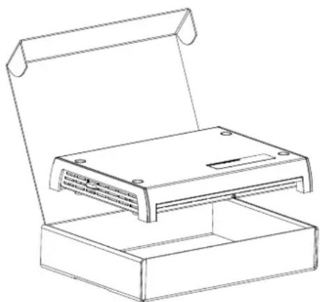
The packaging of the CAP converter can be opened at the front. The converter is packed in an antistatic fleece; remove this fleece.
▶ Keep the original packaging. If it is necessary to send the CAP converter for repair, use the original packaging to prevent transport damage. The manufacturer accepts no liability for possible damage.
natural_image
Line drawing of a rectangular electronic device with a lid and base, no text or symbols presentSelecting the installation site

When choosing the installation place, bear in mind that the rear of the CAP converter should always be accessible. The CAP converter is equipped with a power saving circuit, which means that the unit does not need to be placed where it is visible. This allows you to install the CAP converter out of sight in any position, e.g. on cabinet walls, side panels or storage shelves.
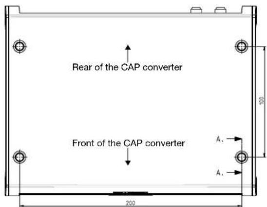
The four screw holes make it possible to place the CAP converter on a firm horizontal surface but also to screw it on in any desired position.
When choosing the installation place, observe the following:
- The wall thickness of the installation surface must be at least 15 mm, otherwise the screws will come out the back or damage the surface.
- The cabinet or storage compartment in which the device is to be installed must be sufficiently ventilated to prevent heat accumulation. Carpet-covered walls are unsuitable for installation.
- When screwing in the screws, do not damage any cables or similar that are routed behind or in the installation wall.
- The CAP converter is exclusively intended for installation in dry indoor areas.
- The cable lengths must be taken into account when choosing the installation place.
- Strain-relieve the connecting cables.
Connections and fuses
All connecting cables are connected to the rear of the CAP converter. Viewed from the front, there is a fuse inserted from the outside on the left side of the CAP converter. This fuse must also be accessible after installation of the CAP converter so that it can be easily replaced if necessary. For more information about the type of fuse, see the sticker on the CAP converter and the fuse itself.
Ventilation
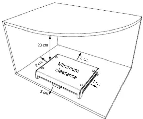
The heat generated in the CAP converter is dissipated on all sides of the housing. When selecting the installation place, make sure that these sides are not obstructed or covered. If the device is permanently insufficiently ventilated, this may have a negative effect on the service life of the device!
Maintain a clearance of at least 20 cm above/below, 2 cm to each side and 5 cm behind and in front of the device to allow unobstructed heat dissipation.

Material damage to the device during operation due to insufficient ventilation!
The operating temperature is measured by the device. Continuous operation at temperatures higher than the recommended operating temperature may cause premature failure of the device as a result of insufficient ventilation. This is not a warranty or guarantee case!
The CAP converter may only be operated at the recommended operating temperature.
Important notes for installation

Danger to life due to high voltage!
Wood screws may come into contact with live parts and cause danger to life from electric shock.
▶ Never use the wood screws supplied with the CAP converter to install the CAP converter on another electrical appliance (e.g. TV set).

Material damage to the device due to countersunk screws!
▶ Never use countersunk screws for installation.
▶ Use the wood screws supplied with the CAP converter.


Material damage to the device and malfunction due to overheating!
If the CAP converter is installed on another electrical device (e.g. TV set), the mutual heating may lead to overheating.
Before installing the CAP converter on another electrical device, ask the manufacturer of the device or refer to the documentation supplied with the device to find out whether this is permissible and, if so, which aids (screws etc.) are required/may be used.
Using other screws
If the supplied screws cannot be used due to the installation place or the condition of the installation place, please refer to the figure on the right to select the correct screws. It shows a cross-section of the screw holes of the CAP converter. It also specifies the required characteristics of the fixing screws which are inserted into the bracket of the CAP converter, e.g. diameter, type of screw head, etc.

Installing the CAP converter
The distances of the drilling points can be seen in the diagram below.

Material damage to the device by overtightening the screws!
If you apply too much force when tightening the screws, you may damage the screw holes and the housing of the CAP converter or any cables already connected to it.
▶ Tighten the screws carefully.
Installation on a wooden surface:

natural_image
Technical line drawing of a device casing with screw holes and mounting brackets (no text or symbols)
Installing the CAP Converter on the rear panel of a TV set

Danger to life due to high voltage!
Screws that are screwed in too deeply may damage the TV set beyond repair and cause danger to life through electric shock.
▶ Before starting any installation work, disconnect all units from the mains.
Before installing the CAP converter, check with the manufacturer of the device or in the documentation supplied with it whether this is permissible, and if so, what aids (screws, etc.) are necessary or can be used.

Material damage and risk of injuries due to overheating of the devices and fire!
▶ Do not install the CAP converter between a TV set and a wall bracket.
The CAP converter may only be installed on the rear panel of a TV set if the TV has a stand which is also firmly mounted.
Only two screws are required to secure the CAP converter to the rear panel of the TV set. Before installing the CAP converter, note the following:
- The TV set must have one of the following hole patterns for wall mounting on its rear panel: 100 x 100; 100 x 200; 200 x 200 or 200 x 400. If this is not the case, a VESA adaptor plate can be obtained from a specialist dealer.
- Before mounting the CAP converter, read the chapter on wall mounting in the operating manual of your TV set to find out about the screw diameter (M4, M6 or M8) and the permitted screw-in depth.
Connecting the CAP converter

The CAP converter V2 may only be operated with a supply voltage of 10.5 to 30.0 V. The earth connection of the CAP converter must be connected to the negative pole of the motor home or caravan battery. Disconnect the vehicle electrical system (main switch "Off" or disconnect the positive pole from the vehicle electrical system battery) before starting the following work.
- Connect the master coaxial cable (of the turntable) or coaxial cable (of the HDS 166 plus/CAP 500M plus) to the F socket "Antenna" on the back of the CAP converter.
- Connect the "TV/STB" connection of the CAP converter and a receiver or TV set with integrated satellite tuner using a coaxial cable.
- Connect the supplied power cable (depending on the power supply available in your motor home or caravan, 12 V or 230 V with mains adapter) to the "12V 2.0A" plug-in connection of the CAP converter.
- Check the connections before you reconnect the on-board power supply.
Connections on the CAP converter

① TV / STB Output satellite signal to TV/receiver
② ANTENNA Input satellite signal of Kathrein CAP/HDS
③ RESET Reset button
④ USB 2.0 Type A USB port
⑤ ETHERNET RJ45 network socket
⑥ CONTROL UNIT Connection to pushbutton//HDS 50/HDS 52 RJ 12
⑦ STATUS Status LED to indicate the operating status
⑧ Power switch
⑨ 12V 2.0A Power supply
Functional instructions for connection to the on-board power supply
Problems may occur if the devices are connected to different connection sockets or circuits/earth potentials. It is recommended to connect the connection sockets of the turntable to the same cable. Check the current carrying capacity of the circuit used to ensure compliance with the intended application.
12V battery wiring diagram

The CAP converter must be protected by a 5 A fuse, which is to be connected between the red connection cable and the battery.
Connection example CAP x50 GPS

flowchart
graph TD
    A["TV set 1 with satellite tuner"] --> B["TV set 2 with satellite tuner"]
    B --> C["Slave coaxial cable"]
    C --> D["Master coaxial cable"]
    D --> E["Power supply cable"]
    E --> F["Cap Converter control unit"]
    F --> G["HDS 50* separate control panel"]
    F --> H["CAPcontrol app* control & streaming"]
    I["TV set 1 with satellite tuner"] --> J["Ignition"]
    J --> K["12V"]
    K --> L["Satellite monitor with Wi-Fi Hotspot"]
    M["UFZ 132* Wi-Fi Hotspot"] --> N["Satellite monitor with Wi-Fi Hotspot"]
*) Optional accessories
Connection example HDS 166 PLUS

Connection example CAP 500M plus

flowchart
graph TD
    A["USB/WiFi adapter<br>WiFi hotspot"] --> B["CAP Converter V2<br>Control unit"]
    B --> C["TV set<br>with satellite tuner"]
    D["EV 06<br>Outdoor F-type outlet"] --> E["CAPcontrol app<br>Streaming of live TV"]
    E --> F["KATHREIN"]
    B --> G["TV set with satellite tuner"]
    G --> H["CAP 500M plus<br>Fully automatic, portable system"]
Operating the CAP Converter with CAP Systems or HDS 166 plus/CAP 500M plus
External pushbutton
Plug the external Kathrein pushbutton included in the scope of supply into the RJ12 socket CONTROL UNIT ⑥ on the CAP converter V2 (see Connecting the CAP converter, p. 10).
The CAP converter V2 automatically goes into standby if no action is performed for 10 minutes (duration adjustable via CAPcontrol app). If the CAP converter V2 is in standby, the LED on the external button lights up red continuously. Pressing the button switches the control unit on again. In the event of an error, the error can be confirmed by pressing the external button (see "Error" LED Status Display on the CAP Converter V2/External Pushbutton, p. 14).
Further operating functions
Moving the CAP system out of the park position
Press the pushbutton
▶ The turntable moves to the last satellite position
Moving the CAP system to the park position
Press the pushbutton
▶ The turntable moves to the park position
Resetting the CAP system
Keep the pushbutton pressed for 5 seconds
The turntable is reset. The LED flashes 3x green and 1x red until the turntable is in park position
CAP 500M plus/HDS 166 plus
Press the button
▶ Error confirmation
▶ Status display
▶ Exiting the standby mode
CAPcontrol app
The UFZ 131 or UFZ 132 WiFi/USB adapter (optional accessory) is required to control the CAP systems or the HDS 166 plus or CAP 500M plus via the CAPcontrol app. Plug the adapter into the USB port ④ of the CAP converter (see Connecting the CAP converter, p. 10).
Then download the CAPcontrol app from the Play Store (Android) or App Store (iOS) and install it on your mobile device. The exact functionality of the app can be found in the app user guide.
Software Update
Updating the channel list
√ A FAT32-formatted USB stick is available for this task.
- On the USB stick, create the folder "kathrein" with the subfolder "capconverter".
- Download the channel.xml file with the current channel list from https://www.kathrein-ds.com/support/downloadbereich/
- On the USB stick, save the channel.xml file in the subfolder "capconverter".
- Plug the USB stick into the USB port of the CAP converter and switch off the CAP converter at the power switch.
- Switch the CAP converter on again.
→ The channel list is loaded automatically when the CAP converter is switched on. The LED status indicates whether the channel list has been loaded successfully or whether a problem has occurred, see LED status display.
Preparing a software update
√ A FAT32-formatted USB stick is available.
- Download a country-specific zip file, e.g. "CAP-Konverter_Deutschland_08.19.zip" from https://www.kathrein-ds.com/support/downloadbereich/
- Open the downloaded zip file with a double click and execute the exe file with a double click.
- Click on the “...” button to select the FAT32-formatted USB stick that you want to use for the update.
- Confirm the selection with "OK".
- Click on the "Extract" button.
⇒ The required files are automatically unpacked to the corresponding folder structure on the USB stick.
Performing a software update
- Switch off the CAP converter at the power switch.
- Plug the USB stick into the USB port of the CAP converter.
- Keep the "Reset" button on the back of the CAP converter pressed and simultaneously switch on the CAP converter at the power switch.
→ During the update process the LED starts to light up yellow.
- Release the "Reset" button.
⇒ The update process lasts about 90 seconds. The successful update is indicated by fast "red-green-yellow" flashing. An error during the update is indicated by red flashing (see LED Status Display on the CAP Converter V2/External Pushbutton, p. 14).
- After a successful update, switch off the CAP converter at the power switch, remove the USB stick and restart the CAP converter.

The update only works if the reset button on the back of the CAP converter is pressed!
LED Status Display on the CAP Converter V2/External Pushbutton
| Function | LED Colour Signal | Description | |
| Error Red | LED flashes 1x for 0.5 sec, then pauses for 2 sec No connection to CAP/HDS | ||
| LED flashes 2x for 0.5 sec, then pauses for 2 sec Satellite not found | |||
| LED flashes 3x for 0.5 sec, then pauses for 2 sec Ignition is active | |||
| LED flashes 4x for 0.5 sec, then pauses for 2 sec Turntable is blocked | |||
| LED flashes 5x for 0.5 sec, then pauses for 2 sec Operating voltage too low | |||
| LED flashes 6x for 0.5 sec, then pauses for 2 sec Temperature warning | |||
| LED flashes 7x for 0.5 sec, then pauses for 2 sec Channel list incorrect | |||
| LED flashes 8x for 0.5 sec, then pauses for 2 sec CAP software not up to date | |||
| LED flashes 9x for 0.5 sec, then pauses for 2 sec CAP requires calibration | |||

To return the CAP converter to normal operation:
- Check the cause of error.
- Press the pushbutton once to acknowledge the error so that the CAP converter can return to normal operation.
| Normal operation | Green | LED flashes slowly CAP is in the park position | |
| LED flashes 3x, followed by a short pause | CAP is moving to the park position. | ||
| LED flashes quickly | CAP is searching for a satellite signal | ||
| LED is permanently on Satellite found | |||
| Red LED is permanently on Standby | |||
| Green-red LED flashes quickly 3x green and 1x red | CAP is reset and moves to the park position | ||
| USB update | Yellow ^1) | LED is permanently on Downloading data from USB | |
| Red-green-yellow | LED flashes quickly Update successful | ||
| Red | LED flashes 1x for 0.5 sec, then pauses for 1.5 sec | Data carrier not found | |
| LED flashes 2x for 0.5 sec, then pauses for 1.5 sec | Folder structure/update file not found | ||
| LED flashes 3x for 0.5 sec, then pauses for 1.5 sec | Invalid update file | ||
| LED flashes 4x for 0.5 sec, then pauses for 1.5 sec | Saving update file failed |
^1) The red and the green LED on the external pushbutton light up simultaneously.
Technical Data and Dimensions
Technical data
| Type / Order No. | CAP Converter V2204500001 | |
| Colour Black | ||
| Sat IF band MHz 950-2150 | ||
| Input level range dBμV 44-83 | ||
| Modulation, FEC, demultiplexer DVB-S(2) | ||
| Input data rate MSymb/s 2-45 (30 for DVB-S2/8PSK) | ||
| Supply voltage (vehicle battery) V 10.5-30.0 | ||
| Power consumption at 230 V(max./typical operation/standby) | W 14 / 12 / 0.2 | |
| LNB supply (horiz./vert.) V/mA 14 / 18; max. 400 | ||
| Antenna 1 x F-type connector | ||
| TV/STB 1 x F-type connector | ||
| Supported control signals (TV input) | DiSEqCTM1.0 / 22 kHz; 14/18 V | |
| USB | 1 x 2.0 | |
| Ethernet | 1 x RJ45 | |
| Control unit | 1 x RJ12 | |
| Permissible ambient temperature | °C | -10 to +45 |
| Weight | kg | 0.5 |
Dimensions

Important Information

Satellite configuration in the CAP converter
The CAP converter allows 4 satellite positions to be selected directly via a connected satellite receiver or TV set ^1 . To do so, the sequence of the satellite positions in the receiver/TV set and in the CAP converter must match.
The CAP converter has the following default settings for satellite positions:
• Satellite 1: Astra 19.2°E
• Satellite 2: Hotbird 13°E
- Satellite 3: Astra 23.5^
• Satellite 4: Astra 28.2°E
Satellite settings in the CAP converter
The satellite positions in the CAP converter can be changed as follows:
- Via the free CAPcontrol app (available for Android and iOS)
To change the satellite position, open the app and go to "Settings > Satellite selection". To use the app, you will either need a LAN connection to the router or the UFZ 131/132 ^2 WiFi/USB adapter with wireless hotspot function.
• Via the HDS 50external control panel
▶ Enter the desired changes via the setting keys.
- By updating the satellite XML file created on the computer via USB update. Ready-to-use config.xml files are available free of charge at https://www.kathrein-ds.com/support/downloadbereich/ or from our service centre in Ulm.
-
On a USB stick, create the folder "kathrein" with the subfolder "capconverter" (use lower case for the folder name).
-
Copy the config.xml file to the capconverter subfolder.
-
Plug the USB stick into the switched-on CAP converter.
-
The config.xml file is installed automatically.
- During installation, the yellow LED lights up. After successful installation, the green and then the yellow LED lights up for 1 second each.
- If the installation failed, the red and then the yellow LED lights up for 1 second each. Check the folder structure. Make sure that the folder names are written in lower case letters.
For information on setting the satellite positions of your receivers, please refer to the operating instructions or contact the hotline of the respective equipment manufacturers.
^1) TV with a integrated satellite receiver
2) Available as accessory
Disposal

Electronic equipment
Electronic equipment is not domestic waste – in accordance with directive 2012/19/EC OF THE EUROPEAN PARLIAMENT AND THE COUNCIL dated 04th July 2012 concerning used electrical and electronic appliances, it must be disposed of properly. At the end of its service life, take the unit to a designated public collection point for disposal.


- Contents
- About This Manual
- Intended Use
- Any other use will invalidate the warranty or guarantee.
- Features
- Scope of Supply
- Optional Accessories
- LCD 89 (order no. 21510004)
- HDS 50 (order no. 20410070)
- HDS 42 (order no. 2040000006)
- HDS 52 (order no. 20410079)
- UFZ 132 (order no. 204500005)
- V power supply unit
- Addresses
- Service and support
- Service partners
- Safety Instructions and General Notes
- WARNING
- Danger to life due to electric current and resulting fire hazard. Observe the following precautions:
- V connection (vehicle power supply)
- Power supply unit
- Mains voltage
- Accessibility of the mains socket
- Playing children
- Cleaning
- Ambient conditions
- Overheating
- Effects of waste heat from the device
- Incorrect wiring of the connections
- There is a risk of data loss and software damage if the CAP converter is disconnected from the mains during operation.
- Prolonged absence or thunderstorms
- How to use this manual
- Updates
- Repair
- Installation and Connection
- Installing and connecting the CAP converter V2
- Unpacking and preparations
- Selecting the installation site
- Connections and fuses
- Ventilation
- Material damage to the device during operation due to insufficient ventilation!
- Important notes for installation
- Danger to life due to high voltage!
- Material damage to the device due to countersunk screws!
- Material damage to the device and malfunction due to overheating!
- Using other screws
- Installing the CAP converter
- Material damage to the device by overtightening the screws!
- Installing the CAP Converter on the rear panel of a TV set
- Material damage and risk of injuries due to overheating of the devices and fire!
- Connecting the CAP converter
- Connections on the CAP converter
- Functional instructions for connection to the on-board power supply
- 12V battery wiring diagram
- Operating the CAP Converter with CAP Systems or HDS 166 plus/CAP 500M plus
- External pushbutton
- Further operating functions
- Moving the CAP system out of the park position
- Moving the CAP system to the park position
- Resetting the CAP system
- CAP 500M plus/HDS 166 plus
- CAPcontrol app
- Software Update
- Updating the channel list
- Preparing a software update
- Performing a software update
- To return the CAP converter to normal operation:
- Technical Data and Dimensions
- Important Information
- Satellite configuration in the CAP converter
- Satellite settings in the CAP converter
- Disposal
- Electronic equipment
Brand : KATHREIN
Model : HDS 166 plus
Category : Satellite receiver