
MC 4040 - Telephone RCF - Free user manual and instructions
Find the device manual for free MC 4040 RCF in PDF.


| Product Type | Electret Microphone |
| Polar Pattern | Cardioid |
| Frequency Response | 50 Hz – 18 kHz (100 Hz – 18 kHz with high-pass filter) |
| Sensitivity | -54 dB ± 3 dB (0 dB = 1 V/μbar @ 1 kHz, open circuit) |
| Impedance | 60 Ω ± 30% @ 1 kHz |
| Power Supply | 12 V – 52 V Phantom power (balanced microphone cable required) |
| Connector | 5-pin JST (internal) with XLR output |
| Dimensions | ∅ 21 mm × 672 mm |
| Net Weight | 0.2 kg |
| Mounting Options | Table top (drilled hole or surface mount) or microphone floor stand |
| Controls | Push-to-talk (PUSH) and lock (LOCK) switches; high-pass filter switch on bottom |
| Indicator | Red ring lamp lights up when microphone is activated |
| Gooseneck | Flexible gooseneck for easy positioning |
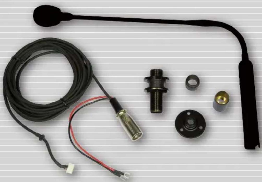
| Included Accessories | Grip adapter, flange, base, rubber pads, screws, washer nut |
| Cleaning | Do not use solvents, alcohol, benzene; wipe with dry cloth |
| Safety | Do not disassemble or modify; use only with Phantom power; contact authorized service for repairs |
| Application | Public address, podium, pulpit, conference tables |
Frequently Asked Questions - MC 4040 RCF
User questions about MC 4040 RCF
0 question about this device. Answer the ones you know or ask your own.
Ask a new question about this device
Download the instructions for your Telephone in PDF format for free! Find your manual MC 4040 - RCF and take your electronic device back in hand. On this page are published all the documents necessary for the use of your device. MC 4040 by RCF.
USER MANUAL MC 4040 RCF
MICROFONO AD ELETTRETE CON FLESSIBILE GOOSENECK ELECTRET MICROPHONE
natural_image
Product photo of a black automotive sensor with attached cable, connector, and housing (no text or symbols visible)User manual Manuale d'uso
INDICE
Important notes page 14
Description page 16
Installation
I. Table top mounting (drilling the table) page 16
II.Table top surface mounting page 18
III. On microphone floor stand page 20
Connections page 21
Use page 21
Specifications ____ page 22
Accessories (included) ____ page 23
IMPORTANTE

CONNETTORE XLR
natural_image
Coiled black cable with red and black connectors, labeled 'CAVO' and 'RON' (no other text or symbols)IMPORTANT NOTES
Before connecting and using this microphone, please read this instruction manual carefully and keep it on hand for future reference. The manual is to be considered an integral part of this product and must accompany it when it changes ownership as a reference for correct installation and use as well as for the safety precautions.
RCF S.p.A. will not assume any responsibility for the incorrect installation and / or use of this product.

SAFETY PRECAUTIONS
- All the precautions (in particular the safety ones) must be read with special attention, as they provide important information.
- Assure all connections have been made correctly before switching all devices on.
- Protect the microphone cable from damage and make sure it is positioned where it cannot be stepped on or crushed by objects.
- Do not put the microphone into water (or another liquid), do not throw it, do not let it fall down.
- Never attempt to carry out any operations, modifications or repairs. If the microphone does not work properly, contact your authorized service centre.
- 'Phantom' power supply needs a balanced microphone cable.
- Should the microphone emit any strange odour or even smoke, turn the sound system off immediately.
- Use dedicated accessories only.
-
RCF S.p.A. strongly recommends the sound system installation is only made by professional qualified installers (or specialised firms), who can certify it according to the regulations in force.
The entire audio system must comply with the current standards and regulations regarding electrical systems. -
There are numerous mechanical and electrical factors to be considered when installing a professional audio system (in addition to those which are strictly acoustic, such as sound pressure, angles of coverage, frequency response, etc.).
- Do not point microphones at near loudspeakers (in order to avoid feedback).
- Hearing loss
Exposure to high sound levels can cause permanent hearing loss. The acoustic pressure level that leads to hearing loss is different from person to person and depends on the duration of exposure. To prevent potentially dangerous exposure to high levels of acoustic pressure, anyone who is exposed to these levels should use adequate protection devices. When a transducer capable of producing high sound levels is being used, it is therefore necessary to wear ear plugs or protective earphones.
- Microphones are to be connected in phase, in order to guarantee a proper sound reproduction, especially when microphones are adjacent one another.
- To prevent inductive effects from causing hum, noise and a bad system working, microphone cables should be shielded, balanced and not be laid together with other electric cables (mains) and loudspeaker lines.
- Keep the microphone far from any excessive heat source. Do not use solvents, alcohol, benzene or other volatile substances for cleaning the external parts.
RCF S.p.A. thanks you for purchasing this product, which has been designed to guarantee reliability and high performances.
DESCRIPTION
It is a slim cardioid electret microphone having a flexible gooseneck.
It offers impressive acoustic features and a mechanical design that is ideal for public address sound systems.
This microphones has two switches (PUSH, LOCK), a red ring lamp that lights up when the microphone is activated, a high-pass filter with a switch to cut frequencies below 100 Hz.
It can be mounted on tables (with or without a hole), podiums, pulpits, etc..
It can be mounted on microphone floor stands too.
It has a built-in ‘Phantom’ power circuit; therefore, it needs to be connected to a mixer microphone input with 12 V ÷ 52 V ‘Phantom’ power supply.
INSTALLATION
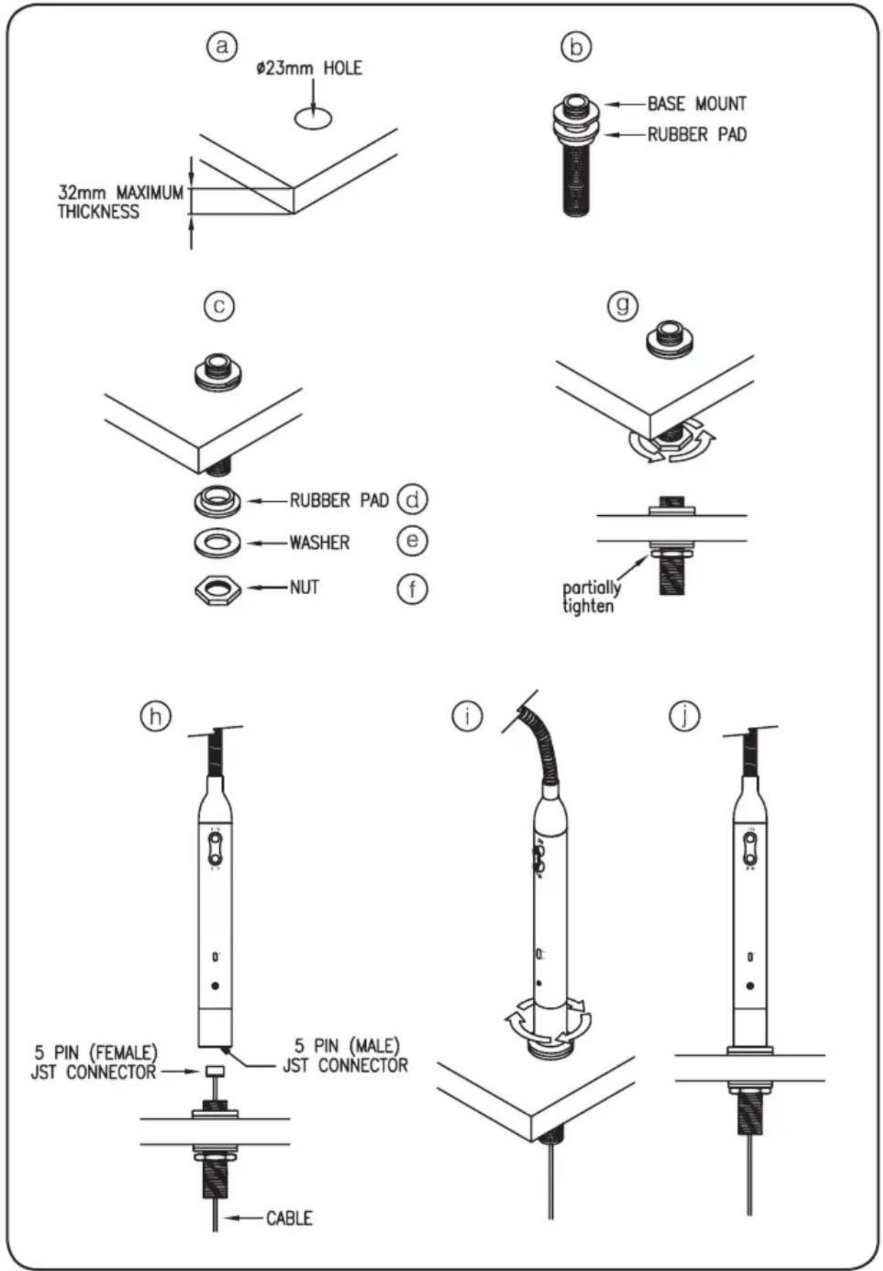
I. TABLE TOP MOUNTING (DRILLING THE TABLE)
a. Drill a 23 mm diameter hole on the desired location (table or podium). The thickness of the mounting surface shall not exceed 32 mm.
b. Insert the longest threaded part of the base into the rubber pad.
c. Insert the base through the drilled hole.
d. Under the table, put the rubber pad into the threaded base.
e. After fixing the rubber pad in place, put the washer into the base.
f. Screw the nut.
g. Tighten the nut partially.
h. Insert the cable through the hole of the base and attach it to the 5 pin JST connector of the microphone (located at the bottom).
i. Screw the microphone to the base.
j. Check the position of the microphone (its switches must face the user). If necessary, adjust again and then tighten the nut.
II. TABLE TOP SURFACE MOUNTING
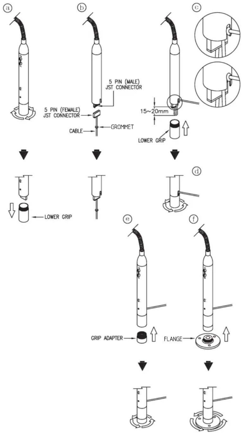
a. Unscrew the lower grip from the microphone.
b. Connect the cable to the microphone 5 pin JST connector (located at the bottom).
c. Bend the cable upwards, 15 \~ 20 mm away from the connector. Arrange the cable with the rubber grommet to the lateral grip exit.
d. Screw back the lower grip to the microphone.
e. Screw the grip adapter to the microphone.
f. Screw the flange to the microphone.
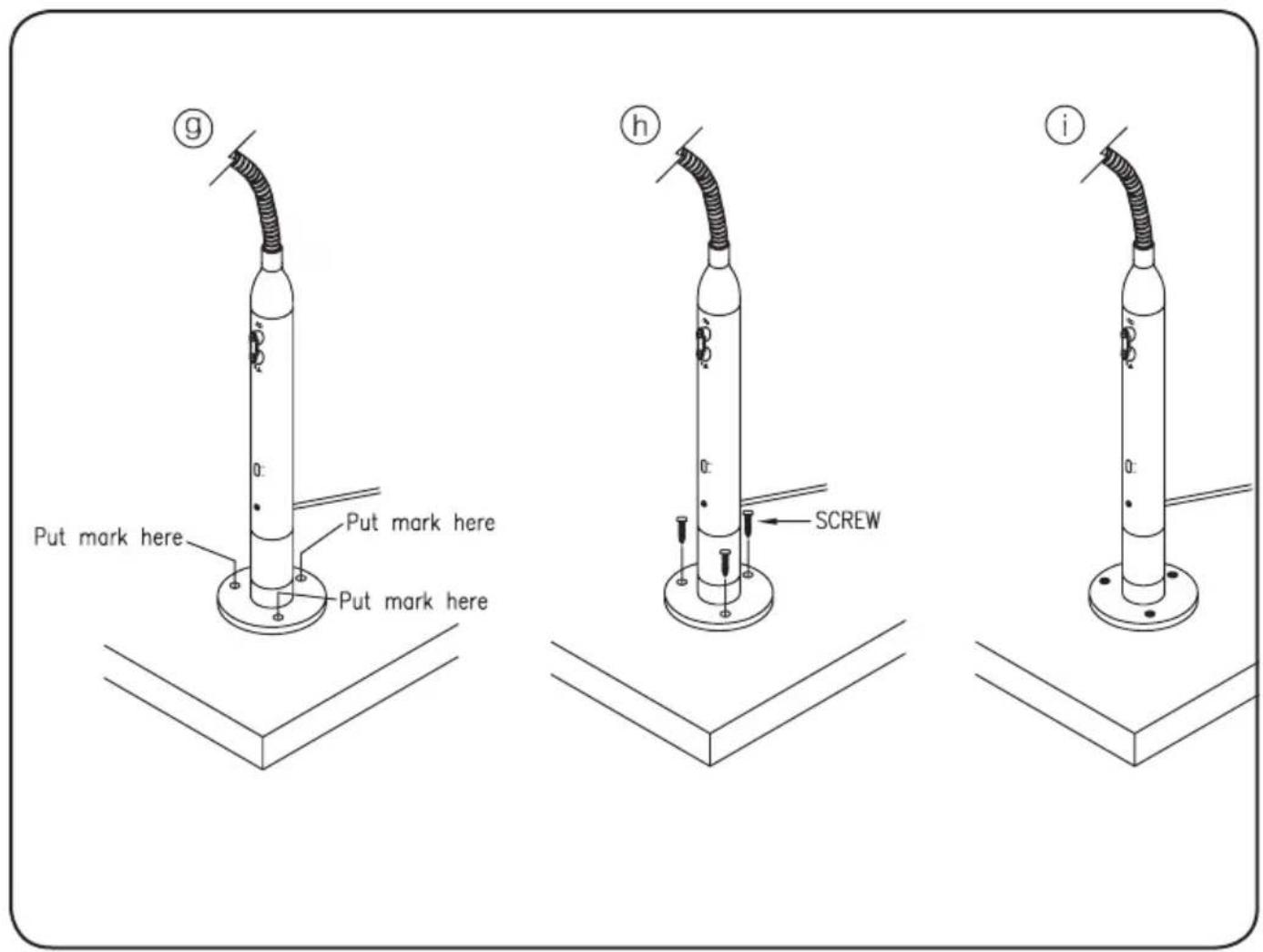
g. Select a desired location of the mounting area, with flat unobstructed surface.
Put the microphone on the surface and then check its position (the microphone switches must face the user). If necessary, mark the surface through the three flange holes.
h. Insert the screws through the flange holes.
i. Tighten the screws to secure the microphone.
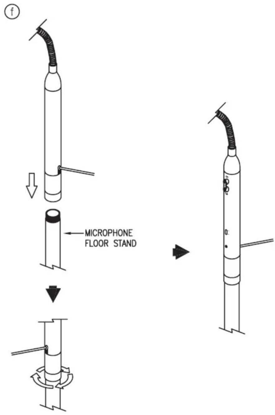
III. ON MICROPHONE FLOOR STAND
a. - e. Repeat procedures (a) to (e) of
'II. TABLE TOP SURFACE MOUNTING'.
- Screw the microphone to the floor stand.
CONNECTIONS
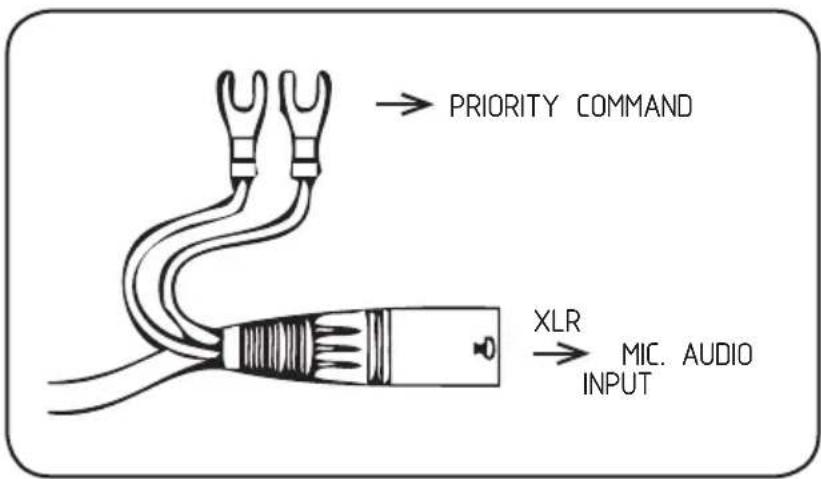
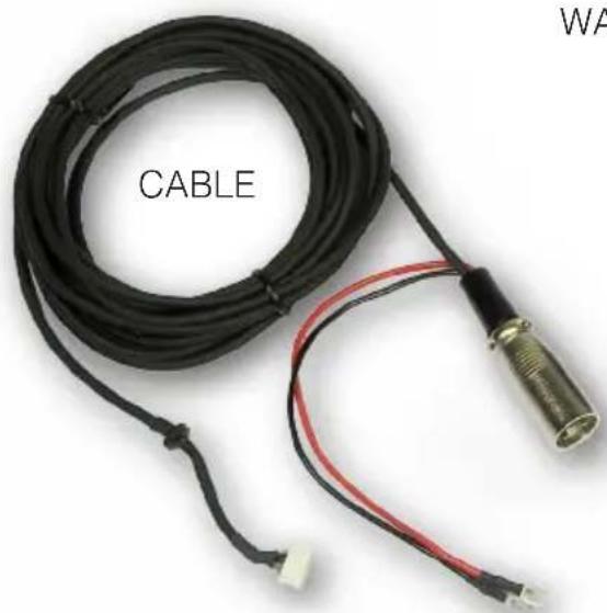
Connect the XLR plug to a mixer microphone input with 'Phantom' power supply.
The two wires can be used as priority command (where this function is foreseen).
XLR CONNECTOR
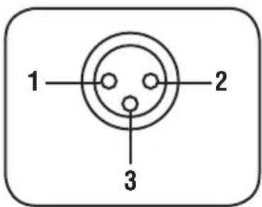
1 - ground
2-hot (+)
3 - cold (-)
USE
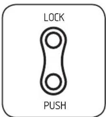
Push the 'LOCK' button once to turn the microphone on; push it again to turn it off.
For a momentary use of the microphone, keep pressing the 'PUSH' button.

The filter switch (on the bottom) has 2 positions:
• high pass √(high-pass filter: on)
- flat_(high-pass filter: off)
The high pass filter can be inserted to limit the low frequency rumble. It can also be useful to cut the low frequencies in places with long reverberation, in order to get a better speech intelligibility.
SPECIFICATIONS
Type: electret microphone
Polar pattern: cardioid
Frequency response: 50 Hz ÷ 18 kHz
(100 Hz ÷ 18 kHz, with high-pass filter)
Sensitivity: -54 dB ± 3 dB
(0 dB = 1 V / μbar 1 kHz, open circuit)
Impedance: 60 Ω ± 30% @ 1 kHz
Power supply voltage: 12 ÷ 52 V 'Phantom' power
Internal plug: 5 pin JST connector
Dimensions: ∅ 21 mm × 672 mm
Net weight: 0.2 kg
ACCESSORIES (INCLUDED)
TABLE TOP SURFACE MOUNTING
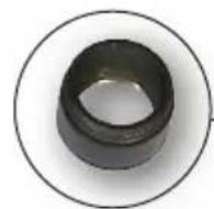
GRIP ADAPTOR
ON MIC.
FLOOR STAND
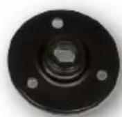
FLANGE
TABLE TOP MOUNTING WITH HOLE
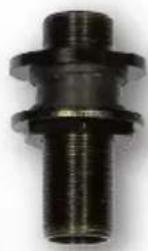
BASE
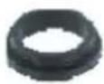
RUBBER PADS
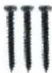
SCREWS
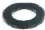
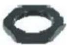
WASHER NUT
natural_image
Coiled black cable with red and black connectors, labeled 'CABLE' (no other text or symbols visible)- MICROFONO AD ELETTRETE CON FLESSIBILE GOOSENECK ELECTRET MICROPHONE
- INDICE
- IMPORTANTE
- CONNETTORE XLR
- IMPORTANT NOTES
- SAFETY PRECAUTIONS
- RCF S.p.A. thanks you for purchasing this product, which has been designed to guarantee reliability and high performances.
- DESCRIPTION
- INSTALLATION
- TABLE TOP MOUNTING (DRILLING THE TABLE)
- TABLE TOP SURFACE MOUNTING
- ON MICROPHONE FLOOR STAND
- CONNECTIONS
- XLR CONNECTOR
- USE
- SPECIFICATIONS
- ACCESSORIES (INCLUDED)
Brand : RCF
Model : MC 4040
Category : Telephone