
AM 1064 - Mixer RCF - Free user manual and instructions
Find the device manual for free AM 1064 RCF in PDF.


| Product Type | Mixer-Amplifier |
| Model | AM 1064 |
| Brand | RCF |
| Maximum Output Power | 60 W |
| Amplifier Type | Analogue |
| Frequency Response | MIC: 60 Hz - 15 kHz; LINE / AUX: 50 Hz - 15 kHz |
| Distortion (at Max Power) | < 1.5% |
| Audio Inputs | 3 MIC/LINE (XLR), 1 AUX (dual RCA), 1 MAIN IN (RCA) |
| Audio Outputs | 100 V / 70 V constant voltage line, 4 Ω low impedance, PRE OUT (RCA) |
| Input Sensitivity | MIC: 1.5 mV (-54 dBu); LINE: 200 mV (-12 dBu); AUX: 200 mV (-12 dBu) |
| Input Impedance | MIC/LINE: 600 Ω (balanced); AUX: 10 kΩ (unbalanced) |
| Phantom Power | Input 1: > 18 V DC, max 20 mA |
| Priority Function | Input 1: via contact closure or VOX (automatic) |
| Tone Controls | Bass and Treble |
| LED Indicators | Power on (blue), Signal level (green -20 dB, orange -9 dB, red 0 dB peak) |
| Power Supply | 115 V / 230 V ~, selectable; Max consumption: 170 W |
| Dimensions (W x H x D) | 431 mm x 88 mm x 385 mm (19" rack, 2U) |
| Net Weight | 10 kg |
| Operating Temperature | -10 °C to +45 °C (+14 °F to +113 °F) |
| Safety Class | Class I (protective earthing) |
| Fuse Rating (230 V / 115 V) | T1.6AL 250V / T3AL 250V |
| Installation | 19" rack mount (included rack ears); use ventilation panels |
| Maintenance | Clean with dry cloth; do not use solvents, alcohol, benzene |
| Repairability | Contact authorized service centre for internal adjustments (e.g., JP1 jumper) |
Frequently Asked Questions - AM 1064 RCF
User questions about AM 1064 RCF
0 question about this device. Answer the ones you know or ask your own.
Ask a new question about this device
Download the instructions for your Mixer in PDF format for free! Find your manual AM 1064 - RCF and take your electronic device back in hand. On this page are published all the documents necessary for the use of your device. AM 1064 by RCF.
USER MANUAL AM 1064 RCF
OWNER MANUAL MANUALE D'USO
AM 1064 AM 1125
- MIXER-AMPLIFIERS
- MIXER-AMPLIFICATORI
INDEX INDICE

ENGLISH
SAFETY PRECAUTIONS 4
DESCRIPTION 6
INSTALLATION INTO 19" RACK CABINETS | 7
FRONT PANEL 7
REAR PANEL 8
LOUDSPEAKER CONNECTION 11
SPECIFICATIONS 12
USE EXAMPLE 12
ITALIANO
AVVERTENZEPERLASICUREZZA 14
DESCRIZIONE 16
Before connecting and using this product, please read this instruction manual carefully and keep it on hand for future reference.
The manual is to be considered an integral part of this product and must accompany it when it changes ownership as a reference for correct installation and use as well as for the safety precautions.
RCF S.p.A. will not assume any responsibility for the incorrect installation and / or use of this product.
WARNING: To prevent the risk of fire or electric shock, never expose this product to rain or humidity.
SAFETY PRECAUTIONS
- All the precautions, in particular the safety ones, must be read with special attention, as they provide important information.
2.1 PRIMARY POWER SUPPLY FROM MAINS
- The mains voltage is sufficiently high to involve a risk of electrocution: never install or connect this product when its power cord is plugged in.
- Before powering up, make sure that all the connections have been made correctly and the voltage of your mains corresponds to the voltage shown on the rating plate on the unit, if not, please contact your RCF dealer.
- The metallic parts of the unit are earthed by means of the power cord.
- An apparatus with CLASS I construction shall be connected to a mains socket outlet with a protective earthing connection.
- Protect the power cord from damage. Make sure it is positioned in a way that it cannot be stepped on or crushed by objects.
- To prevent the risk of electric shock, never open this product: there are no parts inside that the user needs to access.
2.2 SECONDARY (/ EMERGENCY) POWER SUPPLY THROUGH BATTERIES (AM 1125 only)
- WARNING: use external DC power source with 15A current rating protection facility.
- The apparatus operating voltage is 24 V dc (therefore, it is necessary to connect in series several batteries having a lower nominal voltage, example: 2 x 12 V).
- Always use rechargeable batteries, which need to be chosen according to the maximum possible load.
- Verify the polarity of batteries is correct.
- Do NOT short-circuit batteries (i.e. connecting the 2 opposite poles together with metallic wires).
-
Throw empty batteries away according to your country laws about ecology and environment protection.
-
Make sure that no objects or liquids can get into this product, as this may cause a short circuit. This apparatus shall not be exposed to dripping or splashing. No objects filled with liquid, such as vases, shall be placed on this apparatus. No naked sources (such as lighted candles) should be placed on this apparatus.
-
Never attempt to carry out any operations, modifications or repairs that are not expressly described in this manual.
Contact your authorized service centre or qualified personnel should any of the following occur:
The product does not function (or functions in an anomalous way).
The power cord has been damaged.
Objects or liquids have got in the unit.
The product has been subject to a heavy impact.
- If this product is not used for a long period, disconnect the power cord (and or batteries).
IMPORTANT

WARNING

WARNING

-
If this product begins emitting any strange odours or smoke, switch it off immediately and disconnect the power cord (and / or batteries).
-
The terminals marked with the symbol 4 are HAZARDOUS LIVE and their connection is to be made by an INSTRUCTED PERSON or the use of ready-made cables is required.
-
Do not connect this product to any equipment or accessories not foreseen. For suspended installation, only use the dedicated anchoring points and do not try to hang this product by using elements that are unsuitable or not specific for this purpose. Also check the suitability of the support surface to which the product is anchored (wall, ceiling, structure, etc.), and the components used for attachment (wall plugs, screws, brackets not supplied by RCF etc.), which must guarantee the security of the system / installation over time, also considering, for example, the mechanical vibrations normally generated by transducers. To prevent the risk of falling equipment, do not stack multiple units of this product unless this possibility is specified in the user manual.
-
RCF S.p.A. strongly recommends this product is only installed by professional qualified installers (or specialised firms) who can ensure correct installation and certify it according to the regulations in force. The entire audio system must comply with the current standards and regulations regarding electrical systems.
-
Supports and trolleys The equipment should be only used on trolleys or supports, where necessary, that are recommended by the manufacturer. The equipment / support / trolley assembly must be moved with extreme caution. Sudden stops, excessive pushing force and uneven floors may cause the assembly to overturn.
-
Mechanical and electrical factors need to be considered when installing a professional audio system (in addition to those which are strictly acoustic, such as sound pressure, angles of coverage, frequency response, etc.).
-
Hearing loss Exposure to high sound levels can cause permanent hearing loss. The acoustic pressure level that leads to hearing loss is different from person to person and depends on the duration of exposure. To prevent potentially dangerous exposure to high levels of acoustic pressure, anyone who is exposed to these levels should use adequate protection devices. When a transducer capable of producing high sound levels is being used, it is therefore necessary to wear ear plugs or protective earphones. See the technical specifications in loudspeaker instruction manuals to know their maximum sound pressure levels.
-
Do not obstruct the ventilation grilles of the unit. Situate this product far from any heat sources and always ensure adequate air circulation around the ventilation grilles.
-
Do not overload this product for a long time.
-
Never force the control elements (keys, knobs,etc.).
-
Do not use solvents, alcohol, benzene or other volatile substances for cleaning the external parts of this product. Use a dry cloth.
NOTES ABOUT AUDIO SIGNAL CABLES
To prevent the occurrence of noise on microphone / line signal cables, use screened cables only and avoid putting them close to:
- Equipment that produces high-intensity electromagnetic fields (for example, high power transformers)
- Mains cables
- Loudspeaker lines.
NOTES ABOUT AUDIO SIGNAL CABLES
DESCRIPTION

AM 1064 and AM 1125 are mixer-amplifiers having the same features, but differ in the maximum output power and the number of audio inputs. The AM 1125 model (only) can be powered by batteries.
See the following table:
| AM 1064 | AM 1125 | |
| MAX. OUTPUT POWER | 60 W | 120 W |
| AUDIO INPUT 1 | MIC/LINE with XLR connector, 'Phantom' power supply, priority by contact or 'VOX' | MIC/LINE with XLR connector, 'Phantom' power supply, priority by contact or 'VOX' |
| AUDIO INPUT 2 | MIC/LINE with XLR connector | MIC/LINE with XLR connector |
| AUDIO INPUT 3 | Either MIC (XLR connector)or LINE (dual RCA connector) | MIC/LINE with XLR connector |
| AUDIO INPUT 4 | Non available | Either MIC (XLR connector)or LINE (dual RCA connector) |
| AUX INPUT | Dual RCA connector | Dual RCA connector |
| 24 V dc INPUT | No | Yes |
The audio input 1 can have the 'Phantom' power supply (needed by electret microphones) and get the priority over the other audio inputs through an external command or automatically thanks to the 'VOX' circuit, which detects the signal presence.
Dual RCA connectors (AUX IN, AM 1064 input 3, AM 1125 input 4) can be used to link stereo (unbalanced) sound sources (e.g. CD – MP3 players, tuners, etc.).
The amplifier output is available either for low impedance loudspeakers (min. 4 Ω) or 100 – 70 V constant voltage line (for loudspeakers having 100 – 70 V transformers).
In addition to the connection to the mains, the AM 1125 model (only) can also be powered by batteries (voltage: 24 V dc), in order to ensure its proper operation even when the mains supply is unavailable.
Front panel LEDs indicate "power on" and the audio signal level.
INSTALLATION INTO 19" RACK CABINETS
Fix the amplifier with the included rack ears to the 19" rack front.
Add RCF P/AER-1V front ventilation panels, at least one between each amplifier pair.
FRONT PANEL

AM 1125
AM 1064

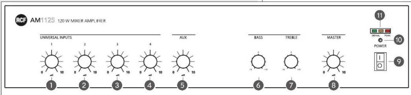
1 MIC / LINE input 1 volume control.
2 MIC / LINE input 2 volume control.
3 MIC / LINE input 3 volume control.
4 MIC / LINE input 4 volume control (AM 1125 only).
5 AUX input volume control.
TURN FULLY COUNTERCLOCKWISE (TO 0) THE CONTROLS OF THE INPUTS THAT ARE NOT USED.
6 BASS tone control.
7 TREBLE tone control.
8 MASTER volume control.
9 Main POWER switch (0 = off; I = on).
10 'POWER ON' LED (when lit: the amplifier is operating).
11 LEDs indicating the mixed audio signal level:
green = -20 dB; orange: -9 dB; red: 0 dB (peak).
0 dB = SIGNAL LEVEL THAT ALLOWS TO GET THE AMPLIFIER MAXIMUM OUTPUT POWER.
IT IS ADVISABLE TO REDUCE THE MASTER VOLUME 8 (OR A SINGLE INPUT VOLUME OF A TOO HIGH SIGNAL) WHEN THE RED LED 11 IS STEADY LIT.


AM 1125
AM 1064
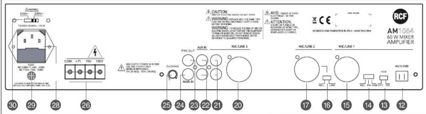
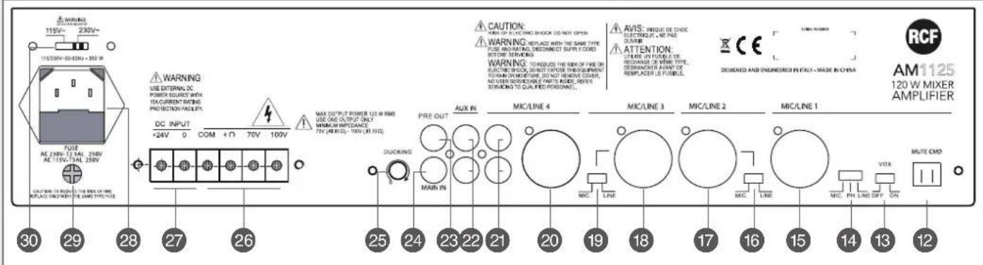
12 MUTE CMD Mute command: if the 2 contacts are short, the audio input 1 gets priority over the other inputs.
13 Audio input 1 VOX function ON / OFF switch.
The 'VOX' function automatically gives priority to the audio input 1 whenever a signal is detected at its input.
WHEN THE AUDIO INPUT 1 PRIORITY IS IN PROGRESS, ALL THE OTHER AUDIO INPUTS ARE MUTED (BUT THE AUX IN, FOR WHICH IT IS POSSIBLE TO ADJUST ITS LEVEL BY TURNING THE DUCKING CONTROL 25).
14 MIC./PH./LINE Audio input 1 MIC/LINE and 'Phantom' switch.
| MIC. | Audio input sensitivity set to MIC. The ‘Phantom’ power supply is disabled.Use: dynamic microphones. |
| PH. | Audio input sensitivity set to MIC. The ‘Phantom’ power supply is enabled.Use: electret microphones. |
| LINE | Audio input sensitivity set to LINE. The ‘Phantom’ power supply is disabled.Use: ‘line’ level signal. |
15 Audio input 1 (XLR connector):

Balanced connection + hot - cold
GND ground
Unbalanced connection
Do NOT USE AN UNBALANCED CONNECTION WHEN THE 'PHANTOM' POWER SUPPLY IS SWITCHED ON!
THE BALANCED CONNECTION IS ALWAYS PREFERABLE, ESPECIALLY WITH CABLES LONGER THAN 5 METERS.
16 MIC./LINE Audio input 2 MIC/LINE switch.
MIC. Audio input sensitivity set to MIC. Use: dynamic microphones.
LINE | Audio input sensitivity set to LINE. Use: 'line' level signal.
17 Audio input 2 (XLR connector, see 'Audio input 1' 15 for the connection).
18 (AM 1125 only) Audio input 3 (XLR connector, see 'Audio input 1' 15 for the connection).
19 (AM 1125 only) MIC./LINE Audio input 3 MIC/LINE switch.
MIC. Audio input sensitivity set to MIC. Use: dynamic microphones.
LINE Audio input sensitivity set to LINE. Use: 'line' level signal.
20 Audio input 4 (AM 1125) / 3 (AM 1064) for dynamic microphones (XLR connector, see 'Audio input 1' 15 for the connection).
21 Audio input 4 (AM 1125) / 3 (AM 1064) with dual RCA connector for 'line' level signals (i.e. CD / MP3 players, tuners, etc.).
THE TWO CHANNELS OF THE STEREO SOURCE CONNECTED TO THE AUDIO INPUT 4 (AM 1125) / 3 (AM 1064) ARE SUMMED (INSIDE THE AMPLIFIER) TO GET A MONO SIGNAL.
ALTHOUGH THE AUDIO INPUT 4 (AM 1125) / 3 (AM 1064) HAS 2 DIFFERENT CONNECTORS (XLR / RCA), THESE CANNOT BE USED TO MIX DIFFERENT SIGNALS; ONLY ONE AUDIO SOURCE CAN BE CONNECTED.
22 AUX INPUT with dual RCA connector for 'line' level signals (i.e. CD / MP3 players, tuners, etc.).
THE TWO CHANNELS OF THE STEREO SOURCE CONNECTED TO THE AUX IN ARE SUMMED (INSIDE THE AMPLIFIER) TO GET A MONO SIGNAL.



23 PRE OUT audio output (with RCA connector) that sends the same signal routed to the internal amplifier.
USE PRE OUT TO CONNECT EITHER ADDITIONAL EXTERNAL AMPLIFIERS OR AN AUDIO RECORDER.
24 MAIN IN audio input (with RCA connector) to connect an external device directly to the internal power amplifier.
IMPORTANT: BEFORE USING THIS INPUT, IT IS NECESSARY TO SET THE INTERNAL JP1 JUMPER FROM 'INT' (INTERNAL PREAMPLIFIER) TO 'EXT'.
THIS CHANGE CAN ONLY BE MADE BY AN RCF AUTHORIZED SERVICE CENTRE OR QUALIFIED PERSONNEL.
25 DUCKING Control to adjust the AUX IN level when the audio input 1 priority is in progress.
26 Amplifier output to loudspeakers, available as:
- 100 / 70 V constant voltage line
- Low impedance (min. 4 Ω).
Use 1 output only (see the manual section 'Loudspeaker connection').
Max. output power is 120 W (AM 1125) / 60 W (AM 1064).
27 (AM 1125 only) Input for the secondary 24 V dc power supply (batteries), necessary to ensure the amplifier operation even if the mains supply is unavailable.
Make sure the connection polarity + / - is correct and use a cable having wires with a suitable section (at least: 2.5 mm ^4 ).
WARNING: USE EXTERNAL DC POWER SOURCE WITH 15A CURRENT RATING PROTECTION FACILITY.
28 Mains connector with fuse.
Before connecting the power cord, verify the mains voltage (either 230 V or 115 V \~) corresponds to the amplifier operating voltage set by the respective selector 30.
FUSE
| VOLTAGE: 230 V | VOLTAGE: 115 V | |
| AM 1125 | T2.5AL 250V | T5AL 250V |
| AM 1064 | T1.6AL 250V | T3AL 250V |
29 Additional earth screw terminal.
THE METALLIC PARTS OF THE UNIT ARE EARTHED BY MEANS OF THE POWER CORD.
AN APPARATUS WITH CLASS I CONSTRUCTION SHALL BE CONNECTED TO A MAINS SOCKET OUTLET WITH A PROTECTIVE EARTHING CONNECTION.
30 Operating ac voltage selector (either 230 V or 115 V).
WARNING: A WRONG SETTING CAN DAMAGE THE AMPLIFIER!


Use 1 output only (among the 3 available: 100 V, 70 V, 4 Ω).
100 / 70 V CONSTANT VOLTAGE OUTPUTS
- Each loudspeaker shall have a line transformer with the input voltage equal to the line voltage (100 / 70 V).
- The loudspeaker total power shall not be higher than the amplifier maximum power.
COM 4Ω 70V 100V COM 4Ω 70V 100V


LOW IMPEDANCE OUTPUT (4 Ω)
- The loudspeaker total impedance shall not be lower than 4 Ω.
NOTE: A TOTAL IMPEDANCE EQUAL TO 4 Ω ALLOWS THE AMPLIFIER MAXIMUM POWER DELIVERY. A HIGHER IMPEDANCE LEADS TO A REDUCTION OF THE POWER DELIVERED BY THE AMPLIFIER (E.G. 8 Ω: APPROX. 1/2 POWER, 16 Ω: APPROX. 1/4 POWER). AN IMPEDANCE LOWER THAN 4 Ω OVERLOADS THE AMPLIFIER. - Loudspeaker models shall be chosen by considering the max. power that the amplifier can deliver.
- Loudspeaker line should be as short as possible; long cables may need large wire cross-sections.
- Do not use, at the same time, both the low impedance output (4 Ω) and the constant voltage output (100V or 70V), as this overloads the amplifier.

| AM 1064 AM 1125 | ||
| AMPLIFIER TYPE | Analogue Analogue | |
| MAX. OUTPUT POWER | 60 W 120 W | |
| FREQUENCY RESPONSE | MIC: 60 Hz ÷ 15 kHzLINE / AUX: 50 ÷ 15 kHz | MIC: 60 Hz ÷ 15 kHzLINE / AUX: 50 ÷ 15 kHz |
| DISTORTION (AT MAX. POWER) | < 1.5% < 1.5% | |
| MIC / LINE INPUT SENSITIVITY | MIC: 1.5 mV (- 54 dBu)LINE: 200 mV (- 12 dBu) | MIC: 1.5 mV (- 54 dBu)LINE: 200 mV (- 12 dBu) |
| MIC / LINE INPUT IMPEDANCE | 600 Ω (balanced) | 600 Ω (balanced) |
| AUX IN SENSITIVITY | 200 mV (- 12 dBu) 200 mV (- 12 dBu) | |
| AUX IN IMPEDANCE | 10 kΩ (unbalanced) | 10 kΩ (unbalanced) |
| MAIN IN SENSITIVITY | 1 V (+ 2 dBu) | 1 V (+ 2 dBu) |
| MAIN IN IMPEDANCE | 10 kΩ (unbalanced) | 10 kΩ (unbalanced) |
| AMPLIFIER OUTPUT TO LOUDSPEAKERS | 100 V (167 Ω) - 70 V (83 Ω)- 4 Ω | 100 V (83 Ω) - 70 V (42 Ω)- 4 Ω |
| PRE OUT LEVEL | 1 V (+ 2 dBm) | 1 V (+ 2 dBm) |
| PRE OUT IMPEDANCE | 600 Ω (unbalanced) | 600 Ω (unbalanced) |
| INPUT 1 'PHANTOM' POWER SUPPLY | > 18 V dc(max. 20 mA) | > 18 V dc(max. 20 mA) |
| LEDS | blue: power ongreen: - 20 dB signalorange: - 9 dB signalred: 0 dB signal (peak) | blue: power ongreen: - 20 dB signalorange: - 9 dB signalred: 0 dB signal (peak) |
| POWER SUPPLY | 115 V / 230 V ~ | 115 V / 230 V ~, 24 V dc |
| MAX. CONSUMPTION | 170 W | 350 W |
| OPERATING TEMPERATURE | -10 ÷ +45 °C (+14 ÷ +113 °F) | -10 ÷ +45 °C (+14 ÷ +113 °F) |
| DIMENSIONS (W, H, D) | 431 mm, 88 mm, 385 mm(19" rack - 2 units) | 431 mm, 88 mm, 385 mm(19" rack - 2 units) |
| NET WEIGHT | 10 kg | 12 kg |
USE EXAMPLE


AVVERTENZE PER LA SICUREZZA

IMPORTANTE
USCITA BASSA IMPEDENZA (4 Ω)
HEADQUARTERS:
RCF S.p.A. Italy
tel. +39 0522 274 411
e-mail: info@rcf.it
RCF UK
tel. 0844 745 1234
Int. +44 870 626 3142
e-mail: info@rcfaudio.co.uk
RCF France
tel. +33 1 49 01 02 31
e-mail: france@rcf.it
RCF Germany
tel. +49 2203 925370
e-mail: germany@rcf.it
RCF Spain
tel. +34 91 817 42 66
e-mail: info@rcfaudio.es
RCF Belgium
tel. +32 (0) 3 - 3268104
e-mail: belgium@rcf.it
RCF USA Inc.
tel. +1 (603) 926-4604
e-mail: info@rcf-usa.com




- OWNER MANUAL MANUALE D'USO
- AM 1064 AM 1125
- INDEX INDICE
- ENGLISH
- ITALIANO
- SAFETY PRECAUTIONS
- PRIMARY POWER SUPPLY FROM MAINS
- SECONDARY (/ EMERGENCY) POWER SUPPLY THROUGH BATTERIES (AM 1125 only)
- IMPORTANT
- WARNING
- NOTES ABOUT AUDIO SIGNAL CABLES
- DESCRIPTION
- INSTALLATION INTO 19" RACK CABINETS
- FRONT PANEL
- / 70 V CONSTANT VOLTAGE OUTPUTS
- LOW IMPEDANCE OUTPUT (4 Ω)
- USE EXAMPLE
- AVVERTENZE PER LA SICUREZZA
- IMPORTANTE
- USCITA BASSA IMPEDENZA (4 Ω)
- HEADQUARTERS:
Brand : RCF
Model : AM 1064
Category : Mixer