Modero MST-701 - Regulator AMX - Free user manual and instructions
Find the device manual for free Modero MST-701 AMX in PDF.


| Product Type | Touch Panel Controller |
| Brand | AMX |
| Model | Modero MST-701 |
| Display Size | 7.0 inches (diagonal) |
| Display Technology | SmoothTouch (hybrid resistive/capacitive) |
| Resolution (estimated) | 800 x 480 pixels |
| Touch | Multi-touch with gesture support |
| Processor | AMX embedded processor |
| Memory | 364 MB (approx. 317 MB free) |
| File System Storage | MicroSD: 2752 MB (approx. 2367 MB free) |
| Connectivity | Ethernet (10/100), USB 2.0, Bluetooth (via MXA-BT), Smart Card (CAC) reader |
| Audio | Internal speaker and microphone, intercom, streaming audio |
| Video Streaming | H.264, MPEG-2, Motion JPEG (up to 30 fps) |
| Power | Power over Ethernet (PoE) or external 12V DC adapter |
| Mounting | Wall-mount (back box required, sold separately) |
| Operating System | AMX Modero S Series firmware (TPDesign4 compatible) |
| Security Modes | Standard, Secure, DoD (password protection, SSH/Telnet) |
| Dimensions (approx.) | 200 x 120 x 30 mm (7.9 x 4.7 x 1.2 in) |
| Weight (approx.) | 0.5 kg (1.1 lbs) |
| Warranty | 3 years (LCD and touch overlay: 1 year) |
| Maintenance | Clean with soft, dry cloth; avoid liquids and solvents |
| Repairability | Contact AMX support; no user-serviceable parts |
Frequently Asked Questions - Modero MST-701 AMX
User questions about Modero MST-701 AMX
0 question about this device. Answer the ones you know or ask your own.
Ask a new question about this device
Download the instructions for your Regulator in PDF format for free! Find your manual Modero MST-701 - AMX and take your electronic device back in hand. On this page are published all the documents necessary for the use of your device. Modero MST-701 by AMX.
USER MANUAL Modero MST-701 AMX
Operation/Reference Guide
Modero S Series®
Programming Guide
AMX Limited Warranty and Disclaimer
This Limited Warranty and Disclaimer extends only to products purchased directly from AMX or an AMX Authorized Partner which include AMX Dealers, Distributors, VIP's or other AMX authorized entity.
AMX warrants its products to be free of defects in material and workmanship under normal use for three (3) years from the date of purchase, with the following exceptions:
- Electroluminescent and LCD Control Panels are warranted for three (3) years, except for the display and touch overlay components are warranted for a period of one (1) year.
• Disk drive mechanisms, pan/tilt heads, power supplies, and MX Series products are warranted for a period of one (1) year. - AMX lighting products are guaranteed to switch on and off any load that is properly connected to our lighting products, as long as the AMX lighting products are under warranty. AMX also guarantees the control of dimmable loads that are properly connected to our lighting products. The dimming performance or quality there of is not guaranteed, impart due to the random combinations of dimmers, lamps and ballasts or transformers.
- AMX software is warranted for a period of ninety (90) days.
- Batteries and incandescent lamps are not covered under the warranty.
- AMX AutoPatch Epica, Modula, Modula Series4, Modula CatPro Series and 8Y-3000 product models will be free of defects in materials and manufacture at the time of sale and will remain in good working order for a period of three (3) years following the date of the original sales invoice from AMX. The three-year warranty period will be extended to the life of the product (Limited Lifetime Warranty) if the warranty card is filled out by the dealer and/or end user and returned to AMX so that AMX receives it within thirty (30) days of the installation of equipment but no later than six (6) months from original AMX sales invoice date. The life of the product extends until five (5) years after AMX ceases manufacturing the product model. The Limited Lifetime Warranty applies to products in their original installation only. If a product is moved to a different installation, the Limited Lifetime Warranty will no longer apply, and the product warranty will instead be the three (3) year Limited Warranty.
All products returned to AMX require a Return Material Authorization (RMA) number. The RMA number is obtained from the AMX RMA Department. The RMA number must be clearly marked on the outside of each box. The RMA is valid for a 30-day period. After the 30-day period the RMA will be cancelled. Any shipments received not consistent with the RMA, or after the RMA is cancelled, will be refused. AMX is not responsible for products returned without a valid RMA number.
AMX is not liable for any damages caused by its products or for the failure of its products to perform. This includes any lost profits, lost savings, incidental damages, or consequential damages. AMX is not liable for any claim made by a third party or by an AMX Authorized Partner for a third party.
This Limited Warranty does not apply to (a) any AMX product that has been modified, altered or repaired by an unauthorized agent or improperly transported, stored, installed, used, or maintained; (b) damage caused by acts of nature, including flood, erosion, or earthquake; (c) damage caused by a sustained low or high voltage situation or by a low or high voltage disturbance, including brownouts, sags, spikes, or power outages; or (d) damage caused by war, vandalism, theft, depletion, or obsolescence.
This limitation of liability applies whether damages are sought, or a claim is made, under this warranty or as a tort claim (including negligence and strict product liability), a contract claim, or any other claim. This limitation of liability cannot be waived or amended by any person. This limitation of liability will be effective even if AMX or an authorized representative of AMX has been advised of the possibility of any such damages. This limitation of liability, however, will not apply to claims for personal injury.
Some states do not allow a limitation of how long an implied warranty last. Some states do not allow the limitation or exclusion of incidental or consequential damages for consumer products. In such states, the limitation or exclusion of the Limited Warranty may not apply. This Limited Warranty gives the owner specific legal rights. The owner may also have other rights that vary from state to state. The owner is advised to consult applicable state laws for full determination of rights.
EXCEPT AS EXPRESSLY SET FORTH IN THIS WARRANTY, AMX MAKES NO OTHER WARRANTIES, EXPRESSED OR IMPLIED, INCLUDING ANY IMPLIED WARRANTIES OF MERCHANTABILITY OR FITNESS FOR A PARTICULAR PURPOSE. AMX EXPRESSLY DISCLAIMS ALL WARRANTIES NOT STATED IN THIS LIMITED WARRANTY. ANY IMPLIED WARRANTIES THAT MAY BE IMPOSED BY LAW ARE LIMITED TO THE TERMS OF THIS LIMITED WARRANTY. EXCEPT AS OTHERWISE LIMITED BY APPLICABLE LAW, AMX RESERVES THE RIGHT TO MODIFY OR DISCONTINUE DESIGNS, SPECIFICATIONS, WARRANTIES, PRICES, AND POLICIES WITHOUT NOTICE.
Table of Contents
Modero S Series® Programming 1
Overview 1
Settings Pages 3
Overview 3
Accessing the Settings Page 3
Using the Settings Pages 4
Saving Changed Settings 4
Settings.... 5
Status....6
File Information 7
Display 8
Calibration....9
Sounds.... 10
Creating a Custom Sound Set 11
Audio Devices.... 11
Date & Time.... 12
Connection & Networks.... 13
Master Connection 14
Scanning for Masters.... 15
Changing the Master Connection Mode.... 15
Changing the Master IP/URL 15
Changing the Master Port Number 16
Changing the Master Username and Password 16
Network Connection 17
Setting Static IP Information 18
Entering a New Hostname 18
Bluetooth 19
Bluetooth Device Search 19
Searching For New Bluetooth Devices 20
Smart Card 22
Breakout Box.... 23
Configuration.... 24
Panel Configuration.... 25
Changing the Device Number 26
Changing the Device Name.... 26
Power Management 27
G4 WebControl 28
Function Show Example 29
Synchronizing Device Names.... 29
Admin Configuration 30
Admin Passwords 31
Security 32
Install Firmware 33
Resetting to Factory-Installed Firmware.... 33
Installing Previous Firmware.... 35
Installing New Firmware From An External USB Stick.... 35
SIP 37
Changing the SIP Proxy Address 38
Changing the SIP Port Number 38
Changing the SIP STUN Address 38
Advanced Config.... 39
Cache Settings 40
Diagnostics.... 41
Logs.... 41
Network Statistics 42
ICSP Statistics 42
Connection Utility.... 43
Streaming Video.... 43
Entering a Streaming Video URL 44
Programming 45
Overview 45
Page Commands 45
@APG 45
@CPG 45
@DPG 45
@PDR 46
@PHE.... 46
@PHP 46
@PHT 46
@PPA 47
@PPF 47
@PPG 47
@PPK 47
@PPM 48
@PPN 48
@PPT 48
@PPX 48
@PSE 49
@PSP 49
@PST 49
PAGE 49
PPOF 50
PPOG 50
PPON 50
Programming Numbers.... 51
RGB Triplets and Names For Basic 88 Colors 51
Font Styles And ID Numbers 53
Border Styles And Programming Numbers 53
“^” Button Commands 56
^ANI....56
^APF 56
^BAT 56
^BAU 57
^BCB 57
^BCF 57
^BCT 58
^BDO 58
^BFB 58
^BIM 59
^BLN 59
^BMC 60
^BMF 61
^BMI 63
^BML....63
^BMP 63
^BNC 63
^BNN 63
^BNT 64
^BOP....64
^BOR.... 64
^BOS....64
^BPP 65
^BRD 65
^BSF.... 65
^BSM 65
^BSO 65
^BSP 66
^BVL 66
^BVN....66
^BVP 66
^BVT 66
^BWW 67
^CPF 67
^DPF 67
^DVS 67
^ENA 67
^GDI....68
^GIV 68
^GLH....68
^FON 68
^GLL....69
^GRD 69
^GRU 69
^GSC....69
^GSN 69
^ICO....70
^IRM 70
^JSB 70
^JSI 71
^JST 71
^MBT 71
^MDC....71
^PIC 72
^STF 72
^SHO 72
^SKT 72
^TEC 72
^TEF 73
^TOP 73
^TXT 73
^UNI....73
Text Effects Names....74
Button Query Commands 75
?BCB 76
?BCF 76
?BCT 77
?BMP 77
?BOP 78
?BRD 78
?BWW 79
?FON....79
?ICO 80
?JSB 80
?JSI 81
?JST....81
?TEC 82
?TEF 82
?TXT 83
Panel Runtime Operations 84
ABEEP 84
ADBEEP 84
@AKB 84
AKEYB 84
AKEYP 84
AKEYR 84
@AKP 85
@AKR 85
BEEP 85
BRIT 85
@BRT 85
DBEEP 85
@EKP 86
PKEYP 86
@PKP 86
SETUP 86
SHUTDOWN 86
SLEEP 86
@SOU 87
@TKP 87
TPAGEON 87
TPAGEOFF 87
@VKB 87
WAKE 87
Panel Setup Commands 88
@PWD 88
^PWD 88
Input Commands.... 88
^KPS 88
^VKS 88
Embedded codes 89
Dynamic Image Commands.... 90
^BBR 90
^RAF 90
^RFR 91
^RFRP 91
^RMF 92
^RSR 92
^RAF, ^RMF - Embedded Codes 93
Escape Sequences 94
\$DV 94
\$SY 94
\$IP 94
\$HN 94
\$MC 94
\$ID 94
\$PX 94
\$PY 94
\$ST 94
\$AC 94
\$AP 94
\$CC 94
\$CP 94
\$LC 94
\$LP 94
\$BX 94
\$BY 94
\$BN 94
Intercom Commands 95
^MODEL? 95
^ICS- 95
^ICE' 95
^ICM-LISTEN 96
^ICM-MICLEVEL 96
^ICM-MUTEMIC 96
^PHN-MSGWAITING....98
^PHN-PRIVACY 98
^PHN-REDIAL 98
^PHN-TRANSFERRED 98
?PHN-AUTOANSWER.... 99
^PHN-CALL 99
^PHN-DTMF 99
^PHN-HANGUP 99
^PHN-HOLD 99
?PHN-LINESTATE 99
^PHN-PRIVACY 99
?PHN-PRIVACY.... 99
^PHN-REDIAL 99
^PHN-SETUP-DOMAIN 100
^PHN-SETUP-ENABLE.... 100
^PHN-SETUP-PASSWORD.... 100
^PHN-SETUP-PORT 100
^PHN-SETUP-PROXYADDR.... 100
^PHN-SETUP-STUNADDR 100
^PHN-SETUP-USERNAME 100
^PHN-TRANSFER 100
Audio Commands 101
^ADS.... 101
?ADS 101
^ICM 101
?MUT.... 101
^MUT 101
Panel-to-Panel Video Communication 102
?VOL 102
^VOL.... 102
?CAM 102
^VCE.... 102
^VCS 102
Streaming Video, MXA-MP, and MXA-MPL Commands.... 102
Subpages Commands 103
^SCE 103
^SDR.... 104
^SHD.... 104
^SSH 104
^STG 104
LED Commands.... 105
^WLD 105
Custom Events 106
Bluetooth Headsets.... 106
AMX Bluetooth Handset Custom Event 106
Dynamic Images 106
Resource Load Notification custom event.... 106
Popups 107
^PUN 107
?PUL.... 107
?PUS....107
Smart Cards.... 108
Smart Card Insert/Remove 108
Smart Card Reader Insert/Remove 108
Streaming Video.... 108
Streaming video custom event.... 108
Streaming Video 108
Custom Events for Streaming Video 108
Appendix A: Text Formatting 109
Text Formatting Codes for Bargraphs/Joysticks.... 109
Text Area Input Masking.... 110
Input mask character types 110
Input Mask Ranges 111
Input mask next field characters.... 111
Input mask operations.... 111
Input mask literals 111
Input mask output examples 112
URL Resources 112
Special Escape Sequences.... 112
Appendix B: Video Streaming Troubleshooting 115
Optimizing Motion JPEG Video Presentation and Speed 115
Transcoding Guidelines.... 116
Table of Contents
Modero S Series ^® Programming
Overview
The Modero S Series ^® line of touch panels is a cousin to the popular Modero X Series, with features optimized for specific needs. For those customers who just want a control touch panel without all of the additional features offered in the Modero X Series, the Modero S Series panels offer AMX engineering quality and industrial design, a more rugged touch interface, secure locking features, and streaming Voice Over Internet Protocol (VoIP) and video.
The Modero S Series SmoothTouch™ display offers the best blend of resistive & capacitive technologies, including single-touch gestures. A glass overlay improves display quality while extending the touch panel's lifespan and eliminates pillowing of the touch screen surface. The resultant SmoothTouch display works with fingers, gloves, or pointing devices, and resists dirt, water, and light. It also has the benefit of working in environments with high electrical noise.
This document focuses on programming information for the Modero S Series touch panels. For more information on designing touch panel pages intended to optimize the Modero S Series experience, please refer to the TPDesign4 Operation Reference Guide and the User Interface Design Guide, both available at www.amx.com.
Modero S Series ® Programming
Settings Pages
Overview
Modero S Series touch panels do not have separate Setup and Protected Setup pages. All touch panel settings and functionality are now controlled through one Settings page. The Connection & Networks and Configuration sections are accessible with the correct password.
Accessing the Settings Page
To access the Settings page, press and hold the Sleep button on the touch panel for 3 seconds. For more information on the location of the Sleep button, please refer to the Operation Reference Guide for the panel model, available at www.amx.com.
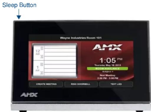
FIG. 1 Location of the Sleep button on the MST-431
Alternately, some installation circumstances may require disabling Settings page access through the Sleep button. In this case, you may access Settings pages during a bootup of the panel. As the panel boots up, watch for a series of indicator dots to appear on the splash screen (FIG. 2). To access the Settings page, press the bottom right corner of the touchscreen within the first three seconds of these dots appearing on the screen.

FIG. 2 Indicator dots on the Modero S Series splash screen

For more information on disabling Settings page access through the Sleep button, please refer to the Admin Configuration section on page 30.
Using the Settings Pages
When opened, the Settings pages appear in the center of the panel display. Please note that many of the pages may be longer than they initially appear. To reach additional functions on a given page, the page itself may be scrolled up and down, much like a smartphone display, to reveal those functions.

NOTE
The Settings pages use the subpage feature. Not all menu items on a Settings page are visible on screen at one time, and scrolling up and down to see them may be necessary. In the case of long Settings pages, a scroll bar appears momentarily when a new subpage viewer appears, and allows you to gauge current position and length of the page.
Many of the entries on Settings pages are read-only, or may be modified if information on the same or another Settings page is changed. The current information on a page appears in blue under the main category title; press the arrow to the right in order to open the category's Settings page (FIG. 3). If the arrow is grey, then the Settings page associated with that category is currently disabled (FIG. 4). This may be altered with changes in connectivity (connecting a USB stick to the touch panel, for instance) or changes to other Settings pages.
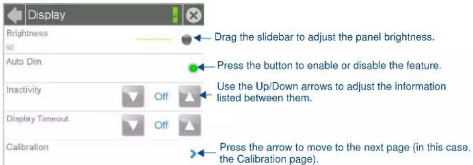
FIG. 3 Settings page with multiple modifiable sections
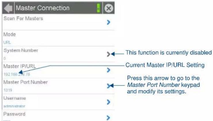
FIG. 4 Settings page with enabled and disabled arrows
Saving Changed Settings
Changes to the Settings pages are made to the device's Flash memory, and may not be saved immediately to the panel in the case of sudden power loss. To ensure that your changes are retained, always make sure to shut down the device from the main Settings page (page 5). In situations of sudden power loss, the panel may boot up at its next use with only previously saved settings, requiring resetting all of those settings to their new values.

WARNING
Modero S Series touch panels should always be shut down or rebooted by the Settings pages. Turning off a touch panel by removing power may cause damage to the touch panel's flash memory.
Settings
The Settings page (FIG. 5) controls access to all other settings pages within Modero S Series touch panels.
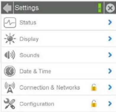
FIG. 5 Settings page
| Settings Page | |
| Back: Click the left-facing | arrow to return to the previous page. |
| Connection Status: | A green bar signifies that the panel has an active connection to the Master. |
| Close: | Click the "X" button to shut the Settings page and return to the main display. |
| Status: | Select this to go to the Status page (page 6). |
| Display: | Select this to go to the Display page (page 8) |
| Sounds: | Select this to go to the Sounds page (page 10). |
| Date & Time: | Select this to go to the Date & Time page (page 12). |
| Connection & Networks | Select this to go to the Connection & Networks page (page 13). If the lock icon is closed, you will need the correct password to access this section. |
| Configuration: | Select this to go to the Configuration page (page 24). If the lock icon is closed, you will need the correct password to access this section. |
The Connection & Networks and Configuration pages are password-protected. To open either of these pages:
- Select the appropriate page from the Settings page.
- In the Password keypad, enter the password and select OK. The default password is 1988.
Status
The Status page (FIG. 6) displays basic touch panel information, such as currently available memory and the screen resolution dimensions.
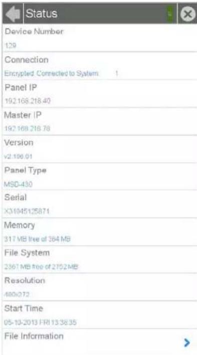
FIG. 6 Status page
| Status Page | |
| Back: Click the left-facing | arrow to return to the previous page. |
| Connection Status: | A green bar signifies that the panel has an active connection to the Master. |
| Close: | Click the "X" button to shut the Settings page and return to the main display. |
| Device Number: Displays | the panel's device number. |
| Connection: Displays the | panel's connection type. |
| Panel IP: Displays the panel's IP address. | |
| Master IP: Displays the IP | address for the panel's Master. |
| Version: Displays the current version of the panel firmware. | |
| Panel Type: Displays the panel model. | |
| Serial: Displays the specific serial number value assigned to the panel. | |
| Memory: Displays the amount of memory available on the panel. | |
| File System: | Displays the amount of MicroSD card memory available on the panel. |
| Resolution: | Displays the screen height and width in pixels. |
| Start Time: | Displays the time when the panel was last started or restarted. |
| File Information: | Select this to go to the File Information page (page 7). |
File Information
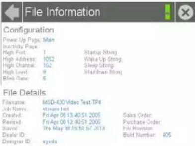
The File Information page (FIG. 7) displays information on the TPDesign4 project file currently loaded on the panel.
File Comments
FIG. 7 File Information page
| File Information Page | |
| Back: Click the left-facing arrow to return to the previous page. | |
| Connection Status: | A green bar signifies that the panel has an active connection to the Master. |
| Close: | Click the "X" button to shut the Settings page and return to the main display. |
| Configuration: This section contains information on the panel's configuration. | |
| Power Up Page: Displays the page assigned to display after the panel is powered-up. | |
| Inactivity Page: Displays the page assigned to display when the panel is in Sleep Mode. | |
| High Port: Displays the high port (port count) value for the panel. | |
| High Access: Displays the high access (access count) value for the panel. | |
| High Channel: Displays the high channel (channel count) value for the panel. | |
| High Level: Displays the high level (level count) value being used by the panel. | |
| Blink Rate: Displays the feedback blink rate, in 5-second increments. | |
| Startup String: Displays the start-up string. | |
| Wake Up String: Displays the wake up string used after an activation from a timeout. | |
| Sleep String: | Displays the sleep string used during a panel's Sleep mode. |
| Shutdown String: | Displays the shutdown string used during a panel's Shutdown mode. |
| File: | This section contains information on the particular TPDesign4 file used by the panel. |
| Filename: | Displays the name of the TPDesign4 file currently being used for the panel. |
| Job Name: Displays the job name. | |
| Created: | The creation date of the project. |
| Revised: | Displays the last revision date for the project. |
| Saved: | Displays the last save date on the project. |
| Dealer ID: | Displays the dealer ID number (unique to every dealer and entered in TPDesign). |
| Designer ID: | Displays the designer information. |
| Sales Order: | Displays the sales order information. |
| Purchase Order: | Displays the purchase order information. |
| File Revision: | Displays the revision number of the TPDesign4 file, if applicable. |
| Build Number: Displays the build number information of the TPDesign software used to create the project file. | |
| File Comments: | Displays any comments associated to the job (from the TPDesign project file). |
Display
The Display page (FIG. 8) controls the basic functions of the touch panel display, including the panel brightness.
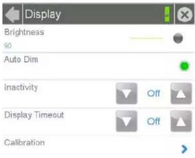
FIG. 8 Display page
| Display Page | |
| Back: Click the left-facing arrow to return to the previous page. | |
| Connection Status: | A green bar signifies that the panel has an active connection to the Master. |
| Close: | Click the "X" button to shut the Settings page and return to the main display. |
| Brightness: Sets the display brightness and contrast levels of the panel.Move the slidebar to the left or right to adjust the brightness level. | |
| Auto Dim: | Press this button to enable automatic dimming of the panel display if the Display Timeout setting is enabled. |
| Inactivity: | Indicates the length of time that the panel can remain idle before automatically flipping to a pre-selected page.Press the Up/Down buttons to increase/decrease the Inactivity Page Flip Timeout setting. Range = 1, 2, 5, 10, 15, 30 minutes, 1, 2, 3, 4 hours.Set the timeout value to Off to disable Inactivity Page mode.Note:The touch panel page used for the Inactivity page flip is named within a small Inactivity Page field below the buttons. The default reading is "MAIN". |
| Display Timeout: | Indicates the length of time that the panel can remain idle before the display automatically powers down.Press the Up/Down buttons to increase/decrease the Display Timeout setting. Range = 1, 2, 5, 10, 15, 30 minutes, 1, 2, 3, 4 hours.Set the timeout value to Off to disable Display Timeout mode. |
| Calibration: | Select this to open the Calibration page (page 9). |
Calibration
In certain circumstances, it may be necessary to calibrate the touch panel's touch screen, in order to guarantee accurate button selection. The Calibration page (FIG. 9) offers two options: the opportunity to calibrate the touch panel, and the opportunity to ensure that a previous calibration is still accurate.
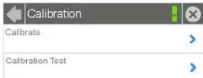
FIG. 9 Calibration page
To calibrate the touch panel:
- From the Settings page, select Display.
-
From the Display page, select Calibration.
-
To calibrate the touch panel, select Calibrate to open the Calibration page (FIG. 10).
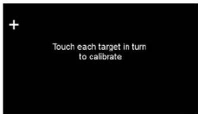
FIG. 10 Panel calibration
- Follow the instructions, touching the crosshairs in order across the screen.
- The page will read "Calibration Successful. Touch to continue." Touch anywhere on the screen to return to the Calibration page.

If the screen is not touched at that point, the device will automatically return to the Calibration page within 10 seconds.
In certain circumstances, you may wish to test the calibration of a panel without actually recalibrating it. The Calibration Test page (FIG. 11) may be used to verify the accuracy of that calibration.
To calibrate the touch panel:
- From the Settings page, select Display.
- From the Display page, select Calibration.
- To test the calibration of the touch panel, select Calibration Test to open the Calibration Test page (FIG. 11).
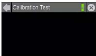
FIG. 11 Calibration Test page
- Touch the screen and note the positioning of the crosshairs based on where you touch.
- If the crosshairs do not match the places where you touch, then go back to calibrate the panel.
Sounds
The Sounds page (FIG. 12) allows adjustment of volume levels and panel sounds settings.
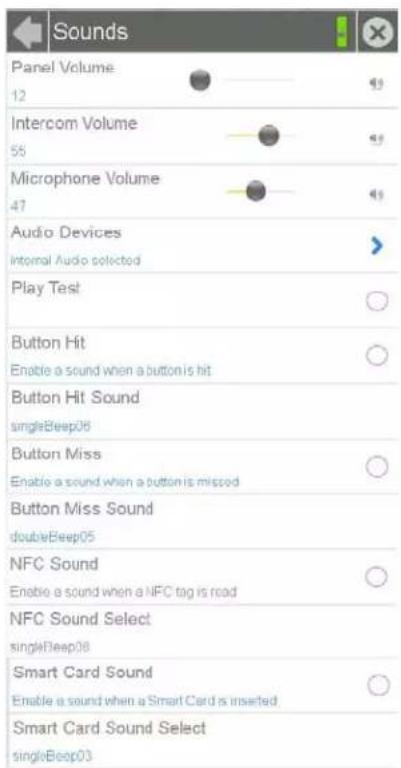
FIG. 12 Sounds page
| Sounds Page | |
| Back: Click the left-facing arrow to return to the previous page. | |
| Connection Status: | A green bar signifies that the panel has an active connection to the Master. |
| Close: | Click the “X” button to shut the Settings page and return to the main display. |
| Panel Volume: • Move the | slider to the left or right to adjust the panel volume.• Press the Mute icon to mute the panel. |
| Intercom Volume: | • Move the slider to the left or right to adjust the intercom volume.• Press the Mute icon to mute the intercom. |
| Microphone Volume: | • Move the slider to the left or right to adjust the microphone input volume.• Press the Mute icon to mute the microphone input. |
| Audio Devices: | Click this to open the Audio Devices page (page 11). |
| Play Test: | Press this button to test the audio output by playing a preselected sound. |
| Button Hit: | Press this button to enable the panel to play a default sound whenever a button on a page is selected. |
| Button Hit Sound: | Displays the information on the sound file associated with the Button Hit function. Press repeatedly to scroll through the 10 included sounds. |
| Button Miss: | Press this button to enable the panel to play a default sound when you touch a non-active button or any area outside of the active button. |
| Button Miss Sound: | Displays the information on the sound file associated with the Button Miss function. Press repeatedly to scroll through the 10 included sounds. |
| NFC Sound: | This button is disabled. |
| NFC Sound Select: | This button is disabled. |
| Sounds Page (Cont.) | |
| Smart Card Sound: | Press this button to enable the panel to play a default sound when the panel detects a CAC card. (For more information on CAC card functionality, please refer to the Smart Card section on page 22.) |
| Smart Card Sound Select: | Displays the information on the sound file associated with the Smart Card Sound function. Press repeatedly to scroll through the 10 included sounds. |
Creating a Custom Sound Set
Instead of using the 10 sounds included as default selections on each setting, the Button Hit Sound, Button Miss Sound, NFC Sound and Smart Card Sound may also have a 'custom' sound set by the user. To do this, create a resource in TPDesign 4 for each custom sound, named "customSingle.wav," "customDouble.wav," "customNfc.wav," and "customSmartCard.wav," respectively.
Audio Devices
The Audio Devices page (FIG. 13) allows control of audio input and output both from the touch panel's internal microphone (in a Modero S Series touch panel with microphone functionality) and speaker, or from external USB or Bluetooth devices.
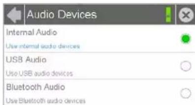
FIG. 13 Audio Devices page
| Audio Devices Page | |
| Back: Click the left-facing arrow to return to the previous page. | |
| Connection Status: | A green bar signifies that the panel has an active connection to the Master. |
| Close: | Click the “X” button to shut the Settings page and return to the main display. |
| Internal Audio: | Click this button to allow audio input from the touch panel’s microphone, if available. |
| USB Audio: | Click this button to allow audio input and output from and to devices connected to the touch panel. If no devices are connected via USB, this button will be greyed out. |
| Bluetooth Audio: | Click this button to allow audio input and output from and to devices connected to the touch panel via Bluetooth. If no devices are connected via Bluetooth, or if the touch panel does not offer Bluetooth support, this button will be greyed out. (For more information on Bluetooth connectivity, please refer to the Bluetooth section on page 19.) |
Date & Time
The Date & Time page (FIG. 14) allows setting and adjusting of time and date information on the Modero S Series touch panel. If the time and/or date on the Master is modified, all connected devices will be updated to reflect the new information.
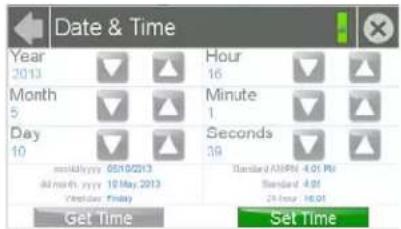
FIG. 14 Date & Time page
| Date & Time Page | |
| Back: Click the left-facing arrow to return to the previous page. | |
| Connection Status: | A green bar signifies that the panel has an active connection to the Master. |
| Close: | Click the "X" button to shut the Settings page and return to the main display. |
| Year: | Use the Up/Down arrows to set the current year. |
| Month: | Use the Up/Down arrows to set the current month. |
| Day: | Use the Up/Down arrows to set the current day. |
| Hour: | Use the Up/Down arrows to set the current hour. |
| Minute: | Use the Up/Down arrows to set the current minute. |
| Seconds: | Use the Up/Down arrows to set the current second. |
| Current Date: Displays the currently set date on the touch panel. | |
| Current Time: | Displays the currently set time on the touch panel. |
| Get Time: | The Get Time button retrieves time/date information from the Master. |
| Set Time: | The Set Time button retains and saves any time/date modifications made on the panel. |
The current date and time may be retrieved from the NetLinx Master, or it may be updated manually. To retrieve the date and time from the Master:
- From the Date & Time page, press the Get Time button.
- The new time and date will be added.
- Press the Back button to save the changes.
Connection & Networks
The Connections & Networks page (FIG. 15) is the center for several networking functions, including connecting the touch panel to a Master, connecting it to a network, allowing Bluetooth functionality, and controlling video functionality.
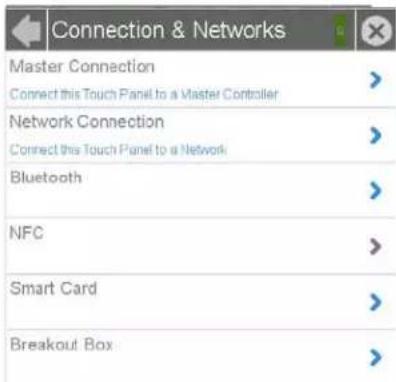
FIG. 15 Connection & Networks page
| Connection & Networks Page | |
| Back: Click the left-facing arrow to return to the previous page. | |
| Connection Status: | A green bar signifies that the panel has an active connection to the Master. |
| Close: | Click the “X” button to shut the Settings page and return to the main display. |
| Master Connection: | Opens the Master Connection page (page 14). |
| Network Connection: | Opens the Network Connection page (page 17) |
| Bluetooth: | Opens the Bluetooth page (page 19). |
| NFC: This button is disabled. | |
| Smart Card: | Opens the Smart Card page (page 22). |
| Breakout Box: | Opens the Breakout Box page (page 23). |
Master Connection
The Master Connection page (FIG. 16) controls the method of connection to a NetLinx Master.
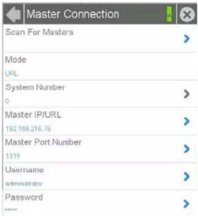
FIG. 16 Master Connection page
| Master Connection Page | |
| Back: Click the left-facing | arrow to return to the previous page. |
| Connection Status: | A green bar signifies that the panel has an active connection to the Master. |
| Close: | Click the "X" button to shut the Settings page and return to the main display. |
| Scan For Masters | Click this button to open the Master Scan page (page 15). |
| Mode: | Cycles between the connection modes: URL, Listen, and Auto.URL - In this mode, enter the IP/URL, Master Port Number, and username/password (if used) on the Master. The System Number field is read-only - the panel obtains this information from the Master.Listen - In this mode, add the panel address into the URL List in NetLinx Studio and set the connection mode to Listen. This mode allows the Modero touch panel to "listen" for the Master's communication signals. The System Number and Master IP/URL fields are read-only.Auto - In this mode, enter the System Number and a username/password (if applicable). Use this mode when both the panel and the NetLinx Master are on the same Subnet. The Master IP/URL field is read-only. |
| System Number: Allows entry of a system number. Default value is 0 (zero).NOTE: Available in Auto Mode Only - disabled when URL or Listen is selected. | |
| Master IP/URL: Sets the Master IP or URL of the NetLinx Master.NOTE: Available in URL Only - disabled when Listen or Auto is selected. | |
| Master Port Number: Allows entry of the port number used with the NetLinx Master.Default = 1319. | |
| Username: | If the target Master has been previously secured, enter the alpha-numeric string (into each field) assigned to a preconfigured user profile on the Master. This profile should have the predefined level of access/configuration rights. |
| Password: | If the target Master has been previously secured, enter the alpha-numeric string (into each field) assigned to a preconfigured user profile on the Master. This profile should have the predefined level of access/configuration rights. |
Scanning for Masters
To quickly and easily identify all of the available Masters on the network, use the Scanning for Masters page. The site survey on this page passively listens to network traffic and presents all the compatible Masters for easy selection. Selecting the desired Master automatically updates the Master connection and makes an automatic connection.
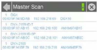
FIG. 17 Master Scan page
To scan for available Masters:
- From the Master Connection page, press the Scanning For Masters button.
- In the Master Scan page, select the Master for the Modero S Series panel. The Master Connection page will automatically display the information on the selected Master.
Changing the Master Connection Mode
To change the Master Connection mode between URL, Listen, and Auto:
- From the Master Connection page, press the Mode field to change the mode.
- Keep pressing to bring up the desired mode.
- When finished, press Back to return to the Settings page.
Changing the Master IP/URL
To change the IP address or URL for the chosen Master:
- From the Master Connection page, press the Master IP/URL field to open the Master IP Address keyboard (FIG. 18).
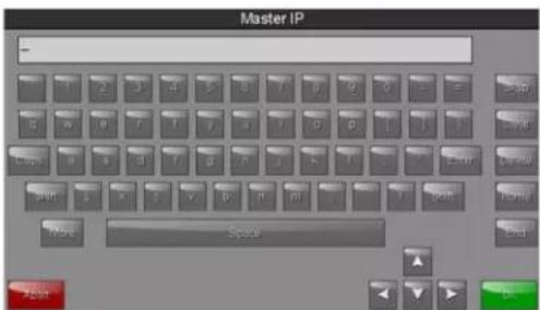
FIG. 18 Master IP Address keyboard
- Enter the IP address or the URL in the keyboard field and press OK.
- The new IP address/URL is now displayed in the Master IP/URL field.
- When finished, press Back to return to the Settings page.
Changing the Master Port Number
To change the Master Port Number from its default:
- From the Master Connection page, press the Master Port Number field to open the Master Port Number keypad (FIG. 19).
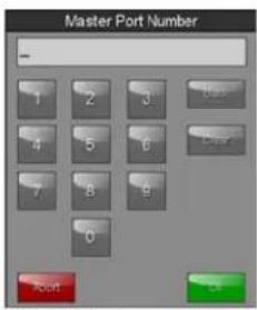
FIG. 19 Master Port Number keypad
- Enter the new Master Port Number and press OK.
- The new Master Port Number is now displayed in the Master Port Number field.
Changing the Master Username and Password
To change the current username used by the touch panel to access the Master:
- From the Master Connection page, press the Username field to open the Master User keyboard (FIG. 20).
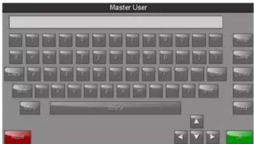
FIG. 20 Master User keyboard
- Enter the new username in the keyboard field and press OK.
- When finished, press Back to return to the Settings page.
To change the password:
- From the Master Connection page, press the Password field to open the Master Password keyboard (FIG. 21).
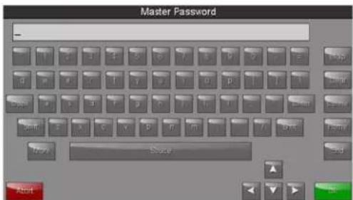
FIG. 21 Master Password keyboard
- Enter the new password in the keyboard field and press OK.
- When finished, press Back to return to the Settings page.
Network Connection
The Network Connection page (FIG. 22) controls the configuration of settings for Ethernet communication with the touch panel.
| Network Connection | |
| DHCP/Static | |
| DHCP | |
| IP Address | > |
| 192.168.218.93 | |
| Subnet Mask | > |
| 255.255.254.0 | |
| Gateway | > |
| 192.168.218.2 | |
| Hostname | > |
| localhost | |
| Domain | > |
| uninternal | |
| Primary DNS | > |
| 192.168.20.6 | |
| Secondary DNS | > |
| 192.168.20.5 | |
| MAC Address | |
| F8.07.5E.77.FF.CF | |
FIG. 22 Network Connection page
| Network Connection Page | |
| Back: Click the left-facing arrow to return to the previous page. | |
| Connection Status: | A green bar signifies that the panel has an active connection to the Master. |
| Close: | Click the "X" button to shut the Settings page and return to the main display. |
| DHCP/Static: Sets the panel to either DHCP or Static communication modes.DHCPis an IP Address assigned to the panel by a DHCP server. If DHCP is selected, the other Network Connection fields are disabled (see below).Static IPis a permanent IP Address assigned to the panel. If Static IP is selected, the other Network Connection fields are enabled. | |
| IP Address: | Displays the IP address for this panel. If DHCP is enabled, this field will be greyed out. |
| Subnet Mask: | Displays the subnetwork for this panel. If DHCP is enabled, this field will be greyed out. |
| Gateway: | Displays the gateway address for this panel. If DHCP is enabled, this field will be greyed out. |
| Hostname: Displays the hostname for this panel. | |
| Domain: | Displays a name to the panel for DNS look-up. If DHCP is enabled, this field will be greyed out. |
| Primary DNS: | Displays the address of the primary DNS server used by this panel for host name lookups. If DHCP is enabled, this field will be greyed out. |
| Secondary DNS: | Displays the secondary DNS address for this panel. If DHCP is enabled, this field will be greyed out. |
| MAC Address: | This unique address identifies the Ethernet connection in the panel (read-only). |
Setting Static IP Information
When using DHCP settings for a panel, the DHCP server will automatically populate almost all of the Network Connections page fields, with the exception of Hostname. When setting the panel for Static, however, this information must be entered manually. To enter the network connection information:
-
In DHCP/Static, press the field until the entry reads "Static". This enables all of the editable Network Connections page fields.
-
Select the IP Address field to open the Wired IP Address keypad (FIG. 23).
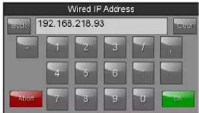
FIG. 23 Wired IP Address keypad
- Enter the server's IP address and click OK.
- Repeat this procedure with the other fields on the Network Connections page.
- When finished, the new connection information will be visible in the Network Connections page.
Entering a New Hostname
In order to facilitate DNS lookup of the panel, you should choose a new hostname for the panel.

If the "Synchronize Device Names" option in the Panel Configuration page (page 29) is enabled, the hostname is greyed out in the Network Connection page and automatically set to the Device Name.
To add a new hostname, or to change an existing one:
- From the Connection & Networks page, select Network Connection to open the Network Connection page.
- From the Network Connection page, select Hostname to open the Host Name keyboard (FIG. 24).
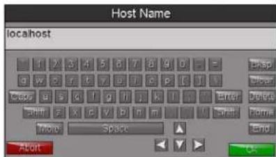
FIG. 24 Host Name keyboard
- Enter the new hostname and press OK.
- The new hostname will now appear in the Hostname field.
Bluetooth
The Bluetooth page (FIG. 25) controls whether a touch panel allows access to previously selected Bluetooth devices, as well as allowing new devices' access.
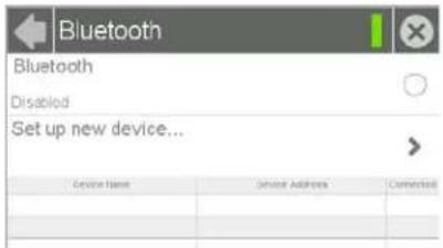
FIG. 25 Bluetooth page
| Bluetooth Page | |
| Back: Click the left-facing | arrow to return to the previous page. |
| Connection Status: | A green bar signifies that the panel has an active connection to the Master. |
| Close: | Click the "X" button to shut the Settings page and return to the main display. |
| Bluetooth: | Click this button to enable or disable Bluetooth device access to the touch panel. |
| Set up new device...: | Select to open the Bluetooth Device Search page (FIG. 26). |
| Device Name: Displays the | name of the Bluetooth paired device. |
| Device Address: Displays | the device of the Bluetooth paired device. |
| Connected: Displays if the | device is currently connected to the touch panel. |
| Disconnect: | After choosing a Bluetooth paired device, select this button to disconnect the paired device but keep it in the list. |
| Remove: | After choosing a Bluetooth paired device, select this button to remove the device from the list. |
| Up/Down: | Use the Up/Down arrows to select the Bluetooth device currently connected to the touch panel. |
Bluetooth Device Search
The Bluetooth Device Search page (FIG. 26) allows you to search for new Bluetooth devices, or ones already paired to the panel, and allow them to connect to the panel.
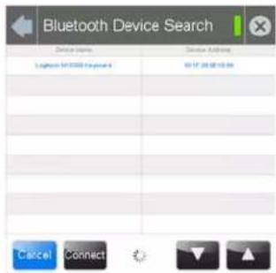
FIG. 26 Bluetooth Device Search page
| Bluetooth Device Search Page | |
| Back: Click the left-facing arrow to return to the previous page. | |
| Connection Status: | A green bar signifies that the panel has an active connection to the Master. |
| Close: | Click the “X” button to shut the Settings page and return to the main display. |
| Device Name: | This is the device name of the Bluetooth device currently on the network. |
| Device Address: | This is the device address of the Bluetooth device currently on the network. |
| Cancel: Press this button to cancel adding new devices to the page. | |
| Bluetooth Device Search Page (Cont.) | |
| Connect: | Press this button to connect a newly detected device to the network. |
| Up/Down: | Press the Up and Down buttons to select a particular Bluetooth device before connecting it. |
Searching For New Bluetooth Devices
Modero S Series touch panels have the capability of detecting active Bluetooth devices connected to their network through a MXA-BT Bluetooth USB Adaptor (FG5968-19). Once paired with the panel, a Bluetooth device may go out of range of the MXA-BT and lose a connection, but automatically reconnect once it returns within range.

The Bluetooth device must be put into Pairing Mode before enabling the panel to search for Bluetooth connections.
To search for new Bluetooth devices in the vicinity:
- Install the MXA-BT Bluetooth USB Adaptor in a USB port on the touch panel. With wall-installed touch panels, this may require temporarily removing the panel from its back box in order to reach a USB port.
- From the Bluetooth page, select Set Up New Device... to open the Bluetooth Device Search page.
- The panel automatically starts searching for unpaired and paired Bluetooth devices within its range (FIG. 27). When it finds devices within its range, these will be displayed in the Device Name and Device Address fields. The panel will continue to search for Bluetooth devices within its range for 30 seconds.
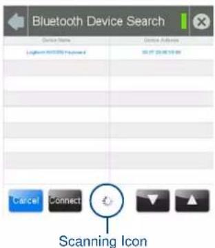
FIG. 27 Searching for Bluetooth devices
- When the panel is finished scanning for Bluetooth devices, those devices still need to be paired with the touch panel if they have not done so before. In the search list, select the device to be paired and click Connect (FIG. 28).
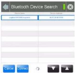
FIG. 28 Selecting a Bluetooth device
- In the Enter Pincode keypad (FIG. 29), enter the device's pincode. The default pincode is 0000.
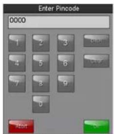
FIG. 29 Enter Pincode keypad

You must enter the pincode within 30 seconds.
- If a pincode needs to be entered from the device, a System Message popup window appears, requesting that this be done (FIG. 30).
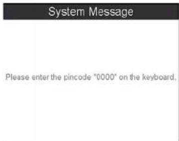
FIG. 30 System Message: Please enter the pincode
- Once the pincode has been entered, a new System Message popup window appears, noting that pairing is in progress (FIG. 31).
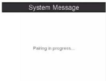
FIG. 31 System Message: Pairing in progress...
- When the pairing is finished, the new device appears on the main Bluetooth page (FIG. 32).
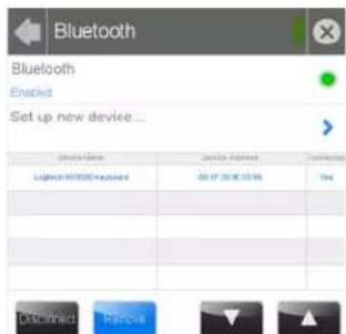
FIG. 32 Detected Bluetooth devices on the Bluetooth page
Smart Card
The Smart Card page (FIG. 33) controls the touch panel's ability to receive and process information from Common Access Card (CAC) smart card readers.

NOTE
Use of this feature requires the use of an AMX-approved CAC reader, as shown below.
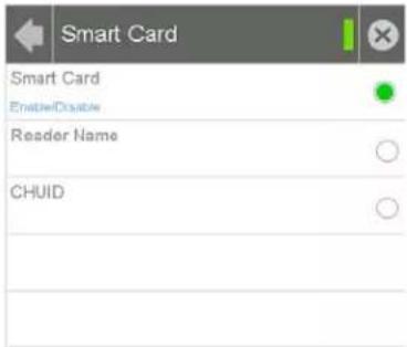
FIG. 33 Smart Card page
| Smart Card Page | |
| Back: Click the left-facing arrow to return to the previous page. | |
| Connection Status: | A green bar signifies that the panel has an active connection to the Master. |
| Close: | Click the “X” button to shut the Settings page and return to the main display. |
| Smart Card: | Click this button to enable or disable the touch panel’s ability to use smart card readers |
| Reader Name: Click this button to enable or disable displaying the smart card reader’s name and model. | |
| CHUID: | Click this button to enable or disable displaying the card’s Card Holder Unique Identifier (CHUID) number. |
At this time, three CAC readers are approved for use with the Modero S Series touch panels. Each has different methods of displaying the detection of valid smart cards, but all connect to the touch panel via the touch panel's USB port. These three models are:
• SCM Microsystems SCR3310 USB Card Reader
- SCM SCR331 USB Common Access CAC Smart Card Reader
• SCM SCR3500 Smart Card Reader
To enable a touch panel to use a CAC reader:
- From the Smart Card page, press the Smart Card button. This enables the panel to receive CAC card information.
- Following the manufacturer's instructions, connect the CAC reader to the touch panel via the touch panel's USB port.
- If desired, the touch panel may emit a sound to inform the user that a valid smart card has been detected by the reader. From the Sounds page (page 10), enable the panel to emit sounds when detecting a smart card, and choose one of the ten preloaded sounds.

NOTE
For more information on smart card programming, please refer to the Smart Cards section on page 108.
When using a CAC reader, please note that different readers have different display standards. For instance, with devices that have an LED, some light up to show that the device is connected to the touch panel, while others will only light up upon insertion of a valid smart card. The one certain way to ensure that a CAC reader is working correctly is to look for the CHUID number in the CHUID field of the Smart Card page. If a user inserts a card into a CAC reader and the CHUID number is not displayed, either the card is an invalid or damaged smart card, or the CAC reader is not connected to the touch panel or otherwise damaged.
Breakout Box
To use the MXA-MP Multi Preview or MXA-MPL Multi Preview Live devices for video stream display, the Modero S Series touch panel to which it is connected needs to be configured to receive its signals. If a Breakout Box is not connected to the panel's network, all fields but the Breakout Box button will be empty.

NOTE
For more information on operation and configuration of an MXA-MP or MXA-MPL, please refer to the MXA-MP/MPL Operation Reference Guide, available at www.amx.com.
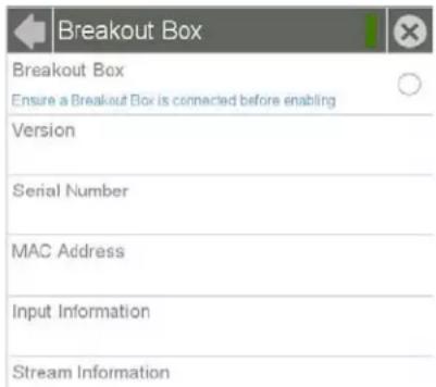
FIG. 34 Breakout Box page
| Breakout Box Page | |
| Back: Click the left-facing arrow to return to the previous page. | |
| Connection Status: | A green bar signifies that the panel has an active connection to the Master. |
| Close: | Click the “X” button to shut the Settings page and return to the main display. |
| Breakout Box: | Click this button to enable the touch panel to receive information from the device. |
| Version: Displays the current firmware version on the Breakout Box. | |
| Serial Number: Displays the serial number of the Breakout Box. | |
| MAC Address: Displays the MAC address of the Breakout Box. | |
| Input Information: | Displays the video format and resolution coming from the video input port. |
| Stream Information: This feature is currently disabled. | |
To configure the touch panel:
- From the Breakout Box page, press the Breakout Box button to enable the panel to receive information from the device.
- If the device is connected, the remaining information on the Breakout Box page will self-populate as the touch panel receives that information from the device.

NOTE
If the device is not connected to the touch panel at this time, any attempts at enabling the device will fail, and the Breakout Box page will be blank other than the Breakout Box button. If an MXA-MP or MPL is not connected to the touch panel, the Breakout Box button MUST be disabled to prevent network conflicts.
Configuration
The Configuration page (FIG. 35) allows confirmation of and changes to panel configuration information.
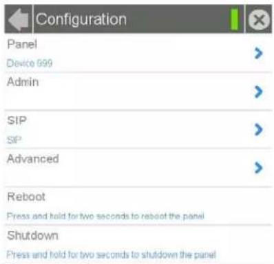
FIG. 35 Configuration page
| Configuration Page | |
| Back: Click the left-facing | arrow to return to the previous page. |
| Connection Status: | A green bar signifies that the panel has an active connection to the Master. |
| Close: | Click the "X" button to shut the Settings page and return to the main display. |
| Panel: | Select this to open the Panel Configuration page (page 25). |
| Admin: | Select this to open the Admin Configuration page (page 30). |
| SIP: | Select this to open the SIP page (page 37). |
| Advanced: | Select this to open the Advanced Config page (page 39). |
| Reboot: Press and hold this | s button for two seconds to reboot the touch panel. |
| Shutdown: | Press and hold this button for two seconds to shut down the touch panel. |
Panel Configuration
The Panel Configuration page (FIG. 36) allows configuration and updating of the touch panel's device name and device number, access to power management and G4 Web control features, and configuration of the panel's motion and light sensors.
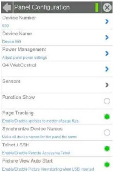
FIG. 36 Panel Configuration page
| Panel Configuration Page | |
| Back: Click the left-facing arrow to return to the previous page. | |
| Connection Status: | A green bar signifies that the panel has an active connection to the Master. |
| Close: | Click the "X" button to shut the Settings page and return to the main display. |
| Device Number: | Select this to open a keypad used to view or change the device number of the panel. |
| Device Name: | Select this to open a keyboard used to view or change the device name used for the panel. |
| Power Management: | Select this to open the Power Management page (page 27). |
| G4 WebControl: | Select this to open the G4 Web Control page (page 28). |
| Sensors: This selection is greyed out. | |
| Function Show: | When the Function Show feature is displayed, the Channel Port and Code will appear in yellow, the Address Port and Code in blue, and the Level Port and Channel Code in purple (FIG. 41). |
| Page Tracking: | Click this button to enable or disable the panel sending page flip tracking to the Master. |
| Synchronize Device Names: | Click this button to synchronize the Device Name, Hostname, and G4 Web Control Names (page 29). If this is enabled, only the Device Name can be modified, but this will be populated to the other names as well. |
| Telnet/SSH: | Click this button to enable or disable remote access to the panel via Telnet. |
| Picture View Auto Start: | Click this button to allow Picture View to start automatically once the panel detects a suitable USB stick. |
Changing the Device Number
To change the touch panel's Device Number within the network:
- From the Panel Configuration page, select the Device Number field. This opens the Device Number keypad (FIG. 37).
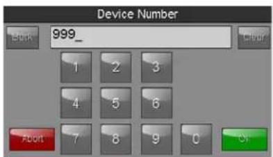
FIG. 37 Device Number keypad
- Enter the new device number and press OK.
- The Device Number field in the Panel Configuration page will now display the new device number.
Changing the Device Name
To change the name associated with the touch panel:
- From the Panel Configuration page, select the Device Name field to open the Device Name keyboard (FIG. 38).
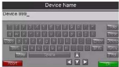
FIG. 38 Device Name keyboard
- Enter the new device name and press OK.
Power Management
The options on the Power Management page (FIG. 39) allow setting of display timeout and panel shutdown preferences.
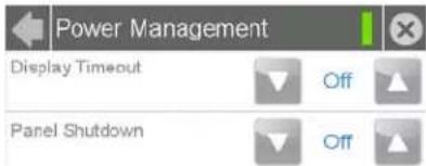
FIG. 39 Power Management page
| Power Management Page | |
| Back: Click the left-facing arrow to return to the previous page. | |
| Connection Status: | A green bar signifies that the panel has an active connection to the Master. |
| Close: | Click the "X" button to shut the Settings page and return to the main display. |
| Display Timeout: | This value determines the number of seconds, minutes, or hours that need to pass before the panel automatically goes into Sleep Mode. Once asleep, the device may be awakened by touching the Sleep button on the top of the panel or the screen itself. Use the Up/Down arrows to change the settings; a value of Off disables this feature.Range = 10, 15, 20, 25, 30 seconds; 5, 15, 30 minutes; 1, 2 hours Default = Off |
| Panel Shutdown: | This value determines the number of seconds, minutes, or hours that need to pass before the panel automatically shuts down. Use the Up/Down arrows to change the settings; a value of Off disables this feature. Once the touch panel is shut down, the Sleep button must be pressed to wake up the panel.Range = 3, 5, 10, 15. 30 minutes; 1, 2, 3, 4 hours Default = Off |
G4 WebControl
An on-board VNC (Virtual Network Computing) server allows any remote PC running a VNC client to connect to the panel. Once connected, the client can view and control the panel remotely. The options on the G4 WebControl page (FIG. 40) allow you to enable or disable G4 WebControl functionality.
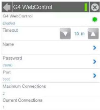
FIG. 40 G4 WebControl page
| G4 WebControl Page | |
| Back: Click the left-facing arrow to return to the previous page. | |
| Connection Status: | A green bar signifies that the panel has an active connection to the Master. |
| Close: | Click the "X" button to shut the Settings page and return to the main display. |
| G4 WebControl: | The G4 Web Control button toggles between the two G4 activation settings:Off - deactivates G4 Web Control on the panel.On - activates G4 Web Control on the panel. |
| Timeout: | Sets the length of time (in minutes) that the panel can remain idle, detecting no cursor movements, before the G4 Web Control session is terminated.Minimum value = Off (panel never times out)Maximum value = 4 h (panel times out after 4 hours) |
| Name: | Use this field to enter a unique alpha-numeric string to be used as the panel's display name. If the Synchronize Device Names option (page 29) is enabled, this field will be greyed out. |
| Password: | Use this field to enter the G4 Authentication session password required for VNC access to the panel. |
| Port: Use this field to enter the number of the port used by the VNC Web Server.Default = 5900. | |
| Maximum Connections: | Displays the maximum number of users that can be simultaneously connected to this panel via VNC. Press this field to increase the number allowed to connect to this panel. Default = 1. |
| Current Connections: | Displays the number of users currently connected to this panel via VNC. |

The Modero S Series touch panels accelerate graphics rendering through hardware, not software. When accessing the panel via VNC, a separate software graphics engine is used, which may slow down graphics and panel responsiveness. In addition to slowing down graphics and panel responsiveness, any video and animated transitions will not be visible over VNC.
Function Show Example

NOTE
When the Function Show feature is displayed, the Channel Port and Code will appear in yellow, the Address Port and Code in blue, and the Level Port and Code in purple.
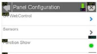
FIG. 41 Function Show
Synchronizing Device Names
For ease of connectivity, it may be desirable or necessary to make sure that all of the names registered with the panel are the same. Enabling the Synchronize Device Names button synchronizes these names, tracking any changes to the current Device Name setting. If this button is disabled, Hostname and G4 Web Control names may be changed individually.

NOTE
The Synchronize Device Names button is disabled by default.
To synchronize all device names used by a panel:
- From the Panel Configuration page, select the Synchronize Device Names button.
- A System Message popup window appears, giving the option to synchronize multiple names to the Device Name (FIG. 42). When a five-second timer ends, the Yes button will be enabled.
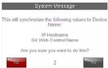
FIG. 42 System Message: This will synchronize the following values to Device Name
- Click Yes when enabled. This will automatically synchronize all names to the current Device Name.
Admin Configuration
The Admin Configuration page (FIG. 43) allows control of access to the Settings pages, passwords, security settings, and the ability to install firmware or touch panel pages from various sources.
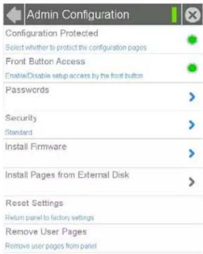
FIG. 43 Admin Configuration page
| Admin Configuration Page | |
| Back: Click the left-facing arrow to return to the previous page. | |
| Connection Status: | A green bar signifies that the panel has an active connection to the Master. |
| Close: | Click the "X" button to shut the Settings page and return to the main display. |
| Configuration Protected: | Press this button to protect the Settings pages from access without a password. |
| Front Button Access: | Press this button to enable or disable the ability to access the Settings pages from the Sleep button (FIG. 1).NOTE: If Sleep button access is disabled, the Settings page can be through the splash page, as shown in the Accessing the Settings Page section on page 3. The Settings page may also be accessed via Telnet, send command, or a preconfigured setup button on touch panel pages. |
| Passwords: | Select this to access the Passwords page (page 31). |
| Security: | Select this to open the Security page (page 32). |
| Install Firmware: | Select this to access the Install Firmware page (page 33). |
| Install Pages from External Disk: | Select this to install touch panel pages from an external disk, such as a USB stick. If an external disk is not connected to the touch panel, this field will be greyed out. |
| Reset Settings: | Select this to reset all settings and return them to the panel's factory defaults. |
| Remove User Pages: Select this to remove all currently loaded user pages from the panel. | |
Admin Passwords
The options on the Admin Passwords page allow assignment of passwords required for users to access the secured Settings pages.
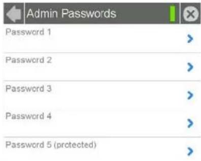
FIG. 44 Admin Passwords page
| Passwords Page | |
| Back: Click the left-facing arrow to return to the previous page. | |
| Connection Status: | A green bar signifies that the panel has an active connection to the Master. |
| Close: | Click the “X” button to shut the Settings page and return to the main display. |
| Password 1-4 | Accesses the alphanumeric password. Select PASSWORD 1, 2, 3, or 4 to open a keyboard to enter alphanumeric values associated with the selected password. |
| Password 5 (protected): | Accesses the alphanumeric values associated to particular password sets. Select PASSWORD 5 (protected) to open a keyboard to enter alphanumeric values associated with the selected password.Note: Clearing Password #5 removes the need to enter a password before accessing secured Settings pages. |
To change a previously established password:
- In the Passwords page, select the appropriate entry for the particular password to be changed. This opens a password keyboard (FIG. 45).

Password 5 is protected, and can only be changed by the Administrator.
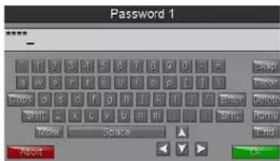
FIG. 45 Password 1 keyboard
-
In the Password keyboard, enter the new alphanumeric password.
-
Press OK when complete.
Security
The Security page (FIG. 46) allows you to select between the three security options available on the panel: Standard, Secure, and DoD.
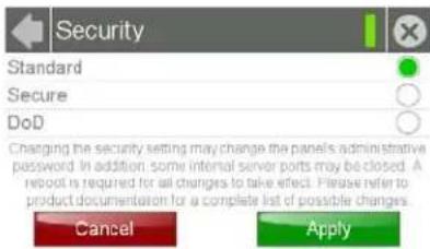
FIG. 46 Security page
| Security Page | |
| Back: Click the left-facing | arrow to return to the previous page. |
| Connection Status: | A green bar signifies that the panel has an active connection to the Master. |
| Close: | Click the "X" button to shut the Settings page and return to the main display. |
| Standard: | Click this button to set security to Standard (see below). |
| Secure: | Click this button to set security to Secure (see below). |
| DoD: | Click this button to set security to DoD (see below). |
| Cancel: | Click this button to return to the Admin Configuration page without saving any changes made to this page. |
| Apply: | Click this button to save any changes made to this page and return to the Admin Configuration page. |
Each of the settings on this page has different features for touch panel security:
| Security Profile Features | |
| Standard:• Factory default, shipped in this configuration. | Default Password is 1988.Remote login uses Telnet. |
| Secure: | Default Protected Setup Password is Amx1234!.Minimum password requirement is 8 characters with at least one numeric character.Remote login uses SSH.Remote login user name is amx.Login failure attempt pauses 4 seconds before another login attempt is allowed.After 3 consecutive unsuccessful SSH login attempts, login lockout is enabled for 15 minutes.Login and logout audit logging is enabled. |
| DoD: | Default Protected Setup Password is Amx1234!.Minimum password requirement is 8 characters with at least one numeric character, one uppercase character, one lower case character, and one special character, with no duplicate adjacent characters.Remote login uses SSH.Remote login user name is amx.Login failure attempt pauses 4 seconds before another login attempt is allowed.After 3 consecutive unsuccessful SSH login attempts, login lockout is enabled for 15 minutes.Login and logout audit logging is enabled.DoD login banner is enabled. |
A transition from one security mode to another will reset the Protected/Web Control/remote login password to the default value for the current security mode (please refer to the default passwords above). A transition to Secure or DoD
mode will disable G4 Web Control. Although the security password features are immediate, a reboot must occur for all the new security mode features to take full effect.

Changing the security setting will also change the G4 Web Control password. This must be reset from the G4 WebControl on page 28 before you can access the panel via VNC.
Install Firmware
The Install Firmware page (FIG. 47) allows the touch panel to be reloaded with its original factory-loaded firmware, installed with a previous version of the current firmware, or to install new firmware from an external storage disk, such as a USB stick.
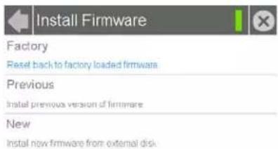
FIG. 47 Install Firmware page
| Install Firmware Page | |
| Back: Click the left-facing arrow to return to the previous page. | |
| Connection Status: | A green bar signifies that the panel has an active connection to the Master. |
| Close: | Click the "X" button to shut the Settings page and return to the main display. |
| Factory: | Select this to revert the panel back to its original factory-loaded firmware. |
| Previous: | Select this to re-install the last previously loaded firmware version. |
| New: | Select this to install new firmware from an external disk, such as from a USB stick.NOTE: if the panel does not detect an external disk containing firmware, this will be greyed out. |
Resetting to Factory-Installed Firmware
In certain circumstances, it may be necessary to uninstall the current firmware on a touch panel and return the panel to its original factory default firmware. To reset the touch panel to its original factory firmware via the Settings pages:
-
From the Install Firmware page, select the Factory field.
-
A System Message window appears, asking "Are you sure you want to install the following firmware?", with the version "Factory Firmware" listed below (FIG. 48).
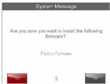
FIG. 48 Install Factory Firmware system message
-
Within five seconds, the Yes button will be enabled. At that time, select Yes to install the factory firmware and No to return to the Install Firmware page.
-
If you choose Yes, the touch panel will reboot and restart with the factory default firmware.
To reset the touch panel to its original factory firmware from the panel bootup:
- Immediately after the touch panel boots up, the device's splash page appears on the screen (FIG. 49). Press the three indicator dots within the first three seconds, before they start moving, to reset the firmware.

Press these three dots to reset the panel to its original factory firmware
FIG. 49 Modero S Series splash page
- The new confirmation page informs you that a panel reset to its original factory firmware may result in a loss of data (FIG. 50). Click Yes to confirm that you wish to continue the resetting process and click No to return to the splash page.
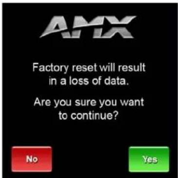
FIG. 50 Factory Reset confirmation page
- The touch panel will now reset to its original factory firmware and restart.

Resetting the touch panel to its original factory firmware will remove all previous changes to the Settings pages.
Installing Previous Firmware
In certain circumstances, it may be necessary to revert to a previously installed version of the touch panel firmware. To reset the touch panel to its previously installed firmware via the Settings pages:
- From the Install Firmware page, select the Previous field.
- A System Message window appears, asking "Are you sure you want to install the following firmware?", with the previous firmware version listed below (FIG. 51).
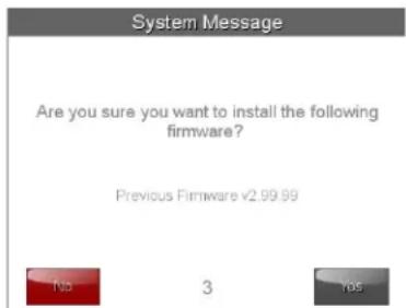
FIG. 51 Install Previous Firmware system message
- Within five seconds, the Yes button will be enabled. At that time, select Yes to install the previous firmware version and No to return to the Install Firmware page.
- If you choose Yes, the touch panel will reboot and restart with the previously installed firmware.
Installing New Firmware From An External USB Stick
To install new firmware to the touch panel from an external disk via the Settings pages:
- Download the latest Modero S Series touch panel firmware from www.amx.com and save it to a USB stick.

The firmware must be saved in a folder in the USB stick directory, corresponding with the touch panel model, in order to be recognized by the touch panel. For instance, firmware for an MST-431 must be saved in a folder named "mst-431" to be recognized by the panel. The folder name is not case sensitive.
- Insert the USB stick into an available USB port. This may require disassembling wall-mounted touch panels to access the USB ports if a USB extension was not already installed.

In the case of the MSD-431-L, connecting a USB stick to the device will require the use of a USB OTG adaptor.
- From the Install Firmware page, select the New field.
- A System Message window appears, asking "Are you sure you wish to install the following firmware?". The option to choose Yes will be enabled after five seconds. Press Yes to load the firmware listed, and No to return to the Firmware Installation popup window.
- The device will now upload the new firmware after prompting you to remove the USB stick. It will then automatically reboot.
To install new firmware to the touch panel from an external USB stick from the panel bootup:
- Before starting, download the firmware .kit file to a USB stick and connect the USB stick to the touch panel's USB A port.

For more information on updating firmware for your touch panel, particularly concerning the format and the directory placement of the firmware upgrade, please refer to the Upgrading Firmware section of the touch panel's Operation Reference Guide. The Operation Reference Guides for the Modero S Series touch panels are available at www.amx.com.
- Reboot the touch panel. When the touch panel restarts, the device will detect the firmware upgrade and display a screen requesting that you touch the screen to initiate an update (FIG. 52). If you do not touch the screen within three seconds, the firmware update will not be initiated and the panel will boot up normally (FIG. 53).
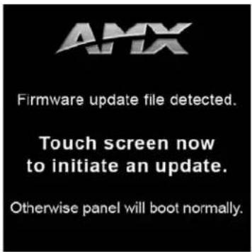
FIG. 52 Update initiation screen
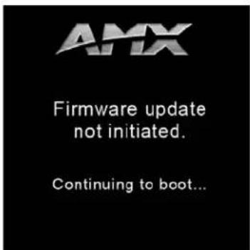
FIG. 53 Firmware Not Initiated screen
- After pressing the screen to initiate the update, a new screen appears, informing you that the upgrade is in progress (FIG. 54).

FIG. 54 Upgrade In Progress screen
-
Once the upgrade is complete, the touch panel will automatically reboot with the new firmware.
-
You may remove the USB stick from the USB A port once the dots in the splash page (FIG. 49) start moving. If you do not remove the USB stick, the update initiation screen will appear again. At this point, do not touch the screen, and the reboot will continue.
SIP
The options on the SIP page (FIG. 55) enable you to establish network settings for using your touch panel as an IP phone. With a CSG SIP Communications Gateway (FG2182-01, -02, -03), you can use your touch panel to make and receive local, long distance, and international phone calls, and have access to phone features like call waiting, caller ID, call forwarding, call queuing, and voice mail. Setting up your touch panel as a telephone requires that you set it up as one in the CSG SIP Communications Gateway. Refer to the CSG SIP Communications Gateway Operation/Reference Guide for information on setting up your touch panel to work as a telephone.
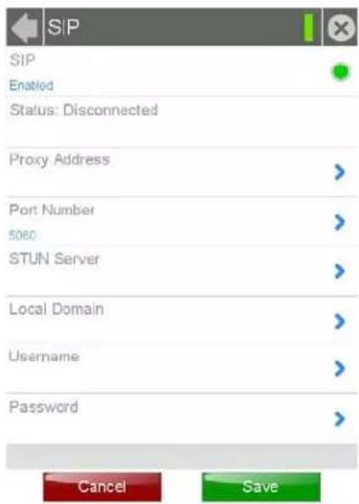
FIG. 55 SIP page
You may need to load a Duet module to enable the touch panel to receive SIP calls. The Duet module translates between the standard interface and the device protocol. It parses the buffer for responses from the device, sends strings to control the device, and receives commands from the UI module or telnet sessions. Refer to the documentation supplied with the Duet Module for more details.

NOTE
A sample UI module is provided in the module package. It is not intended to cover every possible application, but can be expanded as needed by a dealer to meet the requirements of a particular installation.
| SIP Page | |
| Back: Click the left-facing arrow to return to the previous page. | |
| Connection Status: | A green bar signifies that the panel has an active connection to the Master. |
| Close: | Click the "X" button to shut the Settings page and return to the main display. |
| SIP: | This option enables the SIP Stack on startup. If you disable this option, the panel will not attempt to read the rest of the configuration and will not register with a proxy server. However, point-to-point SIP will still be enabled allowing for existing intercom functionality. |
| Status: | This option displays whether you are connected to the proxy server. |
| Proxy Address: | This option enables you to enter the IP address or DNS name of the proxy server used as the SIP gateway. |
| Port Number: | The option displays the port you use to connect to the proxy server. The standard SIP port is 5060, but some providers use different ports. |
| STUN Server: This option | enables you to enter the IP address or DNS name of the Simple Traversal of UDP through NATs (STUN) server. This field is optional. |
| Local Domain: This is the realm used for authentication. This field is optional. | |
| Username: | This option enables you to enter the user name used for authentication to the proxy server. Normally, the user name is the same as the phone number assigned to the extension you are using. This field is optional. |
| SIP Page (Cont.) | |
| Password: | This option enables you to enter the password for the user at the proxy server. This field is optional. |
| Cancel: | Press the Cancel button to return to the Configuration page without saving any changes made on the SIP page. |
| Save: | Touch the Save button to save the changes and return to the Configuration page. |
Changing the SIP Proxy Address
To change the SIP proxy address:
- From the SIP page, select the Port Number field to open the SIP Proxy Address keyboard (FIG. 56).
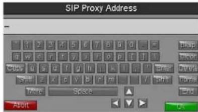
FIG. 56 SIP Proxy Address keyboard
- Enter the new proxy address and click OK.
- Click Save to save your changes to the SIP page and return to the Configuration page.
Changing the SIP Port Number
To change the port number used by the proxy server:
- From the SIP page, select the Port Number field to open the SIP Port Number keypad (FIG. 57).
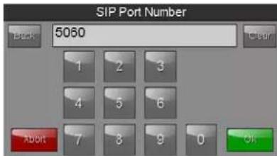
FIG. 57 SIP Port Number keypad
- Enter the new port number and click OK.
- The SIP page will now display the new SIP port number in the Port Number field.
- Click Save to save your changes to the SIP page and return to the Configuration page.
Changing the SIP STUN Address
To change the STUN address:
- From the SIP page, select the STUN Server field to open the SIP STUN Address keyboard (FIG. 58).
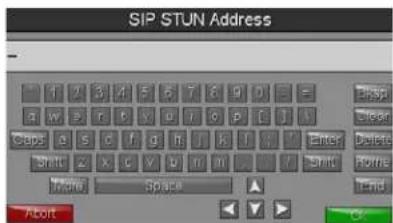
FIG. 58 SIP STUN Address Keyboard
- Enter the STUN server address and click OK.
- Click Save to save your changes to the SIP page and return to the Configuration page.
Advanced Config
The Advanced Config page (FIG. 59) displays options for more advanced configuration options, such as running diagnostics or modifying the options for streaming video.
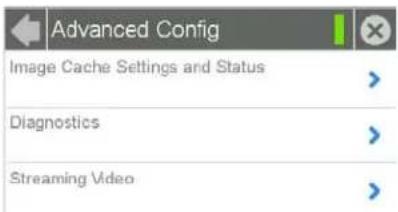
FIG. 59 Advanced Config page
| Advanced Config Page | |
| Back: Click the left-facing | arrow to return to the previous page. |
| Connection Status: | A green bar signifies that the panel has an active connection to the Master. |
| Close: | Click the “X” button to shut the Settings page and return to the main display. |
| Image Cache Settings and Status: | Select this to open the Cache Settings page (page 40) |
| Diagnostics: | Select this to open the Diagnostics page (page 41). |
| Streaming Video: | Select this to open the Streaming Video page (page 43). |
Cache Settings
The options on the Cache Settings page (FIG. 60) allow setting and clearing of the flash memory cache, as well as viewing the status of the current cache settings. The G4 graphics engine caches images to decrease load time of previously viewed images. RAM caching is always enabled, and both static and dynamic images are stored in the RAM cache as they are viewed. The size of RAM cache is automatically configured to take into account available memory versus memory that may be needed by the panel later. As the RAM cache approaches its maximum size, the oldest items in the cache may be discarded to make room for newer items. If Flash caching is enabled, dynamic images that would have been discarded will actually be moved to Flash, since retrieving images on Flash is typically faster than across a network, although it is slower than using a RAM cache. Note that since static images are already stored on Flash, they are never moved to the Flash cache, so Flash caching applies only to dynamic images. Images in Flash cache are moved back to RAM cache the next time they are viewed. As the Flash cache approaches its maximum size, the least recently used items may be discarded to make room for new items.
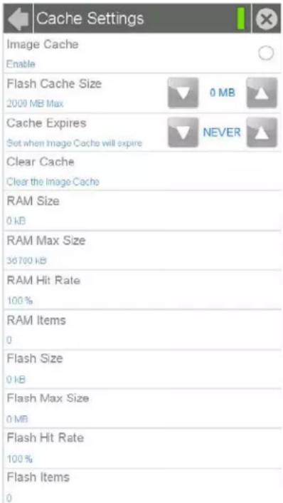
FIG. 60 Cache Settings page
| Cache Settings Page | |
| Back: Click the left-facing arrow to return to the previous page. | |
| Connection Status: | A green bar signifies that the panel has an active connection to the Master. |
| Close: | Click the “X” button to shut the Settings page and return to the main display. |
| Image Cache: Click this button to enable or disable the image Flash cache. | |
| Flash Cache Size: | Use the Up/Down buttons to increase or decrease the total size of the flash memory cache. The maximum size is displayed in this field. |
| Cache Expires: | Use the Up/Down buttons to control the amount of time elapsed before the panel automatically deletes its cache, with increments of 2 hours, 8 hours, 1 day, 2 days, 5 days, and “NEVER”. |
| Clear Cache: | Clears all files previously stored in the flash and RAM memory caches. |
| RAM Size: Displays the current size of RAM-cached items. | |
| RAM Max Size: | Displays the maximum RAM size for this panel before the least recently used items are discarded. |
| RAM Hit Rate: | The percentage of recent image requests satisfied by accessing the RAM cache. |
| RAM Items: The total number of cached images in the RAM cache. | |
| Cache Settings Page (Cont.) | |
| Flash Size: The size of the | current Flash cache contents. |
| Flash Max Size: The maximum size allocated to the Flash cache. | |
| Flash Hit Rate: | The percentage of dynamic image requests not satisfied by accessing the RAM cache, but satisfied by accessing the Flash cache. |
| Flash Items: The total number of cached images in the Flash cache. | |
Diagnostics
The Diagnostics page (FIG. 61) allows access to panel logs, network statistics, ICSP statistics, and the panel connection utility.
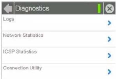
FIG. 61 Diagnostics page
| Diagnostics Page | |
| Back: Click the left-facing | arrow to return to the previous page. |
| Connection Status: | A green bar signifies that the panel has an active connection to the Master. |
| Close: | Click the "X" button to shut the Settings page and return to the main display. |
| Logs: | Click this button to open the Logs page (page 41). |
| Network Statistics: | Click this button to open the Network Statistics page (page 42). |
| ICSP Statistics: | Click this button to open the ICSP Statistics page (page 42). |
| Connection Utility: | Click this button to open the Connection Utility page (page 43). |
Logs
The Logs page (FIG. 62) chronicles all previous connections between the device and the network.
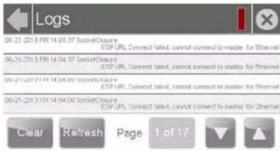
FIG. 62 Logs page
| Logs Page | |
| Back: Click the left-facing arrow to return to the previous page. | |
| Connection Status: | A green bar signifies that the panel has an active connection to the Master. |
| Close: | Click the "X" button to shut the Settings page and return to the main display. |
| Clear: Clears all connection logs. | |
| Refresh: Refreshes displayed log information. | |
| Page: | Displays the current log page number. Use the Up/Down arrows to select log pages. |
Network Statistics
The Network Statistics page (FIG. 63) displays received and transmitted IP packets. Touch the Refresh button to return the counters to their placement before the latest update.
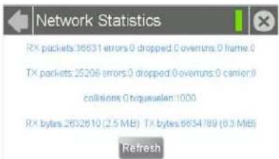
FIG. 63 Network Statistics page
| Network Statistics Page | |
| Back: Click the left-facing arrow to return to the previous page. | |
| Connection Status: | A green bar signifies that the panel has an active connection to the Master. |
| Close: | Click the "X" button to shut the Settings page and return to the main display. |
| Refresh: Refreshes all data on this page. | |
ICSP Statistics
The ICSP Statistics page (FIG. 64) collects the number of ICSP messages received by the touch panel.
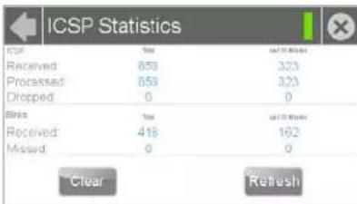
FIG. 64 ICSP Statistics page
| ICSP Statistics Page | |
| Back: Click the left-facing arrow to return to the previous page. | |
| Connection Status: | A green bar signifies that the panel has an active connection to the Master. |
| Close: | Click the "X" button to shut the Settings page and return to the main display. |
| ICSP: | |
| Received: Lists the number of ICSP messages received since the last time the page was cleared or refreshed, or within the last 15 minutes. | |
| Processed: Lists the number of ICSP messages processed since the last time the page was cleared or refreshed, or within the last 15 minutes. | |
| Dropped: Lists the number of ICSP messages dropped since the last time the page was cleared or refreshed, or within the last 15 minutes. | |
| Blinks: | |
| Received: Lists the number of blink messages received since the last time the page was cleared or refreshed, or within the last 15 minutes. | |
| Missed: Lists the number of blink messages missed since the last time the page was cleared or refreshed, or within the last 15 minutes. | |
| Clear: Clears all fields. | |
| Refresh: Refreshes all data. | |
Connection Utility
The Connection Status page (FIG. 65) displays the current connection information, including the latest Master and panel IP address information.
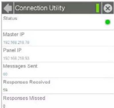
FIG. 65 Connection Utility page
| Connection Utility Page | |
| Back: Click the left-facing | arrow to return to the previous page. |
| Connection Status: | A green bar signifies that the panel has an active connection to the Master. |
| Close: | Click the “X” button to shut the Settings page and return to the main display. |
| Status: Click this button to | enable the Connection Utility page. |
| Master IP: The IP address | for the network’s Master. |
| Panel IP: The IP address used by the device. | |
| Messages Sent: Lists the number of queries sent to the Master. | |
| Responses Received: | Lists the number of responses received from the Master. |
| Responses Missed: Lists the number of responses missed by the Master. | |
Streaming Video
The Streaming Video page (FIG. 66) is used to preview video sources, such as those coming through an MXA-MP or MXA-MPL. For more information on these devices, please refer to the MXA-MP/MPL Operation Reference Guide, available at www.amx.com..
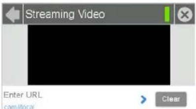
FIG. 66 Streaming Video page
| Streaming Video Page | |
| Back: Click the left-facing | arrow to return to the previous page. |
| Connection Status: | A green bar signifies that the panel has an active connection to the Master. |
| Close: | Click the "X" button to shut the Settings page and return to the main display. |
| Enter URL: | Select this to enter the URL for the video stream to be displayed. The default is the touch panel's camera, if applicable. |
| Clear URL: Select this to clear the current streaming video URL being displayed. | |
Entering a Streaming Video URL
To enter a URL for a video stream:
- From the Streaming Video page, select Enter URL to open the Set URL keyboard (FIG. 67).
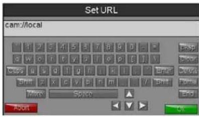
FIG. 67 Set URL keyboard
- Enter the URL for the camera and click OK.
- The camera feed will now appear in the Streaming Video page window.
Programming
Overview
You can program Modero S Series touch panels, using the commands in this section, to perform a wide variety of operations using Send Commands and variable text commands.
A device must first be defined in the NetLinx programming language with values for the Device: Port: System (in all programming examples - Panel is used in place of these values and represents all Modero panels).

Verify you are using the latest NetLinx Master and Modero S Series firmware, as well as the latest version of NetLinx Studio and TPDesign.

Future firmware updates may not support certain commands, and these commands are identified as such within each section. If you are having conflicts within a network or device, or within NetLinx Studio, check the command to verify that this command is no longer supported within the currently used firmware version.
Page Commands
These Page Commands are used in NetLinx Programming Language and are case insensitive.
| Page Commands | |
| @APGAdd a specific popup page to a specified popup group. | Add the popup page to a group if it does not already exist. If the new popup is added to a group which has a popup displayed on the current page along with the new pop-up, the displayed popup will be hidden and the new popup will be displayedSyntax:"'@APG-;";" "Variable:popup page name = 1 - 50 ASCII characters. Name of the popup page.popup group name = 1 - 50 ASCII characters. Name of the popup group.Example:SEND_COMMAND Panel,"'@APG-Popup1;Group1'"Adds the popup page 'Popup1' to the popup group 'Group1'.NOTE: Future firmware versions may not support this command. |
| @CPGClear all popup pages from specified popup group. | Syntax:"'@CPG-";" "Variable:popup group name = 1 - 50 ASCII characters. Name of the popup group.Example:SEND_COMMAND Panel,"'@CPG-Group1'"Clears all popup pages from the popup group 'Group1'.NOTE: Future firmware versions may not support this command. |
| @DPGDelete a specific popup page from specified popup group if it exists. | Syntax:"'@DPG-;";" "Variable:popup page name = 1 - 50 ASCII characters. Name of the popup page.popup group name = 1 - 50 ASCII characters. Name of the popup group.Example:SEND_COMMAND Panel,"'@DPG-Popup1;Group1'"Deletes the popup page 'Popup1' from the popup group 'Group1'.NOTE: Future firmware versions may not support this command. |
| Page Commands (Cont.) | |
| @PDRSet the popup location reset flag. | If the flag is set, the popup will return to its default location on show instead of its last drag location Syntax:"'@PDR-;""Variable:popup page name = 1 - 50 ASCII characters. Name of the page the popup is displayed On.reset flag = 1 = Enable reset flag0 = Disable reset flagExample:SEND_COMMAND Panel,"'@PDR-Popup1;1'"Popup1 will return to its default location when turned On.NOTE:Future firmware versions may not support this command. |
| @PHESet the hide effect for the specified popup page to the named hide effect. | Syntax:"'@PHE-;""Variable:popup page name = 1 - 50 ASCII characters. Name of the page the popup is displayed On.hide effect name = Refers to the popup effect names being used.Example:SEND_COMMAND Panel,"'@PHE-Popup1;Slide to Left'"Sets the Popup1 hide effect name to 'Slide to Left'.NOTE:Future firmware versions may not support this command. |
| @PHPSet the hide effect position. | Only 1 coordinate is ever needed for an effect; however, the command will specify both. This command sets the location at which the effect will end at Syntax:"'@PHP-;","Variable:popup page name = 1 - 50 ASCII characters. Name of the page the popup is displayed On.Example:SEND_COMMAND Panel,"'@PHP-Popup1;75,0'"Sets the Popup1 hide effect x-coordinate value to 75 and the y-coordinate value to 0.NOTE:Future firmware versions may not support this command. |
| @PHTSet the hide effect time for the specified popup page. | Syntax:"'@PHT-;""Variable:popup page name = 1 - 50 ASCII characters. Name of the page the popup is displayed On.hide effect time = Given in 1/10ths of a second.Example:SEND_COMMAND Panel,"'@PHT-Popup1;50'"Sets the Popup1 hide effect time to 5 seconds.NOTE:Future firmware versions may not support this command. |
| @PPAClose all popups on a specified page. | If the page name is empty, the current page is used. Same as the 'Clear Page' command in TPDesign4 Syntax:"'@PPA-''Variable:page name = 1 - 50 ASCII characters. Name of the page the popup is displayed On.Example:SEND_COMMAND Panel,"'@PPA-Page1'"Close all pop-ups on Page1.NOTE:Future firmware versions may not support this command. |
| @PPFDeactivate a specific popup page on either a specified page or the current page. | If the page name is empty, the current page is used (see example 2). If the popup page is part of a group, the whole group is deactivated. This command works in the same way as the 'Hide Popup' command in TPDesign4 Syntax:"'@PPF-;;""Variable:popup page name = 1 - 50 ASCII characters. Name of the popup page.page name = 1 - 50 ASCII characters. Name of the page the popup is displayed On.Example:SEND_COMMAND Panel,"'@PPF-Popup1;Main'"Example 2:SEND_COMMAND Panel,"'@PPF-Popup1'"Deactivates the popup page 'Popup1' on the current page.NOTE:Future firmware versions may not support this command. |
| @PPGToggle a specific popup page on either a specified page or the current page. | If the page name is empty, the current page is used (see example 2). Toggling refers to the activating/deactivating (On/Off) of a popup page. This command works in the same way as the 'Toggle Popup' command in TPDesign4 Syntax:"'@PPG-;;""Variable:popup page name = 1 - 50 ASCII characters. Name of the popup page.page name = 1 - 50 ASCII characters. Name of the page the popup is displayed On.Example:SEND_COMMAND Panel,"'@PPG-Popup1;Main'"Toggles the popup page 'Popup1' on the 'Main' page from one state to another (On/Off).Example 2:SEND_COMMAND Panel,"'@PPG-Popup1'"Toggles the popup page 'Popup1' on the current page from one state to another (On/Off).NOTE:Future firmware versions may not support this command. |
| @PPKKill a specific popup page from all pages. | Kill refers to the deactivating (Off) of a popup window from all pages. If the pop-up page is part of a group, the whole group is deactivated. This command works in the same way as the 'Clear Group' command in TPDesign 4 Syntax:"'@PPK-!""Variable:popup page name = 1 - 50 ASCII characters. Name of the popup page.Example:SEND_COMMAND Panel,"'@PPK-Popup1'"Kills the popup page 'Popup1' on all pages.NOTE:Future firmware versions may not support this command. |
| @PPMSet the modality of a specific popup page to Modal or NonModal. | A Modal popup page, when active, only allows you to use the buttons and features on that popup page. All other buttons on the panel page are inactivated.Syntax:"'@PPM-;''Variable:popup page name = 1 - 50 ASCII characters. Name of the popup page.mode = NONMODAL converts a previously Modal popup page to a NonModal.MODAL converts a previously NonModal popup page to Modal. modal = 1 and non-modal = 0Example:SEND_COMMAND Panel,"'@PPM-Popup1;Modal'Sets the popup page 'Popup1' to Modal. SEND_COMMAND Panel,"'@PPM-Popup1;1'"Sets the popup page 'Popup1' to Modal.NOTE: Future firmware versions may not support this command. |
| @PPNActivate a specific popup page to launch on either a specified page or the current page. | If the page name is empty, the current page is used (see example 2). If the popup page is already on, do not re-draw it. This command works in the same way as the 'Show Popup' command in TPDesign4.Syntax:"'@PPN-;''Variable:popup page name = 1 - 50 ASCII characters. Name of the popup page.page name = 1 - 50 ASCII characters. Name of the page the popup is displayed On.Example:SEND_COMMAND Panel,"'@PPN-Popup1;Main'"Activates 'Popup1' on the 'Main' page.Example 2:SEND_COMMAND Panel,"'@PPN-Popup1'"Activates the popup page 'Popup1' on the current page.NOTE: Future firmware versions may not support this command. |
| @PPTSet a specific popup page to timeout within a specified time. | If timeout is empty, popup page will clear the timeout.Syntax:"'@PPT-;''Variable:popup page name = 1 - 50 ASCII characters. Name of the popup page.timeout = Timeout duration in 1/10ths of a second.Example:SEND_COMMAND Panel,"'@PPT-Popup1;30'"Sets the popup page 'Popup1' to timeout within 3 seconds.NOTE: Future firmware versions may not support this command. |
| @PPXClose all popups on all pages. | This command works in the same way as the 'Clear All' command in TPDesign 4.Syntax:"'@PPX'"Example:SEND_COMMAND Panel,"'@PPX'"Close all popups on all pages.NOTE: Future firmware versions may not support this command. |
| @PSESet the show effect for the specified popup page to the named show effect. | Syntax:"'@PSE-;""Variable:popup page name = 1 - 50 ASCII characters. Name of the page the popup is displayed On.show effect name = Refers to the popup effect name being used.Example:SEND_COMMAND Panel,"'@PSE-Popup1;Slide from Left'"Sets the Popup1 show effect name to 'Slide from Left'.NOTE:Future firmware versions may not support this command. |
| @PSPSet the show effect position. | Only 1 coordinate is ever needed for an effect; however, the command will specify both.This command sets the location at which the effect will begin Syntax:"'@PSP-;","Variable:popup page name = 1 - 50 ASCII characters. Name of the page the popup is displayed On.Example:SEND_COMMAND Panel,"'@PSP-Popup1;100,0'"Sets the Popup1 show effect x-coordinate value to 100 and the y-coordinate value to 0.NOTE:Future firmware versions may not support this command. |
| @PSTSet the show effect time for the specified popup page. | Syntax:"'@PST-;""Variable:popup page name = 1 - 50 ASCII characters. Name of the page the popup is displayed On.show effect time = Given in 1/10ths of a second.Example:SEND_COMMAND Panel,"'@PST-Popup1;50'"Sets the Popup1 show effect time to 5 seconds.NOTE:Future firmware versions may not support this command. |
| PAGEFlip to a specified page. | Flips to a page with a specified page name. If the page is currently active, it will not redraw the page.Syntax:"'PAGE-";"Variable:page name = 1 - 50 ASCII characters. Name of the page is displayed On. If left blank, the page flips back to the previous page.Example:SEND_COMMAND Panel,"'PAGE-Papel'"Flips to page1.SEND_COMMAND Panel,"'PAGE-'Flips to the previous page.NOTE:Future firmware versions may not support this command. |
| PPOFDeactivate a specific popup page on either a specified page or the current page. | If the page name is empty, the current page is used (see example 2). If the popup page is part of a group, the whole group is deactivated. This command works in the same way as the 'Hide Popup' command in TPDesign4 Syntax:"'PPOF-;""Variable:popup page name = 1 - 50 ASCII characters. Name of the popup page.page name = 1 - 50 ASCII characters. Name of the page the popup is displayed On.Example:SEND_COMMAND Panel,"'PPOF-Popup1;Main'"Deactivates the popup page 'Popup1' on the Main page.Example 2:SEND_COMMAND Panel,"'PPOF-Popup1'"Deactivates the popup page 'Popup1' on the current page.NOTE:Future firmware versions may not support this command. |
| PPOGToggle a specific popup page on either a specified page or the current page. | If the page name is empty, the current page is used (see example 2). Toggling refers to the activating/deactivating (On/Off) of a popup page. This command works in the same way as the 'Toggle Popup' command in TPDesign4Syntax:"'PPOG-;""Variable:popup page name = 1 - 50 ASCII characters. Name of the popup page.page name = 1 - 50 ASCII characters. Name of the page the popup is displayed On.Example:SEND_COMMAND Panel,"'PPOG-Popup1;Main'"Toggles the popup page 'Popup1' on the Main page from one state to another (On/Off).Example 2:SEND_COMMAND Panel,"'PPOG-Popup1'"Toggles the popup page 'Popup1' on the current page from one state to another (On/Off).NOTE:Future firmware versions may not support this command. |
| PPONActivate a specific popup page to launch on either a specified page or the current page. | If the page name is empty, the current page is used (see example 2). If the popup page is already On, do not re-draw it. This command works in the same way as the 'Show Popup' command in TPDesign4Syntax:"'PPON-;""Variable:popup page name = 1 - 50 ASCII characters. Name of the popup page.page name = 1 - 50 ASCII characters. Name of the page the popup is displayed On.Example:SEND_COMMAND Panel,"'PPON-Popup1; Main'"Activates the popup page 'Popup1' on the Main page.Example 2:SEND_COMMAND Panel,"'PPON-Popup1'"Activates the popup page 'Popup1' on the current page.NOTE:Future firmware versions may not support this command. |
Programming Numbers
The following information provides the programming numbers for colors, fonts, and borders.
Colors can be used to set the colors on buttons, sliders, and pages. The lowest color number represents the lightest color-specific display; the highest number represents the darkest display. For example, 0 represents light red, and 5 is dark red.
RGB Triplets and Names For Basic 88 Colors
| RGB Values for all 88 Basic Colors | ||||
| Index No. | Name Red Green Blue | |||
| 00 Very Light Red 255 0 0 | ||||
| 01 Light Red 223 0 0 | ||||
| 02 Red 191 0 0 | ||||
| 03 Medium Red 159 0 0 | ||||
| 04 Dark Red 127 0 0 | ||||
| 05 Very Dark Red 95 0 0 | ||||
| 06 Very Light Orange | 255 | 128 | 0 | |
| 07 Light Orange | 223 | 112 | 0 | |
| 08 Orange | 191 96 | 0 | ||
| 09 Medium Orange | 159 80 | 0 | ||
| 10 Dark Orange | 127 64 | 0 | ||
| 11 Very Dark Orange | 95 48 | 0 | ||
| 12 Very Light Yellow | 255 | 255 | 0 | |
| 13 Light Yellow | 223 | 223 | 0 | |
| 14 Yellow | 191 | 191 | 0 | |
| 15 Medium Yellow | 159 | 159 | 0 | |
| 16 Dark Yellow | 127 | 127 | 0 | |
| 17 Very Dark Yellow | 95 95 | 0 | ||
| 18 Very Light Lime | 128 | 255 | 0 | |
| 19 Light Lime | 112 | 223 | 0 | |
| 20 Lime | 96 191 | 0 | ||
| 21 Medium Lime | 80 159 | 0 | ||
| 22 Dark Lime 64 127 0 | ||||
| 23 Very Dark Lime 48 95 0 | ||||
| 24 Very Light Green | 0 255 | 0 | ||
| 25 Light Green | 0 223 | 0 | ||
| 26 Green | 0 191 | 0 | ||
| 27 Medium Green | 0 159 | 0 | ||
| 28 Dark Green | 0 127 | 0 | ||
| 29 Very Dark Green | 0 | 95 | 0 | |
| 30 Very Light Mint | 0 255 | 128 | ||
| 31 Light Mint | 0 223 | 112 | ||
| 32 Mint | 0 191 | 96 | ||
| 33 Medium Mint | 0 159 | 80 | ||
| 34 Dark Mint | 0 127 | 64 | ||
| 35 Very Dark Mint | 0 | 95 | 48 | |
| 36 Very Light Cyan | 0 255 | 255 | ||
| 37 Light Cyan 0 223 223 | ||||
| RGB Values for all 88 Basic Colors (Cont.) | ||||
| Index No. | Name Red Green Blue | |||
| 38 Cyan | 0 191 191 | |||
| 39 Medium | Cyan 0 159 159 | |||
| 40 Dark | Cyan 0 127 127 | |||
| 41 Very | Dark Cyan 0 95 95 | |||
| 42 Very | Light Aqua 0 128 255 | |||
| 43 Light | Aqua 0 112 223 | |||
| 44 Aqua | 0 96 191 | |||
| 45 Medium | Aqua 0 80 159 | |||
| 46 Dark | Aqua 0 64 127 | |||
| 47 Very | Dark Aqua 0 48 95 | |||
| 48 Very | Light Blue 0 | 0 | 0 255 | |
| 49 Light | Blue 0 | 0 | 0 223 | |
| 50 Blue | 0 | 0 191 | ||
| 51 Medium | Blue 0 | 0 | 0 159 | |
| 52 Dark | Blue 0 | 0 | 0 127 | |
| 53 Very | Dark Blue 0 | 0 | 0 95 | |
| 54 Very | Light Purple 128 0 255 | |||
| 55 Light | Purple 112 0 223 | |||
| 56 Purple | 96 0 191 | |||
| 57 Medium | Purple 80 0 159 | |||
| 58 Dark | Purple 64 0 127 | |||
| 59 Very | Dark Purple 48 0 | 95 | ||
| 60 Very | Light Magenta 255 0 255 | |||
| 61 Light | Magenta 223 0 223 | |||
| 62 Magenta | 191 0 191 | |||
| 63 Medium | Magenta 159 0 159 | |||
| 64 Dark | Magenta 127 0 127 | |||
| 65 Very | Dark Magenta 95 0 | 95 | ||
| 66 Very | Light Pink 255 0 128 | |||
| 67 Light | Pink 223 0 | 112 | ||
| 68 Pink | 191 0 | 96 | ||
| 69 Medium | Pink 159 0 | 80 | ||
| 70 Dark | Pink 127 0 | 64 | ||
| 71 Very | Dark Pink 95 0 | 48 | ||
| 72 White | 255 | 255 255 | ||
| 73 Grey1 | 238 | 238 238 | ||
| 74 Grey3 | 204 | 204 204 | ||
| 75 Grey5 | 170 | 170 170 | ||
| 76 Grey7 | 136 | 136 136 | ||
| 77 Grey9 | 102 | 102 102 | ||
| 78 Grey4 | 187 | 187 187 | ||
| 79 Grey6 | 153 | 153 153 | ||
| 80 | Grey8 | 119 | 119 119 | |
| 81 Grey10 | 85 85 85 | |||
| 82 Grey1 | 2 51 51 51 | |||
| 83 Grey1 | 3 34 34 34 | |||
| 84 Grey2 | 221 221 221 | |||
| 85 Grey1 | 1 68 68 68 | |||
| 86 Grey1 | 4 17 17 17 | |||
| 87 Black | 0 0 0 | |||
| 255 | TRANSPARENT | 99 53 99 | ||
Font Styles And ID Numbers
Font styles can be used to program the text fonts on buttons, sliders, and pages. The following chart shows the default font type and their respective ID numbers generated by TPDesign4.
| Default Font Styles and ID Numbers | ||||||
| Font ID # | Font type | Size | Font ID # | Font type | Size | |
| 1 | Courier New | 9 | 19 | Arial | 9 | |
| 2 | Courier New | 12 | 20 | Arial | 10 | |
| 3 | Courier New | 18 | 21 | Arial | 12 | |
| 4 | Courier New | 26 | 22 | Arial | 14 | |
| 5 | Courier New | 32 | 23 | Arial | 16 | |
| 6 | Courier New | 18 | 24 | Arial | 18 | |
| 7 | Courier New | 26 | 25 | Arial | 20 | |
| 8 | Courier New | 34 | 26 | Arial | 24 | |
| 9 | AMX Bold | 14 | 27 | Arial | 36 | |
| 10 | AMX Bold | 20 | 28 | Arial Bold | 10 | |
| 11 | AMX Bold | 36 | 29 | Arial Bold | 8 | |
| 32 - Variable Fonts start at 32. | ||||||

Fonts must be imported into a TPDesign4 project file. The font ID numbers are assigned by TPDesign4. These values are also listed in the Generate Programmer's Report.
Border Styles And Programming Numbers
Border styles can be used to program borders on buttons, sliders, and popup pages.
| Border Styles and Programming Numbers | |||
| No. B | order styles | No. B | border styles |
| 0-1 | No border | 10-11 | Picture frame |
| 2 | Single line | 12 | Double line |
| 3 | Double line | 20 | Bevel-S |
| 4 | Quad line | 21 | Bevel-M |
| 5-6 | Circle 15 | 22-23 | Circle 15 |
| 7 | Single line | 24-27 | Neon inactive-S |
| 8 | Double line | 40-41 | Diamond 55 |
| 9 | Quad line | ||
The TPDesign4 Touch Panel Design program has pre-set border styles that are user-selectable.
The following number values cannot be used for programming purposes when changing border styles. TPDesign border styles may ONLY be changed by using the name.
| TPDesign Border Styles by Name | |||
| No. Border styles No. Border styles | |||
| 1 None | 27 Cursor Bottom | ||
| 2 AMX | Elite -L 28 Cursor Bottom with Hole | ||
| 3 AMX | Elite -M 29 Cursor Top | ||
| 4 AMX | Elite -S 30 Cursor Top with Hole | ||
| 5 Beve | -L 31 Cursor Left | ||
| 6 Beve | -M 32 Cursor Left with Hole | ||
| 7 Beve | -S 33 Cursor Right | ||
| 8 Circle | 15 34 Cursor Right with Hole | ||
| 9 Circle | 25 35 Custom Frame | ||
| 10 Circle | 35 36 Diamond 15 | ||
| 11 Circle | 45 37 Diamond 25 | ||
| 12 Circle | 55 38 Diamond 35 | ||
| 13 Circle | 65 39 Diamond 45 | ||
| 14 Circle | 75 40 Diamond 55 | ||
| 15 Circle | 85 41 Diamond 65 | ||
| 16 Circle | 95 42 Diamond 75 | ||
| 17 Circle | 105 | 43 Diamond | 85 |
| 18 Circle | 115 | 44 Diamond | 95 |
| 19 Circle | 125 | 45 Diamond | 105 |
| 20 Circle | 135 | 46 Diamond | 115 |
| 21 Circle | 145 | 47 Diamond | 125 |
| 22 Circle | 155 | 48 Diamond | 135 |
| 23 Circle | 165 | 49 Diamond | 145 |
| 24 Circle | 175 | 50 Diamond | 155 |
| 25 Circle | 185 | 51 Diamond | 165 |
| 26 Circle | 195 | 52 Diamond | 175 |
| 53 Diamond | 185 | 97 Menu Bottom Rounded 185 | |
| 54 Diamond | 195 | 98 Menu Bottom Rounded 195 | |
| 55 Double Bevel -L | 99 Menu Top Rounded 15 | ||
| 56 Double Bevel -M | 100 | Menu Top Rounded 25 | |
| 57 Double Bevel -S | 101 | Menu Top Rounded 35 | |
| 58 Double Line | 102 | Menu Top Rounded 45 | |
| 59 Fuzzy | 103 | Menu Top Rounded 55 | |
| 60 Glow-L | 104 | Menu Top Rounded 65 | |
| 61 Glow-S | 105 | Menu Top Rounded 75 | |
| 62 Help Down | 106 | Menu Top Rounded 85 | |
| 63 Neon Active -L | 107 | Menu Top Rounded 95 | |
| 64 Neon Active -S | 108 | Menu Top Rounded 105 | |
| 65 Neon Inactive -L 109 | Menu Top Rounded 115 | ||
| 66 | Neon Inactive -S | 110 | Menu Top Rounded 125 |
| 67 Oval H 60x30 | 111 | Menu Top Rounded 135 | |
| 68 | Oval H 100x50 | 112 | Menu Top Rounded 145 |
| 69 | Oval H 150x75 | 113 | Menu Top Rounded 155 |
| 70 | Oval H 200x100 | 114 | Menu Top Rounded 165 |
| TPDesign Border Styles by Name (Cont.) | |||
| No. | Border styles No. | Border styles | |
| 71 | Oval V 30x60 115 | Menu Top Rounded 175 | |
| 72 | Oval V 50x100 116 | Menu Top Rounded 185 | |
| 73 | Oval V 75x150 117 | Menu Top Rounded 195 | |
| 74 | Oval V 100x200 118 | Menu Right Rounded 15 | |
| 75 | Picture Frame 119 | Menu Right Rounded 25 | |
| 76 | Quad Line 120 | Menu Right Rounded 35 | |
| 77 | Single Line 121 | Menu Right Rounded 45 | |
| 78 | Windows Style Popup | 122 | Menu Right Rounded 55 |
| 79 | Windows Style Popup (Status Bar) | 123 | Menu Right Rounded 65 |
| 80 | Menu Bottom Rounded 15 | 124 | Menu Right Rounded 75 |
| 81 | Menu Bottom Rounded 25 | 125 | Menu Right Rounded 85 |
| 82 | Menu Bottom Rounded 35 | 126 | Menu Right Rounded 95 |
| 83 | Menu Bottom Rounded 45 | 127 | Menu Right Rounded 105 |
| 84 | Menu Bottom Rounded 55 | 128 | Menu Right Rounded 115 |
| 85 | Menu Bottom Rounded 65 | 129 | Menu Right Rounded 125 |
| 86 | Menu Bottom Rounded 75 | 130 | Menu Right Rounded 135 |
| 87 | Menu Bottom Rounded 85 | 131 | Menu Right Rounded 145 |
| 88 | Menu Bottom Rounded 95 | 132 | Menu Right Rounded 155 |
| 89 | Menu Bottom Rounded 105 | 133 | Menu Right Rounded 165 |
| 90 | Menu Bottom Rounded 115 | 134 | Menu Right Rounded 175 |
| 91 | Menu Bottom Rounded 125 | 135 | Menu Right Rounded 185 |
| 92 | Menu Bottom Rounded 135 | 136 | Menu Right Rounded 195 |
| 93 | Menu Bottom Rounded 145 | 137 | Menu Left Rounded 15 |
| 94 | Menu Bottom Rounded 155 | 138 | Menu Left Rounded 25 |
| 95 | Menu Bottom Rounded 165 | 139 | Menu Left Rounded 35 |
| 96 | Menu Bottom Rounded 175 | 140 | Menu Left Rounded 45 |
| 141 | Menu Left Rounded 55 | 149 Menu Left Rounded 135 | |
| 142 | Menu Left Rounded 65 | 150 Menu Left Rounded 145 | |
| 143 | Menu Left Rounded 75 | 151 Menu Left Rounded 155 | |
| 144 | Menu Left Rounded 85 | 152 Menu Left Rounded 165 | |
| 145 | Menu Left Rounded 95 | 153 Menu Left Rounded 175 | |
| 146 | Menu Left Rounded 105 | 154 Menu Left Rounded 185 | |
| 147 | Menu Left Rounded 115 | 155 Menu Left Rounded 195 | |
| 148 | Menu Left Rounded 125 | ||
"^^" Button Commands
These Button Commands are used in NetLinx Studio and are case insensitive.
All commands that begin with “^” have the capability of assigning a variable text address range and button state range. A device must first be defined in the NetLinx programming language with values for the Device: Port: System (in all programming examples - Panel is used in place of these values).
- Variable text ranges allow you to target 1 or more variable text channels in a single command.
- Button State ranges allow you to target 1 or more states of a variable text button with a single command.
- “.” Character is used for the 'through' notation, also the “&” character is used for the 'And' notation.
| "^" Button Commands | |
| ^ANIRun a button animation(in 1/10 second). | Syntax:"^^ANI-,,,,',''Variable:variable text address range = 1 - 4000.start state = Beginning of button state (0= current state).end state = End of button state.time = In 1/10 second intervals.Example:SEND_COMMAND Panel,"^^ANI-500,1,25,100"Runs a button animation at text range 500 from state 1 to state 25 for 10 second. |
| ^APFAdd page flip action to a button if it does not already exist. | Syntax:"^^APF-,,,,',''Variable:variable text address range = 1 - 4000.page flip action =Stan[dardPage] - Flip to standard pagePrev[iousPage] - Flip to previous pageShow[Popup] - Show Popup pageHide[Popup] - Hide Popup pageTogg[lePopup] - Toggle popup stateClearG[roup] - Clear popup page group from all pagesClearP[age] - Clear all popup pages from a page with the specified page nameClearA[ll] - Clear all popup pages from all pagespage name = 1 - 50 ASCII characters.Example:SEND COMMAND Panel,"^^APF-400,Stan,Main Page'"Assigns a button to a standard page flip with page name 'Main Page'. |
| ^BATAppendnon-unicode text. | Syntax:"^^BAT-,,,,',''Variable:variable text address range = 1 - 4000.button states range = 1 - 256 for multi-state buttons (0 = All states, for General buttons 1 = Off state and 2 = On state).new text = 1 - 50 ASCII characters.Example:SEND_COMMAND Panel,"^^BAT-520,1,Enter City'"Appends the text 'Enter City' to the button's OFF state. |
| "^" Button Commands (Cont.) | |
| ^BAUAppendunicode text. | Same format as ^UNI.Syntax:"^^BAU-,,,''Variable:variable text address range = 1 - 4000.button states range = 1 - 256 for multi-state buttons (0 = All states, for General buttons 1 = Off state and 2 = On state).unicode text = 1 - 50 ASCII characters. Unicode characters must be entered in Hex format.Example:SEND_COMMAND Panel,"^^BAU-520,1,00770062'''Appends Unicode text '00770062' to the button's OFF state. |
| ^BCBSet the border color to the specified color. | Only if the specified border color is not the same as the current color.Note: Color can be assigned by color name (without spaces), number or R,G,B value (RRGGBB or RRGGBBAA).Syntax:"^^BCB-,,,''Variable:variable text address range = 1 - 4000.button states range = 1 - 256 for multi-state buttons (0 = All states, for General buttons 1 = Off state and 2 = On state).color value = Refer to the RGB Values for all 88 Basic Colors table on page 51 for more information.Example:SEND_COMMAND Panel,"^^BCB-500.504&510,1,12''Sets the Off state border color to 12 (Yellow). Colors can be set by Color Numbers, Color name, R,G,B,alpha colors (RRGGBBAA) and R, G & B colors values (RRGGBB). |
| ^BCFSet the fill color to the specified color. | Only if the specified fill color is not the same as the current color.Note: Color can be assigned by color name (without spaces), number or R,G,B value (RRGGBB or RRGGBBAA).Syntax:"^^BCF-,,,''Variable:variable text address range = 1 - 4000.button states range = 1 - 256 for multi-state buttons (0 = All states, for General buttons 1 = Off state and 2 = On state).color value = Refer to the RGB Values for all 88 Basic Colors table on page 51 for more information.Example:SEND_COMMAND Panel,"^^BCF-500.504&510.515,1,12''SEND_COMMAND Panel,"^^BCF-500.504&510.515,1,Yellow''SEND_COMMAND Panel,"^^BCF-500.504&510.515,1,#F4EC0A63'''SEND_COMMAND Panel,"^^BCF-500.504&510.515,1,#F4EC0A''Sets the Off state fill color by color number. Colors can be set by Color Numbers, Color name, R,G,B,alpha colors (RRGGBBAA) and R, G & B colors values (RRGGBB). |
| ^BCTSet the text color to the specified color. | Only if the specified text color is not the same as the current color.Note:Color can be assigned by color name (without spaces), number or R,G,B value (RRGGBB or RRGGBBAA).Syntax:"^^BCT-,,,""Variable:variable text address range = 1 - 4000.button states range = 1 - 256 for multi-state buttons (0 = All states, for General buttons 1 = Off state and 2 = On state).color value = Refer to the RGB Values for all 88 Basic Colors table on page 51 for more information.Example:SEND_COMMAND Panel,"^^BCT-500.504&510,1,12'"Sets the Off state border color to 12 (Yellow). Colors can be set by Color Numbers, Color name, R,G,B,alpha colors (RRGGBBAA) and R, G & B colors values (RRGGBB). |
| ^BDOSet the button draw order. | Determines what order each layer of the button is drawn.Syntax:"^^BDO-,,,""Variable:variable text address range = 1 - 4000.button states range = 1 - 256 for multi-state buttons (0 = All states, for General buttons 1 = Off state and 2 = On state).layer assignments =Fill Layer = 1Image Layer = 2Icon Layer = 3Text Layer = 4Border Layer = 5Note:The layer assignments are from bottom to top. The default draw order is 12345.Example:SEND_COMMAND Panel,"^^BDO-530,1&2,51432'"Sets the button's variable text 530 ON/OFF state draw order (from bottom to top) to Border, Fill, Text, Icon, and Image.Example 2:SEND_COMMAND Panel,"^^BDO-1,0,12345'"Sets all states of a button back to its default drawing order. |
| ^BFBSet the feedback type of the button. | ONLY works on General-type buttons.Syntax:"^^BFB-,,,""Variable:variable text address range = 1 - 4000.feedback type = (None, Channel, Invert, On (Always on), Momentary, and Blink).Example:SEND_COMMAND Panel,"^^BFB-500,Momentary'"Sets the Feedback type of the button to 'Momentary'. |
| ^BIMSet the input mask for the specified address. | Syntax:"^^BIM-,",""Variable:variable text address range = 1 - 4000.input mask = Refer to the Text Area Input Masking table on page 110 for character types.Example:SEND_COMMAND Panel,"'^BIM-500,AAAAAAAAA"'Sets the input mask to ten 'A' characters, that are required, to either a letter or digit (entry is required). |
| ^BLNSet the number of lines removed equally from the top and bottom of a composite video signal. | The maximum number of lines to remove is 240. A value of 0 will display the incoming video signal unaffected. This command is used to scale non 4x3 video images into non 4x3 video buttonsSyntax:"^^BLN-,",,""Variable:variable text address range = 1 - 4000.button states range = 1 - 256 for multi-state buttons (0 = All states, for General buttons 1 = Off state and 2 = On state).number of lines = 0 - 240.Example:SEND_COMMAND Panel,"'^BLN-500,55'"Equally removes 55 lines from the top and 55 lines from the bottom of the video button. |
| ^BMCButton copy command.Copy attributes of the source button to all the destination buttons. | Note that the source is a single button state. Each state must be copied as a separate command. Thesection represents what attributes will be copied. All codes are 2 char pairs that can be separated by comma, space, percent or just ran together. Syntax:"^^BMC-,,,,,,,,,,,,,,,,,,,,,,,,,,,,,,,,,,,,,,,,,,,,,,,,,,,,,,,,,,,,,,,,,,,,,,,,,,,,,,,,,,,,,,,,,,,,,,,,,,,,,,,,,,,,,,,,,,,,,,,,,,,,,,,,,,,,,,,,,,,,,,,,,,,,,,,,,,,,,,,,,,,,,,,,,,,,,,,,,,,,,,,,,,,,,,,,,,,,,,,,, |
| ^BMFSet any/all button parameters by sending embedded codes and data. | Syntax:"|^BMF-,"NOTE: Many subcommands do not use button state information. Refer to the subcommand for details. |
| Variables:variable text address char array = 1 - 4000.button states range = 1 - 256 for multi-state buttons (0 = All states, for General buttons 1 = Off state and 2 = On state).level range = 1 - 600 (level value is 1 - 65535).Data:'%B= Set the border style name. (No support for states.)NOTE: This parameter should be always used in its own BMF command, and should not be combined with other BMF subcommands.'%B',= Set the border style number (No support for states.)'%CB= Set Border Color.'%CF= Set Fill Color.'%CT= Set Text Color.'%DO<1-5><1-5><1-5><1-5><1-5> = Set the draw order. Listed from bottom to top.'%EC= Set the text effect color.'%EF= Set the text effect.NOTE: This parameter should be always used in its own BMF command, and should not be combined with other BMF subcommands.'%EN<1 or 0'> = Enable/disable a button.'%F' = Set the font. See the Default Font Styles and ID Numbers table on page 53.'%GC= Set the bargraph slider color/Joystick cursor color.'%GD= Set the bargraph ramp down time in 1/10 second.'%GG= Set the bargraph drag increment. Refer to the ^GDI command on page 68 for more information.'%GH= Set the bargraph upper limit.'%GI' = Set the bargraph invert/noninvert or joystick coordinate (0,1,2,3).'%GL= Set the bargraph lower limit.'%GN= Set the bargraph slider name/Joystick cursor name.NOTE: This parameter should be always used in its own BMF command, and should not be combined with other BMF subcommands.'%GU= Set the bargraph ramp up time in intervals of 1/10 second.'%I',= Set the icon using values of 01 - 9900 (icon numbers are assigned in the TPDesign4 Resource Manager tab - Slots section).'%I<icon 01-9900, 0-clear'> = Set the icon using values of 01 - 9900 (icon numbers are assigned in the TPDesign4 Resource Manager tab - Slots section).'%J',= As shown the following telephone keypad alignment chart:0Zero can be used for an absolute posi | |
| ^BMF(Cont.) | "%LN<0-240>' = Set the lines of video being removed. ^BLN section on page 59 for more information.%MI<= Set the mask image. Refer to the ^BMI command on page 63 for more information.NOTE: This parameter should be always used in its own BMF command, and should not be combined with other BMF subcommands.%MK<= Set the input mask of a text area.NOTE: This parameter should be always used in its own BMF command, and should not be combined with other BMF subcommands.%ML<= Set the maximum length of a text area.%OP<0-255'> = Set the button opacity to either Invisible (value=0) or Opaque (value=255).%OP#<00-FF'> = Set the button opacity to either Invisible (value=00) or Opaque (value=FF).'%OT<= Set the Feedback (Output) Type to one of the following: None, Channel, Invert, ON (Always ON), Momentary, or Blink.NOTE: This parameter should be always used in its own BMF command, and should not be combined with other BMF subcommands.%P<= Set the picture/ bitmap filename (empty is clear).NOTE: This parameter should be always used in its own BMF command, and should not be combined with other BMF subcommands.%R = Sets button location and also resizes the button. For more information, please refer to the ^BSP section on page 66.%SF<1 or 0> = Set the focus for text area button. (No support for states.)%SM' = Submit a text for text area button. (No support for states.)%SO<= Set the button sound.NOTE: This parameter should be always used in its own BMF command, and should not be combined with other BMF subcommands.%SW<1 or 0> = Show/hide a button. (No support for states.)%T<= Set the text using ASCII characters (empty is clear).NOTE: This parameter should be always used in its own BMF command, and should not be combined with other BMF subcommands.%UN<= Set the Unicode text. See the ^UNI section on page 73 for the text format.%VI<= Set the Video either ON (value=1) or OFF (value=0).%VL<0-1> = Log-On/Log-Off the computer control connection%VN<= Set network connection name.%VP<= Set the network connection password.%WW<1 or 0> = Word wrap ON/OFF.Example:SEND_COMMAND Panel,"'^BMF-500,1,%B10%CFRed%CB Blue %CTBlack&Ptest.png'"Sets the button OFF state as well as the Border, Fill Color, Border Color, Text Color, and Bitmap.NOTE: Future firmware versions may not support this command. |
| "^" Button Commands (Cont.) | |
| ^BMISet the buttonmask image. | Mask image is used to crop a borderless button to a non-square shape. This is typically used with a bitmapSyntax:"^^BMI-,,,"''Variable:variable text address range = 1 - 4000.button states range = 1 - 256 for multi-state buttons (0 = All states, for General buttons 1 = Off state and 2 = On state).mask image = Graphic file used.Example:SEND_COMMAND Panel,"^^BMI-530,1&2,newMac.png'"Sets the button with variable text 530 ON/OFF state mask image to 'newmac.png'. |
| ^BMLSet the maximum length of the text area button. | If this value is set to zero (0), the text area has no max length. The maximum length available is 2000. This is only for a Text area input button and not for a Text area input masking buttonSyntax:"^^BML-,,,"''Variable:variable text address range = 1 - 4000.max length = 2000 (0=no max length).Example:SEND_COMMAND Panel,"^^BML-500,20'"Sets the maximum length of the text area input button to 20 characters. |
| ^BMPAssign a picture to those buttons with a defined address range. | Syntax:"^^BMP-,,,"''Variable:variable text address range = 1 - 4000.button states range = 1 - 256 for multi-state buttons (0 = All states, for General buttons 1 = Off state and 2 = On state).name of bitmap/picture = 1 - 50 ASCII characters.Example:SEND_COMMAND Panel,"^^BMP-500.504&510.515,1, bitmap.png'"Sets the OFF state picture for the buttons with variable text ranges of 500-504 & 510-515. |
| ^BNCClear current TakeNote annotations. | Syntax:"^^BNC-,,,"''Variable:variable text address range = 1 - 4000.command value = (0= clear, 1= clear all).Example:SEND_COMMAND Panel,"^^BNC-973,0'"Clears the annotation of the TakeNote button with variable text 973. |
| ^BNNSet the TakeNote network name for the specified Addresses. | Syntax:"^^BNN-,,,"''Variable:variable text address range = 1 - 4000.network name = Use a valid IP Address.Example:SEND_COMMAND Panel,"^^BNN-973,192.168.169.99'"Sets the TakeNote button network name to 192.168.169.99. |
| "^^" Button Commands (Cont.) | |||
| ^BNTSet the TakeNote network port for the specified Addresses. | Syntax:"^^BNT-,",,""Variable:variable text address range = 1 - 4000.network port = 1 - 65535.Example:SEND_COMMAND Panel,"^^BNT-973,5000"'Sets the TakeNote button network port to 5000. | ||
| ^BOPSet the button opacity. | The button opacity can be specified as a decimal between 0 - 255, where zero (0) is invisible and 255 is opaque, or as a HEX code, as used in the color commands by preceding the HEX code with the # sign. In this case, #00 becomes invisible and #FF becomes opaque. If the opacity is set to zero (0), this does not make the button inactive, only invisible.Syntax:"^^BOP-,",,,",,""Variable:variable text address range = 1 - 4000.button states range = 1 - 256 for multi-state buttons (0 = All states, for General buttons 1 = Off state and 2 = On state).button opacity = 0 (invisible) - 255 (opaque).Example:SEND_COMMAND Panel,"^^BOP-500.504&510.515,1,200"'Example 2:SEND_COMMAND Panel,"^^BOP-500.504&510.515,1,#C8"'Both examples set the opacity of the buttons with the variable text range of 500-504 and 510-515 to 200. | ||
| ^BORSet a border to a specific border style associated with a border value for those buttons with a defined address range. | Sets the border by name (AMX Elite) to those buttons with the variable text range of 500-504 & 510-515.The border style is available through the TPDesign4 border-style drop-down list. Refer to theTPDesign Border Styles by Name table on page 54 for more information.Syntax:"^^BOR-,",,,",,,",,,",,,",,,",,,",,,",,,",,,",,,",,,",,,",,,",,,",,,",,,",,,",,,",,,",,,",,,",,,",,,",,,",,,",,,",,,",,,",,,",,,",,,",,,",,,",,,",,,",,,",,,",,,",,,",,,",,,",,,",,,",,,",,,",,,",,,",,,",,,",,,", " , " , " , " , " , " , " , " , " , " , " , " , " , " , " , " , " , " , " , " , " , " , " , " , " , " , " , " , " , " , " , " , " , " , " , " , " , " , " , " , " , " , " , " , " , " , " , " , " , " , " ,, " ,, " ,, " ,, " ,, " ,, " ,, " ,, " ,, " ,, " ,, " ,, " ,, " ,, " ,, " ,, " ,, " ,, " ,, " ,, " ,, " ,, " ,, " ,, " ,, " ,, " ,, " ,, " ,, " ,, " ,, " ,, " ,, " ,, " ,, " ,, " ,, " ,, " ,, " ,, " ,, " ,, " ,, " ,, " ,, " ,, " ,, " ,, " ,, " ,, " , " ,, " ,, " ,, " ,, " ,, " ,, " ,, " ,, " ,, " ,, " ,, " ,, " ,, " ,, " ,, " ,, " ,, " ,, " ,, " ,, " ,, " ,, " ,, " ,, " ,, " ,, " ,, " ,, " ,, " ,, " ,, " ,, " ,, " ,, " ,, " ,, " ,, " ,, " ,, " ,, " ,, " ,, " ,, " ,, " ,, " ,, " ,, " ,, " , " , " ,, " ,, " ,, " ,, " ,, " ,, " ,, " ,, " ,, " ,, " ,, " ,, " ,, " ,, " ,, " ,, " ,, " ,, " ,, " ,, " ,, " ,, " ,, " ,, " ,, " ,, " ,, " ,, " ,, " ,, " ,, " ,, " ,, " ,, " ,, " ,, " ,, " ,, " ,, " ,, " ,, " ,, " ,, " ,, " ,, " ,, " ,, " , " ,, " , " ,, " ,, " ,, " ,, " ,, " ,, " ,, " ,, " ,, " ,, " ,, " ,, " ,, " ,, " ,, " ,, " ,, " ,, " ,, " ,, " ,, " ,, " ,, " ,, " ,, " ,, " ,, " ,, " ,, " ,, " ,, " ,, " ,, " ,, " ,, " ,, " ,, " ,, " ,, " ,, " ,, " ,, " ,, " ,, " ,, " ,, " ,, " , " , " , " ,, " ,, " ,, " ,, " ,, " ,, " ,, " ,, " ,, " ,, " ,, " ,, " ,, " ,, " ,, " ,, " ,, " ,, " ,, " ,, " ,, " ,, " ,, " ,, " ,, " ,, " ,, " ,, " ,, " ,, " ,, " ,, " ,, " ,, " ,, " ,, " ,, " ,, " ,, " ,, " ,, " ,, " ,, " ,, " ,, " ,, " , " ,, " ,, " , " ,, " ,, " ,, " ,, " ,, " ,, " ,, " ,, " ,, " ,, " ,, " ,, " ,, " ,, " ,, " ,, " ,, " ,, " ,, " ,, " ,, " ,, " ,, " ,, " ,, " ,, " ,, " ,, " ,, " ,, " ,, " ,, " ,, " ,, " ,, " ,, " ,, " ,, " ,, " ,, " ,, " ,, " ,, " ,, " ,, " ,, " , " ,, " , " , " ,, " ,, " ,, " ,, " ,, " ,, " ,, " ,, " ,, " ,, " ,, " ,, " ,, " ,, " ,, " ,, " ,, " ,, " ,, " ,, " ,, " ,, " ,, " ,, " ,, " ,, " ,, " ,, " ,, " ,, " ,, " ,, " ,, " ,, " ,, " ,, " ,, " ,, " ,, " ,, " ,, " ,, " ,, " ,, " ,, " ,, " , " , " , " , " , " , " , " , " , " , " , " , " , " , " , " , " , " , " , " , " , " , " , " , " , " , " , " , " , " , " , " , " , " , " , " , " , " , " , " , " , " , " , " , " , " , " , " , " , " | , " | , " | , " | , " | , " | , " | , " | , " | , " | , " | , " | , " | , " | , " | , " | , " | , " | , " | , " | , " | , " | , " | , " | , " | , " | , " | , " | , " | , " | , " | , " | , " | , " | | , " | | , " | | , " | | , " | | , " | | , " | | , " | | , " | | , " | | , " | | , " | | , " | | , " | | , " | | , " | | , " | | , " | | , " | | , " | | , " | | , " | | , " | | , " | | , " | | , " | | | ^BOSSet the button to display either a Video or Non-Video window. | Syntax:"^^BOS-,",,,",,,",,,",,,",,,",,,",,,",,,",,,",,,",,,",,,",,,",,,",,,",,,",,,",,,",,,",,,",,,",,,",,,",,,",,,",,,",,,",,,",,,",,,",,,",,,",,,",,,",,,",,,",,,",,,",,,",,,",,,",,,",,,",,,",,,",,,",,,",,,",," ,,"," ,,"," ,,"," ,,"," ,,"," ,,"," ,,"," ,,"," ,,"," ,,"," ,,"," ,,"," ,,"," ,,"," ,,"," ,,"," ,,"," ,,"," ,,"," ,,"," ,,"," ,,"," ,,"," ,,"," ,,"," ,,"," ,,"," ,,"," ,,"," ,,"," ,,"," ,,"," ,,"," ,,", |
| "^" Button Commands (Cont.) | |
| ^BPPSet or clear the protected page flip flag of a button. | Sets the button to protected page flip flag 1 (sets it to password 1).Syntax:"^^BPP-,,,""Variable:variable text address range = 1 - 4000.protected page flip flag value range = 0 - 4 (0 clears the flag).Example:SEND_COMMAND Panel,"'^BPP-500,1" |
| ^BRDSet the border of a button state/ states. | Only if the specified border is not the same as the current border. The border names are available through the TPDesign4 border-name drop-down list. Refer to theTPDesign Border Styles by Name table on page 54. Syntax:"^^BRD-,,,""Variable:variable text address range = 1 - 4000.button states range = 1 - 256 for multi-state buttons (0 = All states, for General buttons 1 = Off state and 2 = On state).border name = Refer to the Border Styles and Programming Numbers table on page 53. Example:SEND_COMMAND Panel,"'^BRD-500.504&510.515,1&2,Quad Line'"Sets the border by name (Quad Line) to those buttons with the variable text range of 500-504 & 510-515. |
| ^BSFSet the focus to the text area. | Note: Select one button at a time (single variable text address). Do not assign a variable text address range to set focus to multiple buttons. Only one variable text address can be in focus at a time. Syntax:"^^BSF-,,,""Variable:variable text address range = 1 - 4000.selection value = Unselect = 0 and select = 1.Example:SEND_COMMAND Panel,"'^BSF-500,1"Sets the focus to the text area of the button. |
| ^BSMSubmit text for text area buttons. | This command causes the text areas to send their text as strings to the NetLinx Master. Syntax:"^^BSM-,""Variable:variable text address range = 1 - 4000.Example:SEND_COMMAND Panel,"'^BSM-500'"Submits the text of the text area button. |
| ^BSOSet the sound played when a button is pressed. | If the sound name is blank, the sound is then cleared. If the sound name is not matched, the button sound is not changed. Syntax:"^^BSO-,,,""Variable:variable text address range = 1 - 4000.button states range = 1 - 256 for multi-state buttons (0 = All states, for General buttons 1 = Off state and 2 = On state).sound name = (blank - sound cleared, not matched - button sound not changed).Example:SEND_COMMAND Panel,"'^BSO-500,1&2,music.wav'"Assigns the sound 'music.wav' to the button Off/On states. |
| ^BSPSet the button size and its position on the page. | Set the button size and its position on the page Syntax:"^^BSP-,,,,,"Variable:variable text address range = 1 - 4000.left = position of left edge of the button on the paneltop = position of the top edge of the button on the panelright = position of right edge of the button on the panelbottom = position of the bottom edge of the button on the panelExample:SEND_COMMAND panel,"^^BSP-530,20,100,50,130"Makes the button with variable text address 530 appear at (20,100) and be 30px by 30px |
| ^BVLLog-On/Log-Off the computer control connection. | Syntax:"^^BVL-,,,"Variable:variable text address range = 1 - 4000.connection = 0 (Log-Off connection) and 1 (Log-On connection).Example:SEND_COMMAND Panel,"^^BVL-500,0"Logs-off the computer control connection of the button. |
| ^BVNSet the computer control remote host for the specified address. | Syntax:"^^BVN-,,,"Variables:variable text address range = 1 - 4000.remote host = 1 - 50 ASCII characters.Example:SEND_COMMAND Panel,"^^BVN-500,191.191.191.191"Sets the remote host to '191.191.191.191' for the specific computer control button. |
| ^BVPSet the network password for the specified address. | Syntax:"^^BVP-,,,"Variable:variable text address range = 1 - 4000.network password = 1 - 50 ASCII characters.Example:SEND_COMMAND Panel,"^^BVP-500,PCLOCK"Sets the password to PCLOCK for the specific PC control button. |
| ^BVTSet the computer control network port for the specified address. | Syntax:"^^BVT-,,,"Variable:variable text address range = 1 - 4000.network port = 1 - 65535.Example:SEND_COMMAND Panel,"^^BVT-500,5000"Sets the network port to 5000. |
| ^BWWSet the buttonword wrapfeature to thosebuttons with adefined addressrange. | By default, word-wrap is OffSyntax:"^^BWW-,,,,,,,,,,,,,,,,,,,,,,,,,,,,,,,,,,,,,,,,,,,,,,,,,,,,,,,,,,,,,,,,,,,,,,,,,,,,,,,,,,,,,,,,,,,,,,,,,,,,,,,,,,,,,,,,,,,,,,,,,,,,,,,,,,,,,,,,,,,,,,,,,,,,,,,,,,,,,,,,,,,,,,,,,,,,,,,,,,,,,,,,,,,,,,,,,,,,,,,,, 1 - 256 for multi-state buttons (0 = All states, for General buttons 1 = Off state and 2 = On state).word wrap = (0=Off and 1=On). Default is Off.Example:SEND_COMMAND Panel,"^^BWW-500,1,1"'Sets the word wrap on for the button's Off state. |
| ^CPFClear all page flipsfrom a button. | Syntax:"^^CPF-,,,,,,,,,,,,,,,,,,,,,,,,,,,,,,,,,,,,,,,,,,,,,,,,,,,,,,,,,,,,,,,,,,,,,,,,,,,,,,,,,,,,,,,,,,,,,,,,,,,,,,,,,,,,,,,,,,,,,,,,,,,,,,,,,,,,,,,,,,,,,,,,,,,,,,,,,,,,,,,,,,,,,,,,,,,,,,,,,,,,,,,,,,,,,,,,,,,, ,, |
| ^DPFDelete page flipsfrom button if italready exists. | Syntax:"^^DFF-,,,,,,,,,,,,,,,,,,,,,,,,,,,,,,,,,,,,,,,,,,,,,,,,,,,,,,,,,,,,,,,,,,,,,,,,,,,,,,,,,,,,,,,,,,,,,,,,,,,,,,,,,,,,,,,,,,,,,,,,,,,,,,,,,,,,,,,,,,,,,,,,,,,,,,,,,,,,,,,,,,,,,,,,,,,,,,,,,,,,,,,,,,,,,,,,,,,,, |
| ^DVSDelete VideoSnapshot. | Syntax:^DVS-,,,,,,,,,,,,,,,,,,,,,,,,,,,,,,,,,,,,,,,,,,,,,,,,,,,,,,,,,,,,,,,,,,,,,,,,,,,,,,,,,,,,,,,,,,,,,,,,,,,,,, |
| ^ENEnable or disablebuttons with a setvariable textrange. | Syntax:"^^ENA-,,,,,,,,,,,,,,,,,,,,,,,,,,,,,,,,,,,,,,,,,,,,,,,,,,,,,,,,,,,,,,,,,,,,,,,,,,,,,,,,,,,,,,,,,,,,,,,,,,,,,,,,,,,,,,,,,,,,,,,,,,,,,,,,,,,,,,,,,,,,,,,,,,,,,,,,,,,,,,,,,,,,,,,,,,,,,,,,,,,,,,,,,,,,,,,,,,,,, ^command Panel, "^^ENA-500.504&510.515,0"Disables button pushes on buttons with variable text range 500-504 & 510-515. |
| ^FONSet a font to a specific Font ID value for those buttons with a defined address range. | Font ID numbers are generated by the TPDesign4 programmers report. Syntax: "'^FON-,,,""Variable: variable text address range = 1 - 4000. button states range = 1 - 256 for multi-state buttons (0 = All states, for General buttons 1 = Off state and 2 = On state). font value = range = 1 - XXX. Refer to the Default Font Styles and ID Numbers section on page 53.Example: SEND_COMMAND Panel,"'^FON-500.504&510.515,1&2,4'"Sets the font size to font ID #4 for the On and Off states of buttons with the variable text range of 500-504 & 510-515. |

NOTE
The Font ID is generated by TPDesign and is located in TPD4 through the Main menu. Panel > Generate Programmer's Report > Text Only Format > Readme.txt.
"^" Button Commands (Cont.)
| ^GDIChange the bargraph drag increment. | Syntax:"^^GDI-,,""Variable:variable text address range = 1 - 4000.bargraph drag increment = The default drag increment is 256.Example:SEND_COMMAND Panel,"^^GDI-7,128'"Sets the bargraph with variable text 7 to a drag increment of 128. |
| ^GIVInvert the joystick axis to move the origin to another corner. | Parameters 1,2, and 3 will cause a bargraph or slider to be inverted regardless of orientation. Their effect will be as described for joysticks Syntax:"^^GIV-,,""Variable:variable text address range = 1 - 4000.joystick axis to invert = 0 - 3. 0 = Normal1 = Invert horizontal axis2 = Invert vertical axis3 = Invert both axis locationsFor a bargraph 1 = Invert, 0 = Non InvertExample:SEND_COMMAND Panel,"^^GIV-500,3'"Inverts the joystick axis origin to the bottom right corner. 0 = Normal1 = Invert horizontal axis2 = Invert vertical axis3 = Invert both axis locationsFor a bargraph 1 = Invert, 0 = Non InvertExample:SEND_COMMAND Panel,"^^GIV-500,3'"Inverts the joystick axis origin to the bottom right corner. |
| ^GLHChange the bargraph upper limit. | Syntax:"^^GLH-,,""Variable:variable text address range = 1 - 4000.bargraph limit range = 1 - 65535 (bargraph upper limit range).Example:SEND_COMMAND Panel,"^^GLH-500,1000'"Changes the bargraph upper limit to 1000. |
| "^" Button Commands (Cont.) | |||
| ^GLLChange the bargraph lower limit. | Syntax:"^^GLL-,",""Variable:variable text address range = 1 - 4000.bargraph limit range = 1 - 65535 (bargraph lower limit range).Example:SEND_COMMAND Panel,"^^GLL-500,150"'Changes the bargraph lower limit to 150. | ||
| ^GRDChange the bargraph ramp-down time in 1/10th of a second. | Syntax:"^^GRD-,",""Variable:variable text address range = 1 - 4000.bargraph ramp down time = In 1/10th of a second intervals.Example:SEND_COMMAND Panel,"^^GRD-500,200"'Changes the bargraph ramp down time to 20 seconds. | ||
| ^GRUChange the bargraph ramp-up time in 1/10th of a second. | Syntax:"^^GRU-,",""Variable:variable text address range = 1 - 4000.bargraph ramp up time = In 1/10th of a second intervals.Example:SEND_COMMAND Panel,"^^GRU-500,100"'Changes the bargraph ramp up time to 10 seconds. | ||
| ^GSCChange the bargraph slider color or joystick cursor color. | A user can also assign the color by Name and R.G.B value (RRGGBB or RRGGBBAA).Syntax:"^^GSC-,",""Variable:variable text address range = 1 - 4000.color value = Refer to the RGB Values for all 88 Basic Colors table on page 51.Example:SEND_COMMAND Panel,"^^GSC-500,12"'Changes the bargraph or joystick slider color to Yellow. | ||
| ^GSNChange the bargraph slider name or joystick cursor name. | Slider names and cursor names can be found in the TPDesign4 slider name and cursor drop-down list Syntax:"^^GSN-,",""Variable:variable text address range = 1 - 4000.bargraph slider name = See table below. | ||
| Bargraph Slider Names:NoneBallCircle-LCircle-MCircle-SPrecisionRectangle-LRectangle-MRectangle-SWindows Windows ActiveJoystick Cursor Names.NoneArrowBallCircleCrosshairsGunsightHandMetalSpiralTarget View Finder | |||
| None | Ball | Circle-L | |
| Circle-M | Circle-S | Precision | |
| Rectangle-L | Rectangle-M | Rectangle-S | |
| Windows Windows Active | |||
| Joystick Cursor Names. | |||
| None | Arrow | Ball | |
| Circle | Crosshairs | Gunsight | |
| Hand | Metal | Spiral | |
| Target View Finder | |||
| Example:SEND_COMMAND Panel,"^^GSN-500,Ball"'Changes the bargraph slider name or the Joystick cursor name to 'Ball'. | |||
| Bargraph Slider Names: | ||
| None | Ball | Circle -L |
| Circle -M | Circle -S | Precision |
| Rectangle -L | Rectangle -M | Rectangle -S |
| Windows Windows Active | ||
| Joystick Cursor Names: | ||
| None | Arrow | Ball |
| Circle | Crosshairs | Gunsight |
| Hand | Metal | Spiral |
| Target View Finder | ||
| "^" Button Commands (Cont.) | |
| ^ICOSet the icon to a button. | Syntax:"'^^ICO-,,,''Variable:variable text address range = 1 - 4000.button states range = 1 - 256 for multi-state buttons (0 = All states, for General buttons 1 = Off state and 2 = On state).icon index range = 0 - 9900 (a value of 0 is clear).Example:SEND_COMMAND Panel,"'^^ICO-500.504&510.515,1&2,1'"Sets the icon for On and Off states for buttons with variable text ranges of 500-504 & 510-515. |
| ^IRMSet the IR channel. | Pulse the given IR channel for onTime in tenths of seconds. Delay offTime in tenths of a second before the next IR pulse is allowed. ^IRM allows the command itself to specify the port number. ^IRM is needed because commands programmed on the panel itself can only be sent to a single port number. (currently this is defined as 1 only).Note:The port number of the IR will be the port number assigned in TPDesign. Syntax:"'^^IRM-,,,,,,',''Variable:port = User-defined port on the device (panel).channel = 1 - 255 (channel to pulse).onTime = 1/10th of a second.offTime = 1/10th of a second.Example:SEND_COMMAND Panel,"'^^IRM-10,5, 20, 10'"Sets the port 10 IR channel 5 on time to 1 second and off time to 2 seconds. |
| ^JSBSet bitmap/picture alignment using a numeric keypad layout for those buttons with a defined address range. | The alignment of 0 is followed by ',,.The left and top coordinates are relative to the upper left corner of the button. Syntax:"'^^JSB-,,,,',''Variable:variable text address range = 1 - 4000.button states range = 1 - 256 for multi-state buttons (0 = All states, for General buttons 1 = Off state and 2 = On state).new text alignment = Value of 1- 9 corresponds to the following locations:0 Zero can be used for an absolute positionExample:SEND_COMMAND Panel,"'^^JSB-500.504&510.515,1&2,1'"Sets the off/on state picture alignment to upper left corner for those buttons with variable text ranges of 500-504 & 510-515. Zero can be used for an absolute positionExample:SEND_COMMAND Panel,"'^^JSB-500.504&510.515,1&2,1'"Sets the off/on state picture alignment to upper left corner for those buttons with variable text ranges of 500-504 & 510-515. |
| ^JSISet iconalignment using a numeric keypad layout for those buttons with a defined address range. | The alignment of 0 is followed by ',','. The left and top coordinates are relative to the upper left corner of the button.Syntax:"^^JSI-,,",,"''Variable:variable text address range = 1 - 4000.button states range = 1 - 256 for multi-state buttons (0 = All states, for General buttons 1 = Off state and 2 = On state).new icon alignment = Value of 1 - 9 corresponds to the following locations:0 Zero can be used for an absolute positionExample:SEND_COMMAND Panel,"^^JSI-500.504&510.515,1&2,1'"Sets the Off/On state icon alignment to upper left corner for those buttons with variable text range of 500-504 & 510-515. Zero can be used for an absolute positionExample:SEND_COMMAND Panel,"^^JSI-500.504&510.515,1&2,1'"Sets the Off/On state icon alignment to upper left corner for those buttons with variable text range of 500-504 & 510-515. |
| ^JSTSet textalignment using a numeric keypad layout for those buttons with a defined address range. | The alignment of 0 is followed by ',','. The left and top coordinates are relative to the upper left corner of the button.Syntax:"^^JST-,,",,"''Variable:variable text address range = 1 - 4000.button states range = 1 - 256 for multi-state buttons (0 = All states, for General buttons 1 = Off state and 2 = On state).new text alignment = Value of 1 - 9 corresponds to the following locations:0 Zero can be used for an absolute positionExample:SEND_COMMAND Panel,"^^JST-500.504&510.515,1&2,1'"Sets the text alignment to the upper left corner for those buttons with variable text ranges of 500-504 & 510-515. Zero can be used for an absolute positionExample:SEND_COMMAND Panel,"^^JST-500.504&510.515,1&2,1'"Sets the text alignment to the upper left corner for those buttons with variable text ranges of 500-504 & 510-515. |
| ^MBTSet the Mouse Button mode On for the virtual PC. | Syntax:"^^MBT-","''Variable:pass data:0 = None1 = Left2 = Right3 = MiddleExample:SEND COMMAND Panel,"^^MBT-1'"Sets the mouse button mode to 'Left Mouse Click'. |
| ^MDCTurn On the 'Mouse double-click' feature for the virtual PC. | Syntax:"^^MDC' "Example:SEND COMMAND Panel,"^^MDC'"Sets the mouse double-click for use with the virtual PC. |
| ^PICStart/stop Picture View. | ^PIC-<0,1,2,3,4>0: Stop Running Picture View1: Start Picture View in Preview Mode2: Enable Picture View Startup on USB insert3: Disable Picture View Startup on USB insert4: Start Picture View in Normal Mode |
| ^STFScale to fit. | Syntax:^STF-,<0:disable|1:enable>Specify that a dynamic image on the button(s) with the given address(es) and state(s) should be scaled to fit (if 1 specified) or not scaled to fit (if 0 specified)Note: this option can also be used in the ^BMF command as embedded code: %SC[0|1] |
| ^SHOShow or hide a button with a set variable text range. | Syntax:"^^SHO-,"''Variable:variable text address range = 1 - 4000.command value = (0= hide, 1= show).Example:SEND_COMMAND Panel, "^^SHO-500.504&510.515,0"Hides buttons with variable text address range 500-504 & 510-515. |
| ^SKTReceive touch information on specified socket. | Syntax:"^^SKT-""Variable:socket = <0=disable socket, greater than 1023=enable socket on specified port>Only socket values equal to or greater than 1024 are valid. The panel will open up a TCP listening socket on the port specified. User or 3rd party program can connect to the panel using this port/socket number and receive touch/release/move strings.By default, the panel disables touch notifications on startup.Example:SEND_COMMAND Panel, '^^SKT-7425' (enables touch notifications on socket 7425)SEND_COMMAND Panel, '^^SKT-0' (disables touch notification)" |
| ^TECSet the text effect color for the specified addresses/states to the specified color. | The Text Effect is specified by name and can be found in TPDesign. You can also assign the color by name or RGB value (RRGGBB or RRGGBBAA).Syntax:"^^TEC-,",,,"''Variable:variable text address range = 1 - 4000.button states range = 1 - 256 for multi-state buttons (0 = All states, for General buttons 1 = Off state and 2 = On state).color value = Refer to the RGB Values for all 88 Basic Colors table on page 51.Example:SEND_COMMAND Panel, "^^TEC-500.504&510.515,1&2,12"Sets the text effect color to Very Light Yellow on buttons with variable text 500-504 and 510-515. |
| ^TEFSet the text effect. | The Text Effect is specified by name and can be found in TPDesign.Syntax:"'^TEF-,,,"''Variable:variable text address range = 1 - 4000.button states range = 1 - 256 for multi-state buttons (0 = All states, for General buttons 1 = Off state and 2 = On state).text effect name = Refer to the Text Effects table on page 74 for a listing of text effect names.Example:SEND_COMMAND Panel,"'^TEF-500.504&510.515,1&2,Soft Drop Shadow 3'"Sets the text effect to Soft Drop Shadow 3 for the button with variable text range 500-504 and 510-515. |
| ^TOPEnables/disables touch output to Master | If enabled, Press/Move/Release events are sent to the Master as string events.Syntax:Variable, "'^TOP-..."is 0(disable), 1(presses/releases), 2(moves), 3(press/move/release).Note: Move should be used with caution. This setting can generate a significant amount of traffic to the master depending on user interaction.Example command: "^^TOP-1""Example Response: "String Event: Text: Press,320,480"Example Response: "String Event: Text: Release,320,480" |
| ^TXTAssign a Non-Unicode text string to those buttons with a defined address range. | Assigns a Non-Unicode text string to those buttons with a defined address range..Syntax:"'^TXT-,,,"''Variable:variable text address range = 1 - 4000.button states range = 1 - 256 for multi-state buttons (0 = All states, for General buttons 1 = Off state and 2 = On state).new text = 1 - 50 ASCII characters.Example:SEND_COMMAND Panel,"'^TXT-500.504&510.515,1&2,Test Only'"Sets the On and Off state text for buttons with the variable text ranges of 500-504 & 510-515. |
| ^UNISet Unicode text. | For the ^UNI command (%UN and ^BMF command), the Unicode text is sent as ASCII-HEX nibbles.Syntax:"'^UNI-,,,"''Variable:variable text address range = 1 - 4000.button states range = 1 - 256 for multi-state buttons (0 = All states, for General buttons 1 = Off state and 2 = On state).unicode text = Unicode HEX value.Example:SEND_COMMAND Panel,"'^UNI-500,1,0041'"Sets the button's unicode character to 'A'.Note: To send the variable text 'A' in unicode to all states of the variable text button 1, (for which the character code is 0041 Hex), send the following command:SEND_COMMAND TP,"^^UNI-1,0,0041""Note: Unicode is always represented in a HEX value. TPDesign generates (through the Text Enter Box dialog) unicode HEX values. Refer to the TPDesign4 Instruction Manual for more information. |
Text Effects Names
The following is a listing of text effects names associated with the ^TEF command on page 73.
| Text Effects | ||
| • Glow -S • Medium Drop Shadow 1 | • Hard Drop Shadow 1 | |
| • Glow -M • Medium Drop Shadow 2 | • Hard Drop Shadow 2 | |
| • Glow -L • Medium Drop Shadow 3 | • Hard Drop Shadow 3 | |
| • Glow -X • Medium Drop Shadow 4 | • Hard Drop Shadow 4 | |
| • Outline -S • Medium Drop Shadow 5 | • Hard Drop Shadow 5 | |
| • Outline -M • Medium Drop Shadow 6 | • Hard Drop Shadow 6 | |
| • Outline -L • Medium Drop Shadow 7 | • Hard Drop Shadow 7 | |
| • Outline -X • Medium Drop Shadow 8 | • Hard Drop Shadow 8 | |
| • Soft Drop Shadow 1 • Medium Drop Shadow 1 with outline | • Hard Drop Shadow 1 with outline | |
| • Soft Drop Shadow 2 • Medium Drop Shadow 2 with outline | • Hard Drop Shadow 2 with outline | |
| • Soft Drop Shadow 3 • Medium Drop Shadow 3 with outline | • Hard Drop Shadow 3 with outline | |
| • Soft Drop Shadow 4 • Medium Drop Shadow 4 with outline | • Hard Drop Shadow 4 with outline | |
| • Soft Drop Shadow 5 • Medium Drop Shadow 5 with outline | • Hard Drop Shadow 5 with outline | |
| • Soft Drop Shadow 6 • Medium Drop Shadow 6 with outline | • Hard Drop Shadow 6 with outline | |
| • Soft Drop Shadow 7 • Medium Drop Shadow 7 with outline | • Hard Drop Shadow 7 with outline | |
| • Soft Drop Shadow 8 • Medium Drop Shadow 8 with outline | • Hard Drop Shadow 8 with outline | |
| • Soft Drop Shadow 1 with outline | ||
| • Soft Drop Shadow 2 with outline | ||
| • Soft Drop Shadow 3 with outline | ||
| • Soft Drop Shadow 4 with outline | ||
| • Soft Drop Shadow 5 with outline | ||
| • Soft Drop Shadow 6 with outline | ||
| • Soft Drop Shadow 7 with outline | ||
| • Soft Drop Shadow 8 with outline | ||
Button Query Commands
Button Query commands reply back with a custom event. There will be one custom event for each button/state combination. Each query is assigned a unique custom event type. The following example is for debug purposes only:
NetLinx Example: CUSTOM_EVENT[device, Address, Custom event type] DEFINE_EVENT
CUSTOM_EVENT[TP,529,1001] // Text
CUSTOM_EVENT[TP,529,1002] // Bitmap
CUSTOM_EVENT[TP,529,1003] // Icon
CUSTOM_EVENT[TP,529,1004] // Text Justification
CUSTOM_EVENT[TP,529,1005] // Bitmap Justification
CUSTOM_EVENT[TP,529,1006] // Icon Justification
CUSTOM_EVENT[TP,529,1007] // Font
CUSTOM_EVENT[TP,529,1008] // Text Effect Name
CUSTOM_EVENT[TP,529,1009] // Text Effect Color
CUSTOM_EVENT[TP,529,1010] // Word Wrap
CUSTOM_EVENT[TP,529,1011] // ON state Border Color
CUSTOM_EVENT[TP,529,1012] // ON state Fill Color
CUSTOM_EVENT[TP,529,1013] // ON state Text Color
CUSTOM_EVENT[TP,529,1014] // Border Name
CUSTOM_EVENT[TP,529,1015] // Opacity
{
    Send_String 0,"ButtonGet Id=',ITOA(CUSTOM.ID)," Type=',ITOA(CUSTOM.TYPE)"
    Send_String 0,"Flag =',ITOA(CUSTOM.FLAG)"
    Send_String 0,"VALUE1 =',ITOA(CUSTOM.VALUE1)"
    Send_String 0,"VALUE2 =',ITOA(CUSTOM.VALUE2)"
    Send_String 0,"VALUE3 =',ITOA(CUSTOM.VALUE3)"
    Send_String 0,"TEXT =',CUSTOM.TEXT"
    Send_String 0,"TEXT LENGTH =',ITOA(LENGTH_STRING(CUSTOM.TEXT))"
}
All custom events have the following 7 fields:
| Custom Event Fields | |
| Field Description | |
| Uint Flag 0 means text is a standard string, 1 means Unicode encoded string | |
| slong value1 button state number | |
| slong value2 actual length of string (this is not encoded size) | |
| slong value3 index of first character (usually 1 or same as optional index | |
| string text the text from the button | |
| text length (string encode) button text length | |
These fields are populated differently for each query command. The text length (String Encode) field is not used in any command.
| Button Query Commands | |
| ?BCBGet the current border color. | Syntax:""?BCB-,",""Variable:variable text address range = 1 - 4000.button states range = 1 - 256 for multi-state buttons (0 = All states, for General buttons 1 = Off state and 2 = On state).custom event type 1011:Flag - zeroValue1 - Button state numberValue2 - Actual length of string (should be 9)Value3 - ZeroText - Hex encoded color value (ex: #000000FF)Text length - Color name length (should be 9)Example:SEND COMMAND Panel,""?BCB-529,1" "Gets the button 'OFF state' border color. information.The result sent to the Master would be:ButtonGet Id = 529 Type = 1011Flag = 0VALUE1 = 1VALUE2 = 9VALUE3 = 0TEXT = #222222FFTEXT LENGTH = 9 |
| ?BCFGet the current fill color. | Syntax:""?BCF-,""Variable:variable text address range = 1 - 4000.button states range = 1 - 256 for multi-state buttons (0 = All states, for General buttons 1 = Off state and 2 = On state).custom event type 1012:Flag - ZeroValue1 - Button state numberValue2 - Actual length of string (should be 9)Value3 - ZeroText - Hex encoded color value (ex: #000000FF)Text length - Color name length (should be 9)Example:SEND COMMAND Panel,""?BCF-529,1" "Gets the button 'OFF state' fill color information.The result sent to the Master would be:ButtonGet Id = 529 Type = 1012Flag = 0VALUE1 = 1VALUE2 = 9VALUE3 = 0TEXT = #FF8000FFTEXT LENGTH = 9 |
| Button Query Commands (Cont.) | |
| ?BCTGet the current text color. | Syntax:""?BCT-,",''Variable:variable text address range = 1 - 4000.button states range = 1 - 256 for multi-state buttons (0 = All states, for General buttons 1 = Off state and 2 = On state).custom event type 1013:Flag - ZeroValue1 - Button state numberValue2 - Actual length of string (should be 9)Value3 - ZeroText - Hex encoded color value (ex: #000000FF)Text length - Color name length (should be 9)Example:SEND COMMAND Panel,""?BCT-529,1"Gets the button 'OFF state' text color information.The result sent to Master would be:ButtonGet Id = 529 Type = 1013Flag = 0VALUE1 = 1VALUE2 = 9VALUE3 = 0TEXT = #FFFFFFFTEXT LENGTH = 9 |
| ?BMPGet the current bitmap name. | Syntax:""?BMP-,"''Variable:variable text address range = 1 - 4000.button states range = 1 - 256 for multi-state buttons (0 = All states, for General buttons 1 = Off state and 2 = On state).custom event type 1002:Flag - ZeroValue1 - Button state numberValue2 - Actual length of stringValue3 - ZeroText - String that represents the bitmap nameText length - Bitmap name text length (should be 9)Example:SEND COMMAND Panel,""?BMP-529,1"Gets the button 'OFF state' bitmap information.The result sent to the Master would be:ButtonGet Id = 529 Type = 1002Flag = 0VALUE1 = 1VALUE2 = 9VALUE3 = 0TEXT = Buggs.pngTEXT LENGTH = 9 |
| ?BOPGet the overallbutton opacity. | Syntax:"' ?BOP-,",''Variable:variable text address range = 1 - 4000.button states range = 1 - 256 for multi-state buttons (0 = All states, for General buttons 1 = Off state and 2 = On state).custom event type 1015:Flag - ZeroValue1 - Button state numberValue2 - OpacityValue3 - ZeroText - BlankText length - ZeroExample:SEND COMMAND Panel, " ' ?BOP-529,1 ''Gets the button 'OFF state' opacity information.The result sent to the Master would be:ButtonGet Id = 529 Type = 1015Flag = 0VALUE1 = 1VALUE2 = 200VALUE3 = 0TEXT =TEXT LENGTH = 0 |
| ?BRDGet the currentborder name. | Syntax:"' ?BRD-,",''Variable:variable text address range = 1 - 4000.button states range = 1 - 256 for multi-state buttons (0 = All states, for General buttons 1 = Off state and 2 = On state).custom event type 1014:Flag - ZeroValue1 - Button state numberValue2 - Actual length of stringValue3 - ZeroText - String that represents border nameText length - Border name lengthExample:SEND COMMAND Panel, " ' ?BRD-529,1 ''Gets the button 'OFF state' border information.The result sent to the Master would be:ButtonGet Id = 529 Type = 1014Flag = 0VALUE1 = 1VALUE2 = 22VALUE3 = 0TEXT = Double Bevel Raised -LTEXT LENGTH = 22 |
| ?BWWGet the currentword wrap flagstatus. | Syntax:"'?BWW-,",''Variable:variable text address range = 1 - 4000.button states range = 1 - 256 for multi-state buttons (0 = All states, for General buttons1 = Off state and 2 = On state).custom event type 1010:Flag - ZeroValue1 - Button state numberValue2 - 0 = no word wrap, 1 = word wrapValue3 - ZeroText - BlankText length - ZeroExample:SEND COMMAND Panel,"'?BWW-529,1" "Gets the button 'OFF state' word wrap flag status information.The result sent to the Master would be:ButtonGet Id = 529 Type = 1010Flag = 0VALUE1 = 1VALUE2 = 1VALUE3 = 0TEXT = TEXT LENGTH = 0 |
| ?FONGet the currentfont index. | Syntax:"'?FON-,""Variable:variable text address range = 1 - 4000.button states range = 1 - 256 for multi-state buttons (0 = All states, for General buttons1 = Off state and 2 = On state).custom event type 1007:Flag - ZeroValue1 - Button state numberValue2 - Font indexValue3 - ZeroText - BlankText length - ZeroExample:SEND COMMAND Panel,"'?FON-529,1" "Gets the button 'OFF state' font type index information.The result sent to the Master would be:ButtonGet Id = 529 Type = 1007Flag = 0VALUE1 = 1VALUE2 = 72VALUE3 = 0TEXT = TEXT LENGTH = 0 |
| ?ICOGet the current icon index. | Syntax:"'I?ICO-,",''Variable:variable text address range = 1 - 4000.button states range = 1 - 256 for multi-state buttons (0 = All states, for General buttons 1 = Off state and 2 = On state).custom event type 1003:Flag - ZeroValue1 - Button state numberValue2 - Icon IndexValue3 - ZeroText - BlankText length - ZeroExample:SEND COMMAND Panel,"'I?ICO-529,1&2'"Gets the button 'OFF state' icon index information.The result sent to the Master would be:ButtonGet Id = 529 Type = 1003Flag = 0VALUE1 = 2VALUE2 = 12VALUE3 = 0TEXT =TEXT LENGTH = 0 |
| ?JSBGet the current bitmap justification. | Syntax:"'I?JSB-,",''Variable:variable text address range = 1 - 4000.button states range = 1 - 256 for multi-state buttons (0 = All states, for General buttons 1 = Off state and 2 = On state).custom event type 1005:Flag - ZeroValue1 - Button state numberValue2 - 1 - 9 justifyValue3 - ZeroText - BlankText length - ZeroExample:SEND COMMAND Panel,"'I?JSB-529,1'"Gets the button 'OFF state' bitmap justification information.The result sent to the Master would be:ButtonGet Id = 529 Type = 1005Flag = 0VALUE1 = 1VALUE2 = 5VALUE3 = 0TEXT =TEXT LENGTH = 0 |
| ?JSIGet the currenticonjustification. | Syntax:"'?JSI-,",''Variable:variable text address range = 1 - 4000.button states range = 1 - 256 for multi-state buttons (0 = All states, for General buttons 1 = Off state and 2 = On state).custom event type 1006:Flag - ZeroValue1 - Button state numberValue2 - 1 - 9 justifyValue3 - ZeroText - BlankText length - ZeroExample:SEND COMMAND Panel,"'?JSI-529,1"Gets the button 'OFF state' icon justification information.The result sent to the Master would be:ButtonGet Id = 529 Type = 1006Flag = 0VALUE1 = 1VALUE2 = 6VALUE3 = 0TEXT =TEXT LENGTH = 0 |
| ?JSTGet the currenttext justification. | Syntax:"'?JST-,",''Variable:variable text address range = 1 - 4000.button states range = 1 - 256 for multi-state buttons (0 = All states, for General buttons 1 = Off state and 2 = On state).custom event type 1004:Flag - ZeroValue1 - Button state numberValue2 - 1 - 9 justifyValue3 - ZeroText - BlankText length - ZeroExample:SEND COMMAND Panel,"'?JST-529,1"Gets the button 'OFF state' text justification information.The result sent to the Master would be:ButtonGet Id = 529 Type = 1004Flag = 0VALUE1 = 1VALUE2 = 1VALUE3 = 0TEXT =TEXT LENGTH = 0 |
| ?TECGet the current text effect color. | Syntax:"'?TEC-,",''Variable:variable text address range = 1 - 4000.button states range = 1 - 256 for multi-state buttons (0 = All states, for General buttons 1 = Off state and 2 = On state).custom event type 1009:Flag - ZeroValue1 - Button state numberValue2 - Actual length of string (should be 9)Value3 - ZeroText - Hex encoded color value (ex: #000000FF)Text length - Color name length (should be 9)Example:SEND COMMAND Panel, "'?TEC-529,1"Gets the button 'OFF state' text effect color information.The result sent to the Master would be:ButtonGet Id = 529 Type = 1009Flag = 0VALUE1 = 1VALUE2 = 9VALUE3 = 0TEXT = #5088F2AETEXT LENGTH = 9 |
| ?TEFGet the current text effect name. | Syntax:"'?TEF-,"''Variable:variable text address range = 1 - 4000.button states range = 1 - 256 for multi-state buttons (0 = All states, for General buttons 1 = Off state and 2 = On state).custom event type 1008:Flag - ZeroValue1 - Button state numberValue2 - Actual length of stringValue3 - ZeroText - String that represents the text effect nameText length - Text effect name lengthExample:SEND COMMAND Panel, "'?TEF-529,1"Gets the button 'OFF state' text effect name information.The result sent to the Master would be:ButtonGet Id = 529 Type = 1008Flag = 0VALUE1 = 1VALUE2 = 18VALUE3 = 0TEXT = Hard Drop Shadow 3TEXT LENGTH = 18 |
| ?TXTGet the current text information. | Syntax:""?TXT-,",,""Variable:variable text address range = 1 - 4000.button states range = 1 - 256 for multi-state buttons (0 = All states, for General buttons 1 = Off state and 2 = On state).optional index = This is used if a string was too long to get back in one command.The reply will start at this index.custom event type 1001:Flag - ZeroValue1 - Button state numberValue2 - Actual length of stringValue3 - IndexText - Text from the buttonText length - Button text lengthExample:SEND COMMAND Panel,""?TXT-529,1" "Gets the button 'OFF state' text information.The result sent to the Master would be:ButtonGet Id = 529 Type = 1001Flag = 0VALUE1 = 1VALUE2 = 14VALUE3 = 1TEXT = This is a testTEXT LENGTH = 14 |
Panel Runtime Operations
Serial Commands are used in Terminal Emulator mode. These commands are case insensitive.
| Panel Runtime Operation Commands | |
| ABEEPOutput a single beep even if BEEP is Off. | Syntax:" 'ABEEP'"Example:SEND COMMAND Panel," 'ABEEP'"Outputs a single beep even if BEEP is Off.NOTE: Future firmware versions may not support this command. |
| ADBEEPOutput a double beep even if BEEP is Off. | Syntax:" 'ADBEEP'"Example:SEND COMMAND Panel," 'ADBEEP'"Outputs a double beep even if Beep is Off.NOTE: Future firmware versions may not support this command. |
| @AKBPop up the keyboard icon and initialize the text string to that specified. | Keyboard string is set to null on power up and is stored until power is lost. The Prompt Text is optional.Syntax:" '@AKB-;;"Variables:initial font = 1 - 50 ASCII characters.prompt font = 1 - 50 ASCII characters.Example:SEND COMMAND Panel," '@AKB-Texas;Enter State'"Pops up the Keyboard and initializes the text string 'Texas' with prompt text 'Enter State'. |
| AKEYBPop up the keyboard icon and initialize the text string to that specified. | Keyboard string is set to null on power up and is stored until power is lost.Syntax:" 'AKEYB-";"Variables:initial text = 1 - 50 ASCII characters.Example:SEND COMMAND Panel," 'AKEYB-This is a Test'"Pops up the Keyboard and initializes the text string 'This is a Test'.NOTE: Future firmware versions may not support this command. |
| AKEYPPop up the keypad icon and initialize the text string to that specified. | The keypad string is set to null on power up and is stored until power is lost.Syntax:" 'AKEYP-";"Variables:number string = 0 - 9999.Example:SEND COMMAND Panel," 'AKEYP-12345'"Pops up the Keypad and initializes the text string '12345'.NOTE: Future firmware versions may not support this command. |
| AKEYRRemove the Keyboard/Keypad displayed using listed commands. | Remove keyboard or keypad that was displayed using 'AKEYB', 'AKEYP', 'PKEYP', @AKB, @AKP, @PKP, @EKP, or @TKP commands.Syntax:" 'AKEYR'"Example:SEND COMMAND Panel," 'AKEYR'"Removes the Keyboard/Keypad.NOTE: Future firmware versions may not support this command. |
| Panel Runtime Operation Commands (Cont.) | |
| @AKPPop up the keypad icon and initialize the text string to that specified. | Keypad string is set to null on power up and is stored until power is lost. The Prompt Text is optional Syntax:"'@AKP-;";"Variables:initial text = 1 - 50 ASCII characters.prompt text = 1 - 50 ASCII characters.Example:SEND COMMAND Panel,"'@AKP-12345678;ENTER PASSWORD"Pops up the Keypad and initializes the text string '12345678' with prompt text 'ENTER PASSWORD'. |
| @AKRRemove the Keyboard/Keypad. | Remove keyboard or keypad that was displayed using 'AKEYB', 'AKEYP', 'PKEYP', @AKB, @AKP, @PKP, @EKP, or @TKP commands.Syntax:"'@AKR'"Example:SEND COMMAND Panel,"'@AKR'"Removes the Keyboard/Keypad. |
| BEEPOutput a beep. | Syntax:"'BEEP'"Example:SEND COMMAND Panel,"'BEEP'"Outputs a beep.NOTE:Future firmware versions may not support this command. |
| BRITSet the panel brightness. | Syntax:"'BRIT-'"Variable:brightness level = 0 - 100.Example:SEND COMMAND Panel,"'BRIT-50'"Sets the brightness level to 50.NOTE:Future firmware versions may not support this command. |
| @BRTSet the panel brightness. | Syntax:"'@BRT-'"Variable:brightness level = 0 - 100.Example:SEND COMMAND Panel,"'@BRT-70'"Sets the brightness level to 70. |
| DBEEPOutput a double beep. | Syntax:"'DBEEP'"Example:SEND COMMAND Panel,"'DBEEP'"Outputs a double beep.NOTE:Future firmware versions may not support this command. |
| @EKP Extend the Keypad. | Pops up the keypad icon and initializes the text string to that specified. The Prompt Text is optional. Syntax:"'@EKP-;";"Variables:initial text = 1 - 50 ASCII characters.prompt text = 1 - 50 ASCII characters.Example:SEND COMMAND Panel,"'@EKP-33333333;Enter Password"Pops up the Keypad and initializes the text string '33333333' with prompt text 'Enter Password'. |
| PKEYP Present a private keypad. | Pops up the keypad icon and initializes the text string to that specified. Keypad displays a '*' instead of the numbers typed. The Prompt Text is optional. Syntax:"'PKEYP-";"Variables:initial text = 1 - 50 ASCII characters.Example:SEND COMMAND Panel,"'PKEYP-123456789"Pops up the Keypad and initializes the text string '123456789' in "*".NOTE:Future firmware versions may not support this command. |
| @PKP Present a private keypad. | Pops up the keypad icon and initializes the text string to that specified. Keypad displays a '*' instead of the numbers typed. The Prompt Text is optional. Syntax:"'@PKP-;";"Variables:initial text = 1 - 50 ASCII characters.prompt text = 1 - 50 ASCII characters.Example:SEND COMMAND Panel,"'@PKP-1234567;ENTER PASSWORD"Pops up the Keypad and initializes the text string 'ENTER PASSWORD' in "*'. |
| SETUP Send panel to SETUP page. | Syntax:"'SETUP'"Example:SEND COMMAND Panel,"'SETUP'"Sends the panel to the Setup Page.NOTE:Future firmware versions may not support this command. |
| SHUTDOWN Shut down the batteries providing power to the panel. | Syntax:"'SHUTDOWN'"Example:SEND COMMAND Panel,"'SHUTDOWN'"Shuts-down the batteries feeding power to the panel. This function saves the battery from discharging.NOTE:Future firmware versions may not support this command. |
| SLEEP Force the panel into screen saver mode. | Syntax:"'SLEEP'"Example:SEND COMMAND Panel,"'SLEEP'"Forces the panel into screen saver mode.NOTE:Future firmware versions may not support this command. |
| @SOUPlay a sound file. | Syntax:"'@SOU-'"Variables:sound name = Name of the sound file. Supported sound file formats are: WAV & MP3.Example:SEND COMMAND Panel,"'@SOU-Music.wav'"Plays the 'Music.wav' file. |
| @TKPPresent atelephonekeypad. | Pops up the keypad icon and initializes the text string to that specified. The Prompt Text is optionalSyntax:"'@TKP-;;'"Variables:initial text = 1 - 50 ASCII characters.prompt text = 1 - 50 ASCII characters.Example:SEND COMMAND Panel,"'@TKP-999.222.1211;Enter Phone Number'"Pops-up the Keypad and initializes the text string '999.222.1211' with prompt text 'Enter Phone Number'. |
| TPAGEONTurn On pagetracking. | This command turns On page tracking, whereby when the page or popups change, a string is sent to the Master. This string may be captured with a CREATE_BUFFER command for one panel and sent directly to another panel.Syntax:"'TPAGEON'"Example:SEND COMMAND Panel,"'TPAGEON'"Turns On page tracking.NOTE:Future firmware versions may not support this command. |
| TPAGEOFFTurn Off pagetracking. | Syntax:"'TPAGEOFF'"Example:SEND COMMAND Panel,"'TPAGEOFF'"Turns Off page tracking.NOTE:Future firmware versions may not support this command. |
| @VKBPopup the virtualkeyboard. | Syntax:"'@VKB'"Example:SEND COMMAND Panel,"'@VKB'"Pops-up the virtual keyboard. |
| WAKEForce the panel out of screen saver mode. | Syntax:"'WAKE'"Example:SEND COMMAND Panel,"'WAKE'"Forces the panel out of the screen saver mode.NOTE:Future firmware versions may not support this command. |
Panel Setup Commands
These commands are case insensitive.
| Panel Setup Commands | |
| @PWDSet the page flip password. | @PWD sets the level 1 password only Syntax:"'@PWD-''Variables:page flip password = 1 - 50 ASCII characters.Example:SEND COMMAND Panel,"'@PWD-Main'"Sets the page flip password to 'Main'. |
| ^PWDSet the page flip password. | Password level is required and must be 1 - 4Syntax:"'^PWD-,,''Variables:password level = 1 - 4.page flip password = 1 - 50 ASCII characters.Example:SEND COMMAND Panel,"'^PWD-1,Main'"Sets the page flip password on Password Level 1 to 'Main'. |
Input Commands
These Send Commands are case insensitive.
| Input Commands | |
| ^KPSSet the keyboard passthru. | Syntax:" ' ^KPS-''Variable:pass data:= Disables the keyboard.0 = Pass data to G4 application (default). This can be used with VPC or text areas.1 - 4 = Not used.5 = Sends out data to the Master.Example:SEND COMMAND Panel, ''^KPS-5'"Sets the keyboard passthru to the Master. Option 5 sends keystrokes directly to the Master via the Send Output String mechanism. This process sends a virtual keystroke command (^VKS) to the Master.Example 2:SEND COMMAND Panel, ''^KPS-0'"Disables the keyboard passthru to the Master.• Accepts keystrokes from attached USB keyboard or Virtual keyboard. |
| ^VKSSend one or more virtual key strokes to the G4 application. | Key presses and key releases are not distinguished except in the case of CTRL, ALT, and SHIFT.Refer to theEmbedded Codes table on page 89 that define special characters which can be included with the string but may not be represented by the ASCII character set. Syntax:" ' ^VKS-''Variable:string = Only 1 string per command/only one stroke per command.Example:SEND COMMAND Panel, ''^VKS-'8"Sends out the keystroke 'backspace' to the G4 application. |
Embedded codes
The following is a list of G4 compatible embedded codes:
| Embedded Codes | ||
| Decimal numbers | Hexidecimal values | Virtual keystroke |
| 8 (08) Backspace | ||
| 13 (0D) Enter | ||
| 27 (1B) ESC | ||
| 128 (80) CTRL key down | ||
| 129 (81) ALT key down | ||
| 130 (82) Shift key down | ||
| 131 (83) F1 | ||
| 132 (84) F2 | ||
| 133 (85) F3 | ||
| 134 (86) F4 | ||
| 135 (87) F5 | ||
| 136 (88) F6 | ||
| 137 (89) F7 | ||
| 138 (8A) F8 | ||
| 139 (8B) F9 | ||
| 140 (8C) F10 | ||
| 141 (8D) F11 | ||
| 142 (8E) F12 | ||
| 143 (8F) Num Lock | ||
| 144 (90) Caps Lock | ||
| 145 (91) Insert | ||
| 146 (92) Delete | ||
| 147 (93) Home | ||
| 148 (94) End | ||
| 149 (95) Page Up | ||
| 150 (96) Page Down | ||
| 151 (97) Scroll Lock | ||
| 152 (98) Pause | ||
| 153 (99) Break | ||
| 154 (9A) Print Screen | ||
| 155 (9B) SYSRQ | ||
| 156 (9C) Tab | ||
| 157 (9D) Windows | ||
| 158 (9E) Menu | ||
| 159 (9F) Up Arrow | ||
| 160 (A0) Down Arrow | ||
| 161 (A1) Left Arrow | ||
| 162 (A2) Right Arrow | ||
| 192 (C0) CTRL key up | ||
| 193 (C1) ALT key up | ||
| 194 ($C2) Shift key up | ||
Dynamic Image Commands
The following table describes Dynamic Image Commands.
| Dynamic Image Commands | |
| ^BBRSet the bitmap of a button to use a particular resource. | Syntax:"^^BBR-,",,,""Variable:variable text address range = 1 - 4000.button states range = 1 - 256 for multi-state buttons (0 = All states, for General buttons 1 = Off state and 2 = On state).resource name = 1 - 50 ASCII characters.Example:SEND_COMMAND Panel,"^^BBR-700,1,Sports_Image'"Sets the resource name of the button to 'Sports_Image'. |
| ^RAFAdd new resources. | Adds any and all resource parameters by sending embedded codes and data.Since the embedded codes are preceded by a '%' character, any '%' character contained in the URL must be escaped with a second '%' character (see example).The file name field (indicated by a %F embedded code) may contain special escape sequences as shown in the ^RAF, ^RMF - Embedded Codes table below Syntax:"^^RAF-,",""Variables:resource name = 1 - 50 ASCII characters.data = Refers to the embedded codes, see the ^RAF, ^RMF - Embedded Codes section on page 93.Example:SEND_COMMAND Panel,"^^RAF-New Image,%P%HAMX.COM&ALab/Test%%5Ffile%Ftest.jpg'"Adds a new resource.The resource name is 'New Image' %P (protocol) is an HTTP%H (host name) is AMX.COM%A (file path) is Lab/Test_file%F (file name) is test.jpg.Note that the %%5F in the file path is actually encoded as %5F. |
| Dynamic Image Commands (Cont.) | |
| ^RFRForce a refresh for a given resource, if the resource is visible onscreen. | Force a refresh of the given resource. The command will refresh when the resource is visible onscreen. If it is not onscreen, it will be deferred until it is visible to do the refresh. Syntax:"^^RFR-,"This command has an optional notification option at the end of the command with the following possible values:on - notifications are sent whenever the named dynamic image resource is loaded/refreshed.off - notifications are not sent (default).once - notifications are sent one time whenever the named dynamic image resource is loaded/refreshed. Notifications are not sent on subsequent loads/refreshes.Examples:SEND_COMMAND Panel, '^RFR-Sports_Image,on'Force a refresh on 'Sport_Image' when the resource is visible onscreen and enable completion notifications.SEND_COMMAND Panel, '^RFR-Sports_Image,off'Force a refresh on 'Sport_Image' when the resource is visible onscreen and disable completion notifications.SEND_COMMAND Panel, '^RFR-Sports_Image,once'Force a refresh on 'Sport_Image' when the resource is visible onscreen and enable a one-time completion notification. |
| ^RFRPForce a refresh of the given resource, prefetching the resource. | Force a refresh of the given resource. The command will "prefetch" the resource even if it is not currently visibleSyntax:"^^RFRP-,"This command has new optional notification option at the end of the command with the following possible values:on - notifications are sent whenever the named dynamic image resource is loaded/refreshed.off - notifications are not sent (default).once - notifications are sent one time whenever the named dynamic image resource is loaded/refreshed. Notifications are not sent on subsequent loads/refreshes.Examples:SEND_COMMAND Panel, '^RFRP-Sports_Image,on'Force a refresh on 'Sport_Image' immediately and enable completion notifications.SEND_COMMAND Panel, '^RFRP-Sports_Image,off'Force a refresh on 'Sport_Image' immediately and disable completion notifications.SEND_COMMAND Panel, '^RFRP-Sports_Image,once'Force a refresh on 'Sport_Image' immediately and enable a one-time completion notification. |
| ^RMFModifies any and all resource parameters by sending embedded codes and data | Modifies any and all resource parameters by sending embedded codes and data.Since the embedded codes are preceded by a '%' character, any '%' character contained in the URL must be escaped with a second '%' character (see example).The file name field (indicated by a %F embedded code) may contain special escape sequences as shown in the ^RAF, ^RMF - Embedded Codes section on page 93 Syntax:"!”^RMF-,," "Variables:resource name = 1 - 50 ASCII charactersdata = Refers to the embedded codes, see the ^RAF, ^RMF - Embedded Codes section on page 93.Example:SEND_COMMAND Panel,"^RMF-Sports_Image,%ALab%$5FTest/Images%Ftest.jpg"Changes the resource 'Sports_Image' file name to 'test.jpg' and the path to 'Lab_Test/Images'.Note that the %%5F in the file path is actually encoded as %5F. |
| ^RSRChange the refresh rate for a given resource. | Syntax:"!”^RSR-,,"Variable:resource name = 1 - 50 ASCII characters.refresh rate = Measured in seconds.Example:SEND_COMMAND Panel,"^RSR-Sports_Image,5'"Sets the refresh rate to 5 seconds for the given resource ('Sports_Image'). |
^RAF, ^RMF - Embedded Codes
The ^RAF and ^RMF commands add and modify any and all resource parameters by sending embedded codes and data:
"!”^RAF-
"!”^RMF-
The variable uses the embedded codes described in the following table:
^RAF, ^RMF - Embedded Codes
| Parameter | Embedded Code Description | |
| protocol | ' %P <0-1>' | Set protocol: either HTTP (0) or FTP (1) |
| user | ' %U ' | Set Username for authentication |
| password | ' %S ' | Set Password for authentication. |
| host | ' %H ' | Set Host Name (fully qualified DNS or IP address). |
| path | ' %A ' | Set directory path. The path must be a valid HTTP URL minus the protocol, host, and filename. The only exception to this is the inclusion of special escape sequences and in the case of the FTP protocol, regular expressions. |
| file | ' %F ' | The file or program that will return the resource. The file must be a valid HTTP URL minus the protocol, host, and path. The only exception to this is the inclusion of special escape sequences and in the case of the FTP protocol, regular expressions. |
| refresh | ' %R ' | The number of seconds between refreshes in which the resource is downloaded again. Refreshing a resource causes the button displaying that resource to refresh also. The default value is 0, which means to only download the resource once for each time it comes into view (or if preserve is set, only once period).NOTE: For Motion JPEGs, the Refresh interval should always be 0. |
| newest | ' %N <0-1>' | Set the newest file. A value of 1 means that only the most recent file matching the pattern is downloaded.Note: The 'newest file' option only applies to FTP Dynamic Images, and only those that have pattern matching as part of their filename. Neither 'newest file' nor pattern matching apply to HTTP Dynamic Images. When set, the panel will first pull a list of files matching the given pattern from the specified FTP server and path. The timestamps of the items in the list will be compared, with the newest one being displayed on the panel. This is useful for source devices that place a uniquely named still image in a folder at constant intervals, allowing the panel always to display the most recent one. |
| preserve | ' %V <0-1>' | Set the value of the preserve flag. A value of 0 (the default) means the resource should be reloaded each time it comes into view.A value of 1 means the resource should be preserved in cache after the first time it is loaded, and not reloaded each time it comes into view.This value is ignored if the Refresh interval is greater than 0. |
| dynamo | ' %D' | Enable/disable Fast Dynamo.Panel will attempt to accelerate this resource in hardware. |
| ^RAF, ^RMF - Embedded Codes (Cont.) | ||
| Notification setting | ' &C' | Indicates whether a notification is required when a Dynamic Image is loaded/refreshed.The string following the %C can be:on- notifications are sent whenever the named dynamic image resource is loaded/refreshed.off- notifications are not sent (default).once- notifications are sent one time whenever the named dynamic image resource is loaded/refreshed.Notifications are not sent on subsequent loads/refreshes.If the %C code is not sent as part of a ^RAF command, the notifications are set to off.If the %C code is not sent as part of a ^RMF command, the notifications are not changed from the current setting. |
Escape Sequences
The ^RAF and ^RMF commands support the replacement of any special escape sequences in the filename (specified by the %F embedded code) with the corresponding data obtained from the system as outlined in the table below:
| Escape Sequences | |
| Sequence | Panel Information |
| DV | Device Number |
| SY System | Number |
| IP IP Address | |
| HN Host Name | |
| MC Mac Address | |
| ID | Neuron ID (Only supported on panels that use ICSNet; ignored on all other panels) |
| PX X resolution of current panel mode/file | |
| PY Y resolution of current panel mode/file | |
| ST Current state | |
| AC Address | code |
| AP Address | port |
| CC Channel | code |
| CP Channel | port |
| LC Level code | |
| LP Level port | |
| BX X Resolution of Current button | |
| BY Y Resolution of Current button | |
| BN Name of | Button |
For instance, http://www.amx.com/img.asp?device=\$DV
would become
http://www.amx.com/img.asp?device=10001.
Intercom Commands
The following is a list of Intercom Commands:
| Intercom Commands | |
| ^MODEL?Sets model name. | If the panel supports intercom hardware it will respond with its model name as shown in the response below. Older hardware or newer hardware that has intercom support disabled with not respond to this command.Syntax:SEND_COMMAND,"'^MODEL?'"Variables:None.Example:SEND_COMMAND TP1,"'^MODEL?'"Panel response string if intercom enabled:^MODEL-MVP-8400i |
| ^ICS-Starts a call to the specified IP address and ports. | Starts a call to the specified IP address and ports, where initial mode is either 1 (talk) or 0 (listen) or 2 (both). If no mode is specified 0 (listen) is assumed. Please note, however, that no data packets will actually flow until the intercom modify command is sent to the panel.Syntax:"'^ICS-,,,,","Variables:IP = IP Address of panel to connect with on an Intercom call.TX UDP port = UDP port to transmit to.RX UDP port = UDP port to receive from.initial mode = 0 (listen) or 1 (talk) or 2 (handsfree). 0 is the default.Examples:Example of setting up a handsfree unicast call between two panels:SEND_COMMAND TP1, "^ICS-192.168.0.3,9000,9002,2"SEND_COMMAND TP2, "^ICS-192.168.0.4,9002,9000,2"Example of setting up a multicast call where the first panel is paging two other panels:SEND_COMMAND TP1, "^ICS-239.252.1.1,9002,9000,1"SEND_COMMAND TP2, "^ICS-239.252.1.1,9002,9000,0"SEND_COMMAND TP3, "^ICS-239.252.1.1,9002,9000,0"Example of setting up a baby monitor call where the first panel is listening to the microphone audio coming from the second panel:SEND_COMMAND TP1, "^ICS-192.168.0.3,9000,9002,0"SEND_COMMAND TP2, "^ICS-192.168.0.4,9002,9000,1"NOTE:When integrating the intercom functionality between AMX devices and non-AMX devices, please note that the RX UDP port should be used by the non-AMX device to receive audio. |
| ^ICE'Terminates an intercom call/connection. | This terminates an intercom call/connection.Syntax:"'^ICE'"Example:SEND_COMMAND TP1,"'^ICE'"SEND_COMMAND TP2,"'^ICE'"Terminates an intercom call between two panels. |
| Intercom Commands (Cont.) | |
| ^ICM-LISTENIntercom modify command. | Intercom modify command Syntax:" '^ICM-LISTEN' "Example:SEND_COMMAND TP1," '^ICM-TALK' " |
| ^ICM-MICLEVELIntercom modify command. | Set the microphone level during an intercom call Syntax:"^ICM-MICLEVEL"Variables:Level = 0-100Example:SEND_COMMAND TP1, "^ICM-MICLEVEL, 40"Sets the microphone level to 40. |
| ^ICM-MUTEMICIntercom modify command. | Set the state of the microphone on a panel to muted (1) or unmuted (0). At the start of each call the microphone starts out unmutedSyntax:SEND_COMMAND,, "^ICM-MICLEVEL,"Example:SEND_COMMAND TP1, "^ICM-MUTEMIC, 1" |
| ^ICMSPEAKERLEVELIntercom modify command. | Used to set the speaker level during an intercom call Syntax:SEND_COMMAND,, "^ICM-SPEAKERLEVEL,"Variables:Level = 0-100.Example:SEND_COMMAND TP1, "^ICM-SPEAKERLEVEL, 55" |
| ^ICM-TALKIntercom modify command. | Intercom modify command Syntax:" '^ICM-TALK' "Example:SEND_COMMAND TP1," '^ICM-TALK' " |
| ^IICIntercom incoming call. | "^^IIC' Intercom incoming callNotifies the panel (specifically the AMX BT Handset accessory) that an intercom call is coming in. This is to enable the accessory to ring. |
| ^IOCIntercom outgoing call. | "^^IOC' Intercom outgoing callNotifies the panel that an intercom call is outgoing. This is to enable any headset accessories for the appropriate operation. |
SIP Commands
The following table lists and describes SIP commands that are generated from the touch panel.
| SIP Commands | |
| ^PHN-AUTOANSWERProvides the state of the auto-answer feature. | Syntax:"^^PHN-AUTOANSWER,''Variable:state = 0 or 1 (off or on)Example:SEND_COMMAND Panel,"^^PHN-AUTOANSWER, 1'' |
| ^PHN-CALLProvides call progress notification for a call. | Syntax:"^^PHN-CALL,,,''Variable:status = CONNECTED, DISCONNECTED, TRYING, RINGING, or HOLD.connection id = The identifying number of the connection.Example:SEND_COMMAND Panel"^^PHN-CALL, CONNECTED, 1''Notifies that the call is connected. |
| ^PHN-DECLINEDeclines the incoming call onas indicated from the previous message. | Decline (send to voice mail if configured) the incoming call onas indicated from the previous PHN-INCOMING message. CallID should be 0 or 1. Syntax:"^^PHN-DECLINED,''Variable:CallID = The identifying number of the connection.Example:SEND_COMMAND Panel,"^^PHN-DECLINED, 0'' |
| ^PHN-INCOMINGProvides incoming call notification and the connection ID. | Provides incoming call notification and the connection ID used for all future commands related to this call. The connection id will be 0 or 1. Syntax:"^^PHN-INCOMING,,,",''Variable:caller number = The phone number of the incoming call.caller name = The name associated with the caller number.connection id = The identifying number of the connection.timestamp = The current time in MM/DD/YY HH:MM:SS format.Example:SEND_COMMAND Panel,"^^PHN-INCOMING, 2125551000, AMX, 07/22/08 12:00:00, 1'' |
| ^PHN-LINESTATEIndicates the current state of each of the available connections used to manage calls. | Syntax:"^^PHN-LINESTATE,,,",...''Variable:connection id = The identifying number of the connection.state = IDLE, HOLD, or CONNECTEDextn = The local extension of this panel (see Example)Example:SEND_COMMAND Panel,"^^PHN-LINESTATE, 1, IDLE, 2, CONNECTED, SIP,'' |
| SIP Commands (Cont.) | |
| ^PHN-MSGWAITINGIndicates the number of messages waiting the user's voice mail box. | Syntax:"'^PHN-MSGWAITING,,,,""Variable:messages = 0 or 1 (1 indicates new messages)new message count = The number of new messages.old message count = The number of old messages.new urgent message count = The number of new messages marked urgent.old urgent message count = The number of old messages marked urgent.Example:SEND_COMMAND Panel,"'^PHN-MSGWAITING, 1, 1, 2, 1, 0' " |
| ^PHN-PRIVACYIndicates the state of the privacy feature. | Syntax:"'^PHN-PRIVACY,'"Variable:state = 0 (Disable) or 1 (Enable)new message count = The number of new messages.old message count = The number of old messages.new urgent message count = The number of new messages marked urgent.old urgent message count = The number of old messages marked urgent.Example:SEND_COMMAND Panel,"'^PHN-PRIVACY, 0' " |
| ^PHN-REDIALIndicates the panel is redialing the number. | Syntax:"'^PHN-REDIAL,'"Variable:number = The phone number to dial.Example:SEND_COMMAND Panel,"'^PHN-REDIAL, 2125551000' " |
| ^PHN-TRANSFERREDIndicates a call has been transferred. | Syntax:"'^PHN-TRANSFERRED'"Example:SEND_COMMAND Panel,"'^PHN-TRANSFERRED'" |
The following table lists and describes SIP commands that are sent to the touch panel to manage calls.
| SIP Commands | |
| ^PHN-ANSWERAnswers the call. | Syntax:"'^PHN-ANSWER,''Variable:connection id = The identifying number of the connectionExample:SEND_COMMAND Panel,"'^PHN-ANSWER, 1'' |
| ^PHN-AUTOANSWEREnables or disables the auto-answer feature of the phone. | Enables (1) or disables (0) the auto-answer feature on the phoneSyntax:"'^PHN-AUTOANSWER,''Variable:state = 0 (Disable) or 1 (Enable)Example:SEND_COMMAND Panel,"'^PHN-AUTOANSWER, 1''Enables the auto-answer feature. |
| SIP Commands (Cont.) | |
| ?PHN-AUTOANSWERQueries the state of the auto-answer feature. | The panel responds with the ^PHN-AUTOANSWER,messageSyntax:"'?PHN-AUTOANSWER'"Example:SEND_COMMAND Panel,""?PHN-AUTOANSWER'" |
| ^PHN-CALLCalls the provided number. | Syntax:"'^PHN-CALL,'''Variable:number = The provided phone numberExample:SEND_COMMAND Panel,"'^PHN-CALL, 2125551000'" |
| ^PHN-DTMFSends DTMF codes. | Syntax:"'^PHN-DTMF,'''Variable:DTMF code = 0, 1, 2, 3, 4, 5, 6, 7, 8, 9, POUND, or ASTERISK.Example:SEND_COMMAND Panel,"'^PHN-DTMF, 1234567879ASTERISK'" |
| ^PHN-HANGUPHangs up the call. | Syntax:"'^PHN-HANGUP,'''Variable:connection id = The identifying number of the connectionExample:SEND_COMMAND Panel,"'^PHN-HANGUP, 1'" |
| ^PHN-HOLDPlaces the call on hold. | Syntax:"'^PHN-HOLD,'''Variable:connection id = The identifying number of the connectionExample:SEND_COMMAND Panel,"'^PHN-HOLD, 1'" |
| ?PHN-LINESTATEQueries the state of each of the connections used by the SIP device. | The panel responds with the ^PHN-LINESTATE messageSyntax:"'?PHN-LINESTATE'"Example:SEND_COMMAND Panel,"'?PHN-LINESTATE'" |
| ^PHN-PRIVACYEnables or disables the privacy feature on the phone. | Enables or disables the privacy feature on the phone (do not disturb).Syntax:"'^PHN-PRIVACY,'''Variable:state = 0 (Disable) or 1 (Enable)Example:SEND_COMMAND Panel,"'^PHN-PRIVACY, 1'"Enables the privacy feature. |
| ?PHN-PRIVACYQueries the state of the privacy feature. | The panel responds with the ^PHN-PRIVACY,'messageSyntax:"'?PHN-PRIVACY'"Example:SEND_COMMAND Panel,"'?PHN-PRIVACY'" |
| ^PHN-REDIALRedials the last number. | Syntax:"'^PHN-REDIAL'"Example:SEND_COMMAND Panel,"'^PHN-REDIAL'" |
| ^PHN-TRANSFERTransfers the call to the provided number. | Syntax:"' ^PHN-TRANSFER,,,'"Variable:connection id = The identifying number of the connection number = The number to which you want to transfer the call.Example:SEND_COMMAND Panel,"' ^PHN-TRANSFER, 1, 2125551000'" |
The following table lists and describes SIP setup commands. Using any of these commands causes the current user to go offline.
| SIP Setup Commands | |
| ^PHN-SETUP-DOMAINSets the realm for authentication. | Syntax:"/^PHN-SETUP-DOMAIN,' "Variable:domain = The realm used for authenticationExample:SEND_COMMAND Panel,"^PHN-SETUP-DOMAIN,asterisk" |
| ^PHN-SETUP-ENABLERegisters a new user | Once the configuration has been updated, the ENABLE command should be run to re-register the new user.Syntax:"/^PHN-SETUP-ENABLE" |
| ^PHN-SETUP-PASSWORDSets the user password for the proxy server. | Syntax:"/^PHN-SETUP-PASSWORD,' "Variable:password = The password for the user nameExample:SEND_COMMAND Panel,"^PHN-SETUP-PASSWORD,6003" |
| ^PHN-SETUP-PORTSets the port number for the proxy server. | Syntax:"/^PHN-SETUP-PORT,' "Variable:port = The port for the proxy serverExample:SEND_COMMAND Panel,"^PHN-SETUP-PORT,5060" |
| ^PHN-SETUP-PROXYADDRSets the IP address for the proxy server. | Syntax:"/^PHN-SETUP-PROXYADDR,' "Variable:IP = The IP address for the proxy serverExample:SEND_COMMAND Panel,"^PHN-SETUP-PROXYADDR,192.168.223.111" |
| ^PHN-SETUP-STUNADDRSets the IP address for the STUN server. | Syntax:"/^PHN-SETUP-STUNADDR,' "Variable:IP = The IP address for the STUN serverExample:SEND_COMMAND Panel,"^PHN-SETUP-STUNADDR,192.168.223.111" |
| ^PHN-SETUP-USERNAMESets the user name for authentication with the proxy server. | Syntax:"/^PHN-SETUP-USERNAME,' "Variable:username = The user name (usually the phone extension)Example:SEND_COMMAND Panel,"^PHN-SETUP-USERNAME,6003" |
Audio Commands
The following is a list of commands that control audio resources:
| Audio Commands | |
| ^ADSDefines the audio device used. | Selects the audio device to use elevated audio device. Syntax:" ' ^ADS- ' "Variables:1 = Built-in Speaker2 = USB Headset3 = Bluetooth Headset |
| ?ADSQueries the currently selected audio device. | Syntax:" ' ?ADS ' "Queries the currently selected audio device (returned in custom event).Custom event type 1325Address 0Flag - zeroValue1 - Device type (1=Built-in speaker, 2=USB Headset, 3=Bluetooth Headset)Value2 - zeroValue3 - blankText - blank |
| ^ICMSets the microphone level during an intercom call. | Intercom modify command. Used to set the microphone level during an intercom call (0 to 100).Syntax:" ' ^ICM-MICLEVEL,,[device] ' "Set the state of the microphone on a panel to muted (1) or unmuted (0). At the start of each call the microphone starts out unmuted." ' ^ICM-SPEAKERLEVEL,,[device] ' "Intercom modify command.Used to set the speaker level during an intercom call (0 to 100). |
| ?MUTQueries the panel mute status. | Queries the panel mute status (returned in custom event).Syntax:" ' ?MUT-[device] ' "Variables:0 = Active device (default if none specified)1 = Built-in Speaker2 = USB Headset3 = Bluetooth HeadsetCustom Event Type 1305Address 0Value1 - 0 (unmuted)/1 (muted) |
| ^MUTSets the panel mute 0 or 1. | Sets the panel mute 0 or 1. Syntax:" ' ^MUT-,[device] ' "Variables:Status:0 = unmuted,1 = mutedDevice:0 = Active device (mutes device if none specified)1 = Built-in Speaker2 = USB Headset3 = Bluetooth Headset |
| Audio Commands (Cont.) | |
| ?VOLQueries the panel volume. | Queries the panel volume (returned in custom event).Syntax:" ' ?VOL-[device]' "Variables:0 = Active device (default if none specified)1 = Built-in Speaker2 = USB Headset3 = Bluetooth HeadsetCustom Event Type 1306Address 0Value1 - master volume value |
| ^VOLSets the panel volume 0 to 100. | Sets the panel volume 0 to 100 Syntax:" !^VOL-,, [device]' "Variables:0 = Active device (default if none specified)1 = Built-in Speaker2 = USB Headset3 = Bluetooth Headset |
Panel-to-Panel Video Communication
All camera-enabled Modero S Series panels are AMX Videocom-enabled. Videocom is a new feature that is only supported on Modero S Series panels, where the output from the camera can be remotely viewed from any other Modero S Series panel. The camera output from one panel can be sent to one or many Modero S Series panels. Videocom is not compatible with SIP video phones.

Only camera-enabled Modero S Series touch panels may use this feature.
The following is a list of commands that control panel-to-panel video communication:
| Panel-to-Panel Video Communication Commands | |
| ?CAMQueries the panel for camera support and status. | Queries the panel for camera support and status.Returns a string: CAM-,, |
| ^VCEEnds Videocom communication. | Videocom (Panel to Panel Video Chat) EndStop sending H.264/RTP data. |
| ^VCSStarts Videocom communication. | "!”^VCS-,," "Videocom (Panel to Panel Video Chat) StartStart sending H.264/RTP data to dstlp:port. |
Streaming Video, MXA-MP, and MXA-MPL Commands
The Modero S Series touch panels support NetLinx commands that control streaming video output, as well as coordinate video output to a Modero S Series touch panel from an MXA-MP Multi Preview or MXA-MPL Multi Preview Live video breakout box. For more information on these commands, please refer to the Modero X Series Programming Guide, available at www.amx.com.
Subpages Commands
The following are commands that control subpages:
| Subpages Commands | |
| ^SCEConfigures subpage custom events | Syntax:"|^SCE-,,,,"This command can be used to enable or disable the transmission of custom events to the master whenever certain operations occur. For example, the system programmer may want to be notified whenever a subpage enters the anchor position. The notification mechanism is a custom event. The ^SCE command takes the form of a vt addr range specifying one or more subpage viewer buttons followed by a comma separated list of custom event numbers. If the number is 0 or blank for a given event type then no custom event will be transmitted when that event occurs. If a number is specified, then it is used as the EVENTID value for the custom event. The range of 32001 to 65535 has been reserved in the panel for user custom event numbers. A different value could be used but might collide with other AMX event numbers. Event configuration is not permanent and all event numbers revert to the default of 0 when the panel restarts.The events are:Anchor - a new subpage has docked in the anchor positionOnscreen - a docking operation has been completed and the subpages in the list are now onscreen. This list will include the anchor along with any subpages that may be partially onscreen.Offscreen - a docking operation has been completed and the subpages in the list are now offscreen.Reorder - the user has reordered the subpages in the set and the list contains all subpages in the new order without regard to onscreen or offscreen state.In response to any or all of the above events, the panel will create a string which is a list of subpage names separated by a pipe (|) character. The string for the anchor event is a single subpage name. If this string is too long to be transmitted in a single custom event, then multiple custom events will be created and transmitted.The format of the custom event transmitted to the master is as follows:CUSTOM.TYPE = EVENTID = the non-zero event number in the ^SCE commandCUSTOM.ID = ADDRESS = the address of the viewer button which generated the eventCUSTOM.FLAG = 0CUSTOM.VALUE1 = which one of possible multiple events this is (1 based)CUSTOM.VALUE2 = total number of events needed to send the entire stringCUSTOM.VALUE3 = the total size of the original string in bytesCUSTOM.TEXT = pipe character separated list of subpage namesAs an example, if the subpage named TV_Favorite_SyFy enters the anchor position on a subpage viewer button with an address of 200, the following event would be transmitted to the master when the user had sent this command to the panel:^SCE-200,32001,0,0,0CUSTOM.TYPE = EVENTID = 32001CUSTOM.ID = ADDRESS = 200CUSTOM.FLAG = 0CUSTOM.VALUE1 = 1CUSTOM.VALUE2 = 1CUSTOM.VALUE3 = 16CUSTOM.TEXT = TV_Favorite_SyFyIf defined, the events are sent in this order when a docking operation completes on a given viewer button: anchor, onscreen, offscreenIf reorder is defined and occurs, it is sent first: reorder, anchor, onscreen, offscreen |
| Subpages Commands (Cont.) | |
| ^SDREnabling subpage dynamic reordering | Syntax:"' ^SDR-,,,"This command can be used to enable or disable dynamic reordering for a given viewer button or set of viewer buttons. It can also be used to set the amount of time to wait before initiating the single finger reorder time. Variables:enable state - This value can be either "on" or "ON" or "1" to enable dynamic reordering for the specified viewer button(s). Any other value will disable dynamic reordering for the specified viewer button(s).hold time - This value is in tenths of a second. The value will be rounded up to the next highest quarter of a second. This is the amount of time that the user must press and hold a subpage with a single finger to trigger a dynamic reordering operation. |
| ^SHDHides subpage | Syntax:"' ^SHD-,,,"This command will hide named subpage and relocate the surrounding subpages as necessary to close the gap. If the subpage to be hidden is currently offscreen then it is removed without any other motion on the subpage viewer button. Parameter definitions are the same as for the subpage show command. |
| ^SSHSubpage show command | Syntax:"' ^SSH-,,,"Subpage show commandThis command will perform one of three different operations based on the following conditions:1. If the named subpage is hidden in the set associated with the viewer button it will be shown in the anchor position.2. If the named subpage is not present in the set it will be added to the set and shown in the anchor position.3. If the named subpage is already present in the set and is not hidden then the viewer button will move it to the anchor position. The anchor position is the location on the subpage viewer button specified by its weighting. This will either be left, center or right for horizontal subpage viewer buttons or top, center or bottom for vertical subpage viewer buttons. Surrounding subpages are relocated on the viewer button as needed to accommodate the described operations. Variables:vt addr range – Specifies the address(es) of the subpage viewer button to be modified. name – Specifies the name of the subpage to be shown or added.position – Specifies where to add (or show) the named subpage in the set with 0 representing the beginning of the set. If this value is left out (or set to 65535) then the weighting value for the viewer button is used to place the new subpage, i.e. left/top, center or right/bottom. When using the weighting locations, set insertion positions can vary based on the current onscreen locations of existing subpages.time – Can range from 0 to 30 and represents tenths of a second. This is the amount of time used to move the subpages around when subpages are added or removed from a button. |
| ^STGSubpage toggle command | Syntax:"' ^STG-,,,"Subpage toggle commandIf the named subpage is hidden, then this command activates a subpage show command. If the named subpage is present, then a subpage hide command is activated. Parameter definitions are the same as for the subpage show command. |

The number of subpages that can be created is based on subpage size and limited only to the system's available memory.

NOTE
Using the same subpage set for multiple viewer buttons is not recommended. If you have multiple subpage viewer buttons in a project that need to display the same subpage list, using a unique set name for each is highly recommended. You can then use the same address for each viewer button so that any subpage commands (like ^SSH) will apply to each set.

NOTE
For more information on subpages and their use, please refer to the TPDesign 4 online Help and the TPDesign 4 Operation Reference Guide, available at www.amx.com.
LED Commands
In Modero S touch panels with LED displays, the following are commands that control the LED behavior and output:
| LED Commands | |
| ^WLDControls the LED behavior | Syntax: ^WLD-,[,] indicates the channel code or ID number. Variables:0-RED2-GREENindicates the expected behavior of the LED. Variables:0-LED OFF Turns LED Off1-LED ON Turns LED On4-Change IntensityOnly for changing intensity0-255 where 0 is off and 255 is fully onNOTE: On boot, the intensity will default to 127.NOTE: There is only one "shared" intensity for both red and green. The LED Number, while required, is ignored. Setting the intensity for one sets it for either.NOTE: Setting a particular LED color is mutually exclusive. Both GREEN and RED cannot be on at the same time. |
Custom Events
Bluetooth Headsets
The following are custom events for Bluetooth handset functionality:
| Custom Events for Bluetooth Handsets | |
| AMX BluetoothHandset Custom Event | Sent to indicate pushes on the AMX Bluetooth Handset (MXA-HST).Custom event type - 790ID - 0Flag - Accept(1), Reject/Hangup(2), Redial(4)Value1 - 0Value2 - 0Value3 - 0Text - blank |
| Sent to indicate pushes on the AMX Bluetooth Handset (MXA-HST). | |
Dynamic Images
| Custom Events for Dynamic Images | |
| Resource LoadNotificationcustom eventReceived when a resource for which notification is enabled is loaded. | CUSTOM.TYPE = EVENTID = 1400CUSTOM.ID = 0CUSTOM.FLAG = 0CUSTOM.VALUE1 = 0CUSTOM.VALUE2 = 0CUSTOM.VALUE3 = 0CUSTOM.TEXT = String containing the resource nameExample:BUTTON_EVENT[Panel,1]{PUSH:{SEND_COMMAND Panel, '^RFRP-Sports_Image,once'; // refresh the resource name 'Sports_Image'}}CUSTOM_EVENT[Panel,0,1400]{SEND_STRING 0,"*** Dynamic Image loaded. Resource=',CUSTOM.TEXT,' ***""// resulting string for Sports_Image would be **** Dynamic Image loaded.Resource=Sports_Image ***"} |
Popups
| Custom Events for Popups | |
| ^PUNNotifies when a popup custom event has been sent to the Master. | When a popup is attached, detached, or moved on a page, a custom event is sent to the master from port 1 of the device to indicate the popup's location. On a move, the custom event is sent when the move is complete but not when the moves starts or is in progress. Notifications happen via a custom event (1323) sent to the master. The same event type (132) is used for ?PUL responses Syntax:'^PUN-'Variable:enable: 0 = disable, 1 = user pages only, and 2 = all pages (user + system)Custom Event fields:ID = 0Type = 1323Flag = operation (0=location query, 10=attach, 20=drag, 30=detach)Value1 = x coordinate of popupValue2 = y coordinate of popupValue3 = 0Text = popup nameText = popup name |
| ?PULQueries the location of a popup on the current page. | Notifications happen via a custom event (1323) sent to the master from port 1 of the device. The same event type (1323) is used for ^PUN notifications. If the popup name is invalid, no custom event is sent to the masterSyntax:'?PUL-'Variable:Popup name: The name of the popup whose location is being queried.Custom Event fields:ID = 0Type = 1323Flag = operation (0=location query)Value1 = x coordinate of popup (always 0 is not attached to current page)Value2 = y coordinate of popup (always 0 is not attached to current page)Value3 = 1 if popup is attached to current page, 0 of not attached to current pageText = popup name |
| ?PUSQueries the size of a popup on the current page. | Notifications happen via a custom event (1324) sent to the master from port 1 of the device. If the popup name is invalid, no custom event is sent to the masterSyntax:'?PUS-'Variable:Popup name: The name of the popup whose size is trying to be queried.Custom Event fields:ID = 0Type = 1324Flag = 0Value1 = width of popupValue2 = height of popupValue3 = 1 if popup is attached to current page, 0 of not attached to current pageText = popup name |
Smart Cards
| Custom Events for Smart Cards | |
| Smart CardInsert/RemoveIndicates when a smart card was inserted or removed. | This event indicates when a smart card was removed or inserted.Custom.Text can be a large string, so it will be sent in 1024 chunks.Value1 and Value2 indicate chunk count and total number of chunks."Custom.Type = 710"Custom.ID = 0"Custom.Flag =o0: Remove Card Evento1: Insert Card Event"Custom.Value1 = Chunk counter of Custom.Text"Custom.Value2 = Total number of chunks for Custom.Text"Custom.Value3 = String length of Custom.Text"Custom.Text = String representing the CHUID of the card (only used for 'insert' event) |
| Smart CardReader Insert/RemoveIndicates when a smart cart reader was inserted or removed. | This event indicates when a smart card reader was removed or inserted.Custom.Text can be a large string, so it will be sent in 1024 chunks.Value1 and Value2 indicate chunk count and total number of chunks."Custom.Type = 711"Custom.ID = 0"Custom.Flag =o0: Remove Reader Evento1: Insert Reader Event"Custom.Value1 = Chunk counter of Custom.Text"Custom.Value2 = Total number of chunks for Custom.Text"Custom.Value3 = String length of Custom.Text"Custom.Text = String representing the readers name (only used for 'insert' event) |
Streaming Video
| Custom Events for Streaming Video | |
| Streaming videocustom eventIndicates streaming video status changes | Sent to indicate streaming video status changes.Custom event type - 768ID - 0Flag - StreamStart(1), StreamStop(2), StreamWarning(4), StreamError(8)Value1 - CountValue2 - Address PortValue3 - Address CodeText - URL of stream |
Streaming Video
Custom Events for Streaming Video
Streaming video custom event
Sent to indicate streaming video status changes.
Custom event type - 768
ID - 0
Flag - StreamStart(1), StreamStop(2), StreamWarning(4), StreamError(8)
Value1 - Count
Value2 - Address Port
Value3 - Address Code
Text - URL of stream
Appendix A: Text Formatting
Text Formatting Codes for Bargraphs/Joysticks
Text formatting codes for bargraphs provide a mechanism to allow a portion of a bargraphs text to be dynamically provided information about the current status of the level (multistate and traditional). These codes are entered into the text field along with any other text.
The following is a code list used for bargraphs:
| Bargraph Text Code Inputs | ||
| Code Bargraph Multi-State Bargraph | ||
| P Display the current percentage of the bargraph (derived from the Adjusted Level Value as it falls between the Range Values) | Display the current percentage of the bargraph (derived from the Adjusted Level Value as it falls between the Range Values) | |
| V Raw Level Value Raw Level Value | ||
| L Range Low Value Range Low Value | ||
| H Range High Value Range High Value | ||
| S N/A Current State | ||
| A Adjusted Level Value (Range Low Value subtracted from the Raw Level Value) | Adjusted Level Value (Range Low Value subtracted from the Raw Level Value) | |
| R Low Range subtracted from the High Range | Low Range subtracted from the High Range | |
| $ Dollar sign Dollar sign | ||
By changing the text on a button (via a VT command), you can modify the codes on a button. When one of the Text Formatting Codes is encountered by the firmware, it is replaced with the correct value. These values are derived from the following operations:
| Formatting Code Operations | |
| Code Operation | |
| P (Current Value - Range Low Value / Range High Value - Range Low Value) x 100 | |
| V Current Level Value | |
| L Range Low Value | |
| H Range High Value | |
| S Current State (if regular bargraph then resolves to nothing) | |
| A Current Value - Range Low Value | |
| $R Range High Value - Range Low Value |
Given a current raw level value of 532, a range low value of 500, and a high range value of 600, the following text formatting codes would yield the following strings as shown in the table below:
| Example | |
| Format | Display |
| P% | 32% |
| A out of R | 32 out of 100 |
| A of 0 - R | 32 of 0 - 100 |
| V of L -H | 532 of 500 - 600 |
Text Area Input Masking
Text Area Input Masking may be used to limit the allowed/correct characters that are entered into a text area. For example, in working with a zip code, a user could limit the entry to a max length of only 5 characters; with input masking, this limit could be changed to 5 mandatory numerical digits and 4 optional numerical digits. A possible use for this feature is to enter information into form fields. The purpose of this feature is to:
- Force the use of correct type of characters (i.e. numbers vs. characters)
- Limit the number of characters in a text area
- Suggest proper format with fixed characters
- Right to Left
- Required or Optional
- Change/Force a Case
- Create multiple logical fields
- Specify range of characters/number for each field
With this feature, it is not necessary to:
- Limit the user to a choice of selections
- Handle complex input tasks such as names, days of the week, or month by name
- Perform complex validation such as Subnet Mask validation
Input mask character types
These character types define what information is allowed to be entered in any specific instance. The following table lists what characters in an input mask will define what characters are allowed in any given position.
| Character Types | |
| Character | Masking Rule |
| 0 Digit (0 to 9) | entry required, plus [+] and minus [-] signs not allowed) |
| 9 | Digit or space (entry not required, plus and minus signs not allowed) |
| # Digit or space | (entry not required; plus and minus signs allowed) |
| L Letter (A to Z, entry required) | |
| ? Letter (A to Z, entry optional) | |
| A Letter or digit | (entry required) |
| a Letter or digit | (entry optional) |
| & Any character | or a space (entry required) |
| C Any character | or a space (entry optional) |

The number of the above characters used determines the length of the input masking box. Example: 0000 requires an entry, requires digits to be used, and allows only 4 characters to be entered/used.
Refer to the following SEND_COMMANDs for more detailed information:
- ^BIM - Sets the input mask for the specified addresses.
- ^BMF subcommand %MK - sets the input mask of a text area
Input Mask Ranges
These ranges allow a user to specify the minimum and maximum numeric value for a field. Only one range is allowed per field. Using a range implies a numeric entry ONLY.
| Input Mask Ranges | ||||||
| Character | Meaning | |||||
| [ | S | t | a | r | t | r |
| ] End range | ||||||
| | Range Separator | ||||||
a n
g
An example from the above table:
[0|255] This allows a user to enter a value from 0 to 255.
Input mask next field characters
These characters allow you to specify a list of characters that cause the keyboard to move the focus to the next field when pressed, instead of inserting the text into the text area.
| Input Mask Next Field Char | |
| Character | Meaning |
| { Start Next Field List | |
| } End Next Field List | |
An example from the above table:
{.} or {:} or {.}: Proceed to the next text area input box after a user hits any of these keys.
Input mask operations
Input Mask Operators change the behavior of the field in the following way:
| Input Mask Operators | |
| Character Meaning | |
| < Forces all characters to be converted to lowercase | |
| > Forces all characters to be converted to uppercase | |
| ^ Sets the overflow flag for this field |
Input mask literals
To define a literal character, enter any character, other than those shown in the above table (including spaces, and symbols). A back-slash (\') causes the character that follows it to be displayed as the literal character. For example, A is displayed just as the letter A . To define one of the following characters as a literal character, precede that character with a back-slash. Text entry operation using Input Masks.
A keyboard entry using normal text entry is straightforward. However, once an input mask is applied, the behavior of the keyboard needs to change to accommodate the input mask's requirement. When working with masks, any literal characters in the mask will be "skipped" by any cursor movement, including cursor, backspace, and delete keys.
When operating with a mask, the mask should be displayed with placeholders. The "-" character should display where you should enter a character. The arrow keys will move between the "-" characters and allow you to replace them. The text entry code operates as if it is in the overwrite mode. If the cursor is positioned on a character already entered and you type in a new (and valid) character, the new character replaces the old character. There is no shifting of characters.
When working with ranges specified by the [] mask, the keyboard allows you to enter a number between the values listed in the ranges. If a user enters a value that is larger than the maximum, the maximum number of right-most characters is used to create a new, acceptable value.
Example 1: If you type "125" into a field accepting 0-100, then the values displayed will be "1", "12", "25".
- Example 2: If the max for the field was 20, then the values displayed will be "1", "12", "5".
When data overflows from a numerical field, the overflow value is added to the previous field on the chain if the overflow character was specified. In the above example, if the overflow flag was set, the first example will place the "1" into the previous logical field and the second example will place "12" in the previous logical field. If the overflow field already contains a value, the new value will be inserted to the right of the current characters and the overflow field will be
evaluated. Overflow continues to work until a field with no overflow value is set or no more fields remain (i.e. reached first field).
If a character is typed and that character appears in the Next Field list, the keyboard should move the focus to the next field. For example, when entering time, a ":" is used as a next field character. If you enter "1:2", the 1 is entered in the current field (hours) and then the focus is moved to the next field and 2 is entered in that field.
When entering time in a 12-hour format, entry of AM and PM is required. Instead of adding AM/PM to the input mask specification, the AM/PM should be handled within the NetLinx code. This allows a programmer to show/hide and provide discrete feedback for AM and PM.
Input mask output examples
The following are some common input masking examples:
| Output Examples | |
| Common Name Input Mask Input | |
| IP Address Quad [0|255]{.} Any value from 0 to 255 | |
| Hour [1|12]{.} Any value from 1 to 12 | |
| Minute/Second [0|59]{.} Any value from 0 to 59 | |
| Frames [0|29]{.} Any value from 0 to 29 | |
| Phone Numbers (999) 000-0000 (555) 555-5555 | |
| Zip Code 00000-9999 75082-4567 | |
URL Resources
A URL can be broken into several parts. For example, with the URL http://www.amx.com/company-info-home.asp, this URL indicates that the protocol in use is http (HyperText Transport Protocol) and that the information resides on a host machine named www.amx.com. The image on that host machine is given an assignment (by the program) name of company-info-home.asp (Active Server Page).
The exact meaning of this name on the host machine is both protocol dependent and host dependent. The information normally resides in a file, but it could be generated dynamically. This component of the URL is called the file component, even though the information is not necessarily in a file.
A URL can optionally specify a port, which is the port number to which the TCP/IP connection is made on the remote host machine. If the port is not specified, the default port for the protocol is used instead. For example, the default port for http is 80. An alternative port could be specified as: http://www.amx.com:8080/company-info-home.asp.

Any legal HTTP syntax can be used.
Special Escape Sequences
The system has only a limited knowledge of URL formats, as it transparently passes the URL information onto the server for translation. A user can then pass any parameters to the server side programs such as CGI scripts or active server pages.
However; the system will parse the URL looking for special escape codes. When it finds an escape code, it replaces that code with a particular piece of panel, button, or state information.
For example, "http://www.amx.com/img.asp?device=\$DV" would become http://www.amx.com/img.asp?device=10001.
Other used escape sequences include:
| Escape Sequences | |
| Sequence Panel Information | |
| DV Device Number | |
| SY System Number | |
| IP IP Address | |
| HN Host Name | |
| MC Mac Address | |
| ID Neuron ID | |
| PX X Resolution of current panel mode/file | |
| PY Y Resolution of current panel mode/file | |
| BX X Resolution of current button | |
| BY Y Resolution of current button | |
| BN Name of button | |
| ST Current state | |
| AC Address Code | |
| AP Address Port | |
| CC Channel Code | |
| CP Channel Port | |
| LC Level Code | |
| LP Level Port | |
Appendix A: Text Formatting
Appendix B: Video Streaming Troubleshooting
Optimizing Motion JPEG Video Presentation and Speed
In some cases, multiple Motion JPEG streams may slow presentation of individual screen popups, or prevent all of the streams from showing at the same time. This may happen even though the Panel Preview in TPDesign 4 may show no issues. To minimize this and assure a smooth and non-sluggish stream, try these options:
- Limit the number of simultaneous Motion JPEG streams to eight or fewer streams at a time.
- Remove any unnecessary buttons associated with the Motion JPEG streams.
● Make sure that the Refresh rate on a Motion JPEG is set to 0. - Make sure to define special preview resources in the Resource Manager, preferably at a lower resolution, and without the “Dynamo” checkbox checked. If only one resource can be accelerated, and if preview buttons are not defined, a different resource could be accessed each time the page is viewed.
- Make sure that the full images have the "Dynamo" checkbox checked, with a Refresh rate of 0.
● Make sure to hide the preview popup before displaying the full image. - If possible, uncheck the "Scale to Fit" option, as scaling is very resource-intensive.
- Dial down the frame rate of the server. The frame rate of a Motion JPEG is determined by the server.
- When you go from a page with multiple previews to a page with a single full screen video, it is best to do a page flip rather than popup attach, or hide the preview windows first. Otherwise, the preview windows will continue to decode (taxing the system), even though they may be completely or partially obstructed by the popup.
- Verify that the full-screen image is set for acceleration by checking the “Dynamo” box in Resource Manager.
Motion JPEG Support for Modero S Series Panels
| Baseline mode: ISO 10918-1 |
| Encoding: ISO-10918-5 (JFIF) |
| Maximum Frame Rate: Up to 30fps |
| Latency: From 1-3 seconds, depending on multiple factors including button size, resolution and network performance. |
Transcoding Guidelines
For certain H.264 video and audio streaming, you may observe a drift between audio and video the longer the content is streamed. This drift can be more pronounced when streaming from a non-MXA-MPL source such as a Vision 2 streaming server. If the panel detects excessive drift, it will attempt to restart the stream decode. During the restart, the audio will be temporarily interrupted and the video will be frozen on the last frame until the restart is complete (typically a couple of seconds).
To reduce the drift issue for Vision 2 H264 steaming, video transcoding tools (such as HandBrake or FFMPEG) are available to convert H.264 video into lower bitrates, reduced resolution and/or lower H.264 profiles. For example you can try the H.264, 2mbps bit rate, 480p resolution, Baseline profile. If this does not work, try transcoding the stream into MPEG2 video, which is less susceptible to A/V drift.

NOTE
Third-party encoders and digital television devices have not been tested with Modero S Series touch panels, and are not supported by AMX.
The table below lists the typical synchronization and latency times for each supported video and audio stream:
| Video Performance | |||||
| Device | Typical A/V Sync (offset/ hr) | Typical A/V Sync Restart Rate | Expected Latency - Typical | Expected Latency - Max | Notes: |
| MXA-MPL | |||||
| H.264 <1 | 00ms ~ every 3hrs | 750ms (Video) 1s (Audio + Video | 2s or more, depending on network | Recommend maintaining aspect ratio of source and following usage guidelines regarding window/ button placement.Network congestion can cause video glitches.AMX recommends the Multi-Preview Live and Modero S touch panel be installed behind a smart ethernet switch to filter multicast packets reaching the panel and consuming panel resources.The MXA-UENET video accelerator cable (FG5968-74/75/76) may also improve performance in cases of network congestion. | |
| MPEG2 | N/A N/A N/A | N/A N/A | |||
| Video Performance (Cont.) | |||||
| Device | Typical A/V Sync (offset/ hr) | Typical A/V Sync Restart Rate | Expected Latency - Typical | Expected Latency - Max | Notes: |
| Vision2 | |||||
| H.264 <1 | 100ms ~ every 1-2hrs | 1.5s 3s or more, depending on network | The MXA-UENET video accelerator cable (FG5968-74/75/76) is strongly recommended for this application.Network congestion can cause video glitches.AMX recommends the Modero S touch panel be installed behind a smart ethernet switch to filter unintended multicast packets reaching the panel and consuming panel resources.Recommend maintaining aspect ratio of source and following usage guidelines regarding window/ button placement.AAC <= 192Kbps @ 48KHzH.264 video 720p max (D1 for best results).< 30fps max and a 4Mbps bitrateUDP Transport protocol only (RTP not supported)Multicast and/or unicast addressesSAP disabledMay require transcoding to H.264 baseline profile and reducing resolution/ frame rate/bit rate per recommendations above.Recommend transcoding source material to MPEG2 if Audio/Video sync issues still occur after following above guidelines. | ||
| MPEG2 | <100ms ~ every 1-2hrs | 1.5s 3s or more, depending on network | The MXA-UENET video accelerator cable (FG5968-74/75/76) is recommended for this application, especially HD streams.Network congestion can cause video glitches. We recommend the panel be installed behind a smart ethernet switch to filter unintended multicast packets reaching the panel and consuming panel resources.Recommend maintaining aspect ratio of source and following usage guidelines regarding window/ button placement. Best results are obtained with standard definition (NTSC or PAL) sources.Minor audio/video irregularities may be noticed depending on network performance, video source content, and window size. Note: Video frame rate can be affected by network performance.MPEG-2 video streaming Settings:MP2/MP3 audio <= 192Kbps @ 48KHzMPEG2 video 720p max < 30fps max bitrate of 8MbpsUDP Transport protocol only (RTP not supported)Multicast and/or unicast addressesSAP disabled | ||
| MAX-CSE | |||||
| H.264 N/A N/A N/A | N/A N/A | ||||
| MPEG2 | <100ms ~ | every 1-2hrs | 1.5s 3s or more, depending on network | Network congestion can cause video glitches.We recommend the panel be installed behind a smart ethernet switch to filter unintended multicast packets reaching the panel and consuming panel resources.Recommend maintaining aspect ratio of source and following usage guidelines regarding window/ button placementMinor audio/video irregularities may be noticed depending on network performance, video source content, and window size. Note: Video frame rate can be affected by network performance.MPEG-2 video streaming Settings:High quality preset profile (6Mbps/ MPEG2 CBR D1 Resolution)MP2/MP3 audio < 192Kbps @ 48KHzUDP Transport protocol only (RTP not supported)Multicast and/or unicast addressesSAP disabled | |
| 3rd Party Solutions | |||||
| H.264 N/A | N/A | N/A | NOTE: Third-party encoders and digital television devices have not been tested with Modero S Series touch panels, and are not supported by AMX.The MXA-UENET video accelerator cable (FG5968-74/75/76) is recommended for this application, especially HD streams.Network congestion can cause video glitches. We recommend the panel be installed behind a smart ethernet switch to filter unintended multicast packets reaching the panel and consuming panel resources.We recommend maintaining aspect ratio of source and following usage guidelines regarding window/button placement. | ||
| MPEG2 | N/A | N/A | NOTE: Third-party encoders and digital television devices have not been tested with Modero S Series touch panels, and are not supported by AMX.The MXA-UENET video accelerator cable (FG5968-74/75/76) is recommended for this application, especially HD streams.Network congestion can cause video glitches. We recommend the panel be installed behind a smart ethernet switch to filter unintended multicast packets reaching the panel and Consuming panel resources.We recommend maintaining aspect ratio of source and following usage guidelines regarding window/button placement. | ||
Appendix B: Video Streaming Troubleshooting
Appendix B: Video Streaming Troubleshooting
AMX UNIVERSITY
Increase Your Revenue through education + knowledge
In the ever-changing AV industry, continual education is key to success. AMX University is dedicated to ensuring that you have the opportunity to gather the information and experience you need to deliver strong AMX solutions. Plus, AMX courses also help you earn CEDIA, NSCA, InfoComm, and AMX continuing education units (CEUs).
Visit AMX University online for 24/7/365 access to:
- Schedules and registration for any AMX University course
- Travel and hotel information
- Your individual certification requirements and progress

- Modero S Series®
- AMX Limited Warranty and Disclaimer
- Table of Contents
- Modero S Series® Programming 1
- Settings Pages 3
- Programming 45
- Programming Numbers.... 51
- “^” Button Commands 56
- Text Effects Names....74
- Button Query Commands 75
- Panel Runtime Operations 84
- Panel Setup Commands 88
- Input Commands.... 88
- Embedded codes 89
- Dynamic Image Commands.... 90
- ^RAF, ^RMF - Embedded Codes 93
- Escape Sequences 94
- Intercom Commands 95
- Audio Commands 101
- Panel-to-Panel Video Communication 102
- Streaming Video, MXA-MP, and MXA-MPL Commands.... 102
- Subpages Commands 103
- LED Commands.... 105
- Custom Events 106
- Modero S Series ® Programming
- Overview
- Settings Pages
- Accessing the Settings Page
- Using the Settings Pages
- Saving Changed Settings
- Settings
- Status
- File Information
- Display
- Calibration
- Sounds
- Creating a Custom Sound Set
- Audio Devices
- Date & Time
- Connection & Networks
- Master Connection
- Scanning for Masters
- Changing the Master Connection Mode
- Changing the Master IP/URL
- Changing the Master Port Number
- Changing the Master Username and Password
- Network Connection
- Setting Static IP Information
- Entering a New Hostname
- Bluetooth
- Bluetooth Device Search
- Searching For New Bluetooth Devices
- Smart Card
- Breakout Box
- Configuration
- Panel Configuration
- Changing the Device Number
- Changing the Device Name
- Power Management
- G4 WebControl
- Function Show Example
- Synchronizing Device Names
- Admin Configuration
- Admin Passwords
- Security
- Install Firmware
- Resetting to Factory-Installed Firmware
- Installing Previous Firmware
- Installing New Firmware From An External USB Stick
- SIP
- Changing the SIP Proxy Address
- Changing the SIP Port Number
- Changing the SIP STUN Address
- Advanced Config
- Cache Settings
- Diagnostics
- Logs
- Network Statistics
- ICSP Statistics
- Connection Utility
- Streaming Video
- Entering a Streaming Video URL
- Programming
- Page Commands
- Programming Numbers
- Font Styles And ID Numbers
- Border Styles And Programming Numbers
- "^^" Button Commands
- Text Effects Names
- Button Query Commands
- Panel Runtime Operations
- Panel Setup Commands
- Input Commands
- Embedded codes
- Dynamic Image Commands
- ^RAF, ^RMF - Embedded Codes
- Escape Sequences
- Intercom Commands
- SIP Commands
- Audio Commands
- Panel-to-Panel Video Communication
- Streaming Video, MXA-MP, and MXA-MPL Commands
- Subpages Commands
- LED Commands
- Custom Events
- Bluetooth Headsets
- Dynamic Images
- Custom Events for Streaming Video
- Streaming video custom event
- Appendix A: Text Formatting
- Text Formatting Codes for Bargraphs/Joysticks
- Text Area Input Masking
- Input mask character types
- Input Mask Ranges
- Input mask next field characters
- Input mask operations
- Input mask literals
- Input mask output examples
- URL Resources
- Special Escape Sequences
- Appendix B: Video Streaming Troubleshooting
- Optimizing Motion JPEG Video Presentation and Speed
- Transcoding Guidelines
- AMX UNIVERSITY
- Increase Your Revenue through education + knowledge
Brand : AMX
Model : Modero MST-701
Category : Regulator