ZoneDirector NXA-WAPZD1000 - Regulator AMX - Free user manual and instructions
Find the device manual for free ZoneDirector NXA-WAPZD1000 AMX in PDF.


| Product Type | Wireless LAN Controller |
| Brand | AMX |
| Model | ZoneDirector NXA-WAPZD1000 |
| Dimensions (W x D x H) | 43.2 x 33.0 x 4.4 cm (1U rackmount) |
| Weight | Approximately 3.2 kg |
| Power Supply | AC 100-240V, 50/60Hz, 2A max |
| Power Consumption | Less than 30W |
| Number of Managed APs | Up to 12 |
| Supported Wireless Standards | 802.11a/b/g/n/ac |
| Management Interface | Web GUI, CLI, SNMP |
| Ports | 2 x Gigabit Ethernet (WAN/LAN), 1 x Console |
| VLAN Support | 802.1Q VLAN tagging |
| Security Features | WPA2, 802.1X, ACL, rogue AP detection |
| Operating Temperature | 0°C to 40°C |
| Storage Temperature | -20°C to 70°C |
| Humidity | 5% to 95% non-condensing |
| Cooling | Fanless or low-noise fan (model dependent) |
| Mounting | 19-inch rack mountable (brackets included) |
| LED Indicators | Power, Status, LAN, WAN |
| Maintenance | Keep firmware updated; clean with dry cloth |
| Spare Parts | Power adapter, rack mount kit (available separately) |
| Repairability | No user-serviceable parts; contact AMX support |
Frequently Asked Questions - ZoneDirector NXA-WAPZD1000 AMX
User questions about ZoneDirector NXA-WAPZD1000 AMX
0 question about this device. Answer the ones you know or ask your own.
Ask a new question about this device
Download the instructions for your Regulator in PDF format for free! Find your manual ZoneDirector NXA-WAPZD1000 - AMX and take your electronic device back in hand. On this page are published all the documents necessary for the use of your device. ZoneDirector NXA-WAPZD1000 by AMX.
USER MANUAL ZoneDirector NXA-WAPZD1000 AMX
Operation/Reference Guide
NXA-WAPZD1000
ZoneDirector Smart WLAN Controller

AMX Limited Warranty and Disclaimer
This Limited Warranty and Disclaimer extends only to products purchased directly from AMX or an AMX Authorized Partner which include AMX Dealers, Distributors, VIP's or other AMX authorized entity.
AMX warrants its products to be free of defects in material and workmanship under normal use for three (3) years from the date of purchase, with the following exceptions:
- Electroluminescent and LCD Control Panels are warranted for three (3) years, except for the display and touch overlay components are warranted for a period of one (1) year.
• Disk drive mechanisms, pan/tilt heads, power supplies, and MX Series products are warranted for a period of one (1) year. - AMX lighting products are guaranteed to switch on and off any load that is properly connected to our lighting products, as long as the AMX lighting products are under warranty. AMX also guarantees the control of dimmable loads that are properly connected to our lighting products. The dimming performance or quality there of is not guaranteed, impart due to the random combinations of dimmers, lamps and ballasts or transformers.
- AMX software is warranted for a period of ninety (90) days.
- Batteries and incandescent lamps are not covered under the warranty.
- AMX AutoPatch Epica, Modula, Modula Series4, Modula CatPro Series and 8Y-3000 product models will be free of defects in materials and manufacture at the time of sale and will remain in good working order for a period of three (3) years following the date of the original sales invoice from AMX. The three-year warranty period will be extended to the life of the product (Limited Lifetime Warranty) if the warranty card is filled out by the dealer and/or end user and returned to AMX so that AMX receives it within thirty (30) days of the installation of equipment but no later than six (6) months from original AMX sales invoice date. The life of the product extends until five (5) years after AMX ceases manufacturing the product model. The Limited Lifetime Warranty applies to products in their original installation only. If a product is moved to a different installation, the Limited Lifetime Warranty will no longer apply, and the product warranty will instead be the three (3) year Limited Warranty.
All products returned to AMX require a Return Material Authorization (RMA) number. The RMA number is obtained from the AMX RMA Department. The RMA number must be clearly marked on the outside of each box. The RMA is valid for a 30-day period. After the 30-day period the RMA will be cancelled. Any shipments received not consistent with the RMA, or after the RMA is cancelled, will be refused. AMX is not responsible for products returned without a valid RMA number.
AMX is not liable for any damages caused by its products or for the failure of its products to perform. This includes any lost profits, lost savings, incidental damages, or consequential damages. AMX is not liable for any claim made by a third party or by an AMX Authorized Partner for a third party.
This Limited Warranty does not apply to (a) any AMX product that has been modified, altered or repaired by an unauthorized agent or improperly transported, stored, installed, used, or maintained; (b) damage caused by acts of nature, including flood, erosion, or earthquake; (c) damage caused by a sustained low or high voltage situation or by a low or high voltage disturbance, including brownouts, sags, spikes, or power outages; or (d) damage caused by war, vandalism, theft, depletion, or obsolescence.
This limitation of liability applies whether damages are sought, or a claim is made, under this warranty or as a tort claim (including negligence and strict product liability), a contract claim, or any other claim. This limitation of liability cannot be waived or amended by any person. This limitation of liability will be effective even if AMX or an authorized representative of AMX has been advised of the possibility of any such damages. This limitation of liability, however, will not apply to claims for personal injury.
Some states do not allow a limitation of how long an implied warranty last. Some states do not allow the limitation or exclusion of incidental or consequential damages for consumer products. In such states, the limitation or exclusion of the Limited Warranty may not apply. This Limited Warranty gives the owner specific legal rights. The owner may also have other rights that vary from state to state. The owner is advised to consult applicable state laws for full determination of rights.
EXCEPT AS EXPRESSLY SET FORTH IN THIS WARRANTY, AMX MAKES NO OTHER WARRANTIES, EXPRESSED OR IMPLIED, INCLUDING ANY IMPLIED WARRANTIES OF MERCHANTABILITY OR FITNESS FOR A PARTICULAR PURPOSE. AMX EXPRESSLY DISCLAIMS ALL WARRANTIES NOT STATED IN THIS LIMITED WARRANTY. ANY IMPLIED WARRANTIES THAT MAY BE IMPOSED BY LAW ARE LIMITED TO THE TERMS OF THIS LIMITED WARRANTY. EXCEPT AS OTHERWISE LIMITED BY APPLICABLE LAW, AMX RESERVES THE RIGHT TO MODIFY OR DISCONTINUE DESIGNS, SPECIFICATIONS, WARRANTIES, PRICES, AND POLICIES WITHOUT NOTICE.
AMX Software License and Warranty Agreement
- LICENSE GRANT. AMX grants to Licensee the non-exclusive right to use the AMX Software in the manner described in this License. The AMX Software is licensed, not sold. This license does not grant Licensee the right to create derivative works of the AMX Software. The AMX Software consists of generally available programming and development software, product documentation, sample applications, tools and utilities, and miscellaneous technical information. Please refer to the README.TXT file on the compact disc or download for further information regarding the components of the AMX Software. The AMX Software is subject to restrictions on distribution described in this License Agreement. AMX Dealer, Distributor, VIP or other AMX authorized entity shall not, and shall not permit any other person to, disclose, display, loan, publish, transfer (whether by sale, assignment, exchange, gift, operation of law or otherwise), license, sublicense, copy, or otherwise disseminate the AMX Software. Licensee may not reverse engineer, decompile, or disassemble the AMX Software.
- ACKNOWLEDGEMENT. You hereby acknowledge that you are an authorized AMX dealer, distributor, VIP or other AMX authorized entity in good standing and have the right to enter into and be bound by the terms of this Agreement.
- INTELLECTUAL PROPERTY. The AMX Software is owned by AMX and is protected by United States copyright laws, patent laws, international treaty provisions, and/or state of Texas trade secret laws. Licensee may make copies of the AMX Software solely for backup or archival purposes. Licensee may not copy the written materials accompanying the AMX Software.
• TERMINATION. AMX RESERVES THE RIGHT, IN ITS SOLE DISCRETION, TO TERMINATE THIS LICENSE FOR ANY REASON UPON WRITTEN NOTICE TO LICENSEE. In the event that AMX terminates this License, the Licensee shall return or destroy all originals and copies of the AMX Software to AMX and certify in writing that all originals and copies have been returned or destroyed. - PRE-RELEASE CODE. Portions of the AMX Software may, from time to time, as identified in the AMX Software, include PRE-RELEASE CODE and such code may not be at the level of performance, compatibility and functionality of the GA code. The PRE-RELEASE CODE may not operate correctly and may be substantially modified prior to final release or certain features may not be generally released. AMX is not obligated to make or support any PRE-RELEASE CODE. ALL PRE-RELEASE CODE IS PROVIDED "AS IS" WITH NO WARRANTIES.
- LIMITED WARRANTY. AMX warrants that the AMX Software (other than pre-release code) will perform substantially in accordance with the accompanying written materials for a period of ninety (90) days from the date of receipt. AMX DISCLAIMS ALL OTHER WARRANTIES, EITHER EXPRESS OR IMPLIED, INCLUDING, BUT NOT LIMITED TO IMPLIED WARRANTIES OF MERCHANTABILITY AND FITNESS FOR A PARTICULAR PURPOSE, WITH REGARD TO THE AMX SOFTWARE. THIS LIMITED WARRANTY GIVES LICENSEE SPECIFIC LEGAL RIGHTS. Any supplements or updates to the AMX SOFTWARE, including without limitation, any (if any) service packs or hot fixes provided to Licensee after the expiration of the ninety (90) day Limited Warranty period are not covered by any warranty or condition, express, implied or statutory.
- LICENSEE REMEDIES. AMX's entire liability and Licensee's exclusive remedy shall be repair or replacement of the AMX Software that does not meet AMX's Limited Warranty and which is returned to AMX in accordance with AMX's current return policy. This Limited Warranty is void if failure of the AMX Software has resulted from accident, abuse, or misapplication. Any replacement AMX Software will be warranted for the remainder of the original warranty period or thirty (30) days, whichever is longer. Outside the United States, these remedies may not available. NO LIABILITY FOR CONSEQUENTIAL DAMAGES. IN NO EVENT SHALL AMX BE LIABLE FOR ANY DAMAGES WHATSOEVER (INCLUDING, WITHOUT LIMITATION, DAMAGES FOR LOSS OF BUSINESS PROFITS, BUSINESS INTERRUPTION, LOSS OF BUSINESS INFORMATION, OR ANY OTHER PECUNIARY LOSS) ARISING OUT OF THE USE OF OR INABILITY TO USE THIS AMX SOFTWARE, EVEN IF AMX HAS BEEN ADVISED OF THE POSSIBILITY OF SUCH DAMAGES. BECAUSE SOME STATES/COUNTRIES DO NOT ALLOW THE EXCLUSION OR LIMITATION OF LIABILITY FOR CONSEQUENTIAL OR INCIDENTAL DAMAGES, THE ABOVE LIMITATION MAY NOT APPLY TO LICENSEE.
- U.S. GOVERNMENT RESTRICTED RIGHTS. The AMX Software is provided with RESTRICTED RIGHTS. Use, duplication, or disclosure by the Government is subject to restrictions as set forth in subparagraph ©(1)(ii) of The Rights in Technical Data and Computer Software clause at DFARS 252.227-7013 or subparagraphs ©(1) and (2) of the Commercial Computer Software Restricted Rights at 48 CFR 52.227-19, as applicable.
- SOFTWARE AND OTHER MATERIALS FROM AMX.COM MAY BE SUBJECT TO EXPORT CONTROL. The United States Export Control laws prohibit the export of certain technical data and software to certain territories. No software from this Site may be downloaded or exported (i) into (or to a national or resident of) Cuba, Iraq, Libya, North Korea, Iran, Syria, or any other country to which the United States has embargoed goods; or (ii) anyone on the United States Treasury Department's list of Specially Designated Nationals or the U.S. Commerce Department's Table of Deny Orders. AMX does not authorize the downloading or exporting of any software or technical data from this site to any jurisdiction prohibited by the United States Export Laws.
This Agreement replaces and supersedes all previous AMX Software License Agreements and is governed by the laws of the State of Texas, and all disputes will be resolved in the courts in Collin County, Texas, USA. For any questions concerning this Agreement, or to contact AMX for any reason, please write: AMX License and Warranty Department, 3000 Research Drive, Richardson, TX 75082.
Table of Contents
Introduction 9
NXA-WAPZD1000 ZoneDirector Smart WLAN Controller....9
Overview 9
Product Specifications 10
Common Applications.... 10
Features.... 11
Power Adapter Compatibility 11
Installation and Setup 13
Introduction 13
Powering the NXA-WAPZD1000 13
Resetting the NXA-WAPZD1000 13
Configuring the NXA-WAPZD1000.... 13
Working with the Setup Wizard 14
Connecting NXA-WAP1000s to your local area Ethernet network.... 15
Accessing the NXA-WAPZD1000's Command Line Interface.... 15
About Wireless WLAN Security 17
Enabling Smart Redundancy 17
Configuring the NXA-WAPZD1000 for Smart Redundancy.... 17
Forcing Failover to the Backup NXA-WAPZD1000 18
Browser-Based Configuration Pages 19
Overview 19
Dashboard 20
Dashboard Widgets.... 21
Monitor Tab 23
Reviewing Recent Network Events 23
Monitoring Access Point Status 23
Access Points 24
Assessing Current Performance Using the Access Point Table.... 25
Monitoring Individual APs.... 25
Neighbor APs 26
Restarting an Access Point 26
Map View 27
Image Requirements 27
Placing the Access Point Markers.... 28
Using the Map View Tools.... 28
AP Icons 29
Optimizing Access Point Performance Using the Map View 29
Assessing Current Performance Using the Map View.... 29
Improving AP RF Coverage 29
Evaluating and Optimizing Network Coverage 30
Moving the APs into More Efficient Positions 30
WLANs 31
Viewing a List of APs That Belong to a WLAN Group 32
Currently Active Clients 33
Generated PSK/Certs.... 35
Managing Automatically Generated User Certificates and Keys 35
Generated Guest Passes.... 36
Rogue Devices 37
All Events/Activities 39
Changing the System Log Settings.... 39
Reviewing the Current Log Contents ...... 39
Clearing Recent Events/Activities.... 39
All Alarms 40
Mesh 41
Real Time Monitoring 42
Configure Tab 43
System 44
Changing the System Name 46
Changing the Network Addressing 46
Enabling The Built-in DHCP Server.... 46
Viewing DHCP Clients 47
Enabling an Additional Management Interface 47
Checking the Current Log Settings 47
Setting the System Time 48
Setting the Country Code 48
Enabling Management via FlexMaster 48
Configuring SNMP Support.... 48
Enabling the SNMP Agent.... 49
Enabling SNMP Trap Notifications 49
Trap Notifications Sent by the NXA-WAPZD1000.... 49
NXA-WAPZD1000 Management ACL.... 50
WLANs....51
Overview of Wireless Networks 52
Creating a WLAN 53
WLAN Usage Types.... 54
Authentication Method 54
Encryption Options.... 54
Method 54
Algorithm (Only for WPA or WPA2 encryption methods) 55
WEP Key/Passphrase.... 55
Options 55
Advanced Options.... 56
Creating a New WLAN for Workgroup Use 57
Customizing WLAN Security 57
Fine-Tuning the Current Security Mode 58
Switching to a Different Security Mode 58
Using the Built-in EAP Server 58
Authenticating with an External RADIUS Server 59
If You Change the Internal WLAN to WEP or 802.1X.... 59
Working with WLAN Groups.... 59
Creating a WLAN Group 60
Assigning a WLAN to Provide Hotspot Service.... 60
Working with Dynamic Pre-Shared Keys 60
Enabling Dynamic Pre-Shared Keys on a WLAN.... 61
Setting Dynamic Pre-Shared Key Expiration 61
Generating Multiple Dynamic PSKs.... 61
Creating a Batch Dynamic PSK Profile 62
Enabling Automatic User Activation with Zero-IT 63
Authenticating Clients with Zero-IT.... 63
Authenticating Clients that Do Not Support Zero-IT.... 64
Activating Web Authentication 64
Creating a Guest WLAN 65
Access Points 66
Assigning a WLAN Group to an AP.... 67
Deploying NXA-WAPZD1000 WLANs in a VLAN Environment 67
Tagging Management Traffic to a VLAN 67
How Dynamic VLAN Works.... 68
Adding New Access Points to the WLAN.... 69
Connecting the APs to the WLAN.... 69
Verifying/Approving New APs 69
Reviewing Current Access Point Policies.... 70
Applying Global Configuration Settings to APs 71
Managing Access Points Individually.... 71
Optimizing Access Point Performance 72
Adjusting AP Settings 72
Load Balancing 73
Access Control 74
WLAN ACLs and Block Lists 75
Configuring Access Control Lists.... 75
L2/MAC Access Control.... 75
L3/L4 Access Control.... 76
NXA-WAPZD1000 Management ACL.... 76
Maps....77
Importing a Floorplan Image.... 77
Roles and Policies 79
Creating New User Roles 79
Controlling Guest Pass Generation Privileges 80
Creating a Guest Pass Generation User Role 81
Users 82
Internal User Database 83
Managing Current User Accounts.... 83
Assigning a Pass Generator Role to a User Account 84
Guest Access....85
Configuring System-Wide Guest Access Policy 86
Working with Guest Passes.... 87
Activating Guest Pass Generation 87
Generating and Printing a Single Guest Pass 87
Generating and Printing Multiple Guest Passes at Once 88
Creating a Guest Pass Profile 89
Monitoring Generated Guest Passes.... 89
Configuring Guest Subnet Access 90
Customizing the Guest Login Page 90
Creating a Custom Guest Pass Printout.... 90
Guest Pass Printout Tokens.... 91
Hotspot Services....92
Creating a Hotspot Service 93
Mesh 95
Enabling Mesh Capability 95
Authentication/Accounting Servers 96
Using an External AAA Server.... 96
Using an External Server for User Authentication 97
Active Directory 97
Single Domain Active Directory Authentication 97
Multi-Domain Active Directory Authentication.... 98
LDAP 98
Advanced LDAP Filtering 98
Group Extraction.... 99
RADIUS / RADIUS Accounting.... 99
Configuring a Backup RADIUS / RADIUS Accounting Server.... 99
MAC Authentication with an External RADIUS Server 100
Testing Authentication Settings.... 100
Alarm Settings 101
Setting Up Email Alarm Notification 101
Events That Trigger Alarm Notifications 102
Services.... 103
Configuring Self Healing Options.... 103
Configuring Intrusion Prevention Options.... 104
Configuring Background Scanning 104
Enabling Rogue DHCP Server Detection.... 104
Active Client Detection 105
Certificate 106
Creating a Certificate Signing Request 107
Importing an SSL Certificate 108
SSL Certificate Advanced Options.... 109
Saving an SSL Certificate or Private Key 109
Using an External Server for Administrator Authentication 110
Administer Tab 112
Preferences.... 112
Changing the NXA-WAPZD1000 Administrator User Name and Password 112
Changing the Browser-Based Configuration Pages Display Language.... 113
Back up/Restore 114
Backing Up a Network Configuration.... 114
Restoring Archived Settings to the NXA-WAPZD1000 114
Restoring the NXA-WAPZD1000 to Default Factory Settings.... 115
Alternate Factory Default Reset Method 115
Restart/Shutdown.... 116
Restarting the NXA-WAPZD1000 116
Upgrade.... 117
Performing an Upgrade with Smart Redundancy.... 118
License 119
Importing a New License File.... 119
Diagnostics 120
Generating a Debug File.... 120
Viewing Current AP Logs 121
Product Registration.... 122
Toolbox 123
Network Connectivity.... 123
Using the Ping and Traceroute Tools.... 123
Real Time Monitoring 124
Blocking Client Devices 125
Monitoring Client Devices 125
Temporarily Disconnecting Specific Client Devices 125
Permanently Blocking Specific Client Devices 125
Reviewing a List of Previously Blocked Clients.... 125
Deploying a Smart Mesh Network 127
Overview of Smart Mesh Networking.... 127
Smart Mesh Networking Terms 127
Supported Mesh Topologies.... 128
Standard Topology.... 128
Wireless Bridge Topology 128
Hybrid Mesh Topology 129
Deploying a Wireless Mesh via the NXA-WAPZD1000 130
Step 1: Prepare for Wireless Mesh Deployment .... 130
Step 2: Enable Mesh Capability on the NXA-WAPZD1000 130
Step 3: Provision and Deploy Mesh Nodes 130
Step 4: Verify That the Wireless Mesh Network Is Up.... 131
Using the ZoneFlex LEDs to Determine the Mesh Status 133
WLAN LED 133
Signal/Air Quality LED 133
5G LED 133
Understanding Mesh-related AP Statuses.... 134
Using Action Icons to Configure and Troubleshoot APs in a Mesh 134
Setting Mesh Uplinks Manually.... 135
Troubleshooting Isolated Mesh APs 135
Understanding Isolated Mesh AP Statuses 136
Recovering an Isolated Mesh AP.... 137
Step 1: Obtain the AP's Last Known Mesh Configuration.... 137
Step 2: Set Up Your Computer for Wireless Connection to the AP.... 137
Step 3: Connect to the AP and Update its ESSID and Passphrase .... 137
Smart Mesh Networking Best Practices ....138
Choosing the Right AP Model for Your Mesh Network 138
Calculating the Number of APs Required 138
Step 1.... 138
Step 2....139
Placement and Layout Considerations.... 139
Signal Quality Verification 140
Mounting and Orientation of APs.... 140
Indoor APs - Typical Case: Horizontal Orientation 140
Indoor APs - Vertical Orientation 140
Outdoor APs - Typical Horizontal Orientation.... 140
Elevation of RAPs and MAPs 140
Best Practice Checklist.... 141
Troubleshooting Failed User Logins 143
Fixing User Connections 143
If WLAN Connection Problems Persist.... 143
Measuring Wireless Network Throughput with SpeedFlex.... 144
Using SpeedFlex in a Multi-Hop Smart Mesh Network.... 146
Allowing Users to Measure Their Own Wireless Throughput.... 147
How to Measure the Speed of Your Wireless Connection 147
Diagnosing Poor Network Performance 148
Starting a Radio Frequency Scan 148
Troubleshooting 143
Table of Contents
Introduction
NXA-WAPZD1000 ZoneDirector Smart WLAN Controller
The NXA-WAPZD1000 (FIG. 1) is a centrally managed wireless LAN (WLAN) controller for homes and business using multiple NXA-WAP1000 Wireless Access Points, that delivers exceptional performance by integrating the Ruckus Smart/OS application engine. It delivers advanced features such as smart wireless meshing, hotspot authentication, elegant guest networking and dynamic Wi-Fi security. Redundant and secure, the AMX Zone Director provides WLAN-wide network, security, RF and location management within a single, easy-to-use and affordable WLAN system.
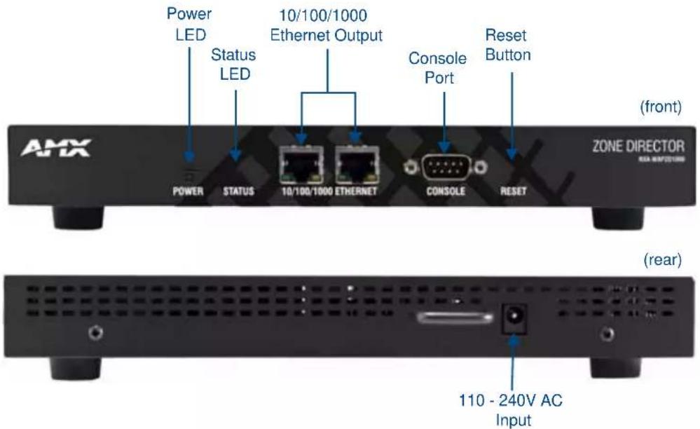
FIG. 1 NXA-WAPZD1000 ZoneDirector
Overview
The NXA-WAPZD1000 serves as a central control system for NXA-WAP1000 Smart Wireless Access Points (APs). The NXA-WAPZD1000 provides simplified configuration and updates, wireless LAN security control, RF management, and automatic coordination of Ethernet-connected and mesh-connected APs.
Using the NXA-WAPZD1000 in combination with NXA-WAP1000 APs allows deployment of a Smart Mesh network, to extend wireless coverage throughout a location without physically connecting each AP to Ethernet. In a SmartMesh network, the APs form a wireless mesh topology to route client traffic between any member of the mesh and the wired network. Meshing greatly reduces the cost and time requirements of deploying an enterprise-class WLAN, in addition to providing much greater flexibility in AP placement.
The NXA-WAPZD1000 also integrates network, radio frequency (RF), and location management within a single system. User authentication is accomplished with an integrated captive portal and internal database, or forwarded to existing Authentication, Authorization and Accounting (AAA) servers, such as RADIUS or Active Directory. Once users are authenticated, client traffic is not required to pass through the NXA-WAPZD1000, thereby eliminating bottlenecks when higher speed Wi-Fi technologies, such as 802.11n, are used.
In addition, the NXA-WAPZD1000 supports rogue AP detection and the ability to blacklist client devices from the network — all of which are easily configured and enabled system-wide. When multiple APs are in close proximity, the NXA-WAPZD1000 automatically controls the power and the channel settings on each AP to provide the best possible total coverage and resilience.
The NXA-WAPZD1000 also uses Browser-Based Configuration Pages to customize and manage all aspects of the device and the network from any PC or other Internet-enabled device with a Web browser.
Product Specifications
| NXA-WAPZD1000 Specifications | |
| Dimensions (HWD): 1 1/2" x 6 5/16" x 9 13/16" (39 mm x 159 mm x 250 mm) | |
| Weight: | 2.2 lbs (1 Kg) |
| Power Requirements: • Input: 110 - 240V AC• Output: 12V DC, 1A | |
| Front Panel Components: | |
| Power LED: Green LED: the device is receiving power. | |
| Status LED: • Steady green LED: Device is configured.• Blinking green LED: Device in factory default settings.• Steady amber LED: Device is shut down but still connected to a power source.• Flashing amber LED: Device is starting up or shutting down. | |
| 10/100/1000 Ethernet: Two 10/100/1000Mbps RJ-45 ports for Ethernet connectivity.• Solid green or amber left LED: The port is connected to a device.• Blinking green or amber left LED: The port is transmitting or receiving data traffic.• Green right LED: The port is connected to a 1000Mbps device.• Amber right LED: The port is connected to a 100Mbps or10Mbps device. | |
| Console port: DB-9 port for accessing the NXA-WAPZD1000 command line interface. | |
| Reset Button: Hold the reset button for 8 seconds to reset the device. | |
| Rear Panel Components: | |
| 110 - 240V AC Input: One 110-240 power jack. | |
| Operating Environment: • 32°F - 122°F (0°C - 50°C)• Operating humidity - 15% – 95% (non-condensing) | |
| Certifications: • FCC | • IC• CE• C - T i ck• VCCI• EN 60950-1• R o H S |
| Included Accessories: | • External power adapter (for more information, refer to the Power Adapter Compatibility section on page 11) |
| Other AMX Equipment: | • NXA-ENET8POE Gigabit PoE Ethernet Switch (FG2178-62)• NXA-WAP1000 Smart Wireless Access Point, US Operation (FG2255-51)• NXA-WAP1000 Smart Wireless Access Point, Operation Outside US (FG2255-53) |
Common Applications
The NXA-WAPZD1000 is ideal for homes and businesses that require a robust and secure WLAN that can be easily deployed, centrally managed and automatically tuned. The NXA-WAP1000 is perfect for environments where high bandwidth applications such as video streaming are accessed simultaneously from several wireless devices such as iPads, laptops, and gaming consoles.
Features
- Configure and Install in Minutes - Automatically discovers and configures AMX NXA-WAP1000 Wireless Access Points, making them instantly manageable
- Smart Wireless Mesh Networking - Simplifies deployment and reduces installation cost by eliminating the need to run Ethernet cable to every AMX NXA-WAP1000
- Automatically Adapts to Wi-Fi Signal Changes in Real-time - The SmartMesh Networking is self-organizing, self-optimizing, and self-healing to provide maximum performance and reliability
- Complete Centralized WLAN Control - Dynamically controls the RF channel assignment and transmit power level for each NXA-WAP1000 Wireless Access Point
- Integrated Wi-Fi Client Performance Tools - Ruckus SpeedFlex™ allows administrators to determine client Wi-Fi performance, either locally or remotely, over the wireless LAN to improve troubleshooting
- Secure Admission Control Across the WLAN - The NXA-WAP1000 centralizes authentication and authorization decisions for all access points
- Automatic User Security - Supports Ruckus's patent-pending Dynamic Pre-Shared Key (PSK) capability eliminating the requirement to configure and update individual PC client devices with unique encryption keys
Power Adapter Compatibility
The NXA-WAPZD1000 is shipped with an appropriate power adapter for the country in which it is to be used:
- FG2255-52: Includes US Power Adapter for use in US, Canada, Colombia, Ecuador, Mexico
- FG2255-54K: Includes EU Power Adapter for use in Europe (except UK), Chile, Egypt, Indonesia, Pakistan, Saudi Arabia (except Dharan), Vietnam
- FG2255-55K: Includes AU Power Adapter for use in Australia and New Zealand
- FG2255-56K: Includes China AU style CCC certified Power Adapter for use in China
● FG2255-57K: Includes India Power Adapter
● FG2255-58K: Includes Korea Power Adapter - FG2255-59K: Includes UK Power Adapter for use in the United Kingdom, Hong Kong, Malaysia, Singapore, and United Arab Emirates (UAE)
- FG2255-60K: Includes US Power Adapter with 110 and 220 power input for use in Brazil, Philippines, Saudi Arabia (Dharan), Taiwan, Thailand, Uruguay
Introduction
Installation and Setup
Introduction
Setting up a wireless network with the NXA-WAPZD1000 begins when you disperse a number of wireless access points (APs) for efficient coverage of your worksite. After you connect the APs to the NXA-WAPZD1000 (through network hubs or switches) and complete the “Zero-IT” setup, you have a secure wireless network for both registered users and guest users.

"Zero-IT" refers to the NXA-WAPZD1000's simple setup and ease-of-use features, which allow end users to easily configure wireless settings on Windows 7, Windows Vista, Windows XP, Mac OS X, iPhone and iTouch client devices.
After using the Browser-Based Configuration Pages (for more information, please refer to the Browser-Based Configuration Pages section on page 19) to set up user accounts for staff and other authorized users, your WLAN can be put to full use, enabling users to share files, print, check email, and more. And as a bonus, guest workers, contractors and visitors can be granted controlled access to your Ruckus WLAN with a minimum of setup.
You can now fine-tune and monitor your network through the Browser-Based Configuration Pages, which enables you to customize additional WLANs for authorized users, manage your users, monitor the network's security and performance, and expand your radio coverage, if needed.
Powering the NXA-WAPZD1000
To power up the NXA-WAPZD1000, connect the appropriate power adapter (for more information, please refer to the Power Adapter Compatibility section on page 11) to the power jack at the rear of the device and press the Power button to apply power. Check the LED in the Power button on the front of the device: if it is not lit, the device is NOT receiving power. If the power cable or adapter is connected to a power source, verify that the power cable is connected properly to the power jack.
To shut off the device, press and hold the Power button for one to two seconds, and the Status LED will switch from green to amber to denote that the device is shut down. Press the button again to restart the device.
Resetting the NXA-WAPZD1000
The NXA-WAPZD1000 may be reset in one of two modes. To reset the device while saving its current configuration, press the Reset button on the front of the device for one to two seconds.
To restore the device to its factory defaults, press and hold the Reset button for 8 seconds. The Status LED will now start flashing green to denote its default status.

Resetting the NXA-WAPZD1000 to its factory default settings will erase all previous configuration changes.
Configuring the NXA-WAPZD1000
In order to configure the NXA-WAPZD1000, you will need the following items or information:
- A Windows XP/Service Pack 2-equipped PC Sun Java Runtime Environment, v5 or later, installed on the administration PC
● A Web browser; either Internet Explorer (v6 or later) or Mozilla Firefox (v1.4 or later) - The IP address, netmask, gateway and DNS server addresses assigned to the NXA-WAPZD1000, if it is intended to have a static network address.

The NXA-WAPZD1000's default IP address is 192.168.0.2, with a network mask of 255.255.255.0. The NXA-WAPZD1000 is shipped with its default IP address settings as "DHCP", but if it is installed outside of a DHCP network, the device will revert to the default IP address.
To configure the NXA-WAPZD1000 and its companion NXA-WAP1000 devices:
- Download the NXA-WAPZD1000 firmware from www.amx.com and copy it to your PC's desktop.
- Connect the NXA-WAPZD1000 to a convenient power source and press the power button.
- After the Power LED is lit, the Status LED is a blinking red light.
- When the NXA-WAPZD1000 is powered up, the Status LED is a blinking green light, indicating that the system is in the "factory default" state. After you complete the Setup Wizard, the Status LED will be a steady green light.
Once the NXA-WAPXZD1000 is on and connected to your network, use your administration PC to "discover" it, verifying its connection. This automatically starts the Setup Wizard.
- Open the My Network Places window from your PC desktop.
- Click the Show icons for networked UPnP (Universal Plug and Play) devices link in the Network Tasks pane.
- If the Show UPnP Device Icons confirmation dialog box appears, click Yes to proceed. Windows sets up the feature, then activates it.
- After Windows checks the network, a new "NXA-WAPZD1000" icon appears in the My Network Places window. To proceed with setup, double-click that icon.
- The NXA-WAPZD1000 ZoneDirector Wireless Setup wizard appears, ready for wireless network configuration.
If you prefer not to use UPnP, you can type in the NXA-WAPZD1000's IP address into a Web browser. In case the LAN has no DHCP server, the NXA-WAPZD1000's default IP address is 192.168.0.2, with a network mask of 255.255.255.0. If a DHCP server is used, an IP address is assigned automatically.

After you complete the Setup Wizard, the Status LED will be a steady green light.
Working with the Setup Wizard
Before using the Wireless Setup wizard, obtain and enter the following information to complete the configuration:
- Language: Pick the language you prefer to use in the WebUI application from the drop-down list. (This is separate from OS/System or browser language settings.)
- General: Create a unique Name for the NXA-WAPZD1000. Use only letters and numbers for the name. Choose country code.
- Management IP: If you select DHCP, you must connect your NXA-WAPZD1000 to the local network via one of the Ethernet ports. The wizard will display the IP address it acquires from the local network. Write this down, as you will need it later. If you selected Manual, then enter the required network settings in the (now) active text fields.
- Wireless LANs: Enter the network name (ESSID). If you choose WPA-PSK for security, enter a secure Passphrase for your WLAN. (Make a note of the passphrase, as some users may need it when connecting their clients.)
- Guest WLAN (optional): click the check box to create a Guest WLAN in addition to the corporate WLAN, then enter the name of the Guest WLAN.
- Administrator: Set up both the “admin” account, and the first network user account (representing you as the administrator).

The user name and password can be any combination of letters and numbers, plus underscores or hyphens.

The Setup Wizard will only appear when connecting to an NXA-WAPZD1000 in the factory default mode. For more information on returning a device to the factory default mode, please refer to the Resetting the NXA-WAPZD1000 section on page 13.
- Review the wizard Confirmation entries. If you need to make a correction, click Back until the appropriate setup screen appears, then make the changes.
- When the wizard Finish screen appears, note the instructions, including the IP address now assigned to the NXA-WAPZD1000. These will enable you to log into the newly-configured NXA-WAPZD1000.
Connecting NXA-WAP1000s to your local area Ethernet network
To connect the NXA-WAP1000s to the local Ethernet network:
- Distribute the NXA-WAP1000s around your worksite, making sure they are 100 to 200 feet apart to ensure the best coverage.
- Record each WAP's Ethernet MAC address (printed on the bottom of every WAP), and note each devices' exact worksite location.
- Connect each NXA-WAP1000 to an Ethernet port. When the NXA-WAP1000s have powered up, they will automatically discover the NXA-WAPZD1000.
Accessing the NXA-WAPZD1000's Command Line Interface
Aside from using the NXD-WAPZD1000's Browser-Based Configuration Pages (page 19), you can also perform many management and configuration tasks using the NXD-WAPZD1000's Command Line Interface (CLI) by connecting directly to the Console port.
To access the NXD-WAPZD1000 CLI:
- Connect an admin PC to the NXD-WAPZD1000 Console port (FIG. 2), using a DB-9 serial cable.
- Launch a terminal program, such as Hyperterminal, PuTTY, etc. (FIG. 2)
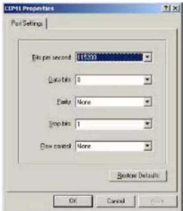
FIG. 2 Configuring a terminal client
-
Enter the following connection settings:
-
Bits per second: 115200
- Data bits: 8
- Parity: None
- Stop bits: 1
-
Flow control: None
-
Click OK or Open to connect (depending on your terminal client).
-
At the Please Login prompt, enter the admin login name (default: admin) and password (default: admin).
You are now logged into the NXA-WAPZD1000 with limited privileges. As a user with limited privileges, you can view a history of previously executed commands and ping a device. If you want to run more commands, you can switch to privileged mode by entering enable at the root prompt.
To view a list of commands that are available at the root level, enter help or ?
About Wireless WLAN Security
When you connect to the NXA-WAPZD1000 for the first time and run the Setup Wizard, you are prompted to set up two basic WLAN configurations -- an Internal WLAN for your internal users, and a Guest WLAN for guests. By default, authorized users connect to your internal WLAN, and visitors to your organization connect to the Guest WLAN. You can create additional WLANs and WLAN groups for more specific roles.
One of the first things you should do once your device is installed is decide on which methods of authentication and encryption to use for regular internal users and for guests.
Authentication options include:
- Open (no authentication)
● Shared (a single key shared among all users)
802.1X EAP - MAC Address
Encryption options depend on which type of authentication is chosen. Even with Open authentication, you can still encrypt WLAN traffic using WPA, WPA2 or WEP encryption. If you choose Shared authentication, you will only be able to use WEP encryption, because WPA and WPA2 use unique dynamically generated keys. WPA/WPA2 provides increased security, but limits flexibility because some client devices do not support the newer standards.
Certificate-based 802.1X EAP is a very secure authentication/encryption method that requires a backend authentication server such as RADIUS, Active Directory or other LDAP (Lightweight Directory Access Protocol) server. Your choice mostly depends on what kinds of authentication your users' client devices support.
One drawback to 802.1X is the more labor-intensive setup, which can require (among other tasks) the transfer of root certificate copies to your users, who must then import the certificates into their client devices. This task can be automated by using the Wireless Zero-IT Activation, which significantly reduces the amount of setup required.
Finally, you can choose to authenticate clients by MAC address. This can be used to allow or deny access to clients based on their MAC addresses. Of course, it also requires that each authorized client's MAC address be listed in an authentication database.
Enabling Smart Redundancy
The NXA-WAPZD1000's Smart Redundancy feature allows two devices to be configured as a redundant pair, with one unit actively managing your network while the other serves as a backup in standby mode, ready to take over if the first device fails or loses power.
Each NXA-WAPZD1000 will either be in active or standby state. If the active device fails, the standby device becomes active. When the original active device recovers, it automatically assumes the standby state as it discovers an already active device on the network.
The NXA-WAPZD1000 in active state manages all APs and client connections. The device in standby state is responsible for monitoring the health of the active unit and periodically synchronizing its settings to match those of the active device. The device in standby state will not respond to Discovery requests from APs and changing from active to standby state will release all associated APs.
When failover occurs, all associated APs will continue to provide wireless service to clients during the transition, and will associate to the newly active NXA-WAPZD1000 within approximately one minute.
Configuring the NXA-WAPZD1000 for Smart Redundancy
For management convenience, both NXA-WAPZD1000s in a Smart Redundancy deployment can be managed via a single shared IP address. In this situation, three IP addresses would need to be configured:
- Primary device's real address
- Backup device's real address
- Management address
All configuration changes are made to the active NXA-WAPZD1000 and synchronized to the standby unit. The user can access the Browser-Based Configuration Pages from any of the three IP addresses, however not all configuration options are available from the standby device.
To enable Smart Redundancy:
- Log in to the Browser-Based Configuration Pages (page 19), using the IP address of the NXA-WAPZD1000 you will initially designate as the primary unit.
- Go to Configure > System, and set a static IP address under Device IP Settings, if not already configured.
- Click Apply. You will need to log in again using the new IP address (if changed).
- On the same page, locate the Smart Redundancy section and enable the check box next to Enable Smart Redundancy.
- Enter the IP address of the backup unit under Peer IP Address (if known). If you have configured Limited ZD Discovery under Configure > Access Points > Access Point Policies, you must identify the IP address of both devices that the APs should connect to when Smart Redundancy is active. If the Limited ZD Discovery and Smart Redundancy information you enter is inconsistent, a warning message will be displayed asking you to confirm. Note that using the Smart Redundancy feature instead of the Limited ZD Discovery feature whenever possible is highly recommended.
- Enter a Shared Secret for two-way communication between the two devices (up to 15 alphanumeric characters).
- Click Apply to save your changes and prompt the NXA-WAPZD1000 to attempt to discover its peer on the network.
- If discovery is successful, the details of the peer device will be displayed to the right. If discovery is unsuccessful, you will be prompted to retry discovery or continue configuring the current device.
- Install the second NXA-WAPZD1000 and complete the Setup Wizard.
- Go to Configure > System, enable Smart Redundancy and enter the primary NXA-WAPZD1000's IP address in Peer IP address.
- Click Apply. If an active NXA-WAPZD1000 is discovered, the second device will assume the standby state. If an active device is not discovered, you will be prompted to retry discovery or to continue configuring the current device.
Once Smart Redundancy has been enabled, a status link is displayed at the top of the Dashboard (page 20).

If you have two NXA-WAPZD1000s of the same license level, using the Smart Redundancy feature is recommended. If you have two NXA-WAPZD1000s of different models or different license levels, you can use Limited ZD Discovery to provide limited redundancy. However, this method does not provide synchronization of the user database.

If you disable Smart Redundancy after it has been enabled, both NXA-WAPZD1000s will revert to active state, which could result in unpredictable network topologies. Therefore, factory resetting the standby device before disabling Smart Redundancy is recommended.
Forcing Failover to the Backup NXA-WAPZD1000
After Smart Redundancy has been enabled, you can view the status of both the primary and backup units from the Dashboard by dragging the Smart Redundancy widget (page 21) onto the workspace.
The Failover button can be used to force a role reversal to make the standby device the active unit. This widget also displays the state (active, standby or disconnected) of both devices, as well as their IP addresses and the Management IP address, if configured.
Browser-Based Configuration Pages
Overview
The NXA-WAPZD1000 utilizes configuration pages accessible through any Web browser. The configuration page interface is divided into six components that you can use to manage and monitor your entire WLAN, including the NXA-WAPZD1000 and all access points connecting to it.
To access the browser-based configuration pages, enter the IP address for the NXA-WAPZD1000 into your preferred Web browser. The browser will then display the Ruckus Wireless ZoneDirector Login page (FIG. 3).
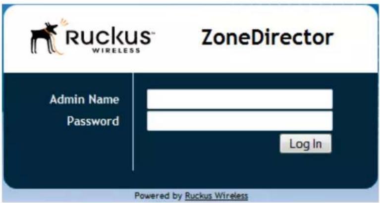
FIG. 3 NXA-WAPZD1000 ZoneDirector login page

The default Admin Name is admin, and the default Password is admin. These may be changed at any time from the Preferences page under the Administer tab (page 112).
Dashboard
The Dashboard (FIG. 4) offers a number of self-contained indicators and tables that summarize the network and its current status. Some indicators have fields that link to more focused, detailed views on elements of the network.
![Ruckus ZoneDirector Dashboard Monitor Configure Administer System Overview System Name: Pv_Ruckus_Controller IP Address: 190.168.218.33 MAC Address: 00125/C430/72.4E Update: In $mn Model: 22/006 Licensed APs: 9 S/N: CH000001938 Version: 9.0.0.0 build HR Devices Overview of APs: 1 of Client Devices: 2 of Rogue Devices: 7 Usage Summary 1 hr 24 hr Max Concurrent Users: 3 2 Bytes Transmitted: 2436 21mn Average Signal d85 42 45 of Rogue Devices: 7 18 Currently Active WLANs Names/ESSIDs WAP1000_5G WAP1000_2G PV1_2G PV2_2G PV3_2G PV1_3G PV2_3G PV3_3G QuickBrownFoxJumpsOverTheLacyDog Search terms: Include at terms Include any of these terms Currently Active WLAN Groups Name Description WLANS Default Default WLANs for Access Points PV2_5G, PV3_5G 2G_Oluy WAP1000_2G 5G_Oluy WAP1000_5G Multiage SSDs 2G PV2_2G, PV3_2G, QuickBrownFoxJumpsOverTheLacyDog Multiage SSDs 5G PV2_5G, PV3_5G Search terms: Include at terms Include any of these terms Most Recent User Activities Date/Time Severity: User Activities 2011/01/01 13:42:34 Low Pusion 1 User[PUser] joins WLA@PV2_5G from AP[ac67.06.37.02.03] 2011/01/01 13:41:54 Low Pusion 1 User[PUser] joins WLA@PV3_2G from AP[ac67.06.37.02.03] 2011/01/01 13:40:43 Low Pusion 1 User[PUser] disconnects from WLA@PV3_5G at AP[ac67.06.37.02.03] 2011/01/01 13:40:43 Low Pusion 1 User[PUser] disconnects from WLA@PV2_2G at AP[ac67.06.37.02.03] 2011/01/01 13:31:41 Low Pusion 1 User[PUser] joins WLA@PV3_5G from AP[ac67.06.37.02.03] Most Recent System Activities Date/Time Severity: Activities 2011/01/01 13:40:23 Low AP[ac67.06.37.02.03] state set to [Spot AP] on channel [36 (11a in)] with download (enabled) 2011/01/01 13:41:28 Low WLA@PV4_5G has been deployed on radio [11a in] of AP[ac67.06.37.02.03] with BSA[ac67.06.37.02.03] 2011/01/01 13:41:28 Low WLA@PV3_5G has been deployed on radio [11a in] of AP[ac67.06.37.02.03] with BSA[ac67.06.37.02.03] 2011/01/01 13:41:28 Low WLA@PV3_5G has been deployed on radio [11a in] of AP[ac67.Use not to [Spot AP] on channel [36 (11a in)] with download (enabled) WLA@PV4_5G has been deployed on radio [11a in] of AP[ac67.06.37.02.03] with BSA[ac67.06.37.02.03] WLA@PV3_5G has been deployed on radio [11a in] of AP[ac67.06.37.02.03] with BSA[ac67.Use not to to [Spot AP] on channel [36 (11a in)] with download (enabled)](/content/2026/05/897082/images/38439a0348b998d4a17a622e04f8d28d219e96900592d896570cf9a73a1ccebf.jpg)
FIG. 4 ZoneDirector Dashboard with default indicators
The Dashboard indicators may be moved, refreshed, or hidden as needed. To move an indicator, click and drag the title across the Dashboard and release it on the desired location. Update the information in the indicator by clicking the Refresh icon on the right side of the indicator, and hide the indicator in the Add Widgets column by clicking the Hide icon on the right side.
| Default Dashboard Indicators | |
| System Overview: Shows NXA-WAPZD1000 system information, including its IP address, MAC address, model number, maximum number of licensed APs, serial number, and software version number. | |
| Devices Overview: Shows the number of access points being managed by the NXA-WAPZD1000, as well as the number of clients connected to these managed APs. It also shows the number of rogue devices that have been detected by the NXA-WAPZD1000. | |
| Most Frequently Used Access Points: | Lists the access points that are serving the most client requests. |
| Usage Summary: Shows usage statistics for the last hour and the last 24 hours. | |
| Most Active Client Devices: | Identifies the most active clients by MAC address, IP address, and user name. Bandwidth usage is calculated in megabytes (MB) and is based on the total number of bytes sent (Tx) and received (Rx) by each client from the time it associated with the managed access point. |
| Currently Active WLANs: Shows details of currently active NXA-WAPZD1000 WLANs. | |
| Currently Active WLAN Groups: | Shows details of available WLAN groups. If you have not created any WLAN groups, only the Default WLAN group appears. |
| Most Recent System Activities: Shows system activities related to NXA-WAPZD1000 operation. | |

Some indicators may not be present upon initial view. The Add Widgets feature, located at the bottom left area of the screen, enables you to show or hide indicators.
Dashboard Widgets
Widgets are Dashboard components, each containing a separate indicator or table as part of the active Dashboard. Each widget may be added or removed to enhance your NXA-WAPZD1000 summary needs. All unused widgets remain hidden until you click the Add Widgets link at the bottom of the Dashboard.
To add a widget to the Dashboard, click and drag the widget into the main Dashboard. An outline appears that shows its potential position on the page. Release the widget at its desired position, and the widget will display its available information. To remove a widget from the Dashboard, click the red Hide button at the right of the component entry, and the widget will then appear in the Dashboard Widgets column.
![Dashboard Widgets Current Active WLARs Name:012006 Default: Default: WLSes for access terms: P12_30, P13_30 WS Help WS_Drop Multiple 0120_21 Multiple 0120_01 Search terms Include all terms Include any of these terms Current Active WLAR Groups Name Description WLARs Default Default: WLSes for access terms: P12_30, P13_30 WS Help WS_Drop Multiple 0120_21 Multiple 0120_01 Search terms Include all terms Include any of these terms Most Recent User Activities Date/Time Severity View Activities 2011-01-04 11:30:47 Low Project: 1 search[User] (pass WLS@P12_30) from @WLS@P12.01.03) 2011-01-04 11:30:57 Low Project: 1 search[User] (pass WLS@P12_30) from @WLS@P12.01.03) 2011-01-04 11:30:57 Low Area: 1 search[User] (connects from WLS@P12_30) from @WLS@P12.01.03) 2011-01-04 11:30:58 Low Project: 1 search[User] (connects from WLS@P12_30) from @WLS@P12.01.03) 2011-01-04 11:30:58 Low Project: 1 search[User] (connects from WLS@P12_30) from @WLS@P12.01.03) Most Recent System Activities Date/Time Severity Activities 2011-01-04 14:08:57 Low Administrator releases an active user from all APs 2011-01-04 12:36:58 High A new software(8) (to 74 to 52) with 888(497) is approved 2011-01-04 11:29:48 Low @WLS@P12.01.03 share set to [Read @F] on channel(8) (to 74 to 52) with download password 2011-01-04 11:29:48 Low VLS@P12_30 has been deployed or rated [To red] if @WLS@P12.01.03 with 888(497) on the date of VLS@P12.01.03 2011-01-04 11:29:49 Low VLS@P12_30 has been deployed or rated [To red] if @WLS@P12.01.03 with 888(497) on the date of VLS@P12.01.03] Print](/content/2026/05/897082/images/73f2dab63eef405d610a2269ab1a6a3fa163a229a27e319a1c4b848df0871300.jpg)
FIG. 5 Dashboard Widgets
The default reserve Dashboard Widgets include:
- Support: listing the basic contact information for Ruckus Wireless, including a link to the Registration page of the Administer Tab (for more information, please refer to the Product Registration section on page 122).
- Smart Redundancy: listing whether Smart Redundancy is enabled on the NXA-WAPZD1000. By default, Smart Redundancy is disabled: for more information on Smart Redundancy, please refer to the System section on page 44.
- Currently Managed APs: displaying all of the available WAPs being managed through the NXA-WAPZD1000, including the MAC address, the device name, the device description, the WAP model, its current status, the mesh mode being used, the device's IP address, its VLAN channel, and the number of clients currently accessing it. The component also allows the user to access the WAP's system information and RF information, as well as configure it for the network (for more information, please refer to the Access Points section on page 66), viewing its mesh topology, testing its wireless performance, troubleshooting its network connectivity (for more information, please refer to the Network Connectivity section on page 123), and restart the WAP.
● AP Activities: displaying the latest activities from individual WAPs on the network. - Mesh Topology: displaying the current mesh network of devices connected to the NXA-WAPZD1000, including the WAP, its signal (in dB), the access point description,
- Most Recent User Activities: displaying the latest actions made by the user with the NXA-WAPZD1000, including the date and time of the action, the action's severity, the user making the action, and the action itself.
In addition, choosing to hide any Dashboard component puts the component in the Widgets section as a selectable entry. These may be accessed and used at any time.
When finished installing or moving widgets, click the Finish link at the bottom of the Widgets section to save your changes. The Widgets column will disappear, but it accessible again by clicking the Add Widgets link again.
Monitor Tab
Reviewing Recent Network Events
You have two options for reviewing events in your network: [1] open a complete list of all events, or [2] look at specific lists of events in each Monitor tab workspace, such as the WLANs workspace “Events/Activities” table.
- Open the NXA-WAPZD1000 Dashboard (page 20) and look at the Most Recent User Activities table and Most Recent System Activities table for summaries of activity in the network.
- Go to the Monitor tab.
- Click any of the specific options, such as WLANs, Access Points, or Currently Active Clients.
- Look for an All Events table that specifically focuses on the selected WLAN category.
- Under the Monitor tab, click either the All Alarms button or the All Events/Activities button to see a complete list, with all categories represented in chronological order.
Monitoring Access Point Status
The NXA-WAPZD1000 provides several different features for monitoring the status and performance of your APs. The following are three ways you can quickly locate information on the APs that the device is managing:
- Open the Dashboard (page 20) for a snapshot of the most active APs. Click the MAC address link of any AP record to see more details.
- Go to Monitor >Map View (page 27) and click a radio frequency to see a heat-map rendering of the current RF coverage.
- Go to Monitor > Access Points (page 24) and review the usage and coverage of your APs. Click the MAC address link of any listed APs to see more details.
Access Points
The Access Points page provides an overview of currently managed APs and consists of two tables: Currently Managed APs and Events/Activities. Both sections list the first 15 entries by default and can be expanded using the Show More button. Click on the MAC address, device name or user name for more detailed information on the specific AP or client.
![Access Points This table lists all currently active access points, and highlights basic details, such as number of clients per AP, below is an AP-specific table of events and activities. Currently Managed APs MAC Address Device Name Description Model Status Mesh Mode IP Address VLAM Channel Clients Action ac#174063702@ch RuchusAP cTT363 Connected (Host AP) Auto FIS.168.219.155 26 (11a1n-40), 1 (11gln-20) 2 Search terms Include at terms Include any of these terms Events/Activities Data/Time Severity User Accounts 2011/01/04 12:16:08 High A new Rogue(2012csh745c152) with (003)(M4A752) is detected 2011/01/04 11:26:40 Low Player3 User(Provider) Joint WLAPIV2_352 from AP[ac#7.06.37.02.c0] 2011/01/04 11:35:37 Low Player3 User(Provider) Joint WLAPIV2_352 from AP[ac#7.06.37.02.c0] 2011/01/04 11:35:31 Low area User[center] disconnects from WLAPIV2_352 at AP[ac#7.06.37.02.c0] 2011/01/04 11:35:38 Low Player3 User(Provider) disconnects from WLAPIV2_352 at AP[ac#7.06.37.02.c0] 2011/01/04 11:35:36 Low Player3 User(Provider) Joint WLAPIV2_352 from AP[ac#7.06.37.02.c0] 2011/01/04 11:35:19 Low area User[center] disconnects from WLAPIV2_352 at AP[ac#7.06.37.02.c0] 2011/01/04 11:34:40 Low Player3 User(Provider) disconnects from WLAPIV2_352 at AP[ac#7.06.37.02.c0] 2011/01/04 11:37:54 Low Player3 User(Provider) Joint WLAPIV2_352 from AP[ac#7.06.37.02.c0] 2011/01/04 11:35:48 Low AP[ac#7.06.37.02.c0] stake set to [Host AP] on channels [R (11a1n)] with downtime [modified] 2011/01/04 11:35:32 Low Player3 User(Provider) Joint WLAPIV2_352 from AP[ac#7.06.37.02.c0] 2011/01/04 11:35:36 Low area User[center] disconnects from WLAPIV2_352 at AP[ac#7.06.37.02.c0] 2011/01/04 11:35:39 Low Player3 User(Provider) Joint WLAPIV2_352 from AP[ac#7.06.37.02.c0] 2011/01/04 11:35:48 Low WLAPIV2_352 has been deployed on radio [1(a)in] of AP[ac#7.06.37.02.c0] with BOSID[ac#7.06.37.02.c0] 2011/01/04 11:35:48 Low WLAPIV2_352 has been deployed on radio [1(a)in] of AP[ac#7.06.37.02.c0] with BOSID[ac#7.06.37.02.c0] search terms Include at terms Include any of these terms Show More C ( > 15 +475)](/content/2026/05/897082/images/b65c25caeab3fdf6df3f92e5f7c542128b191d1d6c46913d41640911eac08959.jpg)
FIG. 6 Monitor Tab - Access Points
| Monitor Tab - Access Points | |
| Currently Managed APs: | |
| MAC Address: The AP's MAC address. Click this link to view details specific to this AP. | |
| Device Name: The AP's "name." This can be modified on the Configure >AccessPoints page by clicking the Edit link next to the AP's MAC address. | |
| Description: | The AP's "description." This can be modified on the Configure >AccessPoints page by clicking the Edit link next to the AP's MAC address. |
| Model: The model number, if applicable. | |
| Status: Displays the current status of the AP from the NXA-WAPZD1000's perspective:Approval PendingConnectedDisconnectedRoot APMesh APe Mesh APNumber of hops | |
| Mesh Mode: Displays whether the AP is manually set as a Root or Mesh AP, or set to automatically choose Mesh mode. | |
| IP Address: The IP address of the AP. | |
| VLAN The VLAN ID, if VLAN is enabled. | |
| Channel: Displays the channel number and channel width. On dual band APs, details for each radio are shown. | |
| Clients: The number of clients currently connected to this AP. | |
| Action: These icons allow you to configure and troubleshoot APs individually | |
| Events/Activities: | |
| Date/Time: The date and time of the event. | |
| Severity: | The severity of the event. |
| User: | The name of the AP user, if applicable. |
Monitor Tab - Access Points (Cont.)
Activities: The specific activity involved in the event.
Assessing Current Performance Using the Access Point Table
To assess the current performance of currently monitored Access Points:
- Go to Monitor > Access Points.
- Review the Currently Active APs for specific AP settings, especially the Channel and Clients columns.
Monitoring Individual APs
When you click on the MAC address of any AP, the Access Points page changes to a detailed view of information related to that AP.
The Monitor > Access Points > [MAC Address] page provides the following details on the specific AP:
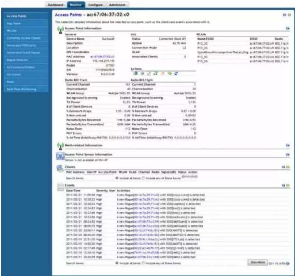
FIG. 7 Monitor Tab - Access Points - [MAC Address] page
| Monitor Tab - Access Points - [MAC Address] | |
| General: Displays general information on the AP, including software version, IP address and model number. | |
| Info: Displays uptime, clients and mesh status. | |
| Actions: Action icons provide tools for managing the AP. | |
| WLANs: Displays the WLANs that this AP is supporting. | |
| Radio 802.11(a/n or g/n): Displays details on the 2.4GHz (g/n) and 5GHz (a/n) radios. | |
| Monitor Tab - Access Points - [MAC Address] (Cont.) | |
| Neighbor APs: Displays nearby APs, their channel and signal strength. | |
| Sensor Information: Displays AP orientation and temperature details as reported by the AP's internal sensors (not supported on all APs). | |
| Clients: Displays a list of the currently connected clients. Action icons can be used to configure or troubleshoot a client from this list. | |
| Events: Displays an AP-related subset of the All Events / Activities table. |
Neighbor APs
The NXA-WAPZD1000 uses several calculations to determine which APs are in proximity to one another. This information can be useful in planning or redesigning your Smart Mesh topology or in troubleshooting link performance issues.
Details on neighbor APs include:
- Access Point: The AP's description, if configured, or the MAC address if no name or description is available.
- Channel: The channel that the neighbor AP is currently using.
• Signal (dB): Signal strength. - Path Score (status): A higher score indicates better performance over the link between this AP and its neighbor. Note that only APs of the same model or radio type can mesh with one another. If the AP is of a different model than the one you are currently viewing, this field will display N/A (Unknown).
Restarting an Access Point
One helpful fix for network coverage issues is to restart individual APs. To do so:
- Go to Monitor > Access Points.
- When the Access Points page appears, look in the Currently Managed APs table for the particular Access Point record. The Status column should display "Connected."
- Click the Restart icon. The Status column now displays "Disconnected" along with the date and time when the NXA-WAPZD1000 last communicated with the AP.
After restart is complete and the NXA-WAPZD1000 detects the active AP, the status will be returned to "Connected."
Map View
This page provides a fast scan of key network factors: APs (legitimate, neighboring and rogue), client devices, and radio frequency (RF) coverage. You can see what devices are where in your floorplan, and visually evaluate network coverage.
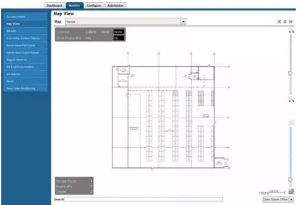
FIG. 8 Monitor Tab - Map View
| Monitor - Map View | |
| Map: Select the floorplan to view from the Map drop-down list. | |
| Coverage: | Selecting 2.4GHz enables a signal strength view of your placed 2.4GHz APs. Selecting 5GHz displays the signal coverage of 5GHz radios.Selecting either 2.4 or 5GHz opens the Signal (%) legend on the right side of the Map View. |
| Show Rogue APs: | Selecting Yes displays any detected rogue APs in the floorplan. |
| Access Points: The number of active APs within the selected map. | |
| Rogue APs: The number of rogue APs within the selected map. | |
| Clients: All associated clients within the selected map. | |
| Search: Enter a string, such as part of an AP's name or MAC address, and themap is filtered to show only the matching results. Clearing the search value returns the map to its unfiltered view. | |
| Signal: This colored legend displays the signal strength coverage when youselected either 2.4GHz or 5GHz for Coverage | |
Image Requirements
- A floorplan image in .GIF, .JPG or .PNG format.
● The image should be monochrome or grayscale.
● The file size should be no larger than 200KB in size. - The floorplan image should be (ideally) no larger than 10 inches (720 pixels) per side.
Placing the Access Point Markers
After using the Configure > Maps options to import your floorplan image (for more information, please refer to the Maps section on page 77), you can use the Monitor tab's Map View to distribute markers that represent the APs to the correct locations. This will give you a powerful monitoring tool.

If you have imported multiple floor plans representing multiple floors in your building(s), make sure you place the access point markers on the correct floorplan.
- Have the list of APs handy, with MAC addresses and locations.
- Go to Monitor >Map View (if it is not already in view).
- Look in the upper left corner for AP marker icons. There should be one for each AP, with a tiny red question mark at the top.
- Look at the MAC address notation, under the marker icon, to identify a marker.
- Drag each marker icon from the upper left corner into its correct location on the floorplan.
When you finish, you can make immediate use of the Map View to optimize your wireless coverage, as detailed in the Tagging Management Traffic to a VLAN section on page 67.
Using the Map View Tools
If your worksite floorplan has been scanned in and mapped with APs, the Map View will display a graphical image of your physical network AP distribution.
A number of helpful features are built into the Map View:
- Unplaced APs area: As noted in Importing a Map View Floorplan Image, when you first open the Map View, newly placed APs appear in this area. If they are approved for use (see the Connecting the APs to the WLAN section on page 69), you can drag them into the correct location in the floorplan. Unplaced APs are available across all of the floor plans you upload. Thus, you can toggle between maps and place each AP on the appropriate map.
- Floorplan area: The floorplan displays in this main area. You can manipulate the size and angle of the floorplan by using the tools on this screen.
- Upper slider: The upper slider is a zoom slider, allowing you to zoom in and out of the floorplan. This is helpful in exact AP marker placement, and in assessing whether physical obstructions that affect RF coverage are in place.
- Lower slider: The bottom slider is the image contrast slider, allowing you to dim or enhance the presence of the floorplan. If you have trouble seeing the floorplan, move the slider until you achieve a satisfactory balance between markers and floorplan details.
- Scale legend: To properly assess the distances in a floorplan, a scaler has been provided so that you can place APs in the most precise location. The scale works best when the floorplan view has not been zoomed in or out. The scale offers both feet and meters as units of measure. Use a physical object as a reference to the scale in order to judge distances on your floorplan. For example, cut a piece of paper to the length of the scale, and then use that piece of paper on the floorplan to measure off distance increments.
- Open Space Office drop-down list: Open Office Space refers to the methodology used to compute RF coverage/signal% (i.e., heat map) based on the current environment.
| Map View Icons | |
| Click this icon, and then click an AP from the floorplan to remove that AP. | |
| Click this icon to rotate the floorplan. When clicked, rotation crosshairs appear in the center of the map; click and hold these crosshairs and move your cursor to rotate the view. | |
| Refresh the floorplan. | |
AP Icons
Each AP marker has variable features that help indicate identity and status:
| AP Icons | |
| A normal AP marker displays the model number and description of the AP. It also shows the number of users that are currently associated with the AP. | |
| An unplaced AP marker displays a question mark above the icon. | |
| A rogue AP displays a smaller red icon imprinted with a “bug.” | |
| In a Smart Mesh network, an isolated AP displays a red “X” above the icon. | |
| When Smart Mesh is enabled, a circled number appears next to the AP icon to indicate that it is a Mesh AP. The number indicates the number of hops from this Mesh AP to the Root AP. | |
| When Smart Mesh is enabled, a blue square with an arrow indicates that it is a Root AP with active downlinks. Dotted lines that connect this AP to other APs indicate the active downlinks. | |
| When Smart Mesh is enabled, a gray square (dimmed) with an arrow indicates that it is a Root AP without any active downlinks. | |
| An AP with a red square with an arrow indicates this is an eMAP. An eMAP uses its wired Ethernet interface as its uplink, and can mesh with other Mesh APs through its wireless interface. | |
Optimizing Access Point Performance Using the Map View
The NXA-WAPZD1000, through its Browser-Based Configuration Pages, enables you to remotely monitor and adjust key hardware settings on each of your network APs. After assessing AP performance in the context of network performance, you can reset channels and adjust transmission power, or adjust the priority of certain WLANs over others, as needed.
Assessing Current Performance Using the Map View
To assess current AP performance using Map View:
- Go to Monitor > Map View.
- If Map View displays a floorplan with active device symbols, you can assess the performance of individual APs, in terms of coverage.
- In the Coverage options, select 2.4GHz or 5GHz to view coverage for the radio band.
- When the "heat map" appears, look for the Signal (%) scale in the upper right corner of the map.
- Note the overall color range, especially colors that indicate low coverage.
- Look at the floorplan and evaluate the current coverage. You can make adjustments as detailed in the following procedure.
Improving AP RF Coverage
To improve AP RF coverage:
-
Click and drag individual AP markers to new positions on the Map View floorplan until your RF coverage coloration is optimized. Additional APs may be needed to fill in large coverage gaps.
-
When your adjustments are complete, note the new locations of relocated AP markers.
-
After physically relocating the actual APs according to the Map View placements, reconnect the APs to a power source.
-
To refresh the NXA-WAPZD1000 Map View, run a full-system RF Scan.
- When the RF scan is complete and the NXA-WAPZD1000 has recalibrated the Map View, you can assess your changes, and make further adjustments as needed.
Evaluating and Optimizing Network Coverage
If there are gaps or dead spots in your worksite WLAN coverage, you can use the NXA-WAPZD1000 to assess network RF coverage and then reposition APs to enhance coverage.
To assess network RF coverage:
- Go to Monitor > Map View.
- If Map View displays a floorplan with active device symbols, you can assess the performance of individual APs, in terms of coverage.
- For the Coverage option, click 2.4GHz or 5GHz.
- When the "heat map" appears, look for a Signal% scale in the upper right corner of the map. Note the color range, especially colors that indicate low coverage.
- Look at the floorplan and evaluate the current coverage.
Moving the APs into More Efficient Positions
To move the APs into more efficient positions:
- From Monitor > Map View, click and drag individual AP markers on the Map View floorplan until your RF coverage coloration is optimized. (You may need to acquire additional APs to fill in large coverage gaps.)
- To turn off the heat map and restore the floorplan to view, click None in the Coverage options.
- Note the new physical locations of relocated AP markers.
- After physically relocating the actual APs in accordance with Map View repositioning, disconnect and reconnect each AP to a power source.
When the NXA-WAPZD1000 has recalibrated the Map View after each AP restart, you can assess your changes, and make further adjustments as needed.
WLANs
The tables on the WLANs page currently active WLANs, currently active WLAN Groups, and an up-to-date record of WLAN events/activities.
![WLANs These tables list [1] currently active WLANs, [2] currently active WLAN Groups, and [3] are up-to-date record of WLAN events/activities. Click on a WLAN-name link, WLAN Group-name link or wAC address link for more details. Currently Active WLANs Name/ESIDs WAP1000_50 WAP1000_50 P1/1_50 P1/2_50 P1/3_50 P1/4_50 P1/5_50 QuickBrownFocusJumpsOverTheLacyDog Search terms Include at terms Include any of these terms (3:1-9:5):G Currently Active WLAN Groups Name Description WLANs Default Default WLANs for Access Points P1/2_50, P1/3_50 20_Day WAP1000_20 N0_Day WAP1000_50 Multiple 0000s 20 P1/2_50, P1/2_50; QuickBrownFocusJumpsOverTheLacyDog Multiple 000s 50 P1/2_50, P1/2_50 Search terms Include at terms Include any of these terms (3:1-9:5):G Events/Activities Date/Time Severity User Activities 2011/01/03 13:42:34 Low Participant User[Prisoner] joins VLAN(PV1_50) from AP(ac67/06:37/02:cc)] 2011/01/03 13:41:54 Low Participant User[Prisoner] joins VLAN(PV1_50) from AP(ac67/06:37/02:cc)] 2011/01/03 13:41:35 Low VLAN(PV1_50) has been deployed on radio [11g/s] of AP(ac67/06:37/02:cc)] with BSSO(ac67/06:37/02:cc)] 2011/01/03 13:41:35 Low VLAN(PV1_50) has been deployed on radio [11g/s] of AP(ac67/06:37/02:cc)] with BSSO(ac67/06:37/02:cc)] 2011/01/04 13:41:35 Low VLAN(QuickBrownFocusJumpsOverTheLacyDog) has been deployed on radio [11g/s] of AP(ac67/06:37/02:cc)] with BSSO(ac67/06:37/02:cc)] 2011/01/03 13:41:35 Low VLAN(PV1_50) has been deployed on radio [11g/s] of AP(ac67/06:37/CC) with BSSO(ac67/06:37/CC)# 2011/01/03 13:40:43 Low Participant User[Prisoner] connects from VLAN(PV1_50) at AP(ac67/06:37/CC)# 2011/01/03 13:40:43 Low Participant User[Prisoner] connects from VLAN(PV1_50) at AP(ac67/06:37/CC)# 2011/01/03 13:31:41 Low Participant User[Prisoner] joins VLAN(PV1_50) from AP(ac67/06:37/CC)# 2011/01/03 13:31:38 Low Participant User[Prisoner] connects from VLAN(PV1_50) at AP(ac67/06:37/CC)# 2011/01/03 13:31:29 Low Participant User[Prisoner] joins VLAN(PV1_50) from AP(ac67/06:37/CC)# 2011/01/03 13:30:91 Low Participant User[Prisoner] connects from VLAN(PV1_50) at AP(ac67/06:37/CC)# 2011/01/03 13:30:99 Low Participant User[Prisoner] joins VLAN(PV1_50) from AP(ac67/06:37/CC)# 2011/01/03 13:17:48 Low Participant User[Prisoner] connects from VLAN(PV1_50) at AP(ac67/06:37/CC)# Search terms Include at terms Include any of these terms Show More (3:1-9:5):G](/content/2026/05/897082/images/3caf10ddc8779184965066f7480dacb9060f6ad021c92beaa9e7105b1fdd8ace.jpg)
FIG. 9 Monitor Tab - WLANs
| Monitor Tab - WLANs | |
| Currently Active WLANs: | This is a listing of the currently active WLANs being managed by the NXA-WAPZD1000. |
| Names/ESSIDs: The name or ESSID of the individual WLAN. | |
| Authentication: The authentication mode being used by the WLAN. | |
| Encryption: The encryption mode being used by the WLAN. | |
| Clients: The number of clients accessed by the WLAN. | |
| Currently Active WLAN Groups: | This is a listing of the currently active groups of WLANs being managed by the NXA-WAPZD1000. |
| Name: The name used for the WLAN group. | |
| Description: (Optional) A more detailed description of the WLAN group. | |
| WLANs: The WLANs included within the group. | |
| Events/Activities: This is a breakdown of all activities engaged through WLANs managed by the NXA-WAPZD1000. | |
| Date/Time: The date and time of the logged event. | |
| Severity: The determined alert level for the event. | |
| User: The WLAN producing the event. | |
| Activities: The specific activity being logged. | |
| Show More: | Click this button to show 15 more previous events. |
Viewing a List of APs That Belong to a WLAN Group
To view the APs that belong to a particular WLAN group:
- Go to Monitor > WLANs.
- Under Currently Active WLAN Groups, click the WLAN group name for which you want to view the member AP list.
- On the page that loads, look for the Member APs section. All APs that belong to this WLAN group are listed.
Currently Active Clients
This page lists all currently connected client devices. Only those devices with a status of “authorized” are permitted access to the network
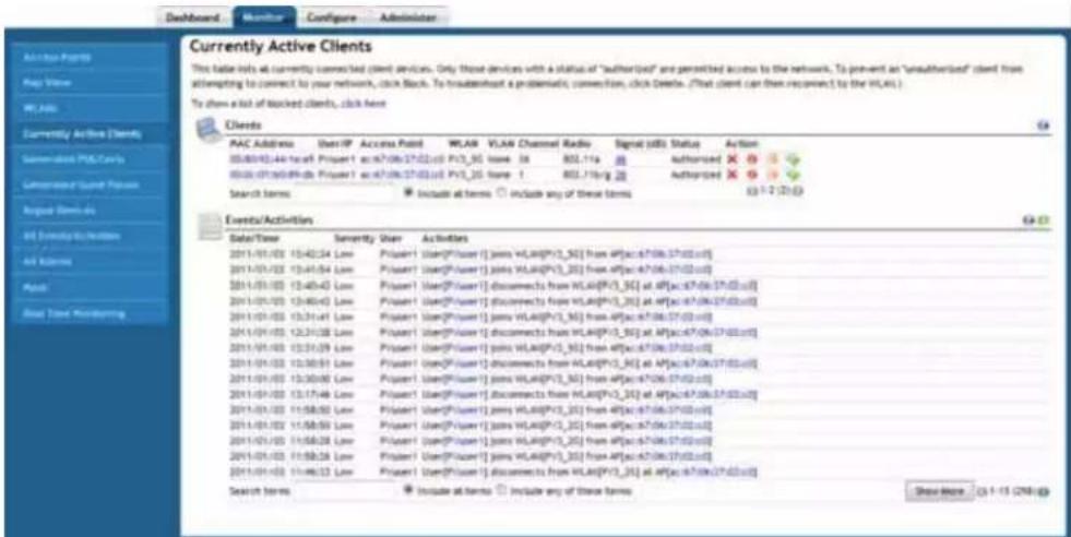
FIG. 10 Monitor Tab - Currently Active Clients
| Monitor Tab - Currently Active Clients | |
| Clients: This list catalogues all clients accessing a WLAN via the NXA-WAPZD1000. | |
| MAC Address: The MAC address of the client. | |
| User/IP: The name or IP address of the client. | |
| Access Point: The access point through which the client is connected to the network. | |
| WLAN: The WLAN through which the client is connected. | |
| VLAN: The VLAN, if any, through which the client is connected. | |
| Channel: The channel being used by the client | |
| Radio: The radio frequency being used by the client. | |
| Signal (dB): The signal strength of the client's connection. | |
| Status: The authorization status of the client's connection. | |
| Action: | Select an action to be made to the client: Delete, Block, SpeedFlex, or Network Connectivity. |
| Events/Activities: | This list catalogues all of the activities performed by the clients currently connected via the NXA-WAPZD1000. |
| Date/Time: The date and time of the event. | |
| Severity: The determined alert level for the event. | |
| User: | The client producing the event. |
| Activities: | The specific activity being logged. |
| Show More: | Click this button to show 15 more previous events. |
To monitor current users of the network on a per-client basis:
- Go to Monitor > Currently Active Clients.
- When the Currently Active Clients page appears, review the table for a general survey.
- Click any client device MAC address link to monitor that client in more detail.
Additionally, you can perform a number of actions on individual clients from this page, including blocking unauthorized clients, deleting clients from the table (which will allow them to attempt to reconnect), testing throughput using SpeedFlex, and testing connectivity using Ping and Traceroute.
To review blocked clients, go to Configure > Access Control > Blocked Clients (page 74).
Generated PSK/Certs
With Zero-IT wireless activation, a unique key or certificate is automatically generated for a user during the activation process. More precisely, for a WLAN configured with WPA or WPA2 and Dynamic PSK enabled, a unique and random key phrase is generated for each wireless user. Similarly, for a WLAN configured with 802.1X/EAP authentication, a unique certificate for each wireless user is created.
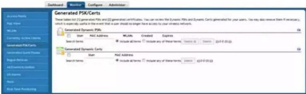
FIG. 11 Monitor Tab - Generated PSK/Certs
| Monitor Tab - Generated PSK/Certs | |
| Generated Dynamic PSKs: This is a list of the generated dynamic PSKs created and managed through the NXA-WAPZD1000. | |
| User: The name of the PSK user. | |
| MAC Address: The MAC address for the PSK user. | |
| WLANs: The WLANs to which the PSK allows access. | |
| Created: The date the PSK was created. | |
| Expires: The date the PSK expires. | |
| Generated Dynamic Certs: | This is a list of the generated dynamic certifications created andmanaged through the NXA-WAPZD1000 |
| User: The name of the certification user. | |
| MAC Address: The MAC address of the certification user. | |
Managing Automatically Generated User Certificates and Keys
When using the internal user database, automatically generated user certificates and keys are deleted whenever the associated user account is deleted from the user database. In the case of using Windows Active Directory Server, LDAP or RADIUS server as an authentication server, to delete the generated user keys and certificates:
- Go to Monitor > Generated PSK/Certs.
- Select the check boxes for the PSKs and Certificates that you want to delete.
- Click Delete to delete the selected items.
The selected PSKs and Certificates are deleted from the system. A user with a deleted PSK or a deleted certificate will not be able to connect to the wireless network without obtaining a new key or a new certificate.
Generated Guest Passes
The Generated Guest Passes page lists all generated guest passes managed by the NXA-WAPZD1000. You can review the guest passes generated for your users, and also remove them if necessary.
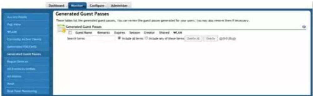
FIG. 12 Monitor Tab - Generated Guest Passes
| Monitor Tab - Generated Guest Passes | |
| Generated Guest Passes: | This collects a list of all guest passes currently being managed by the NXA-WAPZD1000. |
| Guest Name: The name of the guest accessing the network. | |
| Remarks: (Optional) Type any notes or comments. For example, if the guest user is a visitor from a partner organization, you can type the name of the organization. | |
| Expires: The date the guest pass expires: | |
| Session: Enable this check box and select a time increment after which guests will be required to log in again. If this feature is disabled, connected users will not be required to re-log in until the guest pass expires. | |
| Creator: The name of the creator of the guest pass. | |
| Shared: This notes whether or not the guest pass is shared with other users. | |
| WLAN: Select one of the existing WLANs with which the guest user will be allowed to associate. | |
Rogue Devices
As contrasted with “neighboring” access points (APs) that are parts of a neighboring WLAN, “rogue” (unauthorized) APs pose problems for a wireless network. Usually, a rogue AP appears in the following way: an employee obtains another manufacturer's AP and connects it to the LAN, to gain wireless access to other LAN resources. This would potentially allow even more unauthorized users to access your corporate LAN posing a security risk. Rogue APs also interfere with nearby authorized APs, thus degrading overall wireless network coverage.
Your NXA-WAPZD1000 rogue detection options include identifying the presence of a rogue AP, and locating it on your worksite floorplan prior to its removal. You can also mark rogue APs as "Known" if they are located in a neighboring network — outside your worksite — and pose no threat.
![Rogue Devices This folder lets unknown access points that might pose a security threat to your network if connected to the LAV. If a rogue device neither poses a thread our interference with network coverage, click Alert as known, which neutralizes that AP's effect on ZoneDirector and on web interface monitoring. Currently Active Rogue Devices MAC Address Channel Radio Type Encryption SSD Last Detected Action 00:42:e3:46:99:47 1 $02.118/g AP (Ethernet-connected) Encrypted WPT [2] Character SSD 2011/01/03 12:53:12 Work As Status 00:16:f5a:29:71:42 6 $02.118/g AP Encrypted freight 2011/01/03 12:53:12 Work As Status 00:16:f5a:29:71:41 4 $02.118/g AP Encrypted mtwater@p 2011/01/03 13:53:12 Work As Status 00:16:f5a:29:71:44 4 $02.118/g AP Encrypted EXPREF 2011/01/03 13:49:52 Work As Status 00:12:f5a:30:48:23 1 $02.118/g AP Encrypted ATL 2011/01/03 12:53:12 Work As Status 00:16:f5a:29:71:45 4 $02.118/g AP Encrypted freight 2011/01/03 13:49:52 Work As Status 00:16:f5a:29:71:43 4 $02.118/g AP Encrypted test pipe 2011/01/03 13:53:12 Work As Status Search terms: Include all terms Include any of these terms Known/Recognized Rogue Devices MAC Address Channel Radio Type Encryption SSD Last Detected 00:12:f5a:48:d00 1 $02.118/g AP Encrypted Steelpacket_jg 2011/01/03 13:53:12 00:16:f5a:29:71:42 6 $02.118/g AP Encrypted test_8d2* 2011/01/03 13:53:12 00:16:f5a:29:71:40 4 $02.118/g AP Encrypted freight 2011/01/03 13:53:12 00:12:f5a:7f:4c* 1 $02.118/g AP Encrypted p-v 2011/01/03 13:53:12 Search terms: Include all terms Include any of these terms: Session G3-1-4 (A)](/content/2026/05/897082/images/f99faf9c26e9450ef422580f28979b9f6b60a4449b52f118f12f29fe4b485c27.jpg)
FIG. 13 Monitor Tab - Rogue Devices
| Monitor Tab - Rogue Devices | |
| Currently Active Rogue Devices: | This is the complete list of all active rogue devices currently connecting to the network. |
| MAC Address: The MAC address | of the rogue device. |
| Channel: The radio channel being | used by the rogue device. |
| Radio: The radio frequency being | used by the rogue device. |
| Type: The type of device being used to access the network. | |
| Encryption: This notes whether the connection is encrypted or open. | |
| SSID: The SSID of the rogue device. | |
| Last Detected: The last time the rogue device was detected on the network. | |
| Action: | Click the Mark as Known link for the NXA-WAPZD1000 to recognise this device as authorized. |
| Known/Recognized Rogue Devices: | This is a list of all rogue devices that are recognized by the network as being authorized or safe. |
| MAC Address: The MAC address | of the rogue device. |
| Channel: The radio channel being | used by the rogue device. |
| Radio: The radio frequency being | used by the rogue device. |
| Type: The type of device being used to access the network. | |
| Encryption: This notes whether the connection is encrypted or open. | |
| SSID: The SSID of the rogue device. | |
| Last Detected: The last time the rogue device was detected on the network. | |
To detect a rogue AP:
- Go to Monitor > Rogue Devices.
- Look under Devices Overview for “# of Rogue Devices”.
- If at least once rogue device is detected, click the number for more details.
- When the Monitor > Rogue Devices page appears, two tables are listed:
• The Currently Active Rogue Devices table
● The Known/Recognized Rogue Devices table.
-
Review the Currently Active Rogue Devices table. The following types of Rogue APs generate an alarm when the NXA-WAPZD1000 detects them:
-
AP: An access point unknown to the NXA-WAPZD1000.
- AP (SSID-spoof): A rogue AP that uses the same SSID as the NXA-WAPZD1000's AP, also known as Evil-twin AP.
- AP (MAC-spoof): A rogue AP that has the same BSSID (MAC) of one of the virtual APs managed by the NXA-WAPZD1000.
-
Ad-hoc: A wireless adapter in ad-hoc mode. The Encryption column indicates if a rogue device is encrypted or is open.
-
If a listed AP is part of another, nearby neighbor network, click Mark as Known. This identifies the AP as posing no threat, while copying the record to the Known/Recognized Rogue Devices table.
-
To locate rogue APs that do pose a threat to your internal WLAN, click the MAC Address of a device to open the Map View (page 27). If your worksite floorplan is imported into the Map View window and your APs are positioned on the map, rogue APs can be generally identified with relative accuracy.
- After opening the Map View, look for the Rogue APs icon (page 28). This provides a clue to their location. You can now find the rogue APs and disconnect them. Or, if a rogue AP is actually a component in a neighboring network, you can mark it as "known".
If your office or worksite is on a single floor in a multistory building, your upper- and lower-floor neighbors' wireless access points may show up on the Map View, but seemingly in your site. As the NXA-WAPZD1000 cannot locate them in vertical space, you may need to do a bit more research to determine where the AP is located and if it should be marked as "Known."

All Events/Activities
This workspace displays the most recent records in the NXA-WAPZD1000's internal log file.
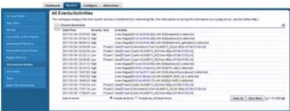
FIG. 14 Monitor Tab - All Events/Activities
| Monitor Tab - All Events/Activities | |
| Events/Activities: This is a complete list of events and activities recorded by the NXA-WAPZD1000. | |
| Date/Time: The date and time of the event. | |
| Severity: The security risk of the event. | |
| User: The user instigating the event. | |
| Activities: Details on the event. | |
| Clear All: | Click this button to clear all activity logs on the NXA-WAPZD1000. |
| Show More: Click this button to display another 15 events. | |
Changing the System Log Settings
The NXA-WAPZD1000 maintains an internal log of current events and alarms. This file has a fixed capacity; at a certain level, the device will start deleting the oldest entries to make room for the newest. This log is volatile, and the contents will be deleted if the device is powered down. If you want a permanent record of all logging activities, you can set up your syslog server to receive log contents from the NXA-WAPZD1000, and then use the Browser-Based Configuration Pages to direct all logging to the syslog server.
Reviewing the Current Log Contents
To review the current internal log:
-
Go to Monitor > All Events/Activities.
-
Review the events and alarms listed below.

Log entries are listed in reverse chronological order (with the latest logs at the top of the list).
-
Click a column header to sort the contents by that category.
-
Click any column twice to switch chronological or alphanumeric sorting modes.
Clearing Recent Events/Activities
To review the current events and, if appropriate, clear all resolved events:
-
Go to Monitor > All Events/Activities.
-
The Events/Activities table lists the unresolved events, the most recent at the top.
-
Review the contents of this table.
-
You can click Clear All at the bottom of the table to resolve and clear all events in the view.
All Alarms
If an alarm condition is detected, the NXA-WAPZD1000 will record it in the events log, which, if configured, will send an email warning.
![All Alarms This workplace data is all cleaned alarms. If all listed alarms have been cleaned or are no longer valids, click Clear 46. Alarms Date/Time Name Severity Activities Action 2011-01-04 07:09:52 Rogue AP Detected High a new Rogue[30:16:7a:29:8c:16] with [50]o=neutral] is detected Case 2011-01-04 07:04:12 Rogue AP Detected High a new Rogue[30:16:7a:29:8c:18] with [50]o=neutral] is detected Case 2011-01-04 06:04:12 Rogue AP Detected High a new Rogue[30:16:7a:29:8c:18] with [50]o=neutral; g_pudar] is detected Case 2011-01-03 22:33:12 Rogue AP Detected High a new Rogue[30:16:5a:9b:22:9c] with [50]o=neutral] is detected Case 2011-01-03 22:39:12 Rogue AP Detected High a new Rogue[30:25:4a:18:2a:2c] with [50]o=TTG_Lak] is detected Case 2011-01-03 18:57:52 Rogue AP Detected High a new Rogue[30:43:4a:18:5w:13] with [50]o=neutral; g_pudar] is detected Case 2011-01-03 18:57:52 Rogue AP Detected High a new Rogue[30:43:4a:18:5w:13] with [50]o=neutral; g_pudar] is detected Case 2011-01-03 18:00:32 Rogue AP Detected High a new Rogue[30:43:4a:18:5w:17] with [50]o=neutral] is detected Case 2011-01-03 18:41:52 Rogue AP Detected High a new Rogue[30:43:4a:18:5w:17] with [50]o=neutral; g_pudar] is detected Case 2011-01-03 18:30:32 Rogue AP Detected High a new Rogue[a:c:47b:7f:7(2a:c)] with [50]o=nucleus; p) is detected Case 2011-01-03 18:42:12 Rogue AP Detected High a new Rogue[30:43:4a:18:5w:14] with [50]o=nucleus; p) is detected Case 2011-01-03 18:42:12 Rogue AP Detected High a new Rogue[30:43:4a:18:5w:18] with [50]o=nucleus; p) is detected Case 2011-01-03 15:39:12 Rogue AP Detected High a new Rogue[a:c:47b:7f:7(2a:c)] with [50]o=nucleus; p) is detected Case 2011-01-03 15:39:12 Rogue AP Detected High a new Rogue[a:c:47b:7f:7(2a:c)] with [50]o=nucleus; p) is detected Case 2011-01-03 14:38:52 Rogue AP Detected High a new Rogue[30:43:4a:18:5w:14] with [50]o=neutral; g_pudar] is detected Case Search terms include all terms Include any of these terms Color # Share Mask C-1-15 (TTO A)](/content/2026/05/897082/images/0b50135321d7fb45b49bc9205030eefd522f14b3b349cf0d0fbfe5b5d811ce86.jpg)
FIG. 15 Monitor Tab - All Alarms
| Monitor Tab - All Alarms | |
| Alarms: This section lists all alarms | uncleared by the NXA-WAPZD1000 administrator. |
| Date/Time: The date and time when the alarm was triggered. | |
| Name: The alarm type (i.e. “Rogue AP”). | |
| Severity: The severity level of the alarm. | |
| Activities: Specifics on the activity that set off the alarm. | |
| Action: | Click the Clear link to remove this alarm from the listing. |
To review the current alarms and clear all resolved alarm records:
- Go to Monitor > All Alarms.
- The Alarms table lists the unresolved alarms, the most recent at the top.
- Review the contents of this table.
- If a listed alarm condition has been resolved, click the now-active Clear link to the right. You also have the option of clicking Clear All to resolve all alarms at one time.
Mesh
This workspace shows the mesh status and mesh topology.
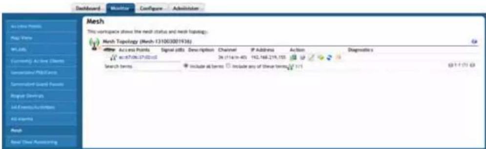
FIG. 16 Monitor Tab - Mesh
| Monitor Tab - Mesh | |
| Mesh Topology(Mesh-131003001936) | This table shows the current mesh network topology between APs and the NXA-WAPZD1000. |
| Access Points: The current APs connected to the NXA-WAPZD1000. | |
| Signal (dB): The current signal strength of the mesh network connection. | |
| Description: (Optional) A more detailed description of the mesh network connection. | |
| Channel: The radio channel being used to maintain the mesh network. | |
| IP Address: The IP address of the AP. | |
| Action: | Select between the icons to perform a specific action:System Info, RF Info. Configure, Troubleshoot Your Network Connectivity. Restart, or SpeedFlex. |
| Diagnostics: This entry lists all diagnostics, if any, being used on this AP. | |
Real Time Monitoring
The Real Time Monitoring tool provides a convenient at-a-glance overview of performance statistics such as CPU and memory utilization, number of APs and clients on the network, and number of packets transmitted.
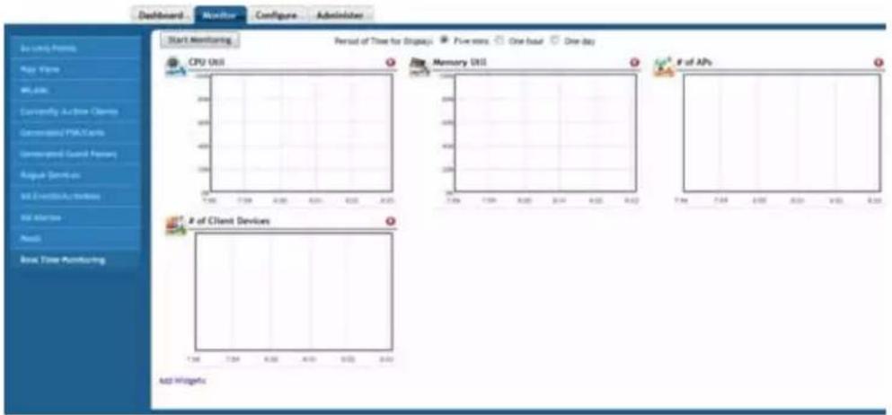
FIG. 17 Monitor Tab - Real Time Monitoring
The Real Time Monitoring tool provides a convenient at-a-glance overview of performance statistics such as CPU and memory utilization, number of APs and clients on the network, and number of packets transmitted..
The Real Time Monitoring function may also be accessed from the Toolbox link at the top of the Browser-Based Configuration Pages.

| Monitor Tab - Real Time Monitoring | |
| Start Monitoring button: Click this button to start monitoring. | |
| CPU Util: Displays the percentage utilization of the NXA-WAPZD1000's CPU. | |
| Memory Util: Displays the percentage utilization of the NXA-WAPZD1000's memory. | |
| # of APs: Displays the number of wireless access points being managed by the NXA-WAPZD1000. | |
| # of Client Devices: | Displays the number of client devices associated to access points being managed by the NXA-WAPZD1000. |
| Bytes Received: Total bytes received by all access points being managed by the NXA-WAPZD1000. | |
| Bytes Transmitted: Total bytes received by all access points being managed by the NXA-WAPZD1000. | |
| Packets Received: Total packets received by all access points being managed by the NXA-WAPZD1000. | |
| Packets Transmitted: Total packets transmitted by all access points being managed by the NXA-WAPZD1000. | |
To begin Real Time Monitoring, select a time increment (5 minutes, 1 hour or 1 day) and click Start Monitoring to begin. Note that because the Real Time Monitoring process itself consumes a small amount of system resources, it should be used as a general overview tool rather than a precise measurement. Actual resources used (CPU and memory utilization) will be lower when Real Time Monitoring is not running.
Configure Tab
The Configure Tab contains the tools necessary to configure and maintain a NXA-WAPZD1000 network. This tab includes access to WLAN specifications, identification of users, guest access, and configuration of mesh networks.

NOTE
When making any changes in the Browser-Based Configuration Pages, you must click Apply before you navigate away from the page or your changes will not be saved.
System
The majority of the NXA-WAPZD1000's general system settings can be accessed from the System page under the Configure Tab in the Browser-Based Configuration Pages. A basic set of parameters is configured during the Setup Wizard process. These parameters and others can be customized on this page.
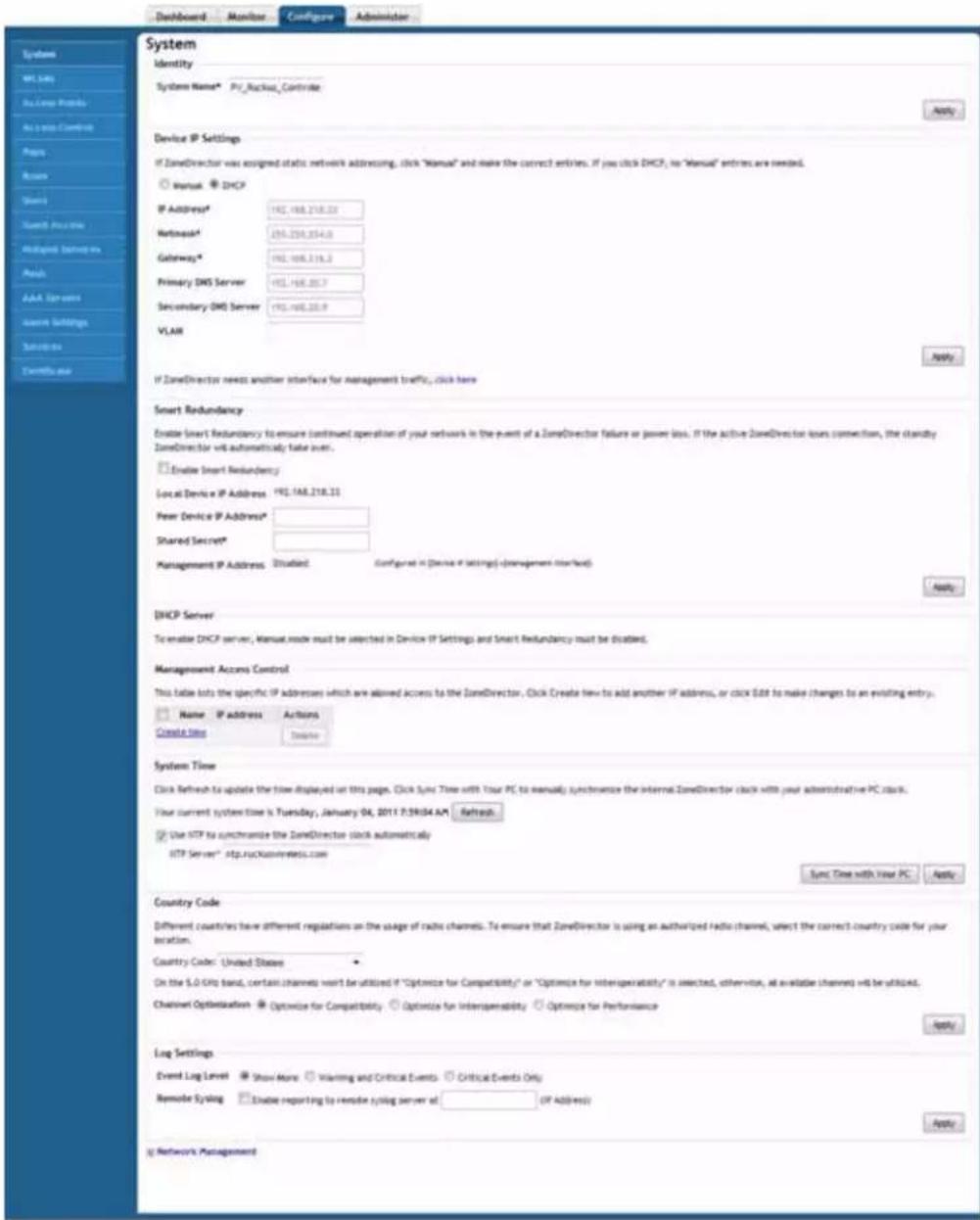
FIG. 18 Configure Tab - System
| Configure Tab - System | |
| System Name: The currently chosen name for the NXA-WAPZD1000 network. | |
| Device IP Settings: | The current IP settings for the NXA-WAPZD1000. If “Manual” is selected, these fields must be filled by the operator. If “DHCP” is selected, these fields are automatically filled by the network. |
| Configure Tab - System (Cont.) | |
| IP Address: The current IP address being used. | |
| Netmask: The current netmask being used. | |
| Gateway: The current gateway being used. | |
| Primary DNS Server: The current primary DNS server being used. | |
| Secondary DNS Server: The secondary DNS server being used. | |
| VLAN: The VLAN setting being used. | |
| Management Interface Click the "Enable Management Interface" link to open the Management Interface. | |
| Enable Management Interface: Check this box to allow information to be entered in the Management Interface fields. | |
| IP Address: The IP address for the server used for management. | |
| Netmask: The netmask for the server used for management. | |
| VLAN: The VLAN for the server used for management. | |
| Smart Redundancy: Smart Redundancy allows continued operation of your network in the event of an NXA-WAPZD1000 failure or power loss by allowing a connection to a second NXA-WAPZD1000. If the active NXA-WAPZD1000 loses connection, the standby device automatically takes over. | |
| Enable Smart Redundancy: Click this box to enable the Smart Redundancy fields. | |
| Local Device IP Address: The current IP address for the active NXA-WAPZD1000 in the network | |
| Peer Device IP Address: The IP address for the standby NXA-WAPZD1000. | |
| Shared Secret: A shared password to be used between the active and standby NXA-WAPZD1000 devices. | |
| Management IP Address: The IP address for the server used to manage the network. (If the Management Interface has not been enabled, this field will be disabled.) | |
| Management Access Control: This section lists the specific IP addresses which are allowed access to the NXA-WAPZD1000. | |
| Name: The name of the device or network accessing the NXA-WAPZD1000. | |
| Restriction: Select between "Single," "Range," and "Subnet".• Single: allows only one specific IP address.• Range: allows all IP addresses within a predetermined range.• Subnet: allows all IP addresses within a predetermined subnet range. | |
| IP Address: The IP address or address range, depending upon the chosen Restriction. | |
| System Time: Click the Refresh button to update the displayed time and date, Click the Sync Time With Your PC button to synchronize the NXA-WAPZD1000's time with your PC. After choosing to synchronize the time with your PC, click the Apply button to update the time. | |
| NTP Server: Check the Use NTP to synchronize the NXA-WAPZD1000 clock automatically box to access a particular NTP server for the current time. Enter the URL of the NTP server to be accessed in the NTP Server field. | |
| Country Code: Select the country in which the NXA-WAPZD1000 is being used. | |
| Channel Optimization: Select between the three options to optimize for compatibility, interoperability, or performance. | |
| Log Settings: | |
| Event Log Level: Select the level by which network events will be logged. | |
| Remote Syslog: Click the Enable Syslog box to allow logging to be conducted by a remote server. Enter the server IP address to allow remote logging. | |
Changing the System Name
When you first worked through the Setup Wizard, you were prompted for a network-recognizable system name for the NXA-WAPZD1000. If needed, you can change that name by following these steps:
- In the Browser-Based Configuration Pages, click the Configure Tab to bring up the System page.
- In the System Name field (under Identity), delete the text, and then type a new name. The name should be between 6 and 32 characters in length, using letters, numbers, underscores (_) and hyphens (-). Do not use spaces or other special characters. The first character must be a letter. System names are case sensitive.
- Click Apply to save your settings. The change goes into effect immediately.
Changing the Network Addressing
If you need to update the IP address and DNS server settings of the NXA-WAPZD1000, follow the steps outlined below.

As soon as the IP address has been changed, you will be disconnected from your Browser-based Configuration Page connection to the NXA-WAPZD1000 You can log into the Browser-Based Configuration Pages again by using the new IP address in your Web browser.
- In the Browser-Based Configuration Pages, click the Configure Tab to bring up the System page.
- Review the Device IP Settings options.
-
Select one of the following:
-
Manual: If you select Manual, enter the correct information in the now-active fields (IP Address, Netmask, and Gateway are required).
-
DHCP: If you select DHCP, no further information is required.
-
Click Apply to save your settings. You will lose your connection to the NXA-WAPZD1000.
- To log back into the Browser-Based Configuration Pages, use the newly assigned IP address in your Web browser or use the UPnP application to rediscover the NXA-WAPZD1000.
Enabling The Built-in DHCP Server
The NXA-WAPZD1000 comes with a built-in DHCP server that you can enable to assign IP addresses to devices that are connected to it. The NXA-WAPZD1000's DHCP server will only assign addresses to devices that are on its own subnet and part of the same VLAN (if VLANs are assigned).
Note that before you can enable the built-in DHCP server, the NXA-WAPZD1000 must be assigned a manual (static) IP address. If you configured the device to obtain its IP address from another DHCP server on the network, the options for the built-in DHCP server will not be visible on the System page.
Enabling the built-in DHCP server should only be done if no other DHCP servers are available on the network. Note that the DHCP server in the NXA-WAPZD1000 can support only a single subnet. If you enable the built-in DHCP server, enabling the rogue DHCP server detector is highly recommended.
To enable the built-in DHCP server:
- Click the Configure tab. The System page appears.
- Under the DHCP Server section, select the Enable DHCP check box.
- In Starting IP Address, type the first IP address that the built-in DHCP server will allocate to DHCP clients.
- Note that the starting IP address must be on the same subnet as the IP address assigned to the device. If the value that you typed is invalid, an error message appears and prompts you to let the device automatically correct the value. Click OK to automatically correct the entry.
- In Number of IP, type the maximum number of IP addresses that you want to allocate to requesting clients. The built-in DHCP server can allocate up to 255 IP addresses, including the one assigned to the device. The default value is 200.
- In Lease Time, select a time period for IP addresses to be allocated to DHCP clients. Options range from six hours to two weeks (default is one week).

- If your APs are on different subnets from the device, click the check box next to DHCP Option 43 to enable Layer 3 discovery of the NXA-WAPZD1000 by the APs.
- Click Apply.

If you typed an invalid value in any of the text boxes, an error message appears and prompts you to let the NXA-WAPZD1000 automatically correct the value. Click OK to change it to a correct value.
Viewing DHCP Clients
To view a list of current DHCP clients, click the click here link at the end of the “To see all currently assigned IPs by DHCP server...” sentence. A table appears and lists all current DHCP clients with their MAC addresses, assigned IP addresses, and the remaining lease time.
Enabling an Additional Management Interface
The additional management interface is created for receiving or transmitting management traffic only. The management IP address can be configured to allow an administrator to access the NXA-WAPZD1000 remotely from a different subnet from the AP network.
It can also be used for Smart Redundancy -- when redundant NXA-WAPZD1000s are deployed, you can create a separate management interface to be shared by both devices. This shared management IP address is enabled under the Device IP Settings section, and must be configured identically on both NXA-WAPZD1000s. For more information on Smart Redundancy, please refer to the Enabling Smart Redundancy section on page 17.
To enable an additional management interface:
- Go to Configure > System.
- In the Device IP Settings section, click the Click Here link next to the text "If ZoneDirector needs another interface for management traffic..."
- Click the box next to Enable Management Interface, and enter the IP Address, Netmask and VLAN information for the additional interface.
- Click Apply to save your settings.
- If the Management Interface is to be shared by two devices, repeat steps 1-5 for the other NXA-WAPZD1000.

If a management interface is used for Web UI management, the actual IP address must still be used when configuring the NXA-WAPZD1000 as a client for a backend RADIUS server or in any SNMP systems. If two devices are deployed in a Smart Redundancy configuration, both of the actual IP addresses must be used rather than the management IP address.
Checking the Current Log Settings
To review and customize the internal log settings:
- Go to Configure > System.
- Scroll down to Log Settings.
- Make your selections from these syslog server options:
- Event Log Level: Select one of the three logging levels: "Show More," "Warning and Critical Events," or "Critical Events Only."
-
Remote Syslog: To enable syslog logging, select the “Enable reporting to remote syslog server at” check box, and then type the IP address in the box provided.
-
Click Apply to save your settings. The changes go into effect immediately.
Setting the System Time
The NXA-WAPZD1000 does not have an internal clock, and if the device is rebooted, it will lose the current time given to it by the configuring PC. Time-sensitive features--such as time-based WLANs and Smart Redundancy--will not function properly if the time is incorrect. Therefore, pointing the device to an NTP (Network Time Protocol) server, is recommended.
To link your NXA-WAPZD1000 to an NTP server:
1. Go to Configure > System.
-
The System Time features have the following options:
-
Refresh: Click this to update the NXA-WAPZD1000 display (a static snapshot) from the internal clock.
- Synch Time with your PC Now: If needed, click this to update the internal clock with the current time settings from your administration PC.
-
Use NTP... (Enabled by default): Clear this check box to disable this option, or enter the DNS name or IP address of your preferred NTP server to use a different one.
-
Click Apply to save the results of any resynchronization or NTP links.
Setting the Country Code
Different countries and regions maintain different rules that govern which channels can be used for wireless communications. Setting the Country Code to the proper regulatory region ensures that your network does not violate local and national regulatory restrictions, and the Browser-Based Configuration Pages can be used to define the country code for all APs under its control.
To set the Country Code to the proper location:
- Go to Configure > System.
- Locate the Country Code section, and choose your location from the pull-down menu.
- Click Apply to save your settings.
Enabling Management via FlexMaster
If you have a Ruckus Wireless FlexMaster server installed on the network, you can enable FlexMaster management to centralize monitoring and administration of the NXA-WAPZD1000 and other supported devices. The NXA-WAPZD1000 supports the following FlexMaster-deployed tasks:
● Firmware upgrade for both the NXA-WAPZD1000 and the APs that report to them
- Reboot
- Backup of NXA-WAPZD1000 settings
When the FlexMaster management option is enabled, you will still be able to access the Browser-Based Configuration Pages to perform other management tasks. By default, FlexMaster management is disabled.
To enable FlexMaster management
- Click Configure > System.
- Scroll down to the bottom of the page.
- If you see + Network Management (section is collapsed) at the bottom of the page, click the Network Management link to expand the section.
- Under FlexMaster Management (bottom of the page), select the Enable management by FlexMaster check box.
- In URL, type the FlexMaster DNS host name or IP address of the FlexMaster server.
- In Interval, type the time interval (in minutes) at which the device will send status updates to the FlexMaster server. The default interval is 15 minutes.
- Click Apply. The message Setting Applied appears.
Configuring SNMP Support
The NXA-WAPZD1000 provides support for Simple Network Management Protocol (SNMP) v2, which allows you to query NXA-WAPZD1000 information, such as system status, WLAN list, AP list, and clients list, and to set a number of system settings. You can also enable SNMP traps to receive immediate notifications for possible AP and client issues.
Enabling the SNMP Agent
- In the Network Management section of the System page, scroll down to the bottom of the page.
- Under the SNMP Agent section, select the Enable SNMP Agent check box.
- In SNMP RO community (required), set the read-only community string. Applications that send SNMP Get-Requests to the NXA-WAPZD1000 (to retrieve information) will need to send this string along with the request before they will be allowed access. The default value is public.
- In SNMP RW community (required), set the read-write community string. Applications that send SNMP Set-Requests to the NXA-WAPZD1000 (to set certain SNMP MIB variables) will need to send this string along with the request before they will be allowed access. The default value is private.
- In System Contact, type your email address (optional).
- In System Location, type the location of the NXA-WAPZD1000 (optional).
- Click Apply to save your changes.
Enabling SNMP Trap Notifications
If you have an SNMP trap server on the network, you can configure the NXA-WAPZD1000 to send SNMP trap notifications to the server. Enable this feature if you want to automatically receive notifications for AP and client events that indicate possible network issues.
To enable SNMP trap notifications
- In the Network Management section of the System page, scroll down to the bottom of the page.
- Under SNMP Trap, select the Enable SNMP Trap check box.
- In Trap Server IP, type the IP address of the SNMP trap server on the network.
- Click Apply to save your changes.
Trap Notifications Sent by the NXA-WAPZD1000
The NXA-WAPZD1000 will send trap notifications to the SNMP server for seven specified events.
| Trap Notifications | |
| Trap Name Description | |
| ruckusZDEventAPJoinTrap An AP has joined the NXA-WAPZD1000. The AP's MAC address is included in the trap notification. | |
| ruckusZDEventSSIDSpoofTrap An SSID-spoofing rogue AP has been detected on the network. The rogue AP's MAC address and SSID are included in the trap notification. | |
| ruckusZDEventMACSpoofTrap A MAC-spoofing rogue AP has been detected on the network. The rogue AP's MAC address and SSID are included in the trap notification. | |
| ruckusZDEventRogueAPTrap A rogue AP has been detected on the network. The rogue AP's MAC address and SSID are included in the trap notification. | |
| ruckusZDEventAPLostTrap An AP has lost contact with the NXA-WAPZD1000. The AP's MAC address is included in the trap notification. | |
| ruckusZDEventAPLostHeartbeatTrap | An AP's heartbeat has been lost. The AP's MAC address is included in the trap notification. |
| ruckusZDEventClientAuthFailBlockTrap | A wireless client repeatedly failed to authenticate with an AP. The client's MAC address, AP's MAC address and SSID are included in the trap notification. |
NXA-WAPZD1000 Management ACL
The NXA-WAPZD1000 also includes an access control feature for controlling access to the Browser-Based Configuration Pages. The Management Access Control interface is located on the Configure > System screen. Options include limiting access by subnet, single IP address and IP address range.

When you create a management access control rule, all IP addresses and subnets other than those specifically listed will be blocked from accessing the Browser-Based Configuration Pages.
To restrict access to the Browser-Based Configuration Pages:
- Go to Configure > System.
- Locate the Management Access Control section, and click the Create New link.
- In the Create New menu that appears, enter a name for the user(s) that you want to allow access to the Browser-Based Configuration Pages.
- Enter an IP address, address range or subnet.

The administrator's current IP address is shown for convenience--be sure not to create an ACL that prevents the admin's own IP address from accessing the Browser-Based Configuration Pages.
- Click OK to confirm. You can create up to 16 entries to the Management ACL.
WLANs
The WLANs page collects all of the configuration options for the WLANs currently being managed by the NXA-WAPZD1000.
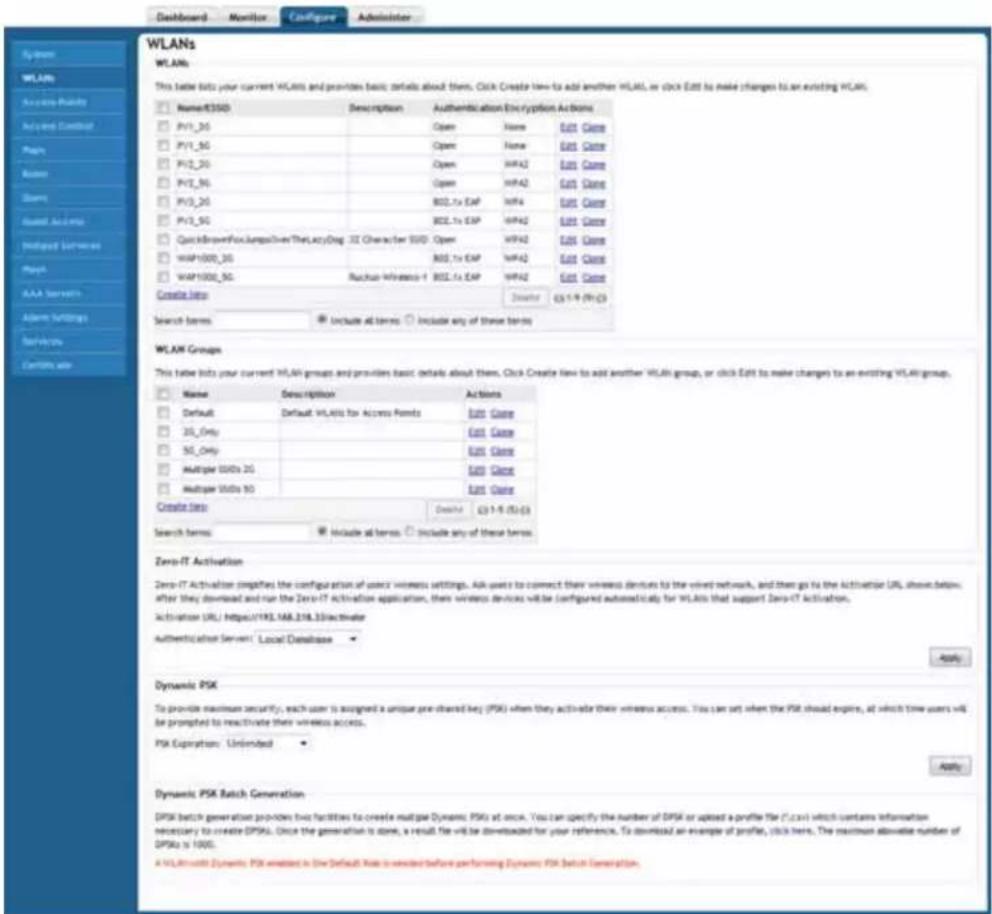
FIG. 19 Configure Tab - WLANs
| Configure Tab - WLANs | |
| WLANS: This table lists your current WLANs and provides basic details about them. | |
| Name/ESSID: The name of the individual WLAN. | |
| Description: (Optional) A more detailed description of the WLAN. | |
| Authentication: The type of authentication being used by the WLAN. | |
| Encryption: The type of encryption being used by the WLAN. | |
| Actions: | Select Edit to make changes to the WLAN and Clone to make an exact copy of the WLAN. |
| WLAN Groups: This table lists your current WLAN groups and provides basic details about them. | |
| Name: The name of the WLAN group. | |
| Description: (Optional) A more detailed description of the WLAN. | |
| Actions: | Select Edit to make changes to the group and Clone to make an exact copy of the group. |
| Configure Tab - WLANs (Cont.) | |
| Zero-IT Activation: | Zero-IT Activation simplifies the configuration of users' wireless settings. Ask users to connect their wireless devices to the wired network, and then go to the Activation URL shown below. After they download and run the Zero-IT Activation application, their wireless devices will be configured automatically for WLANs that support Zero-IT Activation. |
| Dynamic PSK: To provide maximum security, each user is assigned a unique pre-shared key (PSK) when they activate their wireless access. You can set when the PSK should expire, at which time users will be prompted to reactivate their wireless access. | |
| Dynamic PSK Batch Activation: | DPSK batch generation provides two facilities to create multiple Dynamic PSKs at once. You can specify the number of DPSK or upload a profile file (*.csv) which contains information necessary to create DPSKs. Once the generation is done, a result file will be downloaded for your reference. |
Overview of Wireless Networks
When you have completed the NXA-WAPZD1000 Setup Wizard, you have a fully functional wireless network, based on two secure WLANs (if you enabled the optional guest WLAN) with access for authorized users and guests. The internal WLAN provides Zero-IT connectivity for "standard" client devices, those clients running Windows XP SP2 (or later), Windows Vista, Windows 7, Mac OS X, iPhone and iTouch and utilizing WPA-ready NICs.
There are several scenarios in which you will want to create additional WLANs, in addition to the internal WLAN:
- To limit certain WLANs to groups of qualified users, to enhance security and efficiency (for example, an “Engineering” WLAN with a closed roster of users).
- To configure a specific WLAN with different security settings. For example, you may need a WLAN that utilizes WEP encryption for wireless handheld devices that only support WEPkey encryption.
- To create special WLANs with different settings for specific purposes. For example, a VoIP WLAN for voice traffic with background scanning and load balancing disabled, or a student WLAN that is only available during school hours.
In the first scenario, specific WLANs (esp. regarding authentication and encryption algorithm) can be set up that support specific groups of users. This requires a two-step process: (1) create the custom WLAN and link it to qualified user accounts by “roles,” and (2) assist all qualified users to prepare their client devices for custom WLAN connection.
As a result, you will have the default internal WLAN, plus the needed WLANs that fulfill different wireless security or user segmentation requirements.
Creating a WLAN
To create a new WLAN:
- Go to Configure > WLANs. The first table displays all WLANs that have already been created by the NXA-WAPZD1000.
- In the top section (WLANs), click Create New. The Create New workspace displays the following (FIG. 20):
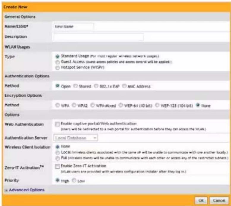
FIG. 20 WLANS - Create New
The WLAN Create New workspace includes the following configuration options used to customize your new WLAN:
| Create New WLAN Options | |
| Option Description | |
| General Options: Enter WLAN name and description.· Name/ESSID: Type a short name (2-31 characters/numbers) for this WLAN.· Description: Enter a brief description of the qualifications/purpose for this WLAN, e.g., “Engineering” or “Voice.” | |
| WLAN Usages: Select usage type (standard, guest access, hotspot). | |
| Authentication Options: Select authentication method (open, shared key, 802.1X EAP, MAC address). | |
| Encryption Options: Select encryption method (WPA, WPA2, WPAMixed, WEP), encryption algorithm and passphrase or WEP key.If any authentication method other than “open” or “MAC address” is selected, the “none” option for encryption method is disabled. | |
| Options: Select whether Web-based authentication (captive portal) will be used, and which type of authentication server will be used to host credentials (local database, Active Directory, RADIUS, LDAP).Also, enable or disable Wireless Client Isolation, Zero-IT Activation, Dynamic PSK and Priority for this WLAN. | |
| Create New WLAN Options (cONT.) | |
| Option Description | |
| Advanced Options: Select accounting server, ACLs, rate limiting, VLAN/ dynamic VLAN settings, tunneling, background scanning, maximum client threshold, and service schedule. | |
- When you finish, click OK to save the entries. This WLAN is ready for use.
- You can now select from these WLANs when assigning roles to users.
WLAN Usage Types
To create a WLAN with specific options, choose Standard Usage. If you have configured Hotspot services, you can enable Hotspot service on this new WLAN. Additionally, you can select a default Guest Access WLAN with open access and customizable encryption. Guest WLANs are subject to guest access policies, such as redirection and subnet access restrictions.

When Guest Usage or Wireless Client Isolation (below) is enabled, the SpeedFlex Wireless Performance tool may not function properly. For example, SpeedFlex may be inaccessible to users at http://{device-ip-address}/perf or SpeedFlex may prompt you to install the SpeedFlex application on the target client, even when it is already installed. Before using SpeedFlex, verify that both Guest Usage and Wireless Client Isolation options are disabled.
Authentication Method
Authentication Method defines the method by which users are authenticated prior to gaining access to the WLAN. The level of security should be determined by the purpose of the WLAN you are creating.
- Open [Default]: No authentication mechanism is applied to connections. If WPA or WPA2 encryption is used, this implies WPA-PSK authentication.
- Shared: If you click Shared, only WEP encryption will be available, and the WEP Key option appears. The Shared authentication type requires creation of a WEP key that is shared by all users.

Because WEP encryption is easily circumvented, Shared authentication provides little security and should not be used.
- 802.1X/EAP: Uses 802.1X authentication against a user database. Requires use of certificates.
- MAC Address: Uses the device's MAC address for both the user name and password.
Encryption Options
Encryption choices include WPA, WPA2, WPA-Mixed, WEP and none. WPA and WPA2 are both encryption methods certified by the WiFi Alliance and are the recommended encryption methods. The Wi-Fi Alliance will be mandating the removal of WEP because it is easily cracked, so it should not be used.
Method
- WPA: Standard Wi-Fi Protected Access with either TKIP or AES encryption.
- WPA2: Enhanced WPA encryption using the stronger AES encryption algorithm.
- WPA-Mixed: Allows mixed networks of WPA and WPA2 compliant devices. Use this setting if your network has a mixture of older clients that only support WPA and TKIP, and newer client devices that support WPA2 and AES.

Selection of WPA-Mixed disables the ability to enable Zero-IT for this WLAN.
- WEP-64: Provides a lower level of encryption, and is less secure, using 40-bit WEP encryption.
- WEP-128: Provides a higher level of encryption than WEP-64, using a 104-bit key for WEP encryption. However, WEP is inherently less secure than WPA.
- None: No encryption; communications are sent in clear text.

If you set the encryption method to WEP-64 (40 bit) or WEP-128 (104 bit) and you are using an 802.11n AP for the WLAN, the AP will operate in 802.11g mode.
Algorithm (Only for WPA or WPA2 encryption methods)
- TKIP: This algorithm provides greater compatibility with older client devices, but is not supported by the 802.11n standard. Therefore, if you select TKIP encryption, 11n devices will be limited to 11g transfer rates. Furthermore, the Wi-Fi Alliance will be mandating the removal of TKIP, so it should not be used.
- AES: This algorithm provides enhanced security over TKIP, and is the only encryption algorithm supported by the 802.11i standard. Choose AES encryption if you are certain that all of your clients will be using 802.11i-compliant NICs.
- Auto: Automatically selects TKIP or AES encryption based on the client's capabilities. Note that since it is possible to have clients using both TKIP and AES on the same WLAN, only unicast traffic is affected (broadcast traffic must fall back to TKIP; therefore, transmit rates of broadcast packets from 11n APs will be at lower 11g rates).

If you set the encryption algorithm to TKIP and you are using an 802.11n AP for the WLAN, the AP will operate in 802.11g mode.

If you set the encryption algorithm to TKIP, the AP will only be able to support up to 25 clients. When this limit is reached, additional clients will be unable to associate with the AP. On the other hand, if you disable encryption or select AES, the AP will be able to support up to 100 clients per radio. If the wireless mesh network is also enabled, the AP will be able to support less than 100 clients per radio.
WEP Key/Passphrase
- WEP Key: WEP methods only. Click in the Hex field and type the required key text. If the key is for WEP 64 encryption, the key text must be up to 10 characters in length. If it is for WEP 128 encryption, enter a key up to 26 characters in length.
- Passphrase: WPA-PSK methods only. Click in this field and type the text of the passphrase used for authentication.
Options
- Web Authentication: [Available only with Open or Shared authentication.] Click the check box to require all WLAN users to complete a Web-based login to this network each time they attempt to connect.
- Authentication Server: When Web Authentication is active, use this option to designate the server used to authenticate Web-based user login. When 802.1X or MAC Address authentication is active, use this option to designate the server used to authenticate users (without Web authentication).
Options include Local Database, RADIUS server, Active Directory and LDAP. When one of these authentication server types is selected (other than Local Database), you will need to point the NXA-WAPZD1000 to the proper authentication server configured on the Configure > AAA Servers page.
- Wireless Client Isolation: Wireless client isolation enables subnet restrictions for connected clients. Options are:
None: Clients associated with this WLAN are not isolated and have full access to communicate with each other and any other nodes on the local network.
Local: Clients can not communicate with each other on the same WLAN, but can access other resources on the local network.
Full: When full wireless client isolation is enabled for a WLAN, stations associated to this WLAN will not be able to communicate with each other or access the local LAN; rather, they can only access the Internet. The behavior of stations will be exactly the same as the stations that associate to
a guest WLAN. The only difference between a WLAN with wireless client isolation enabled and a guest WLAN is that a guest WLAN requires users to enter a guest pass before they can access the network. The same guest policy will be applied to a guest WLAN as to a WLAN with wireless client isolation enabled.

The SpeedFlex wireless performance tool will not work properly if wireless client isolation is enabled on the WLAN. For example, SpeedFlex may be inaccessible to users at http://{NXA-WAPZD1000-ip-address}/perf or SpeedFlex may prompt you to install the SpeedFlex application on the target client, even when it is already installed.
- Zero-IT Activation: Leave this check box selected (the default state), as it activates the NXA-WAPZD1000's share in the automatic "new user" process, in which the new user's PC is easily and quickly configured for WLAN use.

For Zero-IT Activation to work on HP iPAQ, Internet Explorer Mobile 7.6 (or later) must be installed. If your HP iPAQ users are using earlier versions of Internet Explorer Mobile, upgrading to the latest version before connecting to your wireless network is highly recommended.
- Dynamic PSK: Dynamic PSK is available when you have enabled Zero-IT Activation. When a client is activated, the NXA-WAPZD1000 provisions the user with a pre-shared key. This per-user key does not expire by default. If you want to set an expiration for Dynamic PSKs, you can do so from the drop-down menu further down the page.
- Priority: (Default: High). Set the priority of this WLAN to Low if you would prefer that other WLAN traffic takes priority. For example, if you want to prioritize internal traffic over guest WLAN traffic, you can set the priority in the guest WLAN configuration settings to Low. By default all WLANs are set to high priority.
Advanced Options
The advanced options can be used to configure special WLANs; for example, you might want to create a special WLAN for VoIP phone use only, or create a student WLAN that should be time-controlled to provide access only during school hours.
- Accounting Server: If you added a RADIUS Accounting server on the AAA servers page, select the RADIUS Accounting server from the drop-down list, and then set the accounting update interval in Send Interim-Update every x minutes. Note that this option is only available if:
- Authentication Option is set to 802.1X EAP.
- Authentication Option is set to Open or Shared, and Web Authentication is enabled.
- Access Controls: Toggle this drop-down list to select the ACL to apply to this WLAN. An ACL must be created before being available here.
- Rate Limiting: Rate limiting controls fair access to the network. When enabled, the network traffic throughput of each network device (i.e., client) is limited to the rate specified in the traffic policy, and that policy can be applied on either the uplink or downlink.
Toggle the Uplink and/or Downlink drop-down lists to limit the rate at which WLAN clients upload/download data.
The Disabled state means rate limiting is disabled; thus, traffic flows without prescribed limits.
- VLAN: By default, all wireless clients associated with APs that the NXA-WAPZD1000 is managing are segmented into a single VLAN (with VLAN ID 1). If you want to segment wireless clients into different VLANs, select the Enable Dynamic VLAN check box to allow the NXA-WAPZD1000 to assign VLAN IDs on a per-user basis. Before enabling dynamic VLAN, you need to define on the RADIUS server the VLAN IDs that you want to assign to users. If you want to change the default VLAN (VLAN ID 1) to which wireless clients are segmented, select the Set Default VLAN Tag to check box, and then type the VLAN ID that you want to set as default. The VLAN ID should be a number between 2 and 4094.
- Hide SSID: Activate this option if you do not want the ID of this WLAN advertised at any time. This will not affect the performance or force the WLAN user to perform any unnecessary tasks.
- Tunnel Mode: Select this check box if you want to tunnel the WLAN traffic back to the NXA-WAPZD1000. Tunnel mode enables wireless clients to roam across different APs on different subnets. If the WLAN has clients that require uninterrupted wireless connection (for example, VoIP devices and PDAs), enabling tunnel mode is recommended.
- Background Scanning: Background scanning enables the APs to continually scan for the best (least interference) channels and adjust to compensate. However, disabling background scanning may provide better quality (lower latency) for time-sensitive applications like voice conversations. If this WLAN will be used primarily as a voice network, select this check box to disable background scanning for this WLAN. You can also disable background scanning per radio.
- Load Balancing: Client load balancing between APs is enabled by default on all WLANs. To disable load balancing for this WLAN, check this box. Disabling load balancing on WLANs used for voice is recommended.
- Max Clients: Limit the number of clients that can associate with this WLAN per AP (default is 100). You can also limit the total number of clients that a specific AP will manage (or radio, on dual radio APs).
- 802.11d: The 802.11d standard provides specifications for compliance with additional regulatory domains (countries or regions) that were not defined in the original 802.11 standard. Enable this option if you are operating in one of these additional regulatory domains.
- Service Schedule: Use the Service Schedule tool to control which hours of the day, or days of the week to enable/disable WLAN service. For example, a WLAN for student use at a school can be configured to provide wireless access only during school hours. Click on a day of the week to enable/disable this WLAN for the entire day. Colored cells indicate WLAN enabled. Click and drag to select specific times of day. You can also disable a WLAN temporarily for testing purposes, for example.

NOTE
This feature will not work properly if the NXA-WAPZD1000 does not have the correct time. To ensure the NXA-WAPZD1000 always maintains the correct time, configure an NTP server and point the NXA-WAPZD1000 to the NTP server's IP address, as described in the Setting the System Time section on page 48.

NOTE
WLAN service will be enabled and disabled based on the NXA-WAPZD1000's system time, and not the time zone where the access point is located. These may be different local times if the NXA-WAPZD1000 and the access points are in different time zones.
Creating a New WLAN for Workgroup Use
If you want to create an additional WLAN based on your existing internal WLAN and limit its use to a select group of users (e.g., Marketing, Engineering), you can do so by following these steps:
- Make a list of the group of users (who ideally are using client devices running Windows XP SP2, Windows Vista SP1, Windows 7 or Mac OS X, or iPhone or iTouch handhelds).
- Go to Configure > WLANs. When the WLANs page appears, the default internal and guest networks are listed in the table (once you have created a WLAN, it will appear in this table).
- If you have no need for custom authentication or encryption methodologies in this new WLAN, locate the Internal WLAN record and click Clone. A workspace appears, displaying the default settings of a new WLAN, using the same Zero-IT configuration settings as Internal.
- Type a descriptive name for this WLAN, and then click OK. This new WLAN is ready for use by selected users.
Customizing WLAN Security
The default security environment for your internal WLAN incorporates a WPA-based authentication passphrase and the AES encryption algorithm, and utilizes a dynamic pre-shared key. To review the default WLAN configurations and the available options (customize the existing WLAN setup or replace it with a totally different configuration), review the following procedures.
To review the Initial Security Configuration:
-
Go to Monitor > WLANs.
-
When the WLANs workspace appears, a WLANs table lists the two default WLANs created in the setup process: internal and guest. The internal WLAN is the one used by your authorized users, and you can review the details of its configuration by clicking the WLAN name.
-
You have three options with the internal WLAN: [1] continue using the current configuration, [2] fine-tune the existing WPA-based mode, or [3] replace this mode entirely with either an 802.1X mode (recommended) or a WEP-based mode. The two WLAN-editing processes are described separately, below.
Fine-Tuning the Current Security Mode
To keep the original WPA security mode and fine-tune its settings:
- Go to Configure > WLANs.
- In the Internal WLAN row, click Edit.
-
You can choose from the following options, which will enhance the default Internal WLAN's security without disrupting the user's connections.
-
WPA2: Switch to this encryption method if you prefer the IEEE 802.11i standard, which provides the highest level of security, but is limited to devices with newer wireless NICs.
- WPA-Mixed: Allows both WPA and WPA2 compliant devices to access the network.
- AES: Switch to this algorithm for stronger encryption.
-
Passphrase: Replace the current passphrase with a new one, to help lower the risk of unauthorized access.
-
Click OK to apply any changes.
Switching to a Different Security Mode
You also have the option of replacing the default internal WLAN's WPA mode with one of two other modes:
● The less-secure protection of a WEP key mode
● The more-secure protection of an 802.1X mode
Replacing your WPA configuration with 802.1X requires the users to make changes to their wireless connection configuration, which may include the importation of certificates.
- Go to Configure > WLANs.
- When the WLAN workspace appears, you will want to review and then change the security options for the internal network. To start, click Edit in the Internal WLAN row.
- When the Editing (Internal) options appear, look at the two main categories -- Authentication Options and Encryption Options.
-
If you click an Authentication Option Method such as Open, Shared, or 802.1X, different sets of encryption options are displayed:
-
Open allows you to configure a WPA- or WEP-based encryption, or "none" if you're so inclined. After selecting a WPA or WEP level, you can then enter a passphrase or keytext of your choosing.
- . Shared limits you to WEP-key encryption.
- 802.1X EAP allows you to choose from all available encryption methods, but you do not need to create a key or passphrase.
- MAC Address allows you to use an external RADIUS server to authenticate wireless clients. Before you can use this option, you need to add your external RADIUS server to the Configure > AAA Servers page. You also need to define the MAC addresses that you want to allow on the RADIUS server.
-
Depending on your Authentication Option Method selection, review and reconfigure the related Encryption Options.
-
Review the Advanced Options to change any settings as needed. (For example, if you switch to 802.1X, you'll need to choose an authentication server from the menu.)
-
When you are finished, click OK to apply your changes.
Replacing your WPA configuration with 802.1X requires the users to make changes to theirS wireless connection configuration.including the importation of certificates.
Using the Built-in EAP Server
(Requires the selection of "Local Database" as the authentication server.) If you are re-configuring your internal WLAN to use 802.1X/EAP authentication, you normally have to generate and install certificates for your wireless users. With the built-in EAP server and Zero-IT Wireless Activation, certificates are automatically generated and installed on the end user's computer. Users simply follow the instructions
provided during the Zero-IT Wireless Activation process to complete this task. Once this is done, users can connect to the internal WLAN using 802.1X/EAP authentication.
Authenticating with an External RADIUS Server
You can also use an external RADIUS server for your wireless client 802.1X/EAP authentication. An EAP-aware RADIUS server is required for this application. Also, you might need to deploy your own certificates for wireless client devices and for the RADIUS server you are using. In this case, the NXA-WAPZD1000 works as a bridge between your wireless clients and the RADIUS server during the wireless authentication process.
The NXA-WAPZD1000 allows wireless clients to access the networks only after successful authentication of the wireless clients by the RADIUS server. For information on configuring a RADIUS server for client authentication, please refer to the RADIUS / RADIUS Accounting section on page 99.

If your wireless network is using EAP/external RADIUS server for client authentication and you have Windows Vista clients, make sure that they are upgraded to Vista Service Pack 1 (SP1). SP1 includes fixes for client authentication issues when using EAP external RADIUS server.
If You Change the Internal WLAN to WEP or 802.1X
If you replace the default WPA configuration of the internal WLAN, your users must reconfigure the wireless LAN connection settings on their devices. This process is described in detail below and can be performed when logging into the WLAN as a new user.
If you are switching to WEP-based security:
- Each user should be able to repeat the Zero-IT Wireless Activation process and install the WEP key by executing the activation script.
- Alternatively, they can manually enter the WEP key text into their wireless device connection settings. If you are switching to 802.1X-based security
- (Applies only to the use of the built-in EAP server.) Each user should be able to repeat the Zero-IT Wireless Activation process and download the certificates and an activation script generated by the NXA-WAPZD1000.
- Each user must first install certificates to his/her computer.
- Each user must then execute the activation script, in order to configure the correct wireless setting on his/her computer.
- To manually configure 802.1X/EAP settings for non-EAP capable client use, use the wireless settings generated by the NXA-WAPZD1000.
Working with WLAN Groups
If your wireless network covers a large physical environment (for example, multi-floor or multi-building office) and you want to provide different WLAN services to different areas of your environment, you can use WLAN groups to do this. For example, if your wireless network covers three building floors (1st Floor to 3rd Floor) and you need to provide wireless access to visitors on the 1st Floor, you can do the following:
- Create a WLAN service (for example, "Guest Only Service") that provides guest-level access only.
- Create a WLAN group (for example, “Guest Only Group”), and then assign “Guest Only Service” (WLAN service) to “Guest Only Group” (WLAN group).
- Assign APs on the 1st Floor (where visitors need wireless access) to your “Guest Only Group”.
Any wireless client that associates with APs assigned to the “Guest Only Group” will get the guest-level access privileges defined in your “Guest Only Service.” APs on the 2nd and 3rd Floors can remain assigned to the Default WLAN Group and provide normal-level access.

Creating WLAN groups is optional. If you do not need to provide different WLAN services to different areas in your environment, you do not need to create a WLAN group.

A default WLAN group called Default exists. The first eight WLANs that you create are automatically assigned to this Default WLAN group.

A WLAN Group can include a maximum of eight member WLANs. If Smart Mesh is enabled, the maximum number of WLANs in a WLAN group is six. For dual radio APs, each radio can be assigned to only one WLAN Group (single radio APs can be assigned to only one WLAN Group).
Creating a WLAN Group
To create a WLAN group:
- Go to Configure > WLANs.
- In the WLAN Groups section, click Create New. The Create New form appears.
- In Name, type a descriptive name that you want to assign to this WLAN group. For example, if this WLAN will contain WLANs that are designated for guest users, you can name this as Guest WLAN Group.
- In Description (optional), type some notes or comments about this group.
- Under Member WLANs, select the check boxes for the WLANs that you want to be part of this WLAN group.
- If you have existing VLANs on the network and you need to tag the traffic from the member WLANs, select the Enable VLAN override check box, and then configure the VLAN override settings for each member WLAN. Available options include:
- No Change: Click this option if you want the WLAN to keep the same VLAN tag (if you configured the Attach VLAN Tag option when you created the WLAN service).
- Untag: Click this option if a particular WLAN is connected to a local network that does not have any VLANs.
- Tag: Click this option if traffic from a particular WLAN needs to be tagged to bind with a VLAN successfully.
- Click OK. The Create New form disappears and the WLAN group that you created appears in the table under WLAN Groups.
You may now assign this WLAN group to an AP.
Assigning a WLAN to Provide Hotspot Service
After you create a hotspot service configuration, you need to specify the WLANs to which you want to deploy the hotspot configuration.
To configure an existing WLAN to provide hotspot service:
- Go to Configure > WLANs.
- In the WLANs section, look for the WLAN that you want to assign as a hotspot WLAN, and then click the Edit link that is on the same row. The Editing (WLAN name) form appears.
- In Type, click Hotspot Service (WISPr).
- In Hotspot Services, select the name of the hotspot service that you created previously.
- Click OK to save your changes.
Working with Dynamic Pre-Shared Keys
Dynamic PSK is a unique feature that enhances the security of normal Pre-shared Key (PSK) wireless networks. Unlike typical PSK networks, which share a single key amongst all devices, a Dynamic PSK network assigns a unique key to every authenticated user. Therefore, when a person leaves the organization, network administrators do not need to change the key on every device. Dynamic PSK offers the following benefits over standard PSK security:
- Every device on the WLAN has its own unique Dynamic PSK (DPSK) that is valid for that device only.
- Each DPSK is bound to the MAC address of an authorized device - even if that PSK is shared with another user, it will not work for any other machine.
- Since each device has its own DPSK, you can also associate a user (or device) name with each key for easy reference. Each DPSK may also have an expiration date - after that date, the key is no longer valid and will not work.
- DPSKs can be created and removed without impacting any other device on the WLAN.
- If a hacker manages to crack the DPSK for one client, it does not expose the other devices which are encrypting their traffic with their own unique DPSK.
When network users first activate their access to the WLAN with Dynamic PSK enabled, a unique pre-shared key (PSK) is generated automatically for their authentication. (This was activated by default in the WLAN Setup Wizard if you selected WPA-PSK as the WLAN Authentication method.)
Enabling Dynamic Pre-Shared Keys on a WLAN
To use DPSK for client authentication, you must enable it for a particular WLAN (if you did not enable it during the initial ZoneDirector Setup Wizard process).
To enable DPSK for a WLAN:
- Go to Configure > WLANs.
- Either Edit an existing WLAN or click Create New to open the WLAN configuration form.
- Under Type, select Standard Usage.
- Under Authentication Options: Method, select MAC Address or Open. (If Open, only Local Database is available as the authentication server.)
- Under Encryption Options: Method, select WPA or WPA2 (not WPA-Mixed, as selecting WPA-Mixed will disable the option to enable Zero-IT activation).
- If using MAC Address authentication, choose an Authentication Server to authenticate clients against, from either Local Database or RADIUS Server (if you chose Open, only Local Database is available).
- Ensure that the Zero-IT Activation check box is enabled.
- Next to Dynamic PSK, enable the check box next to Enable Dynamic PSK.
- Click OK to save your settings.
This WLAN is now ready to authenticate users using Dynamic Pre-Shared Keys, once their credentials are verified against either the internal database or an external RADIUS server.
Setting Dynamic Pre-Shared Key Expiration
By default, dynamic pre-shared keys do not expire. You can control when the PSK expires, at which time the users will be prompted to reactivate their wireless access.
To set the dynamic PSK expiration:
- Go to Configure > WLANs.
- In the Dynamic PSK section, select the PSK expiration time. Range includes one day to unlimited (never expires).
- Click the Apply button that is in the same section. The new setting goes into effect immediately.
If you change the dynamic PSK expiration period, the new expiration period will only be applied to new PSKs. Existing PSKs will retain the expiration period that was in effect when the PSKs were generated. To force expiration, go to Monitor >
Generated PSKs/Certs.
Generating Multiple Dynamic PSKs
If you will be generating DPSKs frequently (for example, to configure school-owned laptops in batch), you may want to generate multiple DPSKs at once and distribute them to your users in one batch. Before performing this procedure, check your WLAN settings and make sure that the Dynamic PSK check box is selected.
To generate multiple dynamic PSKs:
- Go to Configure > WLANs.
- Scroll down to the Dynamic PSK Batch Generation section.

- In Target WLAN, select one of the existing WLANs with which the users will be allowed to associate. (Only WLANs with DPSK enabled will be listed.)
- In Number to Create, select the number of dynamic PSKs that you want to generate. The NXA-WAPZD1000 will automatically populate the names of each user (BatchDPSK_User_1, BatchDPSK_User_2, and so on) to generate the dynamic PSKs.
- If you want to be able to identify the dynamic PSK users by their names (for monitoring or auditing purposes in a school setting, for example), click Browse, and upload a batch dynamic PSK profile instead.
- Click Generate. The NXA-WAPZD1000 generates the dynamic PSKs, and then the following message appears: To download the new DPSK record, click here
- Click the click here link in the message to download a CSV file that contains the generated dynamic PSKs.
You have completed generating the dynamic PSKs for your users. Using a spreadsheet application (for example, Microsoft Excel), open the CSV file and view the generated dynamic PSKs. The CSV file contains the following columns:
- User Name
- Passphrase
- WLAN Name
- MAC Address
- Expiration

The MAC address column shows 00:00:00:00:00:00 for all users. When a user accesses the WLAN using the dynamic PSK that has been assigned to him, the MAC address of the device that he used will be permanently associated with the dynamic PSK being used.
To enable wireless users to access the wireless network, you need to send them the following information:
- WLAN Name: This is the WLAN with which they are authorized to access and use the dynamic PSK that you generated (passphrase).
- Passphrase: This is the network key that the user needs to enter on his WLAN configuration client to access the WLAN.
- Expiration: (Optional) This is the date when the passphrase/network key will expire. After this date, the user will no longer be able to access the WLAN using the same passphrase/ network key.
Creating a Batch Dynamic PSK Profile
- In the Dynamic PSK Batch Generation section, look for the following message: To download an example of profile, click here.
- Click the here link to download a sample profile.
- Save the sample guest pass profile (in CSV format) to your computer.
- Using a spreadsheet application, open the CSV file and edit the batch dynamic PSK profile by filling out the following columns:
- User Name: (Required) Type the name of the user (one name per row).
- MAC Address: (Optional) If you know the MAC address of the device that the user will be using, type it here.
- Go back to the Dynamic PSK Batch Generation section, and then complete steps 4 to 6 in Generating Multiple Dynamic PSKs (page 61) above to upload the batch dynamic PSK profile and generate multiple dynamic PSKs.
Enabling Automatic User Activation with Zero-IT
Zero-IT Activation allows network administrators to authenticate users for secure access to your wireless networks with no manual configuration required. Once your network is set up, you need only direct users to the Activation URL, and they will be able to automatically authenticate themselves to securely access your wireless LAN.
Before enabling Zero-IT, make sure you have at least one of each of the following configured:
● A WLAN configured (Configure > WLANs)
● A user Role with access to this WLAN (Configure > Roles) (page 79)
- A User with this role assigned that exists in either the internal database or an external RADIUS, Active Directory or LDAP server (Configure > Users) (page 82)
To enable Zero-IT activation:
- Go to Configure > WLANs.
- Click Edit on the WLAN where you want to enable Zero-IT Activation.
- Enable WPA or WPA2 (not WPA-Mixed; selecting WPA-Mixed will disable the Zero-IT feature).
- Enter a passphrase. (This passphrase will only be used for administrator testing - you will not need to provide this passphrase to end users.)
- Enable Zero-IT Activation. Optionally, enable Dynamic PSK if your WLAN's authentication and encryption methods support it.
- If the Authentication Method is 802.1X or MAC Address, select which Authentication Server to authenticate users against. If you are not using an external server for authentication, you can use the NXA-WAPZD1000's internal database.
-
Note the Activation URL in the Zero-IT Activation section further down the page.
-
Click OK to save your settings.
You have completed enabling Zero-IT for this WLAN. At this point, any user with the proper credentials (username and password) and running a supported operating system can self-authenticate his/her computer to securely access your wireless LAN.
Authenticating Clients with Zero-IT
To self-authenticate a computer to the wireless LAN:
- Connect the computer to the wired LAN using an Ethernet cable.
- Open a Web browser and enter the Activation URL in the navigation bar (http://
- Enter Username and Password, and click OK. If the computer is running a supported operating system, an automated script will launch.
- Run the script to automatically configure this computer's wireless settings for secure access to the WLAN.
- If you are not running a supported operating system, you can manually configure wireless settings by clicking the link at the bottom of the page.
Authenticating Clients that Do Not Support Zero-IT
For clients that support Zero-IT, an activation script is generated that will automatically install security settings of WLANs configured on the NXA-WAPZD1000 to the client. If your users are connecting with computers running earlier versions of Windows, Linux, or other operating systems, no activation script will be provided for them. Instead, a detailed page containing all necessary wireless settings is provided. Users must perform manual configuration based on these settings. The following table describes the configurable parameters.
| Client authentication and wireless encryption options | ||
| Authentication Options | Encryption Options Client Configurables | |
| Open WEP-64 | WEP-128WPA/WPA2/WP-Mixed | Users must (1) manually enter the text of the same WEP key stored in the NXA-WAPZD1000 in their wireless configuration software, or (2) must manually enter the WPA passphrase. |
| Shared WEP-64 | WEP-128 | Users must manually enter the same WEP key stored in the NXA-WAPZD1000 in their wireless configuration software. |
| 802.1X WEP-64 | WEP-128WPA/WPA2/WPAMixed | Users may need to obtain and install certificates generated on their computers, depending on the Transport Layer Security (TLS) authentication method used. |
| MAC Address WEP-64 | WEP-128WPA/WPA2/WPAMixed | Users must (1) manually enter the text of the same WEP key stored in the NXA-WAPZD1000 in their wireless configuration software, or (2) must manually enter the WPA passphrase. |
Activating Web Authentication
Web authentication, when activated on a WLAN, compels all users to log in every time they connect to this WLAN. This is helpful if you are managing an Internet hotzone. After you activate Web authentication on your hotzone/hotspot WLAN, you must then provide all users with a URL to your login page. The users must be listed in an internal or external authentication database. After they discover the WLAN on their wireless device or laptop, they open their browser, connect to the Login page and enter the required login information.
To activate Web authentication:
- Go to Configure > WLANs.
- Look for the WLAN that you want to edit, and then click the Edit link that is on the same row.
- When the Editing (WLAN_Name) form appears, locate the Web Authentication option.
- Click the check box to enable portal/Web authentication.
- Select the preferred authentication server (for Web Authentication) from the Authentication Server dropdown menu.
- Click OK to save this entry.
Repeat this “enabling” process for each WLAN to which you want to apply Web authentication.
Creating a Guest WLAN
To allow guests temporary access to a controlled WLAN separate from your internal users:
- Go to Configure > WLANs.
- Under WLANs, click Create New. The Create New WLAN form appears (FIG. 21).
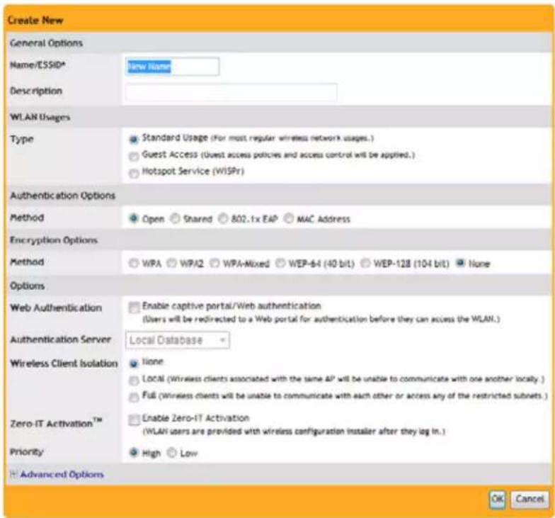
FIG. 21 Guest Pass Printout Customization - Create New
- Enter a Name (SSID) for this WLAN that will be easy for your guests to remember (e.g., "Guest WLAN"). The Description field is optional.
- Under Type, select Guest Access.
- Since this is a Guest network, the only Authentication Option available is Open.
- Choose an Encryption Method that provides the best compromise between security and compatibility, based on the kinds of client devices that you expect your guests will use.
- If you want your internal wireless traffic to have priority over guest traffic, set the Priority to Low.
- Click OK to save your changes.
Access Points
The Access Points page allows to configure and manage the individual access points accessible via the NXA-WAPZD1000.
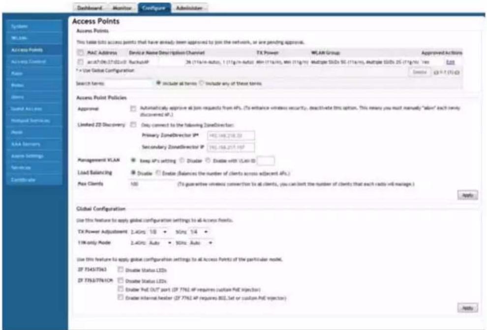
FIG. 22 Configure Tab - Access Points
| Configure Tab - Access Points | |
| Access Points: This section lists access points that have already been approved to join the network, or are pending approval. | |
| MAC Address: The MAC address of the AP. | |
| Device Name: The name or type of AP. | |
| Description: (Optional) A more detailed description of the AP. | |
| Channel: The channel being used by the AP to access the network. | |
| TX Power: The maximum and minimum broadcast power of the AP. | |
| WLAN Group: The individual WLAN group or groups to which the AP belongs. | |
| Approved: The notice as to whether or not this AP has been approved to access the network. | |
| Actions: | Click Edit to make changes to the AP configuration, and Allow to allow the AP onto the WLAN. |
| Access Point Policies: | |
| Approval: | Click this box to automatically approve all join requests from APs. |
| Limited ZD Discovery: Click this box to allow connection only to a preselected primary and secondary NXA-WAPZD1000. | |
| Management VLAN: Use these three options to select the AP's management VLAN. | |
| Load Balancing: | Click Enable to balance the number of clients across adjacent APs |
| Max Clients: | The maximum number of clients allowed access through the AP. |
| Global Configuration: | Use this feature to apply global configuration settings to all Access Points. |
Assigning a WLAN Group to an AP
To assign a WLAN group to an Access Point:
- Go to Configure > Access Points.
- In the list of access points, find the MAC address of the AP that you want to assign to a WLAN group, and then click Edit.
- In WLAN Group, select the WLAN group to which you want to assign the AP. You can only assign an AP to a single WLAN group.
- Click OK to save your changes.
Deploying NXA-WAPZD1000 WLANs in a VLAN Environment
You can set up an NXA-WAPZD1000 wireless LAN as an extension of a VLAN network environment by tagging wireless client and management traffic to specific VLANs. Qualifications include the following:
- Verifying that the VLAN switch supports native VLANs. A native VLAN is a VLAN that allows the user to designate untagged frames going in/out of a port to a specific VLAN. For example, if an 802.1Q port has VLANs 2, 3, and 4 assigned to it with VLAN 2 being the Native VLAN, frames on VLAN 2 that egress (exit) the port are not given an 802.1Q header (i.e., they are plain Ethernet frames). Frames which ingress (enter) this port and have no 802.1Q header are put into VLAN 2. Behavior of traffic relating to VLANs 3 and 4 is intuitive.
- Connecting the NXA-WAPZD1000 and any Access Points (APs) to VLAN trunk ports in the VLAN switch.
- Verifying that those trunk ports are on the same native VLAN.

All DNS, DHCP, ARP, and HTTP traffic from an unauthenticated wireless client will be passed onto the NXA-WAPZD1000 from the AP via the management VLAN. If the client belongs to a particular VLAN, the NXA-WAPZD1000 will add the corresponding VLAN tag before passing traffic to the corresponding wired network. After client authentication is performed, client traffic will directly go to the wired network from the AP, which will add the corresponding VLAN tag. This explains why it is necessary to configure tagged VLANs for all VLAN switch ports connecting to the NXA-WAPZD1000 and APs.
Tagging Management Traffic to a VLAN
Assigning management traffic to a specific management VLAN can provide benefits to the overall performance and security of a network. If your network is designed to segment management traffic to a specific VLAN, and you want to include the NXA-WAPZD1000's AP management traffic in this VLAN, you can set the parameters in the NXA-WAPZD1000 system configuration.

Assigning management traffic to a VLAN makes automatic AP provisioning more complicated, and should not be undertaken without a thorough understanding of your own network configuration as well as the wireless deployment. You must also configure any switches to pass VLAN traffic with the proper VLAN tags on the relevant physical ports.
To assign ZD - AP management traffic to a management VLAN:
- Go to Configure > System.
- In Device IP Settings, enter the VLAN ID in the VLAN field.
- If you are using an additional management interface for the NXA-WAPZD1000, enter the same ID in the VLAN field for the additional management interface.
- Click Apply to save your settings.
- Go to Configure > Access Points.
- In Access Point Policies, click the Enable with VLAN ID option next to Management VLAN, and enter the VLAN ID in the field provided.
- Click Apply to save your settings.


The NXA-WAPZD1000 will need to be rebooted after changing management VLAN settings.
- Go to Administer > Restart, and click Restart to reboot the NXA-WAPZD1000.
When configuring or updating the management VLAN settings, make sure that the same VLAN settings are applied on the Configure > Access Points > Access Point Policies > Management VLAN page, if APs exist on the same VLAN as the NXA-WAPZD1000.
How Dynamic VLAN Works
By default, all wireless clients associated with APs managed by the NXA-WAPZD1000 are segmented into a single VLAN (with VLAN ID 1). If you want to segment wireless clients into different VLANs (for example, for security purposes), you can enable dynamic VLAN.
Dynamic VLAN allows the NXA-WAPZD1000 to separate wireless clients into different network segments based on the VLAN ID that is assigned to each wireless user on the RADIUS server. As such, dynamic VLAN is implemented on a per-user basis.
Dynamic VLAN requirements:
● A RADIUS server must have already been added to the NXA-WAPZD1000
● WLAN authentication method must be set to 802.1X/EAP
● WLAN encryption method must be set to WPA or WPA2
How Dynamic VLAN works:
- User associates with a WLAN on which Dynamic VLAN has been enabled.
- The AP requires the user to authenticate with the RADIUS server via the NXA-WAPZD1000.
- When the user completes the authentication process, the NXA-WAPZD1000 sends the join approval for the user to the AP, along with the VLAN ID that has been assigned to the user on the RADIUS server.
- User joins the AP and is segmented to the VLAN ID that has been assigned to him.
For dynamic VLAN to work, you must configure the following RADIUS attributes for each user:
- Tunnel-Type: Set this attribute to VLAN.
- Tunnel-Medium-Type: Set this attribute to IEEE-802.
- Tunnel-Private-Group-ID: Set this attribute to the VLAN ID to which you want to segment this user.
Depending on your RADIUS setup, you may also need to include the user name or the MAC address of the wireless device that the user will be using to associate with the AP.
| RADIUS user attributes related to dynamic VLAN | ||
| Attribute Type ID Expected Value (Numerical) | ||
| Tunnel-Type 64 VLAN (13) | ||
| Tunnel-Media-Type 65 802 (6) | ||
| Tunnel-Private-Group-Id 81 VLAN ID | ||
Here is an example of the required attributes for three users as defined on Free RADIUS:
0018ded90ef3
User-Name = user1,
Tunnel-Type = VLAN,
Tunnel-Medium-Type = IEEE-802,
Tunnel-Private-Group-ID = 0014
00242b752ec4
User-Name = user2,
Tunnel-Type = VLAN,
Tunnel-Medium-Type = IEEE-802,
Tunnel-Private-Group-ID = 0012
013469acee5
User-Name = user3,
Tunnel-Type = VLAN,
Tunnel-Medium-Type = IEEE-802,
Tunnel-Private-Group-ID = 0012

NOTE
The values in bold are the users' MAC addresses.
Adding New Access Points to the WLAN
If your staffing or wireless coverage needs increase, you can add APs to your network easily and efficiently. Depending on your network security preferences, the new APs can be automatically detected and activated, or new APs may require per-device manual approval before becoming active.
The Automatic AP Approval process is enabled by default, automatically approving AP join requests. If you prefer, you can disable Automatic Approval. If this is your preference, the NXA-WAPZD1000 will detect new APs, alert you to their presence, and then wait for you to manually “approve” their activation.

NOTE
For Automatic AP Approval to work, the APs that you are adding must be on the same IP subnet or VLAN as the NXA-WAPZD1000.
Connecting the APs to the WLAN
- Place the new APs in the appropriate locations.
- Write down the MAC address (on the bottom of each device) and note the specific location of each AP as you distribute them.
- Connect the APs to the LAN with Ethernet cables.

NOTE
If using Gigabit Ethernet, ensure that you use Cat5e or better Ethernet cables.
- Connect each AP to a power source.

NOTE
If the APs that you are using are PoE-capable and power sources are not convenient, they will draw power through the Ethernet cabling if connected to a PoE-ready hub or switch.
Verifying/Approving New APs
- Go to Monitor > Access Points.
-
The Access Points page appears, showing the first 15 access points that have been approved or are awaiting approval. If the NXA-WAPZD1000 is managing more than 15 access points, the Show More button at the bottom of the page will be active. To display more access points in the list, click Show More. When all access points are displayed on the page, the Show More button disappears.
-
Review the Currently Managed APs table.
-
If the Configure > Access Points > Access Points Policies > Approval check box is checked, all new APs should be listed in the table, and their Status should be “Connected.”
-
If the Automatic AP Approval option is disabled, all new APs will be listed, but their status will be “Approval Pending.”
-
Under the Action column, click Allow. After the status is changed from "Disconnected" to "Connected," the new AP is activated and ready for use.

Use Monitoring > Map View to place the marker icons of any newly approved APs.
Reviewing Current Access Point Policies
The Access Point Policies options allow you to define how new APs are detected and approved for use in WLAN coverage, as well as policies on client distribution and communicating with the NXA-WAPZD1000. These policies are enforced on all APs managed by the NXA-WAPZD1000 unless a specific WLAN setting overrides them. For example, if you want to enable Load Balancing for most APs but disable it on specific WLANs, you would enable it in the Access Point Policies section, then disable it for the particular WLAN from the Configure > WLANs page.
To review and revise the general AP policies:
1. Go to Configure > Access Points.
-
Review the current settings in Access Point Policies. You can change the following settings:
-
Approval: This is enabled by default, which means that all join requests from any AP will be approved automatically. If you want to manually review and approve the joining of new APs to the WLAN, clear this check box.
- Limited ZD Discovery: If you have multiple NXA-WAPZD1000 devices on the network and want specific APs to join specific NXA-WAPZD1000s, you can limit NXA-WAPZD1000 discovery. To do this, select the Limited ZD Discovery check box, and then enter the IP addresses of the primary and secondary NXA-WAPZD1000 units to which you want APs to join.
When Limited ZD Discovery is enabled, APs will first attempt to join the primary NXA-WAPZD1000. If they cannot find or are unable to join the primary NXA-WAPZD1000, they will attempt to join the secondary device. If still unsuccessful, APs will stop attempting for a brief period of time, and then they will restart the joining process. They will repeat this process until they successfully join either the primary or secondary NXA-WAPZD1000.
If you have two NXA-WAPZD1000s in a Smart Redundancy configuration on your network, you can enter the primary and secondary ZD IP addresses here, or you can leave Limited ZD Discovery disabled. If the Limited ZD Discovery and Smart Redundancy information you enter is inconsistent, a warning message will be displayed asking you to confirm.

If you have two NXA-WAPZD1000s of the same model and license level, using the Smart Redundancy feature is recommended. If you have two devices of different license levels, you can use Limited ZD Discovery to provide limited redundancy; however, this method does not provide synchronization of the user database. For information on Smart Redundancy configuration, please refer to the Enabling Smart Redundancy section on page 17.
- Management VLAN: You can enable the NXA-WAPZD1000 management VLAN if you want to separate management traffic from regular network traffic. The following options are available:
Keep AP's setting: Click this option if you want to preserve the Management VLAN settings as configured on the AP. Note that Management VLAN on the AP is disabled by default.
Disable: Click this option if you want to disable the Management VLAN. If the Management VLAN is enabled on the AP, it will be disabled the next time the AP is provisioned by the NXA-WAPZD1000.
Enable with VLAN ID: If you want to enable the Management VLAN on all APs managed by this NXA-WAPZD1000, click this option, and then type the management VLAN ID (must be configured on the switch/router).

If you click Enable with VLAN ID, you also need to set the Management VLAN ID that the NXA-WAPZD1000 needs to use on the Configure > System Settings page. Otherwise, the NXA-WAPZD1000 and the APs will be unable to communicate via the Management VLAN.
- Load Balancing: Balances the number of clients across adjacent APs.
- Max Clients: If you want to guarantee wireless connections to all clients, you can limit the number of wireless clients that each AP (or radio, on dual radio APs) will manage.
In the Max Clients box, type the maximum number of clients per AP (default is 100). This is the maximum that any AP radio can accept. Because an AP/radio can provide service to multiple WLANs, you can also limit the number of clients that can associate to a WLAN, on a per AP/per radio basis.
3. Click Apply to save and apply your settings.
Applying Global Configuration Settings to APs
The following settings can be applied globally to all APs managed by the NXA-WAPZD1000:
- TX Power Adjustment: Allows you to manually set the transmit power on all 2.4GHz or 5GHz radios to Full, 1/2, 1/4, 1/8 or minimum (default is Auto).
- 11N Only Mode: Force all 802.11n APs to accept only 802.11n compliant devices on the 2.4GHz or 5GHz radio. If N-Only is selected, all older 802.11b/g devices will be denied access to the radio.
The following setting can be applied to all APs of a particular model managed by the NXA-WAPZD1000:
- Disable Status LEDs: When managed by the NXA-WAPZD1000, you can disable the LEDs for NXA-WAP1000 APs.
Global configuration settings can be superseded by individual AP settings. For example, if you want to set the transmit power to a lower setting for only a few specific APs, leave the TX Power Adjustment at Auto under Global Configuration, then go to the individual APs (via Configure > Access Points > Edit specific AP) and set the TX Power setting to a lower setting.
Managing Access Points Individually
You can add a description, or change the location, channelization, channel, or transmit power settings of a managed access point by editing the AP's parameters. Additionally, you can manually assign an IP address or disable WLAN service entirely for a specific radio (on dual radio APs).
To edit the parameters of an access point:
1. Go to Configure > Access Points.
-
Find the AP to edit in the Access Points table, and then click Edit under the Actions column.
-
Edit any of the following:
● Device Name: Give a name to the AP.
- Description: Enter a description for the AP. This description is used to identify the AP in the Map View.
- Location: Enter a recognizable location for the AP.
- GPS Coordinates: Enter GPS coordinates for location on Google Maps, if using FlexMaster.
- If the AP is a dual radio AP, the following parameters can be configured independently per radio:
Channelization: (For 802.11n only) The “channel width” determines the manner in which the spectrum is used during transmission.
- Channel: This is the channel used by the AP's network.
- TX Power: Specifies the maximum transmit power level relative to the calibrated power.
● WLAN Group: Specify a WLAN group for this radio. -
WLAN Service: Uncheck this check box to disable WLAN service entirely for this radio. (This option can be useful if you want 802.11n APs to provide service only on the 5.0 GHz radio, in order to reduce interference on the 2.4 GHz band, for example.) You can also disable service for a particular WLAN at specific times of day or days of the week, by setting the Service Schedule. For more information, please refer to the Advanced Options section on page 56.
-
If the AP is currently connected to the NXA-WAPZD1000, the Network Setting options appear. Use these options to configure the IP settings of the AP.
-
If you want the AP to keep its current IP address, click Keep AP's Setting. If the AP's IP address has not been set, it will automatically attempt to obtain an IP address via DHCP.
- If you want the AP to automatically obtain its IP address settings from a DHCP server on the network, click the DHCP option in Management IP. You do not need to configure the other settings (netmask, gateway, and DNS servers).
- If you want to assign a static IP address to the AP, click the Manual option in Management IP, and then set the values for the following options:
-
IP Address
-
Netmask
- Gateway
- Primary DNS Server
-
Secondary DNS Server
-
If Smart Mesh is enabled, the Advanced Options section lets you define the role this AP should play in the mesh network: Auto, Root AP, Mesh AP, or Disable (default is Auto). In most cases, leaving this setting on Auto to reduce the risk of isolating a Mesh AP is highly recommended. Select Disable if you do not want this AP to be part of your mesh network.
- If this AP is a Mesh AP and you want to manually set which APs can serve as its uplinks, select the Manual radio button under Advanced Options > Uplink Selection (default is Smart). The other APs in the mesh appear below the selection.
- Select the check box next to each AP that you want to allow the current AP to use as an uplink.
If you set Uplink Selection for an AP to Manual and the uplink AP that you selected is off or unavailable, the AP status on the Access Points page will appear as Isolated Mesh AP.
- Click OK to save your settings.
Optimizing Access Point Performance
The NXA-WAPZD1000, through the Browser-Based Configuration Pages, enables you to remotely monitor and adjust key hardware settings on each of your network APs. After assessing AP performance in the context of network performance, you can reset channels and adjust transmission power, or adjust the priority of certain WLANs over others, as needed.
Adjusting AP Settings
- Go to Configure > Access Points.
- Review the Access Points table and identify an AP that you want to adjust.
- Click the Edit button in that AP row.
-
Review and adjust any of the following Editing (AP) options:
-
MAC Address: This information is taken from the AP. It cannot be modified in the NXA-WAPZD1000.
- Description: Enter a short description of this device and its current location.
- Radio B/G Channel: Choose a specific channel for use by 802.11b/g devices from this drop-down list.
- TX Power: Choose the amount of power allocated to this channel. The default setting is “Auto” and your options range from “Full” to “Min.”

Some options are read-only depending on the approval status.
- Click OK. The adjusted AP will be automatically restarted, and when it is active, will be ready for network connections.

Load Balancing
Enabling load balancing can improve WLAN performance by helping to spread the client load between nearby access points, so that one AP does not get overloaded while another sits idle. The load balancing feature can be controlled from within the Browser-Based Configuration Pages to balance the number of clients per radio on adjacent APs. "Adjacent APs" are determined by the NXA-WAPZD1000 at startup by measuring the RSSI during channel scans. After startup, the NXA-WAPZD1000 uses subsequent scans to update the list of adjacent radios periodically and when a new AP sends its first scan report. When an AP leaves, the NXA-WAPZD1000 immediately updates the list of adjacent radios and refreshes the client limits at each affected AP.
Once the NXA-WAPZD1000 is aware of which APs are adjacent to each other, it begins managing the client load by sending desired client limits to the APs. These limits are “soft values” that can be exceeded in several scenarios, including: (1) when a client’s signal is so weak that it may not be able to support a link with another AP, and (2) when a client’s signal is so strong that it really belongs on this AP.
The APs maintain these desired client limits and enforce them once they reach the limits by withholding probe responses and authentication responses on any radio that has reached its limit.
Key points on load balancing:
- These rules apply only to client devices; the AP always responds to another AP that is attempting to set up or maintain a mesh network.
- Load balancing does not disassociate clients already connected.
- Load balancing takes action before a client association request, reducing the chance of client misbehavior.
- The process does not require any time-critical interaction between APs and the NXA-WAPZD1000.
- Provides control of adjacent AP distance with safeguards against abandoning clients.
- Can be disabled on a per-WLAN basis; for instance, in a voice WLAN, load balancing may not be desired due to voice roaming considerations.
● Background scanning must be enabled on the WLAN for load balancing to work.
To enable Load Balancing globally:
-
Go to Configure > Access Points.
-
In Access Point Policies, click the Enable button next to Load Balancing.
To disable Load Balancing on a per-WLAN basis:
- Go to Configure > WLANs.
- Click the Edit link beside the WLAN for which you want to disable load balancing.
- Click the Advanced Options link to expand the options.
- Click the Disable button next to Load Balancing.
Access Control
Access controls can be configured to control access to both your wireless network and to the Browser-Based Configuration Pages themselves. For network access, the NXA-WAPZD1000 features a block list as well as access control lists (ACL) to control access to the network.
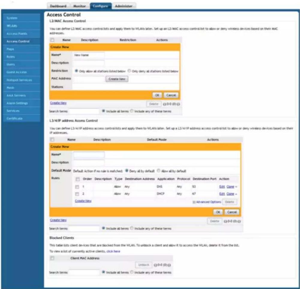
FIG. 23 Configure Tab - Access Control
| Configure Tab - Access Control | |
| L2/MAC Access Control: You can define L2/MAC access control lists and apply them to WLANs later. Set up an L2/MAC access control list to allow or deny wireless devices based on their MAC addresses. | |
| Name: The name of the L2/MAC access control list. | |
| Description: (Optional) A more detailed description of the L2/MAC access control list. | |
| Restriction: Notes on whether the list only allows or denies all stations listed. | |
| MAC Address: The MAC address of the device maintaining the access control list. | |
| Stations: | |
| L3/4/IP Address Access Control: You can define L3/4/IP address access control lists and apply them to WLANs later. Set up a L3/4/IP address access control list to allow or deny wireless devices based on their IP addresses. | |
| Name: The name of the L3/4/IP address access control list. | |
| Description: (Optional) A more detailed description of the access control list. | |
| Configure Tab - Access Control (Cont.) | |
| Default Mode: | Default Action if no rule is matched. Those rules are Deny all by default and Allow all by default. |
| Actions: | Click Edit to make changes to the access control list, and Clone to make an exact copy of the access control list. |
| Blocked Clients: | This table lists client devices that are blocked from the WLAN. |
| MAC Address: The MAC address | of the blocked client. |
WLAN ACLs and Block Lists
The NXA-WAPZD1000 provides two methods of controlling access to your wireless LA Ns:
- Block List: When users log into an NXA-WAPZD1000 network, their client devices (for example, laptop computers and handhelds) are recorded and tracked. If, for any reason, you need to block a client device from network use, you can do so via the Browser-Based Configuration Pages.
- Access Control Lists: Access control lists (ACLs) establish which devices are allowed to associate to a NXA-WAPZD1000-managed AP. By using the Configure > Access Control options, you can define Layer 2 ACLs (MAC address ACLs), which can then be applied to one or more NXA-WAPZD1000 WLANs. You can also create L3/L4 ACLs (to restrict access by IP address). ACLs are either allow-only or deny-only; that is, an ACL can be set up to allow only specified clients or to deny only specified clients.
Take note of the following NXA-WAPZD1000 rules:
- The block list is system-wide and is applied to all WLANs in addition to the per-WLAN ACL. If a MAC address is listed in the system-wide block list, it will be blocked even if it is an allowed entry in an ACL. Thus, the block list takes precedence over an ACL.
- MAC addresses that are in the deny list are blocked at the AP, not at the NXA-WAPZD1000.
Configuring Access Control Lists
You can build L2/MAC and L3/L4 access control lists to establish which devices are allowed to associate to the APs. You can configure these options on the Configure > Access Control page.
A system-wide block list is applied to all WLANs in addition to the per- WLAN ACL. The entries of the system-wide block list are added when the Admin chooses to block clients from the Monitor/Current Active Clients panel. The Admin can remove entries from the system-wide block list via Configure > Access Control > Block Clients list. If a MAC address is listed in the system-wide block list, it will be blocked even if it is an allowed entry in an ACL list.
L2/MAC Access Control
Using the Access Controls configuration options, you define Layer 2/MAC address ACLs, which can then be applied to one or more WLANs (upon WLAN creation or edit). ACLs are either allow-only or deny-only; that is, an ACL can be set up to allow only specified clients or to deny only specified clients. MAC addresses that are in the deny list are blocked at the AP, not at the NXA-WAPZD1000.
To configure an L2/MAC ACL:
- Go to Configure > Access Control.
- In L2/MAC Access Control, click Create New.
- Type a Name for the ACL.
- Type a Description of the ACL.
- Select the Restriction mode as either allow or deny.
- Type a MAC address in the MAC Address text box, and then click Create New to save the address. The new MAC address that you added appears next to the Stations field. You can enter up to 128 MAC addresses.
- Click OK to save the L2/MAC based ACL.
You can create up to 32 L2/MAC ACL rules, and each rule can contain up to 128 MAC addresses.

L3/L4 Access Control
In addition to L2/MAC based ACL, the NXA-WAPZD1000 also provides access control options at the Layer 3 and Layer 4 levels. This means that you can configure the access control options based on a set of criteria, including:
- Destination Address
- Application
- Protocol
- Destination Port
To create an L3/L4/IP address based ACL:
- Go to Configure > Access Control.
- In L3/4/IP address Access Control, click Create New.
- Type a Name for the ACL.
- Type a Description for the ACL.
- In Default Mode, set the default access privilege (allow all or deny all) that you want to grant all users by default.
- In Rules, click Create New or click Edit to edit an existing rule.
- Define each access policy by configuring a combination of the following:
- Type: The access privilege (allow or deny) that this policy grants.
- Destination Address: If you have a specific IP address to which you want to allow or deny access, type it here. Otherwise, select Any. (IP addresses must be in the format: A.B.C.D/M, where M is the bitmask).
- Application: If you have a specific application to which you want to allow or deny access, select it from the menu. Otherwise, select Any. If you select an option here besides Any, the Protocol and Destination Port options are disabled.
- Protocol: If you have a network protocol that you want to allow or deny, select it from the menu. Otherwise, click Any.
- Destination Port: If you have a specific destination port to which you want to allow or deny access, select it from the menu. Otherwise, select Any.
-
Repeat these steps to create up to 32 L3/L4/IP address-based access control rules.
-
Click OK to save the ACL.
NXA-WAPZD1000 Management ACL
The NXA-WAPZD1000 also includes an access control feature for controlling access to the Browser-Based Configuration Pages. The Management Access Control interface is located on the Configure > System screen. Options include limiting access by subnet, single IP address and IP address range.
Maps
If the NXA-WAPZD1000 does not display a floorplan for your worksite when you open the Monitor tab Map View (page 27), you can import a floorplan and place AP markers in relevant locations by following the steps outlined in this section. The sample floorplan image cannot be deleted, but it can be replaced with an actual floorplan image file and relabeled. Then you can add additional floorplan maps for additional locations or floors.
You can import an unlimited number of floorplan images to the NXA-WAPZD1000. However, the total file size of all imported floor maps is limited to 2MB. An error message appears when these file size limits are reached. Additionally, the maximum file size per floorplan image is 512Kb.
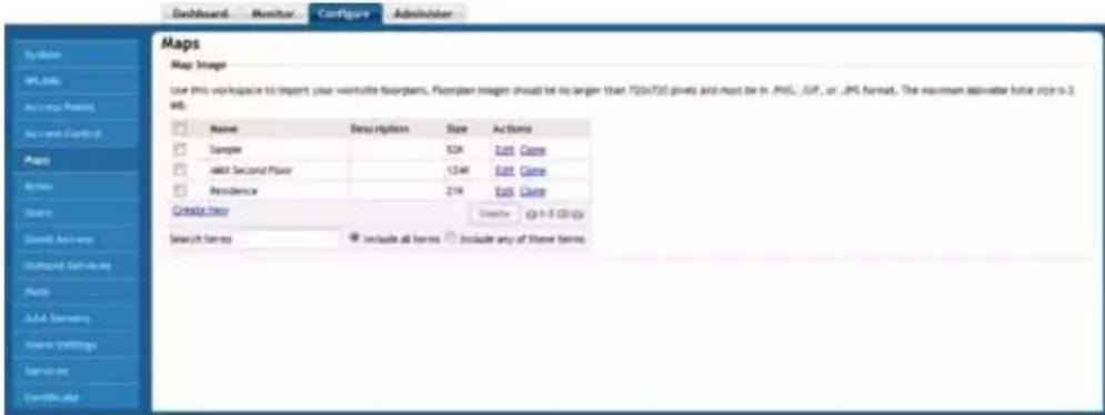
FIG. 24 Configure Tab - Maps
| Configure Tab - Maps | |
| Name: The name of the map file. | |
| Description: (Optional) A more detailed description of the map file. | |
| Size: The size of the map in kilobytes. | |
| Actions: | Click Edit to modify the map file and Clone to make an exact copy of it. |
Importing a Floorplan Image
- Go to Configure > Maps.
- Click Create New. The Create New form appears.
- In Name, type a name to assign to the floorplan image that you will be importing. Type a description as well, if preferred.
- Click Browse. The Choose File dialog box appears.
-
Browse to the location of the floorplan image file, select the file, and then click Open to import it. If the import is successful, a thumbnail version of the floorplan will appear in the Current Image area.
-
Go to Monitor > Map View (page 27) to see this image.
You can now use the Map View to place the Access Point markers.
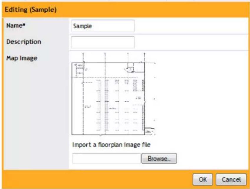
FIG. 25 Maps - Editing
Roles and Policies
The NXA-WAPZD1000 provides a "Default" role that is automatically applied to all new user accounts. This role links all users to the internal WLAN and permits access to all WLANs by default. As an alternative, you can create additional roles that you can assign to selected wireless network users, to limit their access to certain WLANs, to allow them to log in with non-standard client devices, or to grant permission to generate guest passes. (You can then edit the "default" role to disable the guest pass generation option.)
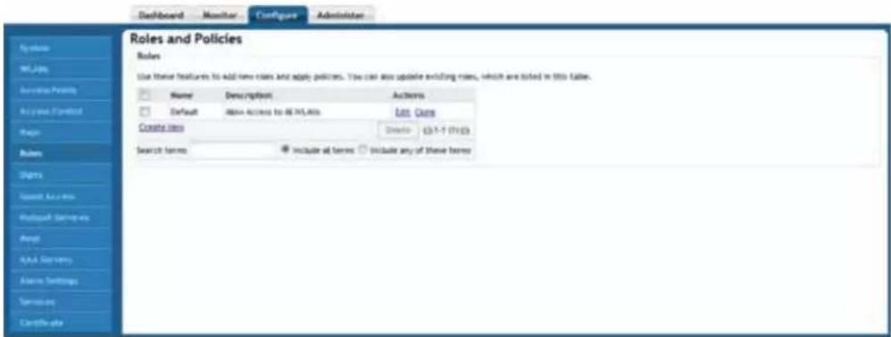
FIG. 26 Configure Tab - Roles and Policies
| Configure Tab - Roles and Policies | |
| Name: The name of the role. | |
| Description: (Optional) A more detailed description of the role. | |
| Actions: | Click Edit to make modifications to the selected role, and Clone to make an exact copy of it. |
Creating New User Roles
To create new user roles:
- Go to Configure > Roles. The Roles and Policies page appears, displaying a Default role in the Roles table.
- Click Create New (below the Roles table).
- Type a Name and a short Description for this role.
-
Choose the options for this role from the following:
-
Group Attributes: Fill in this field only if you are creating a user role with administrator privileges and you are using Active Directory or LDAP as the authentication server. Enter the User Group name here. Active Directory/LDAP users with the same group attributes are automatically mapped to this user role.
- Allow All WLANs: You have two options: (1) Allow Access to all WLANs, or (2) Specify WLAN Access. If you select the second option, you must specify the WLANs by clicking the check box next to each one. This option requires that you create WLANs prior to setting this policy (see Creating a New WLAN).
- Guest Pass: If you want users with this role to have permission to generate guest passes, activate this option.

When creating a guest pass generator Role, you must ensure that this Role is given access to the Guest WLAN. If you create a Role and allow guest pass generation, but do not allow the Role access the relevant WLAN, members of the "Guest Pass Generator" Role will still be unable to generate guest passes for the Guest WLAN.
- Administration: This option allows you to create a user role with NXA-WAPZD1000 administration privileges - either full access or limited (read only) access.
-
When you are finished, click OK to save the entries. This role is ready for assignment to authorized users.
-
If you want to create additional roles with different policies, repeat this procedure.
Controlling Guest Pass Generation Privileges
To disable the guest pass generation privilege granted to all basic "default" role users:
- Go to Configure > Roles.
- When the Roles and Policies page appears, a table lists all existing roles, including Default. Click Edit (in the Default role row) to open the Editing window (FIG. 27).
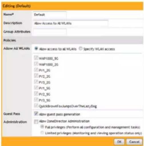
FIG. 27 Roles - Editing
| Roles - Editing | |
| Name: Enter a name for this role. | |
| Description: Enter a description for | this role |
| Group Attributes: Fill in this field only if you are creating a user role based on Group attributes extracted from an Active Directory or LDAP server (for more information, please refer to the Group Extraction section on page 99).Enter the User Group name here. Active Directory/LDAP users with the same group attributes are automatically mapped to this user role. | |
| Policies: | |
| Allow All WLANs: You have two options: (1) Allow Access to all WLANs, or (2) SpecifyWLAN Access. If you select the second option, you must specify the WLANs by clicking the check box next to each one. This option requires that you create WLANs prior to setting this policy. For more information, please refer to the Creating a WLAN section on page 53. | |
| Guest Pass: If you want users with this role to have the permission to generate guest passes, enable this option. | |
| Administration: This option allows you to create a user role with NXA-WAPZD1000administration privileges - either full access or limited (read only) access. | |
- In the Policies options, clear the Allow Guest Pass Generation check box.
- Click OK to save your settings. Users with "default" roles no longer have guest pass generation privileges.
When creating a guest pass generator Role, you must ensure that this Role is given access to the Guest WLAN. If you create a Role and allow guest pass generation, but do not allow the Role access the relevant WLAN, members of the "Guest Pass Generator" Role will still be unable to generate guest passes for the Guest WLAN.

- When you finish, click OK to save your settings. This role is ready for assignment to authorized users. If you want to create additional roles with different policies, repeat this procedure.
Creating a Guest Pass Generation User Role
To create a guest pass generator role that can be assigned to authorized users:
- Go to Configure >Roles.
- In the Roles table, click Create New.
-
When the Create New features appear, make these entries:
-
Name: Enter a name for this role (e.g., "Guest Pass Generator").
- Description: Enter a short description of this role's application.
- Group Attributes: This field is only available if you choose Active Directory as your authentication server. Enter the Active Directory User Group names here. Active Directory users with the same group attributes are automatically mapped to this user role.
- Allow All WLANs: You have two options: (1) allow all users with this role to connect to all WLANs, or (2) limit this role's users to specific WLANs, and then pick the WLANs to which they can connect.

NOTE
When creating a guest pass generator Role, you must ensure that this Role is given access to the Guest WLAN. If you create a Role and allow guest pass generation, but do not allow the Role access the relevant WLAN, members of the "Guest Pass Generator" Role will still be unable to generate guest passes for the Guest WLAN.
- Guest Pass: If you want users with this role to have permission to generate guest passes, check this option.
- Click OK to save your settings. This new role is ready for application to authorized users.
Users
Once your wireless network is set up, you can instruct the NXA-WAPZD1000 to authenticate wireless users by referring to accounts that are stored in the NXA-WAPZD1000's internal user database.
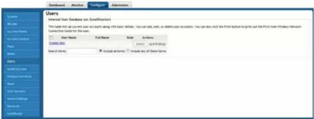
FIG. 28 Configure Tab - Users
| Configure Tab - Users | |
| User Name: The name of the particular user. | |
| Full Name: The full name of the particular user. | |
| Role: The role assigned to the user. | |
| Actions: | Click Edit to make modifications to the selected user, and Clone to make an exact copy of it. |
Internal User Database
To use the internal user database as the default authentication source and to create new user accounts in the database:
- Go to Configure > Users.
- In the Internal User Database table, click Create New.
- When the Create New form appears (FIG. 29), fill in the text fields with the appropriate entries:
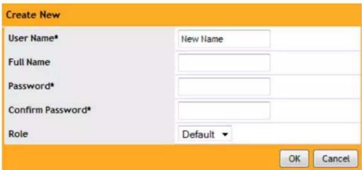
FIG. 29 Users - Create New
| Users - Create New | |
| User Name*: Enter a name for this | user, up to 32 characters in length, using letters, numbers and the period (.) character. User names are case-sensitive. |
| Full Name: Enter the assigned user | 's first and last name. |
| Password*: Enter a unique password for this user, using a combination of letters and numbers, between 4 and 32 characters in length. Do not incorporate any letter spaces. Passwords are case-sensitive. | |
| Confirm Password*: Re-enter the same password for this user. | |
| Role: The default is "Default". | |

The NXA-WAPZD1000 can support up to 1,250 combined total users and guest passes in the internal database.
- If you have created roles that enable non-standard client logins or that gather staff members into workgroups (in the Roles and Policies section on page 79), open the Role menu, and then choose the appropriate role for this user.
- Click OK to save your settings. Be sure to communicate the user name and password to the appropriate end user.
Managing Current User Accounts
The NXA-WAPZD1000 allows you to review your current user roster on the internal user database and to make changes to existing user accounts as needed.
To change an existing user account:
- Go to Configure > Users.
- Locate the specific user account in the Internal User Database panel, and then click Edit.
- When the Editing [user name] form appears, make the needed changes.
- If a role must be replaced, open that menu and choose a new role for this user.
- Click OK to save your settings. Be sure to communicate the relevant changes to the appropriate end user. To delete a user record:
-
Go to Configure > Users.
-
When the Users screen appears, review the "Internal Users Database."
- To delete one or more records, click the check boxes next to those account records.
- Click the now-active Delete button.
- When the Deletion Confirmation dialog box appears, click OK to save your settings. The records are removed from the internal users database.
Assigning a Pass Generator Role to a User Account
To assign a guest pass generator role to a user account:
- Go to Configure > User.
- At the bottom of the Internal Users Database, click Create New.
- When the Create New form appears, fill in the text fields with the appropriate entries.
- Open the Role menu and choose the assigned role for this user.

NOTE
You can edit an existing user account and reassign the pass generator role, if you prefer.
- Click OK to save your settings. Be sure to communicate the role, user name and password to the appropriate end user.
Guest Access
By default, all of your users are allowed to issue temporary “day use” guest passes for visitors and contractors. Such a guest pass allows its user to connect to the WLAN. You must decide whether or not to permit all-orsome users to generate guest passes. Additionally, you may also want to review the default settings and policies that control guest use of the network. These include options you can fine-tune to fit your work environment.

FIG. 30 Configure Tab - Guest Access
| Configure Tab - Guest Access | |
| Enable Guest Access: | Use these features to set limits for guest pass access to your wireless network. |
| Authentication: Select the level of authorization to be given to the guest. | |
| Terms of Use: Click the box to show the terms of use to the guest. | |
| Redirection: Select the URL to be viewed by the guest after accepting the terms of use. | |
| Guest Pass Generation: Authenticated users can generate guest passes at the URL shown below. | |
| Guest Pass Generation URL: The URL of the guest pass generator. | |
| Authentication Server: The authentication server being used. | |
| Validity Period: Select the length of time the guest pass will remain valid. | |
| Restricted Subnet Access: | Guest users are automatically blocked from the subnets to which the NXA-WAPZD1000 and its managed APs are connected. If there are other subnets on which you want to block or allow guest users, you can create and configure up to 22 guest access rules below. Note that guest access rules are prioritized in the order that they are listed (1 has highest priority). |
| Web Portal Logo: Upload a logo to show it on the Web portal pages. | |
| Guest Access Customization: Use this feature to customize the guest user login page. | |
| Guest Pass Printout Customization: | Use this workspace to import your custom Guest Pass Printout in HTML format. |

NOTE
The NXA-WAPZD1000 can support up to 1,250 combined total users and guest passes in the internal database.
Configuring System-Wide Guest Access Policy
The Enable Guest Access options enable the administrator to define the system-wide guest access policy. You can require guests to validate their guest pass, accept terms of use, and be redirected to a URL you specify.
1. Go to Configure > Guest Access.
-
Under Enable Guest Access, select the Authentication type to use:
-
Use guest pass authentication: Redirect the user to a page requiring a valid guest pass before allowing the user to use the guest WLAN.
- If you want multiple guests to be able to use the same guest pass simultaneously, select the Allow multiple users to share a single guest pass check box.
-
No authentication: Do not require redirection and guest pass validation.
-
Under Terms of Use, select the Show terms of use check box to require the guest user to read and accept your terms of use prior to use. Type (or cut and paste) your terms of use into the large text box.
- Under Redirection, select one of the following radio buttons to use/not use redirection:
- Redirect to the URL that the user intends to visit: Allows the guest user to continue to their destination without redirection.
- Redirect to the following URL: Redirect the user to a specified Web page (entered into the text box) prior to forwarding them to their destination. When guest users land on this page, they are shown the expiration time for their guest pass.
- Click Apply to save your settings.
Working with Guest Passes
Guest passes are temporary privileges granted to guests to access your wireless LANs. The NXA-WAPZD1000 provides many options for customizing guest passes, controlling who is allowed to issue guest passes, and controlling the scope of access to be granted.
Activating Guest Pass Generation
To grant authenticated users the privilege to generate guest passes:
- Go to Configure > Guest Access.
- Scroll down to the Guest Pass Generation section.
- In Authentication Server, select the authentication server that you want to use to authenticate users who want to generate guest passes.
- If you configured an AAA server (RADIUS, Active Directory or LDAP) on the Configure > AAA Servers page and you want to use that server to authenticate users, select the server name from the drop-down menu. (For more information, please refer to the Using an External Server for User Authentication section on page 97).

NOTE
Although you can use an external AAA server for authentication, you can not use an AAA server for accounting on a guest WLAN. AAA accounting is only supported on 802.1X EAP WLANs.
- If you want to use the NXA-WAPZD1000's internal database, select Local Database.
- Set the guest pass validity period by selecting one of the following options:
- Effective from the creation time: This type of guest pass is valid from the time it is first created to the specified expiration time, even if it is not being used by any end user.
- Effective from first use: This type of guest pass is valid from the time the user uses it to authenticate with the NXA-WAPZD1000 until the specified expiration time. An additional parameter (A Guest Pass will expire in X days) can be configured to specify when an unused guest pass will expire regardless of use. The default is 7 days.
- When you finish, click Apply to save your settings and make this new policy active.

NOTE
Remember to inform users that they can access the Guest Pass Generation page at https://{NXA-WAPZD1000-hostname-or-ipaddress}/guestpass.
Generating and Printing a Single Guest Pass
You can provide the following instructions to users with guest pass generation privileges. A single guest pass can be used for one-time login, time-limited multiple logins for a single guest user, or can be configured so that a single guest pass can be shared by multiple users.

NOTE
The following procedure will guide you through generating and printing an individual guest pass.

NOTE
Before starting, make sure that your computer is connected to a local or network printer.
To generate a single guest pass:
- On your computer, start your Web browser.
- In the address or location bar, type the URL of the NXA-WAPZD1000 Guest Pass Generation page: https://{NXA-WAPZD1000-hostname-or-ipaddress}/guestpass
-
In User Name, type your user name.
-
In Password, type your password.
- Click Log In. The Guest Information page appears. On this page, you need to provide information about the guest user to enable the NXA-WAPZD1000 to generate the guest pass.
-
On the Guest Information page, fill in the following options:
-
Creation Type: Choose Single to generate a single guest pass.
● Full Name: Type the name of the guest user for whom you are generating the guest pass. - Valid for: Specify the time period when the guest pass will be valid. Do this by typing a number in the blank box, and then selecting a time unit (Days, Hours, or Weeks).
- WLAN: Select the WLAN for this guest (typically, a "guest" WLAN).
- Key: Leave as is if you want to use the random key that the NXA-WAPZD1000 generated. If you want to use a key that is easy to remember, delete the random key, and then type a custom key. For example, if the NXA-WAPZD1000 generated the random key OVEGS-RZKKF, you can change it to joe-guest-key. Customized keys must be between one and 16 ASCII characters.
- Remarks (optional): Type any notes or comments. For example, if the guest user is a visitor from a partner organization, you can type the name of the organization.
- Sharable: Check this box to allow multiple users to share a single guest pass. (This option will only be available if you allowed multiple users to share a single guest pass on the Configure > Guest Access page.)
-
Session: Enable this check box and select a time increment after which guests will be required to log in again. If this feature is disabled, connected users will not be required to re-log in until the guest pass expires.
-
Click Next. The Guest Pass Generated page appears.
- In the drop-down menu, select the guest pass instructions that you want to print out. If you did not create custom guest pass printouts, select Default.
- Click Print Instructions. A new browser page appears and displays the guest pass instructions. At the same time, the Print dialog box appears.
- Select the printer that you want to use, and then click OK to print the guest pass instructions.
You have completed generating and printing a guest pass for your guest user.
Generating and Printing Multiple Guest Passes at Once
You can provide the following instructions to users with guest pass generation privileges.

Before starting, make sure that your computer is connected to a local or network printer.
To generate and print multiple guest passes at the same time:
- On your computer, start your Web browser.
- In the address or location bar, type the URL of the NXA-WAPZD1000 Guest Pass Generation page: https://{zonedirector-hostname-or-ipaddress}/guestpass
- In User Name, type your user name.
- In Password, type your password.
- Click Log In. The Guest Information page appears. On this page, you need to provide information about the guest users to enable the NXA-WAPZD1000 to generate the guest passes.
-
On the Guest Information page, fill in the following options:
-
Creation Type: Click Multiple.
- Valid for: Specify the time period during which the guest passes will be valid. Do this by typing a number in the blank box, and then selecting a time unit (Days, Hours, or Weeks).
- WLAN: Select one of the existing WLANs with which the guest users will be allowed to associate.
-
Number: Select the number of guest passes that you want to generate. The NXA-WAPZD1000 will automatically populate the names of each user (Batch-Guest-1, Batch-Guest-2, and so on) to generate the guest passes.
-
Profile (*.csv): If you have created a Guest Pass Profile, use this option to import the file.
- Sharable: Select this option if you want to allow multiple users to share a single guest pass. (This option will only be available if you allowed multiple users to share a single guest pass on the Configure > Guest Access page.)
-
Session: Enable this check box and select a time increment after which guests will be required to log in again. If this feature is disabled, connected users will not be required to re-log in until the guest pass expires. If you want to be able to identify the guest pass users by their names (for monitoring or auditing purposes in a hotel setting, for example), click Choose File, and upload a guest pass profile instead.
-
Click Next. The Guest Pass Generated page appears, displaying the guest pass user names and expiration dates.
- In Select a template for Guest Pass instructions, select the guest pass instructions that you want to print out. If you did not create custom guest pass printouts, select Default.
- Print the instructions for a single guest pass or print all of them.
- To print instructions for all guest passes, click Print All Instructions.
- To print instructions for a single guest pass, click the Print link that is in the same row as the guest pass for which you want to print instructions.
A new browser page appears and displays the guest pass instructions. At the same time, the Print dialog box appears.
- Select the printer that you want to use, and then click OK to print the guest pass instructions.
You have completed generating and printing guest passes for your guest users. If you want to save a record of the batch guest passes that you have generated, click the here link in "Click here to download the generated Guest Passes record," and then download and save the CSV file to your computer.
Creating a Guest Pass Profile
To create a guest pass profile:
- Log in to the guest pass generation page. Refer to steps 2 to 5 in the Generating and Printing Multiple Guest Passes at Once section on page 88 for instructions.
- In Creation Type, click Multiple.
- Click the click here link in To download a profile sample, click here.
- Save the sample guest pass profile (in CSV format) to your computer.
-
Using a spreadsheet application, open the CSV file and edit the guest pass profile by filling out the following columns:
-
Guest Name: Type the name of the guest user (one name per row).
- Remarks: (Optional) Type any note or remarks about the guest pass.
-
Key: Type a guest pass key consisting of 1-16 alphanumeric characters. If you want the NXA-WAPZD1000 to generate the guest pass key automatically, leave this column blank.
-
Go back to the Guest Information page, and then complete steps 6 to 10 in the Generating and Printing Multiple Guest Passes at Once section on page 88 to upload the guest pass profile and generate multiple guest passes.
Monitoring Generated Guest Passes
Once you have generated a pass for a guest, you can monitor and, if necessary, remove it.
- Go to Monitor > Generated Guest Passes.
- View generated guest passes.
- To remove a guest pass, select the check box for the guest pass.
- Click the Delete button.
Configuring Guest Subnet Access
By default, guest pass users are automatically blocked from the NXA-WAPZD1000 subnet (format: A.B.C.D/M) and the subnet of the AP to which the guest user is connected. If you want to create additional rules that allow or restrict guest users from specific subnets, use the Guest Access > Restricted Subnet Access section.
You can create up to 22 subnet access rules, which will be enforced both on the NXA-WAPZD1000 side (for tunneled/redirect traffic) and the AP side (for local-bridging traffic).

All guests share this same subnet access policy.
To create a guest access rule for a subnet:
- Go to Configure > Guest Access.
- In the Restricted Subnet Access section, click Create New. Text boxes appear under the table columns in which you can enter parameters that define the access rule.
- Under Description, type a name or description for the access rule that you are creating.
- Under Type, select Deny if this rule will prevent guest users from accessing certain subnets, or select Allow if this rule will allow them access.
- Under Destination Address, type the IP address and subnet mask (format: A.B.C.D/M) on which you want to allow or deny users access.
- If you want to allow or restrict subnet access based on the application, protocol, or destination port used, click the Advanced Options link, and then configure the settings.
- Click OK to save the subnet access rule.
Repeat Steps 2 to 7 to create up to 22 subnet access rules.
Customizing the Guest Login Page
You can customize the guest user login page, to display your corporate logo and to note helpful instructions, along with a "Welcome" title.
If you want to include a logo, you will need to prepare a Web-ready graphic file, in one of three acceptable formats (.JPG, .GIF or .PNG). Make sure that the logo file does not exceed the following:
• Length: Two inches on any side
- File size: 20KB
To customize the guest login page:
- Go to Configure > Guest Access.
- Scroll down to the Web Portal Logo section.
- If your logo is ready for use, click Browse to open a dialog box that you can use to import the logo file. (The NXA-WAPZD1000 will notify you if the file is too large.height or width).
- Scroll down to the Guest Access Customization section.
- (Optional) Delete the text in the Title field and type a short descriptive title or "welcome" message.
- Click Apply to save your settings. A Setting applied! confirmation message briefly appears.
Creating a Custom Guest Pass Printout
The guest pass printout is a printable HTML page that contains instructions for the guest pass user on how to connect to the wireless network successfully. The authenticated user who is generating the guest pass will need to print out this HTML page and provide it to the guest pass user. A guest pass in English is included by default.
As administrator, you can create custom guest pass printouts. For example, if your organization receives visitors who speak different languages, you can create guest pass printouts in other languages.
To create a custom guest pass printout:
- Go to Configure > Guest Access.
-
Scroll down to the Guest Pass Printout Customization section (bottom of the page).
-
Click the click here link under the Guest Pass Printout Customization section title to download the sample guest pass printout (in HTML format). Save the HTML file to your computer.
-
Using a text or HTML editor, customize the guest pass printout. Note that only ASCII characters can be used. You can do any or all of the following:
-
Reword the instructions
● Translate the instructions to another language - Customize the HTML formatting
The guest pass printout contains several tokens or variables that are substituted with actual data when the guest pass is generated. When you customize the guest pass printout, make sure that these tokens are not deleted.
- Go back to the Guest Pass Printout Customization section, and then click Create New. The Create New form appears.
- In Name, type a name for the guest pass printout that you are creating. For example, if this guest pass printout is in Spanish, you can type Spanish.
- In Description (optional), add a brief description of the guest pass printout.
- Click Browse, select the HTML file that you customized earlier, and then click Open. The NXA-WAPZD1000 copies the HTML file to its database.
- Click Import to save the HTML file to the NXA-WAPZD1000 database.
You have completed creating a custom guest pass printout. When users generate a guest pass, the custom printout that you created will appear as one of the options that they can print.
Guest Pass Printout Tokens
The following table lists the tokens that are used in the guest pass printout. Make sure that they are not accidentally deleted when you customize the guest pass printout.
| Guest Pass Printout Tokens | |
| Token: Description: | |
| {GP_GUEST_NAME} Guest pass user name | |
| {GP_GUEST_KEY} Guest pass key | |
| {GP_IF_EFFECTIVE_FROM_CREATION_TIME} | If you set the validity period of guest passes toEffective from the creation time in the Guest Pass Generation section, this token shows when the guest pass was created and when it will expire. |
| {GP_ELSEIF_EFFECTIVE_FROM_FIRST_USE} | If you set the validity period of guest passes toEffective from first use in the Guest Pass Generation section, this token shows the number of days during which the guest pass will be valid after activation. It also shows the date and time when the guest pass will expire if not activated. |
| {GP_ENDIF_EFFECTIVE} This token is used in conjunction with either the{GP_ELSEIF_EFFECTIVE_FROM_FIRST_USE} or{GP_ENDIF_EFFECTIVE} token. | |
| {GP_VALID_DAYS} Number of days for which the guest pass is valid. | |
| {GP_VALID_TIME} Date and time when the guest pass expires. | |
| {GP_GUEST_WLAN} Name of WLAN that the guest user can access. | |
Hotspot Services
A hotspot is a venue or area that provides wireless Internet access to devices with wireless networking capability, such laptops, PDAs, and other portable devices. Hotspots are usually available in public venues such as hotels, airports, restaurants, and shopping malls.
The NXA-WAPZD1000 has a built-in hotspot feature that you can enable and configure to provide hotspot service to users via its WLANs. In addition to the NXA-WAPZD1000 and its managed APs, you will need the following to deploy a hotspot:
- Captive Portal: A special Web page, typically a logon page, to which users that have associated with your hotspot will be redirected for authentication purposes. Users will need to enter a valid user name and password before they are allowed access to the Internet through the hotspot. Open source captive portal packages, such as Chillispot, are available on the Internet.
- RADIUS Server: A Remote Authentication Dial-In User Service (RADIUS) through which users can authenticate.
For installation and configuration instructions for the captive portal and RADIUS server software, refer to the documentation that was provided with them.
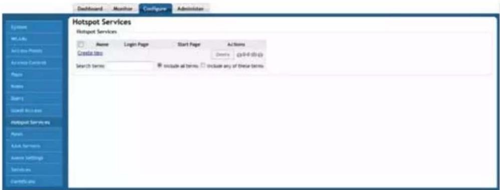
FIG. 31 Hotspot Services
| Configure Tab - Hotspot Services | |
| Name: The name of the hotspot. | |
| Login Page: The URL of the page | where hotspot users can log in to access the service. |
| Start Page: The page where users | will be redirected after logging in successfully |
| Actions: The particular restrictions | on access to this hotspot. |
Creating a Hotspot Service
Create a hotspot service configuration that you can deploy to WLANs that you want to provide hotspot service. After completing the steps below, you will need to set the WLANs that you want to provide hotspot service.
To create a hotspot service:
1. Go to Configure > Hotspot Services.
- Click Create New. The Create New form appears (FIG. 32).

FIG. 32 Hotspot Services - Create New
-
In Login Page (under Redirection), type the URL of the captive portal (the page where hotspot users can log in to access the service).
-
Configure optional settings as preferred:
-
In Start Page, configure where users will be redirected after logging in successfully. You could redirect them to the page that they want to visit, or you could set a different page where users will be redirected (for example, your company Web site).
-
In Session Timeout, select the check box, and then set a maximum session time (in minutes) after which sessions will be restarted automatically.
-
In Idle Timeout, select the check box, and then set a maximum idle time (in minutes) after which idle users will be logged out automatically.
- In Authentication Server, select the AAA server that you want to use to authenticate users.
- In Accounting Server (if you have an accounting server setup), configure the frequency (in minutes) at which accounting data will be retrieved.
- In Walled Garden, type network destinations (URL or IP address) that users can access without going through authentication. A Walled Garden is a limited environment to which an unauthenticated user is given access for the purpose of setting up an account. After the account is established, the user is allowed out of the Walled Garden. URLs will be resolved to an IP address (up to four). Users will not be able to click through to other URLs that may be presented on a page if that page is hosted on a server with a different IP address. Avoid using common URLs that are translated into many IP addresses (such as www.yahoo.com), as users may be redirected to reauthenticate when they navigate through the page.
- In Restricted Subnet, type the subnets to which hotspot users will be prevented from accessing.
5. Click OK to save the hotspot settings.
The page refreshes and the hotspot service you created appears in the list. You may now assign the WLANs that you want to provide hotspot service.
Mesh
Enabling Mesh capability on the Mesh page allows you to deploy your access points without using wires to connect them.
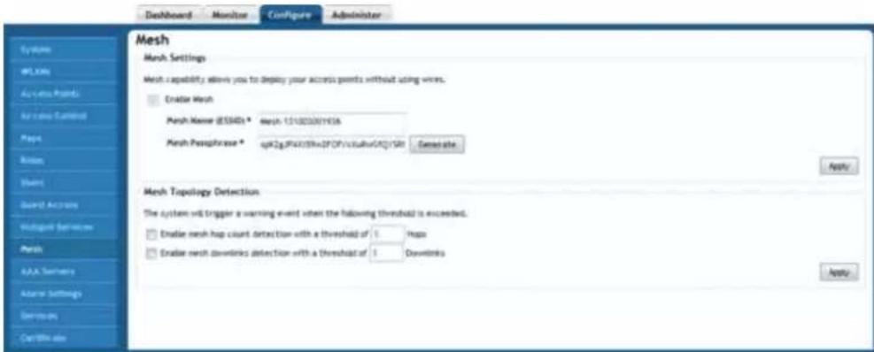
FIG. 33 Configure Tab - Mesh
| Configure Tab - Mesh | |
| Mesh Settings: This section allows | enabling and detailing of mesh settings. |
| Mesh Name (ESSID): The name | of the mesh network. |
| Mesh Passphrase: | A passphrase that contains at least 12 characters. This passphrase will be used by the NXA-WAPZD1000 to secure the traffic between Mesh APs. |
Enabling Mesh Capability
To enable mesh capability:
- Go to Configure > Mesh.
- Under Mesh Settings, select the Enable Mesh check box.
You can not disable Smart Mesh once you enable it. This is by design, to prevent isolating nodes. If you want to disable Smart Mesh once it has been enabled, you will have to factory reset the NXA-WAPZD1000, or disable mesh for each AP, as described in the Managing Access Points Individually section on page 71.
- In Mesh Name (ESSID), type a name for the mesh network. Alternatively, do nothing to accept the default mesh name that the NXA-WAPZD1000 has generated.
- In Mesh Passphrase, type a passphrase that contains at least 12 characters. This passphrase will be used by the NXA-WAPZD1000 to secure the traffic between Mesh APs. Alternatively, click Generate to generate a random passphrase with 32 characters or more.
- In the Mesh Topology Detection section, set the number of mesh hops and mesh downlinks after which the NXA-WAPZD1000 should trigger warning messages. Then click Apply in the same section.
- In the Mesh Settings section, click Apply to save your settings and enable Smart Mesh.
You have completed enabling mesh capability on the NXA-WAPZD1000. You can now start provisioning and deploying the APs that you want to be part of your wireless mesh network.

Authentication/Accounting Servers
Once your wireless network is set up, you can instruct the NXA-WAPZD1000 to authenticate wireless users using your existing Authentication, Authorization and Accounting (AAA) server. The following types of AAA servers are supported:
• Active Directory
- LDAP
• RADIUS / RADIUS Accounting
The Browser-Based Configuration Pages provides a sample template for each of the AAA server types. These templates can be customized to match your specific network setup, or you can create new AAA server objects and add them to the list.
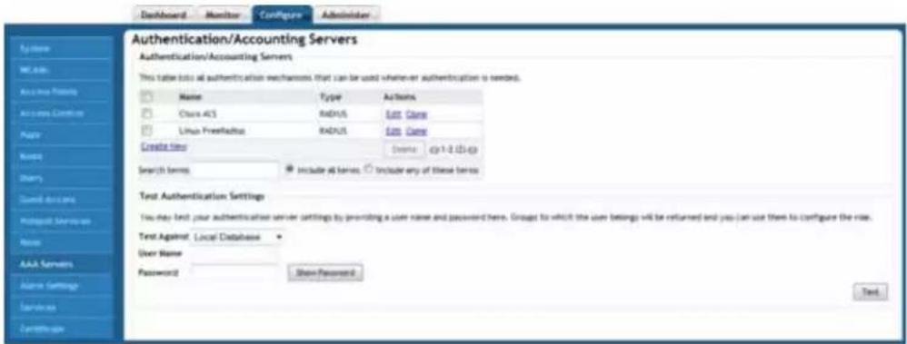
FIG. 34 Configure Tab - Authentication/Accounting Servers
| Configure Tab - Authentication/Accounting Servers | |
| Authentication/Accounting Servers: | |
| Name: The name of the authentication/accounting server being used. | |
| Type: The type of server being used. | |
| Actions: | Click Edit to change settings on this entry and Clone to make an exact copy of it. |
| Test Authentication Settings: | |
| Test Against: | Select Local Database, Cisco ACS, or Linux FreeRadius. |
| User Name: The username being tested. | |
| Passwords: The password being tested. | |
Using an External AAA Server
If you want to authenticate users against an external Authentication, Authorization and Accounting (AAA) server, you will need to first configure your AAA server, then point the NXA-WAPZD1000 to the AAA server, so that requests will be passed through the NXA-WAPZD1000 before access is granted. This section describes the tasks that you need to perform on the NXA-WAPZD1000 to ensure the device can communicate with your AAA server.

For specific instructions on AAA server configuration, refer to the documentation that is supplied with your authentication server.
The NXA-WAPZD1000 supports three types of AAA server:
• Active Directory
- LDAP
• RADIUS / RADIUS Accounting
Using an External Server for User Authentication
To use an external authentication server:
- Go to Configure > AAA Servers.
- Click the Create New link in the Authentication/Accounting Servers table, or click Edit next to the relevant server type in the list.
- When the Create New form (or "Editing" form) appears, make the following entries:
- In Name, type a descriptive name for this authentication server (for example, "Active Directory").
- In Type, verify that one of the following options is selected:
- Active Directory: If you select this option, you also need to enter the IP address of the AD server, its port number (default is 389), and its Windows Domain Name.
- LDAP: If you select this option, you also need to enter the IP address of the LDAP server, its port number (default is 389), and its LDAP Base DN.
- RADIUS: If you select this option, you also need to enter the IP address of the RADIUS server, its port number (default is 1812), and its shared secret.
-
RADIUS Accounting: If you select this option, you also need to enter the IP address of the RADIUS Accounting server, its port number (default is 1813), and its shared secret.
-
Additional options appear depending on which AAA server Type you have selected. See the respective server type for more information.
- Click OK to save this server entry. The page refreshes and the AAA server that you added appears in the list of authentication and accounting servers.
Note that input fields differ for different types of AAA server. The NXA-WAPZD1000 only displays the option to enable Global Catalog support if Active Directory is chosen, for example, and only offers backup RADIUS server options if RADIUS or RADIUS Accounting server is chosen. Also note that attribute formats vary between AAA servers.

If you want to test your connection to the authentication server, enter an existing username and password in the Test Authentication Settings panel, and then click Test. Before testing against a RADIUS server, verify that Password Authentication Protocol (PAP) is enabled on the RADIUS server, or the test will fail.
Active Directory
In Active Directory, objects are organized in a number of levels including domains, trees and forests. At the top of the structure is the forest. A forest is a collection of multiple trees that share a common global catalog, directory schema, logical structure, and directory configuration. In a multi-domain forest, each domain contains only those items that belong in that domain. Global Catalog servers provide a global list of all objects in a forest.
NXA-WAPZD1000 support for Active Directory authentication includes the ability to query multiple Domain Controllers using Global Catalog searches. To enable this feature, you will need to enable Global Catalog support and enter an Admin DN (distinguished name) and password.
Depending on your network structure, you can configure the NXA-WAPZD1000 to authenticate users against an Active Directory server in one of two ways: Single Domain Active Directory Authentication or Multi-Domain Active Directory Authentication.
Single Domain Active Directory Authentication
To enable Active Directory authentication for a single domain:
- Go to Configure > AAA Servers.
- Click the Edit link next to Active Directory.
- Do not enable Global Catalog support.
- Enter the IP address and Port of the AD server. The default Port number (389) should not be changed unless you have configured your AD server to use a different port.
- Enter the Windows Domain Name (e.g., domain.amx.com).
- Click OK.
For single domain authentication, the admin name and password are not required.
Multi-Domain Active Directory Authentication
For multi-domain AD authentication, an Admin account name and password must be entered so that the NXA-WAPZD1000 can query the Global Catalog.
To enable Active Directory authentication for multiple domains:
- Go to Configure > AAA Servers.
- In the Editing (Active Directory) form, select the Global Catalog check box next to Enable Global Catalog support.
- The default port changes to 3268, and the fields for Admin DN and password appear. The default port number (3268) should not be changed unless you have configured your AD server to use a different port.
- Global Catalog queries are directed to port 3268, while ordinary searches are received through port 389. If the port binds to 389, even with Global Catalog server, the search includes only a single domain directory partition. If the port binds to port 3268, the search includes all directory partitions in the forest. If the server attempting to bind over port 3268 is not a Global Catalog server, the server refuses the bind.
- Enter an Admin DN (distinguished name) in Active Directory format (name@xxx.yyy).
- Enter the Admin Password, and re-enter the same password for confirmation.

NOTE
The Admin account need not have write privileges, but must able to read and search all users in the database.
- Click OK to save changes.
LDAP
The NXA-WAPZD1000 supports several of the most commonly used LDAP servers, including:
- OpenLDAP
- Apple Open Directory
- Novell eDirectory
- Sun JES (limited support)
To enable LDAP user authentication for all users:
- Go to Configure > AAA Servers.
- Click the Edit link next to LDAP. The Editing LDAP form appears.
- Enter the IP address and Port of your LDAP server. The default port (389) should not be changed unless you have configured your LDAP server to use a different port.
- Enter a Base DN in LDAP format for all user accounts.
- Format: cn=Users;dc=
- Enter an Admin DN in LDAP format.
- Format: cn=Admin;dc=
- Enter the Admin Password, and reenter to confirm.
- Enter a Key Attribute to denote users (default: uid).
- Click OK to save your changes.

NOTE
The Admin account need not have write privileges, but must able to read and search all users in the database.
Advanced LDAP Filtering
A search string in LDAP format conforming to RFC 4515 can be used to limit search results. For example, objectClass=Person limits the search to those whose "objectClass" attribute is equal to "Person". More complicated examples are shown when you mouse over the "show more" section next to the Search Filter field in the Editing (LDAP) section.
Group Extraction
By using the Search Filter, you can extract the groups to which a user belongs, as categorized in your LDAP server. Using these groups, you can attribute Roles within the NXA-WAPZD1000 to members of specific groups.
For example, in a school setting, if you want to assign members of the group “students” to a Student role, you can enter a known student’s name in the Test Authentication Settings section, click Test, and return the groups to which the user belongs. If everything is configured correctly, the result will display the groups associated with the student, which should include a group called “student” (or whatever was configured on your LDAP server).
Next, go to the Configure > Roles page (page 79), create a Role named "Student," and enter "student" in the Group Attributes field. Then you can select which WLANs you want this Role to have access to, and decide whether this Role should have Guest Pass generation privileges and NXA-WAPZD1000 administration privileges. From here on, any user associated to the Group "student" will be given the same privileges when he/she is authenticated against your LDAP server.
To configure user roles based on LDAP group:
-
Point the NXA-WAPZD1000 to your LDAP server:
-
Go to Configure > AAA Servers.
- Click Edit next to LDAP.
-
Enter IP address, Port number, Admin DN and Password.
-
Enter the Key Attribute (default: uid).
- Click OK to save this LDAP server.
- In Test Authentication Settings, enter the User Name and Password for a known member of the relevant group.
- Click Test.
- Note the Groups associated with this user.
- Go to Configure > Roles (page 79), and create a Role based on this User Group.
- Click the Create New link in the Roles section.
- In the Group Attributes field, enter Group attributes exactly as they were returned from the Test Authentication Settings dialog.
- Specify WLAN access, Guest Pass generation and NXA-WAPZD1000 administration privileges as desired for this Role.
At this point, any user who logs in and is authenticated against your LDAP server with the same Group credentials will automatically be assigned to this Role.
RADIUS / RADIUS Accounting
Remote Authentication Dial In User Service (RADIUS) user authentication requires that the NXA-WAPZD1000 know the IP address, port number and Shared Secret of the RADIUS/RADIUS Accounting server. When an external RADIUS server is used for authentication, user credentials can be entered as a standard username / password combination on the RADIUS server, or client devices can be limited by MAC address. If using MAC address as the authentication method, you must enter the MAC addresses of each client on the RADIUS server, and any clients attempting to access your WLAN with a MAC address not listed will be denied access.
To enable user authentication against a RADIUS / RADIUS Accounting server:
- Go to Configure > AAA Servers.
- Click the Edit link next to the server type you want to enable.
- Enter the IP Address, Port number and Shared Secret.
- Click OK to save your changes.
Configuring a Backup RADIUS / RADIUS Accounting Server
If a backup RADIUS or RADIUS Accounting server is available, enable the check box next to Backup RADIUS and additional fields appear. Enter the relevant information for the backup server and click OK. When you have configured both a primary and backup RADIUS server, an additional option will be available in the Test Authentication Settings section to choose to test against the primary or the backup RADIUS server.
To configure a backup RADIUS / RADIUS Accounting server
- Click the check box next to Enable Backup RADIUS support.
- Enter the IP Address, Port number and Shared Secret for the backup server (these fields can neither be left empty nor be the same values as those of the primary server).
- In Request Timeout, enter the timeout period (in seconds) after which an expected RADIUS response message is considered to have failed.
- In Max Number of Retries, enter the number of failed connection attempts after which the NXA-WAPZD1000 will failover to the backup RADIUS server.
- In Reconnect Primary, enter the number of minutes after which the NXA-WAPZD1000 will attempt to reconnect to the primary RADIUS server after failover to the backup server.
MAC Authentication with an External RADIUS Server
To begin using MAC authentication:
- Ensure that a RADIUS server is configured in the NXA-WAPZD1000.
- Create a user on the RADIUS server using the MAC address of the client as both the username and password. The MAC address format is a single string of characters without punctuation. (Format: "xxxxxxxxxxxx"; not "xx:xx:xx:xx:xx" or "xx_xx_xx_xx_xx_xx".)
- Log in to the Browser-Based Configuration Pages, and go to Configure > WLANs (page 31).
- Click the Edit link next to the WLAN you would like to configure (e.g., "internal," "corporate," etc.).
- Under Authentication Options: Method, select MAC Address.
-
Under Authentication Server, select RADIUS Server.
-
Click OK to save your changes.
At this point, the WLAN is set up to authenticate users by MAC address from a RADIUS server. Users attempting to access this WLAN will be authenticated using a three-way handshake based on the Challenge-Handshake Authentication Protocol (CHAP), and the MAC address of each client attempting to access this WLAN must match an entry in the RADIUS database before access is granted.
Testing Authentication Settings
The Test Authentication Settings feature allows you to query an AAA server for a known authorized user, and return Groups associated with the user that can be used for configuring Roles within the NXA-WAPZD1000.
After you have configured one or more authentication servers in the NXA-WAPZD1000, perform this task to ensure that the device can connect to the authentication server and retrieve the groups/attributes that you have configured for each user account.
To test the authentication settings:
- Go to Configure > AAA Servers and locate the Test Authentication Settings section.
- Select the authentication server that you want to use from the Test Against drop-down menu.
- In User Name and Password, enter an Active Directory, LDAP or RADIUS user name and password.
4. Click Test.
If the NXA-WAPZD1000 was able to connect to the authentication server and retrieve the configured groups/attributes, the information appears at the bottom of the page. The following is an example of the message that will appear when the NXA-WAPZD1000 authenticates successfully with the server:
Success! Groups associated with this user are ?g{group_name}?h. This user will be assigned a role of {role}.
If the test was unsuccessful, there are three possible results (other than success) that will be displayed to inform you if you have entered information incorrectly:
- Admin invalid
- User name or password invalid
- Search filter syntax invalid (LDAP only)
These results can be used to troubleshoot the reasons for failure to authenticate users from an AAA server through the NXA-WAPZD1000.
Alarm Settings
Use the Alarm Settings page to send email notifications when alarms are triggered in the NXA-WAPZD1000.
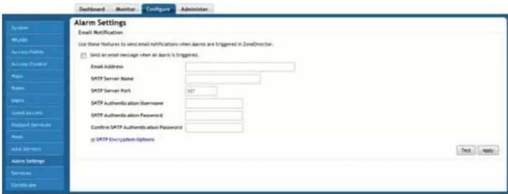
FIG. 35 Configure Tab - Alarm Settings
| Configure Tab - Alarm Settings | |
| Email Notification: Enable this option to send an email message when an alarm is triggered. | |
| Email Address: The Email address to which the message should be sent | |
| SMTP Server Name: The name of the SMTP server being accessed. | |
| SMTP Server Port: The SMTP server port being accessed. | |
| SMTP AuthenticationUsername: | The username authorized for the SMTP server. |
| SMTP AuthenticationPassword: | The password authorized for the SMTP server. |
| Confirm SMTP AuthenticationPassword: | Re-enter the password. |
| SMTP Encryption Options: If your server allows TLS encryption, click the box to allow it. | |
Setting Up Email Alarm Notification
If an alarm condition is detected, the NXA-WAPZD1000 will record it in the event log. If you prefer, an email notification can be sent to a configured email address of your choosing.
To enable an Email alarm notification:
- From the Browser-Based Configuration Pages, go to Configure > Alarm Settings. The Email Notification form appears.
- To enable email notification, select the Send an email message when an alarm is triggered check box.
- Configure the settings listed in the following table:
| SMTP Settings For Email Notification | |
| SMTP Setting Description | |
| SMTP Server Name: Type the full name of the server provided by your ISP or mail administrator. Often, the SMTP server name is in the format smtp.company.com. | |
| SMTP Server Port: Type the SMTP port number provided by your ISP or mail administrator. Often, the SMTP port number is 25 or 587. The default SMTP port value is 587. | |
| SMTP Settings For Email Notification (Cont.) | |
| SMTP Authentication Username: | Type the user name provided by your ISP or mail administrator. This might be just the part of your email address before the @ symbol, or it might be your complete email address. If you are using a free email service (such as Hotmail or Gmail), you typically have to type your complete email address. |
| SMTP Authentication Password: | Type the password that is associated with the username above. |
| Confirm SMTP Authentication Password: | Retype the password you typed above to confirm. |
| SMTP Encryption Options: | If your mail server uses TLS encryption, click the SMTP Encryption Options link, and then select the TLS check box. Additionally, select the STARTTLS check box that appears after you select the TLS check box. Check with your ISP or mail administrator for the correct encryption settings that you need to set. |
-
To verify that the NXA-WAPZD1000 can send alarm messages using the SMTP settings you configured, click the Test button.
-
If the device is able to send the test message, the message Success! appears at the bottom of the Email Notification page. Continue to Step 5.
-
If the device is unable to send the test message, the message Failed! appears at the bottom of the Email Notification page. Go back to Step 3., and then verify that the SMTP settings are correct.
-
Click Apply. The email notification settings you configured become active immediately.
Events That Trigger Alarm Notifications
The following events trigger email alarm notifications in the NXA-WAPZD1000:
- Detection of rogue AP: When the NXA-WAPZD1000 detects a rogue AP on the network, it sends the following alarm message: A new rogue {rogue AP name} with {SSID} is detected.
- Detection of ad hoc network: When the NXA-WAPZD1000 detects an ad hoc network, it sends the following alarm message: A new ad-hoc network {adhoc network name} with {SSID} is detected.
- Lost contact with AP: When the NXA-WAPZD1000 loses communication with an AP and is unable to re-establish communication after 20 minutes, it sends the following alarm message: Lost contact to {AP name}.
- Detection of an SSID-spoofing AP: When the NXA-WAPZD1000 detects that an unauthorized AP is spoofing the SSID of one of your APs, it sends the following alarm message: A new SSID-spoofing {rogue AP name} with {SSID} is detected.
- Detection of a MAC address-spoofing AP: When the NXA-WAPZD1000 detects that an unauthorized AP is spoofing the MAC address of one of your APs, it sends the following alarm message: A new MAC-spoofing {rogue AP name} with {SSID} is detected.
- Detection of rogue DHCP server: When the NXA-WAPZD1000 detects a rogue DHCP server on the network, it sends the following alarm message: Rogue DHCP server on {ip} is detected.
When any of these events occur, the NXA-WAPZD1000 sends an email notification to the email address that you previously specified.
With the exception of the Lost contact with AP event, the NXA-WAPZD1000 only sends one email alarm notification for each event. If the same event happens again, no alarm will be sent until you clear the alarm on the Monitor > All Alarms page. On the other hand, the device sends a new alarm notification each time the Lost contact with AP event occurs.

Services
The Services page allows control of several helpful options for network management.
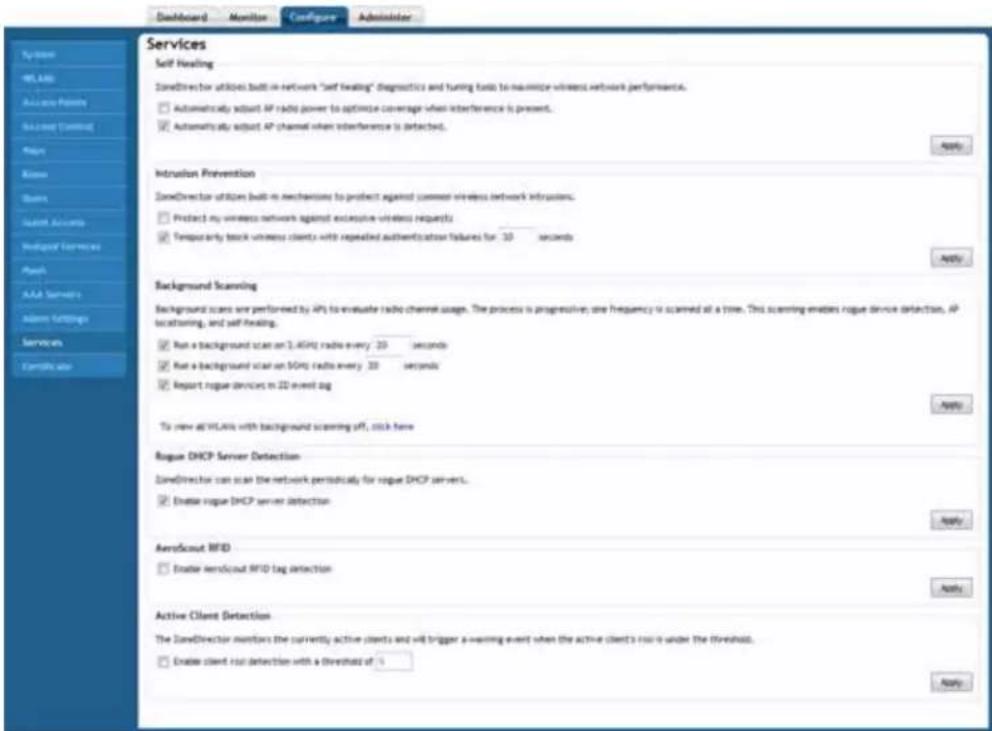
FIG. 36 Configure Tab - Services
| Configure Tab - Services | |
| Self Healing: The NXA-WAPDZD1000 has the capability to perform automatic network adjustments to the existing monitoring functions in order to enhance performance, so that it can efficiently shift AP-specific settings and resources to improve coverage. | |
| Intrusion Detection: The NXA-WAPDZD1000 has built-in intrusion prevention features that help protect the wireless network from excessive requests and intrusion attempts. | |
| Background Scanning: The NXA-WAPDZD1000 regularly samples the activity in all Access Points to assess radio frequency (RF) usage, to detect rogue APs and to determine which APs are near each other for mesh optimization. | |
| Rogue DHCP Server Detection: The NXA-WAPZD1000 has a rogue DHCP server detection feature that can help you prevent connectivity and security issues that rogue DHCP servers may cause. | |
| AeroScout RFID: Selecting this option allows the NXA-WAPZD1000 to detect AeroScout RFID tags. | |
| Active Client Detection: | Enabling active client detection allows the NXA-WAPZD1000 to trigger an event when a client with a low signal strength joins the network. |
Configuring Self Healing Options
The NXA-WAPDZD1000 has the capability to perform automatic network adjustments to the existing monitoring functions in order to enhance performance, so that it can efficiently shift AP-specific settings and resources to improve coverage. This capability is called "Self Healing."
To configure the self-healing options:
-
Go to Configure > Services.
-
Review and change the following self-healing options:
-
Automatically adjust AP radio power to optimize coverage where interference is present: If this capability is activated and the Tx power of a radio is Auto, the AP's transmit power will be automatically reduced or maximized to provide the best wireless service.
-
Automatically adjust AP channel when interference is detected: If interference of any kind is detected in an AP, the radio frequency will be switched automatically.
-
Click the Apply button in the same section to save your changes. The NXA-WAPZD1000 issues necessary AP power and/or channel updates at 10 minute intervals.
Configuring Intrusion Prevention Options
The NXA-WAPDZD1000 has built-in intrusion prevention features that help protect the wireless network from excessive requests and intrusion attempts.
To configure the intrusion prevention options:
- Go to Configure > Services.
-
In the Intrusion Prevention section, configure the following settings:
-
Protect my wireless network against excessive wireless requests: If this capability is activated, excessive 802.11 probe request frames and management frames launched by malicious attackers will be discarded.
-
Temporarily block wireless clients with repeated authentication failures for [ ] seconds: If this capability is activated, any clients that repeatedly fail in attempting authentication will be temporarily blocked for a period of time. Default is 30 seconds.
-
Click the Apply button in the same section to save your changes.
Configuring Background Scanning
As a key element of your network monitoring, the NXA-WAPDZD1000 regularly samples the activity in all Access Points to assess radio frequency (RF) usage, to detect rogue APs and to determine which APs are near each other for mesh optimization.
These scans sample one channel at a time in each AP, so as not to interfere with network use. This information is then applied in Map View (page 27) and other NXA-WAPDZD1000 monitoring features. You can, if you prefer, customize the automatic scanning of RF activity, deactivate it if you feel it's not helpful, or adjust the frequency, if you want scans at greater or fewer intervals. Note that background scanning must be enabled for the NXA-WAPDZD1000 to detect rogue APs and rogue DHCP servers on the network.
To configure background scanning:
- Go to Configure > Services.
-
In the Background Scanning section, configure the following options:
-
Run background scan every [ ]: Select this check box, and then type the time interval (in seconds, default is 20) that you want to set between each scan. If you want to disable background scanning, clear the check box; this should result in a minor increase in AP performance, but removes the detection of rogue APs from NXA-WAPDZD1000 monitoring. You can also decrease the scan frequency, as less frequent scanning improves overall AP performance.
-
Report rogue devices in ZD event log: Select this check box if you want the NXA-WAPDZD1000 to record details about detected rogue devices to its event logs.
-
Click the Apply button that is in the same section to save your settings.

You can also disable background scanning on a per-WLAN basis from the Configure > WLANS page. To disable scanning for a particular WLAN, click the Edit link next to the WLAN for which you want to disable scanning, open Advanced Options, and click the check box next to Disable Background Scanning.
To see whether background scanning is enabled or disabled for a particular AP, go to Monitor > Access Points, and click on the AP's MAC address. The access point detail screen displays the background scanning status for each radio.
Enabling Rogue DHCP Server Detection
A rogue DHCP server is a DHCP server that is not under the control of network administrators and is therefore unauthorized. When a rogue DHCP server is introduced to the network, it could start assigning invalid IP
addresses, disrupting network connections or preventing client devices from accessing network services. It could also be used by hackers to compromise network security. Typically, rogue DHCP servers are network devices (such as routers) with built-in DHCP server capability that has been enabled (often, unknowingly) by users.
The NXA-WAPZD1000 has a rogue DHCP server detection feature that can help you prevent connectivity and security issues that rogue DHCP servers may cause. When this feature is enabled, the NXA-WAPZD1000 scans the network every five seconds for unauthorized DHCP servers and generates an event every time it detects a rogue DHCP server.
The conditions for detecting rogue DHCP servers depend on whether the NXA-WAPZD1000's own DHCP server is enabled:
- If the built-in DHCP server is enabled, the NXA-WAPZD1000 will generate an event when it detects any other DHCP server on the network.
- If the built-in DHCP server is disabled, the NXA-WAPZD1000 will generate events when it detects two or more DHCP servers on the network. You will need to find these DHCP servers on the network, determine which ones are rogue, and then disconnect them or shut down the DHCP service on them.
To enable rogue DHCP server detection on the NXA-WAPZD1000:
- Go to Configure > Services.
- In the Rogue DHCP Server Detection section, select the Enable rogue DHCP server detection check box.
- Click the Apply button that is in the same section.
Regularly checking the All Events/Activities page (page 39) periodically to determine if the NXA-WAPZD1000 has detected any rogue DHCP servers is recommended. If the NXA-WAPZD1000 detected any rogue DHCP server, you will see the following event on the All Events/Activities page:
Rogue DHCP server on [IP_address] has been detected
If the check box is cleared, the NXA-WAPZD1000 will not generate these events.
Active Client Detection
Enabling active client detection allows the NXA-WAPZD1000 to trigger an event when a client with a low signal strength joins the network.
To enable active client detection:
- Go to Configure > Services, and scroll down to the Active Client Detection section.
- Click the check box next to Enable client detection... and enter an RSSI threshold, below which an event will be triggered.
- Click Apply to save your changes.
A low severity event is now triggered each time a client connects with an RSSI lower than the threshold value entered. Go to Monitor > All Events/Activities (page 39) to monitor these events.
Certificate
If you use HTTPS to connect to the Browser-Based Configuration Pages, a security warning appears every time you connect. This is because the default SSL certificate (or security certificate) that the NXA-WAPZD1000 is using for HTTPS communication is signed by Ruckus Wireless and is not recognized by most Web browsers.
If you want to prevent these security warnings from appearing, you will need to import an SSL certificate that was issued by a recognized certificate authority (for example, VeriSign, Thawte, etc). If you do not have an SSL certificate yet, you will need to create a certificate signing request and purchase a certificate from a certificate authority.
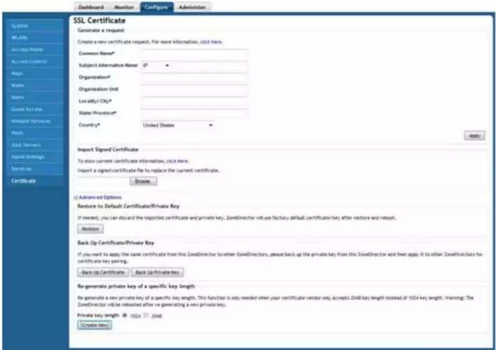
FIG. 37 Configure Tab - Certificate page
| Configure Tab - Certificate | |
| Generate a Request: | |
| Common Name Enter the NXA-WAPZD1000's Fully Qualified Domain Name (FQDN). | |
| Subject Alternative Name: | (Optional) Select either IP or DNS from the menu and enter either alternative IP addresses or alternate DNS names. |
| Organization: Type the complete legal name of your organization (for example, Ruckus Wireless, Inc.). Do not abbreviate your organization name. | |
| Organization Unit: | (Optional) Type the name of the division, department, or section in your organization that manages network security (for example, Network Management). |
| Locality/City: Type the city where your organization is legally located (for example, Sunnyvale). | |
| State/Province: | Type the state or province where your organization is legally located (for example, California) Do not abbreviate the state or province name. |
| Country: Select your country or region from the pull-down menu. | |
| Import Signed Certificate: | Use this option to import a signed certificate file to replace the current certificate. |
Creating a Certificate Signing Request
If you do not have an existing SSL certificate, you will need to create a certificate signing request (CSR) file and send it to a certificate authority (CA) to purchase an SSL certificate. The Browser-Based Configuration Pages provide a form that you can use to create the CSR file. Fields with an asterisk (*) are required entries. Those without an asterisk are optional.
To create a certificate request file:
1. Go to Configure > Certificate.
- In the Generate a Request section, complete the following options:
- Common Name*: Enter the NXA-WAPZD1000's Fully Qualified Domain Name (FQDN). Typically, this will be "zonedirector.[your company].com". You can also enter the NXA-WAPZD1000's IP address (e.g., "192.168.0.2"), or a familiar name by which the NXA-WAPZD1000 will be accessed in your browser (e.g., by device name such as "ZoneDirector").

Using the FQDN as the Common Name if possible is highly recommended. If your network does not have a DNS server, you may use the NXA-WAPZD1000's IP address instead. However, note that some CAs may not allow this.
- If you wish to access the NXA-WAPZD1000 from a public network via the internet, you must use a Fully Qualified Domain Name (FQDN).
- In all cases when using a familiar name there must be an appropriate private or public DNS entry to resolve the familiar name to the NXA-WAPZD1000's IP address.
- If you use a familiar name, this name will be shown in the browser's URL whenever accessing the NXA-WAPZD1000 (i.e., administrator interface, standard captive portal and guest access captive portal).
- Subject Alternative Name: (Optional) Select either IP or DNS from the menu and enter either alternative IP addresses or alternate DNS names.
- Organization*: Type the complete legal name of your organization (for example, Ruckus Wireless, Inc.). Do not abbreviate your organization name.
- Organization Unit: (Optional) Type the name of the division, department, or section in your organization that manages network security (for example, Network Management).
- Locality/City*: Type the city where your organization is legally located (for example, Sunnyvale).
- State/Province*: Type the state or province where your organization is legally located (for example, California) Do not abbreviate the state or province name.
-
Country*: Select your country or region from the pull-down menu.
-
Click Apply. A dialog box appears and prompts you to save the CSR file (myreq.csr) that you have just created.
-
Save the file to your computer.
-
Go to a certificate authority's Web site and follow the instructions for purchasing an SSL certificate.
-
When you are prompted for the certificate signing request, copy and paste the content of the text file that you saved in Step 4., and then complete the certificate purchase.
After the certificate authority approves your CSR, you will receive the SSL certificate via email. The following is an example of a signed certificate that you will receive from a certificate authority:
----BEGIN CERTIFICATE----
MIIFVjCCBD6gAwIBAgIQLfaGuqKukMumWhbVf5v4vDANBgkqhkiG9w0BAQUFADCBs
DELMAkGA1UEBhMCVVMxFzAVBgNVBAoTDlZlcmlTaWduLCBJbmMuMR8wHQYDVQQLBg
EFBQcBAQRtMGswJAYIKwYBBQUHMAGGGGh0dHA6Ly9vY3NwLnZlcmlzaWduLmNvbTB
DBggrBgEFBQcwAoY3aHR0cDovL1NWU1NLY3VyZS1haWEudmVyaXNpZ24uY29tL1NW
U1NLY3VyZTIwMDUtYWlhLmN1cjBuBggrBgEFBQcBDARiMGChXqBcMFowWDBWFglpb
WFnZS9naWYwITAfMAcGBSsOAwIaBBRLa7kolgYMu9BSOJsprEsHiyEFGDAmFiRodH
RwOi8vbG9nby52ZXJpc2lnbi5jb20vdnNsb2dvMS5naWYwDQYJKoZIhvcNAQEFBQA
DggEBAI/S2dmm/
kgPeVAlsIHmx751o4oq8+fwehRDBmQDaKiBvVXGZ5ZMnoc3DMyDjx0SrI91kPsn22
3CV3UVBZo385g1T4iKwXgcQ7WF6QcUYOE6HK+4ZGcHermFf3fv3C1FoCjq+zEu8Zb
oUf3fWbGprGRA+MR/dDIldTPTSUG7/zWjX05jc//0pykS1dw/
q8hgO8kq30S8JzCwkqrXJfQ050N4TJtgb/
YC4gwH3BuB9wqpRjUahTiK1V1ju9bHB+bFkMWIIMIXc1Js62JClWzwFgaGUS2DLE8
xCQ3wU1ez8RUPGnwSxAYTZ2N7zDxYDP2tEiO5j2cXY7O8mR3ni0C30=fn
----END CERTIFICATE----
- Copy the content of the signed certificate, and then paste it into a text file. Save the file. You may now import the signed certificate into the NXA-WAPZD1000.
Importing an SSL Certificate
If you already have an SSL certificate, you can import it into the NXA-WAPZD1000 and use it for HTTPS communication. To complete this procedure, you will need the SSL certificate file and the key pair password that you set when you created the certificate signing request (CSR) file.
To import an SSL certificate:
- Copy the certificate file to a location (either on the local drive or a network share) that you can access from the Browser-Based Configuration Pages.
- Log in to the Browser-Based Configuration Pages, and then click Configure > Certificate.
- Under Import Certificate, click Browse, and then go to the location where you saved the certificate file.
- Click Open. If the certificate file that you selected is valid, an Import button appears.
- Click Import to import the certificate file to the NXA-WAPZD1000.
- After importing the certificate, the NXA-WAPZD1000 will check if the imported certificate matches the device's private key. If the certificate matches the private key, the NXA-WAPZD1000 asks whether you want to install the certificate and reboot, or install additional intermediate certificates.
- If the SSL certificate you imported does not match the NXA-WAPZD1000's private key, you can try another certificate, or click the click here link to import a private key.
- If you click the click here link to import a private key, the following dialog is displayed:

FIG. 38 Import Private Key dialog box
- After you import a private key, you must import the signed certificate again (see Step 3.).
- If you choose to import additional intermediate certificates, the NXA-WAPZD1000 first installs the new signed certificate, then prompts you to import intermediate certificates.
-
Once you have finished importing the new signed certificate and any intermediate certificates, click Import to complete the installation and reboot the NXA-WAPZD1000.
-
Finally, you can also import a wildcard certificate. If you do this, the NXA-WAPZD1000 will prompt you to fill in the NXA-WAPZD1000 redirect URL before proceeding.
- Once the private key matches and intermediate certificates are imported, clicking the Import button will start the Loading Certificate process. The following screen is displayed during the install and reboot process:

Ruckus™
WIRELESS
ZoneDirector
Loading Certificate...
ZoneDirector is loading the certificate file. Once ZoneDirector is in service, you will be automatically reconnected to http://localhost
FIG. 39 Loading Certificate screen
You have completed installing a new signed SSL certificate to the NXA-WAPZD1000. This allows you to connect to the NXA-WAPZD1000 securely using HTTPS without encountering browser security warnings.
SSL Certificate Advanced Options
The NXA-WAPZD1000 also provides three features for managing SSL certificates/private keys easily through the Browser-Based Configuration Pages:
- Restore: Allows you to easily restore the factory default certificate/key at any time -- in case you have imported an SSL certificate that causes problems, you can always revert to the factory default and start over.
- Back Up Certificate/Private Key: Allows you to save the key for use in another NXA-WAPZD1000 or keep a copy in case the device needs to be factory reset and loses its current key.
- Re-Generate Private Key: Only used to generate a new private key of a different length (when required by the Certificate Authority).
Saving an SSL Certificate or Private Key
Saving an SSL certificate to a local computer can be useful when deploying two NXA-WAPZD1000s in a Smart Redundancy configuration. Using the advanced options, you can export an SSL certificate from one device to the other.
To share an SSL certificate and private key between two devices:
- Go to Configure > Certificates.
- Click Advanced Options to expand the options.
- Click Back Up Certificate, and save the file to your local computer.
- Click Back Up Private Key, and save the file to your local computer.
- Log in to the peer NXA-WAPZD1000, and import the certificate. (For more information, please refer to the Importing an SSL Certificate section on page 108.)
-
After the certificate has been imported, the NXA-WAPZD1000 checks for private key match.
-
If the imported certificate does not match the NXA-WAPZD1000's private key, a warning message appears (FIG. 40).
Import Signed Certificate
To show current certificate information, click here.
Import a signed certificate file to replace the current certificate.
Browse
The uploaded certificate file does not match ZoneDirector's private key.
Please try another certificate file or click here to import private key.
FIG. 40 The imported certificate does not match ZoneDirector's private key
- Click the click here link, and an Import Private Key dialog appears (FIG. 41).
Import Private Key
Import private key to match your certificate. After importing the private key, you must import your signed certificate again.
演元
FIG. 41 Importing a private key
-
Click Browse and locate the private key file you saved in step 3.
-
Click Import to finish importing the private key to the NXA-WAPZD1000.
Using an External Server for Administrator Authentication
The NXA-WAPZD1000 supports additional administrator accounts that can be authenticated using an external authentication server such as RADIUS, LDAP or Active Directory. Two types of administrative privileges can be assigned to these administrator accounts:
● Full Privileges - Allow all types of configuration and management tasks
- Limited Privileges - Allow monitoring operations only
This section provides basic instructions for setting up the NXA-WAPZD1000 to authenticate additional administrator accounts with an external authentication server. For more information on AAA server configuration, please refer to the Using an External AAA Server section on page 96.
To authenticate NXA-WAPZD1000 administrators using an AAA server:
- Set up Group Attributes on the AAA server.
• RADIUS:
- Ruckus Wireless private attribute
- Vendor ID: 25053
- Vendor Type/Attribute Number: 1 (Ruckus-User-Groups)
- Value Format: group_attr1, group_attr2, group_attr3,...
- Cisco private attribute (if your network is using a Cisco access control server)
- Vendor ID: 9
- Vendor Type / Attribute Number: 1 (Cisco-AVPair)
- Value Format: shell:roles=?hgroup_attr1 group_attr2 group_attr3 ...?h
• Active Directory or LDAP:
Set up two groups, one for administrators with Full Privileges and another for administrators with Limited Privileges.
Populate these groups with users to whom you want to grant administrator access. One way to do this is to edit each user's Member of profile and add the group to which you want the user to belong. Remember the group names that you set; you will enter this information when you create administrator roles in the NXA-WAPZD1000 (see Step 3).
- Set up the NXA-WAPZD1000 to use an AAA server (Configure > AAA Servers).
-
Create an Administrator Role in the NXA-WAPZD1000 (Configure > Roles).
-
Allow access to all/specific WLANs.
- Allow/deny Guest Pass Generation.
- Ensure that Allow ZoneDirector Administration is enabled, and choose Full Privileges or Limited Privileges.

If you do not select the Allow ZoneDirector Administration check box, administrators that are assigned this role will be unable to log into the NXA-WAPZD1000 even if all other settings are configured correctly.
- Test your authentication settings (Configure > AAA Servers > Test Authentication Settings).
- Specify AAA server to use (Administrator > Preferences > Authenticate with Auth Server).
- Verify that the Fallback to admin name/password if failed check box is selected. Keeping this check box selected ensures that administrators will still be able to log into the Browser-Based Configuration Pages even when the authentication server is unavailable.
You have completed setting up the NXA-WAPZD1000 to use external servers for administrator authentication. Whenever a user with administrator privileges logs into the Browser-Based Configuration Pages, an event will be recorded. The following is an example of the event details that you will see:
Admin [user_name] login (authenticated by {Authentication Server} with {Role}).
Administer Tab
The Administer Tab contains many of the default or baseline settings necessary for proper management of an NXA-WAPZD1000 network. It contains pages for changing preferences, restarting, upgrading, and registering your NXA-WAPZD1000 and any connecting NXA-WAP1000 devices.

When making any changes in the Browser-Based Configuration Pages, you must click Apply before you navigate away from the page or your changes will not be saved.
Preferences
You should change your NXA-WAPZD1000 administrator login password on a monthly basis, but the administrator user name should be changed only if necessary.
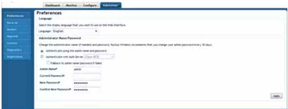
FIG. 42 Administer Tab - Preferences
| Administer Tab - Preferences | |
| Language: Select the display language that you want to use on the Browser-Based Configuration Pages. | |
| Administrator Name/Password: | |
| Admin Name: Enter the administrator's username. | |
| Current Password: Enter the administrator's current password. | |
| New Password: Enter the new password. | |
| Confirm New Password: Enter the new password a second time. |
Changing the NXA-WAPZD1000 Administrator User Name and Password

If authentication with an external server is enabled and the Fallback to admin name/password if failed check box is disabled, you will be unable to edit the user name and password.
To edit the user name and password:
- Select the Fallback to admin name/password if failed check box to enable the user name and password boxes.
- Change the user name and password.
- Clear the Fallback to admin name/password if failed check box.
- Click Apply to save your changes.
To edit or replace the current name or password:
-
Go to Administer > Preferences.
-
When the Preferences page appears, you have the following options under Administrator Name/Password:
-
Admin Name: Delete the text in this field and type the new administrator account name (used solely to log into the NXA-WAPZD1000 via the Browser-Based Configuration Pages.)
-
Password/Confirm Password: Delete the text in both fields and type the same text for a new password.
-
Click Apply to save your settings. The changes go into effect immediately.
Changing the Browser-Based Configuration Pages Display Language
Depending on your preferences, you can change the language in which the Browser-Based Configuration Pages are displayed in your Web browser. The default is “English.” This change only affects how the actual interface appears, and does not modify either OS/system or browser settings, which are managed through other processes.
- Go to Administer > Preferences.
- When the Preferences page appears, choose your preferred language from the Language drop-down menu.

NOTE
This only affects how the Browser-Based Configuration Pages appear, and does not modify either the operating system or Web browser settings.
- Click Apply to save your settings. The changes go into effect immediately.
Back up/Restore
After you have set up and configured your wireless network, you may want to back up the full configuration. The resulting archive can be used to restore your NXA-WAPZD1000 and network. And, whenever you make additions or changes to the setup, you can create new backup files at that time, too.
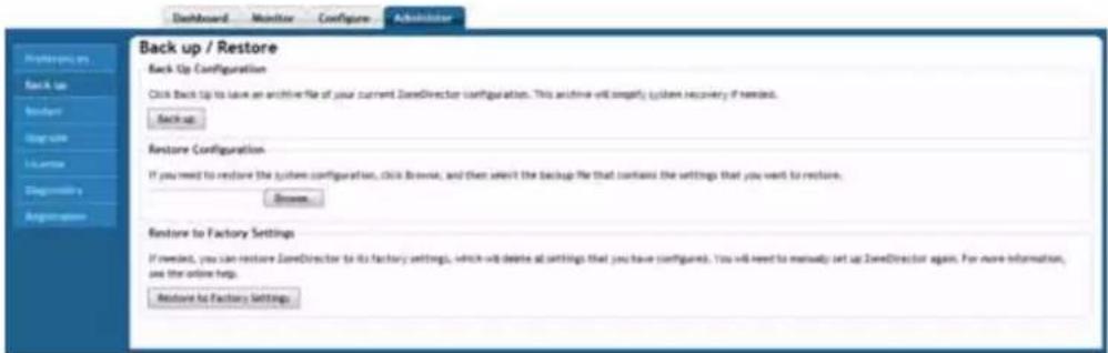
FIG. 43 Administer Tab - Back up/Restore
| Administer Tab - Back Up/Restore | |
| Back Up Configuration: | Click Back Up to save an archive file of your current NXA-WAPZD1000 configuration |
| Restore Configuration: | Click Browse, and then select the backup file that contains the settings that you want to restore |
| Restore to Factory Settings: | Click Restore to Factory Settings to restore the NXA-WAPZD1000 to its factory settings. This will delete all previously configured settings. |
Backing Up a Network Configuration
To back up a network configuration:
- Go to Administer > Backup.
- Under the Backup Configuration sections, click Back Up. The File Download dialog box appears.
- Click Save.
- When the Save As dialog box appears, enter a name for this archive file, pick a destination folder, then click Save.
- Make sure the filename ends in a ".TGZ" extension.
- When the Download Complete dialog box appears, click Close.
Restoring Archived Settings to the NXA-WAPZD1000

Restoring a backup file will automatically reboot the NXA-WAPZD1000 and all APs that are currently associated with it. Users associated with these APs will be temporarily disconnected; wireless access will be restored automatically after the NXA-WAPZD1000 and the APs have completed booting up.
To restore archived settings to the NXA-WAPZD1000:
- Go to Administer > Backup.
- Review the Restore Configuration instructions, and then click Browse.
- Use the Browse dialog box to locate the backup file.
- Select the file, and then click Open. Three restore options appear:
- Restore everything: Select this option if you want the device to use all the settings configured in the backup file (including the IP address, wireless settings, and access control list, among others).

If you use the Restore everything option to restore settings from one NXA-WAPZD1000 to another, note that wireless clients reporting to the AP managed by the first NXA-WAPZD1000 unit will need to go through Zero-IT activation again to obtain new client certificates. Zero-IT activation is enabled by default, therefore no manual configuration is required from you.
- Restore everything except system name/IP address: Select this option if you are deploying a second NXA-WAPZD1000 for failover purposes.
- Restore only configurations about WLANs, Access Controls, Roles, and Users: Select this option if you want to use the backup file as a configuration template.
5. Click the Restore button.
The NXA-WAPZD1000 will now restore the backup file. During this process, the device automatically logs you out of the Browser-Based Configuration Pages. When the restore process is complete, the device automatically restarts and your wireless network will be ready for use again.
Restoring the NXA-WAPZD1000 to Default Factory Settings
In certain extreme conditions, you may want to reinitialize the NXA-WAPZD1000, and reset it to factory default state. In this state, the network is almost ready for use, but all your user/guest/log and other records, accounts and preference configurations would need to be manually reconfigured.

When this procedure is complete, you will need to redo a complete setup. If the NXA-WAPZD1000 is on a live network, a new IP address may be assigned to the system. In this case, the system can be discovered by a UPnP client application, such as Windows "My Network Places." If there is no DHCP server on the connected network, the system's default IP address is 192.168.0.2 with subnet mask 255.255.255.0.
To reset your NXA-WAPZD1000 to factory default settings:
- Go to Administer > Backup.
- Click the Restore to Factory Settings button.
- Owing to the drastic effect of this operation, one or more confirmation dialog boxes will appear. Click OK to confirm this operation.
When this process begins, you will be logged out of the Browser-Based Configuration Pages.
When the reset is complete, the Status LED is a blinking red, then a blinking green, indicating that the system is in the "factory default" state. After you complete the Setup Wizard, the Status LED will be steady green.
Alternate Factory Default Reset Method
If you are unable to complete a software-based resetting of the NXA-WAPZD1000, you can do the following "hard" restore:

Do not disconnect the NXA-WAPZD1000 from its power source until this procedure is complete.
To perform a "hard" factory default reset:
- Locate the Reset pin hole on the front panel of the NXA-WAPZD1000 (FIG. 1).
- Insert a straightened paper clip in the hole and press for at least 5 seconds.
After the reset is complete, the Status LED blinks red, then blinks green, indicating that the system is in factory default state.
After you complete the Setup Wizard, the Status LED will be steady green.
Restart/Shutdown
This page allows you to make a remote reboot or shutdown of the NXA-WAPZD1000 without having physical access to the device.
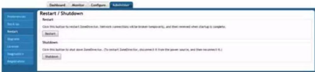
FIG. 44 Administer Tab - Restart/Shutdown
Restarting the NXA-WAPZD1000
The NXA-WAPZD1000 three "restart" options:
- To disconnect and then reconnect the NXA-WAPZD1000 from the power source,
- To follow this procedure, which simultaneously shuts down the NXA-WAPZD1000 and all APs, then restarts all devices
● A restart of individual APs
To restart the NXA-WAPZD1000 and all currently active APs:
1. Go to Administer > Restart.
2. When the Restart/Shutdown features appear, click Restart.
You will be automatically logged out of the NXA-WAPZD1000. After a minute, when the Status LED is steadily lit, you can log back into the device.
Upgrade
Check the AMX Web site on a regular basis for updates that can be applied to your Ruckus Wireless network devices — to the NXA-WAPZD1000 and all your NXA-WAP1000 APs. After downloading any update package to a convenient folder on your administrative PC, you can complete the network upgrade of both the NXA-WAPZD1000 and APs by following the steps detailed below.
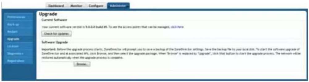
FIG. 45 Administer Tab - Upgrade
| Administer Tab - Upgrade | |
| Current Software: | Click theCheck for Updatesbutton to see if software upgrades are available. |
| Software Upgrade: Select a location | to save a backup of the NXA-WAPZD1000 settings. |

Upgrading the NXA-WAPZD1000 and the APs will temporarily disconnect them (and any associated clients) from the network. To minimize network disruption, performing the upgrade procedure at an off-peak time is highly recommended.
To upgrade the NXA-WAPZD1000 firmware after downloading the update package:
- Go to Administer > Upgrade.
- Under the Software Upgrade section, click Browse. The Browse dialog box appears.
- Browse to the location where you saved the upgrade package, and then click Open.
-
When the upgrade file name appears in the text field, the Browse button becomes the Upgrade button.
-
Click Upgrade.
The NXA-WAPZD1000 will automatically log you out of the Browser-Based Configuration Pages, run the upgrade, and then restart itself. When the upgrade process is complete, the Status LED on the device (FIG. 1) is steadily lit. You may now log back into the Browser-Based Configuration Pages as Administrator.

The full network upgrade is successive in sequence. After the NXA-WAPZD1000 is upgraded, it will contact each active AP, upgrade it, and then restore it to service.

The AP uses FTP to download firmware updates from the NXA-WAPZD1000. If you have an access control list (ACL) or firewall between the NXA-WAPZD1000 and the AP, make sure that FTP traffic is allowed to ensure that the AP can successfully download the firmware update.
Performing an Upgrade with Smart Redundancy
If you have two NXA-WAPZD1000s in a Smart Redundancy configuration, the procedure is similar. Note however, that the active and backup devices will reverse roles during an upgrade.
To upgrade redundant NXA-WAPZD1000s:
- Log in to the active NXA-WAPZD1000 or the shared Management Interface.
- Go to Administer > Upgrade.
- Under the Software Upgrade section, click Browse. The Browse dialog box appears.
- Browse to the location where you saved the upgrade package, and then click Open.
- When the upgrade file name appears in the text field, the Browse button becomes the Upgrade button.
- Click Upgrade. The backup NXA-WAPZD1000 is upgraded first.
- When the backup NXA-WAPZD1000 upgrade is complete, the backup device reboots and becomes active (begins accepting AP requests), while the original active device enters backup state and begins its own upgrade process.
- All APs are now associated to the original backup NXA-WAPZD1000 (which is now the active device), and begin upgrading AP firmware to the new version.
- Each AP reboots after upgrading.
License
Depending on the number of Ruckus Wireless APs you need to manage with your NXA-WAPZD1000, you may need to upgrade your license. Contact your authorized AMX reseller to purchase an upgrade license. Once you load the license via the Browser-Based Configuration Pages, it takes effect immediately.
Current license information (description, PO number, status, etc.) is displayed on the Browser-Based Configuration Pages.
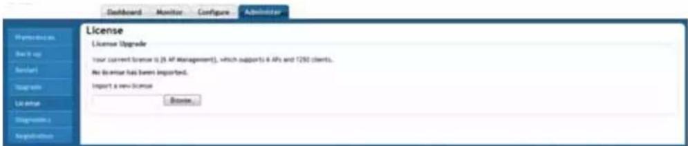
FIG. 46 Administer Tab - License

The system does not reboot or reset after a license is imported.
Importing a New License File
To import a new license file:
-
Go to Administer > License.
-
Click Browse to find your license.
-
Once you find your license and close the Browse window, the NXA-WAPZD1000 immediately attempts to validate and install the license.
Diagnostics
The Diagnostics page allows radio frequency scans and saving of debug information.
![Dashboard Monitor Configure Administrator Diagnostics Manual Scan Click this button to initiate a radio frequency scan. [ALERT] This will immediately sample all active frequencies and may temporarily interfere with wireless network communication. Scan Save Debug Info If you request assistance from Ritusus Wireless technical support, you may be asked to supply detailed debug information from ZoneDirector. Click the "Save Debug Info" button to generate the debug log file, and then save it to your computer. Save Debug Info Debug Logs □ Debug Components □ System management □ Mesh □ Smart Redundancy □ web Authentication □ RF management □ BandOS □ Hotspot Services □ Access Points □ Network Management □ 802.1x □ Web server □ 802.11 □ Dynamic VLAN □ Debug log per AP's or client's mail address (e.g. validation) Notes AP Logs To show current AP's logs, click here.](/content/2026/05/897082/images/a3bd8ecb264e163d90dbf5ecc47672c49904137a8710e0142f5239af52a833b9.jpg)
FIG. 47 Administer Tab - Diagnostics
| Administer Tab - Diagnostics | |
| Manual Scan: | Click the Debug button to initiate a radio frequency scan |
| Save Debug Info: | Click the Save Debug Info button to generate the debug log file, and then save it to your computer. |
| Debug Logs: Select the particular debug logs to be saved. | |
| AP Logs: Click the link to view the current AP logs. | |
Generating a Debug File
Do not start this procedure unless asked to do so by technical support staff.

If requested to generate and save a debug file:
- Go to Administer > Diagnostics.
- Select the items under Debug Components as directed by AMX technical support, or check the box next to Debug Components to select all. (If they are already selected, skip this step.)
- If you are instructed to save only log information for a specific AP or client, you can select the check box next to Debug log per AP's or client's mac address, then enter either the MAC address in the adjacent field.
- Click Apply to save your settings.
- In the Save Debug Info section, click Save Debug Info.
- When the File Download dialog box appears, select Save File, and click OK.
- When the Save As dialog box appears, pick a convenient destination folder, type a name for the file, and click Save.
- When the Download Complete dialog box appears, click Close.
After the file is saved, you can email it to the technical support representative.

The debug (or diagnostics) file is encrypted and only AMX support representatives have the proper tools to decrypt this file.
Viewing Current AP Logs
While the NXA-WAPZD1000 debug files can not be directly viewed, you can display a list of recent AP activity from the Browser-Based Configuration Pages.
To view AP logs:
-
Go to Administer > Diagnostics, and locate the AP Logs section.
-
Click the Click Here link next to To show current AP logs.... The log data is displayed in the text box beneath the link.
Product Registration
AMX encourages you to register your NXA-WAPZD1000 product to receive updates and important notifications, and to make it easier to receive support in case you need to contact AMX for customer assistance. You can register your NXA-WAPZD1000 along with all of your access points in one step using the NXA-WAPZD1000's Registration form (FIG. 48).
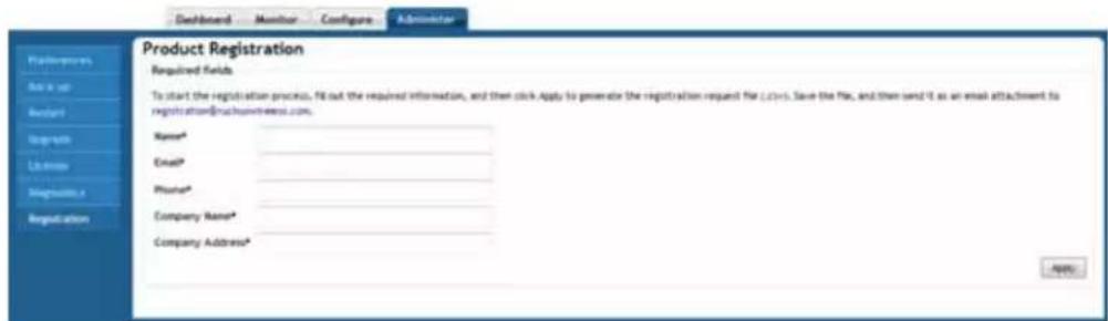
FIG. 48 Administer Tab - Product Registration

To ensure that all registration information for all of your APs is included, be sure to register after all APs have been installed. If you register the NXA-WAPZD1000 before installing the APs, the registration will not include AP information.
To register your NXA-WAPZD1000:
- In the Browser-Based Configuration Pages, click on the Administer tab and then choose Registration.
- Enter your information on the Registration page, and click Apply.
- The information is sent to a CSV file that opens in a spreadsheet program (if you have one installed).
- Email the CSV file (which includes the serial number and MAC address of your NXA-WAPZD1000 and all known access points, in addition to your contact information) to register@ruckuswireless.com.
Toolbox
The drop-down menu at the top right corner of the Browser-Based Configuration Pages provides access to the RealTime Monitoring and Network Connectivity tools, used for diagnosing and monitoring the NXA-WAPZD1000 network.
Network Connectivity
To troubleshoot problems with network connectivity using Ping or Trace Route, open the Network Connectivity window (FIG. 49)
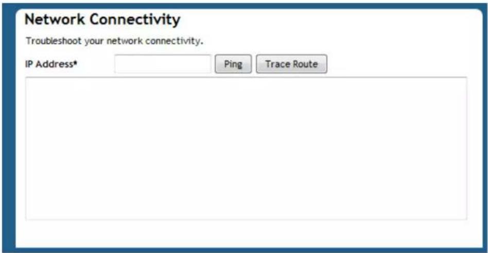
FIG. 49 Network Connectivity Tool
Using the Ping and Traceroute Tools
The Browser-Based Configuration Pages provide two commonly used tools that allow you to diagnose connectivity issues while managing the NXA-WAPZD1000 without having to exit the UI. The Ping and Traceroute tools can be accessed from anywhere in the UI that you see the icon.
For example, from the Dashboard, if the Currently Managed APs widget is open, click the icon next to an AP to launch the troubleshooting window. When the Network Connectivity window (FIG. 50) opens, click Ping to ping the IP address or Trace Route to diagnose the number of hops to the IP address.
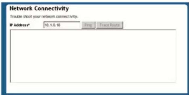
FIG. 50
You can also access the Ping and Traceroute tools by clicking the troubleshooting icon for an AP or client on the Monitor > Access Points and Monitor > Currently Active Clients pages, or via the Toolbox drop-down menu available from any section of the Browser-Based Configuration Pages.
Real Time Monitoring
The Real Time Monitoring tool provides a convenient at-a-glance overview of performance statistics such as CPU and memory utilization, number of APs and clients on the network, and number of packets transmitted. To view the Real Time Monitoring page, locate the Toolbox link at the top of the page and select Real Time Monitoring from the pull-down menu. You can also access the Real Time Monitoring page from the Monitor >Real Time Monitoring tab (page 42).
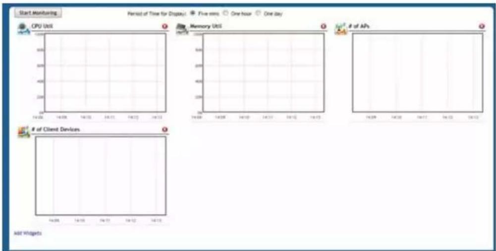
FIG. 51 Real Time Monitoring Tool
Blocking Client Devices
When users log into an NXA-WAPZD1000 network, their client devices are recorded and tracked. If, for any reason, you need to block a client device from network use, you can do so from the Browser-Based Configuration Pages. The following subtopics describe various tasks that you can perform to monitor, block and track client devices.
Monitoring Client Devices
- Go to the Dashboard (page 20), if it's not already in view.
- Under Devices Overview, look at # of Client Devices. If this widget has been hidden, click the Add Widgets link and select it from the toolbar.
- Click the current number, which is also a link. The Currently Active Clients page on the Monitor tab (page 33) appears, showing the first 15 clients that are currently connected to the NXA-WAPZD1000. If there are more than 15 currently active clients, the Show More button at the bottom of the page will be active. To display more clients in the list, click Show More. When all active clients are displayed on the page, the Show More button disappears.
- To block any listed client devices, follow the next set of steps.
Temporarily Disconnecting Specific Client Devices
Follow these steps to temporarily disconnect a client device from your WLAN. (The user can simply reconnect manually, if they prefer.) This is helpful as a troubleshooting tip for problematic network connections.
- Look at the Status column to identify any "Unauthorized" users.
- Click the Delete button in the Action column in a specific user row.
- The entry is deleted from the Active/Current Client list, and the listed device is disconnected from your WLAN.
Permanently Blocking Specific Client Devices
Follow these steps to permanently block a client device from WLAN connections.
- Look at the Status column to identify any unauthorized users.
- Click the Block button in the Action column in a specific user row.
- The status is changed to Blocked. This will prevent the listed device (and its user) from using your WLAN.
Reviewing a List of Previously Blocked Clients
- Go to Configure > Access Controls.
- Review the Blocked Clients table.
- You can unblock any listed MAC address by clicking the Unblock button for that address.
Blocking Client Devices
Deploying a Smart Mesh Network
Overview of Smart Mesh Networking
A Smart Mesh network is a peer-to-peer, multi-hop wireless network wherein participant nodes cooperate to route packets. In a Ruckus wireless mesh network, the routing nodes (that is, the Ruckus Wireless APs forming the network), or "mesh nodes," form the network's backbone. Clients (for example, laptops and other mobile devices) connect to the mesh nodes and use the backbone to communicate with one another, and, if permitted, with nodes on the Internet. The mesh network enables clients to reach other systems by creating a path that 'hops' between nodes.
Smart Mesh networking offers many advantages:
- Smart Mesh networks are self-healing: If any one of the nodes fails, the nodes note the blockage and re-route data.
- Smart Mesh networks are self-organizing: When a new node appears, it becomes assimilated into the mesh network.
In the Ruckus Wireless Smart Mesh network, all traffic going through the mesh links is encrypted. A passphrase is shared between mesh nodes to securely pass traffic.
When deployed as a mesh network, Ruckus Wireless APs communicate with the NXA-WAPZD1000 through a wired LAN connection or through wireless LAN connection with other access points.
Smart Mesh Networking Terms
Before you begin deploying your Smart Mesh network, getting familiar with the following terms that are used in this document to describe wireless mesh networks is recommended.
| Smart Mesh Networking Terms | |
| Term: Definition: | |
| Mesh Node A Ruckus Wireless Zone | eFlex AP with mesh capability enabled. |
| Root AP (Root Access Point) A mesh node communicating to an NXA-WAPZD1000 through its Ethernet (that is, wired) interface. | |
| Mesh AP (Mesh Access Point) A mesh node communicating to an NXA-WAPZD1000 through its wireless interface. | |
| eMAP (Ethernet Mesh AP) An eMAP is a mesh node that is connected to its uplink AP through a wired Ethernet cable, rather than wirelessly. eMAP nodes are used to bridge wireless LAN segments together. | |
| Mesh Tree Each Mesh AP has exactly one uplink to another Mesh AP or Root AP.Each Mesh AP or Root AP could have multiple Mesh APs connecting to it. Thus, the resulting topology is a tree-like topology. There is no limit to the number of trees in a mesh.A single NXA-WAPZD1000 can manage more than one mesh tree. The only limitation on how many mesh trees it can manage is dependent on the number of APs an NXA-WAPZD1000 can manage. For example, an NXA-WAPZD1000 1006 can manage a mesh tree of 6 APs or two mesh trees of 3 APs each. | |
| Hop The number of wireless mesh links a data packet takes from one MeshAP to the Root AP. For example, if the Root AP is the uplink of Mesh AP 1, then Mesh AP 1 is one hop away from the Root AP. In the same scenario, if Mesh AP 1 is the uplink of Mesh AP 2, then Mesh AP 2 is two hops away from the Root AP. A maximum of 8 hops is supported. | |
Supported Mesh Topologies
Smart Mesh networks can be deployed in three types of topologies:
- Standard Topology
- Wireless Bridge Topology
- Hybrid Mesh Topology
Standard Topology
The standard Smart Mesh topology consists of an NXA-WAPZD1000 and a number of Root APs and Mesh APs. In this topology, the NXA-WAPZD1000 and the upstream router are connected to the same wired LAN segment. You can extend the reach of your wireless network by forming and connecting multiple mesh trees (FIG. 52) to the wired LAN segment. In this topology, all APs connected to the wired LAN are considered "Root APs," and any AP not connected to the wired LAN is considered a "Mesh AP."
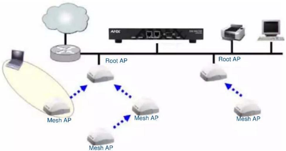
flowchart
graph TD
    A["Router"] -->|Root AP| B["Switch"]
    B -->|Root AP| C["Server"]
    C -->|Root AP| D["Computer"]
    A -->|Mesh AP| E["Switch"]
    E -->|Mesh AP| F["Switch"]
    E -->|Mesh AP| G["Switch"]
    E -->|Mesh AP| H["Switch"]
    E -->|Mesh AP| I["Switch"]
    style A fill:#f9f,stroke:#333
    style B fill:#ccf,stroke:#333
    style C fill:#cfc,stroke:#333
    style D fill:#fcc,stroke:#333
    style E fill:#cff,stroke:#333
    style F fill:#ffc,stroke:#333
    style G fill:#ffc,stroke:#333
    style H fill:#ffc,stroke:#333
    style I fill:#ffc,stroke:#333
FIG. 52 Mesh - Standard Topology
Wireless Bridge Topology
If you need to bridge isolated wired LAN segments, you can set up a mesh network using the wireless bridge topology. In this topology, the NXA-WAPZD1000 and the upstream router are on the primary wired LAN segment, and another isolated wired segment exists that needs to be bridged to the primary LAN segment. You can bridge these two wired LAN segments by forming a wireless mesh link between the two wired segments (FIG. 53).
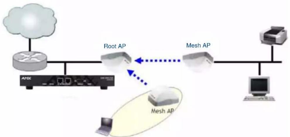
flowchart
graph TD
    A["Cloud"] --> B["Router"]
    B --> C["APX"]
    B --> D["Router"]
    D --> E["Mesh AP"]
    E --> F["Computer"]
    E --> G["Mesh AP"]
    G --> H["Router"]
    style A fill:#f9f,stroke:#333
    style B fill:#ccf,stroke:#333
    style C fill:#cfc,stroke:#333
    style D fill:#fcc,stroke:#333
    style E fill:#cff,stroke:#333
    style F fill:#ffc,stroke:#333
    style G fill:#cfc,stroke:#333
    style H fill:#fcc,stroke:#333
FIG. 53 Mesh - Wireless Bridge Topology
Hybrid Mesh Topology
A third type of network topology can be configured using the Hybrid Mesh concept. Ethernet-connected Mesh APs (cMAP) enable the extension of wireless mesh functionality to a wired LAN segment. An eMAP is a special kind of Mesh AP that uses a wired Ethernet link as its uplink rather than wireless. An eMAP is not considered a Root AP, despite the fact that it discovers the NXA-WAPZD1000 through its Ethernet port. Multiple eMAPs can be connected to a single Mesh AP to, for example, bridge a wired LAN segment inside a building to a wireless mesh outdoors.
In designing a mesh network, connecting an eMAP to a Mesh AP extends the Smart Mesh network without expending a wireless hop, and can be set on a different channel to take advantage of spectrum reuse.
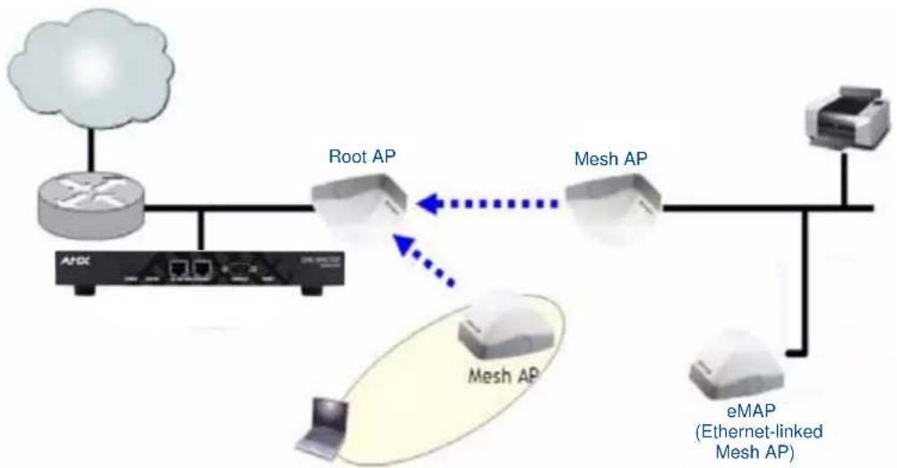
flowchart
graph LR
    A["Router"] --> B["Root AP"]
    B <--> C["Mesh AP"]
    C <--> D["eMAP (Ethernet-linked Mesh AP)"]
    D --> E["Printer"]
    B <--> F["Desktop"]
    C <--> G["Desktop"]
    style A fill:#f9f,stroke:#333
    style B fill:#ccf,stroke:#333
    style C fill:#ccf,stroke:#333
    style D fill:#cfc,stroke:#333
    style E fill:#fcc,stroke:#333
FIG. 54 eMAP - Hybrid Mesh Topology
Use the Monitor > Mesh page (page 41) to see a tree diagram of your Smart Mesh network.
| Mesh View Icons | |
| Icon: Meaning: | |
 | Root AP (RAP) |
 | Mesh AP (MAP) |
 | eMesh AP (eMAP) |
You can also view the role of any AP in your mesh network from the Monitor > Access Points page (page 66)
Deploying a Wireless Mesh via the NXA-WAPZD1000
Deploying a wireless mesh via an NXA-WAPZD1000 involves the following steps:
- Step 1: Prepare for Wireless Mesh Deployment
- Step 2: Enable Mesh Capability on the NXA-WAPZD1000
- Step 3: Provision and Deploy Mesh Nodes
- Step 4: Verify That the Wireless Mesh Network Is Up
Step 1: Prepare for Wireless Mesh Deployment
Before starting with your wireless mesh deployment, performing a number of tasks that can help ensure a smooth deployment is highly recommended.
- Ensure that the APs that will form the mesh are of the same radio type. - 802.11g APs can only mesh with other 11g APs.
- Single band 11n APs can only mesh with other single band 11n APs.
- Dual band 11n APs can only mesh with other dual band 11n APs.
- Plan Your Wireless Mesh Network - Survey your deployment site, decide on the number of APs that you will deploy (including the number of Root APs and Mesh APs), and then create a simple sketch of where you will deploy each Root AP and Mesh AP. Remember that Root APs need to be connected to the NXA-WAPZD1000 via their Ethernet ports. Make sure that the Root AP locations can be wired easily, if cabling is not yet available.
- Make Sure That Your Access Points Support Mesh Networking - Verify that the access points that you are planning to include in your wireless mesh network all provide mesh capability. Note that only firmware versions 6.0.0.0.* and later (for both the NXA-WAP1000 and the NXA-WAPZD1000) support mesh networking.
- Enable Auto Approval - If you do not want to have to manually approve the join requests from each mesh AP when they start forming the wireless mesh, you can enable Auto Approval. For instructions on how to enable Auto Approval, please refer to the Adding New Access Points to the WLAN section on page 69.
Step 2: Enable Mesh Capability on the NXA-WAPZD1000
If you did not enable mesh capability on the NXA-WAPZD1000 when you completed the Setup Wizard, you can enable it on the Configure > Mesh screen (page 95).
Step 3: Provision and Deploy Mesh Nodes
In this step, you will connect each AP to the same wired network as the NXA-WAPZD1000 to provision it with mesh-related settings. After you complete provisioning an AP, you must reboot it for the mesh-related settings to take effect.
To provision and deploy a mesh node:
-
Using one of the AP's Ethernet ports, connect it to the same wired network to which the NXA-WAPZD1000 is connected, and then power it on. The AP detects the NXA-WAPZD1000 and sends a join request.
-
If Auto Approval is enabled, continue to Step 3. If Auto Approval is disabled, log into the NXA-WAPZD1000, check the list of currently active access points for the AP that you are attempting to provision, and then click the corresponding Allow link to approve the join request. For detailed procedures on approving join requests, please refer to the Verifying/Approving New APs section on page 69.
-
After the AP has been provisioned, disconnect it from the wired network, unplug the power cable, and then move the device to its deployment location.
- If you want the AP to be a Root AP, reconnect it to the wired network using one of its Ethernet ports, and then power it on. When the AP detects the NXA-WAPZD1000 again through its Ethernet port, it will set itself as a Root AP, and then it will start accepting mesh association requests from Mesh APs.
- If you want the AP to be a Mesh AP, power it on but do not reconnect it to the wired network. When it does not detect the NXA-WAPZD1000 through its Ethernet port within 90 seconds, it will search for other Root APs or Mesh APs and, once mesh neighbor relationships are established, form a mesh tree.

After an AP in its factory default state has been provisioned, you need to reboot it to enable mesh capability.
Repeat Steps 1 to 3 for each AP that you want to be part of your wireless mesh network. After you complete provisioning and deploying all mesh nodes, verify that the wireless mesh has been set up successfully.
Step 4: Verify That the Wireless Mesh Network Is Up
After you complete deploying all mesh nodes to their locations on the network, you can check the Map View on the Browser-Based Configuration Pages to verify that mesh associations have been established and mesh trees formed.
- In the Browser-Based Configuration Pages, select Monitor >Map View. The Map View appears and shows the mesh nodes that are currently active. (For instructions on importing a map, please refer to the Importing a Floorplan Image section on page 77.)
- Check if all the mesh nodes that you have provisioned and deployed appear on the Map View.
- Verify that a mesh network has been formed by checking if dotted lines appear between the mesh nodes (FIG. 55). These dotted lines identify the neighbor relationships that have been established in the current mesh network.

If your mesh spans multiple NXA-WAPZD1000s, it is possible for a node to be associated to a different device than its parent or children.
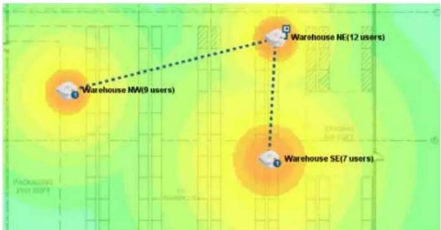
FIG. 55 Neighbor relationships in a mesh network
The symbols next to the AP icons indicate whether the AP is a Root AP, Mesh AP or eMAP. Refer to the following table:
| Map View AP Icons | |
| Icon: Meaning: | |
 | An AP with the upward pointing arrow is a Root AP. |
 | An AP with a number in a circle is a Mesh AP. The number indicates the number of hops from the mesh AP to the Root AP. |
 | An AP with a dimmed blue square indicates that it is a Root AP without any active downlinks. |
 | An AP with a red square is an Ethernet-Linked Mesh AP (eMAP). |
 | An AP with an X icon is disconnected. |
Using the ZoneFlex LEDs to Determine the Mesh Status
In addition to checking the mesh status of ZoneFlex APs from the Browser-Based Configuration Pages, you can also check the LEDs on the APs. The LED behaviors that indicate the AP's mesh status vary depending whether the AP is a single-band or a dual-band model.
WLAN LED
When Smart Mesh is enabled, the behavior of the WLAN LED indicates uplink status. Refer to the table below for a complete list of possible LED colors and behaviors for Root APs and Mesh APs, and the mesh status that they indicate.
| WLAN LED Behavior | |
| LED Color/Behavior: Root AP | / Mesh AP / eMAP |
| Solid green No mesh downlink, and; | At least one client is associated with the AP. |
| Solid amber No mesh downlink, and; | No client is associated with the AP. |
| Fast blinking green At least one mesh downlink exists, and; | At least one client is associated with the AP. |
| Slow blinking green At least one mesh downlink exists, and; | No client is associated with the AP. |
Signal/Air Quality LED
| Signal/Air Quality LED Behavior | ||
| LED Color/Behavior: Root AP | /eMAP: Mesh AP: | |
| Solid green N/A • Connected to a Root AP or | another Mesh AP• Signal quality is good | |
| Fast blinking green N/A • Connected to a Root AP or | another Mesh AP• Signal quality is fair or poor | |
| Slow blinking green N/A The AP is searching for an uplink | ||
| Off This is a Root AP or eMAP N/A | ||
5G LED
| 5G LED Behavior | ||
| LED Color/Behavior: Root AP | /eMAP: Mesh AP: | |
| Fast blinking green No Mesh AP is | connected Disconnected from the Root AP | |
| Solid green • At least one Mesh AP | isconnected• Signal quality is good | • Connected to a Root AP• Signal quality is good |
| Solid amber • At least one Mesh AP | isconnected• Signal quality is fair | • Connected to a Root AP• Signal quality is fair |
Understanding Mesh-related AP Statuses
In addition to using the Map View to monitor the status of the mesh network, you can also check the Monitor > Access Points page for mesh-related AP statuses. The table below lists all possible AP statuses that are related to mesh networking, including any actions that you may need to perform to resolve mesh-related issues.
| Mesh-Related AP Status | ||
| Status: Description | Recommended Action: | |
| Connected AP is connected to the NXA-WAPZD1000, but mesh is disabled | If mesh is enabled on the AP, you may need to reboot it to activate the mesh. | |
| Connected (Root AP) AP is connected to the NXA-WAPZD1000 via its Ethernet port | ||
| Connected (Mesh AP, n hops) | AP is connected to the NXA-WAPZD1000 via its wireless interface and is n hops away from the Root AP. | |
| Connected (eMesh AP, n hops) | AP is connected to the NXA-WAPZD1000 via its Ethernet port, but acts as a Mesh AP using another Mesh AP as its uplink. | |
| Isolated Mesh AP AP is disconnected from the NXA-WAPZD1000 mesh | The AP may be configured incorrectly. Verify that the mesh SSID and passphrase configured on the AP are correct.If Uplink Selection is set to Manual, the uplink AP specified for this AP may be off or unavailable. | |
Using Action Icons to Configure and Troubleshoot APs in a Mesh
The following action icons are used to perform configuration and troubleshooting tasks on the respective AP. The icons are displayed next to APs in the Currently Managed APs table on the Dashboard. Some of the same action icons are also available on other pages including Monitor > Access Points (page 24) and Monitor > Mesh (page 41).
| Action Icons | ||
| Icon: Icon Name: Action: | ||
 | System Info Generate a log file (support.txt) containing system information on this AP | |
 | Configure | Go to the Configure > Access Points page and edit the configuration settings for this AP. |
 | Mesh View Open a “Mesh View” screen with this AP highlighted in a Mesh tree that also shows the uplink and downlink APs connected to this AP. | |
 | SpeedFlex Launch the SpeedFlex performance test tool to measure uplink/downlink speeds to/from this AP. | |
 | Troubleshoot | Troubleshoot connectivity issues using Ping and Traceroute. |
| Action Icons (Cont.) | ||
 | Restart Initiate | a reboot of this AP. |
| [×KC8] | Recover Recover | an isolated Mesh AP. |
 | Allow Allow this | AP to be managed by the NXA-WAPZD1000. This icon will only appear if you have disabled automatic approval under “Access Point Policies” on the Configure > Access Points page. |
 | RF Info Generates | a log file called info.txt, containing radio frequency data that can be used for troubleshooting the RF environment. |
Setting Mesh Uplinks Manually
In a wireless mesh network, the default behavior of Mesh APs is to connect automatically to a mesh node (either Mesh AP or Root AP) that provides the highest throughput. This automatic connection is called Smart Uplink Selection.
If you want to shape your mesh network or force a certain topology, you will need to disable Smart Uplink Selection and manually set the mesh nodes to which an AP can connect. Note that in most situations, Manually changing the roles of APs in a mesh is not recommended, because it can result in isolated Mesh APs.

Do not manually set a Mesh AP as a Root AP. Only APs that are connected to the NXA-WAPZD1000 via Ethernet (and on the same LAN segment) should be configured as Root APs. Misconfiguring a Mesh AP or an eMAP as a Root AP can cause the AP to become isolated, or, in the case of eMAP, can result in a network loop.
To set the mesh uplink for an AP manually:
- From the Browser-Based Configuration Pages, select Configure > Access Points (page 66).
- In the Access Points table, find the AP you want to restrict, and click Edit under the Actions column. The editing form appears below your selection.
- Under Advanced Options > Uplink Selection, select the Manual radio button. The other APs in the mesh appear below the selection.
- Select the check box for each AP that the current AP can use as uplink.

If you set Uplink Selection for an AP to Manual and the uplink AP that you selected is off or unavailable, the AP status on the Monitor > Access Points page will appear as Isolated Mesh AP.
- Click OK to save your settings.
Troubleshooting Isolated Mesh APs
Isolated Mesh APs are those that were once managed by the NXA-WAPZD1000 but are now unreachable. They are up and running and constantly searching for mesh uplinks, but are unable to connect to any root AP. You can check if you have any isolated mesh APs on the network by checking the Monitor > Access Points page.

A mesh network is dynamic in nature. Before attempting to resolve any mesh-related issue, please wait 15 minutes to allow the mesh network to stabilize. Some mesh related issues are automatically resolved once the mesh network stabilizes.
Understanding Isolated Mesh AP Statuses
There are five possible reasons for a mesh AP to become isolated. The table below lists all possible Isolated Mesh AP statuses that may appear on the Monitor > Access Points page, and provides possible reasons for the isolation and the recommended steps for resolving the issue.
| Isolated Mesh AP statuses | |
| Status: Possible Reason: | |
| No APs within hop-limit | The AP cannot find other APs within the internally defined limit to the number of hops. The hop limit mechanism helps ensure that mesh APs maintain reasonable network performance.To resolve this, add additional Root APs near this isolated Mesh AP. |
| Searching for uplinks The AP is still | searching for uplinks. This is usually a temporary state and is typically resolved automatically within 15 minutes as the mesh network stabilizes. If there is a significant number of APs on the network, it might take longer for the AP to resolve this. |
| Config error The AP attempted to e | establish the mesh uplink but was unsuccessful. If you recently updated the mesh SSID and passphrase, it is likely that your changes have not propagated correctly to this AP (for example, the AP was offline when you updated the mesh SSID and passphrase). |
| No APs with matching radio type | The AP is unable to find an uplink AP with the same radio type. Ruckus Wireless Smart Mesh APs must use the same radio type to be able connect to each other via the mesh network. For example, an 802.11n Mesh AP will only connect to another 802.11n AP, and an 802.11b/g Mesh AP will only connect to another 802.11b/g AP.To resolve this, place additional wired APs or Mesh APs that use the same radio type near this AP. |
Recovering an Isolated Mesh AP
To perform these procedures, you will need:
- A notebook computer with wireless capability. If you are running Windows XP on the computer, make sure that either the WPA2 patch or Service Pack 3 is installed.
- The last known mesh configuration for the AP (steps for obtaining this information are provided below).
- An SSH client, such as PuTTY or OpenSSH.
Step 1: Obtain the AP's Last Known Mesh Configuration
- From the Browser-Based Configuration Pages, select Monitor> Access Points.
-
Under Currently Managed APs, look for the status message Isolated Mesh AP (Config error), and then click the Recover icon on the same row. A page appears, which shows the AP's last known mesh configuration. Mesh information that appears on this page includes:
-
AP's MAC Address
-
Last Known Mesh SSID (mesh name)
● Last Known Mesh PSK (mesh passphrase) -
Write down these details on a piece of paper. You will need them later in the next procedure.
Step 2: Set Up Your Computer for Wireless Connection to the AP
- Assign the following static IP address settings to your computer:
IP Address: 192.168.54.34
- Mask: 255.255.255.252
-
Create a wireless network from your computer. If you are running Windows XP, you can use the Wireless Network Setup Wizard to create the wireless network. Configure the wireless network with the following settings:
-
Association mode: WPA2
- Encryption method: AES
- SSID: Type the AP's last known SSID (which you obtained in the previous section)
- PSK: Type the AP's last known PSK (which you obtained in the previous section)
Step 3: Connect to the AP and Update its ESSID and Passphrase
- After you create the wireless network, position the computer close enough to the AP to allow association.
- After your computer has associated with the AP, start the SSH client, and then connect to 192.168.54.33 (the AP's IP address).
- Log into the AP via SSH using the same user name and password that you use to log into the Browser-Based Configuration Pages.
- Enter the command set meshcfg ssid "current_ssid", where current_ssid is the SSID that the mesh network is currently using.
- Enter the command set meshcfg passphrase "current_passphrase", where current_passphrase is the passphrase or PSK that the mesh network is currently using.
- Close the SSH client.
You have completed recovering the isolated mesh AP. You should be able to manage this AP again shortly. Please wait at least 15 minutes (to allow the mesh network to stabilize), and then try managing this AP again via the NXA-WAPZD1000.
Smart Mesh Networking Best Practices
Choosing the Right AP Model for Your Mesh Network
The NXA-WAPZD1000 supports both 802.11g and the newer, faster 802.11n APs with which to form a mesh network. Because mesh throughput degrades with the number of hops, the best performance can be achieved using the newer, faster 802.11n APs. However, 802.11g APs will also form a suitable mesh network if your client devices do not support the newer 11n standard.
The most important point to note, however, is that the two technologies cannot be mixed in a mesh topology. All nodes in a mesh must be 802.11n or 802.11g. You cannot mix 802.11n with 802.11g APs in a mesh. Additionally, dual band 11n APs can only mesh with other dual band 11n APs, and single band 11n APs can only mesh with other single band 11n APs.
In summary, build your mesh network as follows:
- Ensure that all APs are dual band 802.11n
● Ensure that all APs are single band 802.11n - Ensure that all APs are 802.11g

The above restrictions apply only to AP-to-AP communication as part of a mesh, not to AP-to-client communication. For example, 802.11g clients can connect to an 802.11n mesh, and vice versa.
Calculating the Number of APs Required
This is an important step in planning your mesh network. In this step, you will calculate the number of total APs (Root APs and Mesh APs) that are needed to provide adequate coverage and performance for a given property. If you plan to support Internet grade connections for casual web browsing, plan for a design that delivers 1Mbps of throughput in the entire coverage area. For enterprise-grade connections, plan for 10Mbps of throughput.
WiFi is a shared medium, of course, so this aggregate bandwidth will be shared amongst the concurrent users at any given time. In other words, if the network is designed to support 10Mbps, it would support 1 user at 10Mbps, or 10 users at 1Mbps each. In reality, due to statistical multiplexing (just like the phone system - the fact that not all users are using the network concurrently), if you use an oversubscription ratio of 4:1, such a network could actually support 40 users at 1Mbps.
But first, some background on mesh technology, and its impact on performance. A Root AP (RAP) in a mesh network has all its wireless bandwidth available for downlink, because the uplink is wired. For mesh APs (MAPs), the available wireless bandwidth has to be shared between the uplink and the downlink. This degrades performance of a mesh AP as compared to a Root. With this background in mind, a two-step process to calculate the number of APs will be used.
Step 1
In step 1, we assume that all APs are Roots (i.e. have an Ethernet drop available), even if this is actually not the case. This is our most optimistic number - when all APs are connected by wire. The best way to do this is to use the handy calculator provided on the Big Dogs Partner Portal at
http://partners.ruckuswireless.com/sales_tools/quoting_guide

Note that eMAP APs are treated as Root APs for the purpose of calculating coverage requirements. Although an eMAP is actually a subset of Mesh AP, because the calculator does not distinguish between Root APs and eMAPs, for this calculation, you should treat them as Root APs.
A sampling of results generated by the calculator, for an environment with 25% Line of Sight/Cubicle, 50% dry wall and wood, and 25% concrete and tile, is shown below. This table is useful for some quick calculations on number of APs. However, it is recommended that you use the calculator on the Big Dogs Portal, so that your exact RF parameters and square feet can be entered for your particular site.
| Number of APs required (all Root) | ||
| Square Feet: # APs Needed | InternetGrade (Throughput 1Mbps): | # APs Needed Enterprise Grade (Throughput 10Mbps) |
| 10,000 4 5 | ||
| 20,000 4 6 | ||
| 50,000 5 11 | ||
| 100,000 9 20 | ||
| 200,000 15 39 | ||
Step 2
Once this ideal AP number (all Roots) is determined, it needs to be adjusted for mesh performance degradation. The mesh degradation depends heavily upon the number of APs that can be Roots - in other words the number of APs that can be cabled via Ethernet. The more APs that can be cabled as Roots, the more the performance resembles the ideal (best) case. The table below shows the AP Multiplier for a given RAP:MAP ratio.
| AP Multiplier to Account for Mesh | |
| RAP:MAP Ratio: AP Multiplier: | |
| 20% 1.8 | |
| 40% 1.6 | |
| 60% 1.5 | |
| 80% 1.3 | |
| 100% 1.0 | |
Once the AP multiplier is determined, the formula below is used to calculate the total number of APs required for the site.
Formula: Total Number of APs (RAPs and MAPs) Required = #APs x AP Multiplier
Using an example to calculate the number of APs for a mesh is useful:
EXAMPLE: Calculate the number of APs required for enterprise grade coverage (10Mbps throughput) in a 100,000 square feet coverage area that is 25% line of sight/ cubicle, 50% dry wall and wood, and 25% concrete and tile.
STEP 1: Use the calculator on the Big Dogs Portal or to calculate the ideal number of APs. From the Number of APs Required table = 20 APs
STEP 2: There are only 10 Ethernet drops available due to building considerations and some outdoor coverage requirements. Therefore the RAP:MAP ratio is 10:20, or 50%. Using the AP Multiplier to Account for Mesh table, because 50% is between 40% and 60%, the more conservative (higher is more conservative) AP Multiplier of 1.6 is chosen.
# of APs = 20 x 1.6 = 32 APs (10 RAP, and 22 MAP)
Placement and Layout Considerations
- Utilize two or more RAPs: To prevent having a single point-of-failure, it is always best to have 2 or more RAPs so that there are alternate paths back to the wired network. In the example above, the number of RAPs should be increased from 1 to 2 to meet this best practice.
- More roots are better: the more Roots in the design, the higher the performance. Therefore, as far as possible, try to wire as many APs as is convenient.
- Design for max 3 hops: Avoid an excessive number of hops in your mesh topology. In general, the goal should be to have the lowest number of hops, provided other considerations (like Signal >= 25%) are met. Limiting the number of hops to 3 or less is best practice.
- Place a Root towards the middle of a coverage area to minimize the # hops required to reach some MAPs.
- If there are multiple Roots, ensure that the Roots are distributed evenly throughout the coverage area (not clumped up close together in one area). Of course, the whole purpose of mesh is to
provide coverage in areas that are hard to wire, therefore the ideal may not be possible. Evenly spaced Root APs are preferable as far as is possible.
- If the customer's network utilizes a wireless backhaul technology for broadband access, it is recommended to not mount the broadband wireless modem right next to an AP. A distance of 10 feet or more would be desirable.
Signal Quality Verification
The above guidelines for planning will result in a well-designed mesh. However, it is advisable to place the APs in the planned locations temporarily using a tripod stand or other means, and actually checking the Signal Quality throughout the mesh network. In addition, once the mesh is deployed, the Signal Quality should be periodically monitored to make sure the mesh is operating optimally. Signal Quality is a measurement of the link quality of the MAP's uplink, and is available on the Browser-Based Configuration Pages.
To view the Signal parameter in the Browser-Based Configuration Pages:
- Go to Monitor > Access Points, and click on the Mesh AP being tested (click the MAC address) to see the Access Point detail screen (FIG. 7).
Two best practice observations should be met:
- Ensure Signal >= 25%: The Signal value under Neighbor APs that shows “Connected” should be 25% or better. If it is lower, you need to bring the AP closer, or move it to avoid an obstruction, such that the Signal value becomes 25% or better. For a more conservative design, you may use 35% as your Signal benchmark.
- Ensure Minimum 2 Uplink options for every MAP: In addition, under Neighbor APs, it is best practice that there exists an alternate path for this mesh uplink. This alternate path should also have a Signal of 25% or better. Stated differently, there should be at least 2 possible links that the MAP can use for uplink, and both should have a Signal value of 25% or better. For a more conservative design, you may use 35% as your Signal benchmark.
Mounting and Orientation of APs
ZoneFlex APs are very tolerant to a variety of mounting and orientation options due to Ruckus Wireless' use of its unique BeamFlex technology, in which the RF signal is dynamically concentrated and focused towards the other end of the RF link.
The bottom line regarding orientation and placement is that during the planning phase, it is advisable to use the Signal Quality as your benchmark., Ensure that the Signal is better than 25% for trouble-free operation.
For additional mounting details, please also consult the Quick Setup Guide and the Wall and Ceiling Mounting Instructions that came in the AP box.
Indoor APs - Typical Case: Horizontal Orientation
ZoneFlex indoor APs are typically oriented such that the top of the AP is pointing either straight up or straight down.
Indoor APs - Vertical Orientation
A less typical vertical orientation may be used in certain cases where it is not possible for mechanical or aesthetic reasons to use the typical orientation. In such cases, indoor APs may also be wall mounted vertically.
Outdoor APs - Typical Horizontal Orientation
Outdoor APs are typically mounted in a horizontal orientation. A less typical orientation would be vertically mounted.
Elevation of RAPs and MAPs
In addition to orientation, it is important to also pay attention to the elevation of an AP for reliable mesh operation. More specifically, large differences in elevation should be avoided. So whether you are deploying an indoor mesh, an outdoor mesh, or a mixed indoor-outdoor mesh, you should ensure that as far as convenient and possible, MAPs and RAPs should all be at a similar elevation from the ground. For example, for an indoor-outdoor mesh, if all your indoor RAPs and MAPs are at ceiling height (standard 15-foot ceiling), then you would not want to mount the outdoor MAPs on 40-foot poles. You would want to keep all MAPs and RAPs at around the same elevation from the ground.
Best Practice Checklist
Following the mesh best practices will ensure that your mesh is well-designed, and have the capacity and reliability required for your enterprise applications. The best practices are summarized below as a checklist for quick review.
- Do not mix 802.11n with 802.11g APs in your mesh. They will NOT mesh. Additionally, dual band 11n APs will not mesh with single band 11n APs. To ensure your APs will mesh with each other, ensure they are all of the same radio type: either all 802.11g, all 802.11n single band, or all 802.11n dual band APs.
- Using the formula and example provided, calculate the number of RAPs and MAPs required for your coverage area and bandwidth requirements.
- Ideally deploy two or more RAPs so there is an alternate path for reliability, even when capacity and coverage only require one RAP.
- Avoid an excessive number of hops. Ideally keep hop count to 3 or less.
- Having more Roots is better for performance.
- Place your Root towards the middle of a coverage area so as to minimize the number of hops to reach a given MAP.
- For multiple Roots, ensure that the Roots are distributed evenly throughout the coverage area.
- Once the APs are mounted on a test-basis or permanently, use the Signal quality measurement to ensure that the Connected MAP uplink is 25% or better.
- Ideally there should be at least one alternate uplink path for every MAP, and the signal quality of that alternate path should also be 25% or better.
Smart Mesh Networking Best Practices
Troubleshooting
Troubleshooting Failed User Logins
SUMMARY: This troubleshooting topic addresses the problems that network users might have with configuring their client devices and logging into your WLAN.
Upon the completion of the Setup Wizard, the NXA-WAPZD1000 automatically activates a default internal WLAN for authorized users. A key benefit of the internal WLAN is the Zero-IT configuration, which enables new users to self-activate their wireless client devices with little or no assistance from the IT department. Zero-IT client device configuration requires the client be running Windows XP (SP2 or later), Vista (SP1 or later), Windows 7, Mac OS X, iPhone or iTouch and using a wireless network adapter that implements WPA.
If you and your WLAN users run into initial connection failures when using the Zero-IT configuration and login, almost all of the problems have two key causes:
- Your users' client devices are running another OS, or running a version of Windows pre-XP/ SP2. (This includes XP/SP1.)
- Your users' client devices are using wireless network adapters without a WPA implementation.
The following list of options may be applicable based on your client system's qualifications:
- Option 1: If Windows XP SP2/Vista/7 is on the client machine, check the wireless network adapter to verify the implementation of WPA.
- Option 2: Upgrade to Windows XP SP2/Vista/7, and if needed, acquire a wireless network adapter with WPA support. Once these changes are made, your users can attempt Zero-IT activation again.
- \Option 3: If an older version of Windows is in use, or if another OS is being used, the user must manually enter the Ruckus WPA passphrase in their network configuration (for more information, please refer to the Authenticating Clients that Do Not Support Zero-IT section on page 64).
- Option 4: If the client's OS cannot be upgraded and the wireless adapter is limited to WEP, you will need to do the following:
- Create an additional WLAN for non-standard client connections, then create a Role that refers to this WLAN, and assign that role to the relevant user accounts.
- Enter the WEP key in the network configuration on the client device.
Fixing User Connections
If any of your users report problematic connections to the WLAN, the following debugging technique may prove helpful. Basically, you will be deleting that user's client from the Active Clients table in the NXA-WAPZD1000, and when their client connection automatically renews itself, any previous problems will hopefully be resolved.
To fix the connection of an active client:
- In the Browser-Based Configuration Pages, go to Monitor > Currently Active Clients.
- In the Clients table, locate the problematic client, and click the Delete button on the same row.
- The client will be immediately disconnected from the WLAN. (Be sure not to block the client. If you do accidentally block a client, go to Configure > Access Control to unblock.)
- From the client computer, refresh the list of wireless networks and attempt to log in again.
- After one to two minutes, the Clients table will refresh and display the client again.
If WLAN Connection Problems Persist
If the previous technique fails to resolve the connection issues, you may need to guide the user through a reset of their WLAN configuration. This requires deleting the user record, then creating a new user record, after which the user must repeat the Zero-IT Activation process to reactivate their device with the NXA-WAPZD1000.
- Have the user log out of the WLAN.
-
In the Browser-Based Configuration Pages, go to Configure > Users. The Internal User Database table appears, displaying a list of current user accounts.
-
Locate the problematic user account in the table, and click the check box to the left of the user's name.
- Click Delete.
- Click the Create New button to create a new user account for this user. Enter a user name and password, and choose a role from the drop-down menu.
- Send a notification to the user with instructions on how to re-configure their client and log into the WLAN again.
At the end of this process, the user should be reconnected. If problems persist, they may originate in Windows or in the wireless network adapter.
Measuring Wireless Network Throughput with SpeedFlex
SpeedFlex is a wireless performance tool included in the NXA-WAPZD1000 that you can use to measure the downlink throughput between the NXA-WAPZD1000 and a wireless client, the NXA-WAPZD1000 and an AP, and a wireless client and an AP. When performing a site survey, you can use SpeedFlex to help find the optimum location for APs on the network with respect to user locations.

Before running SpeedFlex, verify that the Guest Usage and Wireless Client Isolation options (on the Configure > WLANs > Editing {WLAN Name} page) are disabled. The SpeedFlex Wireless Performance tool may not function properly when either or both of these options are enabled. For example, SpeedFlex may be inaccessible to users at http://{zonedirector-ip-address}/perf or SpeedFlex may prompt you to install the Speed-Flex application on the target client, even when it is already installed.

The following procedure describes how to run SpeedFlex from the Browser-Based Configuration Pages to measure a wireless client's throughput.
To measure the throughput of an AP or a client from the Browser-Based Configuration Pages:
- Find out the MAC address of the AP or wireless client that you want to use for this test procedure.
- If you are testing client throughput, verify that the wireless client is associated with the AP that you want to test.
- Log in to the Browser-Based Configuration Pages. You can use the wireless client that you are testing or another computer to log in to the Configuration Pages.
- If you want to test AP throughput, click Monitor > Access Points. If you want to test client throughput, click Monitor > Currently Active Clients.
- In the list of APs or clients, look for the MAC address of the AP or wireless client that you want to test, and then click the SpeedFlex link on the same row. The SpeedFlex Wireless Performance Test interface loads, showing a speedometer and the IP address of the AP or client that you want to test.
If the NXA-WAPZD1000 is unable to determine the IP address of the wireless client that you want to test (for example, if the wireless client is using a static IP address), the SpeedFlex link for that client does not appear on the Currently Active Clients page.
-
If you are testing AP throughput, you have the option to test both Downlink and Uplink throughput. Both options are selected by default. If you only want to test one of them, clear the check box for the option that you do not want to test.
-
Click the Start button.
- If the target client does not have SpeedFlex installed, a message appears in the NXA-WAPZD1000 administrator's browser, informing you that the SpeedFlex tool has to be installed and running on the client before the wireless performance test can continue. Click the OK button on the message, download the appropriate SpeedFlex version (Windows or Mac) from http://

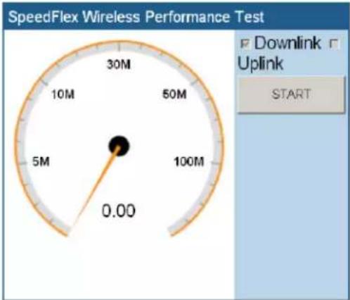
gauge
SpeedFlex Wireless Performance Test | Measurement | Value | | :--- | :--- | | 30M | 30 | | 10M | 50 | | 5M | 5 | | 100M | 100 | | 0.00 | 0.00 | Downlink Uplink STARTClient IP: 10.1.0.11
FIG. 56 SpeedFlex interface
A progress bar appears below the speedometer as SpeedFlex generates traffic to measure the downlink or uplink throughput. One throughput test typically runs for 10-30 seconds. If you're testing AP throughput and you selected both Downlink and Uplink options, both tests should take about one minute to complete.
When the tests are complete, the results appear below the Start button. Information that is shown includes the downlink/uplink throughput and the packet loss percentage during the tests.
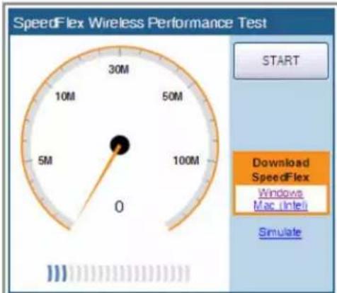
Client IP: 172.17.16.58
FIG. 57 Click the download link for the target client's operating system
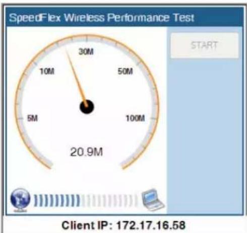
gauge
SpeedFlex Wireless Performance Test | Value | |---| | 30M | | 10M | | 50M | | 5M | | 100M | | 20.9M | Client IP: 172.17.16.58FIG. 58 A progress bar appears as SpeedFlex measures the wireless throughput
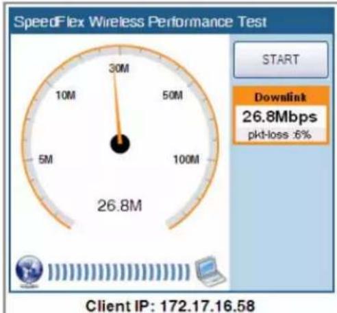
gauge
SpeedFlex Wireless Performance Test | Measurement | Value | | :--- | :--- | | 30M | | 10M | | 50M | | 100M | | 26.8M | Start Downlink 26.8Mbps pkt-loss:6% Client IP: 172.17.16.58FIG. 59 When the test is complete, the tool shows the downlink throughput and packet loss percentage
Using SpeedFlex in a Multi-Hop Smart Mesh Network
SpeedFlex can also be used to measure multi-hop throughput between APs and the NXA-WAPZD1000 in a mesh tree. For example, if you have a mesh tree that is three hops deep (i.e., NXA-WAPZD1000... Root AP... Mesh AP 1... Mesh AP 2), SpeedFlex can measure the total throughput between the NXA-WAPZD1000 and Mesh AP 2. Running the Multi-Hop SpeedFlex tool returns throughput results for each hop, as well as the aggregate throughput from NXA-WAPZD1000 to the final AP in the tree.
To measure throughput across multiple hops in a Smart Mesh tree:
- In the Browser-Based Configuration Pages, go to Monitor > Mesh, or open the Mesh Topology widget on the Dashboard.
-
Locate the AP whose throughput you want to measure, and click the SpeedFlex icon on the same row as that AP. The SpeedFlex icon changes to an icon with a green check mark, and the Multi-Hops SpeedFlex button appears.
-
Click Multi-Hops SpeedFlex. The SpeedFlex utility launches in a new browser window (FIG. 60).
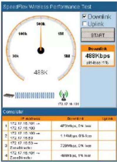
FIG. 60 Multi-Hop SpeedFlex test results
- Select Uplink, Downlink or both (default is both), and click Start to begin. Note that multihop SpeedFlex takes considerably longer to complete than a single hop. If you want to complete the test faster, deselect either Uplink or Downlink and test one direction at a time.
Allowing Users to Measure Their Own Wireless Throughput
The NXA-WAPZD1000 provides another version of the SpeedFlex Wireless Performance Test application that does not require authentication. This version can be accessed at:
http://{zonedirector-ip-address}/perf
If you want wireless users to be able to measure their own wireless throughput, you can provide this link to them, along with the instructions below. Before sending out these instructions, remember to replace the {zonedirector-ip-address} variable with the actual NXA-WAPZD1000 IP address.
How to Measure the Speed of Your Wireless Connection
The following instructions describe how you can use SpeedFlex to measure the speed of your wireless connection to your access point.
-
Make sure that your wireless device is connected only to the wireless network. If your wireless device is also connected to the wired network, unplug the network cable.
-
Start your Web browser, and then enter the following in the address or location bar: http://{zonedirector-ip-address}/perf
The SpeedFlex Wireless Performance Tool interface loads in your browser.
- Click the Start button. The following message appears:
Your computer does not have SpeedFlex running. Click the OK button, download the SpeedFlex application for your operating system, and then double-click SpeedFlex.exe to start the application.
When SpeedFlex is running on your computer, click Start again to continue with the wireless performance test.
-
Click OK. Windows and Mac (Intel) download links for SpeedFlex appear on the SpeedFlex Wireless Performance Test interface (FIG. 57).
-
Click the SpeedFlex version that is appropriate for your operating system, download the SpeedFlex file, and then save it to your computer's hard drive.
-
After downloading the SpeedFlex file, locate the file, and then double-click the file to start the application. A command prompt window appears and shows the following message:
Entering infinite loop. Enjoy the ride.
This indicates that SpeedFlex was successfully started. Keep the command prompt window open.
- On the SpeedFlex Wireless Performance Test interface, click the Start button again. A progress bar appears below the speedometer as the tool generates traffic to measure the downlink throughput from the AP to the client. The test typically runs from 10 to 30 seconds.
When the test is complete, the results appear below the Start button. Information that is shown includes the downlink throughput (in Mbps) between your wireless device and the AP, as well as the packet loss percentage during the test.
If the packet loss percentage is high (which indicates poor wireless connection), try moving your wireless device to another location, and then run the tool again. Alternatively, contact your network administrator for assistance.
Diagnosing Poor Network Performance
You can try the following diagnostic and troubleshooting techniques to resolve poor network performance.
- From the Browser-Based Configuration Pages, go to Monitor > Map View.
- Look on the map for rogue APs. If there is a large number, and they belong to neighboring networks, proceed to the next task.
- Go to Configure > Access Points.
- Edit each AP record, to assign each device a channel that will not interfere with other APs. For example, if you have three Ruckus APs, open the Radio B/G Channel drop-down list in each AP record and choose "1", "6" and "11" in each of the three. However many APs you have, make sure that each AP has a fixed channel number not too close to the number of a nearby Ruckus AP.
Starting a Radio Frequency Scan
This task complements the automatic RF scanning feature that is built into the NXA-WAPZD1000 That automatic scan assesses one radio frequency at a time, every 20 seconds or so.
To manually start a complete radio frequency scan that assesses all possible frequencies in all devices at one time:
- In the Browser-Based Configuration Pages, go to Administer > Diagnostics.
- When the Diagnostics page appears, look for the Manual Scan options, and then click Scan.

This operation will interrupt active network connections for all current users.
- Open the Dashboard or go to Monitor >Map View to review the scanning results. This will include rogue device detection, and an updated coverage evaluation.
Troubleshooting
AMX UNIVERSITY
Increase Your Revenue through education + knowledge
In the ever-changing AV industry, continual education is key to success. AMX University is dedicated to ensuring that you have the opportunity to gather the information and experience you need to deliver strong AMX solutions. Plus, AMX courses also help you earn CEDIA, NSCA, InfoComm, and AMX continuing education units (CEUs).
Visit AMX University online for 24/7/365 access to:
- Schedules and registration for any AMX University course
- Travel and hotel information
- Your individual certification requirements and progress

- Operation/Reference Guide
- NXA-WAPZD1000
- ZoneDirector Smart WLAN Controller
- AMX Limited Warranty and Disclaimer
- AMX Software License and Warranty Agreement
- Table of Contents
- Introduction 9
- Installation and Setup 13
- Browser-Based Configuration Pages 19
- Dashboard 20
- Monitor Tab 23
- Blocking Client Devices 125
- Deploying a Smart Mesh Network 127
- Smart Mesh Networking Best Practices ....138
- Troubleshooting 143
- Introduction
- NXA-WAPZD1000 ZoneDirector Smart WLAN Controller
- Overview
- Common Applications
- Features
- Power Adapter Compatibility
- Installation and Setup
- Powering the NXA-WAPZD1000
- Resetting the NXA-WAPZD1000
- Configuring the NXA-WAPZD1000
- Working with the Setup Wizard
- Connecting NXA-WAP1000s to your local area Ethernet network
- Accessing the NXA-WAPZD1000's Command Line Interface
- About Wireless WLAN Security
- Enabling Smart Redundancy
- Configuring the NXA-WAPZD1000 for Smart Redundancy
- Forcing Failover to the Backup NXA-WAPZD1000
- Browser-Based Configuration Pages
- Dashboard
- of APs: 1
- of Client Devices: 2
- of Rogue Devices: 7
- of Rogue Devices: 7 18
- Dashboard Widgets
- Monitor Tab
- Reviewing Recent Network Events
- Monitoring Access Point Status
- Access Points
- Monitor Tab - Access Points (Cont.)
- Monitoring Individual APs
- of Client Devices 0 # of Client Devices 0
- Neighbor APs
- Restarting an Access Point
- Map View
- Image Requirements
- Placing the Access Point Markers
- Using the Map View Tools
- AP Icons
- Optimizing Access Point Performance Using the Map View
- Assessing Current Performance Using the Map View
- Improving AP RF Coverage
- Evaluating and Optimizing Network Coverage
- Moving the APs into More Efficient Positions
- WLANs
- Viewing a List of APs That Belong to a WLAN Group
- Currently Active Clients
- Generated PSK/Certs
- Managing Automatically Generated User Certificates and Keys
- Generated Guest Passes
- Rogue Devices
- All Events/Activities
- Changing the System Log Settings
- Reviewing the Current Log Contents
- Clearing Recent Events/Activities
- All Alarms
- Mesh
- Real Time Monitoring
- of APs
- of Client DevOps
- Configure Tab
- System
- Changing the System Name
- Changing the Network Addressing
- Enabling The Built-in DHCP Server
- Viewing DHCP Clients
- Enabling an Additional Management Interface
- Checking the Current Log Settings
- Setting the System Time
- Go to Configure > System.
- Setting the Country Code
- Enabling Management via FlexMaster
- Configuring SNMP Support
- Enabling the SNMP Agent
- Enabling SNMP Trap Notifications
- Trap Notifications Sent by the NXA-WAPZD1000
- NXA-WAPZD1000 Management ACL
- Overview of Wireless Networks
- Creating a WLAN
- WLAN Usage Types
- Authentication Method
- Encryption Options
- Method
- Algorithm (Only for WPA or WPA2 encryption methods)
- WEP Key/Passphrase
- Options
- Advanced Options
- Creating a New WLAN for Workgroup Use
- Customizing WLAN Security
- Fine-Tuning the Current Security Mode
- Switching to a Different Security Mode
- Using the Built-in EAP Server
- Authenticating with an External RADIUS Server
- If You Change the Internal WLAN to WEP or 802.1X
- Working with WLAN Groups
- Creating a WLAN Group
- Assigning a WLAN to Provide Hotspot Service
- Working with Dynamic Pre-Shared Keys
- Enabling Dynamic Pre-Shared Keys on a WLAN
- Setting Dynamic Pre-Shared Key Expiration
- Generating Multiple Dynamic PSKs
- Creating a Batch Dynamic PSK Profile
- Enabling Automatic User Activation with Zero-IT
- Authenticating Clients with Zero-IT
- Authenticating Clients that Do Not Support Zero-IT
- Activating Web Authentication
- Creating a Guest WLAN
- Assigning a WLAN Group to an AP
- Deploying NXA-WAPZD1000 WLANs in a VLAN Environment
- Tagging Management Traffic to a VLAN
- How Dynamic VLAN Works
- 0018ded90ef3
- 00242b752ec4
- 013469acee5
- Adding New Access Points to the WLAN
- Connecting the APs to the WLAN
- Verifying/Approving New APs
- Reviewing Current Access Point Policies
- Go to Configure > Access Points.
- Click Apply to save and apply your settings.
- Applying Global Configuration Settings to APs
- Managing Access Points Individually
- Optimizing Access Point Performance
- Adjusting AP Settings
- Load Balancing
- Access Control
- WLAN ACLs and Block Lists
- Configuring Access Control Lists
- L2/MAC Access Control
- L3/L4 Access Control
- Maps
- Importing a Floorplan Image
- Roles and Policies
- Creating New User Roles
- Controlling Guest Pass Generation Privileges
- Creating a Guest Pass Generation User Role
- Users
- Internal User Database
- Managing Current User Accounts
- Assigning a Pass Generator Role to a User Account
- Guest Access
- Configuring System-Wide Guest Access Policy
- Go to Configure > Guest Access.
- Working with Guest Passes
- Activating Guest Pass Generation
- Generating and Printing a Single Guest Pass
- Generating and Printing Multiple Guest Passes at Once
- Creating a Guest Pass Profile
- Guest Name: Type the name of the guest user (one name per row).
- Monitoring Generated Guest Passes
- Configuring Guest Subnet Access
- All guests share this same subnet access policy.
- Customizing the Guest Login Page
- Creating a Custom Guest Pass Printout
- Guest Pass Printout Tokens
- Hotspot Services
- Creating a Hotspot Service
- Go to Configure > Hotspot Services.
- Click OK to save the hotspot settings.
- Enabling Mesh Capability
- Authentication/Accounting Servers
- Using an External AAA Server
- Using an External Server for User Authentication
- Active Directory
- Single Domain Active Directory Authentication
- Multi-Domain Active Directory Authentication
- LDAP
- Advanced LDAP Filtering
- Group Extraction
- RADIUS / RADIUS Accounting
- Configuring a Backup RADIUS / RADIUS Accounting Server
- MAC Authentication with an External RADIUS Server
- Testing Authentication Settings
- Click Test.
- Alarm Settings
- Setting Up Email Alarm Notification
- Events That Trigger Alarm Notifications
- Services
- Configuring Self Healing Options
- Configuring Intrusion Prevention Options
- Configuring Background Scanning
- Enabling Rogue DHCP Server Detection
- Active Client Detection
- Certificate
- Creating a Certificate Signing Request
- Go to Configure > Certificate.
- Importing an SSL Certificate
- SSL Certificate Advanced Options
- Saving an SSL Certificate or Private Key
- Import Signed Certificate
- Import Private Key
- Administer Tab
- Preferences
- Changing the Browser-Based Configuration Pages Display Language
- Back up/Restore
- Backing Up a Network Configuration
- Click the Restore button.
- Restoring the NXA-WAPZD1000 to Default Factory Settings
- Alternate Factory Default Reset Method
- Restart/Shutdown
- Restarting the NXA-WAPZD1000
- Go to Administer > Restart.
- When the Restart/Shutdown features appear, click Restart.
- Upgrade
- Performing an Upgrade with Smart Redundancy
- License
- Importing a New License File
- Diagnostics
- Generating a Debug File
- Viewing Current AP Logs
- Product Registration
- Toolbox
- Network Connectivity
- Using the Ping and Traceroute Tools
- of Client Devices
- Blocking Client Devices
- Monitoring Client Devices
- Temporarily Disconnecting Specific Client Devices
- Permanently Blocking Specific Client Devices
- Reviewing a List of Previously Blocked Clients
- Deploying a Smart Mesh Network
- Overview of Smart Mesh Networking
- Smart Mesh Networking Terms
- Supported Mesh Topologies
- Standard Topology
- Wireless Bridge Topology
- Hybrid Mesh Topology
- Deploying a Wireless Mesh via the NXA-WAPZD1000
- Step 1: Prepare for Wireless Mesh Deployment
- Step 2: Enable Mesh Capability on the NXA-WAPZD1000
- Step 3: Provision and Deploy Mesh Nodes
- Step 4: Verify That the Wireless Mesh Network Is Up
- Using the ZoneFlex LEDs to Determine the Mesh Status
- WLAN LED
- Understanding Mesh-related AP Statuses
- Using Action Icons to Configure and Troubleshoot APs in a Mesh
- Setting Mesh Uplinks Manually
- Troubleshooting Isolated Mesh APs
- Understanding Isolated Mesh AP Statuses
- Recovering an Isolated Mesh AP
- Step 1: Obtain the AP's Last Known Mesh Configuration
- Step 2: Set Up Your Computer for Wireless Connection to the AP
- Step 3: Connect to the AP and Update its ESSID and Passphrase
- Smart Mesh Networking Best Practices
- Choosing the Right AP Model for Your Mesh Network
- Calculating the Number of APs Required
- Step 1
- Step 2
- Placement and Layout Considerations
- Signal Quality Verification
- Mounting and Orientation of APs
- Indoor APs - Typical Case: Horizontal Orientation
- Indoor APs - Vertical Orientation
- Outdoor APs - Typical Horizontal Orientation
- Elevation of RAPs and MAPs
- Best Practice Checklist
- Troubleshooting
- Troubleshooting Failed User Logins
- Fixing User Connections
- If WLAN Connection Problems Persist
- Measuring Wireless Network Throughput with SpeedFlex
- Using SpeedFlex in a Multi-Hop Smart Mesh Network
- Allowing Users to Measure Their Own Wireless Throughput
- How to Measure the Speed of Your Wireless Connection
- Diagnosing Poor Network Performance
- Starting a Radio Frequency Scan
- AMX UNIVERSITY
- Increase Your Revenue through education + knowledge
Brand : AMX
Model : ZoneDirector NXA-WAPZD1000
Category : Regulator