NetLinx NX-4200 - Regulator AMX - Free user manual and instructions
Find the device manual for free NetLinx NX-4200 AMX in PDF.


| Product Type | NetLinx Integrated Controller |
| Model | NX-4200 (FG2106-04) |
| Dimensions (HWD) | 1.766 x 17 x 9.18 in (44.85 x 431.8 x 233.17 mm), 1 RU |
| Weight | 7.6 lbs (3.4473 kg) |
| Power Requirements | AC 100-240V, 50/60 Hz, 3.3A or DC 12V (9-18V), 200 mA |
| Power Consumption | 8.4W (active) |
| Processor Speed | 1600 MIPS |
| Memory | 1 GB RAM, 1 MB Non-volatile RAM, 8 GB Internal MicroSD |
| Serial Ports | 2 RS-232/422/485 (10-pin), 6 RS-232 only (5-pin) |
| IR/Serial Ports | 8 ports (high-frequency up to 1.142 MHz) |
| Relay Ports | 8 channels (SPST, 24 VDC / 28 VAC @ 1 A) |
| Digital I/O Ports | 8 channels (input/output, 0-1.5 VDC low, >1.7 VDC high) |
| AxLink Ports | 2 (4-pin, shared bus, max 3A total) |
| Ethernet Ports | 1 LAN 10/100 (RJ-45), 4 ICSLAN 10/100 with PoE (RJ-45) |
| PoE Support | IEEE 802.3at, total 72W, per port up to 30W |
| USB Ports | 1 Type-A (front), 1 Type-B (program), 1 Type-A (rear) |
| Front Panel Display | 2-line x 20-character LCD with status button |
| Power Button | Momentary, hold 2 sec to power off |
| Redundant Power Source | Simultaneous AC and DC input |
| SDHC Card Slot | 1 (future use) |
| Certifications | FCC Part 15 Class B, CE, UL 60950-1, RoHS/WEEE |
| Operating Environment | Temperature: 32-104 F (0-40 C), Humidity: 5-85% RH |
| Heat Dissipation | 28.7 BTU/hr |
| Included Accessories | Power connector, AxLink connectors, I/O connectors, relay connectors, RS-232 connectors, IR emitters, rack ears |
Frequently Asked Questions - NetLinx NX-4200 AMX
User questions about NetLinx NX-4200 AMX
0 question about this device. Answer the ones you know or ask your own.
Ask a new question about this device
Download the instructions for your Regulator in PDF format for free! Find your manual NetLinx NX-4200 - AMX and take your electronic device back in hand. On this page are published all the documents necessary for the use of your device. NetLinx NX-4200 by AMX.
USER MANUAL NetLinx NX-4200 AMX
HARDWARE REFERENCE MANUAL
NETLINX NX SERIES
INTEGRATED CONTROLLERS
NX-1200, NX-2200, NX-3200, NX-4200
IMPORTANT SAFETY INSTRUCTIONS
-
READ these instructions.
-
KEEP these instructions.
-
HEED all warnings.
-
FOLLOW all instructions.
-
DO NOT use this apparatus near water.
-
CLEAN ONLY with dry cloth.
-
DO NOT block any ventilation openings. Install in accordance with the manufacturer's instructions.
-
DO NOT install near any heat sources such as radiators, heat registers, stoves, or other apparatus (including amplifiers) that produce heat.
-
DO NOT defeat the safety purpose of the polarized or grounding type plug. A polarized plug has two blades with one wider than the other. A grounding type plug has two blades and a third grounding prong. The wider blade or the third prong are provided for your safety. If the provided plug does not fit into your outlet, consult an electrician for replacement of the obsolete outlet.
-
PROTECT the power cord from being walked on or pinched, particularly at plugs, convenience receptacles, and the point where they exit from the apparatus.
-
ONLY USE attachments/accessories specified by the manufacturer.

-
USE ONLY with a cart, stand, tripod, bracket, or table specified by the manufacturer, or sold with the apparatus. When a cart is used, use caution when moving the cart/apparatus combination to avoid injury from tip-over.
-
UNPLUG this apparatus during lightning storms or when unused for long periods of time.
-
REFER all servicing to qualified service personnel. Servicing is required when the apparatus has been damaged in any way, such as power-supply cord or plug is damaged, liquid has been spilled or objects have fallen into the apparatus, the apparatus has been exposed to rain or moisture, does not operate normally, or has been dropped.
-
DO NOT expose this apparatus to dripping or splashing and ensure that no objects filled with liquids, such as vases, are placed on the apparatus.
-
To completely disconnect this apparatus from the AC Mains, disconnect the power supply cord plug from the AC receptacle.
-
Where the mains plug or an appliance coupler is used as the disconnect device, the disconnect device shall remain readily operable.
-
DO NOT overload wall outlets or extension cords beyond their rated capacity as this can cause electric shock or fire.

The exclamation point, within an equilateral triangle, is intended to alert the user to the presence of important operating and maintenance (servicing) instructions in the literature accompanying the product.

The lightning flash with arrowhead symbol within an equilateral triangle is intended to alert the user to the presence of uninsulated "dangerous voltage" within the product's enclosure that may be of sufficient magnitude to constitute a risk of electrical shock to persons.

ESD Warning: The icon to the left indicates text regarding potential danger associated with the discharge of static electricity from an outside source (such as human hands) into an integrated circuit, often resulting in damage to the circuit.
WARNING: To reduce the risk of fire or electrical shock, do not expose this apparatus to rain or moisture.
WARNING: No naked flame sources - such as candles - should be placed on the product.
WARNING: Equipment shall be connected to a MAINS socket outlet with a protective earthing connection.
COPYRIGHT NOTICE
AMX© 2015, all rights reserved. No part of this publication may be reproduced, stored in a retrieval system, or transmitted, in any form or by any means, electronic, mechanical, photocopying, recording, or otherwise, without the prior written permission of AMX. Copyright protection claimed extends to AMX hardware and software and includes all forms and matters copyrightable material and information now allowed by statutory or judicial law or herein after granted, including without limitation, material generated from the software programs which are displayed on the screen such as icons, screen display looks, etc. Reproduction or disassembly of embodied computer programs or algorithms is expressly prohibited.
LIABILITY NOTICE
No patent liability is assumed with respect to the use of information contained herein. While every precaution has been taken in the preparation of this publication, AMX assumes no responsibility for error or omissions. No liability is assumed for damages resulting from the use of the information contained herein. Further, this publication and features described herein are subject to change without notice.
AMX WARRANTY AND RETURN POLICY
The AMX Warranty and Return Policy and related documents can be viewed/downloaded at www.amx.com.
ESD WARNING
 | To avoid ESD (Electrostatic Discharge) damage to sensitive components, make sure you are properly grounded before touching any internal materials.When working with any equipment manufactured with electronic devices, proper ESD grounding procedures must be followed to make sure people, products, and tools are as free of static charges as possible. Grounding straps, conductive smocks, and conductive work mats are specifically designed for this purpose.Anyone performing field maintenance on AMX equipment should use an appropriate ESD field service kit complete with at least a dissipative work mat with a ground cord and a UL listed adjustable wrist strap with another ground cord |



WARNING: Do Not Open! Risk of Electrical Shock. Voltages in this equipment are hazardous to life. No user-serviceable parts inside. Refer all servicing to qualified service personnel.
Place the equipment near a main power supply outlet and make sure that you can easily access the power breaker switch.
WARNING: This product is intended to be operated ONLY from the voltages listed on the back panel or the recommended, or included, power supply of the product. Operation from other voltages other than those indicated may cause irreversible damage to the product and void the products warranty. The use of AC Plug Adapters is cautioned because it can allow the product to be plugged into voltages in which the product was not designed to operate. If the product is equipped with a detachable power cord, use only the type provided with your product or by your local distributor and/or retailer. If you are unsure of the correct operational voltage, please contact your local distributor and/or retailer.
FCC AND CANADA EMC COMPLIANCE INFORMATION:
This device complies with part 15 of the FCC Rules. Operation is subject to the following two conditions:
(1) This device may not cause harmful interference, and (2) this device must accept any interference received, including interference that may cause undesired operation.
NOTE: This equipment has been tested and found to comply with the limits for a Class B digital device, pursuant to part 15 of the FCC Rules. These limits are designed to provide reasonable protection against harmful interference in a residential installation. This equipment generates, uses and can radiate radio frequency energy and, if not installed and used in accordance with the instructions, may cause harmful interference to radio communications. However, there is no guarantee that interference will not occur in a particular installation. If this equipment does cause harmful interference to radio or television reception, which can be determined by turning the equipment off and on, the user is encouraged to try to correct the interference by one or more of the following measures:
•Reorient or relocate the receiving antenna.
- Increase the separation between the equipment and receiver.
- Connect the equipment into an outlet on a circuit different from that to which the receiver is connected.
- Consult the dealer or an experienced radio/TV technician for help.
Approved under the verification provision of FCC Part 15 as a Class B Digital Device.
Caution: Changes or modifications not expressly approved by the manufacturer could void the user's authority to operate this device.
CAN ICES-3 (B)/NMB-3(B)
EU COMPLIANCE INFORMATION:
Eligible to bear the CE mark; Conforms to European Union Low Voltage Directive 2006/95/EC; European Union EMC Directive 2004/108/EC; European Union Restriction of Hazardous Substances Recast (RoHS2) Directive 2011/65/EU; European Union WEEE (recast) Directive 2012/19/EU; European Union Radio and Telecommunications Terminal Equipment (R&TTE) Directive 1999/5/EC.
You may obtain a free copy of the Declaration of Conformity by visiting http://www.amx.com/techcenter/certifications.asp.
WEEE NOTICE:

This appliance is labeled in accordance with European Directive 2012/19/EU concerning waste of electrical and electronic equipment (WEEE). This label indicates that this product should not be disposed of with household waste. It should be deposited at an appropriate facility to enable recovery and recycling.
Table of Contents
Overview 7
Related Documents....7
What's New? 8
Two Discrete Network Interfaces (NICs) 8
Using the ICSLAN Network 8
Automatic Binding of AMX Devices on ICSLAN.... 8
Support for IPv6 Networks 8
Link-Local Fallback in DHCP Mode 8
Wired 802.1X Support 8
ID Pushbutton Functionality.... 8
Serial Ports Differences 8
Serial, IR, and AxLink Port Diagnostics 8
AxLink Power Measurement and Control 8
Case Sensitive File System 8
USB Program Port 8
USB Firmware Upgrade 8
USB Program Download....8
USB Logging 8
Copy and Clone Configuration.... 9
Difference in DEFINE_PROGRAM Program Execution.... 9
External SD Card Slot (NX-3200 and NX-4200 only) 9
Redundant Power Source (NX-4200 only) 9
Power Button (NX-4200 only) 9
Front Panel LCD Status Display (NX-4200 only) 9
4-Port PoE ICSLAN Switch (NX-4200 only) 9
Features.... 10
NX-1200 11
Port Numbers.... 11
NX-1200 Specifications 12
NX-2200 13
Port Numbers.... 13
NX-2200 Specifications 14
NX-3200 15
Port Numbers.... 16
NX-3200 Specifications 16
NX-4200 18
Port Numbers.... 18
NX-4200 Specifications 19
Other AMX Equipment.... 20
Serial, IR, AxLink, and PoE Port Diagnostics 21
Mounting the Controller 21
Installing the Controller into an Equipment Rack 21
Rack Mount Safety Instructions 21
Mounting the NX-1200 22
Wiring and Connections 23
Overview 23
Front Panel Components.... 23
Power Button 23
Program Port 23
USB Port 24
Status Button 24
Front Panel Display 24
PoE General Status Format.... 24
PoE Port Status 25
LEDs 25
General Status LEDs.... 25
ICSLAN LEDs 26
SERIAL LEDs.... 26
RELAYS LEDs 26
IR/ SERIAL LEDs 26
I/O LEDs 26
IRRX LED 26
IRRX Port 27
Rear Panel Components 27
Serial Ports 27
RS-232 Ports 27
RS-232/422/485 Ports 28
Relay Ports 29
Relay Connections 29
I/O Ports 29
IR/SERIAL Port: Connections and Wiring.... 30
AxLink Port and LED (4-pin captive-wire) 31
SDHC Card Slot 32
Configuration DIP Switch 32
Program Run Disable (PRD) Mode 32
ICSLAN Ports 33
Using the ICSLAN Network 33
DHCP Server 33
Opening LAN and ICSLAN Sockets from Code 33
USB Port 33
ID Pushbutton.... 34
Switching to Static or Dynamic IP Addressing.... 34
Restoring the Controller Settings to the Factory Defaults 34
Restoring the Controller's Factory Firmware Image.... 34
Table of Contents
| LAN 10/100 Port | 34 |
| IPv4 | 35 |
| IPv6 | 35 |
| INPUT PWR Connector | 35 |
| Preparing Captive Wires | 35 |
| Wiring a Power Connection | 35 |
Installation of the USB Gadget Serial Driver for Windows 8.x - 32/64-Bit Operating Systems ....37
Overview 37
Disabling Driver Signature Verification Procedures 37
Installing the Gadget Serial Driver.... 41
Manually Installing/Updating the USB Driver 42
Overview
The NX-series of NetLinx Integrated Master Controllers can be programmed to control Ethernet, RS-232/422/485, Relay, IR, and Input/Output devices, as well as other AMX devices connected via AxLink, through the use of both NetLinx and Java programming languages. NetLinx programs are developed using the NetLinx Studio application version 4.x. Java programs are developed using the Cafe Duet application. The NX-series controllers can also be programmed using Rapid Project Maker (RPM), a cloud-based configuration tool. This manual provides the specifications, connection information, wiring diagrams, and hardware configuration options for the NX-1200 (FG2106-01), NX-2200 (FG2106-02), NX-3200 (FG2106-03), and NX-4200 (FG2106-04).
NOTE: References within this manual to NX X200-Series Controllers are used to describe the NX-1200/2200/3200/4200 Integrated Controllers when the information applies to all NX-series controllers.
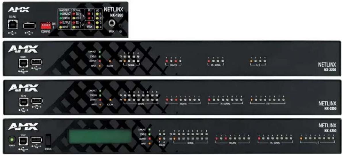
FIG. 1 displays the NX-series controllers.
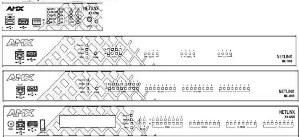
FIG. 1 NX-series controllers
The NX Series NetLinx Integrated Controllers use a combination lithium battery and clock crystal package. The battery is a commonly available CR2032 lithium battery. The battery has an average shelf life of 10 years. In normal use, the time will be shorter than the average shelf life depending on the amount of time the unit has no external power for the clock circuit. Typical useful life of the battery is 8 years under the specified temperature range. (see Operating Environment in the Specifications table for each type of NX controller in this chapter for more information.)
Related Documents
For information on using the on-board Web Console, as well as NetLinx send commands and terminal communications to configure the NX-series Controllers, refer to the NX Series NetLinx Integrated Controllers WebConsole & Programming Guide.
NOTE: All product documentation is available to view or download from www.amx.com.
What's New?
The following section lists the new features for the NX-series controllers. For more information about each of these items, see the What's New for NX-Series Controllers document located on the NX controllers product pages at www.amx.com.
Two Discrete Network Interfaces (NICs)
The NX-2200, NX-3200 and NX-4200 controllers have two 10/100BaseT Ethernet connections. The first, designated as LAN, is intended for connection to the Data Network for external network communications such as database access or scheduling. The second, the ICSLAN is intended for communication with AV devices.
Using the ICSLAN Network
The ICSLAN port has a built-in DHCP server. This DHCP server is enabled by default and will serve IP addresses to any connected devices set to DHCP mode.
For more information about using the ICSLAN network, DHCP servers, and opening LAN and ICSLAN sockets from code, see the ICSLAN Ports on page 33.
Automatic Binding of AMX Devices on ICSLAN
When an ICSLAN device is set to NDP connection mode (the factory default), it will automatically be bound to the master when connected to its ICSLAN port if it's IP address is valid for the ICSLAN subnet.
Support for IPv6 Networks
The NX-Series controllers fully support IPv6 network addressing. If the LAN port is connected to an IPv6 capable network it will self select an appropriate IPv6 address based on the discovered address parameters of the network to which it's attached.
The controllers simultaneously support IPv4 network addressing. This means any controller may have more than one valid IP address: one IPv4 and one or more IPv6 addresses.
Link-Local Fallback in DHCP Mode
When the X-Series controller's LAN IP addressing mode is set to DHCP, it will attempt to acquire an IPv4 address from a DHCP server for approximately one minute after boot. If the controller does not receive a valid DHCP address in that time (e.g. if a DHCP server is not found), it will fall back to an IPv4 address in the link-local range.
Wired 802.1X Support
The X-Series controllers support wired 802.1X, an IEEE Standard for Port-based Network Access Control.
ID Pushbutton Functionality
The X-Series controllers include new ID pushbutton functionality. For more information, see the ID Pushbutton on page 34.
Serial Ports Differences
Unlike current NI controllers, not all serial ports on the X-series controllers support RS-422 and RS-485. The NX-1200 and NX-2200 have one serial port that supports RS-232/422/485, and the NX-3200 and NX-4200 have two. The rest of the serial ports (1 on the NX-1200, 3 on the NX-2200 and 6 on the NX-3200 and NX-4200) support only the RS-232 protocol.
Serial, IR, and AxLink Port Diagnostics
When a string is sent to a serial port or an IR pulse to an IR port, the X-Series controllers can detect and report if the port being used is in a fault condition. The controllers can also detect certain fault conditions on the AxLink bus.
AxLink Power Measurement and Control
Important: The NX-Series controllers can NOT be powered via the AxLink port. The +12V pin on the AxLink connectors are designed only for voltage output. Do NOT connect +12V from a power supply or the NXA-PDU to the +12V pin on the AxLink connectors, or you may permanently damage the NX controller and/or the power supply.
The AxLink ports on X-Series controller support a new NetLinx command to turn on and off +12V power output on the port.
Case Sensitive File System
Unlike the NI-Series controllers, all file names on the X-Series controllers are case sensitive. This includes all user files created or used within NetLinx or Java code.
USB Program Port
The X-Series controllers utilize a true USB port for configuration and programming via a connected PC.
USB Firmware Upgrade
All X-Series controllers support firmware upgrades via a USB solid-state drive. Selecting the desired .kit file and initiating the upgrade are done from telnet.
USB Program Download
All X-Series controllers support loading NetLinx program files via a USB solid-state drive. Selecting the desired .tkn file and initiating the upload are done from telnet.
USB Logging
If a USB storage device is connected via an X-Series controller's USB port it can be used to store a log of system status messages.
Copy and Clone Configuration
On any X-Series controller, configuration information can be exported to and imported from a USB storage device. There are two different levels of configuration export: "COPY" and "CLONE". See the NX Series NetLinx Integrated Controllers WebConsole & Programming Guide for information on using the EXPORT CONFIG and EXPORT CLONE telnet commands.
Difference in DEFINE\_PROGRAM Program Execution
Due to differences in the underlying architecture of the X-Series masters, changing variables in the DEFINE_PROGRAM section of code can negatively impact program performance.
External SD Card Slot (NX-3200 and NX-4200 only)
The external SD card slot in the NX-3200 and NX-4200 is for future use. Until firmware is available that supports the use of an external SD card, it is recommended that the card slot be left empty.
Redundant Power Source (NX-4200 only)
The NX-4200 can be powered either with a connection to the main AC power (110/220VAC) or from an external 12V DC power supply.
Power Button (NX-4200 only)
The NX-4200 includes a momentary button on the front panel that can be used to turn on and off the unit.
Front Panel LCD Status Display (NX-4200 only)
The NX-4200 includes a 2-line by 20-character display on the front panel to display status information. The toggle switch next the display scrolls through a fixed list of information about the unit and its current configuration.
4-Port PoE ICSLAN Switch (NX-4200 only)
The NX-4200 includes four ICSLAN connection ports via a built-in 4-port switch. When powered by an AC source, the NX-4200 can supply power via PoE to each port on the 4-port switch.
Features
The following table summarizes the features for each NX-series controller:
| NX-Series Controllers - Features | |
| NX-1200 NetLinx Integrated Controllers | |
| Name / FG# Features | |
| NX-1200 Controller (FG2106-01) 1 RS-232 | / RS-422 / RS-485 serial port1 RS-232-only serial port2 IR / Serial ports4 Digital I/O ports1 AxLink port1 LAN Ethernet port1 IR Receiver port capable of interfacing with an AMX IR031 USB 2.0 host port1600 MIPS512 MB RAM4 GB Internal MicroSD Memory Card1 MB Non-volatile MemoryAMX Device Discovery enabled |
| NX-2200 NetLinx Integrated Controllers | |
| Name / FG# Features | |
| NX-2200 Controller (FG2106-02) 1 RS-232 | / RS-422 / RS-485 serial port3 RS-232-only serial ports4 Relays4 IR / Serial ports4 Digital I/O ports1 AxLink port1 ICSLAN Ethernet port1 LAN Ethernet port2 USB 2.0 host ports1600 MIPS512 MB RAM8 GB Internal MicroSD Memory Card1 MB Non-Volatile MemoryAMX Device Discovery enabled |
| NX-3200 NetLinx Integrated Controllers | |
| Name / FG# Features | |
| NX-3200 Controller (FG2106-03) 2 RS-232 | / RS-422 / RS-485 serial ports6 RS-232-only serial ports8 Relays8 IR/Serial ports8 Digital I/O ports2 AxLink ports1 ICSLAN Ethernet port1 LAN Ethernet port2 USB 2.0 host ports1600 MIPS512 MB RAM8 GB Internal MicroSD Memory Card1 MB Non-Volatile MemoryAMX Device Discovery enabled |
| NX-Series Controllers - Features (Cont.) | |
| NX-4200 NetLinx Integrated Controllers | |
| Name / FG# Features | |
| NX-4200 Controller (FG2106-04) 2 RS-232 | / RS-422 / RS-485 serial ports6 RS-232-only serial port8 Relays8 IR / Serial ports8 Digital I/O ports2 AxLink ports4 ICSLAN Ethernet ports1 LAN Ethernet port2 USB 2.0 host ports1600 MIPS1 GB RAM8 GB Internal MicroSD Memory Card1 MB Non-Volatile MemoryAMX Device Discovery enabled |
NX-1200
The NX-1200 (FG2106-01) has 512MB of on-board RAM, a 4GB CompactFlash card, and is Device Discovery enabled to simplify programming by standardizing device and function definitions, default touch panel button assignments, and control and feedback methods. A complete list of device specifications is listed below.
FIG. 2 displays the NX-1200.
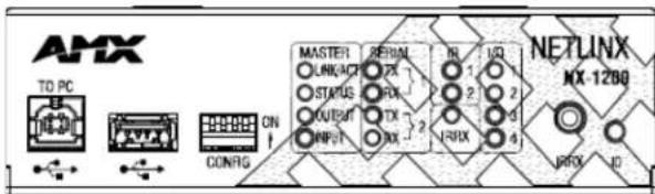
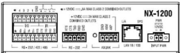
FIG. 2 NX-1200 (front and rear panels)
NOTE: Verify you are using the latest NX firmware for the on-board Master. Verify you are using the latest version of NetLinx Studio 4.0 (available for download from www.amx.com).
Port Numbers
The following table lists the port numbers on the NX-1200:
| NX-1200 Port Numbers | ||||
| RS-232 RS | -232/422/485 IR/ | Serial I/O IR/ | RX | |
| 2 | 1 | 1 | 1 | - |
1 2 2 2 2 0
NX-1200 Specifications
| NX-1200 Specifications | |
| Dimensions (HWD): 1.6 | 45" x 5.8" x 5.15" (41.78mm x 147.32mm x 130.81mm)RU: 1/3 |
| Active Power Requirements: | DC input voltage (typical): 12 VDCDC current draw: 200 mA @ 12 VDCDC range, voltage: 9-18 VDC |
| Active Power Consumption: | 3W |
| Mean Time Between Failures (MTBF): | 100,000 hours |
| Memory: • 512 MB DDRAM• 1 MB Non-volatile RAM (NVRAM)• 4 GB Internal MicroSD memory card | |
| Weight: 1.6 lbs (0.7257 kg) | |
| Enclosure: Metal with black matte finish | |
| Certifications: • FCC CF | R Title 47 Part 15CE EN 55022CE EN 55024CE EN 60950-1IEC 60950-1UL 60950-1C - T i c k C I S P R 2 2IC C I S P R 2 2V C C I C I S P R 2 2RoHS / WEEE compliant |
| Front Panel Components: | |
| Program Port: | 1 Type-B USB port that can connect to a USB port on a PC and access the NetLinx Studio program for controller configuration. |
| USB Port: | 1 Type-A USB port for connecting a mass storage device for loading .tkn files, reading or writing configuration files and log files, or updating the firmware on the unit. |
| Configuration DIP Switch: | The Configuration DIP Switch allows you to set boot-time operations (see the Configuration DIP Switch section on page 32 for more information.) |
| Master LEDs: | LINK/ACT (green): Blinks when the Ethernet cables are connected and terminated correctly. Also blinks when receiving Ethernet data packets.STATUS (green): Blinks to indicate that the system is programmed and communicating properly.OUTPUT (red): Blinks when the Controller transmits data, sets channels On and Off, sends data strings, etc.INPUT (yellow): Blinks when the Controller receives data from button pushes, strings, commands, channel levels, etc. |
| Serial LED(red / yellow): | 2 sets of LEDs light to indicate that RS-232 ports 1-2 are transmitting or receiving RS-232, 422, or 485 data(red = TX, yellow = RX). |
| IR LED (red): | 2 LEDs light to indicate the IR/Serial ports 11-12 are transmitting control data. LED indicator for each IR port remains lit for the length of time that IR/Serial data is being generated. |
| IRRX LED (red): | 1 LED light to indicate the IRRX channel is receiving control data via the IRRX port. The LED indicator remains lit for the length of time that IR data is being received. |
| Digital I/O LED(yellow): | Lights when I/O channels 1-4 are active. The LED for each I/O port reflects the state of that particular port. |
| IRRX Port: | 1 1/8" mini-phono connector for Interfacing with an IR03 IR receiver. |
| ID Pushbutton: | 1 black ID pushbutton used during boot to revert to factory configuration or factory firmware. Also used after boot to toggle IP mode between Static and DHCP. |
| Rear Panel Components: | |
| Digital I/O (Port 22): | 1 6-pin 4-channel binary I/O port for contact closure with each input being capable of voltage sensing. Input format is software selectable with interactive power sensing for IR ports. |
| IR/Serial(Ports 11-12): | 2 2-pin IR/Serial control ports support high-frequency carriers of up to 1.142 MHz with each output being capable of two electrical formats: IR or Serial.2 IR/Serial data signals can be generated simultaneously.IR ports support data mode (at limited baud rates and wiring distances). |
| RS-232/422/485(Port 1): | 1 10-pin RS-232/422/485 control ports using 3.5 mm mini-Phoenix (male) connectors with XON/XOFF (transmit on/transmit off), CTS/RTS (clear to send/ready to send). Supports 300-115,200 baud. |
| NX-1200 Specifications (Cont.) | |
| Rear Panel Components: (Cont.) | |
| RS-232 (Port 2): 1 5-pin RS-232 control port using 3.5 mm mini-Phoenix (male) connectors with XON/XOFF (transmit on/transmit off), CTS/RTS (clear to send/ready to send). Supports 300-115,200 baud. | |
| AxLink Port: | 1 4-pin 3.5 mm mlni-Phoenix (male) connector that provides data and power to external AxLink control devices. Green AxLink LED indicates the state of the AxLink port. |
| LAN 10/100 Port: | 1 RJ-45 connector provides Ethernet communication. This is an Auto MDI/MDI-X enabled port, which allows you to use either straight-through or crossover Ethernet cables.The LAN Port LEDs show communication activity, connection status, speeds, and mode information:SPD (speed) - Yellow LED lights On when the connection speed is 100 Mbps and turns Off when the speed is 10 Mbps.L/A (link/activity) - Green LED lights On when the Ethernet cables are connected and terminated correctly, and blinks when receiving Ethernet data packets. |
| Power Connection: 2-pin 3.5 mm mini-Phoenix (male) connector with retention screws provides power to the NX-1200. | |
| General Specifications: | |
| Operating Environment: | Operating Temperature: 32^ F ( 0^ C) to 122^ F ( 50^ C)Storage Temperature: 14^ F ( -10^ C) to 140^ F ( 60^ C)Operating Humidity: 5% to 85% RHHeat Dissipation (On): 10.2 BTU/hr |
| Included Accessories: | 1 2-pin 3.5 mm mini-Phoenix (female) PWR connector1 4-pin 3.5 mm minl-Phoenix (female) AxLink connector1 6-pin 3.5 mm mini-Phoenix (female) I/O connector1 10-pin 3.5mm mini-Phoenix (female) RS232/422/485 connector1 5-pin 3.5mm mlnl-Phoenix (female) RS232 connector1 CC-NIRC, IR Emitters (FG10-000-11) |
NX-2200
The NX-2200 (FG2106-02) has 512MB of on-board RAM, a 4GB CompactFlash card, and is Device Discovery enabled to simplify programming by standardizing device and function definitions, default touch panel button assignments, and control and feedback methods. A complete list of device specifications is listed below.
FIG. 3 displays the NX-2200.
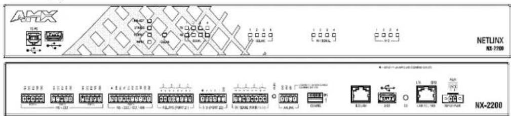
FIG. 3 NX-2200 (front and rear panels)
NOTE: Verify you are using the latest NX firmware for the on-board Master. Verify you are using the latest version of NetLinx Studio 4.0 (available for download from www.amx.com).
Port Numbers
The following table lists the port numbers for the NX-2200:
| NX-2200 Port Numbers | |||||
| RS-232 RS-232/422/485 IR/$ | Serial I/O Relay | ||||
| 2-4 1 11-14 22 21 | |||||
NX-2200 Specifications
| NX-2200 Specifications | |
| Dimensions (HWD): 1.766" x 17" x 9.12" (44.85mm x 431.8mm x 231.64mm)RU: 1 | |
| Active Power Requirements: | DC input voltage (typical): 12 V_DC DC current draw: 250 mA @ 12 V_DC DC range, voltage: 9-18 V_DC |
| Active Power Consumption: | 4.2W |
| Mean Time Between Failures (MTBF): | 100,000 hours |
| Memory: • 512 MB RAM | 1 MB Non-volatile RAM (NVRAM)8 GB Internal MicroSD memory card |
| Weight: 6.08 lbs (2.7578 kg) | |
| Enclosure: Metal with black matte finish | |
| Certifications: • FCC CFR Title 47 Part 15CE EN 55022CE EN 55024CE EN 60950-1IEC 60950 - 1UL 60950 - 1C - T i c k C I S P R 2 2IC C I S P R 2 2V C C I C I S P R 2 2RoHS / WEEE compliant | |
| Front Panel Components: | |
| Program Port: | 1 Type-B USB port that can connect to a USB port on a PC and access the NetLinx Studio program for controller configuration. |
| USB Port: | 1 Type-A USB port for connecting a mass storage device for loading .tkn files, reading or writing configuration files and log files, or updating the firmware on the unit. |
| Master LEDs: | LINK/ACT (green): Blinks when the Ethernet cables are connected and terminated correctly. Also blinks when receiving Ethernet data packets.STATUS (green): Blinks to indicate that the system is programmed and communicating properly.OUTPUT (red): Blinks when the Controller transmits data, sets channels On and Off, sends data strings, etc.INPUT (yellow): Blinks when the Controller receives data from button pushes, strings, commands, channel levels, etc. |
| ICSLAN LEDs (red): | 1 LED which blinks when the RJ-45 cables to port 1 is connected and terminated correctly. The LED also blinks when receiving LAN data packets. |
| Serial LEDs (red): | 2 sets of four LEDs, each of which light to indicate that the corresponding RS-232 ports (2-4) and RS-232/422/485 port (1) are transmitting or receiving RS-232, 422, or 485 data. |
| Relay (red): | 4 LEDs light to indicate the relay channels 1-4 are active (closed). These LEDs reflect the state of the relay on port 21. |
| IR/Serial (red): | 4 LEDs light to indicate the IR/Serial ports 11-14 are transmitting control data. LED indicator for each IR port remains lit for the length of time that IR/Serial data is being generated. |
| Digital I/O (yellow): | Lights when the I/O channels 1-4 are active. The LED for each I/O port reflects the state of that particular port. |
| Rear Panel Components: | |
| RS-232/422/485 (Port 1): | 1 10-pin RS-232/422/485 control ports using a 10-pin 3.5 mm mini-Phoenix (male) connector with XON/XOFF (transmit on/transmit off), CTS/RTS (clear to send/ready to send). Supports 300-115,200 baud. |
| RS-232 (Ports 2-4): | 3 5-pin RS-232 control ports using 5-pin 3.5 mm mini-Phoenix (male) connectors with XON/XOFF (transmit on/transmit off), CTS/RTS (clear to send/ready to send). Supports 300-115,200 baud. |
| Relay (Port 21): | 4 2-pin 4-channel single-pole single-throw relay ports.Each relay is independently controlled.Supports up to 4 independent external relay devicesChannel range = 1-4Each relay can switch up to 24 V_DC or 28 V_AC @ 1 A 8-pin 3.5 mm mini-Phoenix (male) connector provides connection to relays |
| Digital I/O (Port 22): | 4-channel binary I/O port for contact closure with each input being capable of voltage sensing. Input format is software selectable with Interactive power sensing for IR ports. |
| NX-2200 Specifications (Cont.) | |
| Rear Panel Components: (Cont.) | |
| IR/Serial(Ports 11-14): | 4 IR/Serial control ports support high-frequency carriers of up to 1.142 MHz with each output being capable of two electrical formats: IR or Serial.4 IR/Serial data signals can be generated simultaneously.IR ports support data mode (at limited baud rates and wiring distances). |
| AxLink Port: | 4-pin 3.5 mm mini-Phoenix (male) connector that provides data and power to external AxLink control devices.Green AxLink LED indicates the state of the AxLink port. |
| Configuration DIPSwitch: | The Configuration DIP Switch allows you to set boot-time operations (see Configuration DIP Switch section on page 32 for more information.) |
| ICSLAN: 1 RJ-45 connector for ICSLAN interface. | |
| USB Port: | 1 Type-A USB port for connecting a mass storage device for loading .tkn files, reading or writing configuration files and log files, or updating the firmware on the unit. |
| ID Pushbutton: | 1 black ID pushbutton used during boot to revert to factory configuration or factory firmware. Also used after boot to toggle IP mode between Static and DHCP. |
| LAN 10/100 Port: | 1 RJ-45 connector provides TCP/IP communication. This is an Auto MDI/MDI-X enabled port, which allows you to use either straight-through or crossover Ethernet cables.The Ethernet Port LEDs show communication activity, connection status, speeds, and mode information:SPD (speed) - Yellow LED lights On when the connection speed is 100 Mbps and turns Off when the speed is 10 Mbps.L/A (link/activity) - Green LED lights On when the Ethernet cables are connected and terminated correctly, and blinks when receiving Ethernet data packets. |
| Power Connection: | 2-pin 3.5 mm mini-Phoenix (male) connector with retention screws provides power to the NX-2200. |
| General Specifications: | |
| OperatingEnvironment: | Operating Temperature: 32^ F ( 0^ C) to 122^ F ( 50^ C)Storage Temperature: 14^ F ( -10^ C) to 140^ F ( 60^ C)Operating Humidity: 5% to 85% RHEat Dissipation (On): 14.3 BTU/hr |
| Included Accessories: | 1 2-pin 3.5 mm mini-Phoenix (female) PWR connector1 4-pin 3.5 mm mini-Phoenix (female) AxLink connector1 6-pin 3.5 mm mini-Phoenix (female) I/O connector1 10-pin 3.5mm mini-Phoenix (female) RS232/422/485 connector3 5-pin 3.5mm mini-Phoenix (female) RS232 connectors2 CC-NIRC, IR Emitters (FG10-000-11)removable rackears |
NX-3200
The NX-3200 (FG2106-03) has 512MB of on-board RAM, a 4GB CompactFlash card, and is Device Discovery enabled to simplify programming by standardizing device and function definitions, default touch panel button assignments, and control and feedback methods. A complete list of device specifications is listed below.
FIG. 4 displays the NX-3200.
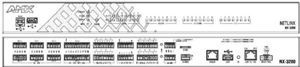
FIG. 4 NX-3200 (front and rear panels)
NOTE: Verify you are using the latest NX firmware for the on-board Master. Verify you are using the latest version of NetLinx Studio 4.0 (available for download from www.amx.com).
Port Numbers
The following table lists the port numbers for the NX-3200:
| NX-3200 Port Numbers | ||||
| RS-232 RS-232/422/485 IR/S | Serial I/O Relay | |||
| 2-4, 6-8 1 | 5 11-18 22 21 | |||
NX-3200 Specifications
| NX-3200 Specifications | |
| Dimensions (HWD): 1.766" x 17" x 9.12" (44.85mm x 431.8mm x 231.64mm)RU: 1 | |
| Active Power Requirements: | • DC Input voltage (typical): 12 VDC• DC current draw: 400 mA @ 12 VDC• DC range, voltage: 9-18 VDC |
| Active Power Consumption: | 6.6W |
| Mean Time Between Failures (MTBF): | 100,000 hours |
| Memory: • 512 MB RAM | • 1 MB Non-volatile RAM (NVRAM)• 8 GB Internal MicroSD memory card |
| Weight: 6.1 lbs (2.7669 kg) | |
| Enclosure: Metal with black matte finish | |
| Certifications: | • FCC CFR Title 47 Part 15• CE EN 55022• CE EN 55024• CE EN 60950-1• IEC 60950-1• UL 60950-1• C-Tick CISPR 22• IC CISPR 22• VCCI CISPR 22• RoHS / WEEE compliant |
| Front Panel Components: | |
| Program Port: | 1 Type-B USB port that can connect to a USB port on a PC and access the NetLinx Studio program for controller configuration. |
| USB Port: | 1 Type-A USB port for connecting a mass storage device for loading .tkn files, reading or writing configuration files and log files, or updating the firmware on the unit. |
| Master LEDs: | • LINK/ACT (green): Blinks when the Ethernet cables are connected and terminated correctly. Also blinks when receiving Ethernet data packets.• STATUS (green): Blinks to indicate that the system is programmed and communicating properly.• OUTPUT (red): Blinks when the Controller transmits data, sets channels On and Off, sends data strings, etc.• INPUT (yellow): Blinks when the Controller receives data from button pushes, strings, commands, channel levels, etc. |
| ICSLAN LEDs (red): | 1 LED which blinks when the RJ-45 cables to port 1 is connected and terminated correctly. The LED also blinks when receiving LAN data packets. |
| Serial LEDs (red): | 2 sets of eight LEDs, each of which light to indicate that the corresponding RS-232 ports (2-4, 6-8) and RS-232/422/485 ports (1, 5) are transmitting or receiving RS-232, 422, or 485 data. |
| Relay LEDs (red): | 1 set of 8 LEDs, each of which light to indicate the corresponding relay channels (1-8) are active (closed). These LEDs reflect the state of the relay on port 21. |
| IR/Serial LEDs (red): | 1 set of 8 LEDs, each of which light to indicate the IR/Serial channels 1-8 are transmitting control data on the corresponding IR/Serial ports (ports 11-18). The LED indicator for each IR port remains lit for the length of time that IR/Serial data is being generated. |
| Digital I/O LEDs (yellow): | 1 set of 8 LEDs, each of which light when the corresponding rear I/O channels (1-8) are active. The LED for each I/O port reflects the state of that particular port. |
| Rear Panel Components: | |
| RS-232 (Ports 2-4, 6-8): | 6 5-pin RS-232 control ports using 5-pin 3.5 mm mini-Phoenix (male) connectors with XON/XOFF (transmit on/transmit off), CTS/RTS (clear to send/ready to send). Supports 300-115,200 baud. |
| RS-232/422/485 (Ports 1 and 5): | 2 10-pin RS-232/422/485 control ports using a 10-pin 3.5 mm mini-Phoenix (male) connector with XON/XOFF (transmit on/transmit off), CTS/RTS (clear to send/ready to send). Supports 300-115,200 baud. |
| NX-3200 Specifications (Cont.) | |
| Rear Panel Components: (Cont.) | |
| Relays (Port 21): 8-channel single-pole single-throw relay portEach relay is independently controlled.Supports up to 8 independent external relay devicesChannel range = 1-8Each relay can switch up to 24 V_DC or 28 V_AC @ 1 ATwo 8-pin 3.5 mm mInl-Phoenix (male) connectors provide connection to relays | |
| Digital I/O (Port 22): | 8-channel binary I/O port for contact closure with each input being capable of voltage sensing. Input format is software selectable with interactive power sensing for IR ports. |
| IR/Serial(Ports 11-18): | 8 IR/Serial control ports support high-frequency carriers of up to 1.142 MHz with each output being capable of two electrical formats: IR or Serial.8 IR/Serial data signals can be generated simultaneously.IR ports support data mode (at limited baud rates and wiring distances). |
| SDHC Slot: 1 SDHC card slot for future use. | |
| Configuration DIP Switch: | The Configuration DIP Switch allows you to set boot-time operations (see the Configuration DIP Switch section on page 32 for more information.) |
| ICSLAN Ports: 1 RJ-45 connector for ICSLAN Interface | |
| USB Port: | 1 Type-A USB port for connecting a mass storage device for loading .tkn files, reading or writing configuration files and log files, or updating the firmware on the unit. |
| ID Pushbutton: | 1 black ID pushbutton used during boot to revert to factory configuration or factory firmware. Also used after boot to toggle IP mode between Static and DHCP. |
| LAN 10/100 Port: | RJ-45 connector provides TCP/IP communication. This is an Auto MDI/MDI-X enabled port, which allows you to use either straight-through or crossover Ethernet cables.The Ethernet Port LEDs show communication activity, connection status, speeds, and mode information:SPD (speed) - Yellow LED lights On when the connection speed is 100 Mbps and turns Off when the speed is 10 Mbps.L/A (link/activity) - Green LED lights On when the Ethernet cables are connected and terminated correctly, and blinks when receiving Ethernet data packets. |
| AxLink Port: | 2 4-pin 3.5 mm mini-Phoenix (male) connectors that provides data and power to external AxLink control devices.Green AxLink LED indicates the state of the AxLink port. |
| Power Connection: | 2-pin 3.5 mm mini-Phoenix (male) connector with retention screws provides power to the NX-3200. |
| General Specifications: | |
| Operating Environment: | Operating Temperature: 32° F (0°C) to 122° F (50°C)Storage Temperature: 14° F (-10°C) to 140° F (60°C)Operating Humidity: 5% to 85% RHHeat Dissipation (On): 22.5 BTU/hr |
| Included Accessories: | 1 2-pin 3.5 mm mini-Phoenix (female) PWR connector2 4-pin 3.5 mm mInl-Phoenix (female) AxLink connector2 6-pin 3.5 mm mini-Phoenix (female) I/O connectors2 8-pin 3.5 mm mini-Phoenix (female) Relay connectors2 10-pin 3.5mm mini-Phoenix (female) RS232/422/485 connectors6 5-pin 3.5mm mini-Phoenix (female) RS232 connectors2 CC-NIRC, IR Emitters (FG10-000-11)2 removable rack ears |
NX-4200
The NX-4200 (FG2106-04) has 1GB of on-board RAM, a 13GB CompactFlash card, and is Device Discovery enabled to simplify programming by standardizing device and function definitions, default touch panel button assignments, and control and feedback methods. A complete list of device specifications is listed below.
FIG. 5 displays the NX-4200.
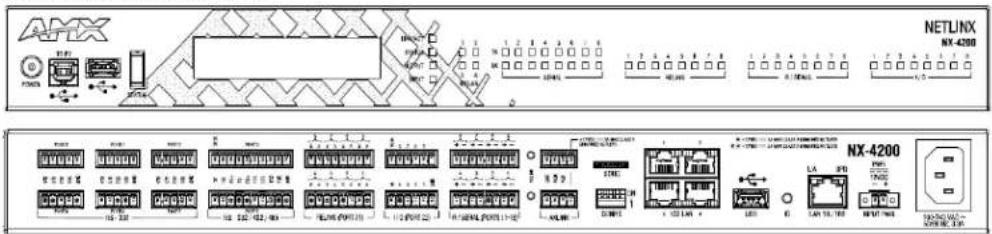
FIG. 5 NX-4200 (front and rear panels)
The NX-4200's on-board Master also provides the ability to update installed control card firmware.
NOTE: Verify you are using the latest NX firmware for the on-board Master. Verify you are using the latest version of NetLinx Studio 4.0 (available for download from www.amx.com).
Port Numbers
The following table lists the port numbers for the NX-4200:
| NX-4200 Port Numbers | |||||
| RS-232 RS-232/422/485 IR/$ serial I/O Re lay PoE | |||||
| 2-4, 6-8 1 | 5 11-18 22 21 24-27 | ||||
NX-4200 Specifications
| NX-4200 Specifications | |
| Dimensions (HWD): 1.766" | x 17" x 9.18" (44.85mm x 431.8mm x 233.17mm)RU: 1 |
| Active Power Requirements: | DC input voltage (typical): 12 V DCDC current draw: 200 mA @ 12 V DCDC range, voltage: 9-18 V DCAC voltage (typical): 100-240V AC 50/60Hz |
| Active Power Consumption: | 8.4W |
| Mean Time Between Failures (MTBF): | 100,000 hours |
| Memory: • 1 GB RAM | • 1 MB Non-volatile RAM (NVRAM)• 8 GB Internal MicroSD memory card |
| Weight: 7.6 lbs (3.4473 kg) | |
| Enclosure: Metal with black matte finish | |
| Certifications: • FCC CFR Title 47 Part 15• CE EN 55022• CE EN 55024• CE EN 60950-1• IEC 60950-1• U L 6 0 9 5 0 - 1• C - T i c k C I S P R 2 2• IC CISPR 22• V C C I C I S P R 2 2• RoHS / WEEE compliant | |
| Front Panel Components: | |
| Power: Press the Power button to power on or power off the controller. Hold for 2 seconds to power off. Momentary press to power back on. | |
| Program Port 1 Type-B USB port that can connect to a USB port on a PC and access the NetLinx Studio program for controller configuration. | |
| USB Port | 1 Type-A USB port for connecting a mass storage device for loading .tkn files, reading or writing configuration files and log files, or updating the firmware on the unit. |
| Display Control Button | 1 rocker-style tactile button for stepping through the supported status parameters displayed on the front panel LCD. |
| LCD Display | A 2 line by 20 character alphanumeric display for viewing status parameters. |
| Front Panel Components: (Cont.) | |
| Master LEDs: | LINK/ACT (green): Blinks when the Ethernet cables are connected and terminated correctly. Also blinks when receiving Ethernet data packets.STATUS (green): Blinks to indicate that the system is programmed and communicating properly.OUTPUT (red): Blinks when the Controller transmits data, sets channels On and Off, sends data strings, etc.INPUT (yellow): Blinks when the Controller receives data from button pushes, strings, commands, channel levels, etc. |
| ICSLAN LEDs | 4 LEDs which blinks when the RJ-45 cables to ports 1-4 are connected and terminated correctly. The LEDs also blink when receiving LAN data packets. |
| Serial LEDs (red): | 2 sets of eight LEDs, each of which light to indicate that the corresponding RS-232 ports (2-4, 6-8) and RS-232/422/485 ports (1, 5) are transmitting or receiving RS-232, 422, or 485 data. |
| Relay LEDs (red): | 1 set of 8 LEDs, each of which light to indicate the corresponding relay channels (1-8) are active (closed). These LEDs reflect the state of the relay on port 21. |
| IR/Serial LEDs (red): | 1 set of 8 LEDs, each of which light to indicate the IR/Serial channels 1-8 are transmitting control data on the corresponding IR/Serial ports (ports 11-18). The LED indicator for each IR port remains lit for the length of time that IR/Serial data is being generated. |
| Digital I/O LEDs (yellow): | 1 set of 8 LEDs, each of which light when the corresponding rear I/O channels (1-8) are active. The LED for each I/O port reflects the state of that particular port. |
| Rear Panel Components: | |
| RS-232 (Ports 2-4, 6-8) | 6 5-pin RS-232 control ports using 5-pin 3.5 mm mini-Phoenix (male) connectors with XON/XOFF (transmit on/transmit off), CTS/RTS (clear to send/ready to send). Supports 150-115,200 baud. |
| RS-232/422/485 (Ports 1, 5): | 2 10-pin RS-232/422/485 control ports using 10-pin 3.5 mm mini-Phoenix (male) connectors with XON/XOFF (transmit on/transmit off), CTS/RTS (clear to send/ready to send). Supports 150-115,200 baud. |
| NX-4200 Specifications (Cont.) | |
| Rear Panel Components: (Cont.) | |
| Relays (Port 21): 8-channel single-pole single throw relay portsEach relay is independently controlled.Supports up to 8 independent external relay devicesChannel range = 1-8Each relay can switch up to 24 V_ DC or 28 V_ AC@1 A Two 8-pin 3.5 mm mini-Phoenix (male) connectors provide connection to relays | |
| Digital I/O (Port 22): | 8-channel binary I/O port for contact closure with each input being capable of voltage sensing. Input format is software selectable with interactive power sensing for IR ports. |
| IR/Serial (Ports 11-18): | 8 IR/Serial control ports support high-frequency carriers of up to 1.142 MHz with each output being capable of two electrical formats: IR or Serial.8 IR/Serial data signals can be generated simultaneously.IR ports support data mode (at limited baud rates and wiring distances). |
| AxLink Port: | 2 4-pin 3.5 mm mini-Phoenix (male) connector that provides data and power to AxLink external control devices. Green AxLink LED indicates the state of the AxLink port. |
| SDHC Slot: 1 SDHC card slot for future use. | |
| Configuration DIP Switch: | The Configuration DIP Switch allows you to set boot-time operations (see theConfiguration DIP Switch on page 32 for more information.) |
| ICSLAN Ports: 4 RJ-45 connectors for ICSLAN interface with support for PoE. | |
| USB Port: | 1 Type-A USB port for connecting a mass storage device for loading .tkn files, reading or writing configuration files and log files, or updating the firmware on the unit. |
| ID Pushbutton: | 1 black ID pushbutton used during boot to revert to factory configuration or factory firmware. Also used after boot to toggle IP mode between Static and DHCP. |
| LAN 10/100 Port: 1 RJ-45 connector provides TCP/IP communication. This is an Auto MDI/MDI-X enabled port, which allows you to use either straight-through or crossover Ethernet cables.The Ethernet Port LEDs show communication activity, connection status, speeds, and mode information:SPD (speed) - Yellow LED lights On when the connection speed is 100 Mbps and turns Off when the speed is 10 Mbps.L/A (link/activity) - Green LED lights On when the Ethernet cables are connected and terminated correctly, and blinks when receiving Ethernet data packets. | |
| Power Connection: | 2-pin 3.5 mm mini-Phoenix (male) connector with retention screws provides power to the NX-4200. The NX-4200 can be powered either with a connection to the main AC power ( 110/220 V_ AC ) or from an external 12 V_ DC power supply. |
| General Specifications: | |
| Operating Environment: | Operating Temperature: 32^ F(0^ C) to 104^ F(40^ C) Storage Temperature: 14^ F(-10^ C) to 140^ F(60^ C) Operating Humidity: 5% to 85% RHHeat Dissipation (On): 28.7 BTU/hr |
| Included Accessories: | 1 2-pin 3.5 mm mini-Phoenix (female) PWR connector2 4-pin 3.5 mm mini-Phoenix (female) AxLink connector2 6-pin 3.5 mm mini-Phoenix (female) I/O connectors2 8-pin 3.5 mm mini-Phoenix (female) Relay connectors2 10-pin 3.5mm mini-Phoenix (female) RS232/422/485 connectors6 5-pin 3.5mm mini-Phoenix (female) RS232 connectors2 CC-NIRC, IR Emitters (FG10-000-11)2 removable rack ears |
Other AMX Equipment
This section lists optional AMX accessories and part numbers you may find useful for your NX controller. You can use all listed optional accessories with each model of NX controller.
• PSN6.5 - 6.5 A Power Supply (FG423-41)
• PSR4.5 - 4.5 A Power Supply (FG423-46)
• CC-USB-NI - USB Programming Cable (FG10-2105)
• CC-NIRC - IR Cables (FG10-000-11)
• CBL-ETH-FL, Ethernet Cat5e Flat Cable (FG1-2182-16)
- EXB-IRS4, ICSLan IR/S Interface, 4 IR/S and 4 Inputs (FG2100-23)
• EXB-COM2, ICSLan Serial Interface, 2 Ports (FG2100-22)
• EXB-REL8, ICSLan Relay Interface, 8 Channels (FG2100-20)
- EXB-I/08, ICSlan Input/Output Interface, 8 Channels (FG2100-21)
- EXB-MP1, ICSLan Multi-Port, 1 COM, 1 IR/S, 2 I/O, 1 IR RX (FG2100-26)
Serial, IR, AxLink, and PoE Port Diagnostics
When a string is sent to a serial port or an IR pulse to an IR port, the X-Series controllers can detect and report if the port being used is in a fault condition. The controllers can also detect certain fault conditions on the AxLink bus or Power-over-Ethernet (PoE) subsystem. The following fault conditions are recognized:
- The serial cable is not connected
- The Serial pin is connected to another pin
• The IR emitter is not connected
• The IR emitter is wired backwards - One or both AxLink bus data pins are shorted to power or ground
- The maximum power for all PoE ports (72W) has been exceeded or the power supply voltage is outside of the recommended limits
- The maximum current for a single PoE port has been exceeded or the load has disconnected from an individual port
On the first attempt to use a port that is in a fault condition, the controller will do the following:
- Quickly flash the front panel LED of the port being used 10 times
- Generate an ONERROR data event in NetLinx
- Report the error to any Duet Module that has claimed the port
- Report the error to RMS if the controller is connected to an RMS server
- Set an error flag for that port
The status of the error flag can be queried using the GET FAULT NetLinx command, which will result in a DATA EVENT where the return status can be parsed.
NOTE: If the fault condition persists, subsequent attempts to use the same port will only result in the quick flashing of the front panel LED. The ONERROR event and Duet Module or RMS reports only occur on the first attempt after booting the device or after the fault status is cleared. This prevents a flood of redundant error messages when a faulted port is used continuously.
The fault status is cleared on a successful transmission over the port, and also can be cleared manually using the CLEAR FAULT NetLinx command.
For serial and IR ports, an error condition is only checked at the time the port is used, so unused serial and IR ports will not generate errors. AxLink bus errors are checked at boot time.
Mounting the Controller
Use the rack-mounting brackets (supplied with the NX-2200/3200/4200) for equipment rack installations. Remove the mounting brackets and apply the rubber feet to the bottom of the controller for flat surface installations.
Installing the Controller into an Equipment Rack
The NX-2200/3200/4200 each ship with removable rack ears for installation into an equipment rack. The following instructions apply to the NX-2200/3200/4200.
Rack Mount Safety Instructions
Be sure to follow these important safety instructions when installing your central controller:
- If installed in a closed or multi-unit rack assembly, the operating ambient temperature of the rack environment may be greater than room ambient. Therefore, consideration should be given to installing the equipment in an environment compatible with the maximum ambient temperature 60^ C ( 140^ F).
- Installing the equipment in a rack should be such that the amount of air flow required for safe operation of the equipment is not compromised.
- Mounting the equipment in the rack should be such that a hazardous condition is not achieved due to uneven mechanical loading.
- Consideration should be given to the connection of the equipment to the supply circuit and the effect that overloading of the circuits might have on over current protection and supply wiring. Appropriate consideration of equipment nameplate ratings should be used when addressing this concern.
- Reliable earthing of rack-mounted equipment should be maintained. Particular attention should be given to supply connections other than direct connections to the branch circuit (e.g. use of power strips).
NOTE: To avoid repeating the installation, test the incoming wiring by connecting the Controller's connectors to their terminal locations and applying power. Verify that the unit is receiving power and functioning properly. Disconnect the terminal end of the power cable from the connected 12 VDC-compliant power supply.
- Use the supplied #8-32 screws to secure the rack ears to the sides of the controller. You can attach the rack ears toward the front or rear panel for either a front-facing or rear-facing installation.
- Slide the unit into the rack until the attachment holes, along both sides, align to their corresponding locations on the mounting brackets, as shown in FIG. 6.
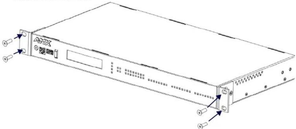
FIG. 6 Mounting Integrated Controller into an equipment rack
- Thread the cables through the opening in the equipment rack. Allow for enough slack in the cables to accommodate for movement during the installation process.
- Reconnect all cables to their appropriate source/terminal locations. Refer to the Wiring and Connections section on page 23 for more detailed wiring and connection information. Verify that the terminal end of the power cable is not connected to the power supply before plugging in the 2-pin power connector (or AC power connector on the NX-4200.)
- Secure the controller to the rack by using the four #10-32 screws supplied in the kit.
- Apply power to the unit to complete the installation.
Mounting the NX-1200
Mounting options for the NX-1200 are as follows:
- Rack mounting with an AVB-VSTYLE-RMK-1U, V Style Module Rack Mounting Tray (FG1010-720)
- Surface mounting with an AVB-VSTYLE-SURFACE-MNT, V Style Single Module Surface Mount (FG1010-722)
Consult the Mounting Options for V Style Modules Quick Start Guide included with the respective mounting kit for instructions on mounting the NX-1200. The NX-1200 also has rubber feet which you can apply to the bottom of the unit for table-top mounting.
Wiring and Connections
Overview
This chapter provides details, specifications, wiring diagrams, and other important information for all port and connectors available on the NX-series controllers.
FIG. 7 displays the NX-series controllers.
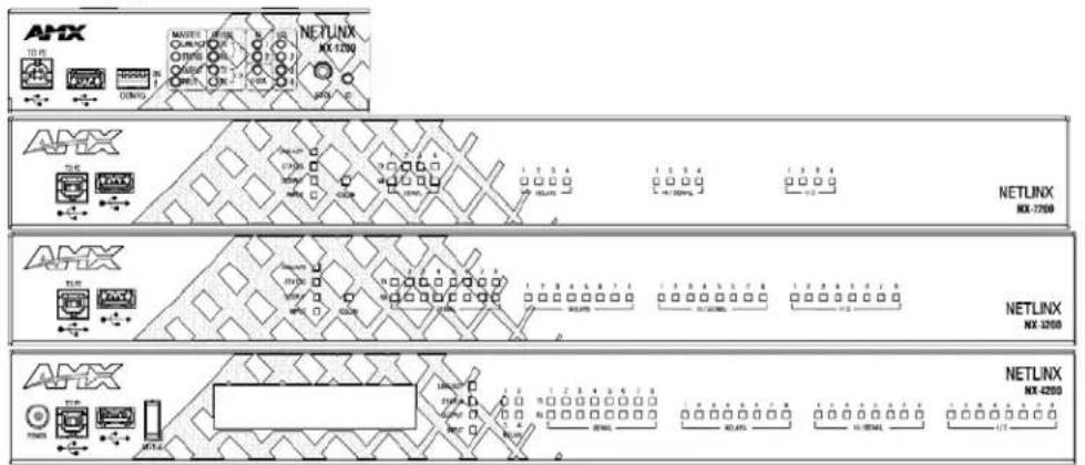
FIG. 7 NX-series controllers
Front Panel Components
The following sections list the front panel components on the NX-series controllers. Each component is featured on all NX-series controllers except where noted.
Power Button
The NX-4200 includes a momentary button on the front panel that you can use to turn on and turn off the unit. When you apply power to the unit, the power state is always on and the integrated LED is green. If you press the power button for more than two seconds while the unit is on, the unit turns off and the integrated LED changes to amber. Pressing the button momentarily while the unit is off turns it on and returns the integrated LED to green.
NOTE: The power button does not switch off AC power routed to the internal power supply. If AC power is used on the unit, AC power will still be present on the power supply AC input connections even when the unit is turned off.
If an internal power fault is detected, the LED integrated into the power button will flash yellow. This is an indication that the unit requires service.
FIG. 8 displays the Power button.

FIG. 8 Power button
Program Port
The front panel of all models features one Type-B USB port for connecting the controller to a PC via USB cable.
The Program port uses a standard Type-A-to-Type-B USB cable to connect to a PC. When connected, you can view your controller among the listed Masters connected via USB in NetLinx Studio. See the Initial Configuration chapter in the NX-Series Controllers WebConsole and Programming Guide for more information.
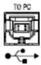
FIG. 9 Program port
USB Port
The front panel of all models features one Type-A USB port you can use to connect a mass storage device for loading .tkn files, reading or writing configuration files and log files, or updating the firmware on the unit.
NOTE: This USB port only supports a FAT32 file system.
This USB port (FIG. 10) uses standard USB cabling to connect to any mass storage or peripheral devices.

FIG. 10 USB port
NOTE: USB hubs are not supported on this port.
Status Button
The front panel of the NX-4200 features a rocker-style tactile button for stepping through the available status parameters displayed on the front panel LCD. You can press the button in the up or down directions to cycle through items on the LCD. This button is only available on the NX-4200.
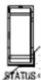
FIG. 11 Status button
Front Panel Display
The NX-4200 has a front panel display which you can use to view specific information and settings about the controller. You can use the Status button beside the display to cycle through the items on the display. All items on the display are view-only. The following table lists the items you can view on the front panel display:
| Front Panel Display Items | |
| Item Name Description | |
| Hostname The host name of the Master. | |
| System Number The system number of the Master. | Master. |
| Serial Number The serial number of the Master. | |
| LAN MAC Address The MAC address assigned to the Master via the LAN. | |
| LAN IPv4 Address The IP address assigned to the Master via the LAN. | |
| LAN IPv4 Address Type The IP address type. This reads either Static or Dynamic. | |
| LAN IPv4 Subnet Mask The subnet mask assigned to the Master via the LAN. | |
| LAN IPv6 Link Local Address | The IPv6 address assigned to the Master via the LAN. This address is not to be used for normal IP communication, including Master-to-Master. |
| LAN Default Gateway IPv4 Address The gateway address assigned to the Master via the LAN. | |
| LAN Default Gateway IPv6 Address | The gateway IPv6 address assigned to the Master via the LAN. |
| LAN DNS Server IPv4 Address | The DNS address assigned to the Master via the LAN. |
| LAN DNS Server IPv6 Address | The IPv6 DNS address assigned to the Master via the LAN. |
| ICSLAN MAC Address | The MAC address assigned to the Master via the ICSLAN. |
| ICSLAN IPv4 Address | The IP address assigned to the Master via the ICSLAN. |
| ICSLAN IPv4 Subnet Mask | The subnet mask assigned to the Master via the ICSLAN. |
| ICSLAN IPv6 Link Local Address | The IPv6 address assigned to the Master via the ICSLAN. |
| Master Firmware Version | The firmware version the Master is using. |
| Integrated Controller Firmware Version | The firmware version the Integrated controller is using. |
| PoE General Status | General PoE status codes. See the PoE General Status Format section on page 24 for a list of status definitions. |
| PoE Port Status | PoE port status codes. See the PoE Port Status section on page 25 for a list of condition codes. |
PoE General Status Format
The PoE General Status front panel display item contains the following status definitions:
- PoE Not Available - The system is not being powered from an AC source.
- OK: xx.xW - No general faults are present, where xx.x is the total power in watts currently being provided on the PoE ports.
- Max Power Exceeded - The total power drawn on the ports is greater than the PoE power capacity.
• Voltage Fault - The PoE voltage is out of range.
PoE Port Status
If the system is not being powered from an AC source, the status will read "PoE Not Available". Otherwise, the status consists of four subfields separated by blanks, each of the format x:cc, where x is the port number (1, 2, 3, or 4) and cc is the condition code. If there is not a fault on the port, the possible condition codes are as follows:
- N - No device is attached on the port or the device is not a PoE Powered Device.
- L - A PoE Powered Device of Class 1 or 2 is attached on the port.
- M - A PoE Powered Device of Class 0 or 3 is attached on the port.
- H - A PoE Powered Device of Class 4 is attached on the port.
• D - The port has been disabled.
- ED - A PoE Powered Device is attached on the port, but the load has been disconnected due to not drawing at least minimum current.
- EO - A PoE Powered Device is attached on the port, but has been shut off due to drawing more than maximum current or due to overheating on the controller's port.
Example:
PoE Port Status
1:N 2:M 3:ED 4:D
LEDs
This section details the various LEDs on the front panel of the NX-series controllers.
General Status LEDs
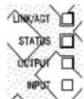
The General Status LEDs include the Link/Activity, Status, Output, and Input LEDs. These LEDs appear on all models of NX-series controllers.
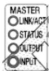
FIG. 12 displays the General Status LEDs for each NX-series controller.
NX-2200/3200/4200
NX-1200
FIG. 12 General Status LEDs
- Link/Act - Lights green when the link is up and toggles off when a data packet is sent or received.
- Status - Lights green and blinks once per second if the master is functioning normally and has established communication with a DHCP server.
- Input - Lights yellow when the controller receives data
- Output - Lights red when the controller transmits data
The following table lists the following special LED patterns for the Status, Input, and Output LEDs:
LED Patterns
| Mode Description | Status Output Input | |||
| OS Start Starting the Operating System ON ON ON | ||||
| Boot On-board Master is booting ON ON | ON | |||
| Contacting DHCP server | On-board Master is contacting a DHCP server for IP configuration information | ON OFF | Fast Blink | |
| Using link-local address | On-board Master could not find a DHCP server and is using a link-local address | Slow Blink | OFF | OFF |
| Downloading Boot firmware | Downloading Boot firmware to the Master's on-board Flash memory | Fast Blink* | Fast Blink* | Fast Blink* |
| Program running | Normal operation with a running program | Slow Blink | Normal | Normal |
| No program running | There is no NetLinx program loaded or the program is disabled | ON Normal | Normal | |
* - The fast blink is nearly instantaneous upon downloading the boot firmware to Flash memory and is, in most cases, undetectable to the user's eye.
ICSLAN LEDs
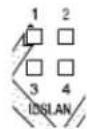
The ICSLAN LEDs light green when there is an active link on the corresponding ICSLAN port. The light toggles off when a data packet is sent or received.
There are 4 ICSLAN LEDs on the NX-4200. The NX-2200 and NX-3200 each have one ICSLAN LED (see FIG. 13).
NX-3200/4200

NX-2200
FIG. 13 ICSLAN LEDs
SERIAL LEDs
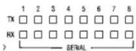
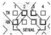
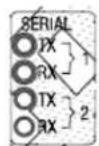
The SERIAL LEDs are two sets of LEDs which light to indicate that the RS-232 ports are transmitting or receiving RS-232, 422, or 485 data (red = TX, yellow = RX). The light toggles on when a data packet is sent or received.
There are two sets of eight SERIAL LEDs on the NX-3200 and NX-4200. The NX-2200 has two sets of four LEDs. The NX-1200 has two sets of two LEDs (see FIG. 14).
NX-3200/4200
NX-2200
NX-1200
FIG. 14 SERIAL LEDs
RELAYS LEDs
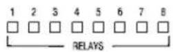
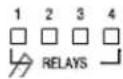
The RELAYS LEDs light red to indicate that the corresponding relay port is active. The light toggles off when the relay port is not engaged.
There are eight RELAY LEDs on the NX-3200 and NX-4200. The NX-2200 has four RELAY LEDs (see FIG. 15).
NX-2200NX-3200/4200
FIG. 15 RELAYS LEDs
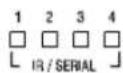
IR/SERIAL LEDs
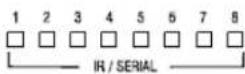
The IR/SERIAL LEDs light red to indicate that the corresponding IR/Serial port is transmitting data.
There are eight IR/SERIAL LEDs on the NX-3200 and NX-4200. The NX-2200 has four IR/SERIAL LEDs. The NX-1200 has two IR LEDs (see FIG. 16).
NX-3200/4200
NX-2200

NX-1200
FIG. 16 IR/SERIAL LEDs
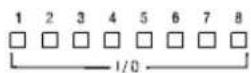
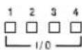
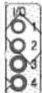
I/O LEDs
The I/O LEDs light yellow to indicate that the corresponding I/O port is active.
There are eight I/O LEDs on the NX-3200 and NX-4200. The NX-1200 and NX-2200 has four I/O LEDs (see FIG. 17).
NX-3200/4200
NX-2200
NX-1200
FIG. 17 I/O LEDs
IRRX LED
The IRRX LED lights red to indicate that the corresponding IRRX port is receiving data.
This LED is only available on the NX-1200 (see FIG. 18).

FIG. 18 IRRX LED
IRRX Port
The IRRX port is a 1/8" mini-phono receiver port capable of interfacing with an IR03 External IR Receiver Module. This port is only available on the NX-1200.
FIG. 19 displays the IRRX port.
FIG. 19 IRRX port
Rear Panel Components
The following sections list the rear panel components on the NX-series controllers.
FIG. 20 displays the rear panels of the NX-series controllers.

FIG. 20 NX-series controllers (rear panels)
Serial Ports
The NX-series controllers each feature device control serial ports that support either RS-232 or RS-232, RS-422, and RS-485 communication protocols. Each port supports the following specifications:
• XON/XOFF (transmit on/transmit off)
• CTS/RTS (clear to send/ready to send)
• 300-115,200 baud rate
RS-232 Ports
The RS-232 ports (ports 2-4 and 6-8 on the NX-3200/4200; ports 2-4 on the NX-2200; port 2 on the NX-1200) are 5-pin 3.5 mm mini-Phoenix (male) connectors used for connecting A/V sources and displays. These ports support most standard RS-232 communication protocols for data transmission.
FIG. 21 displays the RS-232 ports for the NX-series controllers.
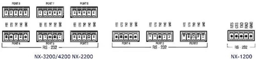
FIG. 21 RS-232 ports
The following table lists the pinouts for the RS-232 ports.
| RS-232 Port Pinouts | |
| Pin 1 GND | |
| Pin 2 RXD | |
| Pin 3 TXD | |
| Pin 4 CTS | |
| Pin 5 RTS | |
In the above table, pin 1 is located on the right side of the port, and the pinouts count up to the left.
RS-232/422/485 Ports
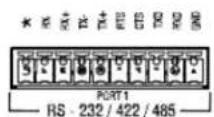
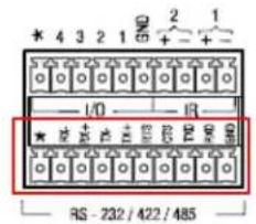
The RS-232/422/485 ports (ports 1 and 5 on the NX-3200/4200; port 1 on the NX-1200/2200) are 10-pin 3.5 mm mini-Phoenix (male) connectors used for connecting A/V sources and displays. By default, these ports are RS-422- and RS-485-disabled ports. These ports can be used as RS-232 ports by disabling RS-422 and RS-485 on the ports. Only with RS-422/485 disabled will the ports operate as RS-232. See the SET BAUD command and the TSET BAUD command in the NetLinx Programming chapter of the NX-Series Controllers WebConsole and Programming Guide for more information on disabling RS-422 and RS-485 on these ports. These ports support most standard RS-232, RS-422, and RS-485 communication protocols for data transmission.
FIG. 22 displays the RS-232/422/485 ports for each NX-series controller.

NX-3200/4200
NX-2200
NX-1200
FIG. 22 RS-232/422/485 ports
The following table lists the pinouts for the RS-232/422/485 ports.
| RS-232/422/485 Port Pinouts | |
| Pin 1 GND (used in RS-232 and RS-422) | |
| Pin 2 RXD (used in RS-232) | |
| Pin 3 TXD (used in RS-232) | |
| Pin 4 CTS (used in RS-232) | |
| Pin 5 RTS (used in RS-232) | |
| Pin 6 TX+ (used in RS-422 and RS-485) | |
| Pin 7 TX- (used in RS-422 and RS-485) | |
| Pin 8 RX+ (used in RS-422 and RS-485) | |
| Pin 9 RX- (used in RS-422 and RS-485) | |
| Pin 10 +12V | |
In the above table, pin 1 is located on the right side of the port, and the pinouts count up to the left.
Relay Ports
The relay ports (port 21 on the NX-2200/3200/4200) are 8-pin 3.5 mm mini-Phoenix (male) connectors used for connecting external relay devices. The NX-3200 and NX-4200 each features 2 sets of 8-pin relay connectors. The NX-2200 features one set of connectors. You can connect up to 8 independent external relay devices on both the NX-3200 and NX-4200 units, and 4 on the NX-2200. When a relay is "OFF", terminals A and B are open-circuit. When a relay is "ON", terminals A and B are shorted together.
Relay Connections
Use connectors A for common and B for output (FIG. 23). Each relay is isolated and normally open.
A metal connector strip is also provided to common multiple relays.
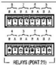
FIG. 23 RELAY connector (male)
• 8-channel single-pole single-throw relay ports
• Each relay is independently controlled
• Supports up to 8 independent external relay devices (4 on the NX-2200)
• Channel range = 1-8
• Each relay can switch up to 24 VDC or 28 VAC peak @ 1 A
- Two 8-pin 3.5mm mini-Phoenix (male) connector provides relay termination (One connector on the NX-2200)
I/O Ports
The I/O ports (port 22 on all NX-series controllers) are 6-pin 3.5 mm mini-Phoenix (male) connectors used for connecting logic-level outputs. The NX-3200 and NX-4200 each features 2 sets of 6-pin I/O connectors. The I/O port responds to either switch closures, voltage level (high/low) changes, or it can be used for logic-level outputs. Each port is capable of being used as an input or an output.
The I/O port detects a low signal (0 - 1.5 VDC) as a PUSH, and a high signal (>1.7 VDC) as a RELEASE. Voltages between 1.5V and 1.7V may be detected as a PUSH or a RELEASE.
FIG. 24 displays the I/O ports for each NX-series controller.
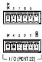
NX-3200/4200
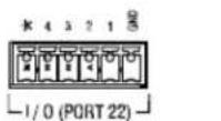
NX-2200 NX-1200
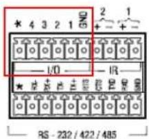
FIG. 24 I/O ports
- A contact closure between the GND and an I/O port is detected as a PUSH.
- When used for outputs, the I/O port acts as a switch to GND and is rated for 200mA @ 12 VDC.
• The NX-1200 and NX-2200 can use up to 4 I/O ports
• The NX-3200 and NX-4200 can use up to 8 I/O ports - The PWR pin provides +12 VDC @ 200 mA and is designed as a power output for the PCS Power Current Sensors, VSS2 Video Sync Sensors (or equivalent).
- The GND connector is a common ground and is shared by all I/O ports. A common ground is shared with I/O ports 1-8 (NX-3200/NX-4200) or with I/O ports 1-4 (NX-1200/NX-2200).
• The input impedance on the I/O port is 22k.
The following table list the wiring specifications for the I/O ports. In this table, pin 1 is located on the right side of the port, and the pinouts count up to the left.
| I/O Port Wiring Specifications | ||||||
| NX-3200/4200 NX-1200/2200 | Function | |||||
| Pin S | Signal Funct | on Pin Signal F | ||||
| 1 GND | Signal GND | 1 GND Signal | GNDInput/O | Output | ||
| 2 I/O | 1 Input/O | Output 2 I/O 1 I | ||||
| 3 I/O | 2 Input/O | Output 3 I/O 2 I | Input/O | Output | ||
| 4 | I/O 3 Input | Output 4 | I/O 3Input/O | Input | Output | |
| 5 I/O | 4 Input/O | Output 5 I/O 4 I | ||||
| 6 | 12 VDC | PWR | 6 | 12 VDC | PWR | |
| 7 | GND | Signal GND | ||||
| 8 | I/O 5 | Input/Output | ||||
| 9 | I/O 6 | Input/Output | ||||
| 10 | I/O 7 Input | Output | ||||
| 11 | I/O 8 Input | Output | ||||
| 12 | 12 VDC | PWR | ||||
IR/SERIAL Port: Connections and Wiring
The IR/SERIAL ports provide IR transmit/one-way serial connections that support high-frequency carriers up to 1.142 MHz. You can simultaneously generate up to eight IR/Serial data signals on the NX-4200 and NX-3200, up to four on the NX-2200, and up to two on the NX-1200.
These ports accept an IR Emitter (CC-NIRC) that mounts onto the device's IR window, or a mini-plug (CC-NSER) that connects to the device's control jack. You can also connect a data 0 - 5 VDC device to these ports.
NX-3200 and 4200 units each ship with two CC-NIRC IR Emitters (FG10-000-11). NX-1200 and 2200 units ship with one emitter each.
FIG. 25 displays the IR/SERIAL ports for each NX-series controller.
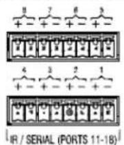
NX-3200/4200
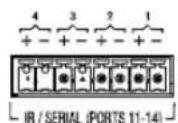
NX-2200
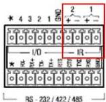
NX-1200
NOTE: The maximum baud rate for ports using DATA mode is 19200. Also, DATA mode works best when using a short cable length (< 10 feet).
FIG. 25 IR/SERIAL connector (male)
NOTE: For each data signal, the negative (-) terminal is for Signal GND, and the positive (+) terminal is for IR/Serial data.
The IR/Serial connector wiring specifications are listed in the following table.
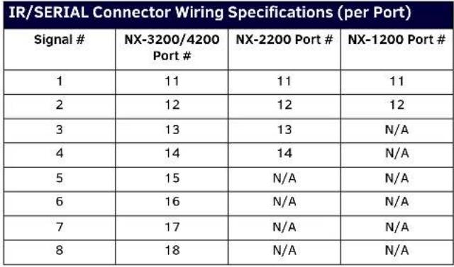 |
AxLink Port and LED (4-pin captive-wire)
The AxLink port allows the central controller to support AMX AxLink devices.
FIG. 26 displays the AXLINK ports for each NX-series controller.
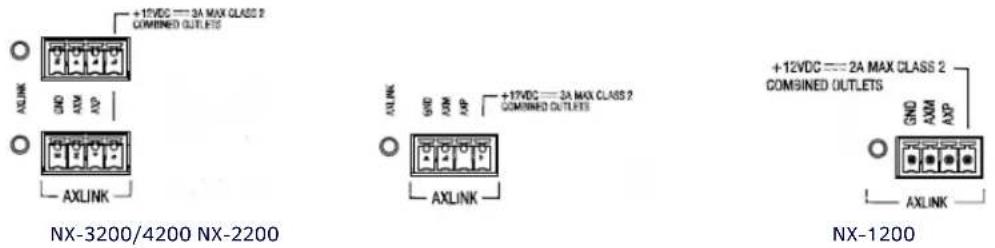
FIG. 26 AxLink Ports and LEDs
The (green) AxLink LED indicates AxLink data activity:
- Off - No power, or the controller is not functioning properly.
• 1 blink per second - Normal operation.
- 3 blinks per second - AxLink bus error. Check all AxLink bus connections.
The AxLink port can be used to supply power to downstream AxLink-compatible devices as long as the maximum current draw is less than 1.5 Amps on the NX-1200 and NX-2200, and 3 Amps on the NX-3200 and NX-4200. To isolate the central controller from high in-rush current, AxLink devices, or potential power faults on the AxLink bus, it is strongly recommended that you power external AxLink devices from an independent power supply.
NOTE: The AxLink port provides only limited power to connected AxLink devices. It is recommended to use an alternate power source when connecting AxLink devices to the central controller.
IMPORTANT: The NX-Series controllers CANNOT be powered via the AxLink port. The +12V pin on the AxLink connectors are designed only for voltage output. Do NOT connect +12V from a power supply or the NXA-PDU to the +12V pin on the AxLink connectors, or you may permanently damage the NX controller and/or the power supply.
The NX-3200 and NX-4200 each have two AxLink connections. These are two connection points for the same AxLink bus. All AxLink devices connected to the controller must have unique AxLink device numbers even if they are attached to different AxLink connection points on the controller.
While it is one AxLink bus, the power on these two AxLink connections is controlled independently.
Refer to the following table for the wiring length information used with the central controller:
| Wiring Guidelines | |
| Wire size Maximum wiring length | |
| 18 AWG 154.83 feet (47.19 meters) | |
| 20 AWG 98.30 feet (29.96 meters) | |
| 22 AWG 63.40 feet (19.32 meters) | |
| 24 AWG 38.68 feet (11.79 meters) |
FIG. 27 provides wiring requirements for the AxLink connector:
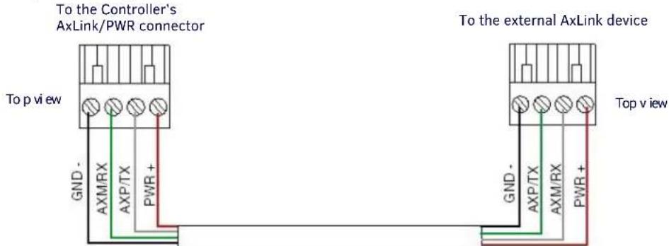
FIG. 27 Mini-Phoenix connector wiring diagram (direct data and power)
To use the 4-pin 3.5 mm mini-Phoenix (male) captive-wire connector for data communication and power transfer, the incoming PWR and GND cable from the 12 VDC-compliant power supply must be connected to the AxLink cable connector going to the central controller. FIG. 28 shows the wiring diagram:
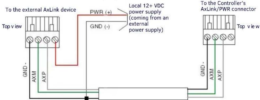
FIG. 28 4-pin mini-Phoenix connector wiring diagram (using external power source)
CAUTION: When you connect an external power supply, do not connect the wire from the PWR terminal (coming from the external device) to the PWR terminal on the Phoenix connector attached to the Controller unit. Make sure to connect only the AXM, AXP, and GND wires to the Controller's Phoenix connector when using an external power supply.
Make sure to connect only the GND wire on the AxLink/PWR connector when using a separate 12 VDC power supply. Do not connect the PWR wire to the AxLink connector's PWR (+) opening.
SDHC Card Slot
The NX-3200 and NX-4200 each feature an externally accessible SDHC card slot.
NOTE: The card slot is reserved for future use. Do not install a card in the card slot at this time.
FIG. 29 displays the SDHC card slot.

FIG. 29 SDHC Card Slot
Configuration DIP Switch
The NX-series controllers each have a configuration DIP switch which allows for certain operations to occur during boot-time. The DIP switch positions are assigned as follows:
- Switch for Program Run Disable
- Switch for Boot from External SD Card (only applicable to the NX-3200 and NX-4200.)
NOTE: The Configuration DIP Switch is located on the front panel of the NX-1200 and not the rear panel.
FIG. 30 displays the Configuration DIP Switch for the NX-series controllers.
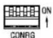
FIG. 30 Configuration DIP Switch
Program Run Disable (PRD) Mode
You can use the Configuration DIP switch to set the on-board Master to Program Run Disable (PRD) mode. PRD mode prevents the NetLinx program stored in the on-board Master from running when you power up the Integrated Controller. You should only use PRD mode when you suspect the resident NetLinx program is causing inadvertent communication and/or control problems.
If necessary, place the on-board Master in PRD mode and use the NetLinx Studio program to resolve the communication and/or control problems with the resident NetLinx program. Then download the new NetLinx program and try again.
FIG. 31 displays the default DIP switch settings and the settings for PRD mode. To switch to PRD mode, move the position 1 DIP switch to ON.
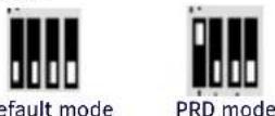
FIG. 31 DIP Switch settings - PRD mode
NOTE: Consider equating PRD Mode to a PC's SAFE Mode setting. With PRD mode, you can continue to power a unit, update the firmware, and download a new program while circumventing any problems with a currently downloaded program. You must power cycle the unit after activating/deactivating PRD mode on Program Port DIP switch #1.
ICSLAN Ports
The NX-2200/3200/4200 controllers have two types of Ethernet ports: LAN and ICSLAN. The LAN port is used to connect the master to an external network, and the ICSLAN ports are used to connect to other AMX equipment or third-party A/V equipment. The ICSLAN ports on all models provide Ethernet Communication to connected AMX Ethernet Equipment in a way that is isolated from the primary LAN connection.
The ICSLAN port is a 10/100 Port RJ-45 connector and Auto MDI/MDI-X enabled. The NX-4200 features four ICSLAN ports, while the NX-2200/3200 feature one each. The ports on the NX-4200 feature Power-over-Ethernet (PoE). The ports support IPv4 and IPv6 networks, as well as HTTP, HTTPS, Telnet, and FTP.
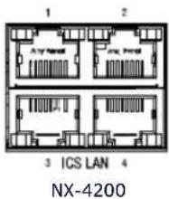
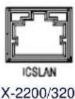
FIG. 32 ICSLAN ports
When powered by an AC source, the NX-4200 can supply power via PoE to each port on the 4-port switch. The NX-4200 supports hi-powered PoE (802.3at STANDARD), but the total power draw of all four ports cannot exceed 72W.
The ICSLAN port gets its IP addresses in one or more of the following ways:
- IPv4 - Static assignment of the subnetwork address by the user
• IPv6 - Link local address
Using the ICSLAN Network
The default IP address for the ICSLAN network is 198.18.0.1 with a subnet mask of 255.255.0.0.
It is important that the ICSLAN and LAN subnets do not overlap. If the LAN port is configured such that its address space overlaps with the ICSLAN network, the ICSLAN network will be DISABLED.
DHCP Server
The ICSLAN port has a built-in DHCP server. This DHCP server is enabled by default and will serve IP addresses to any connected devices set to DHCP mode.
The DHCP server can be disabled from telnet with the command:
SET ICSLAN
The DHCP address range is fixed. The server will provide addresses in the range x.x.0.2 through x.x.63.255.
Devices using static IP addresses on the ICSLAN network should be set within the reserved static IP address range of x.x.64.1 to x.x.255.254.
Opening LAN and ICSLAN Sockets from Code
When opening sockets from NetLinx or Java code there is no mechanism to indicate which network to use. The controller will open the socket on whichever network has an IP subnet that matches the address provided in the command to open the socket. There is no indication which network was used, only whether the socket was created successfully.
USB Port
The front panel of all NX-series controllers features one Type-A USB port you can use to connect a mass storage device for loading .jar files and IR data files (.irl), reading or writing configuration files and log files, or updating the firmware on the unit. The rear panels of the NX-2200/3200/4200 also feature an additional USB port.
NOTE: This USB port only supports a FAT32 file system.
This USB port (FIG. 33) uses standard USB cabling to connect to any mass storage or peripheral devices.
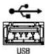
FIG. 33 USB port
NOTE: USB hubs are not supported on this port.
ID Pushbutton
All NX-series controllers feature an ID pushbutton which you can use to toggle between static and dynamic IP addressing. You can also use the pushbutton to reset the default settings on the controller or restore the controller to its factory firmware image.
FIG. 34 displays the ID pushbutton for the NX-series controllers.

ID
FIG. 34 ID pushbutton
NOTE: The ID pushbutton is located on the front panel of the NX-1200 and not on the rear panel.
Switching to Static or Dynamic IP Addressing.
To toggle between static or dynamic IP addressing, the controller cannot be currently booting or it must be in ID Mode. If these conditions are met, holding the ID pushbutton for 10 seconds changes the current IP addressing mode.
Restoring the Controller Settings to the Factory Defaults
To restore the controller settings to the factory defaults, the controller must be currently booting and you must press the ID pushbutton for 10 seconds. The controller is booting when the Status, Input, and Output LEDs turn on briefly then turn off. Shortly after, the Status and Input LEDs blink periodically. Resetting to factory defaults includes resetting the static IP address to its default and deleting the NetLinx program.
CAUTION: Pressing the ID pushbutton for 20 seconds restores the factory firmware image on the controller. Do not press the pushbutton significantly longer than the necessary 10 seconds if you only want to restore the default settings on the controller.
Restoring the Controller's Factory Firmware Image
To restore the controller's factory firmware image, the controller must currently be booting and you must press the ID pushbutton for 20 seconds. This also deletes all code and IRL files.
LAN 10/100 Port
All NX-series controllers feature a LAN 10/100 port to provide 10/100 Mbps communication via Category cable. This is an Auto MDI/MDI-X enabled port, which allows you to use either straight-through or crossover Ethernet cables. The port support IPv4 and IPv6 networks, as well as HTTP, HTTPS, Telnet, and FTP.
The LAN port automatically negotiates the connection speed (10 Mbps or 100 Mbps), and whether to use half duplex or full duplex mode.
FIG. 35 displays the LAN port for the NX-series controllers.
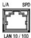
FIG. 35 LAN 10/100 port
FIG. 36 provides the pinouts and signals for the LAN connector and cable.
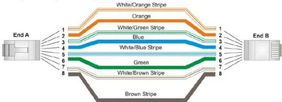
flowchart
graph LR
    A["End A"] --> B["White/Orange Stripe"]
    A --> C["Orange"]
    A --> D["White/Green Stripe"]
    A --> E["Blue"]
    A --> F["White/Blue Stripe"]
    A --> G["Green"]
    A --> H["White/Brown Stripe"]
    A --> I["Brown Stripe"]
    B --> J["1"]
    B --> K["2"]
    B --> L["3"]
    B --> M["4"]
    B --> N["5"]
    B --> O["6"]
    B --> P["7"]
    B --> Q["8"]
    C --> R["1"]
    C --> S["2"]
    C --> T["3"]
    C --> U["4"]
    C --> V["5"]
    C --> W["6"]
    C --> X["7"]
    C --> Y["8"]
    D --> Z["1"]
    D --> AA["2"]
    D --> AB["3"]
    D --> AC["4"]
    D --> AD["5"]
    D --> AE["6"]
    D --> AF["7"]
    D --> AG["8"]
    E --> AH["1"]
    E --> AI["2"]
    E --> AJ["3"]
    E --> AK["4"]
    E --> AL["5"]
    E --> AM["6"]
    E --> AN["7"]
    E --> AO["8"]
    F --> AP["1"]
    F --> AQ["2"]
    F --> AR["3"]
    F --> AS["4"]
    F --> AT["5"]
    F --> AU["6"]
    F --> AV["7"]
    F --> AW["8"]
    G --> AX["1"]
    G --> AY["2"]
    G --> AZ["3"]
    G --> BA["4"]
    G --> BB["5"]
    G --> BC["6"]
    G --> BD["7"]
    G --> BE["8"]
FIG. 36 RJ-45 wiring diagram
FIG. 37 describes the blink activity for the LAN connector and cable.

FIG. 37 LAN connector / LEDs
The LAN port gets its IP address(es) in one or more of the following ways:
IPv4
• Static assignment by the user
• Dynamic assignment by an IPv4 DHCP server
- Link local as a fall back when configured for DHCP but unable to successfully obtain address
IPv6
- Link local address
- Prefix(es) assigned by a router
INPUT PWR Connector
All NX-series controllers feature a 2-pin 3.5 mm Phoenix connector with screw retention for providing DC power to the controller. The suggested power supply for the NX-series controllers is a 13.5 VDC 6.6 A output, suitable for 50°C.
An AC power connector is also available for the NX-4200. A 100-240VAC, 60/63Hz, 3.3A power source is required to supply AC power to the controller.
NOTE: When the NX-4200 is powered only from an external 12V power supply, the ICSLAN ports will still function but they will NOT provide PoE power to connected devices.
The NX-4200 can be connected to both mains AC and 12V DC power simultaneously. This provides redundant power for all but PoE power on the ICSLAN ports. If the AC input power is lost or if the internal power supply fails, the NX-4200 will immediately switch to the 12V DC power input without interruption. When AC power is restored, the NX-4200 will switch back to the internal power supply, again without interruption.
FIG. 38 displays the power connector options for the NX-series controllers.
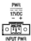
DC Power connector (all models)
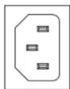
100-240 VAC \~ 50/60 HZ, 3.3A
AC Power connector (NX-4200 only)
FIG. 38 Power connectors
Preparing Captive Wires
You will need a wire stripper and flat-blade screwdriver to prepare and connect the captive wires.
NOTE: Never pre-tin wires for compression-type connections.
- Strip 0.25 inch (6.35mm) of insulation off all wires.
- Insert each wire into the appropriate opening on the connector (according to the wiring diagrams and connector types described in this section).
- Tighten the screws to secure the wire in the connector. Do not tighten the screws excessively, as doing so may strip the threads and damage the connector.
Wiring a Power Connection
To use the 2-pin 3.5mm mini-Phoenix connector with a 12 VDC-compliant power supply, the incoming PWR (+) and GND (-) cables from the external source must be connected to their corresponding locations on the connector (FIG. 39).

flowchart
graph LR
    A["PWR + GND -"] --> B["Power Supply"]
    B --> C["Arrow pointing inward"]
To the rear of the controller
FIG. 39 2-pin mini-Phoenix connector wiring diagram (direct power)
Wiring and Connections
Installation of the USB Gadget Serial Driver for Windows 8.x – 32/64-Bit Operating Systems
Overview
With AMX's NX-Series Controllers, the USB Gadget Serial driver must be installed differently for users running the Windows 8.X 32/64 bit Operating Systems. This driver is necessary for users connecting to the USB programming port on the front panel of the NX-Series Controllers.
Manually installing this driver require you to "Disable Driver Signature Verification" when installing unsigned drivers. The procedures below describe how to disable driver signature verification and how to find the required Gadget Serial driver to install.
Disabling Driver Signature Verification Procedures
Perform the following steps to disable Driver Signature Verification Procedures.
- Press the Win + C keyboard combination to bring up the Charms Bar, then click on the Settings Charm. FIG. 40 displays the Charms bar.
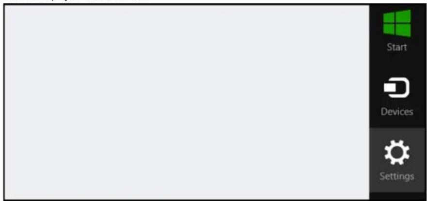
FIG. 40 Charms Bar
- Click on the Change PC settings link.
FIG. 41 displays the available options.
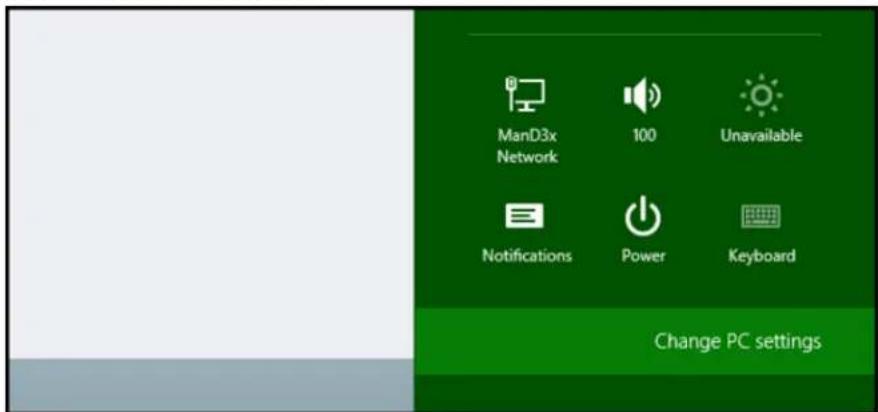
FIG. 41 Change PC Settings
- When the Control Panel opens, select the General section. (Win 8.0 users can skip to step 6.)
FIG. 42 displays the PC Settings options.
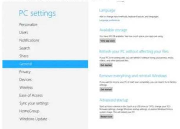
FIG. 42 PC Settings
- When the Control Panel opens, select the Update & recovery option.
FIG. 43 displays the Win 8.1 Control Panel.
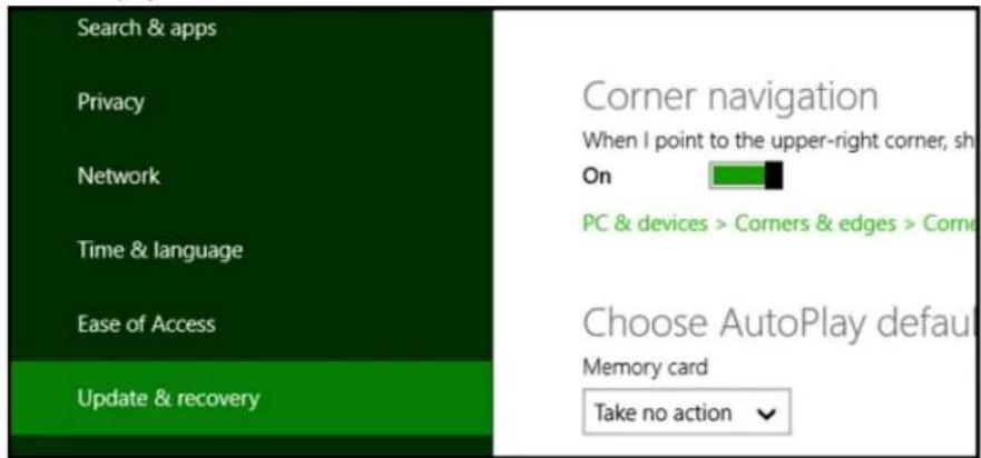
FIG. 43 Win 8.1 Control Panel
- Click on the Recovery option on the left hand side.
FIG. 44 displays the Update and Recovery options.
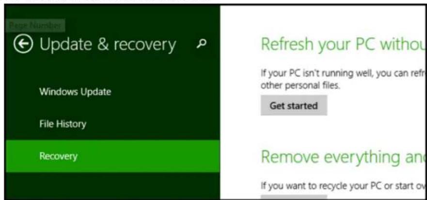
FIG. 44 Update and Recovery options
- Once selected, you will see an Advanced startup section appear. Click on the Restart now button.
FIG. 45 displays the Advanced startup page.
Advanced startup
Start up from a device or disc (such as a USB drive or DVD), change Windows startup settings, or restore Windows from a system image. This will restart your PC.
Restart now
FIG. 45 Advanced Startup page
- Once your PC has rebooted, select the Troubleshoot option.
FIG. 46 displays the Choose an option screen.
Choose an option

Continue
Exit and continue to Windows 8

Troubleshoot
Refresh or reset your PC, or use advanced tools
FIG. 46 Choose an option Screen
-
Select Advanced Options. When the Advanced Options screen appears, select Startup Settings. Since you are modifying Boot Time operations, you must restart your PC again. Click Restart.
-
After your PC restarts, you will see a list of startup settings that you can change. Press F7 to select the "Disable driver signature enforcement" setting.
FIG. 47 displays the Startup Settings screen.
Startup Settings
Press a number to choose from the options below:
Use number keys or functions keys F1-F9.
1) Enable debugging
2) Enable boot logging
3) Enable low-resolution video
4) Enable Safe Mode
5) Enable Safe Mode with Networking
6) Enable Safe Mode with Command Prompt
7) Disable driver signature enforcement
8) Disable early launch anti-malware protection
9) Disable automatic restart after failure
FIG. 47 Startup Settings screen
Your PC will reboot and you will be able to install unsigned drivers without any error messages.
NOTE: You can skip steps 1 - 3 by opening a Command Prompt and entering "shutdown /r /o".
Installing the Gadget Serial Driver
The NetLinx Studio v4.0 setup program installs the Gadget Driver into the Windows\INF directory. After completing the Disabled Driver Signature Verification procedures, use a Type-A-to-Type-B USB cable to connect your PC to the front program port on the NX controller (see FIG. 48). The Windows 8.X Operating System should automatically start searching for the driver on the PC.
FIG. 48 PROGRAM Port
After Windows finds the driver, a Windows Security dialog should open with a "Windows can't verify publisher of this driver software" warning.
Choose the Install the driver software anyway option to finish installing the driver.
When the driver is installed, start NetLinx Studio v4.0. Open the Communications dialog (select Settings | Workspace Communication Settings | Default Settings) and you should see the NX master controller listed on the USB tab (see FIG. 49).
![Communications Settings Current Master Connection USB: NX-2200 - VALOSEKNX2200 [00:60:123456] OK Cancel Recent Network Serial USB Virtual NetLinx Master Available USB Connections Model Host Name Serial Number MAC Address IPv4 Address User Name NX-2200 VALOSEKNX2200 210602x123456 00:60:169.123456 amxuser Select Edit... Select IP Address... Refresh...](/content/2026/05/894413/images/e4b4e2a095f948c69fc461b72c66b189b28171ae58d97e01412ff885d7e4e2ae.jpg)
FIG. 49 Communication Settings dialog - USB tab
Manually Installing/Updating the USB Driver
If you are still having problems with Windows 8.x finding the Gadget Serial driver files, the NetLinx Studio installer will copy a set of the driver files into the following directory:
C:\Program Files (x86)\AMX Control Disc\NetLinx Studio 4\USBGadgetDriver
From the Windows Control Panel, select Hardware and Sound, then select the Device Manager option. You can manually update the driver by performing the following steps:
- Click the Ports branch and select the Gadget Serial driver.
- Right-click Gadget Serial, and select Update Driver Software... from the menu that appears.
FIG. 50 displays the Device Manager dialog.
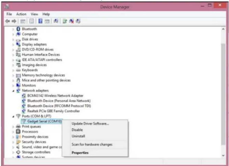
FIG. 50 Device Manager
- In the Update Driver Software dialog that appears, select Browse my computer for driver software, and browse to the following directory:
C:\Program Files (x86)\AMX Control Disc\NetLinx Studio 4\USBGadgetDriver

- IMPORTANT SAFETY INSTRUCTIONS
- COPYRIGHT NOTICE
- LIABILITY NOTICE
- AMX WARRANTY AND RETURN POLICY
- ESD WARNING
- FCC AND CANADA EMC COMPLIANCE INFORMATION:
- EU COMPLIANCE INFORMATION:
- WEEE NOTICE:
- Table of Contents
- Overview 7
- What's New? 8
- Features.... 10
- NX-1200 11
- NX-2200 13
- NX-3200 15
- NX-4200 18
- Mounting the Controller 21
- Wiring and Connections 23
- Overview 23
- Front Panel Components.... 23
- Rear Panel Components 27
- Installation of the USB Gadget Serial Driver for Windows 8.x - 32/64-Bit Operating Systems ....37
- Overview
- Related Documents
- What's New?
- Two Discrete Network Interfaces (NICs)
- Using the ICSLAN Network
- Automatic Binding of AMX Devices on ICSLAN
- Support for IPv6 Networks
- Link-Local Fallback in DHCP Mode
- Wired 802.1X Support
- ID Pushbutton Functionality
- Serial Ports Differences
- Serial, IR, and AxLink Port Diagnostics
- AxLink Power Measurement and Control
- Case Sensitive File System
- USB Program Port
- USB Firmware Upgrade
- USB Program Download
- USB Logging
- Copy and Clone Configuration
- Difference in DEFINE\_PROGRAM Program Execution
- External SD Card Slot (NX-3200 and NX-4200 only)
- Redundant Power Source (NX-4200 only)
- Power Button (NX-4200 only)
- Front Panel LCD Status Display (NX-4200 only)
- 4-Port PoE ICSLAN Switch (NX-4200 only)
- Features
- NX-1200
- Port Numbers
- NX-2200
- NX-3200
- NX-4200
- Other AMX Equipment
- Serial, IR, AxLink, and PoE Port Diagnostics
- Mounting the Controller
- Installing the Controller into an Equipment Rack
- Rack Mount Safety Instructions
- Mounting the NX-1200
- Wiring and Connections
- Front Panel Components
- Power Button
- Program Port
- USB Port
- Status Button
- Front Panel Display
- PoE General Status Format
- PoE Port Status
- LEDs
- General Status LEDs
- 12 General Status LEDs
- ICSLAN LEDs
- SERIAL LEDs
- RELAYS LEDs
- IR/SERIAL LEDs
- I/O LEDs
- IRRX LED
- IRRX Port
- Rear Panel Components
- Serial Ports
- RS-232 Ports
- RS-232/422/485 Ports
- Relay Ports
- Relay Connections
- 23 RELAY connector (male)
- I/O Ports
- 24 I/O ports
- IR/SERIAL Port: Connections and Wiring
- AxLink Port and LED (4-pin captive-wire)
- SDHC Card Slot
- Configuration DIP Switch
- Program Run Disable (PRD) Mode
- ICSLAN Ports
- DHCP Server
- Opening LAN and ICSLAN Sockets from Code
- ID Pushbutton
- Switching to Static or Dynamic IP Addressing.
- Restoring the Controller Settings to the Factory Defaults
- Restoring the Controller's Factory Firmware Image
- LAN 10/100 Port
- IPv4
- IPv6
- INPUT PWR Connector
- Preparing Captive Wires
- Wiring a Power Connection
- Installation of the USB Gadget Serial Driver for Windows 8.x – 32/64-Bit Operating Systems
- Disabling Driver Signature Verification Procedures
- Advanced startup
- Choose an option
- Startup Settings
- 47 Startup Settings screen
- Installing the Gadget Serial Driver
- Manually Installing/Updating the USB Driver
Brand : AMX
Model : NetLinx NX-4200
Category : Regulator