
ALS-LFI120 - Loudspeaker ATLAS - Free user manual and instructions
Find the device manual for free ALS-LFI120 ATLAS in PDF.


| Product Type | Electronically Steerable Line Source Loudspeaker |
| Brand | Atlas (Fohhn) |
| Model | ALS-LFI120 (LFI-120) |
| Driver Configuration | 8 x 4" (100 mm) impregnated neodymium speakers |
| Amplifier | 8 x 100 W Class D (Pure Path Digital PWM) |
| DSP Channels | 8 |
| Frequency Range | 60 Hz - 17 kHz (-10 dB half-space) |
| Maximum SPL (Peak) | 124 dB (1 m, peak, IEC 60268-2) |
| Sensitivity | 106 dB (2.83 V / 1 m, full-space) |
| Horizontal Dispersion | 110° nominal (-6 dB) |
| Vertical Beam Steering | 0° - 90° in 0.1° increments; tilt angle -40° to +40° |
| Housing Material | Aluminum, powder coated |
| Protective Grille | Ball impact resistant metal, same color as enclosure |
| Dimensions (W x H x D) | 130 x 1250 x 120 mm |
| Weight | 8 kg (net, without options) |
| Power Supply | 100 - 240 V AC, 50/60 Hz, with Power Factor Correction |
| Power Consumption | Standby: 5 W, Max: 400 W |
| Audio Inputs | 2 x balanced line inputs (Phoenix terminals, isolated transformers); Input 2 with priority and pilot tone detection |
| Audio Outputs | 2 x Link (Phoenix terminals) |
| Remote Control | Fohhn-Net via NA-11 adapter, controlled by Fohhn Audio Soft software |
| Simulation Software | Integrated beam simulation in Fohhn Audio Soft (Focus Simulation) |
| Safety Class | Protection Class 1 (requires grounded outlet) |
| Environmental Protection | IP? (not specified; intended for dry indoor use) |
| Operating Temperature | 0°C to +40°C |
| Cleaning | Dust with a slightly damp cloth |
| Accessories Included | User manual, mounting brackets optional |
Frequently Asked Questions - ALS-LFI120 ATLAS
User questions about ALS-LFI120 ATLAS
0 question about this device. Answer the ones you know or ask your own.
Ask a new question about this device
Download the instructions for your Loudspeaker in PDF format for free! Find your manual ALS-LFI120 - ATLAS and take your electronic device back in hand. On this page are published all the documents necessary for the use of your device. ALS-LFI120 by ATLAS.
USER MANUAL ALS-LFI120 ATLAS
Electronically Steerable Line Source Systems

User Manual
LFI-120
LFI-220
LFI-350
LFI-450

natural_image
Four metallic vertical bars against a dark background, no text or symbols visibleImportant information:
Linea Focus series models can only be configured using Fohnn Audio Soft. For software handling see separate user instructions.
For connection to a PC, Fohn-Net Adapter NA-11 is required.
Before using your Linea Focus system, please read this manual carefully and keep it for future reference.
0. Important Safety Information
Please read the following safety information carefully before operating the loudspeaker system(s). Keep this information for future reference.

A lightning flash with arrowhead symbol within an equilateral triangle alerts the user to the presence of uninsulated, dangerous voltage within the system enclosure that may be of sufficient magnitude to constitute risk of electric shock.

An exclamation mark within an equilateral triangle alerts the user to important information regarding to safety, maintenance or service.

CAUTION
RISK OF ELECTRIC SHOCK
DO NOT OPEN

Caution: To reduce the risk of electric shock do not remove cover or back. No user-serviceable parts inside. Refer servicing to qualified personnel.
Compliance with safety provisions against fire hazard, risk of electronic shock and injury to personnel.
WARNING! – While Linea Focus systems are in operation, the following safety requirements must be strictly adhered to:
System Installation and Set-up
- To reduce risk of injury, extreme care should be taken when operating the systems near children.
• Make sure that the systems are firmly secured, especially when used with tripod stands. Avoid sloping or unstable surfaces at all times. - Do not use the systems near water (e.g. sinks, swimming pools, or on wet ground).
- Keep the systems free from moisture, dust, lengthy or intensive exposure to sunlight and vibration.
- The systems should not be used near ovens, heaters or other heat-producing equipment, nor should they be exposed to extremely low temperatures.
- The systems should be installed in such a way that optimum ventilation is guaranteed and power outlets are within easy reach.
• Make sure that the systems cannot be tampered with, or fall over, and that no liquids can get into the ventilation slots thus damaging internal components. - Containers with liquid (i.e. glasses) should never be placed on top of the systems
Operation
• Never go below the minimal load impedance of the connected amplifier.
- When used in conjunction with headphones or an external amplifier, these systems can produce volume levels that may potentially damage your hearing. Do not listen at high volume levels for long periods. If you notice any deterioration in your hearing, or whistling in your ears, please consult your doctor.
• While in use, loudspeakers can be damaged through:
a) feedback from microphones
b) continuous high level, high frequency signals from electronic musical instruments
c) distorted, high level signals
d) popping noises that can occur if a device in the set-up is switched on, connected or disconnected while the amplifier is on
Connection and cabling
• Cabling provides the vital link between all the components in an audio installation, from microphones and instruments to loudspeakers. Their function is often underestimated!
- Please ensure that your cabling functions faultlessly.
- When buying cables, please choose tread-resistant cabling with good quality connectors. If required, we can supply appropriate cabling for your loudspeakers.
- Make sure that the distribution for the mains voltage is intact.
- Using isolated or inadequately earthed distributors or power cables is forbidden!
- Care should also be taken when laying cables: For example, an unbalanced cable should not be placed next to a lighting cable, but if necessary it can be laid at right angles in order to minimize the risk of interference.
- All cables should be firmly fixed to the floor using gaffer tape.
- WARNING: No objects should be placed on the system's power cable. Only use intact power cables!
- The system must only be connected to a mains voltage supply that is compatible with the system itself.
- The power cable should be removed if the system is not going to be used for a while. Remove holding the plug, not the actual cable.
• The system should be referred to a qualified service engineer immediately if:
a) The power cable or connector is damaged.
b) A foreign body or liquid has gone into the system interior.
c) The system has been exposed to rain.
d) The system is not working as normal, for instance if significant changes in performance are noticeable.
e) The system has fallen over, or the housing is damaged.
- Do not perform any kind of servicing on the system outside of normal daily maintenance. Any additional servicing must be carried out by suitably qualified service personnel.
- Keep all packaging in case the system needs to be returned for whatever reason. Using the original packaging will minimize any potential risk of damage during transportation.
Contents
- Important Safety Information .... 2
- Introduction......6
- Safety and Environment....6
2.1 Safety precautions....6
2.2 Safety issues 6
2.3 Installation instructions....7
2.4 Environment....7
- Delivery....7
- Cleaning....7
- Description 8
5.1 General 8
5.2 Connection Diagram LFI-120/220/350/450 10
5.3 Internal terminal connections LFI-120/220/350/450.... 10
5.4 Required tools for installation.... 12
5.5 Cable duct.... 13
5.6 Opening the service flap.... 13
5.6.1 Removing the front grille.... 13
5.6.2 Opening the service flap 14
5.6.2 Closing the service flap and replacing the front grille....15
- System set-up.... 17
6.1 Connection 17
6.2 Setting up an address.... 17
- Beam Simulation.... 18
7.1 Where do I find the simulation window? 18
7.2 How do I select my Linea Focus system? 19
7.3 Basic operation....19
7.3.1 Changing values or zooming using the mouse wheel 19
7.3.2 Clicking/holding the left mouse button and dragging the mouse up/down = change values or move the graphic axes....19
7.4 Simulation graphics ...... 20
7.5.1 Position: Position in the room 21
7.5.2 Frequency 21
7.5.3 Angle....21
7.5.4 Beam: vertical inclination angle 21
7.5.5 High pass: High pass for delay applications.... 21
7.5.6 Optimization - FOHHN® SIDE LOBE FREE TECHNOLOGY 22
7.5.7 Gain: Individual beam levels.... 22
7.5.8 Split Beam....23
-
DSP Functions.... 23
-
Workflow 23
9.1 Achieving the best possible speech intelligibility.... 23
- Operation and installation.... 24
10.1 Operating conditions.... 24
10.2 Correct installation.... 24
10.3 Avoiding acoustic feedback.... 24
10.4 LFI input switching und pilot tone detection 24
10.5 System integration in accordance with EN 60849....25
10.6 Protection and maintenance.... 26
10.7 Avoiding interference.... 26
- Technical Data 27
11.1 Technical Data LFI-120 27
11.2 Performance Data LFI-120.... 29
11.3 Technical Data LFI-220 30
11.4 Performance Data LFI-220.... 32
11.5 Technical Data LFI-350....33
11.6 Performance Data LFI-350 35
11.7 Technical Data LFI-450 36
11.8 Performance Data LFI-450....38
-
Accessories for Linea Focus 39
-
1 Accessory Overview.... 39
1. Introduction
Congratulations on the purchase of your Fohhn® Linea Focus loudspeaker system. Today, demands for sound quality and flexibility are higher than ever. With this in mind, we have developed our electronically steerable Linea Focus systems – a loudspeaker series designed to make working at an event or commissioning a fixed installation as straightforward as possible. With an immense range of possibilities offered by our Fohhn Audio DSPs, smooth operation on a daily basis is guaranteed.
Please read through this user manual carefully in order to achieve maximum performance capability from your Fohhn® loudspeaker system, and to ensuring trouble-free operation. We advise keeping this user manual for future reference.
2. Safety and Environment
2.1 Safety precautions
- This system has been assembled and tested in accordance with VDE (German Commission for Electrical, Electronic and Information Technologies) directives regarding electronic devices. It has left the factory in perfect, safe condition. In order to maintain its condition, and to ensure hazard-free operation, please keep general safety requirements in mind and heed any specific advice or warnings given in this user manual.
- This system complies with Protection Class 1 regulations. In a correctly installed situation, all metal parts that can be touched are connected to a protective conductor. On safety grounds, the system should only be connected to an easily accessible, regular earthed socket. The ground of the power cable should never be isolated. The system should never be connected to an unearthed socket.
- This system complies with current EMC regulations, as shown by its CE marking.
- This system does not contain any components that can be repaired by the user. To minimize the risk of burns or electric shock, do not open the housing. Instead, contact a qualified technician regarding the necessary repair.
- Exposure to high levels of sound can damage your hearing! Do not stand directly in front of a system for any length of time when operational. Avoid feedback.
2.2 Safety issues
If the system
• shows visible signs of damage,
- contains loose parts,
• no longer works properly,
• has been stored for a while in unfavourable conditions (e.g. outdoors or in a damp room),
• has been mishandled during transportation (e.g. in unsuitable packaging),
its safety may be compromised. Stop using the system and mark it accordingly. Secure it against any unintentional operation, so that it cannot inadvertently be used by a third party.
2.3 Installation instructions
Installation instructions (commercially available loudspeaker stands, traverses and mounting brackets): To ensure absolute stability, the system must be securely mounted and made safe using the most appropriate method.
2.4 Environment
When the time comes to dispose of this system, separate the housing, electronic components and cables and make sure that all components meet the necessary disposal requirements.
3. Delivery
Your Linea Focus system comprises the following:
1x LFI-120 / LFI-220 / LFI-350 or LFI-450 loudspeaker system 1x User manual
Please check that the package includes all the necessary components belonging to the system. If anything is missing, please contact your Fohnn® reseller.
4. Cleaning
The Linea Focus systems' aluminium housing can be dusted using a slightly damp cloth.
5. Description
5.1 General
Fohnn Linea Focus LFI-120/220/350/450 loudspeakers are electronically steerable line source speakers. Using software, their beam characteristics can be individually adjusted, presenting a whole a range of possibilities for planners and integrators. As a series, Linea Focus offers both elegant design and first-class sound quality.
Linea Focus has been specially developed to guarantee top quality transmission of both speech and music, especially in acoustically challenging venues. In order to unobtrusively integrate into a range of architectural settings, Linea Focus LFI-120/220/350/450 models are equipped with internal connectors and special features that allow for integration into sound systems for emergency purposes in accordance with DIN EN 60849 / VDE 0828. Additionally, they can be connected to the digital network OPTOCORE via optional input extension for MADI over CAT5 and optical fibre. These loudspeaker models are specially optimized for fixed installation applications.
Our aim has been to bring flexibility and precision to this fixed installation loudspeaker series, enabling specific audience areas to be targeted without the speakers themselves having to be moved. The actual beam steering process results from specially developed Fohnn Audio DSPs. Adjusting the beam to suit room conditions is done using Fohnn Audio Soft control software – an intuitive PC interface that enables both beam simulation and real-time adjustment. Other Fohnn® Audio DSP parameters can also be adjusted using the software.
Both the vertical inclination angle and the vertical width of the “acoustic beam” can be set up and adjusted. This results in highly precise coverage of designated audience areas and the minimizing of unwanted room reflections. Levels of speech intelligibility can therefore be greatly improved, even in difficult acoustic conditions.
Linea Focus series models are respectively equipped with 8 (LFI-120), 16 (LFI-220), 24 (LFI-350), and 32 (LFI-450) high performance 4" speakers. Arranged in a column, these speakers are able to produce a highly directional, low reflection, cylindrical beam. Each of the 8/16/24/32 speakers has its own Class D Direct Path DSP 100 W amplifier.
Electronically controlled Beam Steering
Fohnn Audio DSP technology, in combination with Fohnn Audio Soft, enables the vertical inclination angle and vertical width of the “acoustic beam” to be set up without having to physically move the loudspeaker. This gives planners and system integrators increased scope for unobtrusively integrating Linea Focus systems into different types of room architecture.
Initial scientific research into the beam behaviour of loudspeaker arrays began as far back as the 1920s (Literature: Wolfe, I. & Malter, L., "Directional Radiation of Sound", J. Acoustical Society of America, volume 2, number 2, p. 201 (1930). At the time, the corresponding DSP technology did not of course exist.
When using vertically and closely positioned speakers within a housing (i.e. as found in a line source loudspeaker), the overlapping sound sources make vertical compression possible over a wide frequency range. The longer the line length of the speaker, the more precisely frequencies can be targeted, even lower ones. For this reason, Linea Focus models are available in different lengths.
When every single speaker within the line source system can be electronically adjusted, this also influences the directional characteristics of the system, making it possible to “swivel” the acoustic beam. In order to do this however, a highly complex technology is required, especially if the beam characteristics are to be interactively optimized in real time.
TWO BEAM TECHNOLOGY
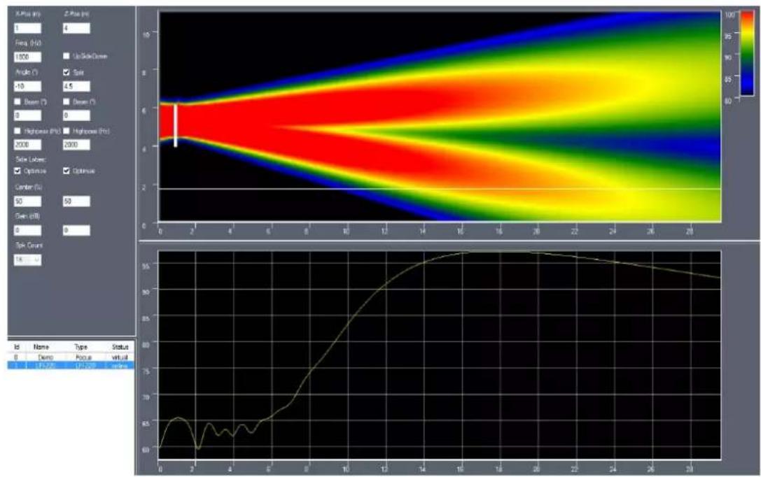
Linea Focus LFI-120/220/350/450 models are also able to generate two independent beams, enabling separate coverage of different audience areas. Asymmetric beams can also be generated.

SIDE LOBE FREE TECHNOLOGY
Fohhn's in-house developed algorithm is designed to suppress unwanted side lobes, reducing the potential occurrence of unwanted reflections.
GREEN POWER STAND BY MODE
The energy-saving Green Power Standby Mode uses a power consumption of just 5 W. Maximum consumption otherwise is 400 W (LFI-120), 800 W (LFI-220), 1200 W (LFI-350) and 1600 W (LFI-450).
5.2 Connection Diagram LFI-120/220/350/450
All connectors are located behind a service flap in the LFI-120/220/350/450 housing, which is accessible from the front of the loudspeaker. Cabling can be fed from the rear of the loudspeaker, though an opening in the housing, and connected to the Phoenix terminals from the front, effectively hiding it from view. An internal strain relief guarantees reliable operation.
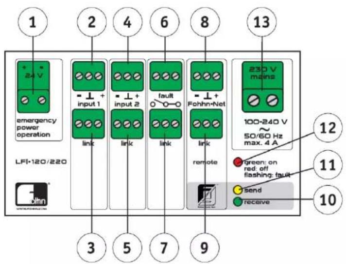
5.3 Internal terminal connections LFI-120/220/350/450
(1) Service sockets for maintenance (for qualified service personnel only!)
(2) Line input ch1
Connect the input signal to this input terminal (2). Input 1 is balanced und isolated.
(3) Link socket ch1
From this output socket, (3) the input signal from Input Channel 1 can be looped through.
(4) Line input ch2 PRIORITY = priority for emergency announcements
Input 2 (4) is equipped with priority switching. As soon as a signal is detected at Input 2, Input 1 is switched off. Input 2 is balanced and isolated.

Inputs 1 and 2 cannot be used at the same time.
(5) Link socket ch2
From this output socket, (5) the input signal from Input Channel 2 can be looped through.

Image: Fohhn® Audio Soft input channels 1 + 2 (Priority)
(12) Status LED
Using Fohn Audio Soft, Linea Focus can be switched to Standby Mode. LED (12) is lit red showing Standby Mode:
• The amplifiers are switched off,
• Power consumption is minimized (energy saving mode),
• The network is active.
When Linea Focus is switched on again, LED (12) is lit green.
If the LED is flashing, this indicates a hardware fault. In this instance please contact the manufacturer service@fohhn.com

(13) Mains terminal
Terminal (13) is for connecting the mains cable. The system must comply with all applicable regulations regarding connection. Only when the power cable has been removed, is the system fully disconnected from the mains.
(14) Earthing screw
This earthing screw (14) is for correct grounding of the Linea Focus system.

Operating this system without grounding is forbidden!
(15) Cable duct with strain relief
This cable duct with strain relief is for the connection cable.
Fohhn-Net Remote – The Fohhn Control Network
(8) Fohhn-Net Remote connection terminals
(9) Network cables are connected to the terminal at (8) and link at (9). See separate user instructions for Fohn Audio DSP software handling!
(10) receive LED
This LED indicates that data is being received by Linea Focus.
(11) send LED
This LED indicates that data is being sent from Linea Focus.
5.4 Tools for installation
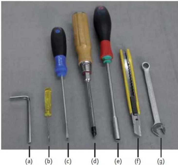
(a) Allen® key 4 mm (for wall brackets)
(b) small screwdriver for Phoenix terminals
(c) screwdriver for opening the front grille
(d) Philips® screwdriver for opening the service flap
(e) 5.5 socket spanner for the 4 strain relief nuts
(f) knife for widening rubber profile slot (if needed)
(g) 8 mm spanner for the earthing screw
5.5 Cable duct
A rear opening in the loudspeaker housing enables all cabling to be fed through. Depending on the cable harness, the slot in the rubber profile can be widened using a knife.

natural_image
Close-up of a yellow tool tiping a dark, rectangular object with a metallic ring (no visible text or symbols)5.6 Opening the service flap
5.6.1 Removing the front grille

natural_image
Close-up of a hand using a tool to cut or mark a curved white object on a textured surface (no text or symbols visible)
natural_image
Close-up of a metallic curved panel or cover with a grid pattern, showing internal structure and alignment lines (no text or symbols visible)notches for screwdrivers
Using a screwdriver, the lower front grille can be carefully prized open from its snap lock closure. Two notches provide appropriate leverage points for the screwdriver. Do this very carefully to avoid risk of damage.
The grille can then be carefully detached from its groove at the base of the loudspeaker.

5.6.2 Opening the service flap

natural_image
Close-up of a white cylindrical device with black perforated interior and labeled parts (1) and (2), no readable text or symbols beyond labels.Carefully remove the two crosshead screws (1) and (2). The service flap can then be removed, and all relevant terminals easily accessed.

5.6.2 Closing the service flap and replacing the front grille
Close the service flap using the crosshead screws (1) and (2) and the tooth lock washers, which are vital for screw retention.

natural_image
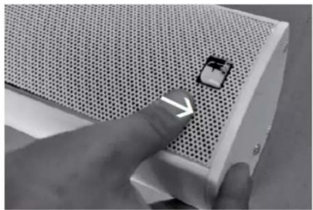
Close-up of a finger pressing a small electronic component on a perforated metal panel (no text or symbols visible)Carefully place the grille in the groove at the base of the loudspeaker then lay it along the housing.

natural_image
Close-up of a white plastic panel with a black vent and a white arrow pointing to it, no visible text or symbols.
natural_image
Close-up of hands installing a grid-patterned panel edge, with a white arrow pointing to the edge (no text or symbols visible)Using both hands and equal pressure, press the grille carefully into its snap lock closure.
6. System set-up
Configuration
Linea Focus systems can only be configured using Fohnh Audio Soft (Version 3 or newer). For connection to a PC, the NA-11 Fohnh-Net Adapter is also required.
6.1 Connection
- Connect to a 110 - 230 V power outlet.
- Make the audio connections.
- Make the network connection using an NA-11 interface (Fohhn-Net).
- Connect the NA-11 interface to a Windows PC.
-
Start Fohn Audio Soft.
-
The Linea Focus system will appear in Fohnn Audio Soft with ID 1 (factory default setting).
If more Linea Focus systems, or other Fohn DSP devices are to be connected, the Linea Focus ID may need to be changed as each address (ID) can only appear once in the network.
6.2 Setting up an address
- Connect the Linea Focus system to an NA-11 interface and PC.
- Start Fohn Audio Soft.
- Open the Device List.
- Click on the "Options" button (in the row where the Linea Focus system with ID 1 is).
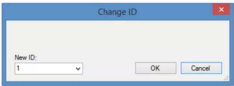
- Click on "Change ID".
- Select an ID and click "OK".
7. Beam Simulation
Fohhn Audio Soft contains an integrated acoustic simulation window that enables Linea Focus systems to be interactively and efficiently set up in real time. Frequency range values and sound pressure levels can be read at the click of a mouse, from any listening position.

7.1 Where do I find the simulation window?
In Fohhn Audio Soft click on "Focus Simulation", this opens the simulation window.

7.2 How do I select my Linea Focus system?
In the left bottom corner you will find a list of connected Linea Focus systems. Click on the system that you want to monitor. On the left side of the simulation window you will see all the data relating to that selected system.
| Id | Name | Type | Status |
| 0 | Demo | Focus | virtual |
| 1 | LFI-220 | LFI-220 | online |

line
| x | y | | ---- | ---- | | 0.0 | 76.5 | | 0.5 | 73.0 | | 1.0 | 73.2 | | 1.5 | 72.8 | | 2.0 | 75.5 | | 2.5 | 78.0 | | 3.0 | 82.0 | | 3.5 | 87.0 | | 4.0 | 91.0 |7.3 Basic operation
All parameters can be easily adjusted using a mouse or computer keyboard. It is also just as easy to zoom in on the graphics, change the scaling of the axes and adjust the colour mapping of the sound pressure levels.
7.3.1 Changing values or zooming using the mouse wheel
- Click in the "Angle (°)" field. Values can be changed using the mouse wheel. Click in the upper graphic display and rotate the mouse wheel. The scale of the view (Zoom) will change. Click in the lower graphic display on the vertical axis labelling. Rotating the mouse wheel will change the resolution.
- Click on the colour legend at the top right of the display and rotate the mouse wheel. The colours seen in the simulation correspond with various sound pressure level values – these can be adjusted as required.
7.3.2 Clicking/holding the left mouse button and dragging the mouse up/down = change values or move the graphic axes
- Click in the "Angle (°)" field.
- Hold down the left mouse button and drag the mouse up or down. The values will change correspondingly.
- Click in the lower display on the vertical axis labelling.
- Hold down the mouse button and drag the mouse pointer up or down. The sound pressure level display moves correspondingly.
- Click on the colour legend at the top right of the display and drag the mouse pointer up or down. The colour display is adjusted correspondingly.
7.4 Simulation graphics
The use of two different graphic displays is designed to make Linea Focus set-up more straightforward.

heatmap
| X | Y | Value | |---|---|-------| | 0 | 0 | 2 | | 1 | 1 | 4 | | 2 | 2 | 3 | | 3 | 3 | 5 | | 4 | 4 | 6 | | 5 | 5 | 7 | | 6 | 6 | 8 | | 7 | 7 | 9 | | 8 | 8 | 10 | | 9 | 9 | 9 | | 10 | 10 | 8 | | 11 | 11 | 7 | | 12 | 12 | 6 | | 13 | 13 | 5 | | 14 | 14 | 4 | | 15 | 15 | 3 | | 16 | 16 | 2 | | 17 | 17 | 1 | | 18 | 18 | 0.5 | | 19 | 19 | 0.25 | | 20 | 20 | 0.125 | | 21 | 21 | 0.0625 | | 22 | 22 | 0.025 | | 23 | 23 | 0.0125 | | 24 | 24 | 0.00625 | | 25 | 25 | 0.003125 | | 26 | 26 | 0.0015625 | | 27 | 27 | 0.00078125 | | 28 | 28 | 0.0003906325 | | 29 | 29 | 0.000195315625 | | 30 | 30 | 0.00009765628125 | | 31 | 31 | 0.000048828190625 | | 32 | 32 | 0.0000244140953125 | | 33 | 33 | 0.00001220704765625 | | 34 | 34 | 0.000006103578878125 | | 35 | 35 | 0.0000030517591945625 | | 36 | 36 | 0.000001575874474728125 | | 37 | 37 | 0.00000078793773731425 | | 38 | 38 | 0.000000398468868668425 | | 39 | 39 | 0.00000019473444483418125 | | 40 | 40 | 0.0000000973677779195625 | | Note: The heatmap values are estimated based on the color scale from the color bar (ranging from ~99 to ~99). The x-axis labels are 'Size (mm)' and 'Time (s)' for the heatmap, and the y-axis labels are 'Position (m)' and 'Time (s)' for the plot.Image: Beam display (above), Frequency range display (below) and Legend (top right)
7.4.1 Beam display
The upper display area shows the Linea Focus beam behaviour. The view is that of a vertical “slice” through the room, with the Linea Focus loudspeaker on the left hand side. Sound pressure levels in the room are displayed using different colours. The legend at the top right of the display enables you to set up the actual sound pressure level range that will be displayed. A right mouse click on the display will show the SPL at that point.
7.4.2 Frequency range display
The lower display area shows the sound pressure level at a listening height of 1.70 metres, which is indicated by the white line in the upper display. The displayed SPL applies to the selected frequency. Moving the mouse in the upper display turns the frequency range in the lower display red at the position of the mouse pointer.
7.4.3 Legend
The legend at the top right of the display shows the colours that correspond to various sound pressure levels. By dragging on the scale, this colour mapping can be adjusted (see 7.3 above).
7.5 Control elements
On the left hand side are the various control fields for setting up the different Linea Focus beam steering parameters.
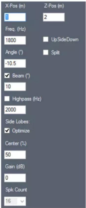
7.5.1 Position: Position in the room
X-Pos = distance of the Linea Focus from left border of display (in metres)
Z-Pos = Height of the Linea Focus from the floor (in metres)
7.5.2 Frequency
This shows the frequency for which the simulation is calculated (in Hertz).
7.5.3 Angle
This is the inclination angle of beam to the horizontal (resolution 0,1 degrees.)
7.5.4 Beam: vertical inclination angle
The vertical inclination angle is dependent on the frequency and the length of the loudspeaker. The angle will not be smaller than the set value.
7.5.5 High pass: High pass for delay applications
Low frequencies can be bypassed.
7.5.6 Optimization - FOHHN® SIDE LOBE FREE TECHNOLOGY
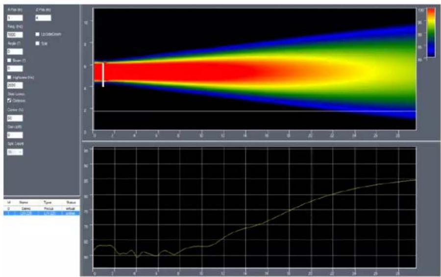
Side Lobe Free optimization enables best possible levels of speech intelligibility to be achieved. A special algorithm minimizes the potential effects of side lobes, resulting in fewer reflections from the beam energy straying in different directions.
heatmap
| Time (min) | BE Value | |------------|----------| | 0 | 50 | | 2 | 45 | | 4 | 40 | | 6 | 35 | | 8 | 30 | | 10 | 25 | | 12 | 20 | | 14 | 15 | | 16 | 10 | | 18 | 5 | | 20 | 0 | | 22 | -5 | | 24 | -10 | | 26 | -15 | | 28 | -20 |Image: Beam without Side Lobes

Image: Beam with Side Lobes
7.5.7 Gain: Individual beam levels
When working with two beams, the levels of each can be separately adjusted.
7.5.8 Split Beam
Switch between one or two beams. If Split Beam is checked, the control fields for the second beam are also shown.
heatmap
| X Range | Y Range | Value | |---------|---------|-------| | 0-2 | 0-2 | 60 | | 2-4 | 2-4 | 70 | | 4-6 | 4-6 | 65 | | 6-8 | 6-8 | 75 | | 8-10 | 8-10 | 85 | | 10-12 | 10-12 | 90 | | 12-14 | 12-14 | 95 | | 14-16 | 14-16 | 98 | | 16-18 | 16-18 | 97 | | 18-20 | 18-20 | 95 | | 20-22 | 20-22 | 93 | | 22-24 | 22-24 | 90 | | 24-26 | 24-26 | 88 | | 26-28 | 26-28 | 85 | | 28-30 | 28-30 | 83 |8. DSP Functions
Please see the Fohnh Audio Soft user instructions.
9. Workflow
9.1 Achieving optimum levels of speech intelligibility
- Use as few loudspeaker systems as possible. Using more loudspeakers will potentially generate more unwanted reflections.
- Keep the beam angle as narrow as possible (5°-10°), i.e. do not mount the LFI system too high.
• Mount LFI models above head height, however. - Enter the mounting height in the simulation (Z-axis (metres)).
- Set a frequency of around 1800 Hz.
- Optimize settings to give the best possible speech intelligibility (reduce Side Lobes).
- Optimize the angle of the beam at the listening position (the white line at 1.70 m).
- Open up the beam (4-10 degrees), so that the front area is well covered. Check the beam characteristics in the simulation at 5000 Hz.
- Check, by measuring and listening, whether the required area is evenly covered. Lack of appropriate optimization can lead to an audible reduction in high frequencies.
Caution: The simulation uses a lot of computing power. To minimize calculation times, especially when using an older computer, it makes sense to work with lower frequencies and to keep the graphic displays small. DSP data is sent immediately to Linea Focus, even if calculation of the graphic simulation has not been fully completed.
10. Operation and installation
10.1 Operating conditions
- The system should be operated in an ambient temperature range of 0^ to +40^ .
- The system can be stored or transported in a temperature range of -10^ to +70^ .
- If moisture builds up on the loudspeaker or its rear panel during transportation or storage, leave the system to acclimatise for approximately 2 hours before using it.
- Linea Focus systems are designed for use in dry surroundings with a normal amount of moisture or dust in the air. Never use abrasive chemical liquids or vapours on the loudspeakers.
- You can use the system in any appropriate environment. However, make sure that the heat dissipation is always controlled by an efficient heat sink behind the lower front grille.
10.2 Correct installation
Installation instructions (commercially available loudspeaker tripod stands, traverses and mounting brackets): To ensure absolute stability, the system must be securely mounted and made safe using the most appropriate method. Please refer to Chapter 12 – Accessories for Linea Focus.
10.3 Avoiding acoustic feedback
When microphones are involved there is a possibility of feedback occurring. This results in a shrill, high-pitched whistling sound from the loudspeakers. To avoid feedback:
- Make sure that the microphone user stands behind the loudspeaker system where possible, in order to avoid generating feedback.
• Make sure that the microphone is not pointing directly at the loudspeaker. - Always hold hand-held microphones by their shaft. The microphone head should not be covered by the user's hand.
- If the loudspeaker does begin to feed back, turn the microphone level down until the feedback stops.
10.4 LFI input switching und pilot tone detection
Input 2 is equipped with a priority circuit and pilot tone recognition.
An input level of > -30 dBV means that the signal will be exclusively transmitted via Input 2. An input level of < -30dBV means that the signal will be transmitted via Input 1. From Firmware 2.12.10, the pilot tone keeps Input 2 active. If the pilot tone and audio signal are switched off, the LFI defaults to Input 1 and will only transmit the signal via this input.
The pilot tone can also be activated in Fohhn® Audio Soft. If the pilot tone is missing, the LFI sends a message via the fault message contact.
Pilot tone frequency: 20 kHz, > -30dBV
Input 2 is also equipped with a low pass filter, operational at 16 kHz / -6 dB, in order to filter the pilot tone.
Using Input 2 without the pilot tone is not recommended as this can lead to fluctuations in level.
Input 1 has no pilot tone recognition and no low pass filter.
10.5 System integration in accordance with EN 60849
Important features for system integration as per DIN EN 60849 / VDE 0828 Regulations on Places of Assembly (sound systems for emergency purposes):
• 2 line inputs with balanced transformers (including pilot tone for redundant use)
- fault message contact for analog evaluation of the operating status
• monitoring and intelligent evaluation of all important device parameters
1. Inputs/Outputs (Phoenix terminals):
Input 1 (standard input without pilot tone monitoring):
• standard line input with high-quality, balanced, isolated input transformer
Input 2 (only for applications with pilot tone monitoring):
- additional line input with pilot tone monitoring and high-quality, balanced, isolated input transformer
- Present pilot tone can be evaluated.
Use with pilot tone, without redundant wiring:
- Input 2 has a higher priority level and is permanently active due to constant pilot tone (> -30dBV).
- In this case input 1 is not in use and remains inactive/muted.
Use with pilot tone and redundant wiring:
- Identical signals for both inputs are required.
- Input 2 has a higher priority level and is permanently active due to constant pilot tone (> -30dBV).
- Input 1 remains muted.
- If the signal to Input 2 – and thus the pilot tone – is interrupted, the signal from Input 1 will be used automatically.
• With an identical audio signal on both inputs, an interruption of the signal is not perceived. - This switchover happens automatically and cannot be configured.
• Therefore redundant wiring is possible.
2. Mains connections 100-240 V / 50/60 Hz:
• 2 pin Phoenix terminal
• grounding screwed
3. Fault message contact:
- pilot tone monitoring
- relay 2x alter
- link terminal
• monitoring of all important device parameters
• intelligent evaluation
The following faults can be monitored and displayed:
- faults relating to the internal voltage supply
• overheating - short-circuit of the amplifier outputs
- shutdown of the amplifier outputs due to earth or voltage problems
- short-circuit of the speaker chassis
- chassis overload (after measuring the impedance, in preparation)
- pilot tone monitoring signal missing from Input 2 (configurable)
• network errors (each message is confirmed)
Fault messages are indicated and displayed via the following:
- fault contact (relay 2x alternate, link)
- red flashing LEDs (built into input circuit board)
• status messages in Fohnn Audio Soft - error messages via RS-485 and Ethernet (accessibility to other systems available)
10.6 Protection and maintenance
To ensure successful operation, do not place the system in bright sunlight, intense heat, damp or dusty environments for any length of time. Avoid operating the system where there is heavy vibration and do not remove the front grille while the system is operational. In the case of any fault or defect, please contact the Service Department at Fohnn Audio AG. Do not attempt to open up the system!
Fohnn Audio AG
Hohes Gestade 3-8
72622 Nürtingen
Germany
Tel. +49 7022 93323-0
Fax +49 7022 93324-0
www.fohhn.com
service@fohhn.com
10.7 Avoiding interference
Do not operate the system in close proximity to radio or TV equipment, as this can cause interference. When connecting other equipment, take care to avoid any unwanted "hum" that might occur.
11. Technical Data
11.1 Technical Data LFI-120
Electro-acoustical features
Acoustic design | electronically steerable line source speaker Components | 8x 4" impregnated speaker membranes (fully neodymium) Operating mode | active, 8-channel x DSP- amplifier, Class-D Sensitivity [4] | 106 dB Power rating (*peak) (1m) [3] | 124 dB Frequency range [5] | 60 Hz- 17 kHz Nominal dispersion, horizontal [6] | 110° Vertical dispersion, electronically steerable | 0°- 90° in 0.1° increments Vertical sound inclination angle, electronically steerable | -40° - +40°
Features
Housing | Aluminium Protective grille | ball impact resistant metal, power coating Suspension points | 8x M6 thread Standard colours | black or white powder coating Front design | metal grille in enclosure colour Dimensions (W x H x D) | 130 x 1250 x 120 mm Weight [7] | 8 kg
Optional features
Optional colours | all RAL colours, Fohhn Texture Design
Electronic performance
Amplifier output | 8x 100 W Amplifier type | Pure Path Digital PWM Audio inputs | 1x standard line input, with balanced transformers, isolated; 1x additional redundant line input, with pilot tone monitoring, prioritized, with balanced transformers, isolated; Optional OPTOCORE Input Extensions: MADI over CAT5 and optical fibre Audio outputs | 2x Link DSP channels, Fohnn Audio DSP | 8 Amplification | 25 dB Input sensitivity | 1.4 V Frequency response | 20 Hz - 20 kHz S/N ratio | >105 dB/A Protective circuit | soft start, temperature monitoring, short-circuit protection, overload Power supply | 100 V - 240 V AC 4 A 50/60 Hz power supply with Power Factor Correction Current consumption | Standby 5 W, max 400 W Low Power | Green Power Standby Mode Temperature range | 0 - 40°C Cooling | temperature-controlled fan Weight, electronics | ca. 2 kg
Remote control, remote monitoring and simulation
Remote control | Fohhn-Net, Fohhn Audio Soft Remote monitoring | temperature, protect, power supply, Fohhn-Net, Fohhn Audio Soft Pilot tone / evacuation system monitoring Fault message contact | Relay 2x alter Simulation beam | Fohhn-Net, Fohhn Audio Soft
Controller
Digital signal processors | 2 Independent limiters | 4 Selective 3-band limiting | bass/ mid/ high Band-specific time constants Filter technology | 56-bit double precision AD | 24 bit/ 96 kHz FIR Filter Gain | -80 dB - +12 dB Volume -80 dB - +12 dB EQ | 10-band parametric EQ, Filter, Gain +/-12 dB, frequency range 10 - 20 kHz, Q 0.1 - 100 limiter, compressor, noise gate X-Over | Linkwitz-Riley 4th order, 24 dB/ octave, high pass 10 Hz - 20 kHz, low pass 10 Hz - 20 kHz Delay | 0.01 - 350 ms or 3.4 mm - 120 m
Connections (built-in Phoenix terminals)
Fohhn-Net | 2x in/thru Phoenix terminals Mains connections | 2 pol Phoenix terminal, grounding screwed Audio inputs | 2x in Phoenix terminals Audio outputs | 2x link Phoenix terminals Fault contact | relay 2x alter, link Phoenix terminals
LED indicators (built in)
Power on/off (standby) | green = on, red = standby, red flashing = fault Network control | receive / send remote control LED
CAAD Simulation data
Simulation data | EASE
[3] peak, 20 ms with bandpass filtered pink noise signal in accordance with IEC 60268-2 at one octave above the lower limit of the frequency range
[4] 2.83 V at 8 Ohms (2 V at 4 Ohms, 4 V at 16 Ohms) at a distance of 1 metre under anechoic full-space conditions
[5] -10 dB under anechoic half-space conditions
[6] horizontal x vertical at -6 dB
[7] net weight without optional components
11.2 Performance Data LFI-120
| U=230VAC | Conditions | Performance Current (A) | Performance Watt ohmsch | Performance VA |
| Standby | 0.08 | 5.3 | 18.5 | |
| Idling time without signal | 0.085 | 6.1^[4] | 20 | |
| Idling time with Signal -50 dBV | 0.12 | 15 | 28 | |
| Maximum mean power [3] | Beam Optimize, Sin 200 Hz | 0.54 | 120 | 124^[4] |
| Maximum mean power | Beam Optimize, Pink Noise | 0.33 | 70 | 76 |
| Maximum mean power | Sin 200 Hz | 0.72 | 150 | 167 |
| Peak power | Sin 200 Hz, 1 s | 1.04 | 230 | 240 |
| Inrush current | without ZCS [1] | 25 A | 1.5 ms | |
| with ZCS | 12 A | 3 ms | ||
| with FZCS [2] | 5 A | < 30 ms |
[1] ZCS = Zero Crossing Switch
[2] FZCS = Fohn Zero Crossing Switch with current limiting
[3] optimized for speech intelligibility in reverberant acoustics (airports, railway stations, stadia ...)
[4] recommended values for calculating energy consumption
The manufacturer reserves the right to make technical modifications according to legal regulations stipulating the continual improvement of product features.
11.3 Technical Data LFI-220
Electro-acoustical features
Acoustic design | electronically steerable line array speaker
Components | 16x 4" impregnated speaker membranes (fully neodym.)
Operating mode | active, 16-channel x DSP- amplifier, Class-D
Sensitivity [4] | 112 dB
Power rating (*peak) (1m) [3] | 130 dB
Frequency range [5] | 60 Hz-17 kHz
Nominal dispersion, horizontal [6] | 110°
Vertical dispersion, electronically steerable | 0°-90° in 0.1° increments
Vertical sound inclination angle, electronically steerable | -40^ - +40^
Acoustic centre of both beams moveable from 0% (bottom of system) to 100% (top of system)
Features
Housing | Aluminium
Protective grille | ball impact resistant metal, power coating
Suspension points | 8x M6 thread
Standard colours | black or white powder coating
Front design | metal grille in enclosure colour
Dimensions (W x H x D) | 130 x 2250 x 120 mm
Weight [7] | 15 kg
Optional features
Optional colours | all RAL colours
Electronic performance
Amplifier output | 16x 100 W
Amplifier type | Pure Path Digital PWM
Audio inputs | 1x standard line input, with balanced transformers, isolated; 1x additional redundant
line input, with pilot tone monitoring, prioritized, with balanced transformers, isolated; Optional
OPTOCORE Input Extensions: MADI over CAT5 and optical fibre
Audio outputs | 2x Link
DSP channels, Fohnn Audio DSP | 16
Amplification | 25 dB
Input sensitivity | 1.4 V
Frequency response | 20 Hz - 20 kHz
S/N ratio | >105 dB/A
Protective circuit | soft start, temperature monitoring, short-circuit protection, overload
Power supply | 100 V - 240 V AC 4 A 50/60 Hz power supply with Power Factor Correction
Current consumption | Standby 5 W, max 400 W
Low Power | Green Power Standby Mode
Temperature range | 0 - 40°C
Cooling | temperature-controlled fan
Weight, electronics | ca. 3 kg
Remote control, remote monitoring and simulation
Remote control | Fohhn-Net, Fohhn Audio Soft
Remote monitoring | temperature, protect, power supply, Fohhn-Net, Fohhn Audio Soft
Pilot tone / evacuation system monitoring
Fault message contact | Relay 2x alter
Simulation beam | Fohn-Net, Fohn Audio Soft
Controller
Digital signal processors | 2
Independent limiters | 4
Selective 3-band limiting | bass/ mid/ high
Band-specific time constants
Filter technology | 56-bit double precision
AD | 24 bit/ 96 kHz
FIR Filter
Gain | -80 dB - +12 dB
Volume -80 dB - +12 dB
EQ | 10-band parametric EQ, Filter, Gain +/-12 dB, frequency range 10 - 20 kHz, Q 0.1 - 100
limiter, compressor, noise gate
X-Over | Linkwitz-Riley 4th order, 24 dB/ octave, high pass 10 Hz - 20 kHz, low pass 10 Hz - 20 kHz
Delay | 0.01 - 350 ms or 3.4 mm - 120 m
Connections (built-in Phoenix terminals)
Fohhn-Net | 2x in/thru Phoenix terminals
Mains connections | 2 pol Phoenix terminal, grounding screwed
Audio inputs | 2x in Phoenix terminals
Audio outputs | 2x link Phoenix terminals
Fault contact | relay 2x alter, link Phoenix terminals
LED indicators (built in)
Power on/off (standby) | green = on, red = standby, red flashing = fault
Network control | receive / send remote control LED
CAAD Simulation data
Simulation data | EASE
[3] peak, 20 ms with bandpass filtered pink noise signal in accordance with
IEC 60268-2 at one octave above the lower limit of the frequency range
[4] 2.83 V at 8 Ohms (2 V at 4 Ohms, 4 V at 16 Ohms) at a distance of 1 metre under anechoic full-space conditions
[5] -10 dB under anechoic half-space conditions
[6] horizontal x vertical at -6 dB
[7] net weight without optional components
11.4 Performance Data LFI-220
| U=230VAC | Conditions | Performance Current (A) | Performance Watt ohmsch | Performance VA |
| Standby | 0.24 | 9.1 | 56 | |
| Idling time without signal | 0.25 | 11^[4] | 60 | |
| Idling time with Signal -50 dBV | 0.28 | 26 | 65 | |
| Maximum mean power [3] | Beam Optimize, Sin 200 Hz | 1.08 | 240 | 248^[4] |
| Maximum mean power | Beam Optimize, Pink Noise | 0.66 | 140 | 152 |
| Maximum mean power | Sin 200 Hz | 1.44 | 300 | 334 |
| Peak power | Sin 200 Hz, 1 s | 2.08 | 460 | 480 |
| Inrush current | without ZCS [1] | 50 A | 1.5 ms | |
| with ZCS | 25 A | 3 ms | ||
| with FZCS [2] | 5 A | < 30 ms |
[1] ZCS = Zero Crossing Switch
[2] FZCS = Fohn Zero Crossing Switch with current limiting
[3] optimized for speech intelligibility in reverberant acoustics (airports, railway stations, stadia ...)
[4] recommended values for calculating energy consumption
The manufacturer reserves the right to make technical modifications according to legal regulations stipulating the continual improvement of product features.
11.5 Technical Data LFI-350
Electro-acoustical features
Acoustic design | electronically steerable line array speaker
Components | 24x 4" impregnated speaker membranes (fully neodym.)
Operating mode | active, 24-channel x DSP- amplifier, Class-D
Sensitivity [4] | 115.5dB
Power rating (*peak) (1m) [3] | 133.5 dB
Frequency range [5] | 60 Hz-17 kHz
Nominal dispersion, horizontal [6] | 110°
Vertical dispersion, electronically steerable | 0°- 90° in 0.1° increments
Vertical sound inclination angle, electronically steerable | -40^ - +40^
Features
Housing | Aluminium
Protective grille | ball impact resistant metal, power coating
Suspension points | 12x M6 thread
Standard colours | black or white powder coating
Front design | metal grille in enclosure colour
Dimensions (W x H x D) | 130 x 3490 x 120 mm
Weight [7] | 25 kg
Optional features
Optional colours | all RAL colours
Electronic performance
Amplifier output | 24x 100 W
Amplifier type | Pure Path Digital PWM
Audio inputs | 1x standard line input, with balanced transformers, isolated; 1x additional redundant
line input, with pilot tone monitoring, prioritized, with balanced transformers, isolated; Optional
OPTOCORE Input Extensions: MADI over CAT5 and optical fibre
Audio outputs | 2x Link
DSP channels, Fohnn Audio DS | 24
Amplification | 25 dB
Input sensitivity | 1.4 V
Frequency response | 20 Hz - 20 kHz
S/N ratio | >105 dB/A
Protective circuit | soft start, temperature monitoring, short-circuit protection, overload
Power supply | 100 V - 240 V AC 4 A 50/60 Hz power supply with Power Factor Correction
Current consumption | Standby 5 W, max 400 W
Low Power | Green Power Standby Mode
Temperature range | 0 - 40°C
Cooling | temperature-controlled fan
Weight, electronics | ca. 5 kg
Remote control, remote monitoring and simulation
Remote control | Fohhn-Net, Fohhn Audio Soft
Remote monitoring | temperature, protect, power supply, Fohhn-Net, Fohhn Audio Soft
Pilot tone / evacuation system monitoring
Fault message contact | Relay 2x alter
Simulation beam | Fohhn-Net, Fohhn Audio Soft
Controller
Digital signal processors | 2
Independent limiters | 4
Selective 3-band limiting | bass/ mid/ high
Band-specific time constants
Filter technology | 56-bit double precision
AD | 24 bit/ 96 kHz
FIR Filter
Gain | -80 dB - +12 dB
Volume -80 dB - +12 dB
EQ | 10-band parametric EQ, Filter, Gain +/-12 dB, frequency range 10 - 20 kHz, Q 0.1 - 100
limiter, compressor, noise gate
X-Over | Linkwitz-Riley 4th order, 24 dB/ octave, high pass 10 Hz - 20 kHz, low pass 10 Hz - 20 kHz
Delay | 0.01 - 350 ms or 3.4 mm - 120 m
Connections (built-in Phoenix terminals)
Fohhn-Net | 2x in/thru Phoenix terminals
Mains connections | 2 pol Phoenix terminal, grounding screwed
Audio inputs | 2x in Phoenix terminals
Audio outputs | 2x link Phoenix terminals
Fault contact | relay 2x alter, link Phoenix terminals
LED indicators (built in)
Power on/ off (standby) | green = on, red = standby, red flashing = fault
Network control | receive / send remote control LED
CAAD Simulation data
Simulation data | EASE
[3] peak, 20 ms with bandpass filtered pink noise signal in accordance with
IEC 60268-2 at one octave above the lower limit of the frequency range
[4] 2.83 V at 8 Ohms (2 V at 4 Ohms, 4 V at 16 Ohms) at a distance of 1 metre under anechoic full-space conditions
[5] -10 dB under anechoic half-space conditions
[6] horizontal x vertical at -6 dB
[7] net weight without optional components
11.6 Performance Data LFI-350
| U=230VAC | Conditions | Performance Current (A) | Performance Watt ohmsch | Performance VA |
| Standby | 0.32 | 14.4 | 74.5 | |
| Idling time without signal | 0.335 | 17.1^[4] | 80 | |
| Idling time with Signal -50 dBV | 0.4 | 41 | 93 | |
| Maximum mean power [3] | Beam Optimize, Sin 200 Hz | 1.62 | 360 | 372^[4] |
| Maximum mean power | Beam Optimize, Pink Noise | 0.99 | 210 | 228 |
| Maximum mean power | Sin 200 Hz | 2,16 | 450 | 501 |
| Peak power | Sin 200 Hz, 1 s | 3,12 | 690 | 720 |
| Inrush current | without ZCS [1] | 75 A | 1,5 ms | |
| with ZCS | 37.5 A | 3 ms | ||
| with FZCS [2] | 5 A | < 30 ms |
[1] ZCS = Zero Crossing Switch
[2] FZCS = Fohn Zero Crossing Switch with current limiting
[3] optimized for speech intelligibility in reverberant acoustics (airports, railway stations, stadia ...)
[4] recommended values for calculating energy consumption
The manufacturer reserves the right to make technical modifications according to legal regulations stipulating the continual improvement of product features.
11.7 Technical Data LFI-450
Electro-acoustical features
Acoustic design | electronically steerable line array speaker
Components | 32 x 4" impregnated speaker membranes (fully neodym.)
Operating mode | active, 32-channel x DSP- amplifier, Class-D
Sensitivity [4] | 118 dB
Power rating (*peak) (1m) [3] | 136 dB
Frequency range [5] | 60 Hz - 17 kHz
Nominal dispersion, horizontal [6] | 110°
Vertical dispersion, electronically steerable | 0°- 90° in 0.1° increments
Vertical sound inclination angle, electronically steerable | -40^ - +40^
Features
Housing | Aluminium
Protective grille | ball impact resistant metal, power coating
Suspension points | 8x M6 thread
Standard colours | black or white powder coating
Front design | metal grille in enclosure colour
Dimensions (W x H x D) | 130 x 1250 x 120 mm
Weight [7] | 32 kg
Optional features
Optional colours | all RAL colours
Electronic performance
Amplifier output | 32x 100 W
Amplifier type | Pure Path Digital PWM
Audio inputs | 1x standard line input, with balanced transformers, isolated; 1x additional redundant
line input, with pilot tone monitoring, prioritized, with balanced transformers, isolated; Optional
OPTOCORE Input Extensions: MADI over CAT5 and optical fibre
Audio outputs | 2x Link
DSP channels, Fohhn Audio DS | 32
Amplification | 25 dB
Input sensitivity | 1.4 V
Frequency response | 20 Hz - 20 kHz
S/N ratio | >105 dB/A
Protective circuit | soft start, temperature monitoring, short-circuit protection, overload
Power supply | 100 V - 240 V AC 4 A 50/60 Hz power supply with Power Factor Correction
Current consumption | Standby 5 W, max 400 W
Low Power | Green Power Standby Mode
Temperature range | 0 - 40°C
Cooling | temperature-controlled fan
Weight, electronics | ca. 2 kg
Remote control, remote monitoring and simulation
Remote control | Fohhn-Net, Fohhn Audio Soft
Remote monitoring | temperature, protect, power supply, Fohhn-Net, Fohhn Audio Soft
Pilot tone / evacuation system monitoring
Fault message contact | Relay 2x alter
Simulation beam | Fohhn-Net, Fohhn Audio Soft
Controller
Digital signal processors | 2
Independent limiters | 4
Selective 3-band limiting | bass/ mid/ high
Band-specific time constants
Filter technology | 56-bit double precision
AD | 24 bit/ 96 kHz
FIR Filter
Gain | -80 dB - +12 dB
Volume -80 dB - +12 dB
EQ | 10-band parametric EQ, Filter, Gain +/-12 dB, frequency range 10 - 20 kHz, Q 0.1 - 100
limiter, compressor, noise gate
X-Over | Linkwitz-Riley 4th order, 24 dB/ octave, high pass 10 Hz - 20 kHz, low pass 10 Hz - 20 kHz
Delay | 0.01 - 350 ms or 3.4 mm - 120 m
Connections (built-in Phoenix terminals)
Fohhn-Net | 2x in/thru Phoenix terminals
Mains connections | 2 pol Phoenix terminal, grounding screwed
Audio inputs | 2x in Phoenix terminals
Audio outputs | 2x link Phoenix terminals
Fault contact | relay 2x alter, link Phoenix terminals
LED indicators (built in)
Power on/off (standby) | green = on, red = standby, red flashing = fault
Network control | receive / send remote control LED
CAAD Simulation data
Simulation data | EASE
[3] peak, 20 ms with bandpass filtered pink noise signal in accordance with
IEC 60268-2 at one octave above the lower limit of the frequency range
[4] 2.83 V at 8 Ohms (2 V at 4 Ohms, 4 V at 16 Ohms) at a distance of 1 metre under anechoic full-space conditions
[5] -10 dB under anechoic half-space conditions
[6] horizontal x vertical at -6 dB
[7] net weight without optional components
11.8 Performance Data LFI-450
| U=230VAC | Conditions | Performance Current (A) | Performance Watt ohmsch | Performance VA |
| Standby | 0.48 | 18.2 | 112 | |
| Idling time without signal | 0.5 | 22^[4] | 120 | |
| Idling time with Signal -50 dBV | 0.56 | 52 | 130 | |
| Maximum mean power [3] | Beam Optimize, Sin 200 Hz | 2.16 | 480 | 496^[4] |
| Maximum mean power | Beam Optimize, Pink Noise | 1.32 | 280 | 304 |
| Maximum mean power | Sin 200 Hz | 2.88 | 600 | 668 |
| Peak power | Sin 200 Hz, 1 s | 4.16 | 920 | 960 |
| Inrush current | without ZCS [1] | 100 A | 1,5 ms | |
| with ZCS | 50 A | 3 ms | ||
| with FZCS [2] | 5 A | < 30 ms |
[1] ZCS = Zero Crossing Switch
[2] FZCS = Fohn Zero Crossing Switch with current limiting
[3] optimized for speech intelligibility in reverberant acoustics (airports, railway stations, stadia ...)
[4] recommended values for calculating energy consumption
The manufacturer reserves the right to make technical modifications according to legal regulations stipulating the continual improvement of product features.
12. Accessories for Linea Focus
WAL-1
Angled wall bracket for Linea Focus LFI-120/220

WLF-1
Wall bracket for Linea Focus LFI-120/220/350*/450*
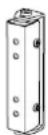
WLF-2
Wall bracket for Linea Focus LFI-120/220/350*/450*

* To ensure safe mounting of LFI-350/450 systems, 2x WLF-1/2 brackets must be used with each system
12.1 Accessory Overview
| WAL-1 | WLF-1 | WLF-2 | |
| LFI-120 | x | x | x |
| LFI-220 | x | x | x |
| LFI-350 | x^* | x^* | |
| LFI-450 | x^* | x^* |
* To ensure safe mounting of LFI-350/450 systems, 2x WLF-1/2 brackets must be used with each system
Fohnn Audio AG
Hohes Gestade 3-8
72622 Nürtingen
Germany
Tel. +49 7022 93323-0
Fax +49 7022 93324-0
www.fohhn.com
info@fohhn.com
Fohnn on Social Media


DB0061X 02/16
- User Manual
- Important information:
- Important Safety Information
- CAUTION
- System Installation and Set-up
- Operation
- Connection and cabling
- Contents
- Introduction
- Safety and Environment
- Safety precautions
- Safety issues
- If the system
- Installation instructions
- Environment
- Delivery
- Cleaning
- Description
- General
- Electronically controlled Beam Steering
- TWO BEAM TECHNOLOGY
- SIDE LOBE FREE TECHNOLOGY
- GREEN POWER STAND BY MODE
- Connection Diagram LFI-120/220/350/450
- Internal terminal connections LFI-120/220/350/450
- Status LED
- Mains terminal
- Earthing screw
- Operating this system without grounding is forbidden!
- Cable duct with strain relief
- Tools for installation
- Cable duct
- Opening the service flap
- Removing the front grille
- Closing the service flap and replacing the front grille
- System set-up
- Configuration
- Connection
- Setting up an address
- Beam Simulation
- Where do I find the simulation window?
- How do I select my Linea Focus system?
- Basic operation
- Changing values or zooming using the mouse wheel
- Clicking/holding the left mouse button and dragging the mouse up/down = change values or move the graphic axes
- Simulation graphics
- Beam display
- Frequency range display
- Legend
- Control elements
- Position: Position in the room
- Frequency
- Angle
- Beam: vertical inclination angle
- High pass: High pass for delay applications
- Optimization - FOHHN® SIDE LOBE FREE TECHNOLOGY
- Gain: Individual beam levels
- Split Beam
- DSP Functions
- Workflow
- Achieving optimum levels of speech intelligibility
- Operation and installation
- Operating conditions
- Correct installation
- Avoiding acoustic feedback
- LFI input switching und pilot tone detection
- System integration in accordance with EN 60849
- Important features for system integration as per DIN EN 60849 / VDE 0828 Regulations on Places of Assembly (sound systems for emergency purposes):
- Inputs/Outputs (Phoenix terminals):
- Mains connections 100-240 V / 50/60 Hz:
- Fault message contact:
- Protection and maintenance
- Fohnn Audio AG
- Avoiding interference
- Technical Data
- Technical Data LFI-120
- Electro-acoustical features
- Features
- Optional features
- Electronic performance
- Remote control, remote monitoring and simulation
- Controller
- Connections (built-in Phoenix terminals)
- LED indicators (built in)
- CAAD Simulation data
- Technical Data LFI-220
- Performance Data LFI-220
- Technical Data LFI-350
- Performance Data LFI-350
- Technical Data LFI-450
- Performance Data LFI-450
- Accessories for Linea Focus
- Accessory Overview
Brand : ATLAS
Model : ALS-LFI120
Category : Loudspeaker