KEY-288+ - DJ Equipment Omnitronic - Free user manual and instructions
Find the device manual for free KEY-288+ Omnitronic in PDF.


| Product Type | DJ Controller/Mixer |
| Model | KEY-288+ |
| Brand | Omnitronic |
| Dimensions (W x D x H) | 480 mm x 300 mm x 100 mm |
| Weight | 5.0 kg |
| Power Supply | 100-240 V AC, 50/60 Hz, 15 W |
| Number of Channels | 4 |
| Built-in Effects | Yes (reverb, delay, filter, flanger) |
| USB Audio Interface | 2-in/4-out, 24-bit/96 kHz |
| Microphone Input | 1x XLR/TRS combo, +48V phantom power |
| Headphone Output | 1x 1/4" TRS, dedicated cue |
| Main Output | 1x XLR (balanced), 1x RCA (unbalanced) |
| Crossfader | Alps, replaceable |
| Display | 2.8" TFT color screen |
| MIDI Control | USB-MIDI, assignable |
| Software Included | Compatible with Serato DJ Lite, Virtual DJ |
| Cleaning and Maintenance | Use dry, lint-free cloth; avoid solvents |
| Safety Precautions | Do not expose to moisture or heat; use only included power adapter |
| Spare Parts and Repairability | Replaceable faders, knobs, and power supply; contact Omnitronic support |
Frequently Asked Questions - KEY-288+ Omnitronic
User questions about KEY-288+ Omnitronic
0 question about this device. Answer the ones you know or ask your own.
Ask a new question about this device
Download the instructions for your DJ Equipment in PDF format for free! Find your manual KEY-288+ - Omnitronic and take your electronic device back in hand. On this page are published all the documents necessary for the use of your device. KEY-288+ by Omnitronic.
USER MANUAL KEY-288+ Omnitronic
KEY-288+
MIDI CONTROLLER
Bedienungsanleitung
User Manual
Inhalt
1 Einführung 2
natural_image
Black MIDI controller with various keyboard keys and control knobs, labeled with numbers 16–19 (no readable text beyond labels)natural_image
Illustration of a MIDI controller connected to a laptop (no text or symbols present)5.2 Mobile Geräte
5.3 Android-Geräte
natural_image
Illustration of a Kiko keyboard connected to an audio workstation via a power cord (no text or symbols visible)8.1.1 Session-Modus
8.1.4 Stop, Solo, Mute
natural_image
Four purple square buttons labeled 5, 6, 7, and 8, each with a glowing pink glow (no additional text or symbols)1 Introduction 25
1.1 Product features 25
1.2 Package contents 25
2 Safety Instructions 26
3 Protecting the Environment ..... 26
4 Operating Elements and Connections 27
5 Making the Connections ..... 28
6 Parts and Their Functions ..... 29
7 Basic MIDI Control 30
7.1 MIDI control messages 30
7.2 Programming controls 30
7.3 Control assignment 30
7.4 Assignable Knobs 31
7.5 Assignable sliders 31
7.6 Pad ▶ote setting.... 32
7.7 Keyboard Velocity curve 32
7.8 Pad velocity 33
7.9 Octave +/- 33
7.10 •ranspose 34
7.11 Program change.... 34
7.12 MIDI channel 34
7.13 Select the backlit RGB color of the 8 pads .... 35
7.14 Other settings 36
8 Use with a DAW 37
8.1 Using Ableton Live 37
8.2 Working with other sequencers ..... 46
9 Technical Specifications .... 47
10 Appendix 47
www.omnitronic.de
For product updates, documentation, software and support please visit www.omnitronic.de. You can find the latest version of this user manual in the product's download section.
© 2022 OM▶I•RO▶IC. All rights reserved.
▶ o part of this document may be reproduced in any form without the written permission of the copyright owner. ●he contents of this document are subject to revision without notice due to continued progress in methodology, design, and manufacturing.
All trademarks mentioned herein are the property of their respective owners.
D00144782, version 1.0, publ. 29/11/2022
1 Introduction
Welcome to Omnitronic! •hank you for choosing one of our products.
- his user manual will show you how to install and operate the controller. Users of this product are recommended to carefully read all warnings in this manual and on the unit in order to protect yourself and others from damage.
Please save this document for future needs and pass it on to further owners.
1.1 Product features
- USB MIDI keyboard for creative music production with PC and Mac or DJ sets
- Super portable format fits laptop bags or backpacks
- Works with virtually any audio software
- 25 velocity-sensitive mini keyboard keys, with 3 velocity curves and one constant velocity
- 8 backlit, velocity-sensitive drum pads can send note, MIDI CC or program change
• 4 freely assignable rotary controls
• 4 freely assignable faders - Brilliant OLED display for immediate parameter setting
- 2 touch sensors of dynamic pitch bend and modulation touch strips
- Standard sustain pedal jack, compatible with switch pedals
- Fixed Chord mode
- 1 Value dial (Enter button: push to enter)
- Play and record transport control buttons
- Powerful and creative Arpeggiator for generating ideas quickly
- Custom modes for user-defined mappings of knobs, sliders and pads
- Connect to your hardware with a standard 3.5mm ●RS MIDI Out jack
- Compatible with iOS by using the Apple iPad Camera Connection Kit (sold separately)
- Ableton Live integration - Launch clips and scenes, play instruments and Drum Racks, capture MIDI, and more
- Integration with other DAWs (Apple Logic Pro X, Propellerhead's Reason etc.)
1.2 Package contents
- KEY-288+
- USB cable
- MIDI cable
2 Safety Instructions
- Please read these operating instructions carefully before using the product. •hey contain important information for the correct use of your product. Please keep them for future reference.
- the KEY-288+ is a handy MIDI controller for music software on PC and Mac. It is powered via the computer's USB port, eliminating the need for a cumbersome power adapter.
- Only use the product according to the instructions given herein, to avoid accidental injury or damage.
- We do not assume any liability for material and personal damage caused by improper use or non-compliance with these operating instructions. In such cases, the warranty/guarantee will be null and void.
- Unauthorized rebuilds or modifications of the product are not permitted for reasons of safety and render the warranty invalid.
- •his product is intended for indoor use only. Protect it from extreme temperatures, direct sunlight, strong jolts, high humidity, moisture, flammable gases, vapors and solvents. •he recommended temperature range is -5 to +45 °C.
- Cleaning of the product is limited to the surface. Make sure that moisture does not come into contact with any areas of the terminal connections or voltage control parts. Only wipe off the product with a dry, lint-free cloth. Before cleaning, disconnect the product from the mains.
- If this product is no longer working properly or is visibly damaged, take it out of operation and consult your local dealer. Do not attempt to repair the product yourself.
- Handle the product with care; it can be damaged by impacts, blows, or accidental falls, even from a low height.
- •his product is not a toy. Keep it out of the reach of children and pets. Do not leave packaging material lying around carelessly.
3 Protecting the Environment
Disposal of old equipment
When to be definitively put out of operation, take the product to a local recycling plant for a disposal which is not harmful to the environment. Devices marked with this symbol must not be disposed of as household waste. Contact your retailer or local authorities for more information. Remove any inserted batteries and dispose of them separately from the product.
4 Operating Elements and Connections
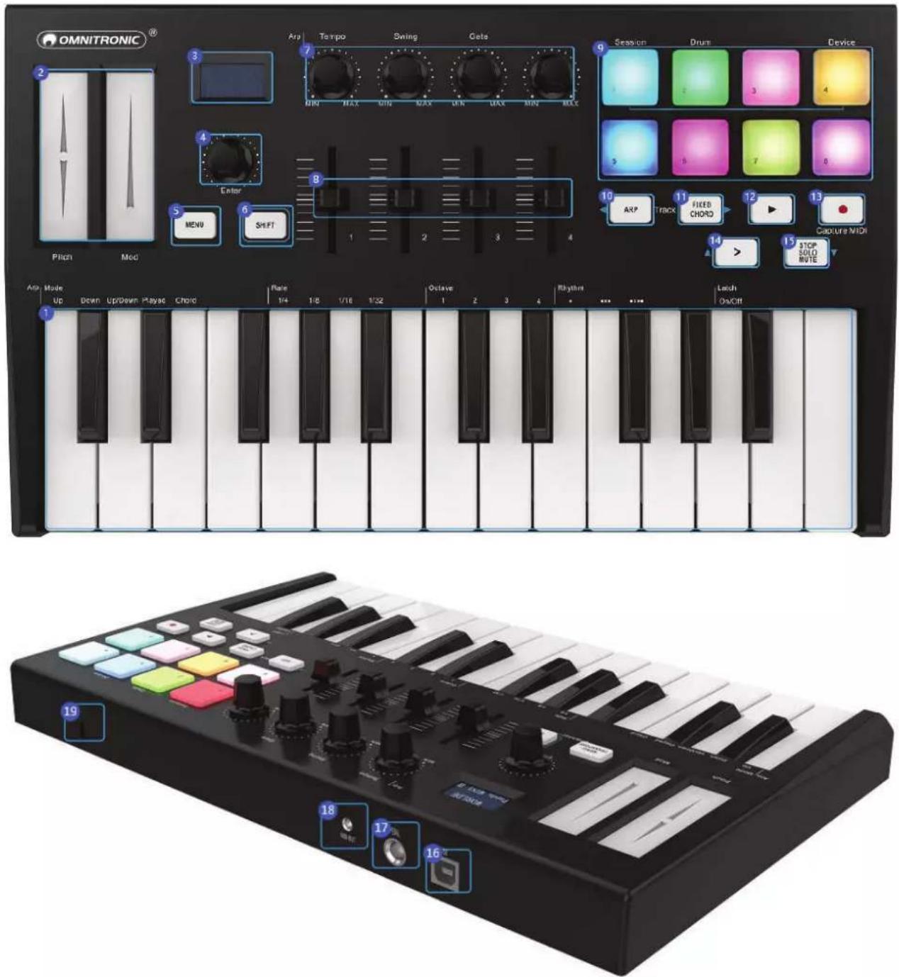
| No. | Element No. Element | ||
| 1 | Keyboard 10 Arp button | ||
| 2 | Modulation strips 11 Fixed Chord button | ||
| 3 | OLED display 12 | ▶Playback button | |
| 4 | Value dial 13(push = Enter) | • Record button | |
| 14 | > Scene Launch button | ||
| 5 | MENU button 15 Stop/Solo/Mute/Enter button | ||
| 6 | SHIFT button 16 USB port | ||
| 7 | Knobs 17 Sustain Pedal jack | ||
| 8 | Sliders 18 3.5mm TRS MIDI Out port | ||
| 9 | Trigger pads with RBG illumination 19 Kensington security lock | ||
5 Making the Connections
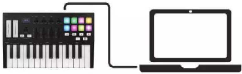
5.1 Computer
- he controller is bus-powered, so it turns on as soon as you connect it to your computer with a USB cable.
natural_image
Illustration of a MIDI controller connected to a laptop via cable (no text or symbols)5.2 Mobile devices
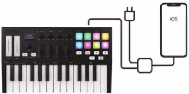
- o operate the controller with an iOS device, use Apple's Lightning to USB 3 Camera Adapter with a separate 2.4A Lightning charger.
5.3 Android devices
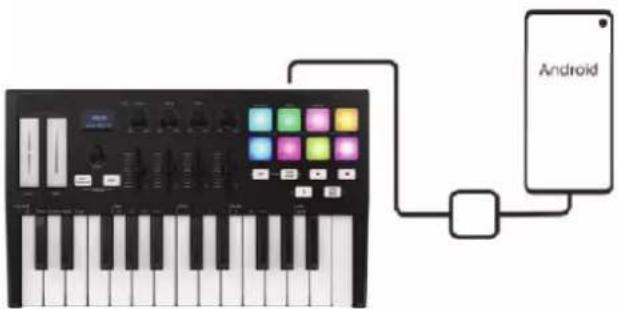
- o operate the controller with an Android device we'd like to recommend a USB O•G to USB adapter.
5.4 Use as a stand-alone MIDI Controller
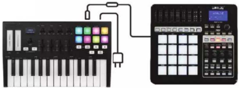
- he 3.5mm ●RS MIDI Out port can be used to connect the controller to a hardware sequencer, an external synthesizer or sound module. A 3.5mm ●RS MIDI Out to MIDI DI▶ adaptor is included. If you want to use the 3.5mm ●RS MIDI output on the controller without a computer, you can power the unit with standard USB power.
natural_image
Illustration of a Kiko keyboard connected to an audio workstation via a power cord (no text or symbols visible)6 Parts and Their Functions
| Element Function | |
| Keyboard | When you play the keyboard, MIDI note messages are sent. These messages are read by your computer software or external MIDI gear and used to generate sound accordingly. The sound played by the keyboard is from your computer software or external MIDI gear. With the MENU button and value dial it's possible to adjust the keyboard velocity curve, octave, transpose, channel, program change etc. More details can be found in chapter 7. |
| Trigger pads | The 8 RGB pads can transmit MIDI note messages. With the MENU button and value dial it's possible to adjust the pad velocity curve, MIDI note number, RGB color of the pad backlight etc. More details can be found in chapter 7. |
| Knobs | The 4 knobs can transmit control change messages. It can be assigned to control any editable parameter on the selected device. More details can be found in chapter 7. |
| Sliders | The 4 sliders can transmit control change messages. It can be assigned to control any editable parameter on the selected device. More details can be found in chapter 7. |
| Pitch and Modulation touch strips | Pitch bend and modulation are activated by pressing the touch strips. If you touch the pitch bend strip at its center and move your finger forward or backward it will alter the pitch of the played sound. Similarly, moving your finger along the Modulation strip alters the modulation amount of the played sound. |
| OLED display | The display is for immediate parameter setting. |
| Value dial (push = enter) | This dial is used for incrementing and decrementing presets, parameter values and settings. This dial also functions as an ENTER button when it is pressed down. Holding the "Enter" button for 2 seconds to exit the edit mode and return to parameter display mode. Then if you rotate the knobs, move the sliders or trigger the pads the display will show the current parameters of these controllers. |
| MENU button | Press MENU to select the following functions: Octave, Velocity curve, Pad velocity, Store all parameters, Recall all parameters, MIDI channel, Program change, Control assign, Transpose, Pad color R, Pad color G, Pad color B, Reset all, CC NUM/Pad note Controller value. |
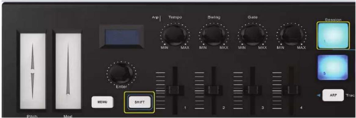
| SHIFT button | Press SHIFT and other buttons at the same time to access secondary functions. Shift is used to select the pads which are great for triggering clips in Ableton Live's Session View and playing drums. Holding SHIFT lights up the top row of pads. You can then switch between the 2 pad modes: Session = For triggering clips and navigating Live's Session View. Drum = For playing drums with the velocity-sensitive pads. |
| Arp button | Press the ARP button to activate the Arpeggiator of the controller. |
| Fixed Chord button | While holding the FIXED CHORD button, press and release the keys that you wish to be part of the stored 'fixed' chord. It only works when connected with Ableton Live. |
| ►Playback button | This button controls your DAW's playback. |
| • Record button | The Record button starts the recording process in your DAW. |
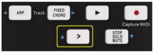
| > Scene Launch button | Pressing SHIFT and the Scene Launch button (>) launches scenes in Ableton Live. This means that all of the clips in a row can start together. It only works when connected with Ableton Live. |
| Stop/Solo/Mute button | Stop/solo/mute: Press this button to switch the functionality of the bottom 8 pads. It only works when connected with Ableton Live. |
| USB port | Connect the controller to your computer with a USB cable via this port. |
| Sustain Pedal jack | The footswitch jack functions as sustain pedal interface. Note: The default setting for footswitch jack is open meaning that pressing the pedal will function as sustain. If it's without sustain function when pressed, it means that the pedal polarity is opposite, so it needs to adjust the polarity by moving the pedal polarity switch to the other end. |
| MIDI output | The 3.5mm TRS MIDI Out port can be used to connect the controller to a hardware sequencer, an external synthesizer or sound module. 3.5mm TRS MIDI Out to MIDI DIN adaptor is included. |
7 Basic MIDI Control
7.1 MIDI control messages
- here are 135 MIDI controller messages that are used for controlling the MIDI-adjustable parameters in your software or on your external MIDI gear (0 to 127 is the standard MIDI control parameter, 128 to 134 is the special MIDI control parameter). Examples of these controllable parameters include volume, pan, expression, reverb, chorus and portamento. - he 8 assignable knobs/sliders and 8 assignable pads on your controller are able to send any of the 128 standard MIDI controller messages to control such parameters. Please note that in order for these effects to work, the MIDI device you are sending to must be able to receive these messages. A full list of these control messages is given in the Appendix from page 47.
For example, you may want to set Knob1 to control the channel volume. ●his is done by assigning controller 7 to Knob1 (first on the left). Examples of other popular effects are listed in the table below. (Please consult the Appendix from page 47 for the full list.)
| Effect Control | |
| Modulation 1 | |
| Volume 7 | |
| Pan | 10 |
| Expression 11 | |
| Reverb depth | 91 |
| Chorus depth | 93 |
- here are many different types of virtual instruments available and most of these respond to MIDI controller messages, allowing you to control a variety of parameters from your controller. Please review the manual that came with your software or external gear to see what these controller numbers are.
7.2 Programming controls
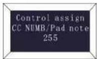
When programming a physical controller, the controller that was last used will be the first one selected for programming. ●o select a different physical controller for programming, the method is: Press the ME▶U button repeatedly until the display reads “Control assign CC ▶UMB/Pad note”, then move the physical controller you wish to program. When control assignment mode works, the display is shown on the left.
7.3 Control assignment
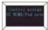
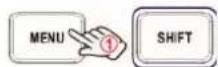
In control assignment mode the 8 assignable knobs/sliders and 8 assignable pads can be programmed to any MIDI controller messages that are used for controlling the MIDI-adjustable parameters in your software or on your external MIDI gear. ●o select a different physical controller for programming, the method is: Press the ME▶U button repeatedly until the display reads "Control assign CC ▶UMB/Pad note", then move the physical controller you wish to program. Input the desired controller value with the value dial and confirm the value with the "Enter" button. Hold the "Enter" button for 2 seconds to exit the edit mode. ●he display is as shown on the left.
7.4 Assignable Knobs
flowchart
graph TD
    A["Control assay EC NUMBER/Pad note"] --> B["Control assay EC number 042 Base"]
    C["Enter"] --> D["③"]
    D --> E["④"]
    E --> F["②"]
    F --> G["MIN MAX MIN MAX"]
    H["MENU"] --> I["1"]
    I --> J["SHIFT"]
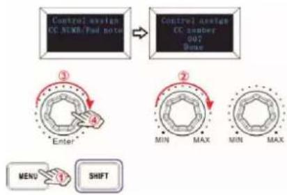
- here are 4 knobs that can be assigned as controller ▶o. independently. Press the ME▶U button repeatedly until the displays reads “CC ▶UMB/Pad note”, then rotate the knobs you wish to program. Input the desired controller value with the value dial and confirm the value with the “Enter” button.
For example, you may want to set Knob1 to control the channel volume. ●his is done by assigning controller 7 to Knob1 (first on the left). ●he operating steps and the display are shown on the left.
(1) Press the ME▶U button repeatedly until the displays reads "Control assign CC ▶UMB/Pad note".
(2) Rotate R1 knob (first on the left).
(3) Rotate the value dial until the displays reads "007". •he numbers are the controllers.
(4) Press the "Enter" button to confirm and the display shows "Done". Hold the "Enter" button for 2 seconds to exit the edit mode and return to parameter display mode. ●hen if you rotate the knobs, move the sliders or trigger the pads the OLED will display the current parameters of these controllers.
7.5 Assignable sliders
flowchart
graph TD
    A["Control assignment CC NUMBER/Pad note"] --> B["Control assignment CC number 0-11 Bone"]
    B --> C["Enter"]
    C --> D["SHIFT"]
    D --> E["MENU"]
    E --> F["1"]
    F --> G["2"]
    G --> H["1"]
    H --> I["2"]
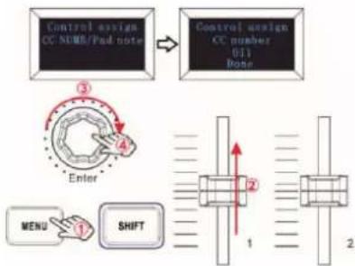
- here are 4 sliders that can be assigned as controller ▶o. independently. Press the ME▶U button repeatedly until the displays reads “CC ▶UMB/Pad note”, then move the sliders you wish to program. Input the desired controller value with the value dial and confirm the value with the “Enter” button.
For example, you may want to set Slider F1 to control the expression control. ●his is done by assigning controller 11 to F1 (first on the left). ●he operating steps and the display are shown on the left.
(1) Press the ME▶U button repeatedly until the displays reads "Control assign CC ▶UMB/Pad note".
(2) Move the F1 slider (first on the left).
(3) Rotate the value dial until the displays reads "011". •he numbers are the controllers.
(4) Press the "Enter" button to confirm and the display shows "Done". Hold the "Enter" button for 2 seconds to exit the edit mode and return to parameter display mode. ●hen if you rotate the knobs, move the sliders or trigger the pads the display will show the current parameters of these controllers.
7.6 Pad Note setting
flowchart
graph TD
    A["Control assign CC NUMBER/Pad note"] --> B["Control assign CC number 034 none"]
    B --> C["Enter"]
    C --> D["Menu 1 SHIFT"]
    D --> E["1 2 3 4"]
    E --> F["5 6 7 8"]
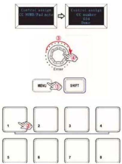
- here are 8 pads that can be assigned to transmit MIDI note messages (drums, stabs, bass notes, whatever). Press the ME▶U button repeatedly until the display reads "CC ▶UMB/Pad note", then trigger the pads you wish to program. Input the desired MIDI note messages with value dial and confirm the value with the "Enter" button. Hold the "Enter" button for 2 seconds to exit the edit mode.
For example, you may want to set Pad 1 to transmit note message 34. •his is done by assigning controller 34 to Pad 1. •he operating steps and the display are shown on the left.
(1) Press the ME▶U button repeatedly until the display reads "Control assign CC ▶UMB/Pad note".
(2) ●rigger Pad 1.
(3) Rotate the value dial until the display reads "34". ●he numbers are the controllers.
(4) Press the "Enter" button to confirm and the display shows "Done". Hold the "Enter" button for 2 seconds to exit the edit mode and return to parameter display mode. ●hen if you rotate the knobs, move the sliders or trigger the pads the display will show the current parameters of these controllers.
7.7 Keyboard Velocity curve
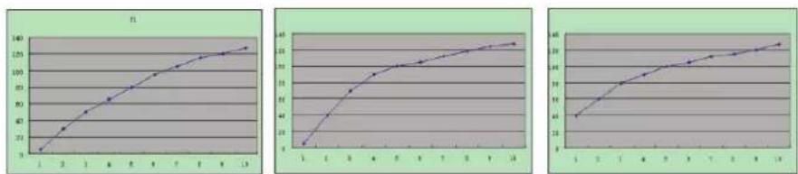
Every time you press a key, a MIDI note message is sent with a velocity value between 0 and the maximum; this value specifies how hard you pressed the key. Since different people have different playing styles, your controller offers 3 different velocity curves and 1 one constant velocity as shown below. ●he default is the first one. You should experiment with the different velocity curves to seek the curve that best suits your playing style.
Keyboard Velocity Curves:
line
| X | F1 | |---|---| | 1 | 0 | | 2 | 25 | | 3 | 50 | | 4 | 75 | | 5 | 100 | | 6 | 115 | | 7 | 125 | | 8 | 130 | | 9 | 135 | | 10 | 140 | | 11 | 145 | | 12 | 150 | | 13 | 155 | | 14 | 160 |- o change the keyboard velocity curve:
flowchart
graph TD
    A["Velocity Curve 000"] --> B["Velocity Curve 002"]
    B --> C["Dose"]
    D["Enter"] --> E["MENU"]
    E --> F["SHIFT"]
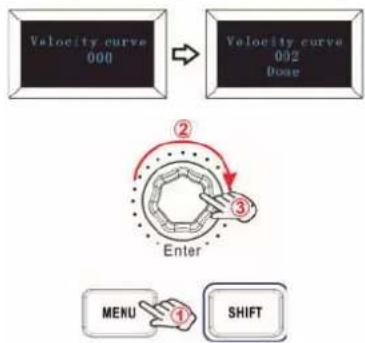
Press the ME▶U button repeatedly until the displays reads "Velocity curve" to start the function of selecting keyboard velocity curve. When this function is valid, the display reads the "Velocity curve" and the ▶umber of the current velocity curve. It can be adjusted via the value dial and confirmed by the Enter button. ●he initial value is 1, adjusting scale is 1\~4. ●he operating steps and the display are shown on the left.
(1) Press the ME▶U button repeatedly until the displays reads "Velocity curve".
(2) Rotate the value dial to adjust the keyboard velocity curve, the display shows the current selected velocity curve.
(3) Press the "Enter" button to confirm and the display shows "Done". Hold the "Enter" button for 2 seconds to exit the edit mode and return to parameter display mode. ●hen if you rotate the knobs, move the sliders or trigger the pads the display will show the current parameters of these controllers.
7.8 Pad velocity
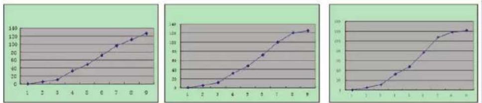
- he Pad Curve setting is used to set the response curve of all 8 pads. It is not possible to set the response curve of the pads independently. Your controller offers 3 different pad velocity curves and 1 one constant velocity as shown below. -he third one is the constant velocity with the value 127.
Pad velocity curves:
To change the pad velocity curve:
flowchart
graph TD
    A["Pad Velocity 009"] --> B["Pad Velocity 002 Bone"]
    B --> C["Enter"]
    C --> D["NENU"]
    C --> E["SHIFT"]
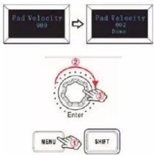
Press the ME▶U button repeatedly until the displays reads "Pad curve" to start the function of selecting pad velocity curve. When this function is valid, the display shows the "Pad velocity" and the ▶umber of the current pad velocity curve. It can be adjusted via the value dial and confirmed by the Enter button. ●he initial value is 1, adjusting scale is 1\~4. ●he operating steps and the display are shown on the left.
(1) Press the ME▶U button repeatedly until the display reads "Pad Velocity".
(2) Rotate the value dial to adjust the pad velocity curve, the display reads the current selected velocity curve.
(3) Press the "Enter" button to confirm and the display shows "Done". Hold the "Enter" button for 2 seconds to exit the edit mode and return to parameter display mode. ●hen if you rotate the knobs, move the sliders or trigger the pads the display will show the current parameters of these controllers.
7.9 Octave +/-
flowchart
graph TD
    A["Menu"] --> B["Shift"]
    B --> C["Enter"]
    C --> D["Octave +00"]
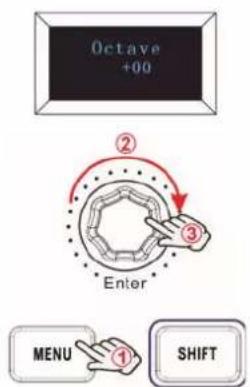
Press the ME▶U button repeatedly until the display reads "Octave" to start the function of Octave. ●his function allows the keyboard to change the Pitch up/down by octave. When this function is valid, the display shows the "Octave" and the value of current transposition. It can be adjusted via the value dial. ●he initial value is 0, adjusting scale is -4\~4. ●he operating steps and the display are shown on the left.
(1) Press the ME▶U button repeatedly until the displays reads "Octave".
(2) Rotate the value dial to adjust the keyboard octave, the display shows the current octave. Hold the "Enter" button for 2 seconds to exit the edit mode and return to parameter display mode. ●hen if you rotate the knobs, move the sliders or trigger the pads the display will show the current parameters of these controllers.
7.10 Transpose
flowchart
graph TD
    A["Transpose +000"] --> B["Enter"]
    B --> C["MENU"]
    C --> D["SHIFT"]
    style A fill:#f9f,stroke:#333
    style B fill:#ccf,stroke:#333
    style C fill:#cfc,stroke:#333
    style D fill:#fcc,stroke:#333
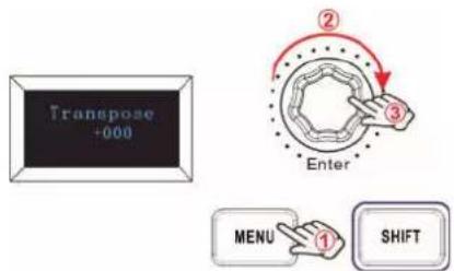
Press the ME▶U button repeatedly until the display reads “●ranspose” to start the function of ●ranspose. ●his function allows the keyboard to change the Pitch up/down by semi-tone. When this function is valid, the display shows the “●ranspose” and the value of current transpose. It can be adjusted via the value dial. ●he initial value is 0, adjusting scale is -12\~12. ●he operating steps and the display are shown on the left.
(1) Press the ME▶U button repeatedly until the display reads "●ranspose".
(2) Rotate the value dial to adjust the keyboard transpose, the display shows the current transpose. Hold the "Enter" button for 2 seconds to exit the edit mode and return to parameter display mode. ●hen if you rotate the knobs, move the sliders or trigger the pads the display will show the current parameters of these controllers.
7.11 Program change
flowchart
graph TD
    A["Program change 001"] --> B["Program change 004\nDose"]
    B --> C["Enter"]
    C --> D["MENU"]
    C --> E["SHIFT"]
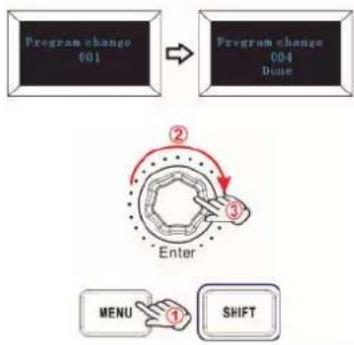
Press the ME▶U button repeatedly until the display reads "Program change" to start the function of Program change. Program change is for adjusting the voice of the current channel. When this function is valid, the display reads the "Program change" and the current voice number. It can be adjusted via the value dial and confirmed by the Enter button. ●he initial value is 1, adjusting scale is 1\~128. ●he operating steps and the display are shown on the left.
(1) Press the ME▶U button repeatedly until the displays reads "Program change".
(2) Rotate the value dial to adjust the keyboard program, the display shows the current keyboard program.
(3) Press the "Enter" button to confirm and the display shows "Done". Hold the "Enter" button for 2 seconds to exit the edit mode and return to parameter display mode. ●hen if you rotate the knobs, move the sliders or trigger the pads the display will show the current parameters of these controllers.
7.12 MIDI channel
flowchart
graph TD
    A["HIDI channel 901"] --> B["HIDI channel 004 Bone"]
    B --> C["Enter"]
    C --> D["MENU"]
    C --> E["SHIFT"]
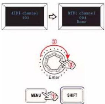
Press the ME▶U button repeatedly until the displays reads "MIDI channel" to start the function of Channel selection. Channel selection is for adjusting the current MIDI channel. When this function is valid, the display shows the "MIDI channel" and the current channel number. It can be adjusted via the value dial and confirmed by the Enter button. ●he initial value is 1, adjusting scale is 1\~16. ●he operating steps and the display are shown on the left.
(1) Press the ME▶U button repeatedly until the displays reads "MIDI channel".
(2) Rotate the value dial to adjust the keyboard MIDI channel, the display shows the current MIDI channel.
(3) Press the "Enter" button to confirm and the display shows "Done". Hold the "Enter" button for 2 seconds to exit the edit mode and return to parameter display mode. ●hen if you rotate the knobs, move the sliders or trigger the pads the display will show the current parameters of these controllers.
7.13 Select the backlit RGB color of the 8 pads
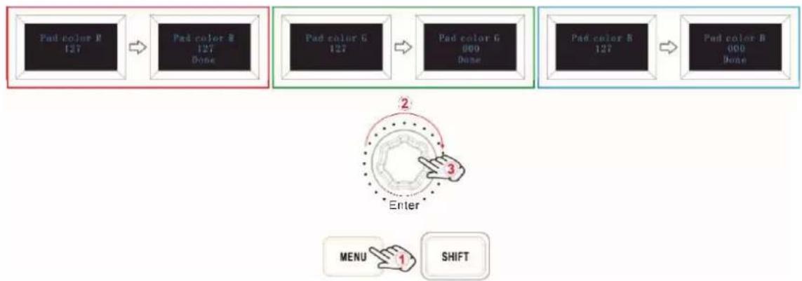
Press the ME▶U button repeatedly until the display reads "Pad color R/G/B" to start the function of selecting the backlit color of 8 the pads. When this function is valid, the display reads the "Pad color R/G/B" and the current RGB color number. R is for red, G is for green and B is for blue. It can be adjusted via the value dial and confirmed by the Enter button. ●he initial value is 127, adjusting scale is 0\~255.
For example, you may want to set Pad 1 with RED color for the backlight. ●his is done by setting the Pad color R to 127, Pad color G to 0 and Pad color B to 0 to the Pad 1. ●he operation steps are shown as below and the display reads the following:
(1) ●rigger Pad 1.
(2) Press the ME▶U button repeatedly until the display reads "Pad color R".
(3) Rotate the value dial until the display reads 127.
(4) Press the "Enter" button to confirm and the display shows "Done".
(5) Press the ME▶U button repeatedly until the display reads "Pad color G".
(6) Rotate the value dial until the display reads 0.
(7) Press the "Enter" button to confirm and the display shows "Done".
(8) Press the ME▶U button repeatedly until the display reads "Pad color B".
(9) Rotate the value dial until the display reads 0.
(10) Press the "Enter" button to confirm and the display shows "Done". Hold the "Enter" button for 2 seconds to exit the edit mode and return to parameter display mode. ●hen if you rotate the knobs, move the sliders or trigger the pads the display will show the current parameters of these controllers.
flowchart
graph LR
    A["Pad color B\n127"] --> B["Pad color B\n127\nDone"]
    B --> C["Pad color G\n127"]
    C --> D["Pad color G\n000\nDone"]
    D --> E["Pad color B\n127"]
    E --> F["Pad color B\n000\nDone"]
    F --> G["Enter"]
    G --> H["MENU 1 SHIFT"]
Reference RGB numbers for some colors:
| Color R G B | |||
| White 127 127 127 | |||
| Black | |||
| Red 127 0 0 | |||
| Green 0 127 0 | |||
| Blue 0 0 127 | |||
| Cyan 0 127 127 | |||
| Magenta | 127 0 127 | ||
| Yellow | 127 127 0 | ||
| Orange | 127 82 | 0 |
7.14 Other settings
7.14.1 Store all parameters
flowchart
graph TD
    A["Store all parameter"] --> B["Store all parameter 003 Done"]
    C["Enter"] --> D["MENU"]
    D --> E["SHIFT"]
    style A fill:#f9f,stroke:#333
    style B fill:#ccf,stroke:#333
    style C fill:#cfc,stroke:#333
    style D fill:#fcc,stroke:#333
    style E fill:#cff,stroke:#333
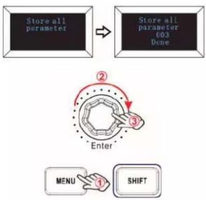
Press the ME▶U button repeatedly until the display reads "Store all parameters" to start the function of storing parameters. It stores 3 groups setup value. When this function is valid, the display reads "Store all parameter" and the current storage group number. It can be adjusted via the value dial and confirmed by the Enter button. ●he initial value is 1, adjusting scale is 1\~3. ●he operating steps and the display are shown on the left.
(1) Press the ME▶U button repeatedly until the display reads "Store all parameter".
(2) Rotate the value dial to adjust the memory area and the display shows the current memory area.
(3) Press the "Enter" button to confirm and the display shows "Done". Hold the "Enter" button for 2 seconds to exit the edit mode and return to parameter display mode. ●hen if you rotate the knobs, move the sliders or trigger the pads the display will show the current parameters of these controllers.
7.14.2 Recall all parameters
flowchart
graph TD
    A["Recall all parameter"] --> B["Recall all parameter 001 Done"]
    C["Enter"] --> D["MENU"]
    D --> E["SHIFT"]
    style A fill:#000,stroke:#fff,color:#fff
    style B fill:#000,stroke:#fff,color:#fff
    style C fill:#000,stroke:#fff,color:#fff
    style D fill:#fff,stroke:#000
    style E fill:#fff,stroke:#000
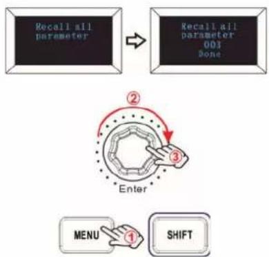
Press the ME▶U button repeatedly until the display reads "Recall all parameter" to start the function of recalling all parameters. When this function is valid, the display reads the "Recall all parameter" and the current storage group number. It can be adjusted via the value dial and confirmed by the Enter button. ●he initial value is 1, adjusting scale is 1\~3. ●he operating steps and the display are shown on the left.
(1) Press the ME▶U button repeatedly until the display reads "Recall all parameter".
(2) Rotate the value dial to select the memory area and the display shows the current memory area.
(3) Press the "Enter" button to confirm and the display shows "Done". Hold the "Enter" button for 2 seconds to exit the edit mode and return to parameter display mode. ●hen if you rotate the knobs, move the sliders or trigger the pads the display will show the current parameters of these controllers.
7.14.3 Reset
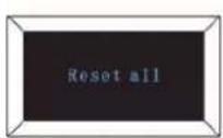
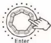
Press the ME▶U button repeatedly until the display reads "Reset all" to reset the system restoring to factory setting, sending system initial setting info at the same time. When this function is valid, the display reads "Reset all". It can be confirmed by the Enter button. ●he display is as shown on the left.
7.14.4 Sequencer remote control buttons
- here are 2 buttons used for Playback and Record control: [>>], [O]. It is common to set the 2 buttons as Sequencer remote control buttons, it needs to be working with sequencer software.
8 Use with a DAW
8.1 Using Ableton Live
With Ableton Live installed, get your controller connected to USB port on your Mac or PC using the USB cable provided and it will be automatically detected and enter Session mode. If you press the SHIF button on your controller the pads will be lighting as shown in the picture below. ●he first 2 pads of the top row are used to select pad behavior and the last pad is for selecting knob behavior.
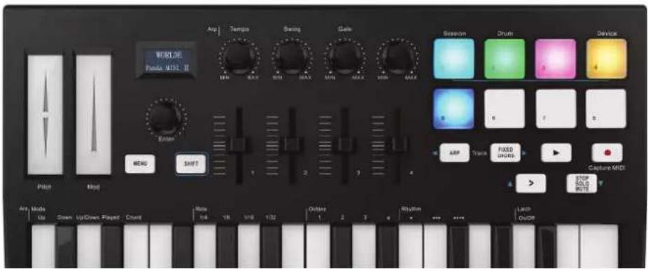
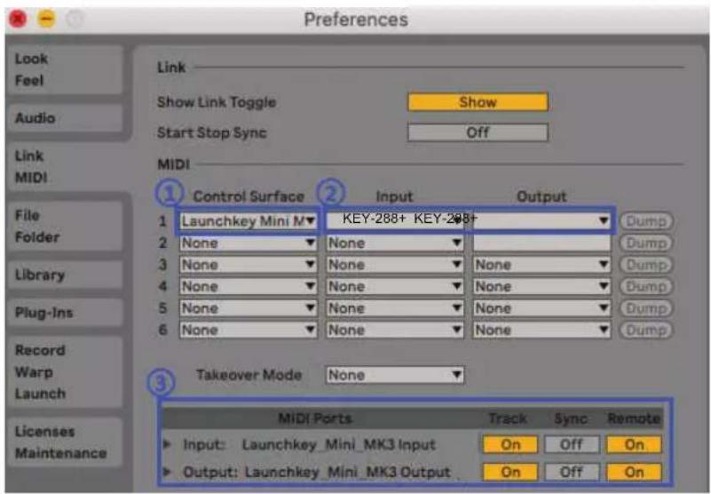
If your controller is not automatically detected in Ableton Live, you'll need to configure Live's Control Surface Preferences. ●his could be done in the 'Link/MIDI' Preferences menu in Ableton Live.
Windows: Options > Preferences > Link/MIDI
Mac: Live > Preferences > Link/MIDI
You need to make settings in the Link/MIDI tab as steps shown below.
1) First, select the Launchkey Mini MK3 from the Control Surface menu.
2) Second, select OM▶I●RO▶IC KEY-288+ (Windows) for Input and Output settings. Finally, match the ●rack, Sync and Remote settings.
8.1.1 Session Mode
Session mode is used to control Ableton Live's Session view.
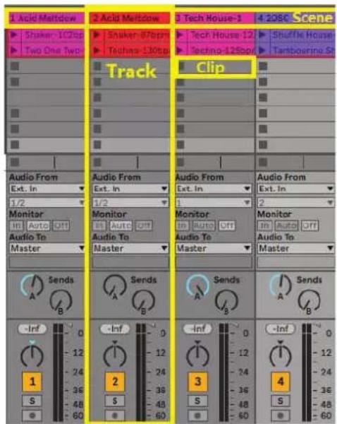
Session View is a grid that consists of clips, tracks and scenes.
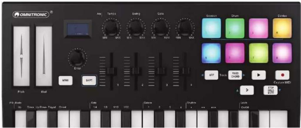
- he controller's Session mode provides an 4x2 view of the clips in your Session View. Example of the controller's pads in Session mode:
Clips are typically loops that contain MIDI notes or audio.
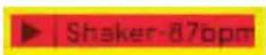
- racks represent virtual instruments or audio tracks. MIDI clips placed on instrument tracks will play back on the instrument that is assigned to that track.
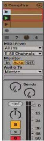
Scenes are rows of clips. Launching a scene will launch all clips in that row. •his means that you can arrange clips into horizontal

In Session mode, the pads represent the grid of clips found inside the colored rectangle in Ableton Live's Session View.
| 1 MIDI | 2 MIDI | 3 Audio | 4 Audio | Master |
| 1 | ||||
| 2 | ||||
| 3 | ||||
| 4 | ||||
| 5 | ||||
| 1-MIDI 1 | 6 | |||
| 7 | ||||
| 8 |
Any changes you make to clip position or color within Ableton Live will be represented in the Session mode of the controller. Unlit (dark) pads indicate empty clip slots.
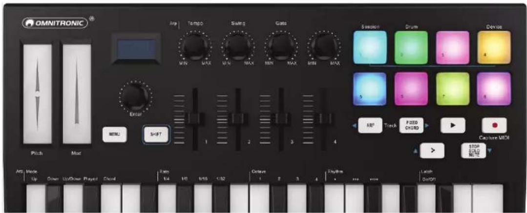
You can navigate around Session View by holding SHIF● and pressing the 4 buttons with arrows as their secondary functions: >, S●OP SOLO MU●E, ARP, and FIXED CHORD.

More specifically, you can move the currently selected grid of clips (inside Ableton Live's colored rectangle) up or down by holding SHIF• and pressing the following buttons:

SHIF● + Scene Launch (>) : ●his moves the grid of clips up one row.

SHIF● + S●OP, SOLO, MU●E: ●his moves the grid of clips down one row.

Holding SHIF● and pressing ARP (left) or FIXED CHORD (right) will select the adjacent left or right track.
- his will automatically arm the track so it is ready to receive MIDI. Release ARP or FIXED CHORD first before releasing the SHIF button.
8.1.2 Launching Clips
Pressing pads will launch clips in the corresponding location in your Session View. Pads will pulse white to indicate that a clip is playing. Pressing the pad again will relaunch the clip, and pressing an empty pad will stop playback on that track.
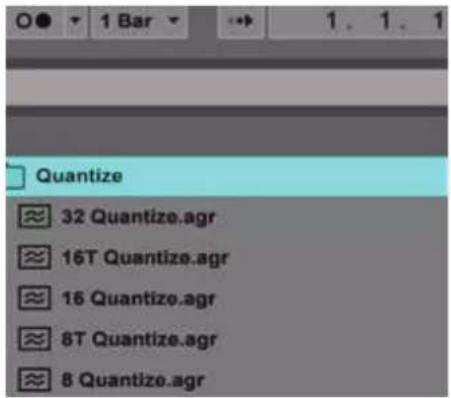
How fast clips stop or relaunch is set by Ableton Live's Global Quantisation chooser, located at the top of the Live screen. By default, this is set to 1 bar, but can go as fast as 1/32 notes, or as slow as 8 bars. It can also be set to '▶one' so clips react immediately.
8.1.3 Launching Scenes
Pressing the Scene Launch button (>) launches scenes in Ableton Live. ●his means that all of the clips in a row can start together.
8.1.4 Stop, Solo, Mute
While in Session mode, it is possible to switch the functionality of the bottom 4 pads so that they no longer launch clips. ●his is done with the S●OP, SOLO, MU●E button.
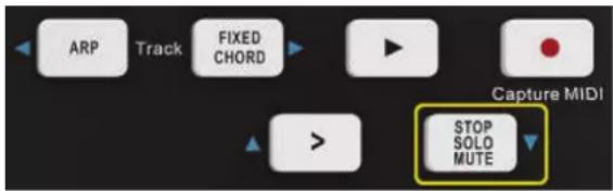
- he Stop, Solo, Mute button toggles between four different states which affect tracks in the following ways:
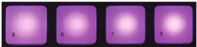
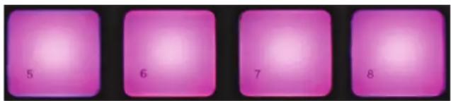
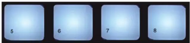
Stop (purple): In this state, pressing pads will stop any clip on the corresponding track. ●he purple pads will be in blue if tracks are not
natural_image
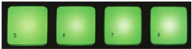
Four purple square tiles labeled 5, 6, 7, and 8 with gradient highlights (no text or symbols beyond numbers)Solo (green): In this state, pressing the pads will solo the corresponding tracks, meaning only tracks with Solo on will be heard.
Mute (pink): In this state, pressing pads will mute the corresponding tracks.
Clips (white): the fourth press (after toggling through Stop, Solo and Mute) changes the function of bottom pads back to the default.
8.1.5 Record / Capture MIDI
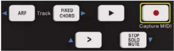
Pressing this button triggers Session Record. ●his will allow you to record what you're playing to new clips as well as overdub existing ones.

Holding SHIF● and pressing Record triggers the Capture MIDI function. ●his allows you to retrospectively capture any recently played MIDI notes in the record-armed track. ●his means that if you are not recording, but you play something that sounds great, you can use Capture MIDI to send it straight into a clip.
8.1.6 Playing and Recording Drums

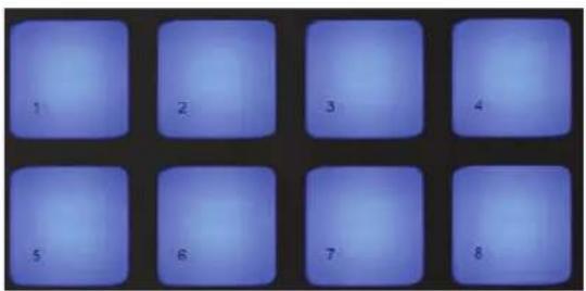
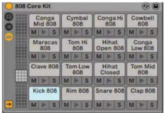
Drum mode transforms the controller's pads into velocity-sensitive drum pads. Hold SHIF• and press the Drum pad (2nd from the top left) to enter this mode. If a Drum Rack (an Ableton MIDI instrument) is loaded onto the selected Live track, and the controller is in Drum mode, the pads light up the color of the track. These pads will play whatever Drum Rack pads are visible on your computer screen.
Hold SHIF● and press either the > or S●OP, SOLO, MU●E buttons to scroll up/down a Drum Rack's bank of 128 pads. When using Ableton's Drum Racks, Drum mode will – apart from triggering sounds – select the associated Drum Rack pad within a Drum Rack. ●his means that on release, the last played Drum Rack pad becomes grey and Ableton Live shows the selected Drum Rack pad on the screen.
8.1.7 Using Ableton Live Devices
Device mode allows you to control the selected 'device' (Ableton or 3rd-party Instruments and Effects) on a Live track. Hold the SHIF button and press the Device pad (4th from top left) to use this mode.
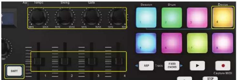
In this mode, knobs and sliders control the first 8 parameters of the selected device. ●his is especially useful for controlling Live's 8 'macro' knobs, available on Instrument and Effect Racks.
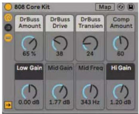
- he above picture shows an Impulse preset called 'Percussion 1'. Here, the controller knobs and sliders control sample volumes, sample start and 'stretch', as well as delay and reverb amounts.
8.1.8 Arp
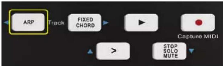
Pressing the ARP button on controller enables the Arpeggiator. After engaging Arp the controller takes your chords and creates an arpeggio – i.e. it plays each note of the chord one after another. ●he Arpeggiator will run as long as keys are held, at the rhythmic value specified by the Arp Rate.
flowchart
graph TD
    A["ARP Track"] --> B["FIXED CHORD"]
    B --> C["Play"]
    C --> D["Capture MIDI"]
    D --> E["STOP SOLO MUTE"]
    E --> F[">"]
Arpeggiator rotary knobs
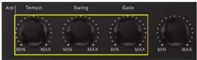
When you hold the ARP button the rotary knobs can transform your arpeggios.
| Knob Function | |
| Tempo | ●his knob speeds up or slows down your arpeggio relative to the Arp Rate. |
| Swing | ●his knob sets the amount that every other note is delayed, resulting in a swung rhythm. ●o change the Arpeggiator's Swing, press and hold the ARP button, and then turn the knob labelled Swing. By default (center position), swing will be set to 50% (meaning no swing), with extremes of 80% (very swung) and 20% (negative swing). ►egative swing means every other note is rushed, instead of delayed. |
| Gate | Adjusting this knob will create longer or shorter MIDI notes, resulting in either a more ‘staccato’ arpeggio, or a more fluid, ‘legato’ one. ●his knob goes from 1% to 200% of the space between notes. For notes that have swing applied, both notes retain the same gate length. |
Arp modes
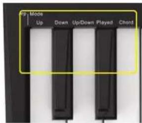
After turning on Arp you'll be in 1 of 5 Arpeggiator modes, each resulting in arpeggios of different note orders. ●o change the Arp Mode, press and hold the ARP button, and then press the key corresponding to your desired mode.
| Button Function | |
| Up | Here notes are played in ascending order (i.e. rising in pitch). If notes are added, the number of notes in the sequence will grow but remain in ascending order. For example, you may start by holding down a first note - E3 -then quickly add two more notes -C3 and G3. •he resulting arpeggio will be C3, E3 and G3. |
| Down | •his mode is similar to Up mode, but notes play in descending order (e.g. G3, E3, C3). |
| Up/Down | ●his arpeggio mode starts by playing notes in ascending order. ●hen, after reaching the highest note, the notes descend towards the lowest note, which plays once before the arpeggio rises again and stop before reaching the lowest note. ●his means that when the pattern repeats, the lowest note only plays once. |
| Played | Here notes are kept repeated in whatever order they were played. |
| Chord | All notes are played back on every rhythmic step (see Arp Rate). ●his makes playing fast chords very easy. |
Arp rates
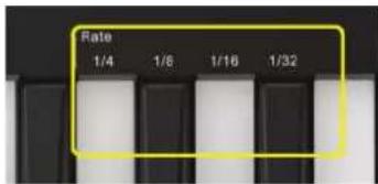
- these options specify the speed of the arpeggiated notes. Since each note is played immediately after the end of the previous one, a shorter rate (e.g. 1/32) will play an arpeggio faster than longer one (e.g. 1/4).
Rate options are common musical note values: quarter (1/4), eighth (1/8), sixteenth (1/16) and thirty-second (1/32) notes. ●o change the Arp Rate, press and hold the Arp button, and then press the key below 1/4, 1/8, 1/16, or 1/32.
Arp Octaves
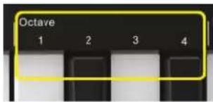
- these 4 keys specify across how many octaves your arpeggio will repeat. -o change, press and hold the Arp button, and then press the key below 1, 2, 3 or 4. Choosing an octave higher than 1 will repeat the arpeggio at higher octaves. For example, an arpeggio that was C3, E3, and G3 at 1 octave will become C3, E3, G3, C4, E4, and G4 when set to 2 octaves.
Arp Rhythms
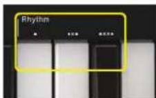
Arp Rhythms add musical rests (silent steps) to your arpeggio's pattern, allowing for greater variations in your arpeggios.
| Button Function | |
| Dots | •hese three options are rhythmic patterns. |
| O | •he normal Arpeggiator setting, this places a note on every division of the selected Arp rate. |
| OXO (note - rest - note) | •his rhythm adds a rest between every pair of notes. |
| OXXO (note - rest - rest note) | •his pattern adds two rests between every pair of notes. |
Latch
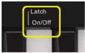
Latch lets you use the Arpeggiator without holding down keys. Any notes you press and release concurrently will form a new arpeggio pattern which the arpeggiator 'latches' onto. •he arpeggiator then continues to play as if you never released the keys. When you press a new key, the previous arpeggio erases and a new one forms.
- o turn on Latch, press and hold the Arp button, and then press the key below 'Latch'.
8.1.9 Fixed Chord
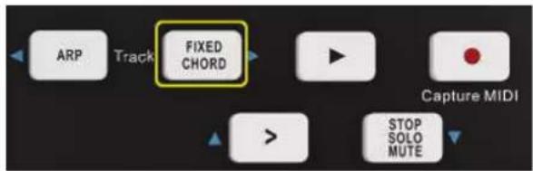
Fixed Chord lets you play a chord shape and then transpose it by pressing other keys. Press and hold the FIXED CHORD button to set a chord. ●hen, while still holding the button, press and release the keys that you wish to be part of your chord. ●he chord is now stored. Keep in mind that the first note that you input into the chord is considered the 'root note' of the chord, even if you then add notes lower than the first one, like in the example below. ●these steps illustrate how to use Fixed Chord: Press and hold the FIXED CHORD button.
- these steps illustrate how to use Fixed Chord:
1) Press and hold the FIXED CHORD button.
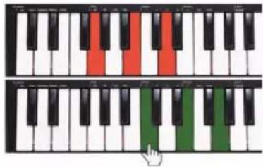
2) Press and release C, then E, and finally G (a C Major chord). •he controller stores this as the 'fixed chord'. Release the FIXED CHORD button.
3) Major chords will now sound on whatever key you press. For example, you can now press F to hear an F Major chord (shown below), or Ab to hear an Ab Major chord etc. Whenever you enter the Fixed Chord settings, the stored chord is erased and a new chord must be entered for Fixed Chord to work again.
8.2 Working with other sequencers
A MIDI sequencer will allow you to record, play back, store and edit MIDI data. Although hardware sequencers exist, we will focus on the more commonly used software sequencers in this manual. Examples of popular DAW are Cubase ^M , Logic ^M , Ableton Live ^M and so on. In order to use your controller with your sequencer, you need to set up the sequencer software so that your controller can be recognized as your DAW's MIDI input device. You need to choose a MIDI output device that is capable of making sound when MIDI data is sent to it. ●his may be a soundcard on your computer, a VS● instrument or a sound module connected to a MIDI port which is in turn connected to your computer. Please consult your sequencer's user manual for more information on how this is done. In this manual, section 8.1 "Using Ableton Live" details how your controller will appear in the device listing of your sequencer. With your controller set up to communicate with the sequencer, data will go into the sequencer and will be routed to a virtual synthesizer within the sequencer software or sent to an external sound module via a MIDI output port. ●he virtual synthesizer or external sound module will turn the MIDI data into audible sounds. You can then record the incoming MIDI data and edit your performance using your sequencer.
9 Technical Specifications
| KEY-288+ | |
| Power supply: 5 V DC 100 mA | |
| USB port: USB 2.0, type B | |
| Dimensions: Length: 19.4 cm | |
| Width: 31.8 cm | |
| Height: 4.8 cm | |
| Weight: 750 g | |
Specifications are subject to change without notice due to product improvements.
9.1 Minimum system requirements
When using your controller with a computer, the following minimum system requirements apply:
| Windows Mac | |
| i3 1.2GHz or higher (CPU requirement may be higher for laptops) | Macintosh i3*1.2GHz/P4*1.2GHz or higher (CPU requirement may be higher for laptops) |
| 1 G RAM OS X 10.3.9 with 1G RAM | |
| Direct X 9.0b or higher OS X 10.4.2 or greater with 1G RAM | |
| Windows 10 / 8 / 7/ XP / Vista *G3/G4 accelerator cards are not supported. | |
We also recommend checking the minimum system requirements of your software, as they may be higher than those listed above. USB hubs are not supported. Connect the device directly to one of your computer's built-in USB ports.
10 Appendix
10.1 Assignable controller parameter list
| CONTROLLER NO. | DEFINITION | INITIAL VALUE | VALUE RANGE |
| 0 | Bank Select MSB | 0 | 0-127 |
| 1 | Modulation MSB | 0 | 0-127 |
| 2 | Breath MSB | 127 | 0-127 |
| 3 | Controller | 0 | 0-127 |
| 4 | Foot Controller MSB | 127 | 0-127 |
| 5 | Portamento time MSB | 0 | 0-127 |
| 6 | Data Entry MSB | 2 | 0-127 |
| 7 | Channel Volume MSB | 100 | 0-127 |
| 8 | Balance MSB | 64 | 0-127 |
| 9 | Controller | 0 | 0-127 |
| 10 | Panpot MSB | 64 | 0-127 |
| 11 | Expression MSB | 127 | 0-127 |
| 12 | Effect Control 1 MSB | 0 | 0-127 |
| 13 | Effect Control 2 MSB | 0 | 0-127 |
| 14-31 | Controller | 0 | 0-127 |
| 32 | Bank Select LSB | 0 | 0-127 |
| 33 | Modulation LSB | 0 | 0-127 |
| 34 | Breath LSB | 127 | 0-127 |
| 35 | Controller | 0 | 0-127 |
| 36 | Foot Controller LSB | 127 | 0-127 |
| 37 | Portamento time LSB | 0 | 0-127 |
| 38 | Data Entry LSB | 0 | 0-127 |
| 39 | Channel Volume LSB | 127 | 0-127 |
| 40 | Balance LSB | 64 | 0-127 |
| 41 | Controller | 0 | 0-127 |
| 42 | Panpot LSB | 64 | 0-127 |
| 43 | Expression LSB | 127 | 0-127 |
| 44-63 | Controller | 0 | 0-127 |
| 64 | Sustain | 0 | 0-127 |
| 65 | Portamento | 0 | 0-127 |
| 66 | Sostenuto | 0 | 0-127 |
| 67 | Soft Pedal | 0 | 0-127 |
| 68 | Legato FootSwitch | 0 | 0-127 |
| 69 | Hold 2 | 0 | 0-127 |
| 70 | Sound Controller | 64 | 0-127 |
| 71 | Resonance | 64 | 0-127 |
| 72 | Release Time | 64 | 0-127 |
| 73 | Attack Time | 64 | 0-127 |
| 74 | Cutoff | 64 | 0-127 |
| 75 | Decay Time | 0 | 0-127 |
| 76 | Vibrato Depth | 64 | 0-127 |
| 77 | Vibrato Depth | 64 | 0-127 |
| 78 | Vibrato Depth | 64 | 0-127 |
| 79 | Sound Controller | 64 | 0-127 |
| 80-83 | Controller | 0 | 0-127 |
| 84 | Portamento Control | 0 | 0-127 |
| 85-90 | Controller | 0 | 0-127 |
| 91 | Reverb | 40 | 0-127 |
| 92 | Effects | 0 | 0-127 |
| 93 | Chorus | 0 | 0-127 |
| 94 | Effects | 0 | 0-127 |
| 95 | Effects | 0 | 0-127 |
| 96 | RPN Increment | 0 | 0-127 |
| 97 | RPN Decrement | 0 | 0-127 |
| 98 | NRPN LSB | 0 | 0-127 |
| 99 | NRPN MSB | 0 | 0-127 |
| 100 | RPN LSB | 0 | 0-127 |
| 101 | RPN MSB | 0 | 0-127 |
| 102-119 | Controller | 0 | 0-127 |
| 120 | All Sound Off | 0 | 0-127 |
| 121 | Reset All Controllers | 0 | 0-127 |
| 122 | Local Control | 0 | 0-127 |
| 123 | All Notes Off | 0 | 0-127 |
| 124 | OMNI Off | 0 | 0-127 |
| 125 | OMNI On | 0 | 0-127 |
| 126 | Mono | 0 | 0-127 |
| 127 | Poly | 0 | 0-127 |
| 128 | Pitch Bend Sensitivity (RPN) | 2 | 0-127 |
| 129 | Channel Fine Tuning (RPN) | 64 | 0-127 |
| 130 | Channel Coarse Tuning (RPN) | 64 | 0-127 |
| 131 | Modulation Depth Range (RPN) | 64 | 0-127 |
| 132 | Vibrato Rate (NRPN) | 64 | 0-127 |
| 133 | Vibrato Depth (NRPN) | 64 | 0-127 |
| 134 | Vibrato Delay (NRPN) | 64 | 0-127 |
| 135 | Filter Cutoff Frequency (NRPN) | 64 | 0-127 |
| 136 | Filter Resonance (NRPN) | 64 | 0-127 |
| 137 | EQ Low Gain (NRPN) | 64 | 0-127 |
| 138 | EQ High Gain (NRPN) | 64 | 0-127 |
| 139 | EQ Low Frequency (NRPN) | 64 | 0-127 |
| 140 | EQ High Frequency (NRPN) | 64 | 0-127 |
| 141 | EG Attack Time (NRPN) | 64 | 0-127 |
| 142 | EG Decay Time (NRPN) | 64 | 0-127 |
| 143 | EG Release Time (NRPN) | 64 | 0-127 |
| 144 | Polyphonic key pressure | 100 | 0-127 |
| 145 | After touch | 100 | 0-127 |
| 146 | Pitch Bend | 64 | 0-127 |
| 147 | Master Volume | 100 | 0-127 |
| 148 | Start (MTC) | - | - |
| 149 | Continue (MTC) | - | - |
| 150 | Stop (MTC) | - | - |
| 151 | Reset (MTC) | - | - |
| 152 | Program | 0 | 0-127 |
| 153 | Global Channel | 0 | 0-15 |
| 154 | Octave | 0 | -3~3 |
| 155 | Transpose | 0 | -12~12 |
| 156 | Tempo | 100 | 20-250 |
| 157 | Keyboard Curve | 0 | 0-4 |
| 158 | Pedal A Curve | 64 | 1-127 |
10.2 C-note value and the corresponding numerical number
| Note | NO. | Note | NO. | Note | NO. | Note | NO. | Note | NO. | Note | NO. | Note | NO. | Note | NO. |
| C-1 | 0 | F0 | 17 | Bb 1 | 34 | Eb 3 | 51 | G#4 | 68 | C#6 | 85 | F#7 | 102 | B8 | 119 |
| C#-1 | 1 | F#0 | 18 | B1 | 35 | E3 | 52 | A4 | 69 | D6 | 86 | G7 | 103 | C9 | 120 |
| D-1 | 2 | G0 | 19 | C2 | 36 | F3 | 53 | Bb 4 | 70 | Eb 6 | 87 | G#7 | 104 | C#9 | 121 |
| Eb-1 | 3 | G#0 | 20 | C#2 | 37 | F#3 | 54 | B4 | 71 | Eb 6 | 88 | A7 | 105 | D9 | 122 |
| E-1 | 4 | A0 | 21 | D2 | 38 | G3 | 55 | C5 | 72 | F6 | 89 | Bb 7 | 106 | Eb 9 | 123 |
| F-1 | 5 | Bb 0 | 22 | Eb 2 | 39 | G#3 | 56 | C#5 | 73 | F#6 | 90 | B7 | 107 | E9 | 124 |
| F#-1 | 6 | B0 | 23 | E2 | 40 | A3 | 57 | D5 | 74 | G6 | 91 | C8 | 108 | F9 | 125 |
| G-1 | 7 | C1 | 24 | F2 | 41 | Bb 3 | 58 | Eb 5 | 75 | G#6 | 92 | C#8 | 109 | F#9 | 126 |
| G#-1 | 8 | C#1 | 25 | F#2 | 42 | B3 | 59 | E5 | 76 | A6 | 93 | D8 | 110 | G9 | 127 |
| A-1 | 9 | D1 | 26 | G2 | 43 | C4 | 60 | F5 | 77 | Bb 6 | 94 | Eb 8 | 111 | ||
| Bb-1 | 10 | Eb 1 | 27 | G#2 | 44 | C#4 | 61 | F#5 | 78 | B6 | 95 | E8 | 112 | ||
| B-1 | 11 | E1 | 28 | A2 | 45 | D4 | 62 | G5 | 79 | C7 | 96 | F8 | 113 | ||
| C0 | 12 | F1 | 29 | Bb 2 | 46 | Eb 4 | 63 | G#5 | 80 | C#7 | 97 | F#8 | 114 | ||
| C#0 | 13 | F#1 | 30 | B2 | 47 | E4 | 64 | A5 | 81 | D7 | 98 | G8 | 115 | ||
| D0 | 14 | G1 | 31 | C3 | 48 | F4 | 65 | Bb 5 | 82 | Eb 7 | 99 | G#8 | 116 | ||
| Eb 0 | 15 | G#1 | 32 | C#3 | 49 | F#4 | 66 | B5 | 83 | E7 | 100 | A8 | 117 | ||
| E0 | 16 | A1 | 33 | D3 | 50 | G4 | 67 | C6 | 84 | F7 | 101 | Bb 8 | 118 |
10.3 General MIDI drums-note assignments
| MIDI Note | Drum Sound | MIDI Note | Drum Sound | MIDI Note | Drum Sound |
| 35 | Acoustic Bass Drum | 52 | Chinese Cymbal | 69 | Cabasa |
| 36 | Bass Drum 1 | 53 | Ride Bell | 70 | Maracas |
| 37 | Side Stick | 54 | Tambourine | 71 | Short Whistle |
| 38 | Acoustic Snare | 55 | Splash Cymbal | 72 | Long Whistle |
| 39 | Hand Clap | 56 | Cowbell | 73 | Short Guiro |
| 40 | Electric Snare | 57 | Crash Cymbal 2 | 74 | Long Guiro |
| 41 | Low Floor Tom | 58 | Vibraslap | 75 | Claves |
| 42 | Closed Hi-Hat | 59 | Ride Cymbal 2 | 76 | Hi Wood Block |
| 43 | High Floor Tom | 60 | Hi Bongo | 77 | LowWood Block |
| 44 | Pedal Hi-Hat | 61 | Low Bongo | 78 | Mute Cuica |
| 45 | Low Tom | 62 | Mute Hi Conga | 79 | Open Cuica |
| 46 | Open Hi-Hat | 63 | Open Hi Conga | 80 | Mute Triangle |
| 47 | Low-Mid Tom | 64 | Low Conga | 81 | Open Triangle |
| 48 | Hi-Mid Tom | 65 | High Timbale | ||
| 49 | Crash Cymbal 1 | 66 | Low Timbale | ||
| 50 | High Tom | 67 | High Agogo | ||
| 51 | Ride Cymbal 1 | 68 | Low Agogo |
10.5 General MIDI Instruments-Program Change Numbers
| Piano | Bass | Reed | Synth Effects |
| 0 Acoustic Grand Piano | 32 Acoustic Bass | 64 Soprano Sax | 96 SFX Rain |
| 1 Bright Acoustic Piano | 33 Fingered Bass | 65 Alto Sax | 97 SFX Soundtrack |
| 2 Electric grand Piano | 34 Electric Picked Bass | 66 Tenor Sax | 98 SFX Crystal |
| 3 Honky Tonk Piano | 35 Fretless Bass | 67 Baritone Sax | 99 SFX Atmosphere |
| 4 Electric Piano 1 | 36 Slap Bass 1 | 68 Oboe | 100 SFX Brightness |
| 5 Electric Piano 2 | 37 Slap Bass 2 | 69 English Horn | 101 SFX Goblins |
| 6 Harpsichord | 38 Syn Bass 1 | 70 Bassoon | 102 SFX Echoes |
| 7 Clavinet | 39 Syn Bass 2 | 71 Clarinet | 103 SFX Sci-Fi |
| Chromatic Percussion | Strings/Orchestra | Pipe | Ethnic |
| 8 Celesta | 40 Violin | 72 Piccolo | 104 Sitar |
| 9 Glockenspiel | 41 Viola | 73 Flute | 105 Banjo |
| 10 Music Box | 42 Cello | 74 Recorder | 106 Shamisen |
| 11 Vibraphone | 43 Contrabass | 75 Pan Flute | 107 Koto |
| 12 Marimba | 44 Tremolo Strings | 76 Bottle Blow | 108 Kalimba |
| 13 Xylophone | 45 Pizzicato Strings | 77 Shakuhachi | 109 Bag Pipe |
| 14 Tubular bells | 46 Orchestral Harp | 78 Whistle | 110 Fiddle |
| 15 Dulcimer | 47 Timpani | 79 Ocarina | 111 Shanai |
| Organ | Ensemble | Synth Lead | Percussive |
| 16 Drawbar Organ | 48 String Ensemble 1 | 80 Syn Square Wave | 112 Tinkle Bell |
| 17 Percussive Organ | 49 String Ensemble 2 | 81 Syn Sawtooth Wave | 113 Agogo |
| 18 Rock Organ | 50 Syn Strings 1 | 82 Syn Calliope | 114 Steel Drums |
| 19 Church Organ | 51 Syn Strings 2 | 83 Syn Chiff | 115 Woodblock |
| 20 Reed Organ | 52 Choir Aahs | 84 Syn Charang | 116 Taiko Drum |
| 21 Accordion | 53 Voice Oohs | 85 Syn Voice | 117 Melodic Tom |
| 22 Harmonica | 54 Syn Choir | 86 Syn Sawtooth Wave | 118 Syn Drum |
| 23 Tango Accordion | 55 Orchestral Hit | 87 Syn Brass & Lead | 119 Reverse Cymbal |
| Guitar | Brass | Synth Pad | Sound Effects |
| 24 Nylon Acoustic | 56 Trumpet | 88 New Age Syn Pad | 120 Guitar Fret Noise |
| 25 Steel Acoustic | 57 Trombone | 89 Warm Syn Pad | 121 Breath Noise |
| 26 Jazz Electric | 58 Tuba | 90 Polysynth Syn Pad | 122 Seashore |
| 27 Clean Electric | 59 Muted Trumpet | 91 Choir Syn Pad | 123 Bird Tweet |
| 28 Muted Electric | 60 French Horn | 92 Bowed Syn Pad | 124 Telephone Ring |
| 29 Overdrive | 61 Brass Section | 93 Metal Syn Pad | 125 Helicopter |
| 30 Distorted | 61 Syn Brass 1 | 94 Halo Syn Pad | 126 Applause |
| 31 Harmonics | 62 Syn Brass 2 | 95 Sweep Syn Pad | 127 Gun Shot |
- KEY-288+
- Inhalt
- Mobile Geräte
- Android-Geräte
- Session-Modus
- Stop, Solo, Mute
- www.omnitronic.de
- Introduction
- Product features
- Package contents
- Safety Instructions
- Protecting the Environment
- Disposal of old equipment
- Making the Connections
- Computer
- Mobile devices
- Android devices
- Use as a stand-alone MIDI Controller
- Parts and Their Functions
- Basic MIDI Control
- MIDI control messages
- Programming controls
- Control assignment
- Assignable Knobs
- Assignable sliders
- Pad Note setting
- Keyboard Velocity curve
- Keyboard Velocity Curves:
- Pad velocity
- Transpose
- Program change
- MIDI channel
- Select the backlit RGB color of the 8 pads
- Other settings
- Store all parameters
- Recall all parameters
- Reset
- Sequencer remote control buttons
- Use with a DAW
- Using Ableton Live
- Session Mode
- Launching Clips
- Launching Scenes
- Record / Capture MIDI
- Playing and Recording Drums
- Using Ableton Live Devices
- Arp
- Arp rates
- Arp Octaves
- Arp Rhythms
- Latch
- Fixed Chord
- Working with other sequencers
- Technical Specifications
- Minimum system requirements
- Appendix
- Assignable controller parameter list
Brand : Omnitronic
Model : KEY-288+
Category : DJ Equipment