
HPP-30CH90AERI R32-1 - Heat pump Vivax - Free user manual and instructions
Find the device manual for free HPP-30CH90AERI R32-1 Vivax in PDF.

| Product Type | Air-to-Air Heat Pump (Split System) |
| Brand | Vivax |
| Model | HPP-30CH90AERI R32-1 |
| Refrigerant | R32 |
| Cooling Capacity | 9.0 kW (30,800 BTU/h) |
| Heating Capacity | 10.0 kW (34,100 BTU/h) |
| Power Supply | 230 V ~ 50 Hz, 1 Phase |
| Indoor Unit Dimensions (W x H x D) | 1000 x 320 x 230 mm |
| Outdoor Unit Dimensions (W x H x D) | 900 x 700 x 350 mm |
| Indoor Unit Weight | 15 kg |
| Outdoor Unit Weight | 55 kg |
| Energy Efficiency Ratio (EER) | 3.5 (Cooling) |
| Coefficient of Performance (COP) | 4.0 (Heating) |
| Noise Level (Indoor / Outdoor) | 45 dB(A) / 55 dB(A) |
| Main Functions | Cooling, Heating, Dehumidification, Fan, Auto Mode, Timer, Sleep Mode, Swing |
| Filter Type | Washable Anti-Bacterial Filter |
| Maintenance & Cleaning | Clean filters every 2-4 weeks; wipe unit with damp cloth; never use water directly |
| Safety Features | Overload Protection, Auto Restart, Child Lock (optional), Grounding |
| Spare Parts & Repairability | Available through authorized service centers; main parts: fan motor, compressor, PCB, sensors |
| General Information | R32 refrigerant; 7-year warranty on compressor; 2-year on parts |
Frequently Asked Questions - HPP-30CH90AERI R32-1 Vivax
User questions about HPP-30CH90AERI R32-1 Vivax
0 question about this device. Answer the ones you know or ask your own.
Ask a new question about this device
Download the instructions for your Heat pump in PDF format for free! Find your manual HPP-30CH90AERI R32-1 - Vivax and take your electronic device back in hand. On this page are published all the documents necessary for the use of your device. HPP-30CH90AERI R32-1 by Vivax.
USER MANUAL HPP-30CH90AERI R32-1 Vivax
HPP-24CH70AERI R32-1
HPP-30CH90AERI R32-1
HPP-41CH120AERI R32-1
EN
User manual
INSTALLATION AND OWNER'S MANUAL
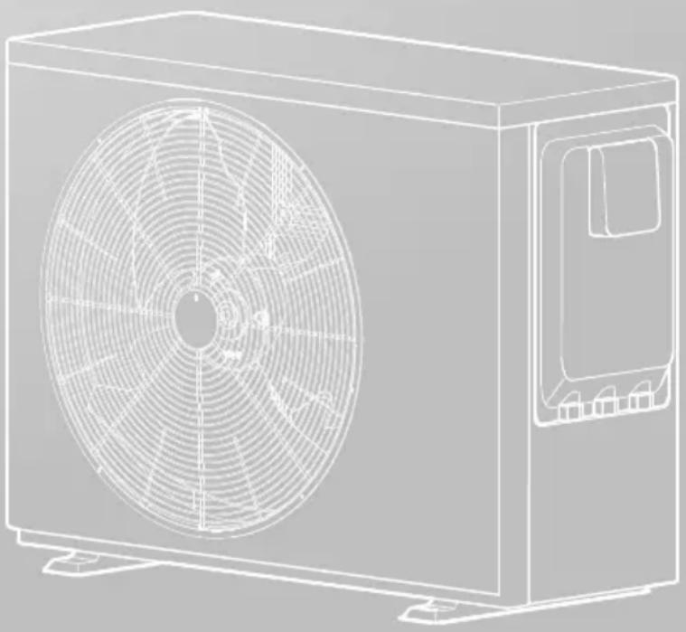
Swimming pool heat pump
natural_image
Line drawing of a rectangular air conditioner unit with fan blades and mounting base (no text or symbols)IMPORTANT NOTE:
Thank you very much for purchasing our product.
Before using your unit, please read this manual carefully and keep it for future reference.
RECOGNIZE THIS SYMBOL AS AN INDICATION OF IMPORTANT SAFETY INFORMATION
WARNING
These instructions are intended as an aid to qualified licensed service personnel for proper installation, adjustment and operation of this unit. Read these instructions thoroughly before attempting installation or operation. Failure to follow these instructions may result in improper installation, adjustment, service or maintenance possibly resulting in fire, electrical shock, property damage, personal injury or death.
CAUTION
Please drain water when the unit is not in use in winter to avoid freeze damage.
CONTENTS
1 SAFETY PRECAUTIONS 02
2 GENERAL INTRODUCTION 05
3 ACCESSORIES SUPPLIED WITH THE UNIT 05
4 INSTALLATION SITE
• 4.1 Location Space Requirement 06
• 4.2 Location Selection In Cold Climates 07
• 4.3 Location Selection In Direct Sunlight 07
5 INSTALLATION PRECAUTIONS
- 5.1 Dimensions 08
- 5.2 Shock Absorption and Fixations ...... 08
- 5.3 Drain Hole Position 09
• 5.4 Inlet & Outlet Water Pipes 10
5.5 Field Wiring 10
• 5.6 Safety Device Requirement ...... 11
6 TYPICAL APPLICATIONS 12
7 OVERVIEW OF THE UNIT
• 7.1 Refrigerant Cycle 12
• 7.2 Main Components 13
• 7.3 Inverter Drive Board 14
•7.4 Main Control Board 15
- 7.5 Connection Of Optional Function 16
8 START-UP AND CONFIGURATION
• 8.1 Initial Start-up At Low Outdoor Ambient Temperature 17
• 8.2 Pre-operation Checks 17
• 8.3 Failure Diagnosis At First Installation 17
9 FINAL CHECKS AND TEST RUN 18
10 MAINTENANCE AND SERVICE
• 10.1 Routine Maintenance 18
• 10.2 Notes For Maintenance & Repair 19
11 TROUBLESHOOTING 21
12 TECHNICAL SPECIFICATIONS 23
13 INFORMATION SERVICING 24
natural_image
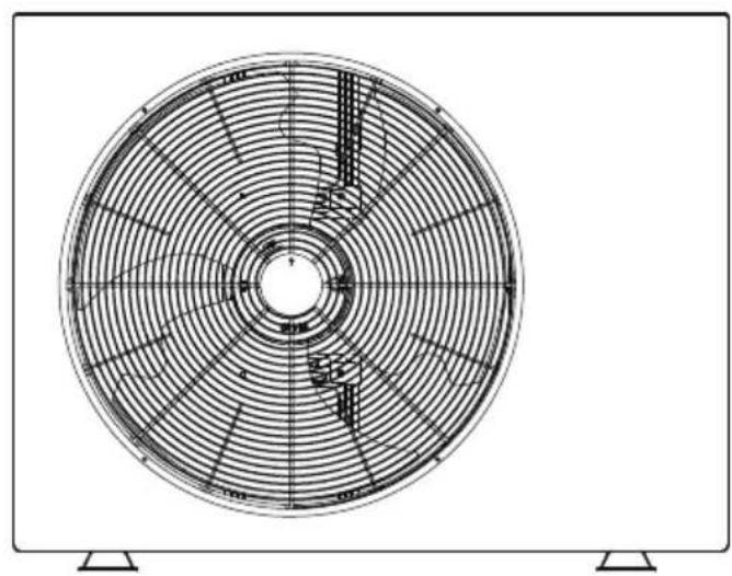
Top-down schematic of a circular fan or fan with radial blades and central hub (no text or symbols)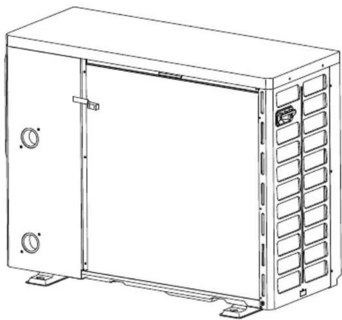
natural_image
Line drawing of a rectangular industrial enclosure with doors and ventilation grilles (no text or symbols)NOTE
- The pictures in this manual are for reference only, please refer to the actual product.
1 SAFETY PRECAUTIONS
The precautions listed here are divided into the following types. They are quite important, so be sure to follow them carefully. Meanings of DANGER, WARNING, CAUTION and NOTE symbols.
i INFORMATION
- Read these instructions carefully before installation. Keep this manual in a handy for future reference.
- Improper installation of equipment or accessories may result in electric shock, short-circuit, leakage, fire or other damage to the equipment. Be sure to only use accessories made by the supplier, which are specifically designed for the equipment and make sure to get installation done by a professional.
- All the activities described in this manual must be carried out by a licensed technician. Be sure to wear adequate personal protection equipment such as gloves and safety glasses while installing the unit or carrying out maintenance activities.
• Contact your dealer for any further assistance.
natural_image
Warning symbol of a flame inside a triangle (no text or numbers)Caution: Risk of fire/ flammable materials
WARNING
Servicing shall only be performed as recommended by the equipment manufacturer. Maintenance and repair requiring the assistance of other skilled personnel shall be carried out under the supervision of the person competent in the use of flammable refrigerants.
DANGER
Indicates an imminently hazardous situation which if not avoided, will result in death or serious injury.
WARNING
Indicates a potentially hazardous situation which if not avoided, could result in death or serious injury.
CAUTION
Indicates a potentially hazardous situation which if not avoided, may result in minor or moderate injury. It is also used to alert against unsafe practices.
NOTE
Indicates situations that could only result in accidental equipment or property damage.
Explanation of symbols displayed on the unit
 | WARNING | This symbol shows that this appliance used a flammable refrigerant. If the refrigerant is leaked and exposed to an external ignition source, there is a risk of fire. |
 | CAUTION | This symbol shows that the operation manual should be read carefully. |
 | CAUTION | This symbol shows that a service personnel should be handling this equipment with reference to the installation manual. |
 | CAUTION | This symbol shows that information is available such as the operating manual or installation manual. |
DANGER
• Before touching electric terminal parts, turn off power switch.
- When service panels are removed, live parts can be easily touched by accident.
- Never leave the unit unattended during installation or servicing when the service panel is removed.
- Do not touch water pipes during and immediately after operation as the pipes may be hot and could burn your hands. To avoid injury, give the piping time to return to normal temperature or be sure to wear protective gloves.
- Do not touch any switch with wet fingers. Touching a switch with wet fingers can cause electrical shock.
• Before touching electrical parts, turn off all applicable power to the unit.
WARNING
- Tear apart and throw away plastic packaging bags so that children will not play with them. Children playing with plastic bags face danger of death by suffocation.
• Safely dispose of packing materials such as nails and other metal or wood parts that could cause injuries. - Ask your dealer or qualified personnel to perform installation work in accordance with this manual. Do not install the unit yourself. Improper installation could result in water leakage, electric shocks or fire.
- Be sure to use only specified accessories and parts for installation work. Failure to use specified parts may result in water leakage, electric shocks, fire, or the unit falling from its mount.
- Install the unit on a foundation that can withstand its weight. Insufficient physical strength may cause the equipment to fall and possible injury.
- Perform specified installation work with full consideration of strong wind, hurricanes, or earthquakes. Improper installation work may result in accidents due to equipment falling.
- Make certain that all electrical work is carried out by qualified personnel according to the local laws and regulations and this manual using a separate circuit. Insufficient capacity of the power supply circuit or improper electrical construction may lead to electric shocks or fire.
- Be sure to install a ground fault circuit interrupter according to local laws and regulations. Failure to install a ground fault circuit interrupter may cause electric shocks and fire.
- Make sure all wiring is secure. Use the specified wires and ensure that terminal connections or wires are protected from water and other adverse external forces. Incomplete connection or affixing may cause a fire.
- When wiring the power supply, form the wires so that the front panel can be securely fastened. If the front panel is not in place there could be overheating of the terminals, electric shocks or fire.
• After completing the installation work, check to make sure that there is no refrigerant leakage. - Never directly touch any leaking refrigerant as it could cause severe frostbite. Do not touch the refrigerant pipes, during and immediately after operation as the refrigerant pipes may be hot or cold, depending on the condition of the refrigerant flowing through the refrigerant piping, compressor and other refrigerant cycle parts. Burns or frostbite are possible if you touch the refrigerant pipes. To avoid injury, give the pipes time to return to normal temperature or, if you must touch them, be sure to wear protective gloves.
- Do not touch the internal parts (pump, backup heater, etc.) during and immediately after operation. Touching the internal parts can cause burns. To avoid injury, give the internal parts time to return to normal temperature or, if you must touch them, be sure to wear protective gloves.
CAUTION
• Ground the unit.
• Grounding resistance should be according to local laws and regulations.
- Do not connect the ground wire to gas or water pipes, lightning conductors or telephone ground wires.
• Incomplete grounding may cause electric shocks.
- Gas pipes: Fire or an explosion might occur if the gas leaks.
- Water pipes: Hard vinyl tubes are not effective grounds.
- Lightning conductors or telephone ground wires: Electrical threshold may rise abnormally if struck by a lightning bolt.
- Install the power wire at least 3 feet (1 meter) away from televisions or radios to prevent interference or noise. (Depending on the radio waves, a distance of 3 feet (1 meter) may not be sufficient to eliminate the noise.)
- Do not wash the unit. This may cause electric shocks or fire. The appliance must be installed in accordance with national wiring regulations. If the supply cord is damaged, it must be replaced by the manufacturer, its service agent or similarly qualified persons in order to avoid a hazard.
- Do not install the unit in the following places:
- Where there is mist of mineral oil, oil spray or vapors. Plastic parts may deteriorate, and cause them to come loose or water to leak.
- Where corrosive gases (such as sulphurous acid gas) are produced. Where corrosion of copper pipes or soldered parts may cause refrigerant to leak.
- Where there is machinery which emits electromagnetic waves. Electromagnetic waves can disturb the control system and cause equipment malfunction.
- Where flammable gases may leak, where carbon fiber or ignitable dust is suspended in the air or where volatile flammables such as paint thinner or gasoline are handled. These types of gases might cause a fire.
- Where the air contains high levels of salt such as near the ocean.
- Where voltage fluctuates a lot, such as in factories.
- In vehicles or vessels.
- Where acidic or alkaline vapors are present.
- This appliance can be used by children 8 years old and above and persons with reduced physical, sensory or mental capabilities or lack of experience and knowledge if they are supervised or given instruction on using the unit in a safe manner and understand the hazards involved. Children should not play with the unit. Cleaning and user maintenance should not be done by children without supervision.
• Children should be supervised to ensure that they do not play with the appliance. - If the supply cord is damaged, it must be replaced by the manufacturer or its service agent or a similarly qualified person.
- DISPOSAL: Do not dispose this product as unsorted municipal waste. Collection of such waste separately for special treatment is necessary. Do not dispose of electrical appliances as municipal waste, use separate collection facilities. Contact your local government for information regarding the collection systems available. If electrical appliances are disposed of in landfills or dumps, hazardous substance can leak into the groundwater and get into the food chain, damaging your health and well-being.
- The wiring must be performed by professional technicians in accordance with national wiring regulation and this circuit diagram. An all-pole disconnection device which has at least 3mm separation distance in all pole and a residual current device(RCD) with the rating not exceeding 30mA shall be incorporated in the fixed wiring according to the national rule.
- Confirm the safety of the installation area (walls, floors, etc.) without hidden dangers such as water, electricity, and gas. Before wiring/pipes.
- Before installation, check whether the user's power supply meets the electrical installation requirements of unit (including reliable grounding, leakage, and wire diameter electrical load, etc.). If the electrical installation requirements of the product are not met, the installation of the product is prohibited until the product is rectified.
- When installing multiple air conditioners in a centralized manner, please confirm the load balance of the three-phase power supply, and multiple units are prevented from being assembled into the same phase of the three-phase power supply.
• Product installation should be fixed firmly. Take reinforcement measures, when necessary.
NOTE
• About Fluorinated Gasses
- This heat pump unit contains fluorinated gasses. For specific information on the type of gas and the amount, please refer to the relevant label on the unit itself. Compliance with national gas regulations shall be observed.
- Installation, service, maintenance and repair of this unit must be performed by a certified technician.
- Product uninstallation and recycling must be performed by a certified technician.
- If the system has a leak-detection system installed, it must be checked for leaks at least every 12 months. When the unit is checked for leaks, proper record-keeping of all checks is strongly recommended.
2 GENERAL INTRODUCTION
- These units are used for both heating and cooling the water of swimming pool, they can keep the pool water temperature stable at the set temperature to provide comfortable swimming condition in different seasons.
- A wired controller is supplied with the unit.
NOTE
• Maximum length of communication wirings between the unit and the controller is 20m.
- Power cords and communication wires must be laid out separately, they can not be placed in the same conduit. Otherwise, it may lead to electromagnetic interference. Power cords and communication wires should not come in contact with the refrigerant pipe so as to prevent the high temperature pipe from damaging wires.
• Communication wires must use shielded lines.
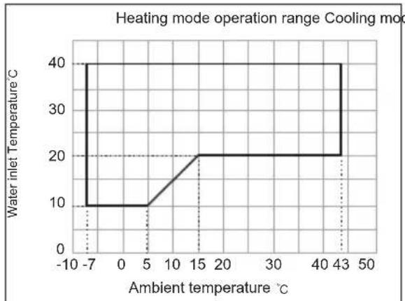
Operation range
line
| Ambient temperature °C | Water inlet Temperature °C | | ---------------------- | -------------------------- | | -7 | 40 | | 0 | 10 | | 5 | 10 | | 15 | 20 | | 43 | 40 |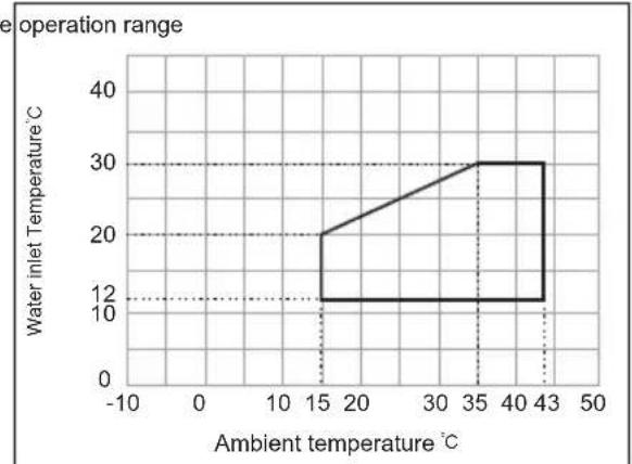
line
| Ambient temperature °C | Water inlet Temperature °C | | ---------------------- | -------------------------- | | 15 | 20 | | 43 | 30 |3 ACCESSORIES SUPPLIED WITH THE UNIT
| ShapeName | Quantity | |
| Installation & owner's manual(this book) | [0CH8] | 1 |
| Installation & owner's manualWired controller |  | 1 |
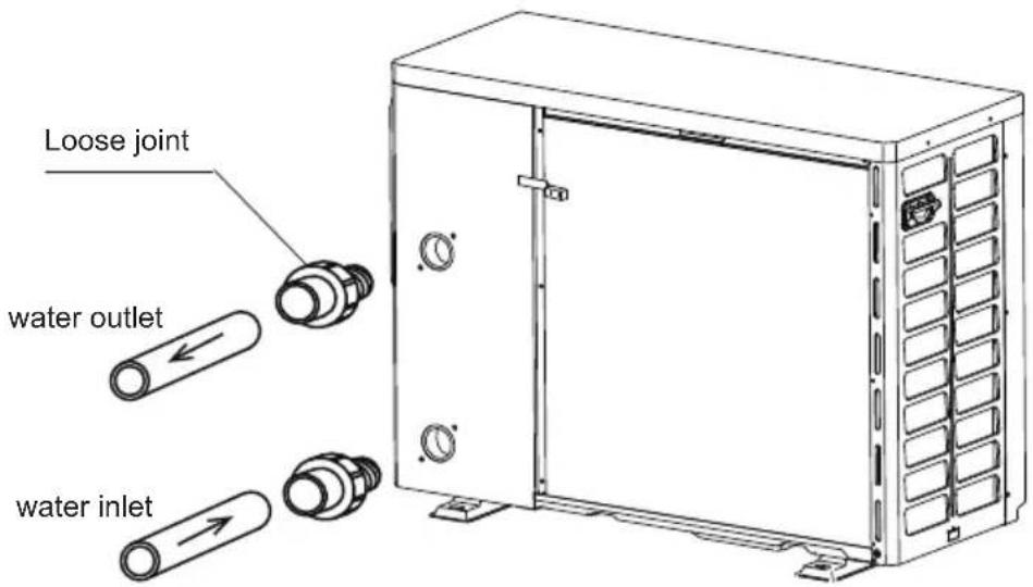
| Loose joint |  | 2 |
| Drain connection |  | 1 |
| Wired controller |  | 1 |
4 INSTALLATION SITE
WARNING
- There is flammable refrigerant in the unit and it should be installed in a well-ventilated site. If the unit is installed inside, an additional refrigerant detection device and ventilation equipment must be added in accordance with the standard EN378. Be sure to adopt adequate measures to prevent the unit from being used as a shelter by small animals.
- Small animals making contact with electrical parts can cause malfunction, smoke or fire. Please instruct the customer to keep the area around the unit clean.
- Select an installation site where the following conditions are satisfied and one that meets with your customer's approval.
- Places that are well-ventilated.
- Places where the unit does not disturb neighbors.
- Safe places which can bear the unit's weight and vibration and where the unit can be installed at an even level.
- Places where there is no possibility of flammable gas or product leak.
The equipment is not intended for use in a potentially explosive atmosphere. - Places where servicing space can be well ensured.
- Places where the units' piping and wiring lengths come within the allowable ranges.
- Places where water leaking from the unit cannot cause damage to the location (e.g. in case of a blocked drain pipe).
- Places where rain can be avoided as much as possible.
Do not install the unit in places often used as a work space. In case of construction work (e.g. grinding etc.) where a lot of dust is created, the unit must be covered.
Do not place any object or equipment on top of the unit (top plate).
Do not climb, sit or stand on top of the unit. - Be sure that sufficient precautions are taken in case of refrigerant leakage according to relevant local laws and regulations.
- Don't install the unit near the sea or where there is corrosion gas.
- When installing the unit in a place exposed to strong wind, pay special attention to the following.
- Strong winds of 5 m/sec or more blowing against the unit's air outlet causes a short circuit (suction of discharge air), and this may have the following consequences:
- Deterioration of the operational capacity.
. Frequent frost acceleration in heating operation.
• Disruption of operation due to rise of high pressure.
. When a strong wind blows continuously on the front of the unit, the fan can start rotating very fast until it breaks.
4.1 Location Space Requirement
Make sure there is enough space to install the unit.
Set the outlet side at a right angle to the direction of the wind.
Mount the unit on the foundation of concrete blocks to drain waste water from around the unit.
If you install the unit on a frame, please install a waterproof plate on the underside of the unit to prevent water from coming in from the low side.
When installing the unit in a place frequently exposed to snow, pay special attention to elevate the foundation as high as possible.
4.2 Location Selection In Cold Climates
NOTE
- When operating the unit in cold climates, be sure to follow the instructions described below.
• To prevent exposure to wind, install the unit with its suction side facing the wall.
Never install the unit at a site where the suction side may be exposed directly to wind.
To prevent exposure to wind, install a baffle plate on the air discharge side of the unit.
In heavy snowfall areas, it is very important to select an installation site where the snow will not affect the unit. If lateral snowfall is possible, make sure that the heat exchanger coil is not affected by the snow (if necessary construct a lateral canopy).
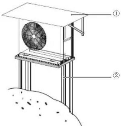
① Construct a large canopy.
② Construct a pedestal.
Install the unit high enough off the ground to prevent it from being buried in snow. (The height of the pedestal must be larger than the largest thickness of the snow in the local history plus 10cm or more)
4.3 Location Selection In Direct Sunlight
As the outdoor temperature is measured via the unit's ambient temperature sensor, make sure to install the unit in the shade or under a canopy to avoid direct sunlight, so that it is not influenced by the sun's heat, otherwise the unit may be protected.
5 INSTALLATION PRECAUTIONS
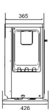
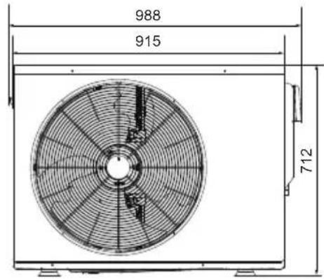
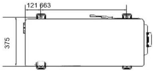
5.1 Dimensions
Model: 70/90/120
Unit: mm
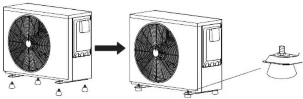
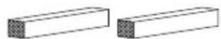
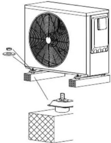
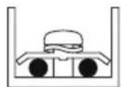
5.2 Shock absorption and fixations
- Check the strength and levelness of the installation floor, ensure that the vibration and noise of the unit are minimized.
- Bolts, nuts, gaskets, shock pads, foundations are not provided, please purchase or contact the installer.
5.2.1 Install with bolt shock pad
| Specification | QuantityNameItem | |||
 | Bolt shock pad | Bolt: M8*20-25Rubber: diameter 30 | 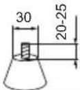 | 4 |
 | Nut | M8 | 4 | |
 | Gasket | M8 | 4 | |
natural_image
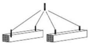
Diagram showing airflow from a two-story air duct to a multi-story fan, with a small fan nearby (no text or symbols)5.2.1 Install with perforated shock pad and bolts
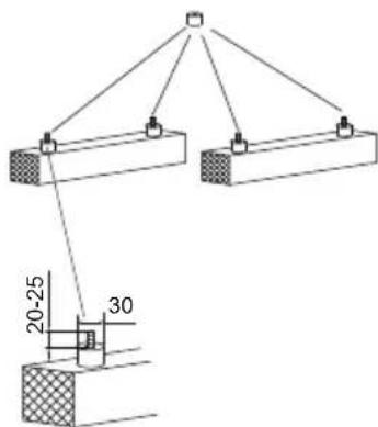
| Specification | QuantityNameltem | ||
 | Perforated shock pad | External diameter 30Inner diameter ≥ 10 | 4 |
 | 4Bolt M8 | ||
| [08KG] | Nut M8 | 4 | |
| [YZGT] | 4Gasket M8 | ||
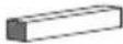 | Solid foundation W*H*L: 100*100*500 | 2 | |
1 | 2
natural_image
Simple line diagram of two rectangular blocks with diagonal lines and a central vertical bar (no text or symbols)3 | 4
4
natural_image
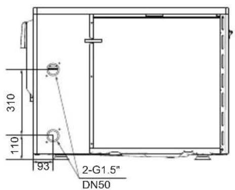
Technical line drawing of a mechanical fan assembly with mounting base and side panel (no text or symbols)5.3 Drain Hole Position
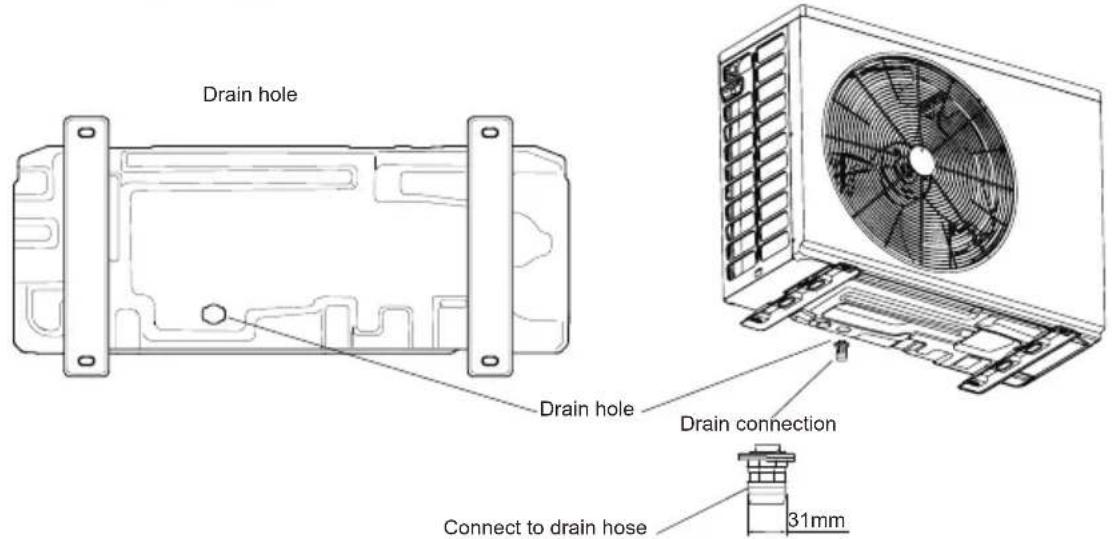
- For collecting the condensed water and discharging it centrally, please connect the unit's drain hole to drain hose (30mm) by using the Drain Connection which included in the accessory.
5.4 Inlet & Outlet Water Pipes
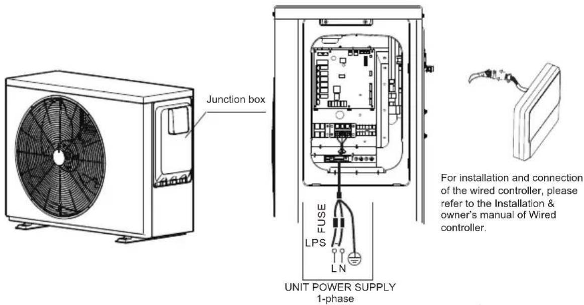
5.5 Field Wiring
NOTE
The ground fault circuit interrupter must be 1 high-speed type of 30mA(<0.1s).
Stated values are maximum values (see electrical data for exact values).
Leakage protection switch must be installed to the power supply of the unit.
Equipment must be grounded.
All high-voltage external load, if it is metal or a grounded port, must be grounded.
When connecting to the power supply terminal, use the circular wiring terminal with the insulation casing (see Figure 1).
Use power cord that conforms to the specifications and connect the power cord firmly. To prevent the cord from being pulled out by external force, make sure it is fixed securely.
If circular wiring terminal with the insulation casing cannot be used, please make sure that:
- Do not connect two power cords with different diameters to the same power supply terminal (may cause overheating of wires due to loose wiring) (See Figure 2).
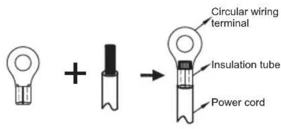
• Copper wire
Proper power wiring connections
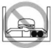
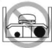
Figure 1 Figure 2
5.6 Safety Device Requirement
- For each unit, select the wire diameters according to the Wire select table and select breaker according to the MFA value of Breaker select table. In case the MCA exceeds 63A, the wire diameters should be selected according to the national wiring regulation.
- For 3 phase units, maximum allowable voltage range variation between phases is 2% .
- Select circuit breaker that having a contact separation in all poles not less than 3 mm providing full disconnection, where MFA is used to select the current circuit breakers and residual current operation breakers.
Wire select table
| Rated current of appliance: (A) | Nominal cross-sectional area ( mm^2 ) | |
| Flexible cords Cable for fixed wiring | ||
| ≤3 | 0.5 and 0.75 | 1 to 2.5 |
| >3 and ≤6 | 0.75 and 1 | 1 to 2.5 |
| >6 and ≤10 | 1 and 1.5 | 1 to 2.5 |
| >10 and ≤16 | 1.5 and 2.5 | 1.5 to 4 |
| >16 and ≤25 | 2.5 and 4 | 2.5 to 6 |
| >25 and ≤32 | 4 and 6 | 4 to 10 |
| >32 and ≤50 | 6 and 10 | 6 to 16 |
| >50 and ≤63 | 10 and 16 | 10 to 25 |
Breaker select table
| Model | Power supply | Power current | Compressor | Fan motor | |||||
| Voltage (V) | Hz MCA (A) | TOCA (A) | MFA (A) | MSC (A) | FLA (A)F | ||||
| 70 | 220-240 | 50 | 10.5 | 14 | 16 | - | 6.8 | 0.05 | 0.4 |
| 90 | 220-240 | 50 | 11 | 14 | 16 | - | 9.3 | 0.08 | 0.5 |
| 120 | 220-240 | 50 | 12 | 14 | 16 | - | 10.0 | 0.11 | 0.7 |

NOTE
MCA : Minimum. Circuit Amps. (A)
TOCA: Total Over-current Amps. (A)
MFA: Max. Fuse Amps. (A)
MSC : Max. Starting Amps. (A)
RLA: In nominal cooling or heating test condition, the input Amps of compressor where MAX. Hz can operate Rated Load Amps. (A)
kW: Rated Motor Output
FLA : Full Load Amps. (A)
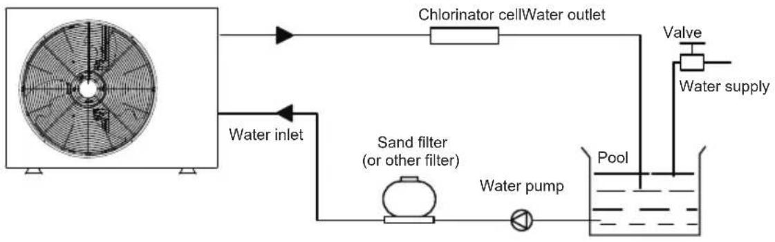
6 TYPICAL APPLICATIONS
flowchart
graph TD
    A["Fan with fan"] --> B["Chlorinator cell"]
    B --> C["Water outlet"]
    C --> D["Valve"]
    D --> E["Water supply"]
    E --> F["Pool"]
    F --> G["Water pump"]
    G --> H["Sand filter (or other filter)"]
    H --> I["Water inlet"]
Installation items:
All the items except the heat pump in the illustration are not supplied, please purchase or contact the installer.
NOTE
Please follow these steps when using for the first time
1.Open valve and charge water.
2. Make sure that the pump and the water-inlet pipe have been filled with water.
3. Close the valve and start the unit.
Attention: It is necessary that the water-inlet pipe is higher than the pool surface.
The schematic diagram is for reference only. Please check the water inlet/outlet label on the heat pump while plumbing installation.
7 OVERVIEW OF THE UNIT
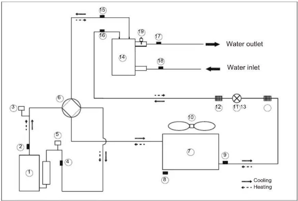
7.1 Refrigerant Cycle
flowchart
graph TD
    A["1"] --> B["2"]
    B --> C["3"]
    C --> D["4"]
    D --> E["5"]
    E --> F["6"]
    F --> G["7"]
    G --> H["8"]
    H --> I["9"]
    I --> J["10"]
    J --> K["11"]
    K --> L["12"]
    L --> M["13"]
    M --> N["Water inlet"]
    N --> O["14"]
    O --> P["15"]
    P --> Q["16"]
    Q --> R["17"]
    R --> S["Water outlet"]
    style A fill:#f9f,stroke:#333
    style B fill:#f9f,stroke:#333
    style C fill:#f9f,stroke:#333
    style D fill:#f9f,stroke:#333
    style E fill:#f9f,stroke:#333
    style F fill:#f9f,stroke:#333
    style G fill:#f9f,stroke:#333
    style H fill:#f9f,stroke:#333
    style I fill:#f9f,stroke:#333
    style J fill:#f9f,stroke:#333
    style K fill:#f9f,stroke:#333
    style L fill:#f9f,stroke:#333
    style M fill:#f9f,stroke:#333
    style N fill:#f9f,stroke:#333
    style O fill:#f9f,stroke:#333
    style P fill:#f9f,stroke:#333
    style Q fill:#f9f,stroke:#333
    style R fill:#f9f,stroke:#333
    style S fill:#f9f,stroke:#333
    style T fill:#f9f,stroke:#333
    style U fill:#f9f,stroke:#333
    style V fill:#f9f,stroke:#333
    style W fill:#f9f,stroke:#333
    style X fill:#f9f,stroke:#333
    style Y fill:#f9f,stroke:#333
    style Z fill:#f9f,stroke:#333
| Item | Description | Item | Description |
| 1 | Compressor | 11 | Electronic expansion valve |
| 2 | Discharge temperature sensor | 12 | Filter |
| 3 | High pressure switch | 13 | Filter |
| 4 | Suction temperature sensor | 14 | Titanium heat exchanger |
| 5 | Low pressure switch | 15 | Gas refrigerant temperature sensor |
| 6 | 4-way valve | 16 | Liquid refrigerant temperature sensor |
| 7 | Fin-coil heat exchanger | 17 | Water outlet temperature sensor |
| 8 | Ambient temperature sensor | 18 | Water inlet temperature sensor |
| 9 | Coil temperature sensor | 19 | Water flow switch |
| 10 | DC-fan |
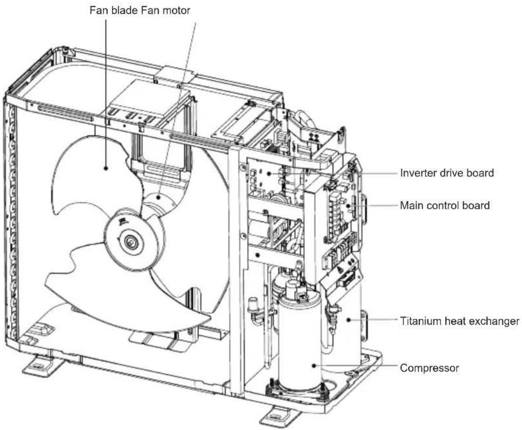
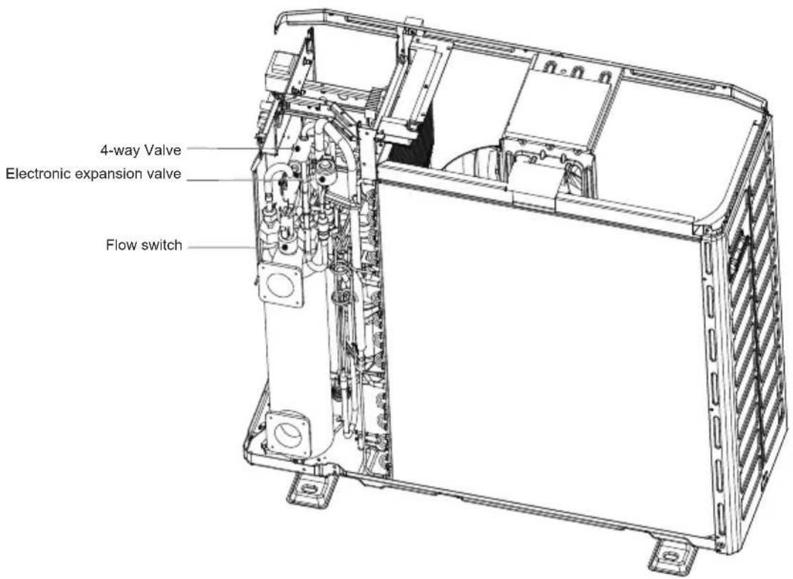
7.2 Main Components
7.3 Inverter Drive Board
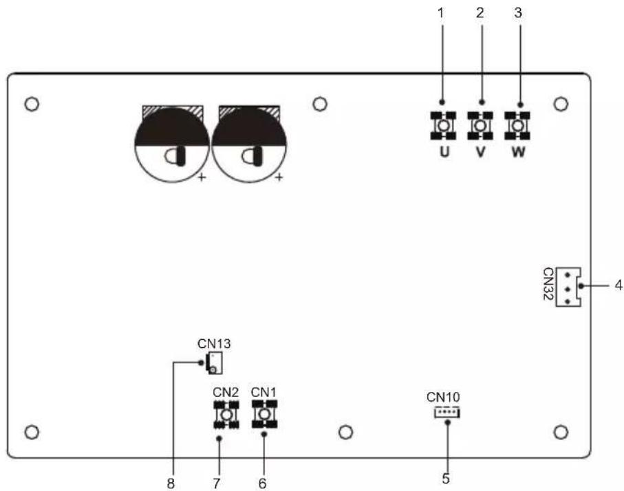
| Assembly unit Assembly unitCode | |||
| 1 | Compressor connection port U | 5 | Port for communication with main control board (CN10) |
| 2 | Compressor connection port V | 6 | Input port L for rectifier bridge(CN1) |
| 3 | Compressor connection port W | 7 | Input port N for rectifier bridge(CN2) |
| 4 | Port for fan(CN32) | 8 | Power supply port to Main control board(CN13) |
7.4 Main Control Board
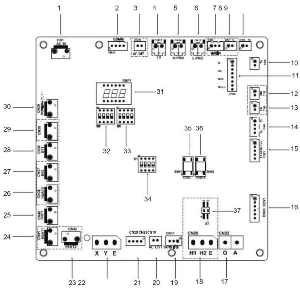
| Code | Assembly unit Assembly unitCode | ||
| 1 | Power input port from Main control board (CN1) 20 | Port for communication with wire controller AB (CN29) | |
| 2 | Port for communication with Inverter module (CN43) | 21 | Port for transformer output(CN28) |
| 3 | Port for flow remote switch((CN15) Reserved(CN19) | 22 | |
| 4 | Port for flow switch(CN16) | 23 | Reserved(CN42) |
| 5 | Port for high pressure switch (CN18) | 24 | Reserved(CN41) |
| 6 | Port for low pressure switch (CN17) | 25 | Port for transformer input(CN40) |
| 7 | Port for high pressure sensor(CN3) (Reserved) | 26 | Reserved(CN38) |
| 8 | Port for TL temperature sensor(CN7) (Reserved) | 27 | Reserved (CN37) |
| 9 | Port for TH temp.sensor(CN5) | 28 | Port for 4-way valve(CN36) |
| 10 | Port for TP temp.sensor(CN4) | 29 | Port for plate heater(CN35) |
| 11 | Port for T2,T2B,TW-in,TW-out temp.sensor(CN10) | 30 | Port for PUMP(CN39) |
| 12 | temperature sensor(CN9) (Reserved) | 31 | Digital display(DSP1) |
| 13 | temperature sensor(CN8) (Reserved) | 32 | Dip switch S5 |
| 14 | Port for T3,T4 temp.sensor(CN6) | 33 | Dip switch S6 |
| 15 | Port for EEV3/SG EVU(CN23) | 34 | Dip switch S1 |
| 16 | Port for electrical expansion valve1(CN33) | 35 | Port for forced cooling(SW1) |
| 17 | Port for communication with ammeter(CN22) (Reserved) | 36 | Port for point check(SW2) |
| 18 | Port for communication with outdoor unit (CN20) (Reserved) | 37 | Dip switch S7(Reserved) |
| 19 | Port for communication with wire controller PQE (CN11) |
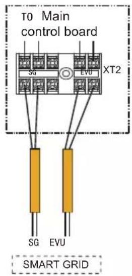
7.5 Connection Of Optional Function
1) For smart grid:
The unit has smart grid function, there are two ports on PCB to connect SG signal and EVU signal as following:
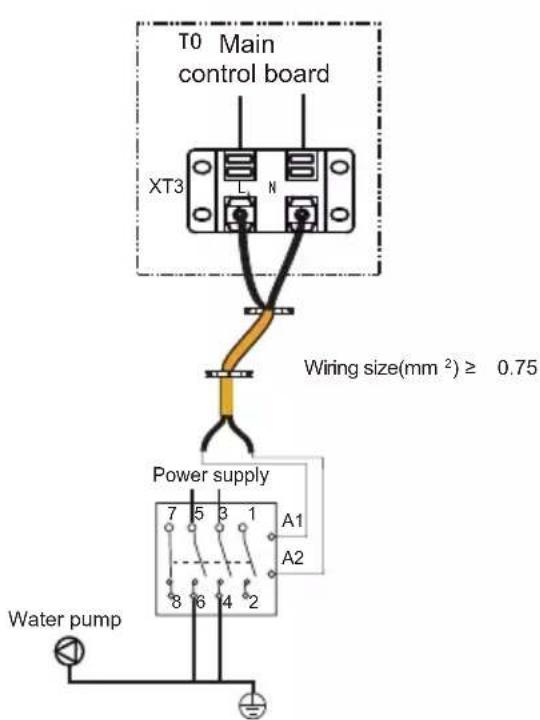
2) For outside pump :
1) SG=ON, EVU=ON.
If the heat pump in heating mode:
•The heat pump automatically activates the boost function.
2) SG=OFF, EVU=ON.
If the heat pump in heating mode:
- The heat pump automatically activates the boost function.
3) SG=ON, EVU=OFF.
The unit will operate normally.
4) SG=OFF, EVU=OFF.
The maximum running hours of the compressor does not exceed the parameter of SMART GRID RUNNING TIME. SMART GRID RUNNING TIME initial value is 2, range 0-255.
3) For remote switch
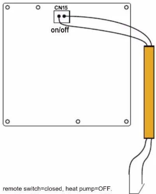
remote switch=closed, heat pump=OFF. remote switch=opened, heat pump=ON.
8 START-UP AND CONFIGURATION
The unit should be configured by the installer to match the installation environment (outdoor climate, installed options, etc.) and user expertise.
CAUTION
It is important that all information in this chapter is read sequentially by the installer and that the system is configured as applicable.
8.1 Initial Start-up At Low Outdoor Ambient Temperature
During initial start-up and when water temperature is low, it is important that the water is heated gradually.
8.2 Pre-operation Checks
Checks before initial start-up.
DANGER
Switch off the power supply before making any connections.
After the installation of the unit, check the following before switching on the circuit breaker:
- Field wiring: Make sure that the field wiring between the local supply panel and unit and valves (when applicable) have been connected according to the wiring diagrams and to local laws and regulations.
- Fuses, circuit breakers, or protection devices Check that the fuses or the locally installed protection devices are of the size and type specified in “TECHNICAL SPECIFICATIONS”.
- Make sure that no fuses or protection devices have been bypassed.
- Ground wiring: Make sure that the ground wires have been connected properly and that the ground terminals are tightened.
- Internal wiring: Visually check the switch box for loose connections or damaged electrical components.
- Mounting: Check that the unit is properly mounted, to avoid abnormal noises and vibrations when starting up the unit.
- Damaged equipment: Check the inside of the unit for damaged components or squeezed pipes.
- Refrigerant leak: Check the inside of the unit for refrigerant leakage. If there is a refrigerant leak, call your local dealer.
- Power supply voltage: Check the power supply voltage on the local supply panel. The voltage must correspond to the voltage on the identification label of the unit.
- Shut-off valves: Make sure that the shut-off valves are fully open.
8.3 Failure Diagnosis At First Installation
- If nothing is displayed on the user interface, it is necessary to check for any of the following abnormalities before diagnosing possible error codes.
-Disconnection or wiring error (between power supply and unit and between unit and user interface).
-The fuse on the PCB may be broken. - If the user interface shows "E8" or "E0" as an error code, there is a possibility that there is air in the system, or the water level in the system is less than the required minimum.
- If the error code E2 is displayed on the user interface, check the wiring between the user interface and unit.
• More error code and failure causes can be found in 12 "Error codes".
9 FINAL CHECKS AND TEST RUN
The installer is obliged to verify correct operation of unit after installation
Final checks
Before switching on the unit, read following recommendations:
- When the installation and parameter setting are completed, cover all the sheet metal of the unit well.
• The unit should be maintained by professionals
10 MAINTENANCE AND SERVICE
In order to ensure optimal availability of the unit, a number of checks and inspections on the unit and the field wiring have to be carried out at regular intervals
This maintenance needs to be carried out by your local technician.
DANGER
• Before carrying out any maintenance or repairing activity, must switch off the power supply on the supply panel.
- Do not touch any live part for 10 minutes after the power supply is turned off.
• The crank heater of compressor may operate even in standby.
- Please note that some sections of the electric component box are hot.
• Forbid touch any conductive parts.
- Forbid rinse the unit. It may cause electric shock or fire.
- Forbid leave the unit unattended when service panel is removed.
• Refrigerant supplement:
-Each unit has been equipped with sufficient refrigerant when leaving the factory.Do not charge or change the refrigerant.If you need to replenish the refrigerant due to leakage, please contact the engineer or dealer.
- Do not change the system parameters before consulting the engineer.
- Ensure the waterways are clean and avoid dirt and blockage.
- Please use the parts provided or recommended by the company, do not use the parts unqualified.
10.1 Routine Maintenance
The following checks must be performed at least once a year by qualified person.
• Thoroughly inspect and clean up the unit.
- Water filter
-Clean the waterway system.
-Clean the water filter.
-Check water pump, regulating valve and other waterway equipment.
- Unit switch box
-Carry out a thorough visual inspection of the switch box and look for obvious defects such as loose connections or defective wiring.
-Check for correct operation of contactors with an ohm meter. All contacts of these contactors must be in open position.
Winter antifreeze
-If the unit is not operation in winter, remove the inlet and outlet water connections and let off the water of the unit.
10.2 Notes For Maintenance & Repair
10.2.1 Top panel remove
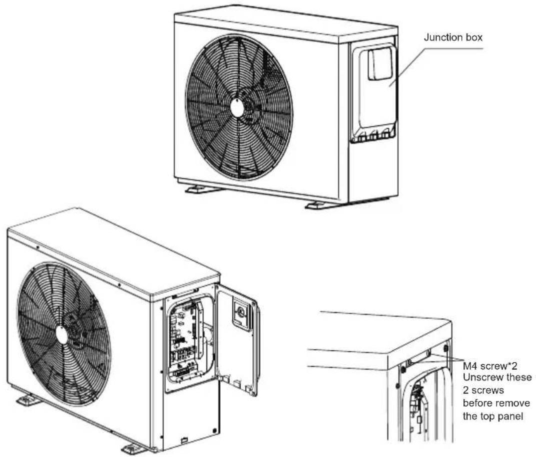
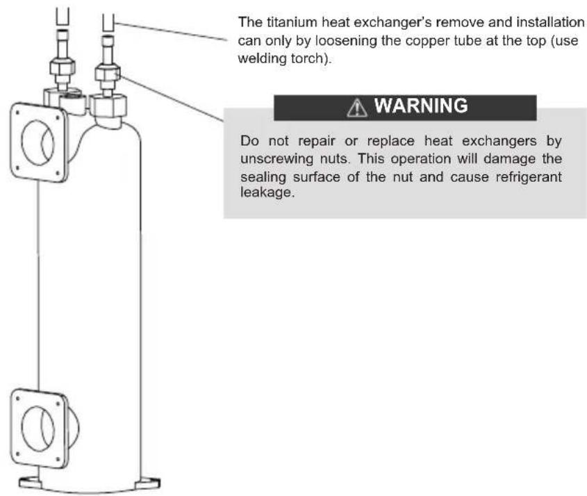
10.2.2 Titanium heat exchanger replace
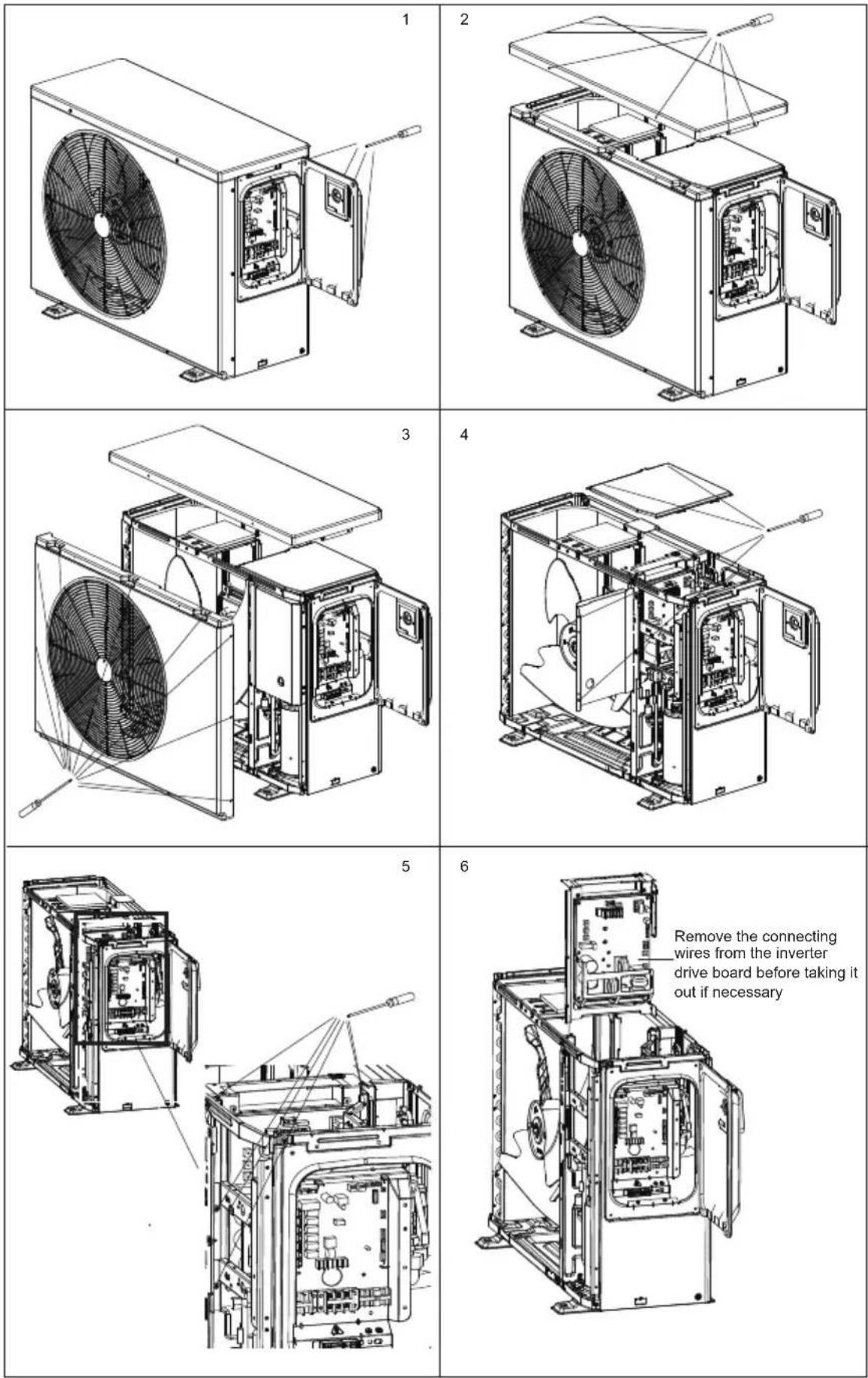
10.2.3 Inverter drive board replace
11 TROUBLESHOOTING
Error code
| NO. | Display Malfunction or Protection | |
| 1 | bA | Ambient temp. sensor (T4) out of operation range |
| 2 | C7 | High temperature protection of inverter module |
| 3 | E0 | Water flow malfunction(after 3 times E8) |
| 4 | E2 | Communication malfunction between controller and main control board |
| 5 | E3 | Total outlet water temp.sensor(T1) malfunction |
| 6 | E5 | Air side heat exchanger temperature sensor (T3)malfunction |
| 7 | E6 | The ambient temperature sensor (T4)malfunction |
| 8 | E8 | Water flow malfunction |
| 9 | E9 | Suction temperature sensor(Th) malfunction |
| 10 | EA | Discharge temperature sensor(Tp) malfunction |
| 11 | Ed | Inlet water temp.sensor (Tw_in) malfunction |
| 12 | EE | EEProm malfunction |
| 13 | F1 | DC bus low voltage protection |
| 14 | F6 | EXV1 fault |
| 15 | H1 | Communication malfunction between main control board and inverter board |
| 16 | H2 | Liquid refrigerant temp.sensor(T2) malfunction |
| 17 | H3 | Gas refrigerant temp.sensor(T2B) malfunction |
| 18 | H4 | Three times L0 protects |
| 19 | H6 | The DC fan malfunction |
| 20 | H7 | Voltage protection |
| 21 | H8 | HP pressure sensor malfunction |
| 22 | HA | Outlet water temp.sensor (Tw_out) malfunction |
| 23 | Hb | Three times PP protection and Tw_out below 7 °C |
| 24 | HF | Inverter module board EE prom malfunction |
| 25 | HH | 10 times H6 in 2 hours |
| 26 | HP | Low pressure protection in cooling mode |
| 27 | P0 | Low pressure switch protection |
| 28 | P1 | High pressure switch protection |
| 29 | P3 | Compressor overcurrent protection |
| 30 | P4 | Comp discharge temp. too high protection |
| 31 | P5 | |Tw_out-Tw_in| value too big protection |
| 32 | Pb | Anti-freeze mode |
| 33 | PP | |Tw_out-Tw_in| abnormal protection |
| 34 | Pd | High temperature protection of air side heat exchanger temperature(T3) |
| 35 | L0 | Inverter or compressor protection |
| 36 | L1 | DC bus low voltage protection |
| 37 | L2 | DC bus high voltage protection |
| 38 | L3 | Current sampling error of PFC circuit |
| 39 | L4 | Rotating stall protection |
| 40 | L5 | Zero speed protection |
| 41 | L7 | Phase loss protection of compressor |
Common malfunctions/protections and solutions in heating mode
| NO. | Error code | Malfunction / protection | Solutions |
| 1 | E2 | Communication failure | 1. Restart the unit.2. Power off the unit,unplug and plug the cable of display, and then power on.3. If all the above checks are ok, the fault still exists, please contact the installer or retailer. |
| 2 | E8 | Water flow protection | 1. Check whether the water pump works properly.2. Check whether there is no water flow or water flow is too low.3. If all the above checks are ok, the fault still exists, please contact the installer or retailer. |
| 3 | P5 | The temperature difference between inlet and outlet is too large | 1. Check whether the water pump works properly.2. Check whether there is no water flow or water flow is too low.3. If all the above checks are ok, the fault still exists, please contact the installer or retailer. |
| 4 | bA | Ambient temp. Out of operation range | 1. Check whether the ambient temperature is lower than the operating range of the unit.2. Check whether the finned heat exchanger and air outlet of the unit are blocked by debris.3. Check whether the ambient temperature probe is detached or attached to the fin.4. If all the above checks are ok, the fault still exists, please contact the installer or retailer. |
| 5 | P1 | High pressure protection | 1. Check whether the water pump works properly.2. Check whether there is no water flow or water flow is too low.3. If all the above checks are ok, the fault still exists, please contact the installer or retailer. |
| 6 | P0 | Low pressure protection | 1. Check whether the fan is running properly.2. Check whether the finned heat exchanger and air outlet of the unit are blocked by debris.3. If all the above checks are ok, the fault still exists, please contact the installer or retailer. |
12 TECHNICAL SPECIFICATIONS
| Model | 70 90 | 120 | ||
| Power supply | 220-240V~50Hz | |||
| Boost Heating capacity* | kW | 10.50 | 12.80 | 14.50 |
| Boost COP* | 6.70 | 6.00 | 6.35 | |
| Heating capacity* | kW | 7.16 | 9.15 | 12.50 |
| COP* | 7.60 | 6.90 | 7.00 | |
| Boost Heating capacity** | kW | 7.50 | 9.30 | 10.70 |
| Boost COP** | 4.75 | 4.45 | 4.65 | |
| Heating capacity** | kW | 5.30 | 6.80 | 9.12 |
| COP** | 5.10 | 4.90 | 5.05 | |
| Cooling capacity | kW | 4.50 | 5.20 | 7.00 |
| EER | 4.00 | 3.35 | 4.00 | |
| Sound pressure level (1m) | dB(A) | 41 | 43 | 49 |
| Silence mode sound pressure level (1m) | dB(A) | 39 | 39 | 40 |
| Water flow | m^3/h | 3.1 | 3.9 | 5.4 |
| Water pressure drop | kPa | 4.6 | 7.3 | 13.8 |
| Heating condition*: ambient temp. DB27°C, WB24.3°C; water outlet temp. 28°CHeating condition**: ambient temp. DB15°C, WB12°C; water outlet temp.28°CCooling condition: ambient temp. DB35°C, WB24°C; water outlet temp.28°CSound pressure test condition: ambient temp. DB27°C, WB24.3°C; water outlet temp. 28°C | ||||
Note: The data in the performance table are for reference only, the exact data are on the nameplate.
13 INFORMATION SERVICING
1) Checks to the area
Prior to beginning work on systems containing flammable refrigerants, safety checks are necessary to ensure that the risk of ignition is minimised. For repair to the refrigerating system, the following precautions shall be complied with prior to conducting work on the system.
2) Work procedure
Works shall be undertaken under a controlled procedure so as to minimise the risk of a flammable gas or vapour being present while the work is being performed.
3) General work area
All maintenance staff and others working in the local area shall be instructed on the nature of work being carried out. work in confined sapces shall be avoided. The area around the work space shall be sectioned off. Ensure that the conditions within the area have been made safe by control of flammable material.
4) Checking for presence of refrigerant
The area shall be checked with an appropriate refrigerant detector prior to and during work, to ensure the technician is aware of potentially flammable atmospheres. Ensure that the leak detection equipment being used is suitable for use with flammable refrigerants, i.e. no sparking, adequately sealed or intrinsically safe.
5) Presence of fire extinguisher
If any hot work is to be conducted on the refrigeration equipment or any associated parts, appropriate fire extinguishing equipment shall be available to hand. Have a dry power or CO2 fire extinguisher adjacent to the charging area.
6) No ignition sources
No person carrying out work in relation to a refrigeration system which involves exposing any pipe work that contains or has contained flammable refrigerant shall use any sources of ignition in such a manner that it may lead to the risk of fire or explosion.
All possible ignition sources, including cigarette smoking, should be kept sufficiently far away from the site of installation, repairing, removing and disposal, during which flammable refrigerant can possibly be released to the surrounding space. Prior to work taking place, the area around the equipment is to be surveyed to make sure that there are no flammable hazards or ignition risks. NO SMOKING signs shall be displayed.
7) Ventilated area
Ensure that the area is in the open or that it it adequately ventilated before breaking into the system or conducting any hot work.
A degree of ventilation shall continue during the period that the work is carried out. The ventilation should safely disperse any released refrigerant and preferably expel it externally into the atmosphere.
8) Checks to the refrigeration equipment
Where electrical components are being changed, they shall be fit for the purpose and to the correct specification. At all times the manufacturer's maintenance and service guidelines shall be followed. If in doubt consult the manufacturer's technical department for assistance. The following checks shall be applied to installations using flammable refrigerants.
9) Checks to electrical devices
Repair and maintenance to electrical components shall include initial safety checks and component inspection procedures. If a fault exists that could compromise safety, then no electrical supply shall be connected to the circuit until it is satisfactorily dealt with. If the fault cannot be corrected immediately but it is necessary to continue operation, and adequate temporary solution shall be used. This shall be reported to the owner of the equipment so all parties are advised.
Initial safety checks shall include:
The charge size is in accordance with the room size within which the refrigerant containing parts are installed.
The ventilation machinery and outlets are operating adequately and are not obstructed.
If an indirect refrigerating circuit is being used, the secondary circuits shall be checked for the presence of refrigerant; marking to the equipment continues to be visible and legible.
Marking and signs that are illegible shall be corrected.
Refrigeration pipe or components are installed in a position where they are unlikely to be exposed to any substance which may corrode refrigerant containing components, unless the components are constructed of materials which are inherently resistant to being corroded or are suitably protected against being so corroded.
That capacitors are discharged: this shall be done in a safe manner to avoid possibility of sparking.
That there no live electrical components and wiring are exposed while charging, recovering or purging the system.
That there is continuity of earth bonding.
10) Repairs to sealed components
Ensure that apparatus is mounted securely.
Ensure that seals or sealing materials have not degraded such that they no longer serve the purpose of preventing the ingress of flammable atmospheres. Replacement parts shall be in accordance with the manufacturer's specifications.
11) Repair to intrinsically safe components
Do not apply any permanent inductive or capacitance loads to the circuit without ensuring that this will not exceed the permissible voltage and current permitted for the equipment in use. Intrinsically safe components are the only types that can be worked on while live in the presence of a flammable atmosphere. The test apparatus shall be at the correct rating. Replace components only with parts specified by the manufacturer. Other parts may result in the ignition of refrigerant in the atmosphere from a leak.
12) Cabling
Check that cabling will not be subject to wear, corrosion, excessive pressure, vibration, sharp edges or any other adverse environmental effects. The check shall also take into account the effects of aging or continual vibration from sources such as compressors or fans.
13) Detection of flammable refrigerants
Under no circumstances shall potential sources of ignition be used in the searching for or detection of refrigerant leaks. A halide torch (or any other detector using a naked flame) shall not be used.
14) Leak detection methods
The following leak detection methods are deemed acceptable for systems containing flammable refrigerants. Electronic leak detectors shall be used to detect flammable refrigerants, but the sensitivity may not be adequate, or may need re-calibration.(Detection equipment shall be calibrated in a refrigerant-free area.) Ensure that the detector is not a potential source of ignition and is suitable for the refrigerant. Leak detection equipment shall be set at a percentage of the LFL of the refrigerant and shall be calibrated to the refrigerant employed and the appropriate percentage of gas (25% maximum) is confirmed. Leak detection fluids are suitable for use with most refrigerants but the use of detergents containing chlorine shall be avoided as the chlorine may react with the refrigerant and corrode the copper pipe-work. If a leak is suspected ,all naked flames shall be removed or extinguished. If a leakage of refrigerat is found which requires brazing, all of the refrigerant shall be recovered from the system, or isolated(by means of shut off valves) in a part of the system remote from the leak . Oxygen free nitrogen(OFN) shall then be purged through the system both before and during the brazing process.
15) Removal and evacuation
When breaking into the refrigerant circuit to make repairs of for any other purpose conventional procedures shall be used, However, it is important that best practice is followed since flammability is a consideration. The following procedure shall be adhered to:
Remove refrigerant;
Purge the circuit with inert gas;
Evacuate;
Purge again with inert gas;
Open the circuit by cutting or brazing.
The use of silicon sealant may inhibit the effectiveness of some types of leak detection equipment. Instrinsically safe components do not have to be isolated prior to working on them.
NOTE
The refrigerant charge shall be recovered into the correct recovery cylinders. The system shall be flushed with OFN to render the unit safe. This process may need to be repeated several times.
Compressed air or oxygen shall not be used for this task.
Flushing shall be achieved by breaking the vacuum in the system with OFN and continuing to fill until the working pressure is achieved, then venting to atmosphere, and finally pulling down to a vacuum. This process shall be repeated until no refrigerant is within the system.
When the final OFN charge is used, the system shall be vented down to atmospheric pressure to enable work to take place.
This operation is absolutely vital if brazing operations on the pipe-work are to take place.
Ensure that the outlet for the vacuum pump is not closed to any ignition sources and there is ventilation available.
16) Charging procedures
In addition to conventional charging procedures, the following requirements shall be followed:
Ensure that contamination of different refrigerants does not occur when using charging equipment. Hoses or lines shall be as short as possible to minimize the amount of refrigerant contained in them.
Cylinders shall be kept upright.
Ensure that the refrigeration system is earthed prior to charging the system with refrigerant.
Label the system when charging is complete(if not already).
Extreme care shall be taken not to overfill the refrigeration system.
Prior to recharging the system it shall be pressure tested with OFN. The system shall be leak tested on completion of charging but prior to commissioning. A follow up leak test shall be carried out prior to leaving the site.
17) Decommissioning
Before carrying out this procedure, it is essential that the technician is completely familiar with the equipment and all its detail.
It is recommended good practice that all refrigerants are recovered safely. Prior to the task being carried out, an oil and refrigerant sample shall be taken.
In case analysis is required prior to re-use of reclaimed refrigerant. It is essential that electrical power is available before the task is commenced.
a) Become familiar with the equipment and its operation.
b) Isolate system electrically
c) Before attempting the procedure ensure that:
Mechanical handling equipment is available, if required, for handling refrigerant cylinders.
All personal protective equipment is available and being used correctly.
The recovery process is supervised at all times by a competent person.
Recovery equipment and cylinders conform to the appropriate standards.
d) Pump down refrigerant system, if possible.
e) If a vacuum is not possible, make a manifold so that refrigerant can be removed from various parts of the system.
f) Make sure that cylinder is situated on the scales before recovery takes place.
g) Start the recovery machine and operate in accordance with manufacturer's instructions.
h) Do not overfill cylinders. (No more than 80% volume liquid charge).
i) Do not exceed the maximum working pressure of the cylinder, even temporarily.
j) When the cylinders have been filled correctly and the process completed, make sure that the cylinders and the equipment are removed from site promptly and all isolation valves on the equipment are closed off.
k) Recovered refrigerant shall not be charged into another refrigeration system unless it has been cleaned and checked.
18) Labelling
Equipment shall be labelled stating that it has been de-commissioned and emptied of refrigerant. The label shall be dated and signed. Ensure that there are labels on the equipment stating the equipment contains flammable refrigerant.
19) Recovery
When removing refrigerant from a system, either for service or decommissioning, it is recommended good practice that all refrigerants are removed safely.
When tranferring refrigerant into cylinders, ensure that only appropriate refrigerant recovery cylinders are employed. Ensure that the correct numbers of cylinders for holding the total system charge are available. All cylinders to be used are designated for the recovered refrigerant and labelled for that refrigerant(i.e special cylinders for the recovery of refrigerant). Cylinders shall be complete with pressure relief valve and associated shut-off valves in good working order.
Empty recovery cylinders are evacuated and, if possible, cooled before recovery occurs.
The recovery equipment shall be in good working order with a set of instructions concerning the equipment that is at hand and shall be suitable for the recovery of flammable refrigerants. In addition, a set of calibrated weighing scales shall be available and in good working order.
Hoses shall be complete with leak-free disconnect couplings and in good condition. Before using the recovery machine, check that it is in satisfactory working order, has been properly maintained and that any associated electrical components are sealed to prevent ignition in the event of a refrigerant release. Consult manufacturer if in doubt.
The recovered refrigerant shall be returned to the refrigerant supplier in the correct recovery cylinder, and the relevant Waste Transfer Note arranged. Do not mix refrigerants in recovery units and especially not in cylinders.
If compressors or compressor oils are to be removed, ensure that they have been evacuated to an acceptable level to make certain that flammable refrigerant does not remain within the lubricant. The evacuation process shall be carried out prior to retruning the compressor to the suppliers. Only electric heating to the compressor body shall be employed to accelerate this process. When oil is drained from a system, it shall be carried out safely.
20) Transportation, marking and storage for units
Transport of equipment containing flammable refrigerants Compliance with the transport regulations.
Marking of equipment using signs Compliance with local regulations.
Disposal of equipment using flammable refrigerants Compliance with national regulations.
Storage of equipment/appliances.
The storage of equipment should be in accordance with the manufacturer's instructions.
Storage of packed (unsold) equipment.
Storage package protection should be constructed such that mechanical damage to the equipment inside the package will not cause a leak of the refrigerant charge.
The maximum number of pieces of equipment permitted to be stored together will be determined by local regulations.
European Disposal Guidelines
To protect our environment and to recycle the raw materials used completely as possible, the consumer is asked to return unserviceable equipment to the public collection system
as
for electrical and electronic.
The symbol of the crossed indicates that this product must be returned to the collection point for electronic waste to feed it by recycling the best possible raw material recycling.
By ensuring this product you will prevent possible negative effects on the environment and human health, which could otherwise be caused due to improper disposal of that product. The recycling of materials from this product, you will help to preserve a healthy environment and natural resources.
For detailed information about the collection of EE products contact M SAN Grupa d.o.o. or the dealer where you purchased the product.
This appliance contains refrigerant and other potentially hazardous materials. When disposing of this appliance, the law requires special collection and treatment. Do not dispose of this product as household waste or unsorted municipal waste.
When disposing of this appliance, you have the following options:
- Dispose of the appliance at designated municipal electronic waste collection facility.
- When buying a new appliance, t he retailer will take back the old appliance free of charge.
- The manufacturer will take back the old appliance free of charge.
- Sell the appliance to certified scrap metal dealers.
Special notice
Disposing of this appliance in the forest or other natural surroundings endangers your health and is bad for the environment. Hazardous substances may leak into the ground water and enter the food chain.
EU Declaraton of Conformity
This device is manufactured in accordance with the applicable European standards and in accordance with all applicable Directives and Regulations.

EU declaration of conformity can be downloaded from the following link: www.msan.hr/dokumentacijaartikala
POŠTOVANI!
Zahvaljujemo na kupnji VIVAX uređaja i nadamo se da ćete biti zadovoljni odabirom. Ako u jamstvenom roku bude potreban popravak proizvoda, molimo savjetujte se sa ovlaštenim prodavačem koji Vam je proizvod prodao ili nas kontaktirajte na dolje navedene brojeve i adrese. MOLIMO VAS DA PRIJE UPORABE PROIZVODA PAŽLJIVO PROČITATE UPUTE PRILOŽENE UZ PROIZVOD!
JAMSTVENI LIST HR
VIVAX
MODEL UREĐAJA
SERIJSKI BROJ
DATUM PRÓDAJE
BROJ RAČUNA PRODAVATELJA
POTPIS I PEČAT PRODAVATELJA
- Preuzimamo obavezu besplatno popraviti ili zamijeniti neispravne dijelove VIVAX klima uređaja koji bi se takvim pokazali za vrijeme trajanja jamstva, kao greška prilikom izrade ili montaže. Ovim jamstvom jamčimo da će predmet ovog jamstva raditi bez pogreške uzrokovane eventualnom lošom izradom ili lošim materijalom izrade. Svi, eventualno nastali, kvarovi biti će besplatno otklonjeni od strane ovlaštenog servisa u jamstvenom roku.
UVJETI JAMSTVA:
-
Jamstveni rok počinje od dana kupnje proizvoda i traje 24 mjeseca, osim modela ACP-xxxxCCxxxxxx, ACP-xxxxCTxxxxxx, ACP-xxxxDTxxxxxx, ACP-xxxxCFxxxxxx, ACP-xxxxFSxxxxxx, HPM-xxCHxxAERI, HPS-xxCHxxAERI za koje vrijedi jamstvo u trajanju od 12 mjeseci
-
Jamstvo na uređaje u upotrebi produžuje se za sljedećih 12 mjeseci nakon izvršenja jamstvenog servisnog pregleda od strane ovlaštenog servisa.
- Jamstvo se može produljivati ukupno tri puta, osim modela ACP-xxxxCCxxxxx, ACP-xxxxCTxxxxx, ACP-xxxxDTxxxxx, ACP-xxxxCFxxxxx, ACP-xxxxFSxxxxx, HPM-xxCHxxAERI, HPS-xxCHxxAERI za koje se jamstvo može produljivati četiri puta, što u ukupnom trajanju može iznositi maksimalno 60 mjeseci
- Jamstveni servisni pregled naplaćuje ovlašteni servis po cjeniku zastupnika M SAN Grupa d.o.o. i ovjerava jamstveni list što dokazuje produljenje i valjanost jamstva.
- Jamstvo vrijedi ako su montaža ili servis VIVAX klima uređaja obavljeni od strane ovlaštenog servisa kojeg je ovlastio zastupnik M SAN Grupa d.o.o.
- VIVAX klima uređaj kao cjelinu čine jedna ili više unutarnjih jedinica, instalacija i vanjska jedinica koje su pravilno odabrani i koji si međusobno odgovaraju po modelu i snazi.
- U slučaju kvara na proizvodu koji je predmet ovog jamstva, obvezujemo se da ćemo isti popraviti u najkraćem mogućem roku, a najkasnije u roku od 45 dana. Ako se proizvod ne može popraviti ili se ne popravi u roku od 45 dana, biti će zamijenjen novim. Jamstvo će biti produljeno za vrijeme trajanja popravka.
- Jamstvo se priznaje samo uz račun o kupnji, te uz ovaj jamstveni list koji mora biti ispravno popunjen odnosno mora sadržavati datum prodaje, pečat i potpis prodavatelja, ovlaštenog montažera ili servisera.
- Davalac jamstva osigurava servis i rezervne dijelove 5 godina od datuma kupnje VIVAX klima uređaja JAMSTVO NE OBUHVAĆA:
- Redovnu provjeru, održavanje uz zamjenu dijelova koji se troše normalnom upotrebom, prilagođavanje ili promjene za poboljšanje proizvoda za primjenu koji nisu opisane u tehničkim uputama za korištenje, osim ako je za te preinake predočena suglasnost M SAN GRUPA d.o.o.
- Jamstvo se ne priznaje u sljedećim slučajevima:
BROJ RAČUNA PRODAVAOCA
POTPIS I PEČAT PRODAVAOCA
- Preuzimamo obavezu da besplatno popravimo ili zamijenimo neispravne dijelove Vivax cool klima uređaja koji bi se takvim pokazali za vrijeme trajanja garancije, kao greška prilikom izrade ili montaže
Ovom garancijom garantujemo da će predmet ove garancije raditi bez pogreške uzrokovane eventualnom lošom izradom ili lošim materijalom izrade. Svi, eventualno nastali, kvarovi biće besplatno otklonjeni u ovlaštenom servisu u garantnom roku.
USLOVI GARANCIJE:
-
Garancija na Vivax cool klima uređaje počinje teći od dana kupovine proizvoda i traje 24 mjeseca, osim modela ACP-xxxxCCxxxxxx, ACP-xxxxCTxxxxxx, ACP-xxxxDTxxxxxx, ACP-xxxxCFxxxxxx, ACP-xxxxFSxxxxxx, HPM-xxCHxxAERI, HPS-xxCHxxAERI za koje vrijedi garancija u trajanju od 12 mjeseci
-
Garancija na uređaje u upotrebi produžuje se za sljedećih 12 mjeseci nakon izvršenja garantnog servisnog pregleda od strane ovlaštenog servisa.
-
Garancija se može produžavali ukupno tri puta, osim modela ACP-xxxxCCxxxxx, ACP-xxxxCTxxxxx, ACP-xxxxDTxxxxx, ACP-xxxxCFxxxxx, ACP-xxxxFSxxxxx, HPM-xxCHxxAERI, HPS-xxCHxxAERI za koje se garancija može produljivati četiri puta, što u ukupnom trajanju može iznositi maksimalno 60 mjeseci
-
Garantni servisni pregled naplaćuje ovlašteni servis po cjenovniku zastupnika KimTec d.o.o. i/ili Kim Tec servis d.o.o. i ovjerava garantni list što dokazuje produženje i valjanost garancije
-
Garancija vrijedi ako su montaža ili servis Vivax cool klima uređaja obavljeni od strane ovlaštenog servisa kojeg je ovlastio zastupnik Kimtec d.o.o..
-
Vivax cool klima uređaj kao cjelinu čine unutarnja jedinica, instalacija i vanjska jedinica koji su pravilno odabrani i koji međusobno odgovaraju po modelu i snazi.
-
U slučaju kvara na Vivax cool klima uređaju obvezujemo se da ćemo isti popraviti u najkraćem mogućem roku, a najkasnije u roku 30 dana, ako se Vivax cool klima uređaj ne može popraviti ili se ne popravi u roku od 30 dana, biće zamijenjen novim. Ako popravak Vivax cool klima uređaja traje duže od 10 dana, garancija će sa produžiti za vrijeme trajanja popravka.
-
Garancija se priznaje samo uz račun o kupovini, te uz ovaj garantni list koji mora bili ispravno popunjen i ovjeren od strane prodavca, ovlaštenog montažera ili servisera.
-
Davaoc garancije osigurava servis i rezervne dijelova 7 godina od datuma kupnje Vivax cool klima uređaj
11. GARANCIJA NE OBUHVATA:
Redovnu provjeru, održavanje uz zamjenu dijelova koji se troše normalnom upotrebom, prilagođavanje ili promjene za poboljšanje proizvoda za primjenu koji nisu opisane u tehničkim uputstvima za korištenje, osim ako je za te preinake predočena saglasnost M SAN GRUPA d.o.o.; i KimTec d.o.o. i/ili Kim Tec servis d.o.o.
12. Garancija se ne priznaje u sljedećim slučajevima:
Ako kupac ne predoči ispravan garantni list i račun o kupovini.
POTPIS I PEČAT PRODAVCA
- Ovom izjavom o saobraznosti proizvođač proizvoda, preko KIM TEC CG d.o.o., kao uvoznika i davaoca prava u Crnoj Gori osigurava besplatan popravak istog u skladu s vazečim propisima i u skladu s uslovima opisanim u ovoj izjavi o saobraznosti.
- Ovom izjavom o saobraznosti ističemo da će predmet ovog prava raditi bez greške uzrokovane eventualnom lošom Izradom i lošim materijalom izrade. Svi eventualno nastali kvarovi biće besplatno otklonjeni u ovlašcenom servisu u predvidjenom roku za reklamaciju.
- Rok za reklamaciju proizvoda počinje od dana kupovine proizvoda i traje 24 mjeseca.
- Rok za reklamaciju proizvoda u upotrebi produžuje se za sljedećih 12 mjeseci nakon izvršenja kontrolnog servisnog pregleda od strane ovlašćenog servisa.
- Rok za reklamaciju proizvoda može se produžavati ukupno tri puta, što u ukupnom trajanju može iznositi maksimalno 60 mjeseci
- U slučaju kvara na proizvodu koji je predmet reklamacije, obavezujemo se da ćemo isti popraviti u najkraćem mogućem roku, a najkasnije u roku od 15 dana. Ako se proizvod ne može popraviti ili se ne popravi u roku od 15 dana, biće zamijenjen novim.
- Pravo na reklamaciju se priznaje uz fiskalni račun o kupovini, ili uz ovu izjavu o saobraznosti koji mora biti ispravno popunjen odnosno mora sadržati datum prodaje, pečat i potpis prodavca.
- Davalac izjave o saobraznosti osigurava servis i rezervne djelove u razumno vremenskom periodu.
PRAVO NA REKLAMACIJU NE OBUHVATA

- INSTALLATION AND OWNER'S MANUAL
- RECOGNIZE THIS SYMBOL AS AN INDICATION OF IMPORTANT SAFETY INFORMATION
- WARNING
- CAUTION
- CONTENTS
- OVERVIEW OF THE UNIT
- START-UP AND CONFIGURATION
- FINAL CHECKS AND TEST RUN 18
- MAINTENANCE AND SERVICE
- TROUBLESHOOTING 21
- TECHNICAL SPECIFICATIONS 23
- INFORMATION SERVICING 24
- NOTE
- SAFETY PRECAUTIONS
- i INFORMATION
- DANGER
- GENERAL INTRODUCTION
- Operation range
- ACCESSORIES SUPPLIED WITH THE UNIT
- INSTALLATION SITE
- Location Space Requirement
- Location Selection In Cold Climates
- Location Selection In Direct Sunlight
- INSTALLATION PRECAUTIONS
- Dimensions
- Shock absorption and fixations
- Install with bolt shock pad
- Install with perforated shock pad and bolts
- Drain Hole Position
- Inlet & Outlet Water Pipes
- Field Wiring
- Safety Device Requirement
- TYPICAL APPLICATIONS
- Refrigerant Cycle
- Main Components
- Connection Of Optional Function
- 1) For smart grid:
- Initial Start-up At Low Outdoor Ambient Temperature
- Pre-operation Checks
- Failure Diagnosis At First Installation
- FINAL CHECKS AND TEST RUN
- Final checks
- Routine Maintenance
- Notes For Maintenance & Repair
- Inverter drive board replace
- TROUBLESHOOTING
- INFORMATION SERVICING
- 1) Checks to the area
- 2) Work procedure
- 3) General work area
- 4) Checking for presence of refrigerant
- 5) Presence of fire extinguisher
- 6) No ignition sources
- 7) Ventilated area
- 8) Checks to the refrigeration equipment
- 9) Checks to electrical devices
- 10) Repairs to sealed components
- 11) Repair to intrinsically safe components
- 12) Cabling
- 13) Detection of flammable refrigerants
- 14) Leak detection methods
- 15) Removal and evacuation
- 16) Charging procedures
- 17) Decommissioning
- 18) Labelling
- 19) Recovery
- 20) Transportation, marking and storage for units
- European Disposal Guidelines
- This appliance contains refrigerant and other potentially hazardous materials. When disposing of this appliance, the law requires special collection and treatment. Do not dispose of this product as household waste or unsorted municipal waste.
- Special notice
- EU Declaraton of Conformity
- POŠTOVANI!
- JAMSTVENI LIST HR
- VIVAX
- MODEL UREĐAJA
- SERIJSKI BROJ
- DATUM PRÓDAJE
- BROJ RAČUNA PRODAVATELJA
- POTPIS I PEČAT PRODAVATELJA
- UVJETI JAMSTVA:
- BROJ RAČUNA PRODAVAOCA
- POTPIS I PEČAT PRODAVAOCA
- USLOVI GARANCIJE:
- GARANCIJA NE OBUHVATA:
- Garancija se ne priznaje u sljedećim slučajevima:
- POTPIS I PEČAT PRODAVCA
- PRAVO NA REKLAMACIJU NE OBUHVATA
Brand : Vivax
Model : HPP-30CH90AERI R32-1
Category : Heat pump