QL2000i - Generator Toolcraft - Free user manual and instructions
Find the device manual for free QL2000i Toolcraft in PDF.


User questions about QL2000i Toolcraft
0 question about this device. Answer the ones you know or ask your own.
Ask a new question about this device
Download the instructions for your Generator in PDF format for free! Find your manual QL2000i - Toolcraft and take your electronic device back in hand. On this page are published all the documents necessary for the use of your device. QL2000i by Toolcraft.
USER MANUAL QL2000i Toolcraft
GB Operating Instructions
QL2000i Power generator with built-in inverter
Item No. 2612921 Page 30 - 57
NOTICE (HINWEIS)
CAUTION (VORSICHT)
Tipp:
9.2 Motoröl
NOTICE (HINWEIS)
natural_image
Black industrial electronic device with ports and buttons (no visible text or symbols)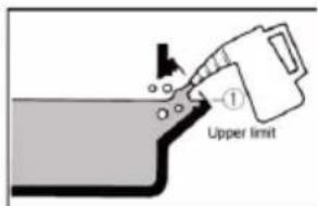
Upper limit Obergrenze
natural_image
Black industrial electrical equipment with control panel and buttons (no visible text or symbols)
natural_image
Close-up of a mechanical device with ports and connectors (no visible text or symbols)natural_image
Technical illustration of an internal combustion engine assembly (no text or labels visible)11.4 Luftfilter
natural_image
Mechanical assembly diagram showing a belt buckle securing a component (no text or symbols)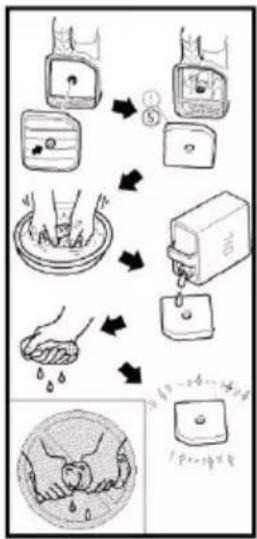
flowchart
graph TD
    A["Water washing"] --> B["Water washing step ①"]
    B --> C["Water washing step ⑤"]
    C --> D["Water washing step ⑥"]
    D --> E["Water washing step ⑦"]
    E --> F["Water washing step ⑧"]
    F --> G["Water washing step ⑨"]
    G --> H["Water washing step ⑩"]
natural_image
Illustration of a pipe with a funnel pouring liquid into a container (no text or symbols)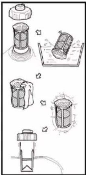
WARNING (WARNUNG)
flowchart
graph TD
    A["GENERATOR BLOCK"] --> B["Controller Panel Block"]
    B --> C["Generator Block"]
    C --> D["Engine Block"]
    D --> E["Control Panel Block"]

    subgraph Control Panel Block
        F["Cr"] --> G["Blue"]
        H["B"] --> I["Brown"]
        J["Cy"] --> K["Green/Yellow"]
        L["V"] --> M["White"]
        N["R"] --> O["Red/White"]
        P["R/W"] --> Q["Red/White"]
        R["Y"] --> S["Y"]
        T["Yellow"] --> U["Gray"]
    end

    subgraph Inverter Block
        V["CR"] --> W["0.25 mm² G/V"]
        X["B"] --> Y["-"]
        Z["R"] --> AA["+"]
        AB["DEC"] --> AC["DC recapture"]
        AD["ESC switch"] --> AE["overload imdicator lighter"]
        AF["Gy 230V 696A"] --> AG["AC recapture"]
    end

    subgraph Engine Block
        AH["option coil charging"] --> AI["drain sensor"]
        AJ[" ignition coil charging"] --> AK["R/V"]
        AL[" spark plug"] --> AM["B"]
        AN[" stepper motor speed"] --> AO["B"]
        AP[" ignition"] --> AQ["B"]
    end

    style Control Panel Block fill:#f9f,stroke:#333
    style Inverter Block fill:#ccf,stroke:#333
    style Engine Block fill:#cfc,stroke:#333
    style Generator Block fill:#fcc,stroke:#333
LOW POWER GENERATOR SET
| Rated Power: 1700 W | IP-Class: IP23M |
| Max. Power: 1880 W | Power Factor: 1.0 |
| Rated Voltage: 230 V/AC | Quality Class: A |
| Frequency: 50 Hz | Performance Class: G1 |
| Rated Current: 7.39 A | Operating temp.: -5....+40 °C |
| Net Weight: 21.5 kg | ISO 8528-13: 2016 |

Model-No.: QL2000i
Year of Production: 2022
Serial No.: XXXXXXXXXX
distributed by Conrad Electronic SE Klaus-Conrad-Str. 1 D-92240 Hirschau www.toolcraft.net
License Holder/Manufacturer: Taizhou Qinglong Machinery & Electric Co., Ltd., Mazhuang Village, Jiazhi Street, Jiaojiang District, Taizhou, Zhejiang, 318012 P.R. China


www.tuv.com ID 1111255473
3 Safety Instructions 31
4 Latest product information ....31
5 Safety information....32
6 Intended use 34
7 Product overview 36
7.1 Control panel 37
8 Control functions 38
8.1 Engine switch....38
8.2 Oil warning light (yellow)....38
8.3 Overload indicator (red) 38
8.4 AC indicator (green)....38
8.5 DC overload protection 38
8.6 Economy control switch (ECS) 39
8.7 Tank cap 39
8.8 Tank cap bleed valve 39
8.9 Ground terminal (earth) 39
9 Before operation 39
9.1 Fuel....39
9.2 Engine oil 40
10 Operation....41
10.1 Starting the engine 42
10.2 Switching off the engine....43
10.3 AC power connection....43
10.4 Charging the battery 44
10.5 Area of application 45
11 Maintenance 46
11.1 Inspecting the spark plug 47
11.2 Carburettor setting 48
11.3 Changing the engine oil 48
11.4 Air filter 49
11.5 Exhaust silencer shielding and spark arrester 49
11.6 Fuel tank filter 50
11.7 Fuel filter 50
12 Storage/Transport....51
12.1 Draining the fuel 51
12.2 Engine....52
13 Troubleshooting....52
13.1 The engine does not start....52
13.2 The generator does not generate power 52
14 Specifications....53
15 Wiring configuration....54
16 Cleaning....56
17 Disposal....56
17.1 Product 56
18 Nameplate 57
19 Declaration of Conformity (DOC)....57
2 Introduction
Dear customer,
Thank you for purchasing this petrol-driven generator with a built-in inverter.
This manual contains instructions on how to operate this machine. Read it carefully before getting started. Safe and correct operation can help you to achieve optimal performance. All information in this guide is based on the latest product information available at the time of printing. The content in this guide may differ from the actual device components due to revisions and other changes.
We reserve the right to make changes at any time without prior notice and without obligation of any kind. No part of this publication may be reproduced without our written permission.
This manual must be considered as an integral part of the generator and must be handed over together with the generator in the event of a resale.
For technical queries, please contact:
www.conrad.com/contact
3 Safety Instructions
The safety of people, as well as property belonging to you and others, is of great importance. Please read these notes carefully, which are accompanied by a preceding symbol ⚠ or NOTICE
DANGER (WARNING) There is a RISK OF DEATH or SERIOUS INJURY if you do not follow the instructions.
WARNING (WARNING) There is a RISK OF DEATH or SERIOUS INJURY if you do not follow the instructions.
CAUTION (CAUTION) You MAY be INJURED if you do not follow the instructions.
NOTICE (IMPORTANT) The generator or other objects could be damaged if you do not follow the instructions.
4 Latest product information
Download the latest product information at www.conrad.com/downloads or scan the QR code shown. Follow the instructions on the website.

5 Safety information
Before using the generator, read and ensure that you fully understand this user manual. Familiarizing yourself with the safe operating procedures of the generator will help to prevent accidents.
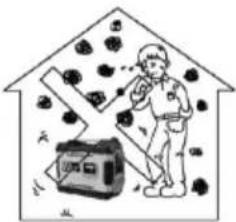 Never use indoors. Never use in damp environments. Never use indoors. Never use in damp environments. | 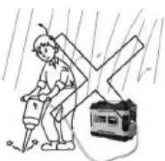 |
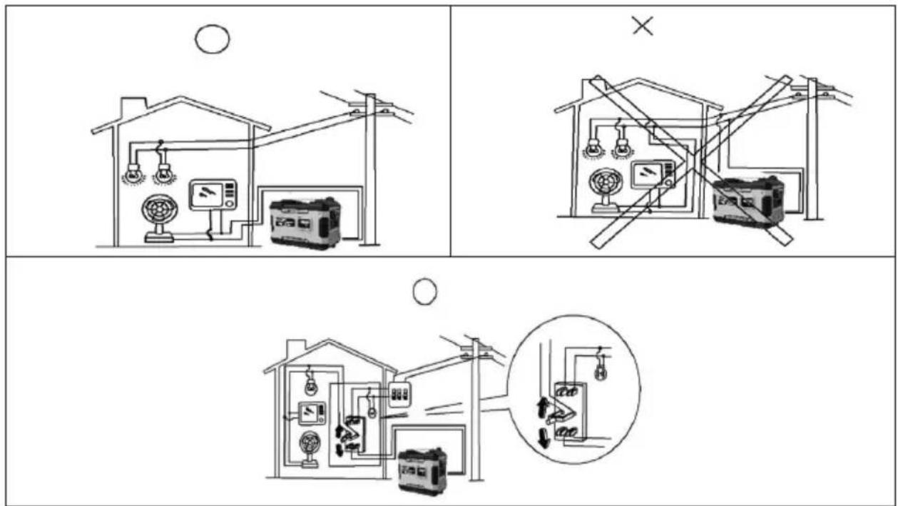
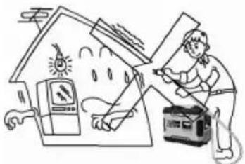 Never connect the generator directly to the domestic power system. Never connect the generator directly to the domestic power system. | |
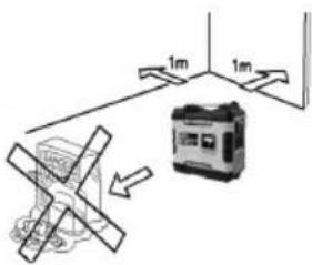 Keep the generator at least 1 metre away from combustible materials. Keep the generator at least 1 metre away from combustible materials. | 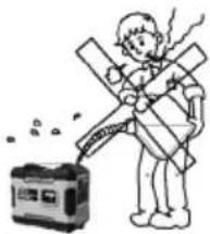 Never smoke when refuelling. Never smoke when refuelling. |
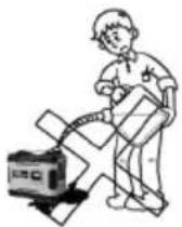 Do not spill petrol when refuelling. Stop the engine before refuelling. Do not spill petrol when refuelling. Stop the engine before refuelling. | 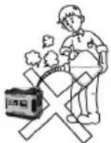 |
 Do not refuel when the generator is in use! Do not refuel when the generator is in use! | |
 | Caution |
 | Read the operating instructions before use |
 | Electrical hazard |
 | Exposure to carbon monoxide (CO) |
 | Fire hazard |
 | Risk of combustion |
 | Wear ear defenders. |
 | All electrical and electronic equipment placed on the European market must be labelled with this symbol. This symbol indicates that this device should be disposed of separately from unsorted municipal waste at the end of its service life. All owners of waste equipment are obliged to dispose of waste equipment separately from unsorted municipal waste.Before handing the old device to a collection point, end users are required to separate old batteries which are not enclosed by the old device, as well as lamps which can be removed from the old device without any damage.Distributors of electrical and electronic equipment are legally required to accept waste equipment free of charge. Conrad provides the following return options free of charge (more details on our website):At our Conrad storesAt the collection points established by ConradAt the collection points of public waste disposal agencies or at the collection systems set up by manufacturers and distributors in accordance with the German Electrical and Electronic Equipment Act.The end user is responsible for deleting personal data on the old device before disposal.Please note that in countries outside Germany, other obligations may apply to the return and recycling of old devices. |
| [26K8] | Meets the relevant safety standards of European directives |
- Protection against electric shock depends on the circuit breakers, which must be precisely tailored to the power generation unit. If a circuit breaker needs to be replaced, it must be replaced by a circuit breaker with the same rating and performance characteristics.
- If extension lines or mobile networks are used, the resistance value must not exceed 1.5 . As a reference, the total length of cables for a cross-section of 1.5 mm^2 should not exceed 60 m; for a cross-section of 2.5 mm^2 , the total length should not exceed 100 m.
6 Intended use
The generator is designed to generate electricity and can be used with the rated output power under normal atmospheric conditions.
Improper use:
Never use indoors. Never use in damp environments. The use of leaded petrol will cause serious damage to internal engine parts.
Residual risk:
Any improper connection may damage the generator or cause a fire.
No connection to a domestic power supply:
Installation and major repairs should only be carried out by specially trained personnel.
Please dispose of used engine oil in an environmentally friendly manner. We recommend that you take it to your local collection point for recycling in a sealed container. Do not dispose of it in the dustbin or pour it onto the ground.
The use of personal protective equipment such as gloves, ear plugs etc. is recommended. Generator sets can only be used in accordance with the rated power and the specified ambient conditions. If they are used under conditions that do not comply with the prescribed conditions and the cooling of the engine or generator is impaired (e.g. as a result of use in undesignated areas), the current output must be reduced. Information should be provided to inform the user of the required reduction in output due to use at higher temperatures, altitudes and/or humidity than the values specified in the prescribed conditions.
The generator must not be connected to other power supplies, such as the power supply of energy supply companies.
As a result of high mechanical loads, only durable rubber insulated cables (in accordance with IEC 60245-4) or an equivalent material should be used.
Power generation units may only be used up to their rated power under the rated environmental conditions. If the power generation unit is used under conditions which do not comply with the reference conditions according to ISO 8528-8, 7.1 (ambient temperature of 25^ , ambient pressure of 100kPa , and relative humidity of 30% ), the power must be reduced.
– Ambient temperature: -5\~40°C
– Humidity: Below 50% at 40°C.
– Altitude: Less than 1000 m.
NOTICE (NOTE)
If the generator is connected to a domestic mains supply as a back-up system, the connection must be completed by an electrician or another qualified person.
When the loads are connected to the generator, check carefully to ensure that the electrical connections are safe and reliable. Any improper connection may damage the generator or cause a fire.
Grounding of the generator
To avoid electric shock from poor quality electrical equipment or improper use of the power supply, the generator must be grounded with a well insulated electrical conductor.
NOTICE (NOTE)
Ensure that the control panel, ventilation slots and inverters are well cooled and that no objects, dirt or water can enter. The engine, converter, or alternator may be damaged if the cooling fan is blocked.
When moving, storing or running the unit, do not allow the generator to come into contact with other parts. The generator may be damaged or cause damage to property in the event of a leak.
7 Product overview
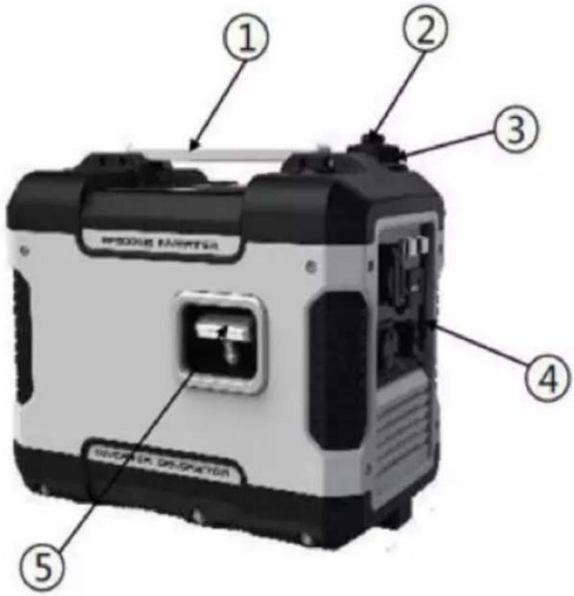
- Carry handle
- Tank cap bleed valve
- Tank cap
- Control panel
- Pull starter
- Oil cap
- Ventilation slot
- Exhaust silencer
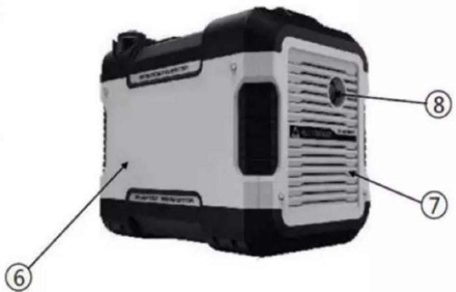
7.1 Control panel
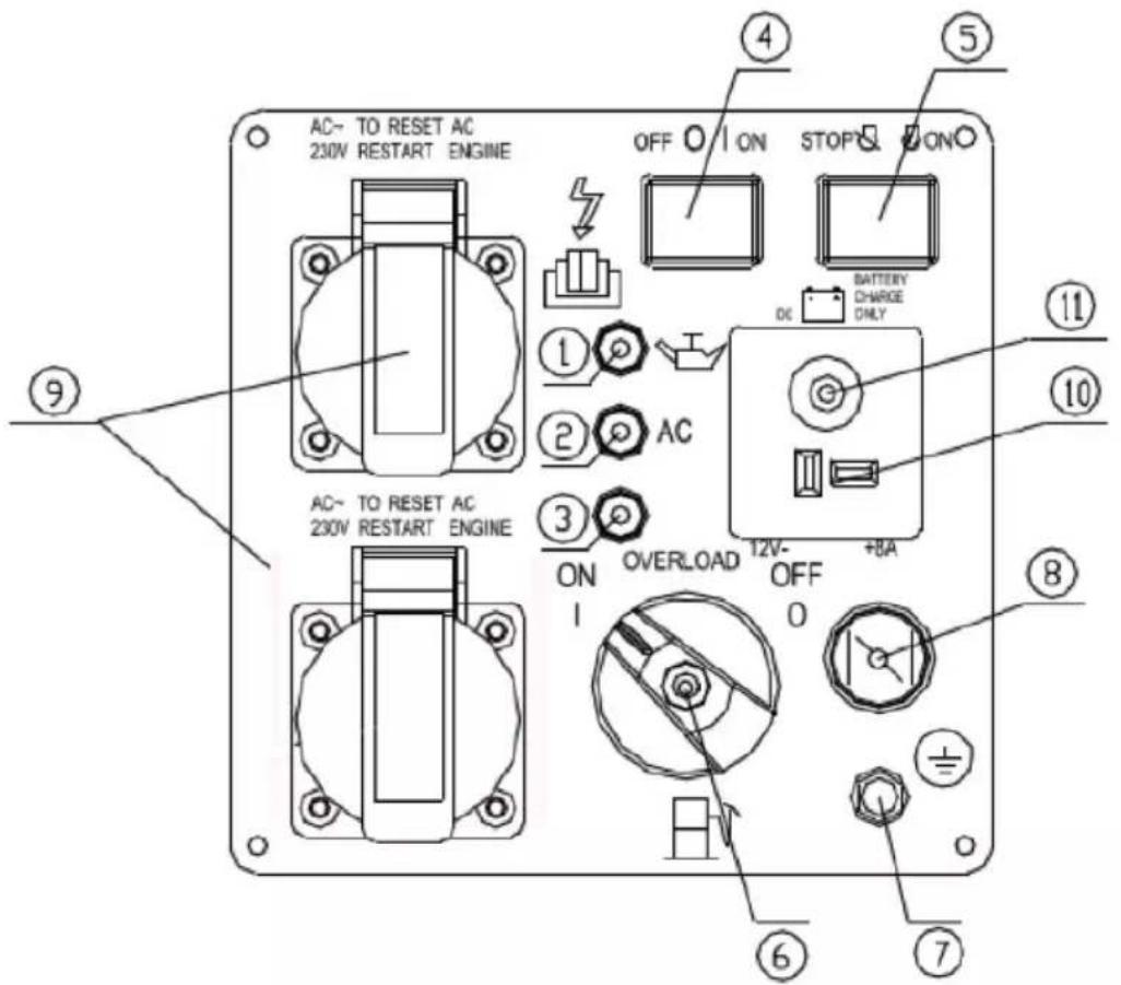
- Oil warning light
- AC indicator
- Overload indicator
- Economy control switch (black)
- Engine switch (red)
- Fuel tap
- Earth terminal (ground)
- Choke
- AC socket
- DC socket
- DC protection function
(1) Engine switch in "STOP" position
The ignition switch is switched off. The engine will not start.
(2) Engine switch in "ON" position
The ignition switch is switched on. The engine can be started.
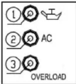
8.2 Oil warning light (yellow)
If the oil level falls below the minimum level, the oil warning light (1) will turn on and the engine will stop automatically. If the engine is not refilled with oil, it will not start.
Tip: If the engine stalls or fails to start, switch the engine switch to "ON" and then pull the pull starter.
If the oil warning light flashes for a few seconds, this indicates that there is insufficient engine oil. Refill the engine with oil, and then restart the engine.
8.3 Overload indicator (red)
The overload indicator (3) lights up when the system detects an overload in a connected electrical device, when the inverter control unit overheats, or when the AC output voltage increases. The AC protection function will then be triggered. Power generation will be stopped to protect the generator and all connected electrical devices. The AC indicator light (green) will switch off and the overload indicator (red) will stay on, but the engine will not stop.
If the overload indicator switches on and power generation stops, do the following:
- Switch off all connected electrical devices and the engine.
- Decrease the total power of the connected devices to reduce the rated output power.
- Check for blockages at the cooling air inlet and the control unit. If any blockages are visible, remove them.
- After checking, restart the engine.
Tips: The overload indicator may light up for a few seconds when you connect electrical devices that require a large inrush current, such as a compressor or submersible pump. This does not indicate a malfunction.
8.4 AC indicator (green)
The AC indicator (2) switches on when the engine is started and power is being generated.
8.5 DC overload protection
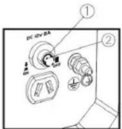
The DC overload protection function automatically switches to "OFF" (2) when an electrical device is connected to the generator and the output current is higher than the rated power. To use this device again, switch on the DC overload protection by setting the knob to "ON" (1).
(1) "ON"
Direct current is generated.
(2) "OFF"
Direct current is not generated.
CAUTION (CAUTION)
As soon as the DC overload protection function is triggered, reduce the current load of the connected electrical device such that it is below the rated output power of the generator. If the DC overload protection function is triggered again, stop using the device immediately and contact an authorized dealer.
8.6 Economy control switch (ECS)
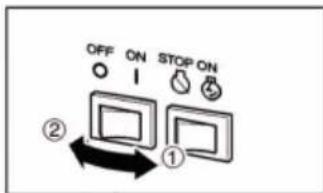
"ON" (1)
When the ECS switch is set to "ON", the economy control unit controls the engine speed according to the connected load. This helps to ensure more efficient fuel consumption and less noise.
"OFF" (2)
When the ECS switch is set to "OFF", the engine will run at the rated speed (4500 r/min), regardless of whether a load is connected.
Tip:
The ECS must be set to "OFF" when connecting electrical devices that require a high inrush current, such as a compressor or submersible pump.
8.7 Tank cap
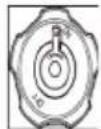
Remove the tank cap by turning it anticlockwise.
8.8 Tank cap bleed valve
The tank cap (2) is fitted with a bleed valve (1) to stop the flow of fuel. The bleed valve must be set to "ON". This will allow the fuel to flow into the carburettor and start the engine. If the engine is not in use, turn the bleed valve to "OFF" to stop the flow of fuel.
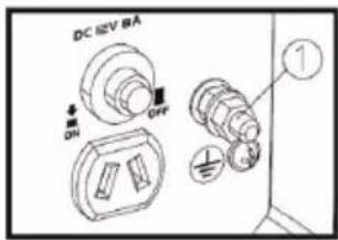
8.9 Ground terminal (earth)
The ground terminal (1) is connected to the ground cable to prevent an electric shock. If the electrical device is grounded, the generator must always be grounded.
9 Before operation
9.1 Fuel
DANGER (WARNING)
Fuel is highly flammable and toxic.
Carefully check the "SAFETY INFORMATION" before filling the tank with fuel.
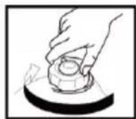
Do not overfill the fuel tank, otherwise the fuel may overflow as it heats up and expands.
After filling the fuel tank, make sure that the tank cap is tight.
NOTICE (IMPORTANT)
Immediately wipe any spilled fuel with a clean, dry and soft cloth, as fuel can damage painted surfaces or plastic parts.
- Only use unleaded petrol. The use of leaded petrol will cause serious damage to internal engine parts.
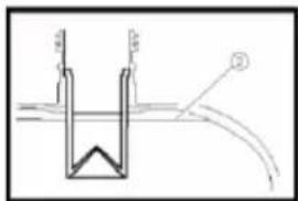
Remove the tank cap and fill the fuel tank to the red mark.
(1) Red mark
(2) Fuel height
Recommended fuel: Unleaded petrol
Tank capacity: Total 4.0 L (1.06 US gal, 0.88 Imp gal)
9.2 Engine oil
NOTICE (IMPORTANT)
The generator is supplied without engine oil. Do not start the engine until sufficient engine oil has been added.
Recommended engine oil: SAE 10W 30
Engine oil quantity: 0.35 L
-
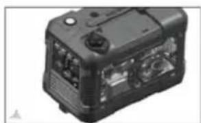
Place the generator on a level surface.
-
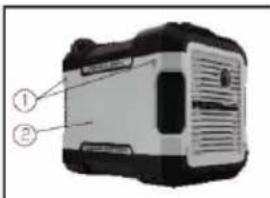
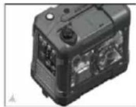
Remove the screws (1), and then remove the cover (2).
-
Remove the oil cap.
-
Add the specified amount of recommended engine oil, and then replace and tighten the oil cap.
natural_image
Black industrial electronic device with visible internal components and mounting points (no text or symbols)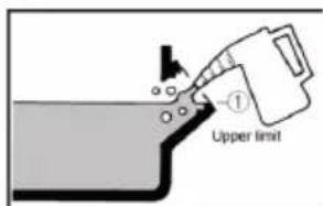
| Upper limit Obergrenze |
- Replace the cover and tighten the screws.
Pre-start check
WARNING (WARNING)
If any element does not function properly during the pre-start check, ask a technician to check and repair it before starting the generator.
The condition of the generator is the responsibility of the owner. Important components can deteriorate quickly and unexpectedly, even when the generator is not in use.
TIP: Pre-start checks should be carried out before each use.
Pre-start checks:
Fuel (see page 39)
Check that there is enough fuel in the tank.
If necessary, refill the tank.
Engine oil (see page 40)
Check that there is enough engine oil.
If necessary, add the specified amount of recommended oil.
Check for oil leaks from the generator.
If an anomaly is detected during use
Check whether the generator is operating correctly.
If necessary, add the specified amount of recommended oil.
If necessary, contact a specialist.
10 Operation
WARNING (WARNING)
Never operate the engine in a closed room, as this can quickly lead to unconsciousness and death. Operate the engine in a well-ventilated place.
Do not connect any electrical devices before starting the engine.
NOTICE (IMPORTANT)
The generator is supplied without engine oil. Do not start the engine until the sufficient amount of engine oil has been added.
Do not tilt the generator when adding the engine oil. This could result in overfilling and cause damage to the engine.
TIP: The generator can be used with the rated output power under standard atmospheric conditions.
"Standard atmospheric conditions":
Ambient temperature: 25 °C
Barometric pressure: 100 kPa
Relative humidity: 30 %
The output power of the generator varies depending on the ambient temperature, altitude (lower air pressure at higher altitudes) and humidity.
The output power of the generator will drop if the temperature, humidity and altitude are higher than the standard atmospheric conditions.
In addition, the current load must be reduced if the generator is used in a narrow space, as this affects the cooling of the generator.
10.1 Starting the engine
-
Turn the ECS switch (black) to "OFF" (1).
-
Turn the bleed valve to "ON" (2).
-
Turn the fuel tap to "ON".
-
Switch the machine switch (red) to "ON".
-
Fully remove the choke.
TIP: The choke is not necessary when starting a warm engine.
Push the choke back into its original position.
- Pull slowly on the pull starter until it engages with the gear at the other end, then pull quickly on the lead.
TIP: Hold the carry handle firmly to prevent the generator from falling over when operating the pull starter.
- After the engine starts, warm the engine until it does not stop when you reset the choke lever to its original position.

TIP: If the ECS switch is set to "ON" when the engine is started, there is no load on the generator:
If the ambient temperature is below 0^ C ( 32^ F), the engine must be left running for approx. 5 minutes at the indicated speed (4500 rpm) in order to warm up.
At an ambient temperature below 5^ C ( 41^ F), the engine must be left running for approx. 3 minutes at the indicated number of revolutions (4500 rpm) in order to warm up.
The ECS unit is normally switched on after the aforementioned period (during which ECS is "OFF") has elapsed.
10.2 Switching off the engine
TIP: Switch off all electrical devices.
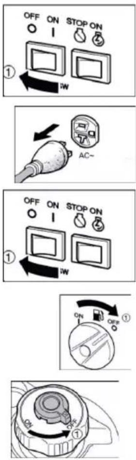
- Switch the ECS to "OFF" (1).
- Disconnect all electrical devices.
- Set the engine switch (red) to "STOP".
- Turn the fuel tap to "OFF" (1).
- Turn the bleed valve to "OFF" (1) after the engine has cooled down completely.
10.3 AC power connection
WARNING (WARNING)
Make sure that all electrical devices are switched off before plugging them in.
NOTICE (IMPORTANT)
Before connecting to the generator, make sure that all electrical devices, including the cables and plug connections, are in good condition.
Make sure that the total load is within the rated output power of the generator.
Make sure that the current load of the socket is within the range of the socket's rated load.
TIP: Ensure that you ground the generator (ground terminal). If the electrical device is grounded, the generator must always be grounded..
- Start the engine.
- Switch ECS to "ON".
- Connect the device to the AC socket.
- Check that the AC indicator is switched on.
- Switch on all connected devices.
TIP: The ECS must be set to "OFF" to increase the engine speed to the default rated speed. If you need to connect multiple loads or power consuming devices to the generator, connect the device with the highest inrush current first, and the device with the lowest inrush current last.
10.4 Charging the battery
TIP:
■The alternator has a DC voltage rating of 12 V.
- Start the engine, and then connect the battery to the generator for charging.
Before charging the battery, make sure that the DC overload protection is switched on.
- Start the engine.
- Connect the red battery charger cable to the positive (+) battery terminal.
- Connect the black battery charger cable to the negative (-) battery terminal.
- Switch the ECS to "OFF" to start charging the battery.
NOTICE (IMPORTANT)
■ Make sure that the ECS is turned off during the charging process.
- Ensure that you connect the red battery charger cable to the positive (+) battery terminal and the black cable to the negative (-) battery terminal. Do not reverse these positions.
- Firmly connect the battery charging cables to the battery terminals to ensure that they will not be disconnected by engine vibrations or other disturbances.
Charge the battery using the correct procedure as described in the battery instruction manual.
The DC overload protection function is triggered automatically when the current rises above the specified values while the battery is charging. To restart the charging process, switch the DC overload protection function to "ON" by pressing the button. If the DC overload protection function is triggered again, stop charging the battery immediately and contact a specialist.
TIP:
■ Follow the instructions in the battery manual to determine the charging time.
Measure the density of the electrolyte to determine if the battery is fully charged. At full charge, the specific gravity of the electrolyte should be between 1.26 and 1.28.
It is advisable to check the density of the electrolyte at least once an hour to prevent the battery from overcharging.
WARNING (WARNING)
Do not smoke or connect/disconnect devices to/from the battery during the charging process. This may cause sparks, which can ignite the battery gas.
Battery electrolytes are toxic and dangerous. The battery contains sulphuric acid, which can cause severe burns and other health hazards. Avoid contact with skin, eyes and clothing.
Remedies:
SKIN CONTACT: Rinse with water.
INGESTION: Drink large amounts of water or milk. Then drink milk with magnesium, a beaten egg or vegetable oil. Consult a doctor immediately.
EYE CONTACT: Rinse with water for 15 minutes and seek immediate medical attention.
Batteries generate explosive gases. Keep the battery away from sparks, flames, cigarettes, etc. Ensure that the room is well-ventilated when charging the battery. Always wear eye protection when working near batteries.
KEEP OUT OF REACH OF CHILDREN.
10.5 Area of application
When using the generator, ensure that the total load is within the rated output power of the generator. Failure to do so may cause damage to the generator.
| AC |  |  |  |  |
| Power factor 1 0.8 - 0.95 0.4 - 0.75 | (Efficiency 0.85) | |||
| Rated power ≤ 1700 W ≤ 1360 W ≤ 544 W Nominal volt- | age: 12 V Rated current: 8 A |
TIP:
The wattage of a device indicates the individual power of a device when used.
The simultaneous use of AC and DC current is possible, but the total wattage of the rated power must not be exceeded.
Example:
| Nominal output power of the generator 1700 W | ||
| Frequency Power factor | ||
| 1.0 ≤ 1700 W | ||
| AC 0.8 ≤ 1360 W | ||
| DC --- 96 W (12 V / 8 A) | ||
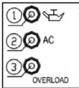
The overload indicator (3) lights up when the total wattage exceeds the generator's range. (See page 10 for more information.)
NOTICE (IMPORTANT)
Do not overload the generator. The total load of all electrical devices/appliances must not exceed the generator's supply range. Overloading will damage the generator.
When connecting precision devices, electronic controls, PCs, computers, microcomputer equipment or battery chargers, keep the generator at a distance to prevent electrical interference with the engine. In addition, make sure that electrical noise from the engine does not interfere with other electrical devices located near the generator.
Before connecting the generator to medical equipment, seek advice from the manufacturer, a doctor or hospital.
Some electrical appliances or universal electric motors have high inrush currents and therefore cannot be used, even if they are within the designated range as indicated in the table above. Contact the device manufacturer for more details.
11 Maintenance
The engine must be properly maintained to ensure safe, economical, trouble-free and environmentally-friendly operation.
In order to keep the petrol-operated engine in optimal condition, it must be serviced at regular intervals. The required maintenance and routine inspections are indicated below, and must be carefully observed:
| Element\Frequency | Every time | After the first month or after 20 hours of use | Thereafter, every 3 months or every 50 hours of use | Every year or every 100 hours of use | |
| Engine oil Check | - Refill | √ | |||
| Replace | √ | √ | |||
| Reduction gear oil (if applicable) | Check oil level | √ | |||
| Replace | √ | √ | |||
| Air filter insert Check | √ | ||||
| Clean | √ | ||||
| Replace | √ | ||||
| Sludge container (if applicable) | Clean | √ | |||
| Spark plug: Check | - Adjust | √* | |||
| Spark arrester Clean | √ | ||||
| Idle mode (if applicable)** | Check - Adjust | √ | |||
| Safety distance value** | Check - Adjust | √ | |||
| Fuel tank & fuel filter | Clean | √ | |||
| Fuel level Check Every 2 years (replacement is necessary) | |||||
| Cylinder head, position C clean carbon deposits** | <225 ccm = every 125 hours≤225 ccm = every 250 hours | ||||
| *These elements should be replaced if replacement is necessary.**Installation and major repairs should be done by a specialist | |||||
NOTICE (IMPORTANT)
If the petrol engine is frequently used at high temperatures or under a heavy load, change the oil every 25 hours.
If the engine is frequently used in dusty or other adverse conditions, clean the air filter every 10 hours. If necessary, replace the air filter every 25 hours.
Maintenance should be conducted at the specified intervals (time period or number of hours of use, whichever is earlier).
If you miss the planned maintenance time, perform the maintenance as soon as possible.
WARNING (WARNING)
Stop the engine before starting any maintenance work. Place the engine on a level surface and remove the spark plug cap to prevent the engine from starting. Do not operate the engine in a poorly ventilated room or in other closed areas. Ensure that the work area is well-ventilated. The engine exhaust gases contain toxic carbon monoxide, the inhalation of which can cause shock or loss of consciousness, and even lead to death.
11.1 Inspecting the spark plug
The spark plug is an important engine component that should be checked at regular intervals.
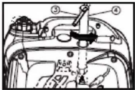
- Remove the cap (1) and the spark plug cap (2), and then insert the tool (4) from the outside of the cover through the hole.
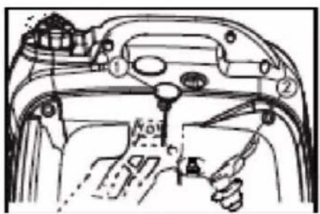
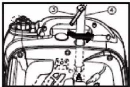
-
Insert the handle (3) into the tool (4) and turn it counter-clockwise to replace the spark plug.
-
Check for discolouration and remove carbon deposits. The porcelain insulator around the central electrode of the spark plug should have a medium to light brown colour.
-
Check the type of spark plug and the gap between the electrodes.
Standard spark plug: A7RTC
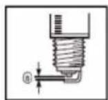
Electrode gap: 0.6 - 0.7 mm (0.024 - 0.028 in)
TIP: The electrode gap should be measured with a feeler gauge and adjusted to the specifications if necessary.
- Install the spark plug.
Spark plug connector torque: 20.0 N * m (2.0 kgf * m, 14.8 lbf * ft)
TIP: If a torque wrench is not available when installing the spark plug, a good estimate of the correct torque is an additional 1/4 - 1/2 turn after you achieve a finger-tight fit when screwing in the spark plug. However, the spark plug should be tightened to the specified torque as soon as possible.
- Install the spark plug cap and the spark plug cover.
11.2 Carburettor setting
WARNING (WARNING)
The carburettor is an important part of the engine. Adjustments should be made by authorized distributors who have the requisite expertise, specialized tools and equipment.
11.3 Changing the engine oil
Avoid draining the engine oil immediately after stopping the engine. The oil is hot and should be handled with care to avoid burn injuries.
Recommended engine oil: SAE 10W 30
Recommended engine oil type: API service SE type or higher
Engine oil quantity: 0.35 L
-
Place the generator on a level surface and warm up the engine for a few minutes. Stop the engine and turn the 3-in-1 switch knob, tank cap and bleed valve to "OFF".
-
Remove the screws (1), followed by the cover (2).
-
Remove the oil cap (3).
-
Place an oil sump under the engine. Tilt the generator to drain the oil completely.
-
Place the generator back on the level surface.
NOTICE (IMPORTANT)
Do not tilt the generator when filling the engine oil. This could lead to overfilling and cause damage to the engine.
-
Fill engine oil to the upper mark.
-
Wipe the cover clean and wipe up any spilled oil.
NOTICE (IMPORTANT)
Make sure that no foreign bodies enter the crankcase.
-
Reinstall the oil cap.
-
Install the cover and tighten the screws.
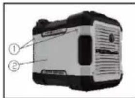
natural_image
Black industrial electronic device with ports and mounting holes (no visible text or symbols)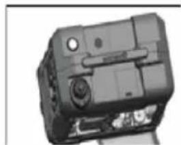
natural_image
Close-up of a black electronic device with ports and buttons (no visible text or symbols)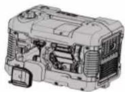
natural_image
Technical illustration of an internal combustion engine assembly (no text or labels visible)11.4 Air filter
-
Remove the screws (1), followed by the cover (2).
-
Remove the screw (3), and then remove the air filter on the housing cover (4).
-
Remove the foam element (5).
-
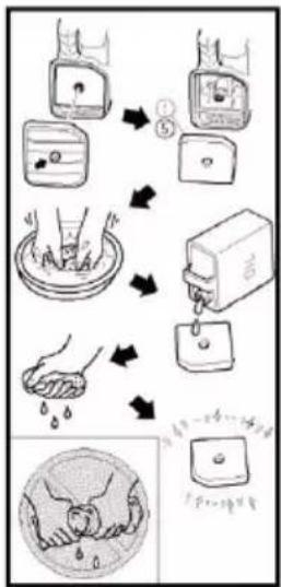
Wash the foam element in solvent and dry it.
-
Oil the foam element and squeeze out any excess oil.
The foam element should be moist, but not dripping with oil.
NOTICE (IMPORTANT)
Do not wring the foam element when squeezing out the oil, as this may cause it to tear.
- Insert the foam element into the air filter housing.
TIP: Make sure that the sealing surface of the foam element is flush with the air filter so that there are no air leaks. The engine should never be operated without the foam element, otherwise piston and cylinder wear may occur.
-
Install the air filter cover in its original position and tighten the screw.
-
Replace the cover and tighten the screws.
11.5 Exhaust silencer shielding and spark arrester
WARNING (WARNING)
flowchart
graph TD
    A["Water Level"] --> B["Water Depth"]
    B --> C["Water Depth"]
    C --> D["Water Depth"]
    D --> E["Water Depth"]
    E --> F["Water Depth"]
    F --> G["Water Depth"]
    G --> H["Water Depth"]
    H --> I["Water Depth"]
    I --> J["Water Depth"]
    J --> K["Water Depth"]
    K --> L["Water Depth"]
    L --> M["Water Depth"]
    M --> N["Water Depth"]
    N --> O["Water Depth"]
    O --> P["Water Depth"]
    P --> Q["Water Depth"]
    Q --> R["Water Depth"]
    R --> S["Water Depth"]
The engine and silencer will be very hot after the engine has been running. Avoid touching the hot engine and silencer with any part of the body or clothing during inspection or repair work.
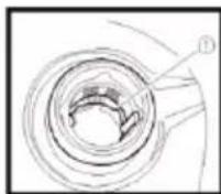
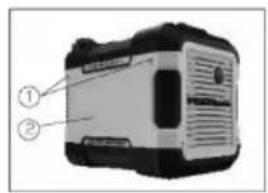
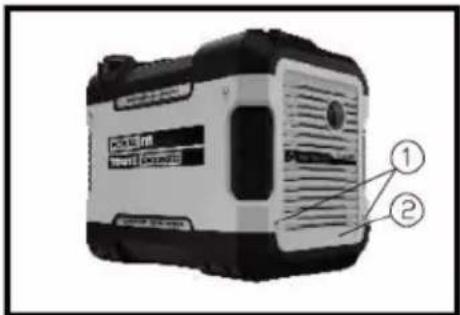
- Remove the screws (1), and then remove the indicated parts of the cover (2).
natural_image
Line drawing of a car interior showing a belt buckle and seatbelt (no text or symbols)-
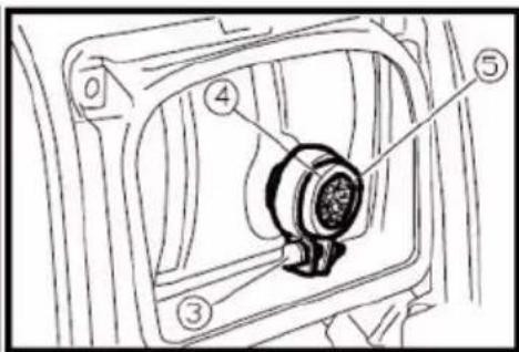
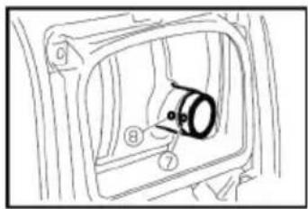
Remove the screw (3), and then remove the silencer cap (4), the silencer shield (5), and the spark arrester (6).
-
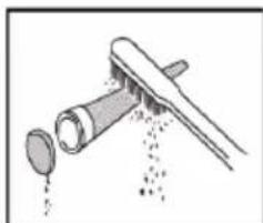
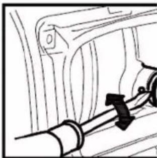
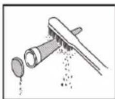
Clean the carbon deposits on the silencer shield and spark arrester with a wire brush.
NOTICE (IMPORTANT)
When cleaning, use the wire brush gently to avoid damaging or scratching the silencer shield and spark arrester.
natural_image
Illustration of a pipe nozzle with liquid dripping through it (no text or symbols)- Inspect the silencer shield and spark arrester.
Replace if damaged.
- Install the spark arrester.
TIP: Align the protruding part of the spark arrester (7) with the hole in the silencer pipe.
- Install the silencer shield and silencer cap.
- Replace the cover and tighten the screws.
11.6 Fuel tank filter
WARNING (WARNING)
Never smoke or approach an open flame while you are handling fuel.
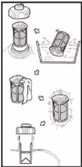
- Remove the tank cap and the filter.
- Clean the filter with petrol.
- Allow the filter to dry and reinstall it.
- Reinstall the tank cap. Make sure that the tank cap is screwed tight.
11.7 Fuel filter
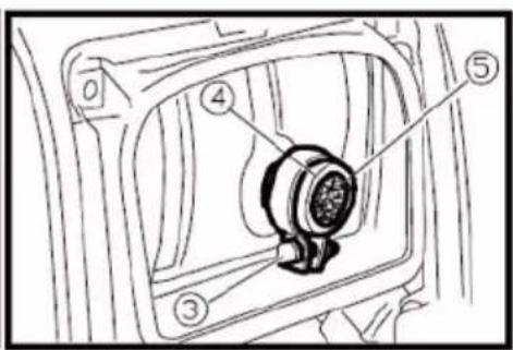
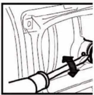
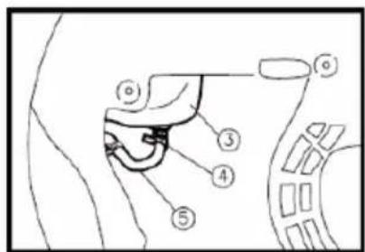
- Remove the screws (1), and then remove the cover (2) and allow the fuel (3) to drain.
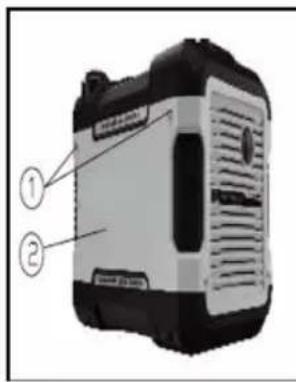
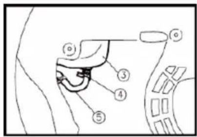
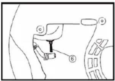
- Hold and pull the clamp (4) upwards, and then remove the hose (5) from the tank.
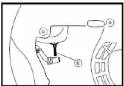
- Remove the fuel filter (6).
- Clean the filter with petrol.
- Dry the filter and put it back into the tank.
- Install the hose and clamp, and then open the fuel valve to check for leaks.
- Install the cover and tighten the screws.
12 Storage/Transport
To prevent fuel spillage during transport or storage, the generator should be placed upright in its normal operating position with the engine switched off. Allow the engine to cool down before moving the tank lid bleed valve to the OFF position.
When transporting the generator:
- Do not overfill the tank (there must be no fuel in the filler neck).
- Do not operate or store the generator inside a vehicle. Remove the generator from the vehicle and use it in a well-ventilated place.
- Avoid direct sunlight when leaving the generator inside a vehicle. If the generator is left in a closed vehicle for many hours, high temperature inside the vehicle could vaporise fuel, resulting in a possible explosion.
- Do not drive on unpaved roads for an extended period of time when the generator is on board. If you need to transport the generator on unpaved roads, drain the fuel tank first.
If the generator is stored for an extended period, preventive measures must be taken to prevent deterioration and corrosion. The storage temperature should be between -25°C to 55°C.
12.1 Draining the fuel
- Move the engine switch to "STOP" (1).
- Remove the tank cap and the filter. Extract the fuel from the tank into an approved fuel canister. Then replace the tank cap.
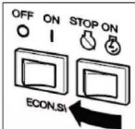
WARNING (WARNING)
Petrol is highly flammable and toxic. Check the "SAFETY INFORMATION" carefully (see page 32).
NOTICE (IMPORTANT)
Immediately wipe off any spilled fuel with a clean, dry, and soft cloth, as fuel can damage painted surfaces or plastic parts.
- Start the engine (see page 14) and let it run until it stops. The engine will stop approximately 20 minutes after the fuel runs out.
TIP:
Do not connect any electrical devices (no load).
The time for which the engine runs depends on the amount of fuel remaining in the tank.
-
Remove the screws, followed by the cover.
-
Drain the fuel from the carburettor by loosening the drain plug on the carburettor's float chamber.
-
Switch the engine to "STOP".
-
Tighten the drain plug.
-
Replace the cover and tighten the screws.
-
Turn the bleed valve to "OFF" after the engine has cooled down completely.
12.2 Engine
Follow these steps to protect the cylinder, piston rings, etc. from corrosion.
- Remove the spark plug, pour approximately one tablespoon of SAE 10W 30 oil into the hole of the spark plug, and then reinstall the spark plug. Perform an incomplete engine start-up with the pull starter by making repeated incomplete pulls (set to "OFF" with the 3-in-1 switch knob) to coat the cylinder walls with oil.
- Pull the pull starter until you feel resistance, and then stop pulling (this prevents the cylinders and valves from rusting).
- Clean the generator housing. Store the generator in a dry, well-ventilated place with the cover over it.
13 Troubleshooting
13.1 The engine does not start
1. Fuel systems
Fuel is not being fed into the combustion chambers.
- There is no fuel in the tank... Add fuel to the tank.
"May be performed by a layman." - There is fuel in the tank... The tank cap bleed valve and the fuel tap are set to "ON"
– Dirty fuel filter... Clean the fuel filter.
"May be performed by a layman."
– Clogged carburettor.... Clean the carburettor.
"Installation and major repairs must only be carried out by trained personnel."
2. Insufficient engine oil
The engine oil level is low... Add engine oil.
"May be performed by a layman."
3. Electrical systems
Set the 3-in-1 switch to "CHOKE" and pull the pull starter... Poor spark formation. The spark plug is wet or contaminated with carbon... Remove the carbon deposits or rub the spark plug dry.
"May be performed by a layman."
Faulty ignition system... contact a specialist.
"Installation and major repairs must only be carried out by trained personnel."
13.2 The generator does not generate power
- Safety mechanism (DC overload protection function) is set to "OFF"... Set the DC overload protection function to "ON".
- The AC indicator light (green) is off... Stop and restart the engine.
14 Specifications
| Element 2 KW generator | ||
| Generator | Type QL2000i | |
| Nominal frequency (Hz) 50 | ||
| Nominal voltage (V) 230 AC | ||
| Nominal output power (kW) 1.7 | ||
| Max. output power (kW) 1.88 | ||
| Power factor 1.0 | ||
| Charging voltage (DC) (V) 12 | ||
| Charging current (DC) (A) 8 | ||
| Overload protection (DC) Safety mechanism (no fuse) | ||
| Phase Simple | ||
| Engine Engine QL80 | ||
| Engine type Single cylinder, 4-stroke, forced air cooling, overhead valves | ||
| Displacement (cm3) 79.7 | ||
| Fuel type Unleaded petrol | ||
| Tank capacity (L) | 4 | |
| Fuel consumption (g/kW) ≤ 450 | ||
| Operating time (at rated power) (hrs) | 4 | |
| Oil capacity (L) 0.35 | ||
| Recommended engine oil | SAE 10W 30 | |
| Model no. Spark plug: | A7RTC | |
| Start method | Pull starter | |
| Generator dimensions | Length × Width × Height (mm) | 486 x 295 x 429 |
| Net weight (kg) 21.5 | ||
Noise level: 92 dB. / Uncertainty of the noise test: 2 dB
15 Wiring configuration
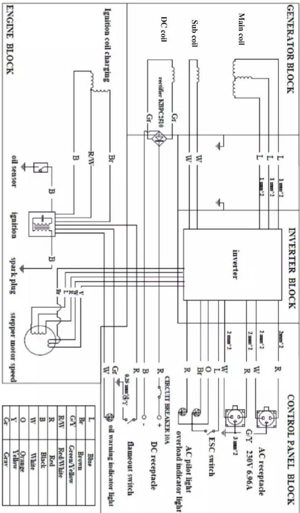
flowchart
graph TD
    A["GENERATOR BLOCK"] --> B["Controller Panel Block"]
    B --> C["Generator Block"]
    C --> D["Engine Block"]
    D --> E["Control Panel Block"]

    subgraph Control Panel Block
        F["Cr"] --> G["Blue"]
        H["B"] --> I["Brown"]
        J["Cy"] --> K["Green/Yellow"]
        L["V"] --> M["White"]
        N["R"] --> O["Red/White"]
        P["R/W"] --> Q["Red/White"]
        R["Y"] --> S["Y"]
        T["Yellow"] --> U["Gray"]
    end

    subgraph Inverter Block
        V["CR"] --> W["0.25 mm² G/V"]
        X["B"] --> Y["-"]
        Z["R"] --> AA["+"]
        AB["DEC"] --> AC["DC recapture"]
        AD["ESC switch"] --> AE["overload imdicator lighter"]
        AF["Gy 230V 696A"] --> AG["AC recapture"]
    end

    subgraph Engine Block
        AH["option coil charging"] --> AI["drain sensor"]
        AJ[" ignition coil charging"] --> AK["R/V"]
        AL[" spark plug"] --> AM["B"]
        AN[" stepper motor speed"] --> AO["B"]
        AP[" ignition"] --> AQ["B"]
    end

    style Control Panel Block fill:#f9f,stroke:#333
    style Inverter Block fill:#ccf,stroke:#333
    style Engine Block fill:#cfc,stroke:#333
    style Generator Block fill:#fcc,stroke:#333
- Do not use any aggressive cleaning agents, rubbing alcohol or other chemical solutions. These may damage the housing and can cause the product to malfunction.
-
Do not immerse the product in water.
-
Disconnect the product from all connected devices.
- Clean the product with a dry, lint-free cloth.
17 Disposal
17.1 Product
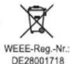
All electrical and electronic equipment placed on the European market must be labelled with this symbol. This symbol indicates that this device should be disposed of separately from unsorted municipal waste at the end of its service life.
All owners of waste equipment are obliged to dispose of waste equipment separately from unsorted municipal waste. Before handing the old device to a collection point, end users are required to separate old batteries which are not enclosed by the old device, as well as lamps which can be removed from the old device without any damage.
Distributors of electrical and electronic equipment are legally required to accept waste equipment free of charge. Conrad offers the following free return options (further information is available on our website):
At our Conrad stores
At the collection points established by Conrad
At the collection points of public waste disposal agencies or at the collection systems set up by manufacturers and distributors in accordance with the German Electrical and Electronic Equipment Act.
The end user is responsible for deleting personal data on the old device before disposal.
Please note that in countries outside Germany, other obligations may apply to the return and recycling of old devices.
18 Nameplate

TOOLCRAFT
LOW POWER GENERATOR SET
| Rated Power: 1700 W | IP-Class: IP23M |
| Max. Power: 1880 W | Power Factor: 1.0 |
| Rated Voltage: 230 V/AC | Quality Class: A |
| Frequency: 50 Hz | Performance Class: G1 |
| Rated Current: 7.39 A | Operating temp.: -5....+40 °C |
| Net Weight: 21.5 kg | ISO 8528-13: 2016 |

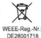
Model-No.: QL2000i
Year of Production: 2022
Serial No.: XXXXXXXXXX
distributed by Conrad Electronic SE Klaus-Conrad-Str. 1 D-92240 Hirschau www.toolcraft.net
License Holder/Manufacturer: Taizhou Qinglong Machinery & Electric Co., Ltd., Mazhuang Village, Jiazhi Street, Jiaojiang District, Taizhou, Zhejiang, 318012 P.R. China


www.tuv.com ID 1111255473
19 Declaration of Conformity (DOC)
Conrad Electronic SE, Klaus-Conrad-Straße 1, D-92240 Hirschau, hereby declares that this product conforms to the following directives:
EMC directive 2014/30/EU
EN 61000-6-1:2019
EN 55012:2007+A1
MD Directive 2006/42/EG
EN ISO 8528-13:2016
AFPs GS 2019:01
Regulation (EU) 2016/1628
Issue: E24*2016/1628*2016/1628SHB2/P*0029*00
Directive 2000/14/EC + 2005/88/EC
EN ISO 3744:1995
ISO 8528-10:1998
RoHS Directive 2011/65/EU + 2015/863/EU
Click on the following link to read the full text of the EU declaration of conformity: www.conrad.com/downloads
Enter the product item number in the search box. You can then download the EU declaration of conformity in the available languages.


- NOTICE (HINWEIS)
- CAUTION (VORSICHT)
- Motoröl
- Luftfilter
- WARNING (WARNUNG)
- Introduction
- Safety Instructions
- Latest product information
- Safety information
- Intended use
- Improper use:
- Residual risk:
- NOTICE (NOTE)
- Grounding of the generator
- Product overview
- Control panel
- Oil warning light (yellow)
- Overload indicator (red)
- AC indicator (green)
- DC overload protection
- CAUTION (CAUTION)
- Economy control switch (ECS)
- "ON" (1)
- "OFF" (2)
- Tank cap
- Tank cap bleed valve
- Ground terminal (earth)
- Before operation
- Fuel
- DANGER (WARNING)
- NOTICE (IMPORTANT)
- Engine oil
- Pre-start check
- WARNING (WARNING)
- Pre-start checks:
- Fuel (see page 39)
- Engine oil (see page 40)
- If an anomaly is detected during use
- Operation
- "Standard atmospheric conditions":
- Starting the engine
- Switching off the engine
- AC power connection
- Charging the battery
- TIP:
- Remedies:
- Area of application
- Maintenance
- Inspecting the spark plug
- Carburettor setting
- Changing the engine oil
- Air filter
- Exhaust silencer shielding and spark arrester
- Fuel tank filter
- Fuel filter
- Storage/Transport
- When transporting the generator:
- Draining the fuel
- Engine
- Troubleshooting
- The engine does not start
- Fuel systems
- Insufficient engine oil
- Electrical systems
- The generator does not generate power
- Wiring configuration
- Disposal
- Product
- Nameplate
- Declaration of Conformity (DOC)
Brand : Toolcraft
Model : QL2000i
Category : Generator