
IQ System Interface II - Professional audio interface CROWN - Free user manual and instructions
Find the device manual for free IQ System Interface II CROWN in PDF.


| Product Type | Interface between host computer and Crown Bus loops |
| Brand | Crown |
| Model | IQ-INT II (IQ System Interface II) |
| Dimensions (H x W x D) | 1.75 in (4.4 cm) x 19 in (48.3 cm) x 6.5 in (16.5 cm) |
| Weight | 6 lb 4 oz (2.91 kg) |
| Power Requirements | 100–120 VAC or 220–240 VAC, 50–60 Hz |
| Power Consumption | 8.0–11.6 W depending on line voltage |
| Number of Crown Bus Loops Supported | 8 |
| Crown Bus Data Rate | 38.4 kbaud (20 mA current loop) |
| Crown Bus Connectors | Input: 5-pin female DIN; Output: 4-pin female DIN (8 pairs) |
| Host Computer Connector | Female 9-pin D-sub (RS232/RS422/RS423) |
| Supported Host Baud Rates | 300, 600, 1200, 2400, 4800, 9600, 19200, 38400 |
| Maximum RS232 Distance | 50 ft (15.2 m) |
| Maximum RS422 Distance | 2,000 ft (610 m) |
| Maximum Crown Bus Distance | Variable: up to 3,000 ft (914 m) with low‑capacitance wire |
| Front Panel Indicator | Enable LED (power on) |
| Internal Controls | 8‑segment DIP switch for communication parameters |
| Chassis Finish | Black powder‑coated steel |
| Mounting | 19-inch standard rack mount (EIA RS‑310‑B) |
| Protection Features | Auto‑reset, optically isolated 20 mA loop receivers |
| Warranty | 3 years full warranty |
| Cleaning Instructions | Clean only with a dry cloth |
| Safety Precautions | Do not expose to rain or moisture; unplug during lightning storms |
| Service | Refer all servicing to qualified personnel; no user‑serviceable parts inside |
Frequently Asked Questions - IQ System Interface II CROWN
User questions about IQ System Interface II CROWN
0 question about this device. Answer the ones you know or ask your own.
Ask a new question about this device
Download the instructions for your Professional audio interface in PDF format for free! Find your manual IQ System Interface II - CROWN and take your electronic device back in hand. On this page are published all the documents necessary for the use of your device. IQ System Interface II by CROWN.
USER MANUAL IQ System Interface II CROWN
REFERENCE MANUAL

An IQ System® to Host Computer Interface
©1999 by Crown International, Inc., P.O. Box 1000, Elkhart, Indiana 46515-1000 U.S.A. Telephone: 219-294-8000. The IQ-INT II is produced by the Professional Audio Unit of Crown International, Inc. Trademark Notice: PIP^TM is a trademark and Crown ^ Amcrom ^ and IQ System ^ are registered trademarks of Crown International, Inc. Other trademarks are the property of their respective owners.

Printed on
recycled paper.
101937-3
9/99

THREE YEAR FULL WARRANTY

WORLDWIDE
NORTH AMERICA
SUMMARY OF WARRANTY
The Crown Audio Division of Crown International, Inc., 1718 West Mishawaka Road, Elkhart, Indiana 46517-4095 U.S.A. warrants to you, the ORIGINAL PURCHASER and ANY SUBSEQUENT OWNER of each NEW Crown ^1 product, for a period of three (3) years from the date of purchase by the original purchaser (the "warranty period") that the new Crown product is free of defects in materials and workmanship, and we further warrant the new Crown product regardless of the reason for failure, except as excluded in this Crown Warranty.
^1 Note: If your unit bears the name “Amcron,” please substitute it for the name “Crown” in this warranty.
ITEMS EXCLUDED FROM THIS CROWN WARRANTY
This Crown Warranty is in effect only for failure of a new Crown product which occurred within the Warranty Period. It does not cover any product which has been damaged because of any intentional misuse, accident, negligence, or loss which is covered under any of your insurance contracts. This Crown Warranty also does not extend to the new Crown product if the serial number has been defaced, altered, or removed.
WHAT THE WARRANTOR WILL DO
We will remedy any defect, regardless of the reason for failure (except as excluded), by repair, replacement, or refund. We may not elect refund unless you agree, or unless we are unable to provide replacement, and repair is not practical or cannot be timely made. If a refund is elected, then you must make the defective or malfunctioning product available to us free and clear of all liens or other encumbrances. The refund will be equal to the actual purchase price, not including interest, insurance, closing costs, and other finance charges less a reasonable depreciation on the product from the date of original purchase. Warranty work can only be performed at our authorized service centers. We will remedy the defect and ship the product from the service center within a reasonable time after receipt of the defective product at our authorized service center.
HOW TO OBTAIN WARRANTY SERVICE
You must notify us of your need for warranty service not later than ninety (90) days after expiration of the warranty period. All components must be shipped in a factory pack. Corrective action will be taken within a reasonable time of the date of receipt of the defective product by our authorized service center. If the repairs made by our authorized service center are not satisfactory, notify our authorized service center immediately.
DISCLAIMER OF CONSEQUENTIAL AND INCIDENTAL
DAMAGES
YOU ARE NOT ENTITLED TO RECOVER FROM US ANY INCIDENTAL DAMAGES RESULTING FROM ANY DEFECT IN THE NEW CROWN PRODUCT. THIS INCLUDES ANY DAMAGE TO ANOTHER PRODUCT OR PRODUCTS RESULTING FROM SUCH A DEFECT.
WARRANTY ALTERATIONS
No person has the authority to enlarge, amend, or modify this Crown Warranty. This Crown Warranty is not extended by the length of time which you are deprived of the use of the new Crown product. Repairs and replacement parts provided under the terms of this Crown Warranty shall carry only the unexpired portion of this Crown Warranty.
DESIGN CHANGES
We reserve the right to change the design of any product from time to time without notice and with no obligation to make corresponding changes in products previously manufactured.
LEGAL REMEDIES OF PURCHASER
No action to enforce this Crown Warranty shall be commenced later than ninety (90) days after expiration of the warranty period.
THIS STATEMENT OF WARRANTY SUPERSEDES ANY OTHERS CONTAINED IN THIS MANUAL FOR CROWN PRODUCTS.
9/90
SUMMARY OF WARRANTY
The Crown Audio Division of Crown International, Inc., 1718 West Mishawaka Road, Elkhart, Indiana 46517-4095 U.S.A. warrants to you, the ORIGINAL PURCHASER and ANY SUBSEQUENT OWNER of each NEW Crown product, for a period of three (3) years from the date of purchase by the original purchaser (the "warranty period") that the new Crown product is free of defects in materials and workmanship. We further warrant the new Crown product regardless of the reason for failure, except as excluded in this Warranty.
ITEMS EXCLUDED FROM THIS CROWN WARRANTY
This Crown Warranty is in effect only for failure of a new Crown product which occurred within the Warranty Period. It does not cover any product which has been damaged because of any intentional misuse, accident, negligence, or loss which is covered under any of your insurance contracts. This Crown Warranty also does not extend to the new Crown product if the serial number has been defaced, altered, or removed.
WHAT THE WARRANTOR WILL DO
We will remedy any defect, regardless of the reason for failure (except as excluded), by repair, replacement, or refund. We may not elect refund unless you agree, or unless we are unable to provide replacement, and repair is not practical or cannot be timely made. If a refund is elected, then you must make the defective or malfunctioning product available to us free and clear of all liens or other encumbrances. The refund will be equal to the actual purchase price, not including interest, insurance, closing costs, and other finance charges less a reasonable depreciation on the product from the date of original purchase. Warranty work can only be performed at our authorized service centers or at the factory. We will remedy the defect and ship the product from the service center or our factory within a reasonable time after receipt of the defective product at our authorized service center or our factory. All expenses in remedying the defect, including surface shipping costs in the United States, will be borne by us. (You must bear the expense of shipping the product between any foreign country and the port of entry in the United States and all taxes, duties, and other customs fees for such foreign shipments.)
HOW TO OBTAIN WARRANTY SERVICE
You must notify us of your need for warranty service not later than ninety (90) days after expiration of the warranty period. All components must be shipped in a factory pack, which, if needed, may be obtained from us free of charge. Corrective action will be taken within a reasonable time of the date of receipt of the defective product by us or our authorized service center. If the repairs made by us or our authorized service center are not satisfactory, notify us or our authorized service center immediately.
DISCLAIMER OF CONSEQUENTIAL AND INCIDENTAL DAMAGES
YOU ARE NOT ENTITLED TO RECOVER FROM US ANY INCIDENTAL DAMAGES RESULTING FROM ANY DEFECT IN THE NEW CROWN PRODUCT. THIS INCLUDES ANY DAMAGE TO ANOTHER PRODUCT OR PRODUCTS RESULTING FROM SUCH A DEFECT. SOME STATES DO NOT ALLOW THE EXCLUSION OR LIMITATIONS OF INCIDENTAL OR CONSEQUENTIAL DAMAGES, SO THE ABOVE LIMITATION OR EXCLUSION MAY NOT APPLY TO YOU.
WARRANTY ALTERATIONS
No person has the authority to enlarge, amend, or modify this Crown Warranty. This Crown Warranty is not extended by the length of time which you are deprived of the use of the new Crown product. Repairs and replacement parts provided under the terms of this Crown Warranty shall carry only the unexpired portion of this Crown Warranty.
DESIGN CHANGES
We reserve the right to change the design of any product from time to time without notice and with no obligation to make corresponding changes in products previously manufactured.
LEGAL REMEDIES OF PURCHASER
THIS CROWN WARRANTY GIVES YOU SPECIFIC LEGAL RIGHTS, YOU MAY ALSO HAVE OTHER RIGHTS WHICH VARY FROM STATE TO STATE. No action to enforce this Crown Warranty shall be commenced later than ninety (90) days after expiration of the warranty period.
THIS STATEMENT OF WARRANTY SUPERSEDES ANY OTHERS CONTAINED IN THIS MANUAL FOR CROWN PRODUCTS.
9/90
The information furnished in this manual does not include all of the details of design, production, or variations of the equipment. Nor does it cover every possible situation which may arise during installation, operation or maintenance. If you need special assistance beyond the scope of this manual, please contact our Technical Support Group.
Crown Audio Division Technical Support Group
Plant 2 SW, 1718 W. Mishawaka Rd., Elkhart, Indiana 46517 U.S.A.
Phone: 800-342-6939 (North America, Puerto Rico and Virgin Islands) or 219-294-8200
Fax: 219-294-8301 Fax Back (North America only): 800-294-4094 or 219-293-9200
Fax Back (International): 219-294-8100 Internet: http://www.crownaudio.com

WARNING
TO REDUCE THE RISK OF ELECTRIC SHOCK, DO NOT EXPOSE THIS EQUIPMENT TO RAIN OR MOISTURE!
PLEASE NOTE
The following universal symbols may appear on your product and/or in various sections of this manual. Wherever they appear, they are to be interpreted as follows:

Lightning Bolt Symbol:
This symbol is used to alert the user to the presence of dangerous voltages and the possible risk of electric shock.

Exclamation Mark Symbol:
This symbol is used to alert the user to refer to the instruction manual for important operating or maintenance instructions.
FCC Class A Compliance
This equipment has been tested and found to comply with the limits for Class A Digital Device, pursuant to Part 15 of the FCC rules. These limits are designed to provide reasonable protection against harmful interference when the equipment is operated in a commercial environment. This equipment generates, uses and can radiate radio frequency energy and, if not installed and used in accordance with the instruction manual, may cause harmful interference to radio communications. Operation of this equipment in a residential area is likely to cause harmful interference in which case the user will be required to correct the interference at his own expense.
The user is cautioned that any changes or modifications not expressly approved by the party responsible for compliance could void the user's authority to operate the equipment.
Note: For a system to comply with FCC rules, all components in the system must be in compliance. Please consult the instruction manuals of all components in an IQ System for FCC compliance.
Important Safety Instructions
1) Read these instructions.
2) Keep these instructions.
3) Heed all warnings.
4) Follow all instructions.
5) Do not use this apparatus near water.
6) Clean only with a dry cloth.
7) Do not block any ventilation openings. Install in accordance with the manufacturer's instructions.
8) Do not install near any heat sources such as radiators, heat registers, stoves, or other apparatus that produce heat.
9) Do not defeat the safety purpose of the polarized or grounding-type plug. A polarized plug has two blades with one wider than the other. A grounding-type plug has two blades and a third grounding prong. The wide blade or the third prong is provided for your safety. If the provided plug does not fit into your outlet, consult an electrician for replacement of the obsolete outlet.
10) Protect the power cord from being walked on or pinched, particularly at plugs, convenience receptacles, and the point where they exit from the apparatus.
11) Only use attachments/accessories specified by the manufacturer.
12) Use only with a cart, stand, bracket, or table specified by the manufacturer, or sold with the apparatus. When a cart is used, use caution when moving the cart/apparatus combination to avoid injury from tip-over.
13) Unplug this apparatus during lightning storms or when unused for long periods of time.
14) Refer all servicing to qualified service personnel. Servicing is required when the apparatus has been damaged in any way, such as power-supply cord or plug is damaged, liquid has been spilled or objects have fallen into the apparatus, the apparatus has been exposed to rain or moisture, does not operate normally, or has been dropped.
CONTENTS
1 Welcomecome 5
1.1 Unpacking 5
2 FacilitiesFacilities 5
3 Installation Installation 6
3.1 Connecting to a Crown Bus Loop 6
3.2 Connecting to a Host Computer 9
3.2.1 Connecting to a Modem 9
3.2.2 Communication Settings 10
4 Technical Information Infor 11
5 Specifications 12
6 Service 13
6.1 Worldwide Service 13
6.2 North American Service 13
6.2.1 Service at a North American Service Center ____ 13
6.2.2 Crown Factory Service 13
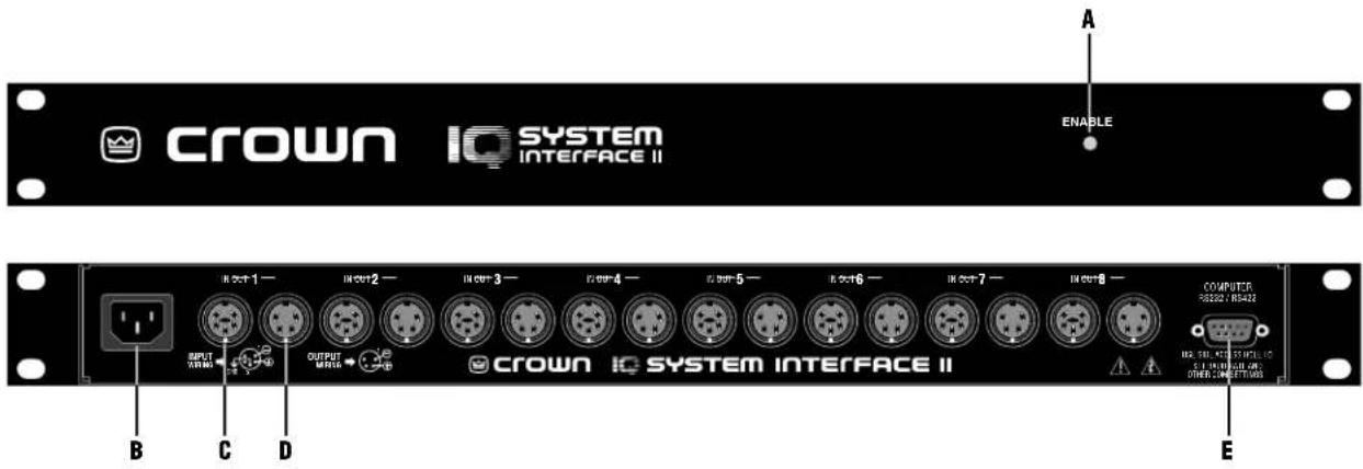
Fig. 1.1 IQ-INT II
1 Welcome
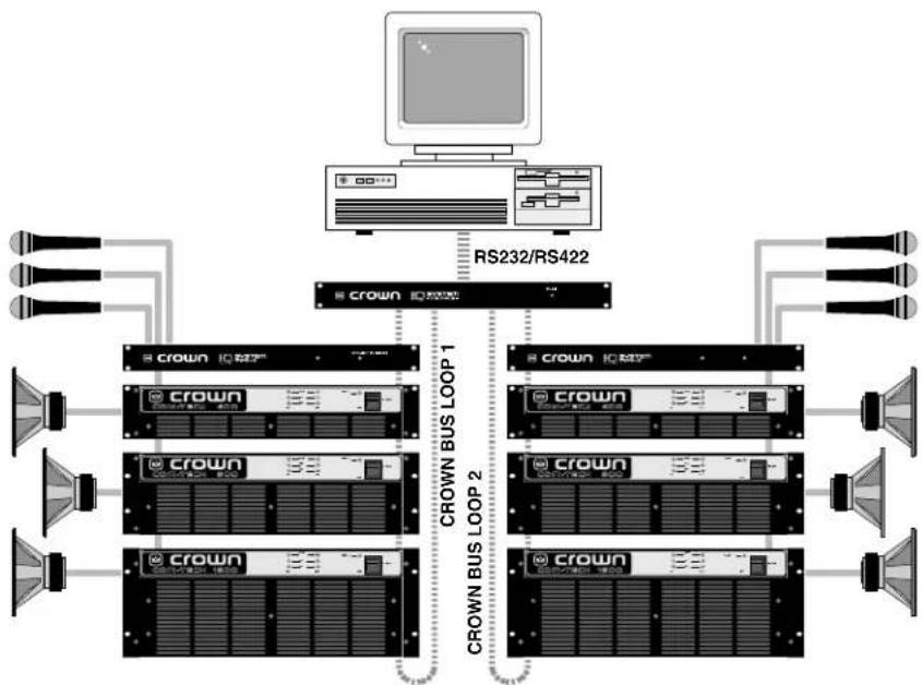
The IQ-INT II is an IQ System interface that connects up to eight different Crown Bus loops to a host computer. It is a self-contained unit with its own Crown Bus drivers, RS232/RS422 drivers and power supply. It has a microprocessor that can be directed by the host computer to execute commands, and it can send and receive commands and data to and from IQ components connected to its Crown Bus loops.
This manual will help you successfully install and use your new interface. Please read all instructions, warnings, and cautions. Also, for your protection, please send in the warranty registration card today and save your bill of sales as it is your official proof of purchase.

1.1 Unpacking
Please unpack and inspect the new interface for any damage that may have occurred during transit. If damage is found, notify the transportation company immediately. Only you, the consignee, may initiate a claim for shipping damage. Crown will be happy to cooperate fully as needed. Save the shipping carton as evidence of damage for the shipper's inspection.
Even if the unit has arrived in perfect condition, as most do, save all packing materials so you will have them if you ever need to transport the unit. NEVER SHIP THE UNIT WITHOUT THE FACTORY PACK.
2 Facilities
A. Enable Indicator
This front panel LED lights when the power cord is connected to the AC mains and the unit is receiving power. The IQ-INT // has no on/off switch.
B. Power Inlet
A standard IEC power inlet. 115-VAC units shipped with Nema® 5-15P power cord. 230-VAC units require a user supplied IEC power cord.
C. Crown Bus Input Connector
A 5-pin female DIN connector is provided for input connection to each of eight separate Crown Bus loops. A mating Switchcraft 502-series connector can be ordered from Crown (part C 7776-5). Pin 1 is negative (-), pin 2 is positive (+), and pin 3 is ground. Pins 4 and 5 are not used. Note: If shielded twisted-pair wire is used for the Crown Bus, the shield should be connected only to pin 3 of the input connector.
D. Crown Bus Output Connector
A 4-pin female DIN connector is provided for output connection to each of eight separate Crown Bus loops. A mating Switchcraft 502 series connector can be ordered from Crown (part C 7777-3). Pin 1 is ground and pin 2 is positive (+). Pins 3 and 4 are not used. Note: If shielded twisted-pair wire is used for the Crown Bus, the shield should not be connected to the output connector.
E. Computer RS232/RS422 Connector
A female, 9-pin D-subminiature connector is provided for serial connection to a host computer. Both RS232 and RS422 communication standards are supported.
flowchart
graph TD
    A["Computer"] --> B["RS232/RS422"]
    B --> C["CROWN BUS LOOP 1"]
    B --> D["CROWN BUS LOOP 2"]
    B --> E["CROWN BUS LOOP 3"]
    B --> F["CROWN BUS LOOP 4"]
    C --> G["CROWN I/O Switch"]
    D --> H["CROWN I/O Switch"]
    E --> I["CROWN I/O Switch"]
    F --> J["CROWN I/O Switch"]
    G --> K["Speaker"]
    H --> L["Speaker"]
    I --> M["Speaker"]
    J --> N["Speaker"]
Fig. 3.1 An IQ System with an IQ-INT II
3 Installation
The installation of an IQ-INT II can be divided into two major parts: Connecting to one or more Crown Bus loops and connecting to the host computer.
3.1 Connecting to a Crown Bus Loop
The Crown Bus is a serial communication loop designed to transmit IQ commands and data. As a communication standard, it is independent of its wiring. This characteristic allows you to wire a Crown Bus loop with either fiber optic cabling or with inexpensive twisted-pair wire, whichever is most appropriate. One IQ System can have more than one Crown Bus loop, and each loop must be unbroken for proper operation.
The IQ-INT II supports up to eight Crown Bus loops. This makes it possible to divide the system into zones, each with its own loop. Using the IQ-INT II to drive multiple Crown Bus loops has several advantages and disadvantages that are listed next.
Multiloop Advantages
- A break in communication in one loop does not affect other loops.
• Over 250 IQ components of the same model can be used in a system. - The same IQ address can be used more than once (once for each type of unit on each loop).
- Larger areas can often be covered without using repeaters or fiber optic cabling.
Single Loop Advantages
- The IQ-INT II can send and receive data slightly faster using a single loop.
- "Real-time" levels can be displayed for a greater number of units.
The IQ-INT II is designed to work with inexpensive twisted-pair wire, so it implements the Crown Bus as a 20-milliamp current loop operating at a baud rate of 38,400. If you want to use fiber optic cabling, contact Crown's Technical Support Group for information on the appropriate transceivers.
Here are some guidelines for twisted-pair wiring:
- A Crown Bus loop must be unbroken to carry commands and data to and from connected units.
- Never cross-connect Crown Bus loops. Each Crown Bus loop is an independent serial communication circuit. A Crown Bus output is connected to the input of the first IQ component on the loop. Each unit's output connects to the next unit's input until the loop returns to the interface where it is connected to the input for the same loop.
- Use twisted-pair wire at least 26 AWG in size. Use twisted-pair wire with a shield when interference is a concern. The wire should be of good quality and should have low capacitance (30 picofarads/foot or less). In most cases, interference is not a problem and unshielded wire is a better choice because of
its lower capacitance. When used with the Crown Bus, a shield serves two purposes: it helps prevent data signals from being transmitted to nearby audio wiring, and helps prevent high external RF levels from interfering with data transmissions. If you must install shielded wire, use a low-capacitance shielded wire like West Penn 452 or equivalent.
- If shielded wire is used, only connect the shield at the input connection. Connecting both ends of the shield may cause a ground loop.
- The total capacitance for each loop should be 40 nanofarads or less. Add up the loop's total capacitance based on the wire's rating in picofarads per foot, and allow approximately 60 picofarads for each connected IQ component. Experience has shown that loops with 75 or more components usually require at least one repeater.
- Add an IQ Repeater for long loops greater than 1,000 feet (305 m) or when required by high-capacitance wire. Although repeaters are recommended for loops longer than 1,000 feet, it is often possible to set up reliable loops of 2,000 feet (610 m) or more without a repeater. Although we recommend shielded wire, unshielded wire typically has less capacitance and can support longer loops.
- Never use the ground wire in a mic snake. At times, it may be convenient to run Crown Bus data signals to and from stage monitor amplifiers along unused wires in a mic snake. If this is done, do not use the ground wire which is normally connected to pin 1 on an XLR connector, or data noise will be added to the audio lines. Use only the signal lines which normally connect to pins 2 and 3 of the XLR's. Note: Because typical mic cables have higher capacitance, the maximum possible Crown Bus loop will be shorter than low-capacitance twisted-pair wire.
Outside RF interference is seldom a problem for a Crown Bus loop—especially if shielded twisted-pair wire is used. However, there are extreme situations when fiber optic wiring is recommended. For example, locating a Crown Bus loop next to an AM radio transmission line may require fiber optic transceivers and cabling. It may also be more practical to use fiber optics for extremely long Crown Bus loops when distances exceed several miles.
Three different of connectors are used for Crown Bus wiring on IQ components. These include DIN connectors, RJ45 connectors, and removable barrier strip plugs. The IQ-INT II uses 5-pin DINs for input and 4-pin DINs for output. Figure 3.2 shows how to connect IQ components with DIN connectors.
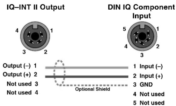
Fig. 3.2 IQ-INT II Output Connection to a DIN Input.
The following examples show how to connect the IQ-INT II to other IQ components on the Crown Bus:

Fig. 3.3 IQ-INT II Output Connection to Barrier Block Input.

Fig. 3.4 Barrier Block IQ Component Connection to an IQ-INT II

Fig. 3.5 IQ-INT II Output Connection to RJ45 Input.

Fig. 3.6 RJ45 Output Connection to a IQ-INT-II.
The IQ components on each Crown Bus loop are connected in succession. Each loop begins and ends with the IQ-INT II. The output of the interface connects to the input of the first unit, then each unit's output is connected to the next unit's input until the loop returns to the interface. This is shown in Figure 3.7.

Fig. 3.7 Crown Bus Wiring from Output to Input.
3.2 Connecting to a Host Computer
There are two main communication standards supported by the IQ-INT II for serial communication with a host computer. They are RS232 and RS422.
RS232 is commonly used with IBM® PCs and compatibles. Because it uses unbalanced signal wiring, it cannot be used for distances over 50 feet (15.2 m).
RS422 uses balanced signal wiring and can be used for distances up to 2,000 feet (610 m) with data grade cable.
Although not very common, RS423 communication can also be used. It is a hybrid of RS232 and RS422 that uses the unbalanced transmitter (TXD) wiring of RS232 and the balanced receiver (RXD) wiring of RS422. It provides signal ground isolation between the transmit and receive lines. With a proper cable, it can be used over a greater distance than RS232, but over a shorter distance than RS422. Contact the Crown Technical Support Group if you want to use RS423 and need more information.
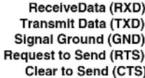
The following illustrations show how to connect the IQ-INT II to the most common host serial ports:
PC (RS232)

Cable connectors are numbered as they appear from the front.
IQ-INT II

Not used
PIN

PIN

Fig. 3.8 Standard RS232 Wiring
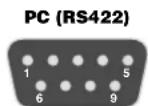
The female interface connector is shown as it appears.

Refer to the documentation provided with your RS422 interface to identify the correct pin connections.
PIN
1 Transmit Data (TXD+)
2 Transmit Data (TXD-)
3 Receive Data (RXD-)
4 Receive Data (RXD+)
5 Signal Ground (GND)
6 Clear to Send (CTS-)
7 Clear to Send (CTS+)
8 Request to Send (RTS+)
9 Request to Send (RTS-)
Fig. 3.9 RS422 Wiring
3.2.1 Connecting to a Modem
The IQ-INT II is also modem compatible. The IQ-INT II periodically sends out an "AT" command string {ATS0=1} that automatically initializes a connected modem to its max baud rate and auto-answer mode. A standard null modem cable should be used between the interface and modem with the exception of pin 4. Pin 4 of the 9- pin RS232/242 connector on the back of the interface should NOT be connected. This pin implements one side of the RS422 type line receiver and, as such, allows balanced wiring on a 9-pin connector. This configuration is not compatible with some 232/null modem applications. Refer to the diagram below for modem wiring detail.
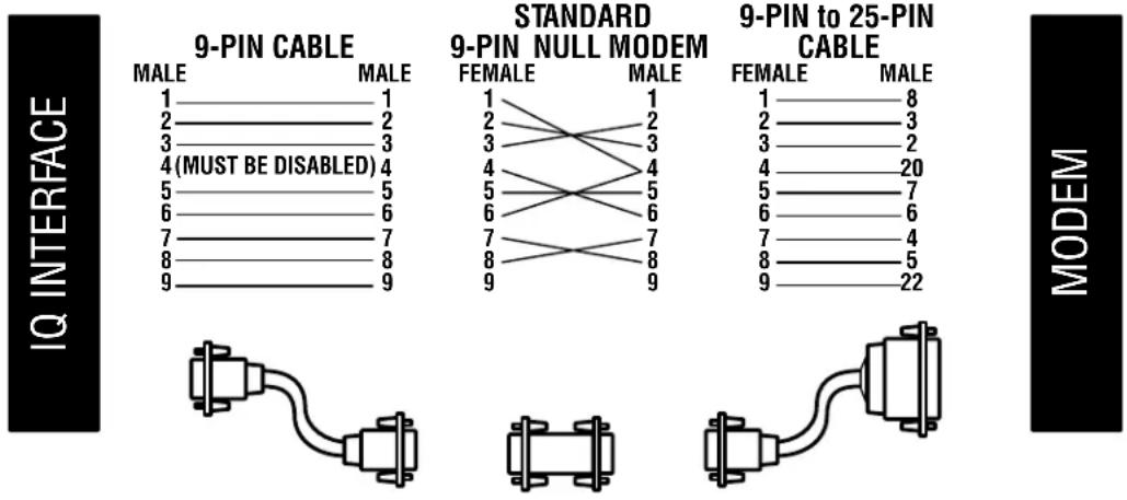
9-PIN to 25-PIN CABLE
Fig. 3.10 Modem Hookup
3.2.2 Communication Settings
Before communication can take place between the unit and a host computer, the communication standard must be selected and the communication parameters must be set with switches accessed through an opening in the side of the chassis (see Figure 3.11).
IMPORTANT: Be sure to disconnect the AC power from the unit before changing the communication standard or parameters.
Setting the communication parameters for RS232 and RS422 serial communication is accomplished using the eight segment DIP switch shown in Figure 3.11. The first five switches set the parity, number of stop bits and data bits. These five switches should ONLY be set in the positions shown in Figure 3.11. The last three switches set the baud rate. Use the fastest baud rate possible.
IMPORTANT: The communication standard and parameters of the IQ-INT II and the host computer must be the same. Any mismatch will prevent communication from taking place.
The communication parameters of the host computer are set using the IQ software. Please refer to your IQ software manual for details.
Here are some important guidelines when configuring serial communication:
- Use these communication parameters for the interface and the host computer: The IQ-INT II should be set at one baud rate below the host
computer (refer to your IQ software manual). Stop bits, data bits and parity checking should be set to their default values.
- The IQ-INT II can be set as high as 38.4 K baud. Use the highest baud rate possible, but be aware that the communication circuitry (UART) in some PC's cannot function over 9600 baud. We strongly recommend using a host computer serial interface with a 16550-compatible UART.
- Do not use twisted-pair wire for RS232 cables because the unbalanced wiring of RS232 is susceptible to crosstalk. Instead use an untwisted cable or ribbon cable. Data grade twisted-pair wire should be used for RS422.
- If the host computer fails to communicate or reports communication errors with the IQ-INT II and the communication standard and parameters are identical, try reducing the baud rate for the interface and the computer. This may be especially useful when configuring for communication via modem.
IMPORTANT: The IQ-INT II should be set at one baud rate slower than the modem is set for accurate communicaton. (Example: 14,400 modem, set the IQ INT II at 9600.)
- If communication problems persist, check the serial cable for improper wiring or possible shorted or broken wires.
- For further assistance, refer to the Troubleshooting section in your IQ System software manual, or contact Crown's Technical Support Group.

Factory-set switch positions are highlighted.
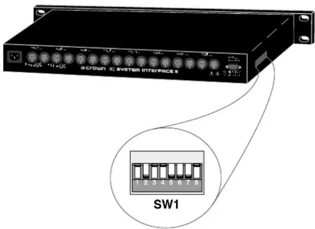
Fig. 3.11 Communication Settings for the IQ-INT II
4 Technical Information
The purpose of the IQ-INT II is to provide a means for the IQ System host computer to communicate with the IQ components. The interface supports RS232, RS422 and RS423 serial data standards. It accepts host computer communication baud rates from 300 to 38,400 and can drive up to 8 independent Crown Bus loops for a high level of fault tolerance. In addition, the IQ-INT II supports both the original IQ System and Ucode protocols, and it provides Crown's own robust network transport layer.
Figure 4.1 shows an IQ-INT II block diagram. The unit has a standard full-wave bridge power supply. Its primary transformer can be configured by an internal voltage select switch for either 115 or 230 VAC; however, this procedure should only be performed by a qualified service technician. (The unit will operate reliably over a wide range of voltages with either AC mains configuration.) A capacitor-coupled half-wave double circuit is used to generate -5 volts.
The interface is equipped with an auto-reset feature. The microprocessor generates an auto-reset signal that can be used as a reliable power-on reset and an automatic "warm" reset in case control is lost due to noise or other anomalies.
The baud rate for communication with the host computer is determined by the baud rate generator which is controlled by an 8-segment DIP switch (SW1). Other serial communication parameters such as data bits, stop bits and parity are also set using SW1.
The interface's microprocessor communicates with other IQ components using its internal UART to drive each loop at 38,400 baud. An external UART is used for communication with the host computer.
Data from the host computer arrives at the serial buffer which accepts RS232, RS422, and RS423 data standards. From here the signal goes to the serial input of the UART which shifts the data from serial to parallel before proceeding to the microprocessor where it is loaded into memory. Next, the interface takes care of any required checksum calculations and other transport layer processing. Finally, all of the data bytes are dumped out the microprocessor's SIO port (the TX pin) at 38,400 baud.
The microprocessor controls the input and output selectors that control which loop will receive data. Data is sent to the selected line driver, which sends the data onto the current loop to the appropriate IQ component.
The line receiver takes incoming data from IQ components and sends it through the input selector to the microprocessor's SIO input RX pin. The microprocessor stores the data in memory and handles the required transport layer processing. The remaining protocol data is then sent to the UART as parallel signals. The UART converts the data from parallel to serial and moves it to the serial output buffer for transmission to the host computer.

flowchart
graph TD
    A["LINE 1 INPUT"] --> B["LINE 1 RECEIVER"]
    C["LINE 2 INPUT"] --> D["LINE 2 RECEIVER"]
    E["LINE 3 INPUT"] --> F["LINE 3 RECEIVER"]
    G["LINE 4 INPUT"] --> H["LINE 4 RECEIVER"]
    I["LINE 1 OUTPUT"] --> J["LINE 1 DRIVER"]
    K["LINE 2 OUTPUT"] --> L["LINE 2 DRIVER"]
    M["LINE 3 OUTPUT"] --> N["LINE 3 DRIVER"]
    O["LINE 4 OUTPUT"] --> P["LINE 4 DRIVER"]
    Q["4 OF 8 LINE DRIVERS"] --> R["SINGLE POLE 8 POSITION SWITCH (ONLY 4 POSITIONS SHOWN)"]
    S["4 OF 8 LINE DRIVERS"] --> T["SINGLE POLE 8 POSITION SWITCH (ONLY 4 POSITIONS SHOWN)"]
    U["SINGLE POLE 8 POSITION SWITCH"] --> V["INTERNAL UART TX"]
    W["SINGLE POLE 8 POSITION SWITCH"] --> X["INTERNAL UART TX"]
    Y["SINGLE POLE 8 POSITION SWITCH"] --> Z["INTERNAL UART TX"]
    AA["SINGLE POLE 8 POSITION SWITCH"] --> AB["INTERNAL UART TX"]
    AC["SINGLE POLE 8 POSITION SWITCH"] --> AD["INTERNAL UART TX"]
    AE["SINGLE POLE 8 POSITION SWITCH"] --> AF["INTERNAL UART TX"]
    AG["SINGLE POLE 8 POSITION SWITCH"] --> AH["INTERNAL UART TX"]
    AI["SINGLE POLE 8 POSITION SWITCH"] --> AJ["INTERNAL UART TX"]
    AK["SINGLE POLE 8 POSITION SWITCH"] --> AL["INTERNAL UART TX"]
    AM["SINGLE POLE 8 POSITION SWITCH"] --> AN["INTERNAL UART TX"]
    AO["SINGLE POLE 8 POSITION SWITCH"] --> AP["INTERNAL UART TX"]
    AQ["SINGLE POLE 8 POSITION SWITCH"] --> AR["INTERNAL UART TX"]
    AS["SINGLE POLE 8 POSITION SWITCH"] --> AT["INTERNAL UART TX"]
    AU["SINGLE POLE 8 POSITION SWITCH"] --> AV["INTERNAL UART TX"]
    AW["SINGLE POLE 8 POSITION SWITCH"] --> AX["INTERNAL UART TX"]
    AY["SINGLE POLE 8 POSITION SWITCH"] --> AZ["INTERNAL UART TX"]
    BA["SINGLE POLE 8 POSITION SWITCH"] --> BB["INTERNAL UART TX"]
    BC["SINGLE POLE 8 POSITION SWITCH"] --> BD["INTERNAL UART TX"]
    BE["SINGLE POLE 8 POSITION SWITCH"] --> BF["INTERNAL UART TX"]
    BG["SINGLE POLE 8 POSITION SWITCH"] --> BH["INTERNAL UART TX"]
    BI["SINGLE POLE 8 POSITION SWITCH"] --> BJ["INTERNAL UART TX"]
    BK["SINGLE POLE 8 POSITION SWITCH"] --> BL["INTERNAL UART TX"]
    BM["SINGLE POLE 8 POSITION SWITCH"] --> BN["INTERNAL UART TX"]
    BO["SINGLE POLE 8 POSITION SWITCH"] --> BP["INTERNAL UART TX"]
    BZ["SINGLE POLE 8 POSITION SWITCH"] --> CA["INTERNAL UART TX"]
    CB["SINGLE POLE 8 POSITION SWITCH"] --> CC["INTERNAL UART TX"]
    CD["SINGLE POLE 8 POSITION SWITCH"] --> CE["INTERNAL UART TX"]
    CF["SINGLE POLE 8 POSITION SWITCH"] --> CG["INTERNAL UART TX"]
    DH["SINGLE POLE 8 POSITION SWITCH"] --> DI["INTERNAL UART TX"]
    DJ["SINGLE POLE 8 POSITION SWITCH"] --> DE["INTERNAL UART TX"]
    DF["SINGLE POLE 8 POSITION SWITCH"] --> DG["INTERNAL UART TX"]
    DHX["SINGLE POLE 8 POSITION SWITCH"] --> DHX["INTERNAL UART TX"]
    BIY["SINGLE POLE 8 POSITION SWITCH"] --> BY["INTERNAL UART TX"]
    BZY["SINGLE POLE 8 POSITION SWITCH"] --> BYX["INTERNAL UART TX"]
    BZX --> BYXX["BAUD RATE GENERATOR"]
    BYX --> BZY
    BZY --> BYX
    BZY --> BYXX["BAUD RATE SWITCH"]
    BYX --> BZY
    BZY --> BYX
    BZYX --> BYX
    BZYX --> BYX
    BZYX --> BYX
    BZYX --> BYX
    BZYX --> BYX
    BZYX --> BYX
    BZYX --> BYX
    BZYX --> BYX
    BZYX --> BYX
Fig. 4.1 IQ-INT II Circuit Block Diagram
5 Specifications
General
Internal Controls: An 8-segment DIP switch is used to configure the data rate and other parameters for communication with the host computer. The switch is accessed through an opening in the side of the chassis.
Connectors: Crown Bus Input: Eight 5-pin female DIN connectors. Crown Bus Output: Eight 4-pin female DIN connectors. (The Crown Bus Input and Output connectors are grouped in pairs to accommodate eight different loops.) Computer: Female 9-pin "D-shell" connector.
Indicators: A front panel enable indicator shows that the unit is plugged in and receiving power.
Power Supply: Standard full-wave bridge power supply with a unique capacitor-coupled half wave doubler circuit to generate -5 VDC.
Power Requirements: 115-V units: 100- to 120-VAC, 50-60 Hz. 230-V units: 220- to 240-VAC, 50-60 Hz.
Power Consumption:
100VAC, 50 Hz: 8.1 W 100VAC, 60 Hz: 8.0 W 120VAC, 50 Hz: 10.6 W 120VAC, 60 Hz: 9.9 W 220VAC, 50 Hz: 10.3 W 220VAC, 60 Hz: 10.0 W 240VAC, 50 Hz: 11.6 W 240VAC, 60 Hz: 11.0 W
Finish: Black powder-coated steel chassis and front panel.
Dimensions: 19-inch (48.3 cm) standard rack mount width (EIA RS-310-B), 1.75-inch (4.4 cm) height and 6.5-inch (16.5 cm) depth.
Weight: 6 lbs., 4 oz. (2.91 kg)
Crown Bus Data Communication
Protection: The auto-reset feature is controlled by the microprocessor. Optically coupled 20-milliamp current loop receivers provide ground isolation.
Data Rate: 38.4 K baud.
Data Format: Asynchronous binary serial data with 1 start bit, 1 stop bit, 8 data bits and no parity check.
Interface Type: 20-milliamp current loop.
Operation: Half duplex.
Intelligence: 8-bit microprocessor.
Transmission Distance: Variable from 200 to 3,000 feet (61 to 914 meters) depending on wire capacitance. 1,000 feet (305 meters) is typical with shielded 26 AWG twisted pair wire. IQ repeaters or fiber optic transceivers can be used to cover greater distances.
Host Computer Data Communication
Data Rate: 300, 600, 1200, 2400, 4800, 9600, 19200, or 38400 baud.
Data Format: Asynchronous binary serial data with 1 start bit, 1 stop bit, 8 data bits and no parity check.
Interface Type: RS232 or RS422.
Operation: Half duplex.
Data Buffer: 64 bytes.
Intelligence: 8-bit microprocessor.
Transmission Distance: RS232: 50 feet (15.2 m). RS422: 2,000 feet (610 m).
6 Service
This unit has very sophisticated circuitry which should only be serviced by a fully trained technician. This is one reason why each unit bears the following label:
CAUTION: To prevent electric shock, do not remove covers. No user serviceable parts inside. Refer servicing to a qualified technician.
6.1 Worldwide Service
Service may be obtained from an authorized service center. (Contact your local Crown/Amcron representative or our office for a list of authorized service centers.) To obtain service, simply present the bill of sale as proof of purchase along with the defective unit to an authorized service center. They will handle the necessary paperwork and repair.
Remember to transport your unit in the original factory pack.
6.2 North American Service
Service may be obtained in one of two ways: from an authorized service center or from the factory. You may choose either. It is important that you have your copy of the bill of sale as your proof of purchase.
6.2.1 Service at a North American Service Center
This method usually saves the most time and effort. Simply present your bill of sale along with the defective unit to an authorized service center to obtain service. They will handle the necessary paperwork and repair. Remember to transport the unit in the original factory pack. A list of authorized service centers in your area can be obtained from our Technical Support Group.
6.2.2 Factory Service
To obtain factory service, fill out the service information page found in the back of this manual and send it along with your proof of purchase and the defective unit to the Crown factory.
For warranty service, we will pay for ground shipping both ways in the United States. Contact Crown Factory Service or Technical Support to obtain prepaid shipping labels prior to sending the unit. Or, if you prefer, you may prepay the cost of shipping, and Crown will reimburse you. Send copies of the shipping receipts to Crown to receive reimbursement.
Your repaired unit will be returned via UPS ground. Please contact us if other arrangements are required.

Always use the original factory pack to transport the unit.
Factory Service Shipping Instructions:
- When sending a Crown product to the factory for service, be sure to fill out the service information form that follows and enclose it inside your unit's shipping pack. Do not send the service information form separately.
- To ensure the safe transportation of your unit to the factory, ship it in an original factory packing container. If you don't have one, call or write Crown's Parts Department. With the exception of polyurethane or wooden crates, any other packing material will not be sufficient to withstand the stress of shipping. Do not use loose, small size packing materials.
- Do not ship the unit in any kind of cabinet (wood or metal). Ignoring this warning may result in extensive damage to the unit and the cabinet. Accessories are not needed—do not send the product documentation, cables and other hardware.
If you have any questions, please call or write the Crown Technical Support Group.
Crown Audio Customer Service
Technical Support / Factory Service Plant 2 SW, 1718 W. Mishawaka Rd., Elkhart, Indiana 46517 U.S.A.
Telephone: 219-294-8200 800-342-6939 (North America, Puerto Rico, and Virgin Islands only)
Facsimile: 219-294-8301 (Technical Support) 219-294-8124 (Factory Service)
Fax Back: 219-293-9200 (North America only) 800-294-4094 (North America only) 219-294-8100 (International)
Internet: http://www.crownaudio.com Email: iqsupport@crownintl.com
Crown Factory Service Information
Shipping Address: Crown International, Inc., Factory Service, Plant 2 SW, 1718 W. Mishawaka Rd., Elkhart, IN 46517
Phone: 1-800-342-6939 or 1-219-294-8200 Fax: 1-219-294-8124
Owner's Name:
Shipping Address:
Phone Number:
Fax Number:
Model:
Serial Number:
Purchase Date:
NATURE OF PROBLEM
(Be sure to describe the conditions that existed when the problem occurred and what attempts were made to correct it.)
Other equipment in your system:
If warranty has expired, payment will be:
□ Cash/Check
□ VISA
MasterCard
□ C.O.D.
Card Number:
Exp. Date:
Signature:
ENCLOSE THIS PORTION WITH THE UNIT. DO NOT MAIL SEPARATELY.
- REFERENCE MANUAL
- THREE YEAR FULL WARRANTY
- WORLDWIDE
- NORTH AMERICA
- SUMMARY OF WARRANTY
- ITEMS EXCLUDED FROM THIS CROWN WARRANTY
- WHAT THE WARRANTOR WILL DO
- HOW TO OBTAIN WARRANTY SERVICE
- DISCLAIMER OF CONSEQUENTIAL AND INCIDENTAL
- DAMAGES
- WARRANTY ALTERATIONS
- DESIGN CHANGES
- LEGAL REMEDIES OF PURCHASER
- THIS STATEMENT OF WARRANTY SUPERSEDES ANY OTHERS CONTAINED IN THIS MANUAL FOR CROWN PRODUCTS.
- DISCLAIMER OF CONSEQUENTIAL AND INCIDENTAL DAMAGES
- Crown Audio Division Technical Support Group
- WARNING
- PLEASE NOTE
- Lightning Bolt Symbol:
- Exclamation Mark Symbol:
- FCC Class A Compliance
- Important Safety Instructions
- CONTENTS
- Welcome
- Unpacking
- Facilities
- Enable Indicator
- Power Inlet
- Crown Bus Input Connector
- Crown Bus Output Connector
- Computer RS232/RS422 Connector
- Installation
- Connecting to a Crown Bus Loop
- Multiloop Advantages
- Connecting to a Host Computer
- Connecting to a Modem
- Communication Settings
- IMPORTANT: Be sure to disconnect the AC power from the unit before changing the communication standard or parameters.
- IMPORTANT: The communication standard and parameters of the IQ-INT II and the host computer must be the same. Any mismatch will prevent communication from taking place.
- IMPORTANT: The IQ-INT II should be set at one baud rate slower than the modem is set for accurate communicaton. (Example: 14,400 modem, set the IQ INT II at 9600.)
- Technical Information
- Specifications
- General
- Power Consumption:
- Crown Bus Data Communication
- Host Computer Data Communication
- Service
- Worldwide Service
- North American Service
- Service at a North American Service Center
- Factory Service
- Factory Service Shipping Instructions:
- Crown Audio Customer Service
- Crown Factory Service Information
- NATURE OF PROBLEM
Brand : CROWN
Model : IQ System Interface II
Category : Professional audio interface