
SH 7 Compact - Unité hydraulique solaire Baxi - Free user manual and instructions
Find the device manual for free SH 7 Compact Baxi in PDF.


| Product Type | Gas-fired combi boiler |
| Model | SH 7 Compact |
| Brand | Baxi |
| Dimensions (H x W x D) | 700 x 400 x 300 mm |
| Weight | 30 kg |
| Power Supply | 230 V / 50 Hz |
| Max Central Heating Output | 24 kW |
| Max Domestic Hot Water Output | 28 kW |
| Energy Efficiency Class | A (ErP) |
| Functions | Central heating, domestic hot water, frost protection, summer/winter mode |
| Ignition | Electronic automatic ignition |
| Safety Features | Overheat protection, flame failure device, pressure relief valve, frost thermostat |
| Maintenance | Annual servicing recommended by qualified engineer |
| Cleaning | Wipe casing with damp cloth; do not use abrasive cleaners |
| Spare Parts | Available from Baxi authorized distributors |
| Repair Index | 7.5 / 10 (estimated) |
| Installation | Must be installed by Gas Safe registered engineer |
| Warranty | 2 years (standard) |
Frequently Asked Questions - SH 7 Compact Baxi
User questions about SH 7 Compact Baxi
0 question about this device. Answer the ones you know or ask your own.
Ask a new question about this device
Download the instructions for your Unité hydraulique solaire in PDF format for free! Find your manual SH 7 Compact - Baxi and take your electronic device back in hand. On this page are published all the documents necessary for the use of your device. SH 7 Compact by Baxi.
USER MANUAL SH 7 Compact Baxi
natural_image
3D rendering of a BAXI air pressure regulator device with gauges and control buttons (no text or symbols on main body)Installation and Service Manual
Pressurised domestic installations
Solar hydraulic unit
SH 7 COMPACT
SH 7 COMPACT TOP
SH 7
SH 14
SH 7 SIMPLE
Dear Customer,
Thank you very much for buying this appliance.
Please read through the manual carefully before using the product, and keep it in a safe place for later reference. In order to ensure continued safe and efficient operation we recommend that the product is serviced regularly. Our service and customer service organisation can assist with this.
We hope you enjoy years of problem-free operation with the product.
1 Safety
1.1 General safety instructions
1.1.1 General safety

Peligro
This appliance can be used by children aged 8 years and above and persons with reduced physical, sensory or mental capabilities or lack of experience and knowledge if they are given correct supervision or instruction on using the appliance in complete safety and understand the hazards involved. Children must not play with the appliance. Cleaning and user maintenance must not be carried out by children without supervision.

Before any work, switch off the power supply to the appliance.

Atención
Use only genuine spare parts.

Importante
Only qualified professionals are permitted to install the appliance, in accordance with prevailing local and national regulations.

Advertencia
Do not touch the pipes. Depending on the settings, the temperature of the pipes may exceed 60 °C.

Advertencia
Take precautions with the domestic hot water. Depending on the settings, the temperature of the domestic hot water may exceed 60 °C .

Advertencia
Only qualified professionals are authorised to work on the appliance and system installation.

Advertencia
Use protective gloves.

Importante
The installation must comply on all points with prevailing regulations and Directives, which govern work and interventions in individual homes, blocks of flats and other buildings.
1.1.2 Electrical safety

Advertencia
If a power supply cable comes with the appliance and it turns out to be damaged, it must be replaced by the manufacturer, its after sales service or persons with similar qualifications in order to obviate any danger.

Importante
The installation must comply on all points with prevailing regulations and Directives, which govern work and interventions in individual homes, blocks of flats and other buildings.

Advertencia
Do not neglect to service the appliance. Contact a qualified professional or take out a maintenance contract for the annual maintenance of the appliance.
1.2 Recommendations

Advertencia
The installation must comply with all the provisions of the regulations (DTU, EN, etc.) governing work and interventions in individual homes, blocks of flats or other buildings.

Importante
Keep the appliance accessible at all times.

Importante
Regularly check that the system is operating correctly.

Importante
Never remove or cover the labels and data plates affixed to appliances. The labels and data plates must be legible throughout the entire service life of the appliance.
Damaged or illegible instructions and warning stickers must be replaced immediately.

Importante
Only remove the casing to perform maintenance and repair work. Put the casing back in place after maintenance and repair work.
1.3 Liabilities
1.3.1 Manufacturer's liability
Our products are manufactured in compliance with the requirements of the various Directives applicable. They are therefore delivered with the C€ marking and any documents necessary. In the interests of the quality of our products, we strive constantly to improve them. We therefore reserve the right to modify the specifications given in this document.
Our liability as manufacturer may not be invoked in the following cases:
- Failure to abide by the instructions on installing and maintaining the appliance.
- Failure to abide by the instructions on using the appliance.
- Faulty or insufficient maintenance of the appliance.
1.3.2 Installer's liability
The installer is responsible for the installation and initial commissioning of the appliance. The installer must observe the following instructions:
- Read and follow the instructions given in the manuals provided with the appliance.
• Install the appliance in compliance with prevailing legislation and standards. - Carry out initial commissioning and any checks necessary.
- Explain the installation to the user.
- If maintenance is necessary, warn the user of the obligation to check the appliance and keep it in good working order.
- Give all the instruction manuals to the user.
1.3.3 User's liability
To guarantee optimum operation of the system, you must abide by the following instructions:
- Read and follow the instructions given in the manuals provided with the appliance.
- Call on a qualified professional to carry out installation and initial commissioning.
- Get your installer to explain your installation to you.
- Have the required inspections and maintenance carried out by a qualified installer.
- Keep the instruction manuals in good condition close to the appliance.
2 About this manual
2.1 General
This manual is intended for installers of pressurised hydraulic units.
2.2 Symbols used
2.2.1 Symbols used in the manual
This manual uses various danger levels to draw attention to special instructions. We do this to improve user safety, to prevent problems and to guarantee correct operation of the appliance.

Peligro
Risk of dangerous situations that may result in serious personal injury.

Risk of electric shock.

Advertencia
Risk of dangerous situations that may result in minor personal injury.

Atención
Risk of material damage.

Importante
Please note: important information.

Consejo
Reference to other manuals or pages in this manual.
3 Technical specifications
3.1 Directives
The pump and solar control supplied with this product comply with the CE marking.
For all provisions and Directives referred to in these instructions, it is agreed that all addenda or subsequent provisions will apply at the time of installation.
3.2 Technical data
Tab.1 Technical data of the hydraulic units
| SH 7 COM- | PACT | SH 7 COM-PACT TOP | SH 7 SH 14 SH 7 | SIMPLE | ||
| Maximum field of collectors | m^2 | 14 14 14 28 14 | ||||
| Nominal flow rate l/ | h · m^2 | 30 30 30 30 30 | ||||
| Supply voltage V 1~230/50 Hz 1 | ~230/50 Hz 1~230/50 Hz | 1~230/50 Hz 1~230/50 Hz | ||||
| Electrical power consumption W | 46 46 | 45 60 45 | ||||
| Maximum current A 16 3 16 16 | 16 | |||||
| Protection rating IP 20 20 20 20 | 20 | |||||
3.3 Dimensions and connections
Fig.1 Dimensions and connections SH 7 Compact / SH 7 Compact Top
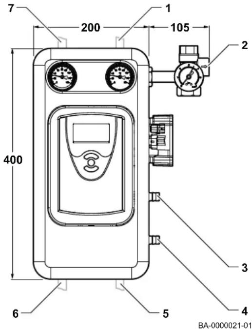
3.3.1 SH 7 Compact / SH 7 Compact Top
Tab.2 Connections SH 7 Compact / SH 7 Compact Top
| Connection | Size | |
| 1 | Flow pipe to solar installation (lower connection of solar panels) | Dia. 22 |
| 2 | Safety valve outlet | G3/4" H |
| 3 | Filling the system | G3/4" M |
| 4 | Draining the system | G3/4" M |
| 5 | Tank outlet | Dia. 22 |
| 6 | Tank inlet | Dia. 22 |
| 7 | System return (upper connection of solar panels) | Dia. 22 |
Fig.2 Dimensions and connections SH 7 and SH 14

3.3.2 SH 7, SH 14
Tab.3 Connections SH 7 and SH 14
| Connection Size | ||
| 1 Flow | pipe to solar installation (lower connection of solar panels) | Dia. 22 |
| 2 Safety valve outlet G3/4" H | ||
| 3 Filling the system G3/4" M | ||
| 4 Draining the system G3/4" M | ||
| 5 Tank outlet Dia. 22 | ||
| 6 Tank inlet Dia. 22 | ||
| 7 System return (upper connection of solar panels) Dia. 22 | ||
Fig.3 Dimensions and connections SH 7 Simple

3.3.3 SH 7 Simple
Tab.4 Connections SH 7 Simple
| Connection Size | ||
| 1 Flow | pipe to solar installation (lower connection of solar panels) | Dia. 22 |
| 2 Safety | valve outlet G3/4" H | |
| 3 Filling | the system G3/4" M | |
| 4 Draining | the system G3/4" M | |
| 5 Tank | outlet Dia. 22 | |
3.4 Electrical diagram
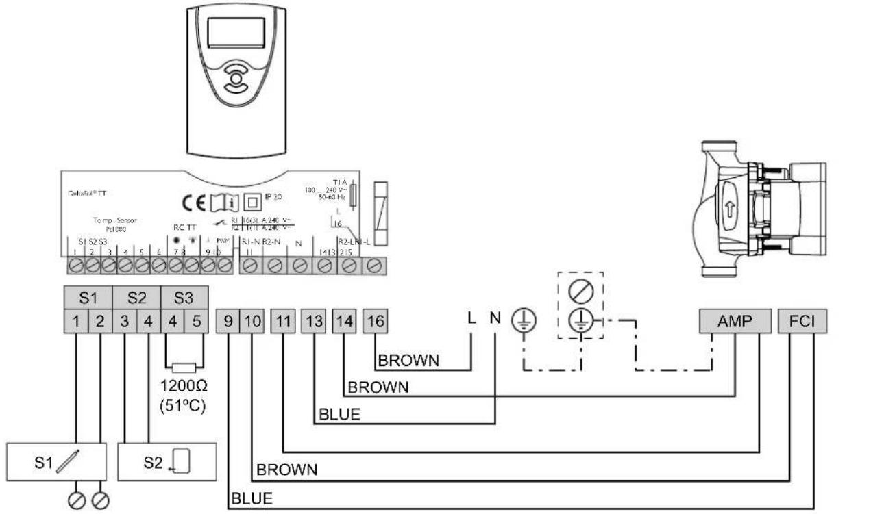
Fig.4 Electrical diagram of the SH 7 Compact unit
BA-0000020-01
Fig.5 Electrical diagram of the SH 7 Compact Top unit

BA-0000068-02

Importante
These electrical diagrams only refer to the SH 7 Compact & SH 7 Compact Top systems

Importante
The SH 7, SH 14 and SH 7 Simple systems require an external solar control to be connected.

Importante
Observe the line-neutral polarity
3.5 Characteristic curve
Fig.6 Characteristic curve of the hydraulic unit

line
| V̇ [l/h] | SH 7 COMPACT TOP | SH 7 COMPACT | SH 7 | SH 7 SIMPLE | SH 14 | | ------- | ---------------- | ------------ | ---- | ----------- | ----- | | 0 | 75 | 75 | 75 | 75 | 140 | | 200 | 75 | 75 | 75 | 75 | 135 | | 400 | 75 | 75 | 75 | 75 | 130 | | 600 | 75 | 75 | 75 | 75 | 125 | | 800 | 75 | 75 | 75 | 75 | 120 | | 1000 | 75 | 75 | 75 | 75 | 115 | | 1200 | 75 | 75 | 75 | 75 | 110 | | 1400 | 75 | 75 | 75 | 75 | 105 | | 1600 | 75 | 75 | 75 | 75 | 100 | | 1800 | 75 | 75 | 75 | 75 | 95 | | 2000 | 75 | 75 | 75 | 75 | 90 | | 2200 | 75 | 75 | 75 | 75 | 85 | | 2400 | 75 | 75 | 75 | 75 | 80 | | 2600 | 75 | 75 | 75 | 75 | 75 | | 2800 | 75 | 75 | 75 | 75 | 70 | | 3000 | 75 | 75 | 75 | 75 | 65 | | 3200 | 75 | 75 | 75 | 75 | 60 | | 3400 | 75 | 75 | 75 | 75 | 55 | | 3600 | 75 | 75 | 75 | 75 | 50 | | 3800 | 75 | 75 | 75 | 75 | 45 | | 4000 | 75 | 75 | 75 | 75 | 40 | | 4200 | 75 | 75 | 75 | 75 | 35 | | 4400 | 75 | 75 | 75 | 75 | 30 | | 4600 | 75 | 75 | 75 | 75 | 25 | | 4800 | 75 | 75 | 75 | 75 | 20 | | 5000 | 75 | 75 | 75 | 75 | 15 | | 5200 | 75 | 75 | 75 | 75 | 10 | | 5400 | 75 | 75 | 75 | 75 | - | | 5600 | 75 | 75 | 75 | 75 | - | | 5800 | 75 | 75 | 75 | 75 | - | | 6000 | - | - | - | - | - | | - | - | - | - | - | - | BA-00000S4 Description of the product
4.1 General description
The SH 7 Compact Top SH 7 Compact, SH 7, SH 14 and SH 7 Simple hydraulic units are a small and compact solution containing all elements required to easily, quickly and conveniently install solar thermal energy systems.
The solar hydraulic unit is designed to connect the accumulator and the collector field.
4.2 Operating principle
The solar pump station transports the hot heat transfer fluid from the collector field to the domestic hot water tank or the buffer tank. The solar control controls the solar pump station.

Importante
An external solar control is required to control the solar pump station for the SH 7, SH 14 and SH 7 Simple units.
4.3 Main components
Fig.7 Main components of the SH 7 Compact / SH 7 Compact Top unit

BA-0000024-01
4.3.1 SH 7 Compact/SH 7 Compact Top
The SH 7 Compact / SH 7 Compact Top system comprises the following main components:
1 Return valve
2 Safety group
3 Solar circuit pump
4 Outlet valve
5 Solar control box
6 Flow regulator
7 Air separator
Fig.8 Main components of the SH 7 and SH 14 units

BA-0000025-01
4.3.2 SH 7, SH 14
The SH 7 and SH 14 systems comprise the following main components:
1 Return valve
2 Safety unit
3 Solar circuit pump
4 Outlet valve
5 Flow regulator
6 Air separator
Fig.9 Main components of the SH 7 Simple unit

BA-0000026-01
4.3.3 SH 7 Simple
The SH 7 Simple system comprises the following main components:
1 Safety unit
2 Solar circuit pump
3 Outlet valve
4 Flow regulator
4.4 Standard delivery
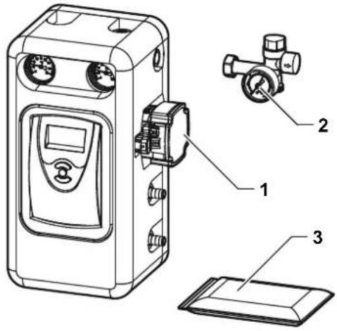
Fig.10 Standard delivery
BA-0000027-01
Each solar hydraulic unit package contains:
1 Hydraulic unit
2 Safety unit and assembly accessories
3 Documentation pack

Importante
The final product may differ from the image.
5 Before installation
5.1 Installation regulations

Advertencia
The system must be installed by a qualified professional in accordance with prevailing local and national regulations.
5.2 Electrical requirements
Tab.5 Electrical information
| Values | |
| Supply voltage 1~230 V/50 Hz | |
| Power supply Single phase |
5.3 Choice of the location
Fig.11 Recommended clearances

5.3.1 Location dimensions
Decide on the ideal position for the installation, taking into account the legal provisions and the spatial requirements for the appliance. Allow sufficient space around the system to ensure adequate access to the appliance and enable any and all maintenance operations to be carried out.
The dimensions shown in the figure should be used as a guideline.
5.3.2 Accumulator location

Atención
Install the appliance in a frost-free location.
- Position the appliance as close as possible to the draw-off points in order to minimise energy losses through the pipes.
- Place the accumulator on a base frame to facilitate cleaning of the area.
- Install the accumulator on a solid, stable structure able to bear its weight.
Fig.12 System 1
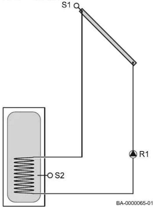
Fig.13 System 2

flowchart
graph TD
    A["Feed In"] --> B["Reactor"]
    B --> C["Reactor Chamber"]
    C --> D["S1"]
    C --> E["S2"]
    C --> F["R1"]
    C --> G["R2"]
    G --> H["Control Valve"]
    H --> I["S3"]
    style C fill:#cccccc,stroke:#333
    style D fill:#ffffff,stroke:#333
    style E fill:#ffffff,stroke:#333
    style F fill:#ffffff,stroke:#333
    style G fill:#ffffff,stroke:#333
    style H fill:#ffffff,stroke:#333
    style I fill:#ffffff,stroke:#333
5.3.3 Installation examples
Standard solar power system with an accumulator for all models of control panel.
- The solar control compares the temperature difference between the collector sensor S1 and the accumulator sensor S2. If the temperature difference is greater than or equal to the activation value set on the control for the pump R1, the pump starts up and charges the accumulator until it reaches either the value for the shutdown difference or the set maximum accumulator temperature.
Standard solar power system with an accumulator and auxiliary heater for all models of control panel.
- The solar control compares the temperature difference between the collector sensor S1 and the accumulator sensor S2. If the temperature difference is greater than or equal to the activation value set on the control for the pump R1, the pump starts up and charges the accumulator until it reaches either the value for the shutdown difference or the set maximum accumulator temperature. Once the temperature for S3 reaches the configured value or falls below it, the 3-way valve R2 changes to the direction of the boiler until the offset temperature has been reached.
Fig.14 System 3
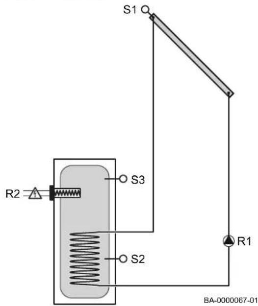
Standard solar energy system with an accumulator and auxiliary electric heating for the SH 7 Compact model.
- The solar control compares the temperature difference between the collector sensor S1 and the accumulator sensor S2. If the temperature difference is greater than or equal to the preset activation value for the pump R1, the pump starts up and charges the accumulator until it reaches either the value for the shutdown difference or the set maximum accumulator temperature. Once the temperature for S3 reaches the configured value or falls below it, the electrical resistance heating starts up and remains active until the set offset temperature has been reached.
Fig.15 System 4

flowchart
graph TD
    A["Condenser"] --> B["Reactor"]
    B --> C["S1 Q"]
    B --> D["R1"]
    B --> E["R4"]
    B --> F["T"]
    B --> G["S5"]
    B --> H["S3"]
    B --> I["S4"]
    B --> J["R3"]
BA-0000089-01
Standard solar power system with heating circuit for the SH 7 Compact Top model.
- The solar system heats a hot water cylinder which serves as a buffer tank. This buffer tank is used to heat the domestic hot water and simultaneously transfer heat to the heating circuit return. The assigned relay is connected when the difference in temperature between the buffer tank and the return is greater than the connection temperature difference.
Fig.16 System 5
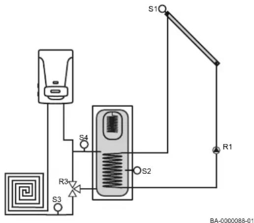
Standard solar power system with pool and heating circuit for SH 7 Compact Top model.
- The solar system is used to provide DHW and heating as a priority and, once this demand has been met, any surplus heat is used to heat the pool. The solar system heats a hot water cylinder which serves as a buffer tank. This buffer tank is used to heat the domestic hot water and simultaneously transfer heat to the heating circuit return. The assigned relay is connected when the difference in temperature between the buffer tank and the return is greater than the connection temperature difference. Also, when the buffer tank reaches the setpoint temperature, if the collectors sensor S1 is greater than the pool sensor S4, the second primary pump is activated, thereby using the surplus solar power to heat the pool.
5.3.4 Pipe diameter calculation
To size the piping, it is recommended that the linear pressure drop of the pipes does not exceed 40 mmH2O/m and the maximum speed does not exceed 2 m/s (the design flow rate taken into account is between 30 l/h·m² and 60 l/h·m²)
Tab.6 Pipe diameter with a 30% glycol concentration at 40 °C
| Number of collectors | Solar capture surface area (m2) | Maximum flow rate (l/h) (50 l/h·m2) | Recommended diameter | ||
| Nominal diameter V | (m/s) ΔP (mmH2O/m) | ||||
| 1 2 100 Dia. 10x1.0 | 0.55 88.5 | ||||
| 2 4 200 Dia. 15x1.0 | 0.42 29.3 | ||||
| 4 8 400 Dia. 18x1.0 | 0.55 36.0 | ||||
| 6 12 600 Dia. 22x1.0 | 0.53 25.2 | ||||
| 8 16 800 Dia. 22x1.0 | 0.71 41.4 | ||||
| 10 20 1000 Dia. 28x | 1.5 0.57 21.2 | ||||
| 12 24 1200 Dia. 28x | 1.5 0.68 29.1 | ||||
| 14 28 1400 Dia. 28x | 1.5 0.79 38.0 | ||||
5.3.5 Quantity of antifreeze
BAXI heat transfer fluid can be used to fill the installation, in the correct concentration for the minimum foreseeable outdoor temperature in the location. It is recommended that you use a mixture of water and glycol in the following proportions:
Tab.7 Concentration of heat transfer fluid
| Volume of heat transfer fluid 26% 33% 37% | ||
| Minimum outdoor temperature -10 °C -15 °C -20 °C |

Importante
Under no circumstances should the mixture of water and glycol exceed 40%.

Atención
The concentration of heat transfer fluid in the installation must never fall below 20%.

Advertencia
Although it is non-toxic, odourless and biodegradable, it is appropriate to take precautions when handling the product. It is recommended that you use gloves which are resistant to chemical products and wear suitable eye protection when handling the product.

Advertencia
If the fluid comes into contact with your skin, wash it with soap and water. If it comes into contact with your eyes, wash them immediately with plenty of clean running water.
6 Installation
6.1 General
The following observations must be taken into account for the hydraulic unit installation:
- Once all the hydraulic connections have been completed, check the sealing of the entire circuit.
- It is helpful to protect the collectors from the potential effects of solar radiation once the packaging has been removed, until the installation has been filled.
- If there is no demand, or it is anticipated that there will be long periods without any DHW being extracted, it is recommended to protect the system using thermal blankets.
- Once all the connections on the solar control box sensors have been completed, it is important to check that these do not run across other electrical cables as this could generate interference and alter the readout values.
- It is recommended to use a shielded cable for the sensor connections.
Before installing the solar unit, the entire installation needs to be cleaned.
The solar unit must always be installed at a lower level than the collectors so that no vapour can enter the expansion vessel in case of a blockage.
If the expansion vessel is installed at the same or a higher level than the solar unit, a heat insulation circuit is required.
The installation must be rinsed with fresh water after each draining process.
The solar unit is not suitable for direct contact with pool water or solvents.

Atención
Do not use any lubricant or grease on the installation, as this can damage the seals. Any particles of dirt, grease or lubricant residue must be rinsed out of the installation prior to installing the solar unit.
Do not use any solvents to clean the system, as this can damage plastic parts such as the pump impellers.
6.2 Hydraulic diagram
Fig.17 Hydraulic diagram

flowchart
graph TD
    A["1"] --> B["2"]
    B --> C["3"]
    C --> D["4"]
    D --> E["5"]
    E --> F["6"]
    F --> G["7"]
    G --> H["8"]
    H --> I["9"]
    I --> J["10"]
    J --> K["BA-0000029-01"]
    style A fill:#f9f,stroke:#333
    style B fill:#f9f,stroke:#333
    style C fill:#f9f,stroke:#333
    style D fill:#f9f,stroke:#333
    style E fill:#f9f,stroke:#333
    style F fill:#f9f,stroke:#333
    style G fill:#f9f,stroke:#333
    style H fill:#f9f,stroke:#333
    style I fill:#f9f,stroke:#333
    style J fill:#f9f,stroke:#333
    style K fill:#f9f,stroke:#333
- Return from the solar installation
- Flow pipe to the solar installation
- Pressure gauge
- Thermometer
- Solar pump
- Flow regulator
- Safety valve
- Filling valve
- Draining branch pipe
- Expansion vessel
6.3 Assembly
6.3.1 Assembly of the hydraulic unit

Importante
All units can be mounted on a wall rather than on the tank, as illustrated below.

Importante
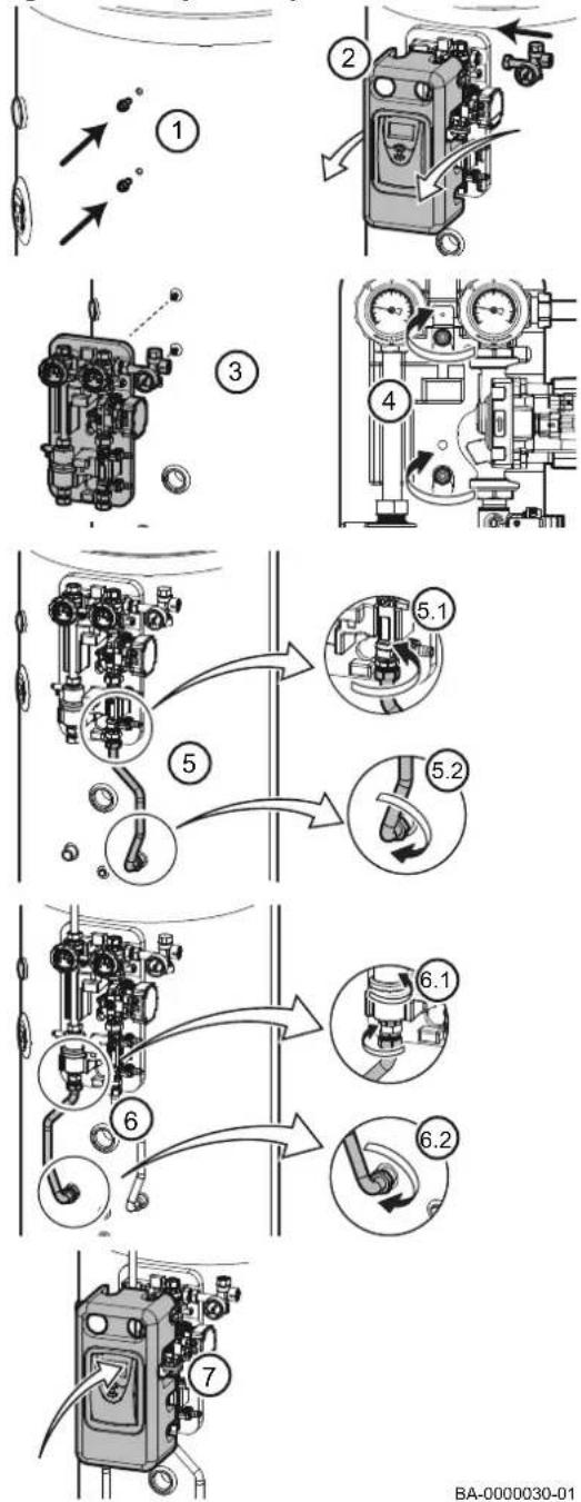
The solar unit must be installed vertically (flow rate direction from the pump going up towards the collector). This installation position means that the thermometers, pressure gauges and flowmeters are easily visible. The functions of the flowmeter, air separator and safety valve are only guaranteed if the unit is installed vertically.
Fig.18 Assembly of the hydraulic unit
flowchart
graph TD
    A["Engine 1"] --> B["Engine 2"]
    B --> C["Engine 3"]
    C --> D["Engine 4"]
    D --> E["Engine 5"]
    E --> F["Engine 6"]
    F --> G["Engine 7"]
    style A fill:#f9f,stroke:#333
    style B fill:#ccf,stroke:#333
    style C fill:#cfc,stroke:#333
    style D fill:#fcc,stroke:#333
    style E fill:#cff,stroke:#333
    style F fill:#ffc,stroke:#333
    style G fill:#cfc,stroke:#333
- Fit the screws with the lock washers on the accumulator.

Importante
Position the fastening elements without tightening the screws

Importante
The fastening screws and corresponding washers are located in a separate bag within the bag for the safety unit.
- Remove the front housing together with the solar control. Connect the safety group.
- Hang the SH DB unit in the accumulator using the fastening screws.
- Tighten the fastening screws to the tank.
- Connect the pump's flow pipe.
- Connect the return pipe to the installation's return pipe.

Importante
The connection fitting for the pipes is located in the box in the hydraulic kit.
- Refit the front housing together with the solar control.
Fig.19 Assembly of the expansion vessel

flowchart
graph TD
    A["1: Gas Cylinder"] --> B["2: Valve"]
    B --> C["3: Gas Cylinder"]
    C --> D["4: Air Conditioner"]
    D --> E["4.1: Valve"]
    E --> F["4.2: Valve"]
    style A fill:#f9f,stroke:#333
    style B fill:#ccf,stroke:#333
    style C fill:#cfc,stroke:#333
    style D fill:#fcc,stroke:#333
    style E fill:#cff,stroke:#333
    style F fill:#ffc,stroke:#333
BA-0000032-01
6.4 System connection
6.3.2 Assembly of the expansion vessel
- Connect the hydraulic connection to the expansion vessel.
- Screw on the bracket for the expansion vessel with the screws supplied.
- Hang the expansion vessel using the intended groove on the hydraulic connection. Fix the expansion vessel in place with the connector nut.
- Connect the flow line of the safety unit outlet to the expansion vessel connection.

Importante
To guarantee that all connections are leak-tight, use the sealing washers included in the kit's accessories bag.

Advertencia
Make the appliance's electrical connections in compliance with the requirements of the prevailing standards, the information given in the electrical diagrams delivered with the appliance, and the recommendations in this instruction manual.

Atención
Only qualified professionals may carry out electrical connections, always with the power off.
Earth the appliance before making any electrical connections. This machine is only electrically safe if it is correctly connected to an efficient earth system in compliance with current safety regulations.
Disconnect the power supply at the mains before carrying out any work on the appliance or accessories connected to the appliance.
The unit is supplied fully pre-wired. Do not modify the connections inside the control panel.
The mains supply is made via the connection cable pre-wired in the appliance.

Advertencia
If the power cable is damaged, for safety reasons this must only be replaced by the manufacturer, by its after sales department or by qualified personnel.
The appliance must be powered with a circuit equipped with a omnipolar switch with a contact opening distance of 3 mm. To replace the cable, use a cable approved in line with HAR H05 VV-F with a suitable cross-section.
Earthing must comply with the prevailing installation standards.

Precaución
Separate the sensor cables from the 230 V circuit cables. The installation must be fitted with a main switch.
All connections are made to the terminal blocks provided for that purpose in the system's connection box.

Importante
Failure to comply with these instructions could lead to interference and control unit malfunctioning, damage to the electronic circuitry, damage to the installation and even compromise the safety of persons.
6.5 Use of high-efficiency pumps
Fig.20 Connecting the pump wiring

BA-0000035-01

Atención
Modifications of any kind to the heat insulation are not permitted. The pump motor must not be covered.
In addition to the power cable, high-efficiency pumps with speed control require a separate cable to transmit the control signal (signal cable).
- Power supply 230 V
- Signal cable
- Blue = GND (earth)
- Brown = PWM (output signal)
6.6 Filling the installation
flowchart
graph TD
    A["Container"] --> B["Valve"]
    B --> C["Reactor Unit"]
    C --> D["Pump"]
    D --> E["Valve"]
    E --> F["Drain Tank"]
    F --> G["Outlet"]
    H["Pressure Sensor"] --> I["Valve"]
    J["Flowmeter"] --> K["Valve"]
    L["Pressure Gauge"] --> M["Valve"]
    N["Flowmeter"] --> O["Valve"]
    P["Pressure Gauge"] --> Q["Valve"]
    R["Flowmeter"] --> S["Valve"]
    T["Pressure Gauge"] --> U["Valve"]
    V["Flowmeter"] --> W["Valve"]
    X["Pressure Gauge"] --> Y["Valve"]
    Z["Flowmeter"] --> AA["Valve"]
6.6.1 General

Atención
During the start-up process, pay particular attention to cover the collectors, in order to avoid an undesirable increase in pressure.

Atención
The installation must be filled with the system empty.
6.6.2 Filling the installation
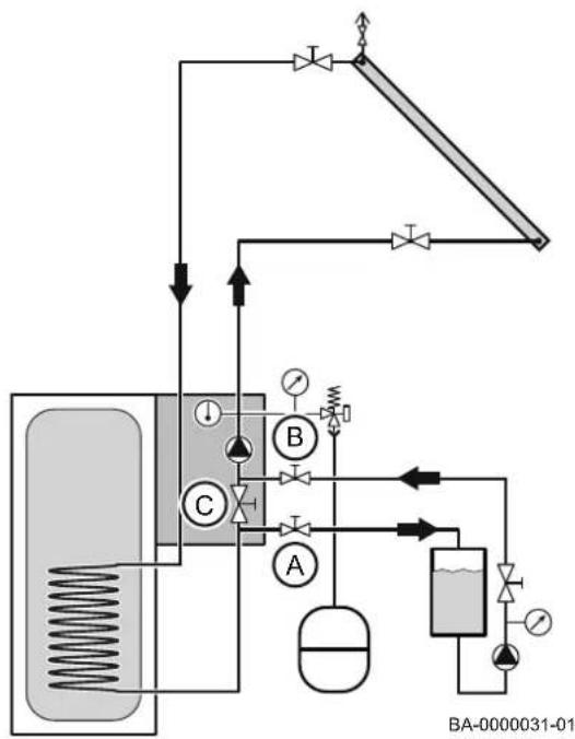
Close valves A, B and C before filling the installation.

Importante
The installation must be filled using mechanical or electrical filling equipment.
- Calculate the amount of antifreeze fluid required for the installation.

Consejo
- Mix the amount of antifreeze fluid required with tap water.
- Connect the flow of the filling unit to the inlet valve on the flowmeter (B).
- Connect the return of the filling unit to the outlet valve on the flowmeter (A).

Importante
Make sure that the valve on the flowmeter (C) is closed.
- Open the inlet and outlet valves on the flowmeter (A and B).
- Recirculate the fluid until there are no more air bubbles in the filling unit.

Importante
Only continue filling the installation once there are no more bubbles in the filling unit.
- Open the valve on the flowmeter (C).
- Close the system's drain valve (A).
- Pressurise the system to a pressure of 2 bar.
- Close the system's filling valve (B).

Importante
After a few minutes, use the pressure gauge supplied with the hydraulic unit to check that the system pressure has not dropped.
7 Solar control
7.1 Description of the solar control on the SH 7 Compact
Fig.21 Solar controller

7.1.1 Keys
The controller is operated using the three keys under the screen:
1 Forwards (+)
2 SET (selection/setting mode)
3 Back (-)
Key 1 is used to move forwards in the menu or to increase values. Key 2 is used to select channels and confirm settings. Key 3 is used to move backwards in the menu or to reduce values.
During normal operation, the screen only shows the display channels.
To switch between channels, press keys 1 and 3.
To access the setting channels, press key 1 until you reach the last display channel; then press and hold key 1 for approximately 2 seconds. When the screen shows a setting channel, the Symbol will appear on the right-hand side.
To select a setting channel, press key 2. SETs to flash. Set the desired value using keys 1 and 3. Briefly press key 2. SET will appear permanently, the value set is stored in the memory.

Importante
After four minutes of inactivity, the system will automatically switch back to the first display (status display).
7.1.2 Display
The monitoring screen comprises two parts:
• The channel indicator.
- The symbol bar.
7.1.3 Display channels
Fig.22 Channel indicator

The channel indicator has two lines:
- The upper alphanumeric line displays the channel names and the menu levels.
- The lower alphanumeric line displays the values of the channels and the adjustment parameters.
- The temperatures and temperature differences are displayed in ^ or K.
Fig.23 Symbol bar

7.1.4 Operating indicators
The symbols in the symbol bar indicate the current system status.
Tab.8 Meaning of the symbols
| Symbol permanently lit | Flashing Operating status indication | |
| 1 | Relay 1 active | |
| 2 | Relay 2 active | |
| 2+ | Rapid heating active, relay 2 active | |
| 3+ | Manual mode is active | |
| 3 times | Rapid heating is not possible because the shutdown temperature has been exceeded | |
| Maximum accumulator threshold on (the temperature of the accumulator has exceeded the maximum value) | ||
| Collector cooling function, system cooling function or accumulator cooling function active | ||
| Antifreeze option activated | ||
| Minimum threshold collector on, antifreeze function active | ||
| Collector safety disconnection activated | ||
| + | Sensor error | |
| + | Accumulator safety disconnection activated | |
| SET | Parameter | |
| Setting mode | SET | |
7.2 Description of the solar control on the SH 7 Compact Top
7.2.1 Keys and dial
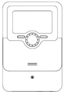
The controller is operated using the 2 keys and the dial located under the screen:
Fig.24
natural_image
Line drawing of a rectangular electronic device with a central display and control knob (no text or symbols)BA-0000087-01
1 Return to the previous menu
2 Confirm/select
3 Move up/down, increase/reduce values
4 Manual mode
5 Holiday mode
Briefly press the manual mode key to access the manual mode menu.
The holiday mode key is used to activate the holiday mode. Pressing and holding this key down for approx. 3 seconds displays the Holiday Days setting where you can set the holiday duration in days. If you set a value above 0, the set function in the Holiday mode menu will be activated and a countdown of the remaining days will be displayed from midnight. If this value is set to 0, the function remains deactivated.
7.2.2 Control indicator
The control features a control indicator with various colours in the centre of the dial. This indicates the following operating statuses:
Tab.9 Premium solar control box operating statuses
| Colour Permanently lit Flashing | ||
Green All correct Manual mode: One relay at | least in manual mode | |
Red Broken sensor cable, short-cir- | cuit on the cable of one sensor,monitor flow rate, overpressure, low pressure | |
Yellow Holiday mode ON Temperature difference too | high, night-time circulation,SUPP/RET reversed, maximum temperature exceeded,updating, MicroSD card write error |
8 Solar pump
8.1 Operating data
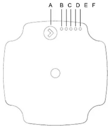
Fig.25 Solar pump operation panel
BA-0000152-01
The pump UPM3 Solar is a high-efficiency pump designed to function with and without the PWM signal, therefore enabling the following curves:
• 3 Constant curves (functioning without PWM signal)
• One PWM curve with solar profile C (stopping without PWM signal)

Importante
The pump is preset to curve with profile C PWM by default.

Importante
If the controller does not have an PWM output, do not connect the signal cable and program the pump with constant curves.
The UPM3 Solar operation panel is designed with a single button, one red/green LED and four yellow LEDs.
Tab.10 Solar pump operation panel
| Pos. Description | |
| A Press the button | |
| B LED 1 | |
| C LED 2 | |
| D LED 3 | |
| E LED 4 | |
| F LED 5 |
The operation panel displays:
- Control mode
- Status of alarms.
8.2 Pump status
If a pump has detected one or more alarms, LED 1 will change from green to red and one of the other LEDs will go yellow. Refer to the faultfinding information
If multiple alarms are active at the same time, the LEDs will only display the highest priority error. The priority is defined by the sequence in the table shown in the faultfinding information.
Tab.11 Sequence of error alarms
| LED 1 | LED 2 | LED 3 | LED 4 | LED 5 | Indications | Pump operation | Action |
| x | x | Rotor blocked | Attempt restart every 1.33 seconds | Wait and unblock the shaft | |||
| x | x | Voltage supplied too low | Warning only, pumps continues to run | Check the voltage supplied | |||
| x | x | Electrical fault | The pump has stopped running because the voltage supplied is low, or there is a serious fault | Check the voltage supplied. Replace the pump |
When there are no active alarms, the operation panel returns to operational mode.
It works with an external solar profile PWM C or in internal control with constant curve.
Tab.12 Operating status
| LED 1 | (green) | LED 2(green) | LED 3(yellow) | LED 4(yellow) | LED 5(yellow) |
| CC1 x | |||||
| CC2 x x | |||||
| CC3 x x x | |||||
| PWM C shutdown signal | x * x x x | ||||
| PWM C start-up signal | x** x x x |
(*) 1 flash per second
(**) 2 flashes per second
8.3 Pump technical data
Tab.13 Technical data
| UPM3 15-75 UPM3 15-145 | ||
| Pressure system Max. 1 | .0 MPa (10 bar) Max. 1 | .0 MPa (10 bar) |
| Minimum input pressu-re | 0.05 MPa (0.50 bar) at 95 °C of fluid tempera-ture | 0.05 MPa (0.50 bar) at 95 °C of fluid tempera-ture |
| Fluid temperature | 2-110 °C (TF110) Max. 130 °C (60 °C ambient temperature) | 2-110 °C (TF110) Max. 130 °C (60 °C ambient temperature) |
| IP class | IPX4D | IPX4D |
| Motor protection | No external protection necessary | No external protection necessary |
8.4 Pump profile
Tab.14 Electrical data, 1\~230 V/50 Hz
| Speed Units UPM3 15-75 UPM3 15-145 | |||
| Min. - Max. P | _1 [W] | 2 - 45 2 - 60 | |
| Min. - Max. P | _1/1 [A] | 0.04 - 0.48 0.04 - 0.58 | |
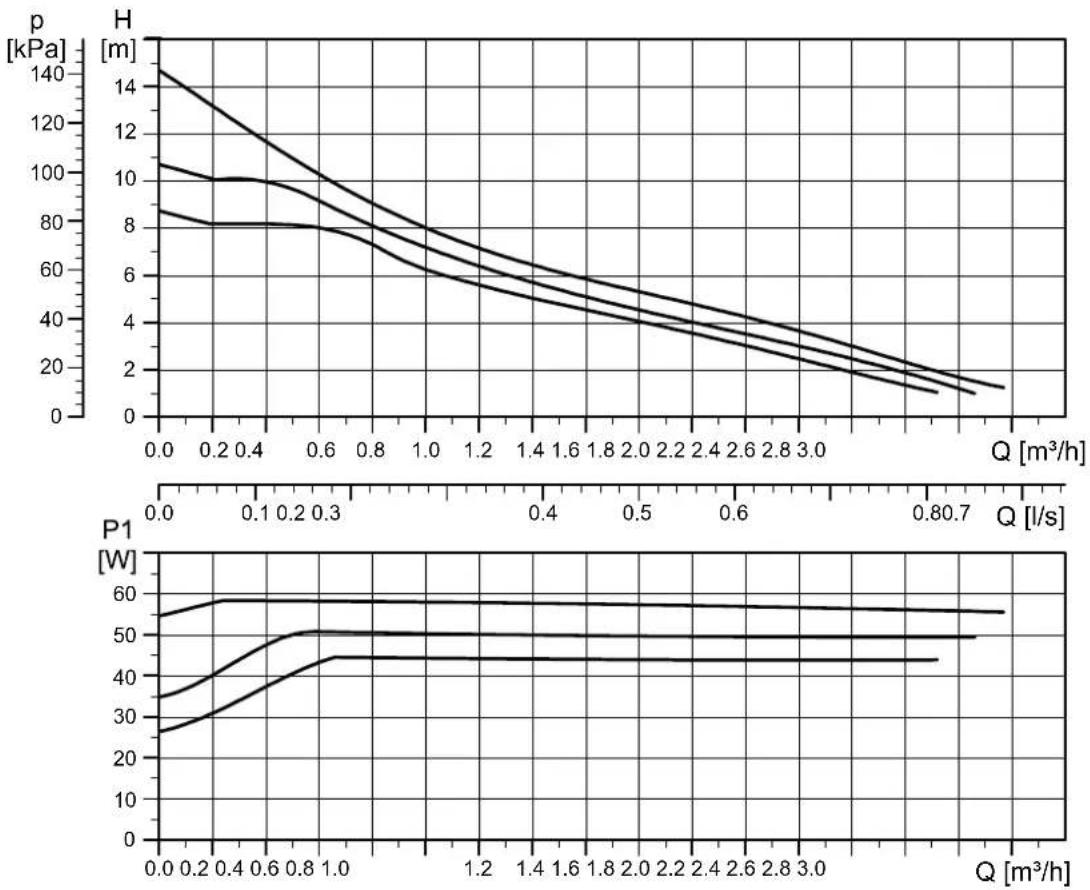
Tab.15 Data in line with the selected curve
| Selected curve Units UPM3 15–75 UPM3 15–145 | |||
| Curve 1 [C1] Nominal height 5.5 m 8.5 m | |||
| Curve 1 [C1] | P_1 nominal | 28 W 45 W | |
| Curve 2 [C2] Nominal height 6.5 m 10.5 m | |||
| Curve 2 [C2] | P_1 nominal | 35 W 52 W | |
| Curve 3 [C3] Nominal height 7.5 m 14.5 m | |||
| Curve 3 [C3] | P_1 nominal | 45 W 60 W | |
Fig.26 Pump profile UPM3 15-75

BA-0000153-01
Fig.27 Pump profile UPM3 15–145
line
| Q [m³/h] | p [kPa] H | p [kPa] P1 | p [kPa] W | p [m] | p [m] | p [l/s] | p [l/s] | | -------- | --------- | ---------- | --------- | ----- | ----- | ------- | ------- | | 0.0 | 145 | 55 | 35 | 105 | 85 | 0.0 | 0.2 | | 0.2 | 130 | 60 | 40 | 100 | 80 | 0.2 | 0.4 | | 0.4 | 115 | 58 | 45 | 95 | 78 | 0.4 | 0.6 | | 0.6 | 100 | 55 | 50 | 90 | 75 | 0.6 | 0.8 | | 0.8 | 85 | 52 | 50 | 85 | 72 | 0.8 | 1.0 | | 1.0 | 70 | 50 | 50 | 80 | 70 | 1.0 | 1.2 | | 1.2 | 60 | 48 | 50 | 75 | 68 | 1.2 | 1.4 | | 1.4 | 55 | 45 | 50 | 70 | 65 | 1.4 | 1.6 | | 1.6 | 50 | 42 | 50 | 65 | 62 | 1.6 | 1.8 | | 1.8 | 45 | 40 | 50 | 60 | 60 | 1.8 | 2.0 | | 2.0 | 40 | 38 | 50 | 55 | 58 | 2.0 | 2.2 | | 2.2 | 35 | 35 | 50 | 50 | 55 | 2.2 | 2.4 | | 2.4 | 30 | 32 | 50 | 45 | 52 | 2.4 | 2.6 | | 2.6 | 25 | 30 | 50 | 40 | 50 | 2.6 | 2.8 | | 2.8 | 20 | 28 | 50 | 35 | 48 | 2.8 | 3.0 | | 3.0 | 15 | 25 | 50 | 30 | 45 | 3.0 | 3.2 | | >3.0 | ~10 | ~45 | ~45 | ~10 | ~40 | >3.2 | >3.4 | | >3.2 | ~8 | ~42 | ~45 | ~8 | ~38 | >3.2 | >3.4 | | >3.4 | ~6 | ~40 | ~45 | ~6 | ~35 | >3.2 | >3.4 | | >3.6 | ~4 | ~38 | ~45 | ~4 | ~32 | >3.2 | >3.4 | | >3.8 | ~2 | ~35 | ~45 | ~2 | ~30 | >3.2 | >3.4 | | >4.0 | ~1 | ~32 | ~45 | ~1 | ~28 | >3.2 | >3.4 | | >4.2 | ~0.5 | ~30 | ~45 | ~0.5 | ~25 | >3.2 | >3.4 | | >4.4 | ~0.2 | ~28 | ~45 | ~0.2 | ~22 | >3.2 | >3.4 | | >4.6 | ~0.1 | ~25 | ~45 | ~0.1 | ~20 | >3.2 | >3.4 | | >4.8 | ~0.0 | ~22 | ~45 | ~0.0 | ~18 | >3.2 | >3.4 | | >5.0 | ~-0.1 | ~20 | ~45 | -0.1 | ~15 | >3.2 | >3.4 | | >5.2 | ~-0.2 | ~18 | ~45 | -0.2 | ~12 | >3.2 | >3.4 | | >5.4 | ~-0.3 | ~15 | ~45 | -0.3 | ~10 | >3.2 | >3.4 | | >5.6 | ~-0.4 | ~12 | ~45 | -0.4 | ~8 | >3.2 | >3.4 | | >5.8 | ~-0.5 | ~10 | ~45 | -0.5 | ~6 | >3.2 | >3.4 | | >6.0 | ~-0.6 | ~8 | ~45 | -0.6 | ~4 | >3.2 | >3.4 | | >6.2 | ~-0.7 | ~6 | ~45 | -0.7 | ~2 | >3.2 | >3.4 | | >6.4 | ~-0.8 | ~4 | ~45 | -0.8 | ~1 | >3.2 | >3.4 | | >6.6 | ~-0.9 | ~2 | ~45 | -0.9 | ~0 | >3.2 | >3.4 | | >6.8 | ~-1.0 | ~1 | ~45 | -1.0 | ~-1 | >3.2 | >3.4 | | >7.0 | ~-1.1 | ~-1 | ~45 | -1.1 | ~-2 | >3.2 | >3.4 | | >7.2 | ~-1.2 | ~-2 | ~45 | -1.2 | ~-3 | >3.2 | >3.4 | | >7.4 | ~-1.3 | ~-3 | ~45 | -1.3 | ~-4 | >3.2 | >3.4 | | >7.6 | ~-1.4 | ~-4 | ~45 | -1.4 | ~-5 | >3.2 | >3.4 | | >7.8 | ~-1.5 | ~-5 | ~45 | -1.5 | ~-6 | >3.2 | >3.4 | | >8.0 & above for Q range:BA-0000154-01
9 Commissioning
9.1 General
The system is commissioned to enable it to be used for the first time, after it has been out of service for a prolonged period or after any circumstance requiring a full reinstallation of the system.
Commissioning the system enables the user to check the various settings and perform the necessary checks to start up the system in complete safety.
9.2 Checklist before commissioning
- Check that the installation and the system are filled with heat transfer fluid and have been bled correctly.
- Check the tightness of the pipe connections.
- Bleed the system if necessary.
- Check the pressure shown on the unit's pressure gauge.
- Check the electrical connections.
- Check that there is an earth connection and the corresponding earth connection circuit.
9.3 Commissioning procedure for SH 7 Compact
9.3.1 Settings
Once the filling procedure is complete, the system must be connected to the power supply.
Although the system is configured in the factory, if the control is reset, the first time that the control is switched on, the initialisation phase begins and the commissioning menu launches automatically.
The commissioning menu guides the user through the key adjustment parameters required to operate the system.

Importante
All the settings made during commissioning can be changed later if necessary, via the corresponding parameter. Additional functions and options can also be enabled and adjusted.
Language
Fig.28 Language
Select the language required.

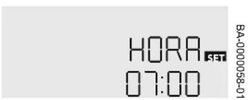
Time
Fig.29 Time
Set the clock.
System
Fig.30 System
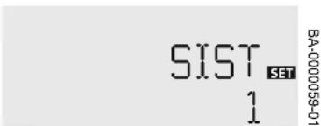
Select the solar system required.
■ Maximum accumulator temperature
Fig.31 Maximum accumulator temperature

Adjust the desired maximum temperature of the accumulator.
■ Connection temperature for the auxiliary heating
Fig.32 Connection temperature

Set the required connection temperature.
■ Shutdown temperature for the auxiliary heating
Fig.33 Shutdown temperature

Set the required shutdown temperature.
■ Finalising settings in the commissioning menu
Fig.34 Confirmation

After accessing the last channel in the commissioning menu, a safety request is displayed to confirm the settings made. To confirm the settings made, press the central key.
9.3.2 Factory setting values
Tab.16 Factory values
| Channel Meaning Factory set- | ting | |
| SIST System 1 | ||
| DT O Difference in connection temperature 6.0 K | ||
| DT F Difference in shutdown temperature 4.0 K | ||
| DT N Difference in nominal temperature 10.0 K | ||
| A MX Maximum accumulator temperature 60 °C | ||
| AUM Increase 2 k | ||
| CSEG Collector temperature limit 130 °C | ||
| ORC Collector cooling option OFF | ||
| OMNC | Minimum threshold collector option OFF | |
| OAH | Antifreeze option | OFF |
| OCT | Vacuum tube collector option | OFF |
| ODB Drainback option OFF | ||
| ORSI System cooling option OFF | ||
| ORA Accumulator cooling option OFF | ||
| OT1 Option thermostat 1 ON | ||
| CA1O Connection temperature thermostat 1 40 °C | ||
| CA1F Shutdown temperature thermostat 1 45 °C | ||
| TIR Thermostat 1 cooling OFF | ||
| t101 Thermostat 1 connection time 1 07:00 | ||
| t1F1 Thermostat 1 shutdown time 1 08:00 | ||
| t201 Thermostat 1 connection time 2 11:00 | ||
| t2F1 Thermostat 1 shutdown time 2 12:00 | ||
| t301 Thermostat 1 connection time 3 18:00 | ||
| t3F1 Thermostat 1 shutdown time 3 20:00 | ||
| ODT | Thermal disinfection option | OFF |
| REL1 | Signal type from R1 SOL | |
| MIN | Minimum speed | 30% |
| MAX Maximum speed 100% | ||
| MAN1 | Manual mode R1 | Auto |
| MAN2 | Manual mode R2 | Auto |
| IDIO | Language | ES |
9.4 Commissioning procedure for SH7 Compact Top
9.4.1 Settings
Once the filling procedure is complete, the hydraulic unit must be connected to the power supply.
Although the system is configured in the factory, if the control is reset, the first time that the control is switched on, the initialisation phase begins (during which the central key flashes red) and the commissioning menu launches automatically.
The commissioning menu guides the user through the key adjustment parameters required to operate the system.
The commissioning menu comprises the parameters described below. To make an adjustment, set the desired value using the central dial and press the right-hand key to confirm. The following parameter will appear on the screen.
Language
Fig.35 Language
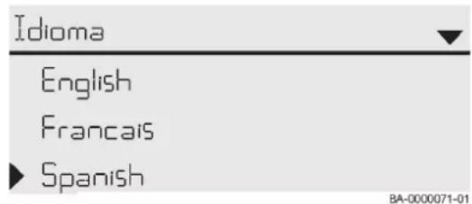
Select the language required.
Fig.36 Temperature unit

Fig.37 Flow rate unit

Fig.40 Switching between summer and winter time

Units
Select the unit of temperature.
Select the flow rate unit.
Select the unit of pressure.
Select the unit of energy.
■ Switching between summer and winter time
Enable or disable automatic switching between summer and winter time.
Fig.41 Time
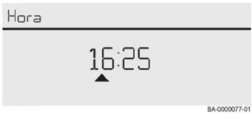
Fig.42 Date

Fig.43 Selection: System or diagram
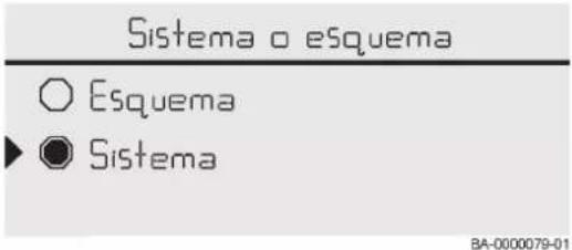

Fig.44 Finalising settings in the commissioning menu

Time
Set the clock. Set the hours first, then the minutes.
Date
Adjust today's date. Set today's date by setting the year first, then the month and the day.
■ Selection: System or diagram
Select to configure the controller with a system.
Select solar system 1. This solar system has the following configuration of sensors and relays:
Tab.17 Sensors and relays in solar system 1
| Sensors | |||
| Collector 1 S1 Solar pump R1; PWMA | |||
| Lower accumulator S2 | -- | ||
■ Finalising settings in the commissioning menu
After selecting the system or entering the diagram number, a security request is displayed. If the request is confirmed, the settings will be saved.
To confirm the security request, press the right-hand button.
To return to the commissioning menu, press the left-hand button. After confirming the safety request, the solar control is ready to use and should make optimal use of the system using the factory settings.

Importante
All the settings made during commissioning can be changed later if necessary, via the corresponding parameter. Additional functions and options can also be enabled and adjusted.
9.4.2 Premium factory setting values
Solar
Tab.18 Factory values on the solar menu
| Basic settings | |
| System 1 | |
| Collector | |
| Min. coll. temp. 10 °C | |
| Safety limit 130 °C | |
| Accumulator | |
| T_on | 6.0K |
| T_off | 4.0K |
| T_nom. | 10.0K |
| Acc. nom. temp. 60 °C | |
| Acc. max. temp. 60 °C | |
| AccHys 2.0K | |
| Increase 2.0K | |
| t_min | 30 s |
| Minimum speed 40% | |
| Accumulator Activated | |
■ Installation
Tab.19 Factory values on the installation menu
| Optional functions | |
| Parallelling relay | |
| Relay R4 | |
| Reference relay R1 | |
| Extend Deactivated | |
| Delay Deactivated | |
| Speed Deactivated | |
| Reverse Deactivated | |
| Function Activated | |
■ Energy meter
Tab.20 Factory values on heating menu
| Energy meter | |
| Feed flow sensor S3 | |
| Return flow sensor | S6 |
| Flow sensor | Activated |
| Flow sensor | S6 |
| Fluid type | Water |
| Function Deactivated | |
■ Inputs/Outputs
Tab.21 Factory values on the inputs menu
| Inputs | ||
| S1 | PT1000 | |
| S2 | PT1000 | |
| S3 PT1000 | ||
| S4 PT1000 | ||
| S5 None | ||
| S6 Type VFS | ||
| Min. 5 l/min | ||
| Max. 100 l/min | ||
| S7 None | ||
Tab.22 Factory values on the outputs menu
| Outputs | ||
| R1 Signal 0-10 V | ||
| Output A | ||
| Type Solar | ||
| Min. speed 40% | ||
| Max. speed 100% | ||
| R2 Signal Standard | ||
| Min. speed 100% | ||
| Max. speed 100% | ||
| R3 Free | ||
| R4 Signal Standard | ||
Tab.23 Configured inputs/outputs
| Solar | |
| Collector S1 | |
| Lower. accum. S2 | |
| Primary pump R1 | |
| Parallelling relay R4 | |
Tab.24 Heat exchanger
| Heat exchanger | |
| Heat exchanger heat S3 | |
| Heat exchanger consumption S2 | |
| Secondary pump | R2 |
Tab.25 Energy meter
| Energy meter | |
| Energy meter feed flow | S3 |
| Energy meter return flow | S6 |
| Energy meter flow rate | S6 |
10 Maintenance
10.1 General

Advertencia
Maintenance work must be carried out by a qualified professional.

Advertencia
Failure to service the system will void the warranty.

Advertencia
Use only genuine spare parts.

Peligro
There is always a risk that they pump could become extremely hot, depending on the operating conditions of the pump as well as the installation (temperature of the flow medium). Risk of burns when touching the pump!
10.2 Standard inspection and maintenance operations
Fig.45 Switching off the power supply


Disconnect the appliance from the power mains before carrying out any maintenance operations.
Have a service carried out at least once a year, or more often, depending on the regulations in force in your country:
- Check for leaks in the system.
- Check the hydraulic pressure.
- Check the fluid drained via the safety valve and fill the installation if necessary.
- Check the status of the components.
- Check the maximum flow rate of the pump.
- Check the electrical connections.
- Check that the collectors are not too dusty. The collectors can be cleaned with water, but they must be cold to avoid breaking the glass.
- Check if the collector installation shows any signs of damage or if there is any accumulated waste.
- Check if the collector shows any signs of corrosion.
- Check if there is any damage or leaks in the accessories and pipework, and check the condition of the insulation on these components.
10.3 Specific inspection and maintenance operations
Fig.46 Replacement of the expansion vessel

natural_image
Simple line drawing of a gasifier with a valve and cooling tower (no text or symbols)BA-0000064-01
The expansion vessel has a non-return valve so that it can be removed without having to drain the system should it need to be replaced.
11 Troubleshooting
11.1 General malfunctions

Always disconnect the unit from the power supply before removing the cover from the solar control.
Tab.26 General malfunctions
| Fault Possible cause Solution | ||
| The collector field installation does not heat the accumulator water. | The surface of the collectors is dirty. | Clean the surface of the collectors. |
| The flow rate is insufficient. | Check the flow rate and, if necessary, adjust it to the correct value using the flow regulator. | |
| Incorrect sensor reading. | Check that the sensors are correctly positioned. If faulty, replace. | |
| Solar control malfunction. | Check the parameter configuration of the control. If in doubt, contact the technical department. | |
| No fluid circulating in the installation. | The installation has not been correctly sized. | The installation's pipe network does not meet the criteria in terms of the required dimensions and arrangement, therefore the fluid cannot circulate. |
| System electrical fault. | Check the electrical supply at various points in the system. | |
| Air found in the pump intake. | Bleed the entire system. Repeat the installation filling process if necessary. | |
| The solar pump does not run. | The pump is blocked. | Disassemble the pump and check that there is no obstruction. If the error persists, contact the technical department. |
| The solar pump is not powered. | Check the pump connections. Check the electrical supply to connection R1. | |
| The solar control is incorrectly configured. | Check the configuration of the solar control. | |
| The pump starts and stops intermittently. | The temperature difference in the control is too small. | Change the ΔTon and ΔToff settings to the correct values. |
| Collector sensor fitted in the wrong place. | Position the temperature sensor at the hottest output of the collector. | |
| The pump starts running after a long delay. | ΔTon connection temperature difference too great. | Change the ΔTon and ΔToff settings to the correct values. |
| Collector sensor incorrectly positioned. | When the sun is shining, briefly adjust the solar pump in manual mode, and check if the temperature of the collectors increases. | |
| The accumulator cools down overnight. | The solar circuit pump works overnight. | Check the operating status of the pump. |
| Check the configuration of the solar control. | ||
| The solar pump does not run although the temperature of the collectors is greater than the temperature of the accumulator. | The temperature difference in the control is too great. | Change the ΔTon and ΔToff settings to the correct values. |
| The solar control is incorrectly configured. | Check the configuration of the solar control. | |
| Check the position of the sensors. | ||
12 Decommissioning
12.1 Decommissioning procedure
Fig.47 Switching off the power supply

natural_image
Illustration of electrical wall connections and a black X symbol (no text or labels)MW-0000149-1
If you need to decommission the SH DB system, either temporarily or permanently, proceed as follows:
- Switch off the power supply to the system.
- Wait until the fluid has drained out of the installation and is stored in the SH DB system.
- Close all the valves on the system.
- Drain the system.
13 Disposal
13.1 Disposal and recycling
Fig.48 Recycling

Fig.49 Switching off the power supply


Advertencia
Removal and disposal of the system must be carried out by a qualified installer in accordance with local and national regulations.
Disassemble the system as follows:
- Switch off the power supply to the system.
- Close all the valves on the system.
- Drain the system via the valve used for filling/draining.

Advertencia
Handle with care: The fluid inside can be very hot.

Importante
The fluid inside is a mix of glycol and water; do not pour it down the drain – recycle it appropriately.
- Disconnect all the inlets and outlets on the system.
- Recycle or dispose of the system.
© Copyright
All technical and technological information contained in these technical instructions, as well as any drawings and technical descriptions supplied, remain our property and shall not be multiplied without our prior consent in writing. Subject to alterations.
BAXI
Tel. +34 902 89 80 00
www.baxi.es
informacion@baxi.es



CE
BAXI
- Dear Customer,
- Safety
- General safety instructions
- General safety
- Peligro
- Atención
- Importante
- Advertencia
- Electrical safety
- Recommendations
- Liabilities
- Manufacturer's liability
- Installer's liability
- User's liability
- About this manual
- General
- Symbols used
- Symbols used in the manual
- Technical specifications
- Directives
- Technical data
- Dimensions and connections
- SH 7 Compact / SH 7 Compact Top
- SH 7, SH 14
- SH 7 Simple
- Electrical diagram
- Characteristic curve
- Description of the product
- General description
- Operating principle
- Main components
- SH 7 Compact/SH 7 Compact Top
- SH 7, SH 14
- SH 7 Simple
- Standard delivery
- Before installation
- Installation regulations
- Electrical requirements
- Choice of the location
- Location dimensions
- Accumulator location
- Installation examples
- Pipe diameter calculation
- Quantity of antifreeze
- Installation
- General
- Hydraulic diagram
- Assembly
- Assembly of the hydraulic unit
- System connection
- Assembly of the expansion vessel
- Precaución
- Use of high-efficiency pumps
- Filling the installation
- General
- Filling the installation
- Consejo
- Solar control
- Description of the solar control on the SH 7 Compact
- Keys
- Display
- Display channels
- Operating indicators
- Description of the solar control on the SH 7 Compact Top
- Keys and dial
- Control indicator
- Solar pump
- Operating data
- Pump status
- Pump technical data
- Pump profile
- Commissioning
- General
- Checklist before commissioning
- Commissioning procedure for SH 7 Compact
- Settings
- Language
- Time
- System
- ■ Maximum accumulator temperature
- ■ Connection temperature for the auxiliary heating
- ■ Shutdown temperature for the auxiliary heating
- ■ Finalising settings in the commissioning menu
- Factory setting values
- Commissioning procedure for SH7 Compact Top
- Settings
- Units
- ■ Switching between summer and winter time
- Date
- ■ Selection: System or diagram
- Premium factory setting values
- Solar
- ■ Installation
- ■ Energy meter
- ■ Inputs/Outputs
- Maintenance
- General
- Standard inspection and maintenance operations
- Specific inspection and maintenance operations
- Troubleshooting
- General malfunctions
- Decommissioning
- Decommissioning procedure
- Disposal
- Disposal and recycling
- © Copyright
Brand : Baxi
Model : SH 7 Compact
Category : Unité hydraulique solaire