
SA9500 - Heating DCG - Free user manual and instructions
Find the device manual for free SA9500 DCG in PDF.


| Product Type | Fan Heater |
| Model | SA9500 |
| Brand | DCG |
| Heating Element | Ceramic |
| Power Settings | Low (1000W) / High (2000W) |
| Thermostat | Adjustable thermostat with auto shut-off |
| Timer | Up to 12 hours |
| Oscillation | Yes, 60° |
| Remote Control | Included |
| Display | LED digital display |
| Dimensions (W x D x H) | 20 cm x 15 cm x 30 cm |
| Weight | 1.8 kg |
| Power Supply | 220-240 V, 50 Hz |
| Noise Level | ≤ 45 dB |
| Safety Features | Tip-over switch, overheat protection, cool-touch casing |
| Filter Type | Washable mesh filter |
| Cleaning | Remove dust with soft cloth; clean filter monthly |
| Spare Parts | Filter, remote control available |
| Repairability | User replaceable filter; professional repair for other parts |
| Warranty | 2 years |
Frequently Asked Questions - SA9500 DCG
User questions about SA9500 DCG
0 question about this device. Answer the ones you know or ask your own.
Ask a new question about this device
Download the instructions for your Heating in PDF format for free! Find your manual SA9500 - DCG and take your electronic device back in hand. On this page are published all the documents necessary for the use of your device. SA9500 by DCG.
USER MANUAL SA9500 DCG
natural_image
Black outdoor heater with coiled glass panel and LED indicator, no visible text or symbols on bodyPATIO DA ESTERNO
PATIO HEATER
MANUALE D'USO
USER MANUAL
PER LA VOSTRA SICUREZZA E PER UN CORRETTO USO DELL'APPARECCHIO LEGGERE ATTENTAMENTE E CONSERVARE QUESTO MANUALE

ATTENZIONE
PRIMA DI METTERE IN FUNZIONE QUESTA STUFA, LEGGERE LE SEGUENTI RACCOMANDAZIONI PER LA SICUREZZA.
natural_image
Simple line drawing of a lamp inside a transparent cube (no text or symbols)natural_image
Interior view of a large industrial facility with pipes and a bucket pouring liquid (no visible text or symbols)
natural_image
Close-up of a metal pipe fitting with a water bottle, attached to a concrete structure (no visible text or symbols)natural_image
Technical line drawing of a circular mechanical component with a central rod and base, no text or symbols present
natural_image
Diagram of a mechanical component with a curved pipe and base, showing no text or symbols- Turn the black knob to the "PILOT" position
- Push and turn the black knob to "OFF" position
- Turn off the regulator on the gas cylinder and disconnect.
CONSERVAZIONE
natural_image
Line drawing of a mechanical assembly with two components and a cylindrical base (no text or symbols)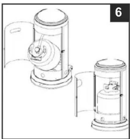
natural_image
Technical line drawing of two mechanical components with no visible text or symbolsFOR YOUR SAFETY PLEASE READ CAREFULLY AND KEEP THIS INSTRUCTION OF USE

WARNING
PLEASE READ THE FOLLOWING SAFETY ADVICE PRIOR TO THE OPERATION OF THIS HEATER If you smell gas:
- Switch off the gas regulator.
- Extinguish any open flame.
- If the smell continues immediately call your gas supplier or your fire department. 4. Do not store or use flammable liquids in the vicinity of this heater.
- Any gas cylinders not connected for use shall not be stored in the vicinity of this heater.

WARNING
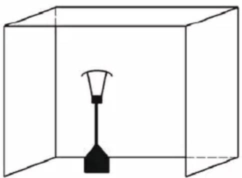
For use outdoors or in areas that have ample ventilation.
An amply ventilated area must have a minimum of 25 % of the surface area open. The surface area is the sum of the walls surface.
natural_image
Simple line drawing of a lamp inside a transparent cube (no text or symbols)Improper installation, adjustment, alteration, service or maintenance can cause injury or property damage. Read the installation, operating and maintenance instructions thoroughly before installing or servicing this equipment.

WARNING
Read all of these instructions before installation and use.
- This appliance must be installed and the gas cylinder stored in accordance with LPG storage regulations.
• Do not obstruct the ventilation holes of the cylinder housing.
• Do not move the heater when in operation. - Switch off the gas regulator before moving the heater.
• The rubber hose should be inspected and changed on a yearly basis.
• This heater is designed to be used with max 13kg patio/leisure propane gas cylinders.

WARNING
he user assumes all risk in assembly and operation of gas heater. Failure to follow the warnings and instructions in this manual can result in several personal injury, death, property damage. If user can not read or fully understand the instruction manual, please contact your dealer. Manufacturer or supplier will not be responsible for user's negligence.
SAFETY PRECAUTIONS
Read the instructions before using this appliance. The appliance must be installed in accordance with the instructions.
• Do not use this patio heater indoors, as it may cause personal injury or property damage.
- This outdoor heater is not intended to be installed on recreational vehicles and/or boats. Installation and repair should be done by a qualified service person.
• Improper installation, adjustment, alteration can cause personal injury or property damage.
• Do not attempt to alter the unit in any manner.
• Never replace or substitute the regulator with any regulator other than the factory-suggested replacement.
• Do not move the appliance when in operation.
- Shut off the valve at the gas cylinder or the regulator before moving the appliance.
• In case of violent wind particular attention must be taken against tilting of the appliance.
• Do not store or use gasoline or other flammable vapors or liquids in the heater unit.
- The whole gas system, hose, regulator, pilot or burner should be inspected for leaks or damage before use, and at least annually by a qualified service person.
- All leak tests should be done with a soap solution. Never use an open flame to check for leaks. Do not use the heater until all connections have been leak tested.
• Turn off the gas valve immediately if smell of gas is detected. Turn Cylinder Valve
OFF. If leak is at Hose/ Regulator connection: tighten connection and perfect test. If bubbles continue appearing should be returned to hose's place of purchase. If leak is at Regulator/Cylinder Valve connection: disconnect, reconnect, and perform another. If you continue to see bubbles after several attempts, cylinder valve is defective and should be returned to cylinder's place of purchase.
- Do not transport heater while it's operating.
- Do not move the heater after it has been turned off until the temperature has cooled down. Keep the ventilation opening of the cylinder enclosure free and clear of debris.
- Do not paint the radiant screen, control panel or top canopy reflector.
- Control compartment, burner and circulation air passageways of the heater must be kept clean. Frequent cleaning may be required as necessary.
- The LP tank should be turned off when the heater is not in use. Check the heater immediately if any of the following occurs:
-
The heater does not reach temperature.
-
The burner makes a popping noise during use (a slight noise is normal extinguished).
-
Smell of gas in conjunction with extreme yellow tipping of the burner flames.
- The gas regulator/hose assembly must be located out of pathways where people may trip over it or in areas where the hose will not be subject to accidental damage.
- Any guard or other protective device removed when servicing the heater must be replaced before operating the heater. Adults and children should stay away from high temperature surfaces to avoid burns or clothing ignition.
• Children should be carefully supervised when they are in the area of the heater.
• Clothing or other flammable materials should not be hung on the heater or placed on or near the heater.
- The gas cylinder should only be changed in a ventilated area, away from (candles, cigarettes, and other flame producing appliances)
• Do not obstruct the ventilation holes of the cylinder housing.
• In the event of gas leak, the appliance shall not be used or if alight, the gas regulator should be turned off immediately and the appliance should be inspected thoroughly before it is used again.
- Inspect the gas hose before every use. If it shows signs of cracking, splitting or other deterioration it should be replaced with new hose of the same length and of the equivalent quality.
- The use of this appliance in enclosed areas can be dangerous and is connection of hose and regulator, and connection of regulator and hose, please refer to the photos shown below.

natural_image
Interior view of a stainless steel industrial facility showing a hand pouring liquid into a white bowl (no visible text or symbols)
natural_image
Close-up of a metal pipe fitting with a circular opening, mounted on a metal frame (no visible text or symbols)To assist connecting the regulator, carefully place the rubber hose into an insulated cup of boiling hot water. This allows the rubber hose to expand and allow the regulator to be connected easily. After connecting the regulator, tighten the hose clip with a screwdriver.
- This product contains small batteries. Swallowed small batteries can cause CHOCKING HAZARD. Seek immediate medical attention if batteries are swallowed or inhaled. Keep children away from the small batteries
HEATER STAND AND LOCATION
- The heater is primarily for outdoor use only. Always ensure that adequate fresh air ventilation is provided.
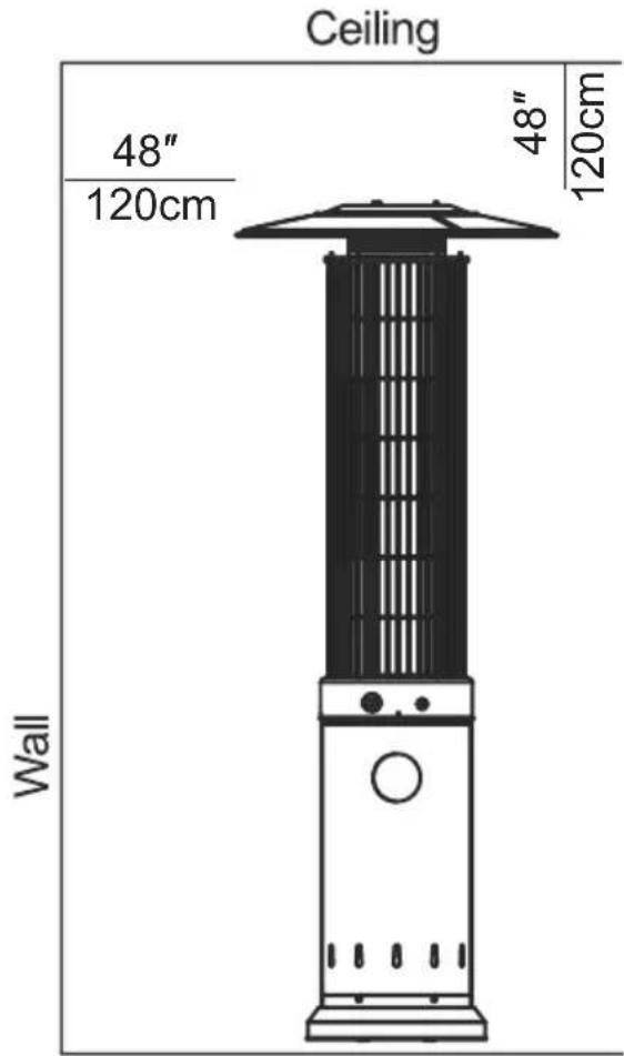
• Always maintain proper clearance to non-protected combustible materials i.e. top 120 cm and sides 120 cm minimum.
• Heater must be placed on level firm ground. - Never operate heater in an explosive atmosphere like in areas where gasoline or other flammable liquids or vapors are stored.
GAS REQUIREMENTS
• This heater is primarily designed to be used with propane gas.
- Butane gas may also be used with the appropriate regulator however butane freezes at degrees so will not be ideal to be used during cold temperatures.
• A dented, rusted or damaged cylinder may be hazardous and should be checked by your gas supplier before being used with this heater. • Never connect an unregulated cylinder to the heater
LEAKAGE TEST
Gas connections on the heater are leak tested at the factory prior to shipment. A complete gas leak check must be performed at the installation site due to possible mishandling during the transit process.
WARNING
Leak testing: Do not smoke while performing this test, and remove all sources of ignition. A full gas cylinder is required. This test must be done before initial use, annually and whenever any gas Components are replaced or serviced.
- Mix a solution of water and washing up liquid, then pour onto the connection between the joints and connections of the regulator, hose, manifolds and valves. See Leak Testing Diagram below for areas to check. Turn all burner controls to the off position. Turn the gas regulator ON.

natural_image
Technical line drawing of a circular mechanical component with a central rod and base, no text or symbols present
natural_image
Diagram of a mechanical component with a curved pipe and base, showing motion direction (no text or symbols)• If no bubbles are present - This indicates the connection is leak safe.
• If bubbles are present - Tighten the hose clip further and retest for leaks
• If bubbles continue to appear -please contact your gas supplier or heater distributor
2. If the leak cannot be stopped, immediately shut off the gas supply and disconnect it. 3. Do not use the patio heater until the leak has been corrected
FUEL GAS ODOR
LP gas and natural gas have manmade odorants added specifically for detection of fuel gas leaks. If a gas leak occurs you should be able to smell the fuel gas. Since Propane (LP) is heavier than air you should smell for the gas odor low to the floor.
FUEL GAS ODOR
LP gas and natural gas have manmade odorants added specifically for detection of fuel gas leaks. If a gas leak occurs you should be able to smell the fuel gas. Since Propane (LP) is heavier than air you should smell for the gas odor low to the floor.
ANY GAS ODOR IS YOUR SIGNAL TO GO INTO IMMEDIATE ACTION.
- Do not take any action that could ignite the fuel gas. Do not operate any electrical switches. Do not pull any power supply or extension cords. Do not light matches or any other source of flame. Do not use your telephone.
• Get everyone out of the building and away from the area immediately.
• Propane (LP) gas is heavier than air and may settle in low area. When you have reason to suspect a propane leak, keep out of all low area. - Use your neighbor's phone and call your fuel gas supplier and your fire department. Do not reenter the building or area.
- Stay out of the building and away from the area until declared safe by the firefighters and your fuel gas supplier.
• Finally, let the fuel gas service person and the firefighters check for escaped gas. Have them air out the building and area before you return. Properly trained service people must repair any leaks, check for further leakages, and then relight the appliance for you.
WARNING: This product contains small batteries. Swallowed small batteries can cause CHOKING HAZARD. Seek immediate medical attention if batteries are swallowed or inhaled. Keep children away from the small batteries

TO TURN ON THE HEATER
- Ensure the black knob is at the "OFF" position
- Connect the gas regulator to a compatible gas cylinder
- Ensure a battery has been inserted into the red ignition button.
- Push and tum the control knob anticlockwise to the "PILOT" position and hold in for 60 seconds
- While holding down the black knob, press the igniter button several times until the pilot flame lights.
- Once the blue pilot light flame stays alight constantly, release the black knob slowly.
- Turn the black knob to the desired temperature setting(High/low).
Note:
- If a new tank has just been connected, please allows at least on minute for the air in the gas pipeline to purge out through the pilot hole.
- When lighting the pilot flame make sure that the variable control knob is continuously pressed down while pressing the igniter button. Variable control knob can be released after the pilot flame lights.
• If the pilot flame does not light or it goes out, REPEAT STEP 3.
• A 5 minutes complete shut off period is necessary before relighting.
TO TURN THE HEATER OFF
- Turn the black knob to the "PILOT" position
- Push and turn the black knob to "OFF" position
- Turn off the regulator on the gas cylinder and disconnect.
STORAGE
- Always close the gas valve of the gas cylinder after use or in case of a disturbance.
- Remove the pressure controller and the hose.
- Check the tightness of the gas valve and for damage. If you suspect a damage, have it changed by your gas dealer.
- Never store liquid gas cylinder in a sub-terrain, or at places without adequate air ventilation.
CLEANING AND CARE
- Wipe off powder coated surfaces with soft, moist rag. For lacquer surface, use suitable cleaners. Do not clean heater with cleaners that are combustible or corrosive.
- Remove debris from the burner to keep it clean and safe for use.

PARTS LIST
| PART DESCRIPTION QUANTITY | ||
| A | Reflector | 1 |
| B | Protective Guard | 1 |
| C | Top mesh | 1 |
| D | Burner Assembly | 1 |
| E | Regulator & Hose(Optional) | 1 |
| F | Cylinder Housing | 1 |
| G | Base | 1 |
| H | Wheel assembly | 1 |
HARDWARE CONTENTS(Shown actual size)


ASSEMBLY INSTRUCTIONS
- Use bolt M8X16 (BB) and washer 8(FF) wheel Assembly(H) on the base (G), and 8(FF) and nut M8(AA) to tighten; use bolt M6X10(LL) and washer 6 (NN) to install the ground p base and tighten with nut M6(OO);
Hardware Used

Nur M8

X2

Bolt M8X16

X2

Washer Φ8

X4

Bolt M6X10

X6

Washer Φ6

X6


Flange Nut M6

X6

Ground pin
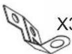
- Use the connection part(MM) and bolt M8X10(LL) to connect the Cylinder Housing(F) to the base(G), and fix it with bolt M8X16(BB).
Hardware Used

Bolt M8X16

X3

Bolt M6X10

X3

Connection par

X3

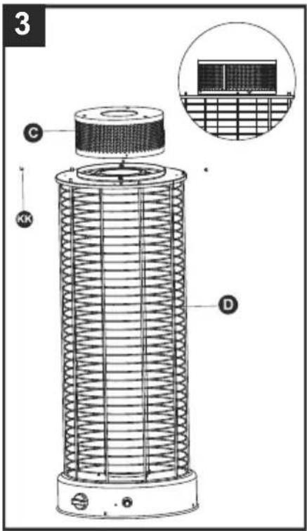
- Use screws 3/16"(KK) to connect the Top mesh(C) and burner assembly(D).
Hardware Used

Screws3/16"

X4
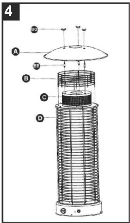
- First insert the Protective guard(B) into the top of the burner assembly(D), reflector(A) and Top mesh(C) with Reflector spacers(EE) and wing nuts(GG).
Hardware Used

Reflector spacers
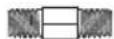
X6

Wing nuts

X6
- Connect the assembled upper and lower parts, connect the burner assembly(D) and the Cylinder Housing(F) with bolts M5X10(HH) and nuts M5(II).
Hardware Used

Bolt M5X10

X4

Nuts M5

X4

- Attach regulator to gas line and tank.
• Fit the gas regulator rubber hose with the end thread of
• inlet gas steel pipe and tighten the nut.
- Connect the regulator with the LPG gas tank in counter-clockwise direction and tighten it by adjustable wrench. • Put LPG gas tank into stand.

natural_image
Technical line drawing of a mechanical assembly with no visible text or symbols
natural_image
Technical line drawing of two mechanical devices with no visible text or symbols- Do not store a spare LPG gas cylinder under or near this appliance; • Never fill the cylinder beyond 80 percent full;
- Place the dust cap on the cylinder valve outlet whenever the cylinder is not in use. only install the type of dust cap on the cylinder valve that is provided with the cylinder valve. Other type of caps or plugs may result in leakage of propane.
PROBLEMS CHECK LIST
| PROBLEMS PROBABLE CAUSES SOLUTIONS | ||
| Pilot will not light | Gas valve may be OFF | Turn the gas valve ON |
| lank fuel empty | Refill LPG tank | |
| Opening blocked | Clean or replace opening | |
| Air in supply system | Purge air from lines | |
| Loose connection | Check all fittings | |
| Battery not fit in | Insert battery | |
| Pilot will not stay on | Debris around pilot | Clean dirty area |
| Loose connections | Tighten connections | |
| Thermocouple bad | Replace thermocouple | |
| Gas leak in line | Check connections | |
| Lack of fuel pressure | Tank near empty. Refill LPG tank. | |
| Anti tilt switch loose/faulty | Reconnect/replace anti tilt switch | |
| Burner will not light | Pressure is low | Tank near empty. Refill LPG tank. |
| Opening blocked | Remove and clean | |
| Control not on | Turn valve to ON | |
| Thermocouple bad | Replace thermocouple | |
| Pilot light assembly bent | Place pilot properly | |
| Not in correct location | Position properly and retry | |
If you have any other issues, please contact your supplier or distributor. Please do not attempt to modify the heater in any way or form.
SERVICE AND MAINTENANCE INFORMATION
If the pilot heater fails to operate correctly, contact place of purchase or their authorised service agent for advice and service.
DO NOT ATTEMPT REPAIRS YOURSELF.
Periodic maintenance should performed at intervals not exceeding 6 months or faults exist, (i.e.) flame burning abnormality or burner discolouration. Flame bnon discolouration is generally a sign of gas supply blockage or blocked burner ports.
To clean the burner ports, remove the reflector assembly by removing the three nuts at the top of the reflector. The mesh screen may then be extracted by removing the four retention screws at the base of the mesh screen and four screws at the top of the screen. Remove the two screws retaining the burner assembly, Rotate the burner assembly slightly then remove the burner assembly upwards.
Care should always be taken to avoid damage to the gas piping and Piezo ignition lead. The burner and mesh screen may than be deaned by compressed air. Assembly is a reversal of the above procedure. If the pilot is blocked by debris, spider webs etc. the pilot flame may be small and the flame failure device may have not heated up enough for the main burner to come on. If this happens it will be necessary to clean the pilot and its gas tube.
To dean the pilot, remove the burner and pilot cover as detailed above, Inspect the pilot injector and tubing for blockage. If obstoicted dean with compressed air. Clean the flame failure device. Assembly is a reversal of the above procedure.


- PER LA VOSTRA SICUREZZA E PER UN CORRETTO USO DELL'APPARECCHIO LEGGERE ATTENTAMENTE E CONSERVARE QUESTO MANUALE
- ATTENZIONE
- PRIMA DI METTERE IN FUNZIONE QUESTA STUFA, LEGGERE LE SEGUENTI RACCOMANDAZIONI PER LA SICUREZZA.
- CONSERVAZIONE
- FOR YOUR SAFETY PLEASE READ CAREFULLY AND KEEP THIS INSTRUCTION OF USE
- WARNING
- PLEASE READ THE FOLLOWING SAFETY ADVICE PRIOR TO THE OPERATION OF THIS HEATER If you smell gas:
- Read all of these instructions before installation and use.
- SAFETY PRECAUTIONS
- HEATER STAND AND LOCATION
- GAS REQUIREMENTS
- LEAKAGE TEST
- FUEL GAS ODOR
- ANY GAS ODOR IS YOUR SIGNAL TO GO INTO IMMEDIATE ACTION.
- TO TURN ON THE HEATER
- Note:
- TO TURN THE HEATER OFF
- STORAGE
- CLEANING AND CARE
- ASSEMBLY INSTRUCTIONS
- Hardware Used
- SERVICE AND MAINTENANCE INFORMATION
- DO NOT ATTEMPT REPAIRS YOURSELF.
Brand : DCG
Model : SA9500
Category : Heating