AquaPure PLC1400 - Water pump Jandy - Free user manual and instructions
Find the device manual for free AquaPure PLC1400 Jandy in PDF.

| Product Type | Water Pump (Pool Pump) |
| Brand | Jandy |
| Model | AquaPure PLC1400 |
| Flow Rate | 1400 Gallons Per Hour (GPH) |
| Voltage | 230 V / 115 V (Dual Voltage) |
| Power | 1.5 HP |
| Speed | Single Speed |
| Dimensions (L x W x H) | 24 in x 12 in x 14 in |
| Weight | 40 lbs |
| Material | Thermoplastic Housing |
| Application | In-Ground Pools, Spas |
| Priming | Self-Priming |
| Maximum Head | 45 ft |
| Inlet/Outlet Size | 2 inch NPT |
| Motor Type | Totally Enclosed Fan Cooled (TEFC) |
| Thermal Protection | Automatic Reset |
| Bearings | Sealed Ball Bearings |
| Impeller | Corrosion-Resistant Plastic |
| Maintenance | Periodic cleaning of strainer basket; replace seal if leaking |
| Safety Features | Grounding Lug, Thermal Overload Protection |
| Spare Parts | Motor, Seal Kit, Impeller, Diffuser, Strainer Cover |
| Warranty | 1 Year Limited (Motor) / 90 Days Labor |
Frequently Asked Questions - AquaPure PLC1400 Jandy
User questions about AquaPure PLC1400 Jandy
0 question about this device. Answer the ones you know or ask your own.
Ask a new question about this device
Download the instructions for your Water pump in PDF format for free! Find your manual AquaPure PLC1400 - Jandy and take your electronic device back in hand. On this page are published all the documents necessary for the use of your device. AquaPure PLC1400 by Jandy.
USER MANUAL AquaPure PLC1400 Jandy
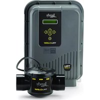
Water Purification System Power Center and Cell Kit
natural_image
Product photo of a AquaLink water spray bottle and packaging box (no visible text or symbols on main subject)
natural_image
Product photo of AquaPure brand water spray bottle and packaging (no visible text or symbols on main subject)Models:
APUREM
PLC700
PLC1400

WARNING
If these instructions are not followed exactly, a fire or explosion may result, causing property damage, personal injury, or death.
FOR YOUR SAFETY: This product must be installed and serviced by a contractor who is licensed and qualified in pool equipment by the jurisdiction in which the product will be installed where such state or local requirements exists. In the event no such state or local requirement exists, the installer or maintainer must be a professional with sufficient experience in pool equipment installation and maintenance so that all of the instructions in this manual can be followed exactly. Before installing this product, read and follow all warning notices and instructions that accompany this product. Failure to follow warning notices and instructions may result in property damage, personal injury, or death. Improper installation and/or operation will void the warranty.
Table of Contents
Section 1. Important Safety Instructions.....5
Section 2. System Description......8
2.1 Product Description 8
2.2 Electrical Specifications....9
Section 3. Installation Instructions....12
3.1 Materials and Tools....12
3.2 Plumbing Configurations....13
3.2.1 Recommended Electrolytic Cell and Sensor Orientation....13
3.2.2 Recommended Plumbing Configuration ....14
3.3 Installing AquaPure and PureLink Control/Power Centers....15
3.4 Earth Bonding (Grounding)....16
3.5 Model Configuration....17
3.6 Installation of the Chlorine Generator User Interface on an AquaLink® RS or PDA Bezel .... 17
3.7 Installing the Electrolytic Cell and Flow/Temp/Salinity Sensor....18
3.7.1 New Installation....18
3.7.2 Replacement of Existing 3-Port Cell (Universal or 2" PVC Unions)....19
3.7.3 Replacement of old 2-Port (Square) Cell with new 3-Port Cell....20
3.8 Connection of Chlorine Generator Electronics to an AquaLink Control System 24
3.8.1 Wiring AquaPure Control Center to an AquaLink Power Center ....24
3.9 Operation of External Control/ORP Control Board 26
Section 4. Pool Water Preparation....27
4.1 Determining Pool Size (Liters of Water in Your Pool) 27
4.2 Determining Pool Size (Gallons of Water in Your Pool) 27
4.3 Selecting Model Size 27
4.5 Optimum Pool Water Conditions .....29
4.6 Chlorine Testing 29
4.7 Salt (NaCl sodium chloride) 30
4.7.1 When to Add Salt? 30
4.7.2 What Type of Salt to Use? 30
4.7.3 How Much Salt to Use? 30
4.7.4 How to Add Salt to the Pool? .....30
Section 5. Operating Instructions....32
5.1 User Interface Controls....32
5.2 Reading the Display....33
5.3 Operation 35
5.4 Startup 36
5.4.1 Shocking 36
5.4.2 Apply Power....36
5.5 Operating in Winter 36
5.6 Recommendations....37
Section 6. User Maintenance Instructions ... 38
6.1 Daily 38
6.2 Monthly 38
6.3 Electrolytic Cell Cleaning - As Needed .... 38
6.4 Flow/Temp/Salinity Sensor Cleaning 39
6.5 Winterizing....40
Section 7. Troubleshooting .... 41
7.1 Problems and Corrective Action 41
7.3 Level 2 Service Codes....44
Section 8. Temperature Conversion ..... 46
Section 9. AquaPure and PureLink Exploded Views and Replacement Kits.....47
9.1 AquaPure and PureLink Control/Power Center Replacement Parts 47
9.2 3-Port Electrolytic Cell and Sensor Replacement Parts with Universal Unions (2"-2½")......49
9.3 3-Port Electrolytic Cell and Sensor Replacement Parts (2" PVC Unions) 50
Figures
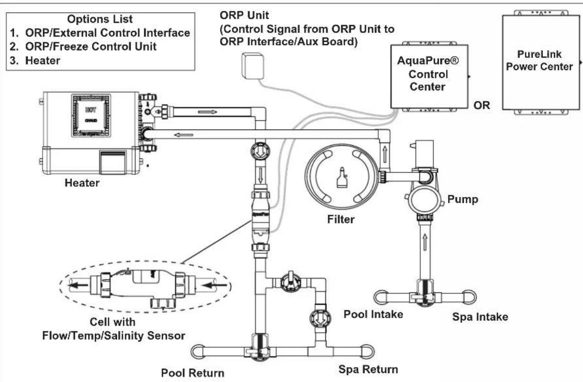
Figure 1. Typical AquaPure and PureLink Installation Example With Options.... 8
Figure 2a. Wiring Diagram for the PureLink ^TM System with a 240 VAC Filter Pump .... 10
Figure 2b. Wiring Diagram for the PureLink System with a 120 VAC Filter Pump ...... 11
Figure 2c. Wiring Diagram for the AquaPure System .... 12
Figure 3. Chlorine Generator Cell and Sensor Orientation with Flow Direction ..... 13
Figure 4. Recommended Plumbing Configuration for Pool/Spa Combination Systems ..... 14
Figure 5. Recommended Plumbing Configuration for Pool or Dual Equipment Systems .... 14
Figure 6. Removing the Control/Power Center Mounting Brackets from Shipping Position .... 15
Figure 7. Mark Holes using Control/Power Center Mounting Bracket .... 15
Figure 8. Reinstall Mounting Brackets on Control/Power Center....16
Figure 9. Chlorine Generator Power Interface Board....17
Figure 10. Installation of the User Interface ..... 17
Figure 11. Cell Installation and Flow/Temp/Salinity Sensor....22
Figure 12. Pipe Cutout ...... 23
Figure 13. Pipe Cutout (Option 3 - Replace 2-Port Cell and Piping and treat as New Installation)....23
Figure 14. Power Connection between AquaPure Control Center and AquaLink Power Center 24
Figure 15. Communication Connection between AquaPure Control Center and AquaLink Control System....24
Figure 16a. Wiring a PureLink Control System Network....25
Figure 16b. Wiring a PDA Control System Network.. 25
Figure 17. Movable ORP Jumper J14 ...... 26
Figure 18. User Interface....32
Figure 19. Spool Piece Location .... 40
Figure 20a. AquaPure Control Center....46
Figure 20b. PureLink Power Center, 6614AP......47
Figure 20c. PureLink Power Center, 6613AP......47
Figure 21. 3-Port Electrolytic Cell and Sensor Exploded View (Universal Unions)....48
Figure 22. 3-Port Spool Exploded View .....48
Figure 23. 3-Port Electrolytic Cell and Sensor Exploded View (2" PVC Unions) ..... 49
Figure 24. 3-Port Spool Exploded View....49
Tables
Table 1. Option Selection Tool....20
Table 2. Approximate Kilograms (Pounds) of Salt Needed to Obtain 3.0 gpl (3,000 PPM) in Pool....31
Section 1. Important Safety Instructions
READ AND FOLLOW ALL INSTRUCTIONS
All electrical work must be performed by a licensed electrician and conform to all national, state, and local codes. When installing and using this electrical equipment, basic safety precautions should always be followed, including the following:
| ⚠️ DANGERTo reduce the risk of injury, do not remove the suction fittings of your spa or hot tub. Never operate a spa or hot tub if the suction fittings are broken or missing. Never replace a suction fitting with one rated less than the flow rate marked on the equipment assembly. |
| ⚠️ WARNINGWhen mixing acid with water, ALWAYS ADD ACID TO WATER. NEVER ADD WATER TO ACID. |
| ⚠️ WARNINGTo reduce the risk of electric shock, fire or injury, service should only be attempted by a qualified Pool Service Professional. |
| ⚠️ WARNINGDo not operate electrolytic cell without proper flow or water circulation. A buildup of flammable gases would result in hazardous conditions. |
| ⚠️ WARNINGRISK OF ELECTRIC SHOCK, FIRE, PERSONAL INJURY, OR DEATH.Installation must be done in accordance with the National Electric Code (NEC, NFPA-70) and/or any other applicable local and national installation codes.A green colored terminal (or a wire connector marked “G”, “GR”, “Ground” or “Grounding”) is provided within the terminal compartment. To reduce risk of electric shock, connect this terminal or connector to the grounding terminal of your electric service or supply panel with a conductor equivalent in size to the circuit conductors supplying this equipment.Power supply must be interconnected with Pool Pump motor power source. This insures the chlorinator and pool pump will turn on and off together.Use of chemicals other than those recommended may be hazardous. Follow the Chemical Manufacturers Instructions.If the Flow/Temp/Salinity sensor is not installed in the electrolytic cell then it is recommended that it is installed in the same piping as the cell, up stream from the cell, and without any valves or diverters between them.The Flow/Temp/Salinity sensor must be mounted as shown in Figure 3. |
| ⚠️ WARNINGTo Reduce the Risk of Injury -a) The water in a spa should never exceed 104°F (40°C). Water temperatures between 100°F (38°C) and 104°F (40°C) are considered safe for a healthy adult. Lower water temperatures are recommended for young children and when spa use exceeds 10 minutes.b) Since excessive water temperatures have a high potential for causing fetal damage during the early months of pregnancy, pregnant or possibly pregnant women should limit spa water temperatures to 100°F (38°C).c) Before entering a spa or hot tub, the user should measure the water temperature with an accurate thermometer since the tolerance of water temperature-regulating devices varies.d) The use of alcohol, drugs, or medication before or during spa or hot tub use may lead to unconsciousness with the possibility of drowning.e) Obese persons and persons with a history of heart disease, low or high blood pressure, circulatory system problems, or diabetes should consult a physician before using a spa.f) Persons using medication should consult a physician before using a spa or hot tub since some medication may induce drowsiness while other medication may affect heart rate, blood pressure, and circulation. |
WARNING
Prolonged immersion in hot water may induce hyperthermia. Hyperthermia occurs when the internal temperature of the body reaches a level several degrees above the normal body temperature of 98.6^ F ( 37^ C). The symptoms of hyperthermia include dizziness, fainting, drowsiness, lethargy, and an increase in the internal temperature of the body. The effects of hyperthermia include: 1) unawareness of impending danger; 2) failure to perceive heat; 3) failure to recognize the need to exit spa; 4) physical inability to exit spa; 5) fetal damage in pregnant women; 6) unconsciousness resulting in a danger of drowning.
WARNING
Risk of electric shock - Install the power center at least five (5) feet (1.52m) from the inside wall of the pool and/or hot tub using non-metallic plumbing. Canadian installations must be at least three (3) meters from the water. Children should not use spas or hot tubs without adult supervision.
Do not use spas or hot tubs unless all suction guards are installed to prevent body and hair entrapment. People using medications and/or having an adverse medical history should consult a physician before using a spa or hot tub.
WARNING
People with infectious diseases should not use a spa or hot tub.
To avoid injury, exercise care when entering or exiting the spa or hot tub.
Do not use drugs or alcohol before or during the use of a spa or hot tub to avoid unconsciousness and possible drowning. Pregnant or possibly pregnant women should consult a physician before using a spa or hot tub. Water temperature in excess of 100^ (38^) may be injurious and hazardous to your health. Before entering a spa or hot tub measure the water temperature with an accurate thermometer. Do not use a spa or hot tub immediately following strenuous exercise. Prolonged immersion in a spa or hot tub may be injurious to your health. Do not permit any electric appliance (such as a light, telephone, radio, or television) within 5 feet (1.52m) of a spa or hot tub. The use of alcohol, drugs or medication can greatly increase the risk of fatal hyperthermia in hot tubs and spas.
WARNING
To avoid injury ensure that you use this control system to control only packaged pool/spa heaters which have built-in operating and high limit controls to limit water temperature for pool/spa applications. This device should not be relied upon as a safety limit control.
CAUTION
A terminal bar marked "GROUND" is provided within the power center. To reduce the risk of electrical shock, connect this terminal bar to the grounding terminal of your electric service or supply panel with a continuous copper conductor having green insulation and one that is equivalent in size to the circuit conductors supplying this equipment, but no smaller than no. 12 AWG (3.3mm). In addition, a second wire connector should be bonded with a no. 8 AWG (4.115mm) copper wire to any metal ladders, water pipes, or other metal within five (5) feet (1.52m) of the pool, spa, or hot tub.

Attention installer: Install to provide drainage of compartment for electrical components.
CAUTION
It is important to note that certain materials used in and around swimming pools and spas may not be compatible with chemicals commonly used to purify pool and spa water (e.g. acids, chlorine, salt, stabilizers, etc.).
As such, Zodiac Pool Systems LLC does not warrant or guarantee that the chlorinated water generated by the salt water chlorinator will not damage or destroy certain types of plants, decking, coping and other materials in and around your pool and/or spa. Before selecting materials to be used in and around your pool and/or spa, please discuss all options with your contractor to assess the compatibility of such materials and chemicals.
Some helpful considerations may include:
- Choosing plants that can withstand splash out of pool water containing chlorine and/or salt and other water purification chemicals.
- All metal components used in and around a pool should be of a high grade, quality stainless steel.
- Careful selection of masonry products. The porosity and hardness of natural stones varies greatly. Therefore we recommend you consult with your builder or stone contractor on the best choice for stone materials around your pool or spa.
- Sealing all masonry products. Professionals in the stone industry specify that even natural stone, especially when used outdoors, be sealed to prevent weathering, staining, and premature degradation. Consult with your stone or deck contractor for the proper sealer for the masonry products you have selected to use around your pool or spa.
- For the optimal results, sealers should be reapplied on a regular basis. Reapply the protective sealer on a schedule per the manufacturer's instructions.
WARNING
The power pack must be interlocked/interconnected with the pool pump motor power source to ensure that the chlorinator only operates when the pool pump is operating. The flow sensor feature of the chlorinator cell is intended to be used as a backup only and should not be used as the sole source of flow detection.
SAVE THESE INSTRUCTIONS
Section 2. System Description
flowchart
graph TD
    A["Heater"] --> B["Filter"]
    B --> C["AquaPure® Control Center"]
    C --> D["PureLink Power Center"]
    D --> E["Pump"]
    E --> F["Pool Intake"]
    F --> G["Spa Intake"]
    G --> H["Pool Return"]
    H --> I["Cell with Flow/Temp/Salinity Sensor"]
    I --> J["Options List"]
    style A fill:#f9f,stroke:#333
    style B fill:#ccf,stroke:#333
    style C fill:#cfc,stroke:#333
    style D fill:#fcc,stroke:#333
    style E fill:#cff,stroke:#333
    style F fill:#ffc,stroke:#333
    style G fill:#cfc,stroke:#333
    style H fill:#fcc,stroke:#333
    style I fill:#ffc,stroke:#333
    style J fill:#fcc,stroke:#333
Figure 1. Typical AquaPure and PureLink Installation Example With Options

ATTENTION INSTALLER: Various application notes (including more detailed instructions) are available from the Dealer covering installation, operation, maintenance, and plumbing of the chlorinator system.
2.1 Product Description
The AquaPure and PureLink systems use a process known as electrolysis to produce sodium hypochlorite (liquid chlorine) from a low concentration of salt added to the pool water. Hypochlorite kills bacteria, oxidizes organic material, and kills algae then reverts back to salt. The system then reuses the salt and the process starts over again. The systems are comprised of the following components:
AquaPure Control Center (for stand alone systems)
- The AquaPure control center converts AC power into low voltage DC current which is required by the cell to perform the electrolysis.
- The LCD display on the user interface offers monitoring of chlorine production, cell modes, salinity level, temperature, water flow and diagnostics.
- The control center is connected with the pool circulation pump electrical source so that the electrolytic cell can only operate when the pool pump is on. An optional pool pump timer can be utilized to help control this function. The flow portion of the Flow/Temp/Salinity Sensor is a backup device only.
PureLink Power Center (for PureLink systems)
- The PureLink ^TM system integrates a salt water chlorinator control system and power center for use with AquaLink Pool/Spa Automation systems (not including AquaLink Z4).
- The LCD display on the user interface offers monitoring of chlorine production, cell modes, salinity level, temperature, water flow and diagnostics.
- The chlorine generator electronics inside the power center are connected with the pool circulation pump electrical source so that the electrolytic cell only operates when the pool pump is on. The flow portion of the Flow/Temp/Salinity Sensor is a backup device only.
Electrolytic Cell
The electrolytic cell contains bipolar electrodes which perform the electrolysis and produce chlorine when energized with DC current. Chlorine is generated as pool water containing salt passes through the cell. The chlorine production can be varied by either adjusting the chlorine production level on the power center or by varying the number of hours the unit is on each day. The system automatically cleans the cell's electrode plates once every 3 hours by reversing the polarity of the electrical current. Whether the system is in forward or reverse, it is still producing chlorine.
Flow/ Temperature/ Salinity/Sensor
The flow portion of the flow/temp/salinity sensor detects if there is adequate water flow through the cell. The salinity portion of the flow/temp/salinity sensor detects the level of salt in the pool water. This salt level is displayed in grams per liter (GPL)* on the user interface liquid crystal display (LCD) whenever the salinity button is pressed. This eliminates the need to manually test the salinity of the pool water. The pool temperature is displayed by pressing the Temperature button.
*1 gram per liter (GPL) = 1000 ppm (parts per million)
2.2 Electrical Specifications
700 Model 1400 Model
Input: 120 VAC, 50/60 Hz, 1.5 AMPS 240 VAC, 50/60 Hz, 0.75 AMPS
Input: 120 VAC, 50/60 Hz, 2.5 AMPS 240 VAC, 50/60 Hz, 1.25 AMPS
Output: 27 VDC @ 3 AMPS maximum Output: 27 VDC @ 6 AMPS maximum
Chlorine: 0.625 lb. / 24 Hr. (283 gm / 24 Hr.) Chlorine: 1.25 lb. / 24 Hr. (567 gm / 24 Hr.)
External ORP/External Control Connector Control: AquaLink RS485 Connector
External ORP/External Control Connector Control: AquaLink RS485 Connector
CAUTION
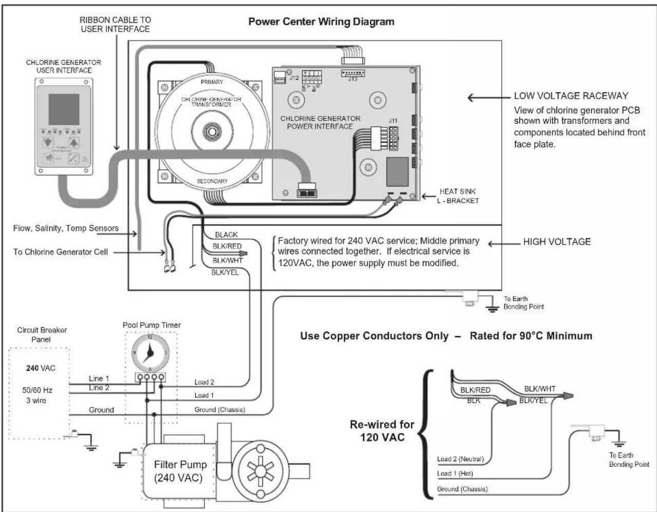
The electronics for the salt water chlorinator are factory wired for 240 VAC service. If the available electrical service is 120 VAC then the power supply wiring must be changed to operate on 120 VAC as shown in Figure 2b.
The chlorinator's electronics are powered from the LOAD SIDE of the pool circulation pump relay; therefore, if the available electrical service is 120 VAC, then the pump must also be wired for 120 VAC.
text_image
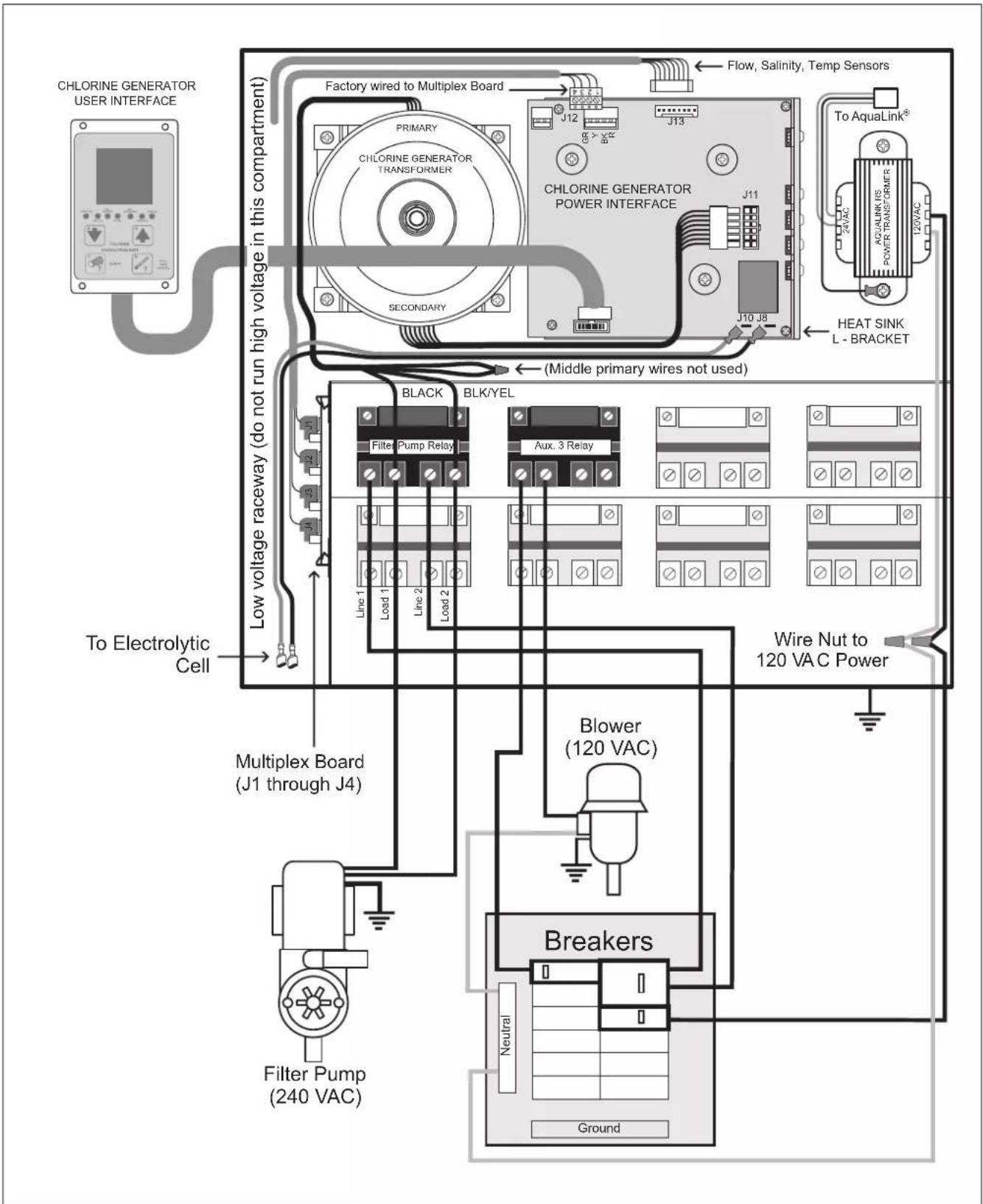
CHLORINE GENERATOR USER INTERFACE Factory wired to Multiplex Board Primary CHLORINE GENERATOR TRANSFORMER SECONDARY LOW voltage raceway (do not run high voltage in this compartment) Black BLK/YEL Filter Pump Relay Line 1 Load 1 Line 2 Load 2 To Electrolytic Cell Multiplex Board (J1 through J4) Flow, Salinity, Temp Sensors J12 J13 CHLORINE GENERATOR POWER INTERFACE J11 J10 J8 (Middle primary wires not used) Aux. 3 Relay Line 2 Line 1 Line 2 Line 1 Line 1 Line 2 Line 1 Line 2 Line 1 Line 2 Line 1 Line 2 Line 1 Line 2 Line 1 Line 2 Line 1 Line 2 Line 1 Line 2 Line 1 Line 2 Line 1 Line 2 Line 1 Line 2 Line 1 Line 2 Line 1 Line 2 Line 2 Line 1 Line 2 Line 1 Line 2 Line 1 Line 2 Line 1 Line 2 Line 1 Line 2 Line 1 Line 2 Line 1 Line 2 Line 1 Line 2 Line 1 Line 2 Line 1 Line 2 Line 1 Line 2 Line 1 Line 1 Line 2 Line 1 Line 2 Line 1 Line 2 Line 1 Line 2 Line 1 Line 2 Line 1 Line 2 Line 1 Line 2 Line 1 Line 2 Line 1 Line 2 Line 1 Line 2 Line 2 Line 1 Line 2 Line 1 Line 1 Line 2 Line 1 Line 2 Line 1 Line 2 Line 1 Line 2 Line 1 Line 2 Line 1 Line 2 Line 1 Line 2 Line 1 Line 2 Line 1 Line 2 Line 1 Line 2 Line 0 A/A B C D E F G H I J K L M N O P Q R S T U V W X Y Z X U V W X Y Z X U V W X Y Z X U V W X Y Z X U V W X Y Z X U V W X Y Z X U V W X Y Z X U V W X Y Z X U V W X Y Z X U V W X Y Z X U V W X Y Z X U V W X Y Z X U V W X Y Z X U V W X Y Z X U V W X Y Z X U U V W X Y Z X U V W X Y Z X U V W X Y Z X U V W X Y Z X U V W X Y Z X U V W X Y Z X U V W X Y Z X U V W X Y Z X U V W X Y Z X U V W X Y Z X U V W X Y Z X U V W X Y Z X U V W X Y Z X U V W X Y Z X UFigure 2a. Wiring Diagram for the PureLink ^TM System with a 240 VAC Filter Pump
text_image
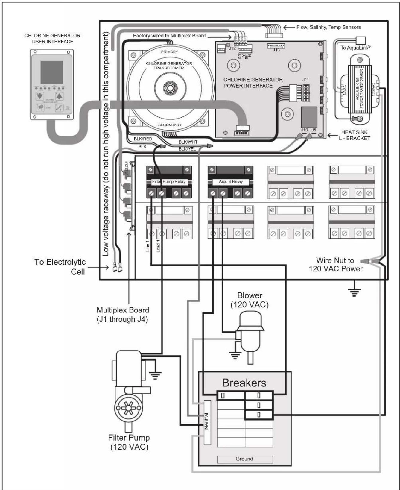
CHLORINE GENERATOR USER INTERFACE Factory wired to Multiplex Board Primary CHLORINE GENERATOR TRANSFORMER SECONDARY BLK/RED BLK BLK/WHT BLK/YEL LOW voltage raceway (do not run high voltage in this compartment) To Electrolytic Cell Multiplex Board (J1 through J4) Filter Pump (120 VAC) Flow, Salinity, Temp Sensors J12 J13 J11 J10 J8 Heat SINK L - BRACKET Line 1 Load 1 Filler Pump Relay Aux. 3 Relay Blower (120 VAC) Breakers Neutral GroundFigure 2b. Wiring Diagram for the PureLink ^TM System with a 120 VAC Filter Pump
text_image
RIBBON CABLE TO USER INTERFACE Power Center Wiring Diagram CHLORINE GENERATOR USER INTERFACE PRIMARY CHLORINE GENERATOR TRANSFORMER J12 J13 CHLORINE GENERATOR POWER INTERFACE J11 SECONDARY HEAT SINK L - BRACKET LOW VOLTAGE RACEWAY View of chlorine generator PCB shown with transformers and components located behind front face plate. Flow, Salinity, Temp Sensors To Chlorine Generator Cell BLACK BLK/RED BLK/WHT BLK/YEL FACTORY wired for 240 VAC service; Middle primary wires connected together. If electrical service is 120VAC, the power supply must be modified. HIGH VOLTAGE To Earth Bonding Point Circuit Breaker Panel 240 VAC 50/60 Hz 3 wire Pool Pump Timer Line 1 Line 2 Load 2 Load 1 Ground Ground (Chassis) Filter Pump (240 VAC) Use Copper Conductors Only – Rated for 90°C Minimum Re-wired for 120 VAC BLK/RED BLK/WHT BLK/YEL Load 2 (Neutral) Load 1 (Hot) Ground (Chassis) To Earth Bonding PointFigure 2c. Wiring Diagram for the AquaPure ^® System
WARNING
The power pack must be interlocked/interconnected with the pool pump motor power source to ensure that the chlorinator only operates when the pool pump is operating. The flow sensor feature of the chlorinator cell is intended to be used as a backup only and should not be used as the sole source of flow detection.
Section 3. Installation Instructions
3.1 Materials and Tools
NOTE Salt not included. See Section 4, Pool Water Preparation.
| Installation Materials Furnished | PureLinkTM Integrated Power Center (in lieu pf AquaPure control center)(1 ea.) PureLink power center (Standard or Breaker)(2 ea.) Wire Nuts(1 ea.) Installation Template |
| PLC700 / PLC1400 Cell Kits(1 ea.) Electrolytic Cell with 2"-2 12 " Universal Unions(1 ea.) Sensor with 16 ft (4.88m) Cable and O-ring(1 ea.) Universal Union Nut(1 ea.) 16 ft (4.88 m) DC Power Cord(1 ea.) Strain Relief(1 ea.) Owner's Manual - Warranty InformationAquaPure Control Center (PureLinkTM not used)(1 ea.) AquaPure Control Center(2 ea.) Wire Nuts(1 ea.) Installation Template | Tools Needed for InstallationTape MeasurePhillips & Flathead ScrewdriversPliersHacksawVoltmeter to determine line voltage of AC wiring to power supplyElectric Drill Motor and 1/4 " masonry drill bit for mounting power supply on block or stucco wallAn NSF®*approved All Purpose Cleaner PrimerAn NSF approved All Purpose Cement (such as Weld-Or® 794TM, 793TM) |
* NSF is a registered trademark of the NSF International.
WARNING
When using electrical products, basic precautions should always be followed, including the following:
- RISK OF ELECTRIC SHOCK WHICH CAN RESULT IN SERIOUS INJURY OR DEATH. Before attempting installation or service, ensure that all power to the device is disconnected/turned off at the circuit breaker.
- Grounding is required. The unit should be installed by a qualified service representative and should be properly grounded. (See Section 3.4, Earth Grounding).
• Install to permit access for servicing. - Read Section 1, Important Safety Instructions. Before attempting any electrical wiring, be sure to read and follow Safety Instructions. Wiring should only be attempted by a qualified professional.
3.2 Plumbing Configurations
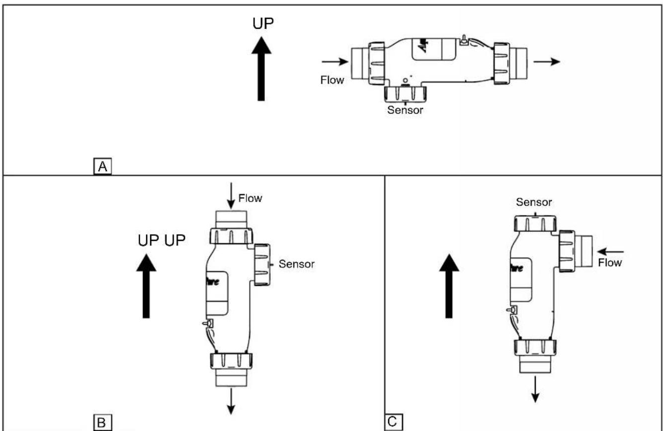
3.2.1 Recommended Electrolytic Cell and Sensor Orientation
Shown below are three (3) different cell and sensor orientations. The third port on the cell is designed for installation of the sensor and for quick viewing of the cell plates.
flowchart
graph TD
    subgraph_A["Top Panel"]
        A1["Sensor"] --> A2["Flow"]
        A2 --> A3["UP"]
        A3 --> A4["Sensor"]
    end
    subgraph_B["Bottom Panel"]
        B1["Sensor"] --> B2["Flow"]
        B2 --> B3["UP UP"]
        B3 --> B4["Sensor"]
    end
    A3 --> B3
    B3 --> C["Sensor"]
    style A3 fill:#f9f,stroke:#333
    style B3 fill:#ccf,stroke:#333
    style C fill:#cfc,stroke:#333
Figure 3. Chlorine Generator Cell and Sensor Orientation with Flow Direction
3.2.2 Recommended Plumbing Configuration
The preferred installation is that the cell and sensor are plumbed in the common line after (downstream) the heater. The sensor is designed to be plumbed into the 3-port cell. Figure 4 illustrates the recommended plumbing configuration, which results in the most reliable operation.
NOTE The AquaPure® and PureLink™ systems are powered from the LOAD SIDE of the pool circulation pump relay. This ensures that the cell only operates when the pool pump is energized. The flow sensor serves as a secondary means to ensure there is sufficient flow for the cell to operate.
flowchart
graph LR
    A["Heater"] --> B["Cell"]
    B --> C["Sensor"]
    C --> D["Control/Power Center"]
    D --> E["Pool Return"]
    E --> F["Spa Return"]
    F --> G["Spa Bypass for Spillover"]
    G --> H["JAWDY"]
Figure 4. Recommended Plumbing Configuration for Pool/Spa Combination Systems
flowchart
graph TD
    A["Heater"] --> B["Control/Power Center"]
    B --> C["Sensor"]
    C --> D["Pool Return"]
    D --> E["Cell"]
    E --> A
Figure 5. Recommended Plumbing Configuration for Pool or Dual Equipment Systems
3.3 Installing AquaPure and PureLink Control/Power Centers
NOTE The control/power center should be located at or near the equipment pad.

CAUTION
The control/power center is not to be considered as suitable for use as service equipment. Therefore, it is required to have the appropriate means of disconnection, circuit isolation, and/or branch circuit protection installed upstream of the power center.
- Locate the control/power center at least five (5) feet or more away from pool/spa and five (5) feet off the ground. All national, state, and local codes are applicable.
NOTE For Canadian installations, the control/power center must be at least three (3) meters (9.8 feet) away from the pool/spa and 1.5 meters (5 feet) above the ground. - The control/power center comes with two (2) full length, heavy duty mounting brackets fastened to the back of the power center during shipping. Remove the four (4) screws that are holding the two (2) brackets and the cardboard shipping cover in place (see Figure 6). Remove and discard the cardboard.
text_image
Remove the four (4) screws that secure the brackets to the Power Center during shipping Cardboard Shipping Cover Mounting Brackets (2) AquaPure Control Center PureLink Power CenterFigure 6. Removing the Control/Power Center Mounting Brackets from Shipping Position
- Using the top mounting bracket as a guide, mark three (3) holes on the mounting surface where the power center will ultimately reside (see Figure 7). Drill the holes in the mounting surface.
NOTE The three mounting holes are four inches (4") apart center to center.
NOTE Use heavy-weight screws. The power center with all available components installed can weigh up to 50 pounds.
text_image
Mark Ho 4" 4" Mounting BracketFigure 7. Mark Holes using Control/Power Center Mounting Bracket
- Reinstall the mounting brackets to the top and bottom of the back of the control/power center using the four (4) screws that were removed in Step 2. Ensure that the brackets are rotated from the original shipping position (see Figure 8).
text_image
Reinstall Mounting Brackets (Ensure to Rotate from Original Shipping Position)Figure 8. Reinstall Mounting Brackets on Conrol/Power Center
- Hang the control/power center on the surface using the three (3) holes drilled in Step 3. With the control/power center in place, mark three (3) holes for the bottom bracket mounting.
NOTE As with the top brackets, the bottom bracket requires three (3) mounting holes. The three (3) mounting holes are four inches (4") apart center to center.
-
Drill the holes and install the screws.
-
Level the control/power center and tighten all screws, ensuring that the control/power center is securely fastened to the mounting surface.
-
Check source voltage. (All units are factory wired for 240 VAC). In order to use on 120 VAC, the internal factory wiring of the power center must be changed. (See Figures 2b and 2c).
3.4 Earth Bonding (Grounding)
A solid, copper # 8 awg (8.4 mm ^2 ) wire is recommended for connecting the control/power center to a permanent earth ground connection that is acceptable to the local inspection authority. Refer to your local codes for the acceptable grounding wire gauge. Attach the bonding point located on bottom of the power center to a common earth bonding point. Do not use the control/power center as the common bonding point. Each piece of non-chlorinator related pool equipment requiring a ground should be bonded to the common, approved, earth bonding point.
3.5 Model Configuration
The chlorine generator Power Interface Board (PIB) is configured as a 1400 model by factory default. However, the Power Interface Board can be configured as a 700 model.
To configure the board as a 700 model, use cutting pliers to cut the JL1 jumper as shown in Figure 9.
text_image
Heat Sink L-Bracket Chlorine Generator Power Interface Board (PIB) Cut JL1 Jumper to configure board as Model AP700Figure 9. Chlorine Generator Power Interface Board (PIB)
3.6 Installation of the Chlorine Generator User Interface on an AquaLink® RS or PDA Bezel
- On the chlorine generator User Interface Board (UIB), connect one end of the ribbon cable to the 16-pin J1 connector as shown in Figure 10.
- Connect the other end of the ribbon cable to the 16-pin J1 connector on the Power Interface Board (PIB).
- Attach the chlorine generator User Interface Board (UIB) to the bezel using the four (4) screws provided.
text_image
J1 Connector, Chlorine Generator Power Interface Board Ribbon Cable J1 Connector, User Interface Screws (4)Figure 10. Installation of the User Interface
3.7 Installing the Electrolytic Cell and Flow/Temp/Salinity Sensor
Please choose one of the following instructions to either install or replace the cell and sensor assembly.
3.7.1 New Installation
3.7.2 Replacement of Existing 3-Port Cell
3.7.3 Replacement of 2-Port (square) Cell and Sensor Tee with 3-Port Cell
NOTE: Maximum operating Pressure is 345 kPa or 50 PSI.

WARNING
ATTENTION INSTALLER: If the flow/temp/salinity sensor is not installed properly, it may allow the electrolytic cell to operate without water flow. This would cause a buildup of flammable gases resulting in FIRE or EXPLOSION.
- Mount as shown in Figure 11. This will result in the most reliable operation.
• The flow/temp/salinity sensor must be mounted:
(1) In one of the available ports in the electrolytic cell
- Or -
(2) In the same line prior to the cell with no valves or diverters between the flow/temp/salinity sensor and cell.
- Anytime the flow/temp/salinity sensor is connected or disconnected and reconnected, the AC power to the unit must be turned off and back on (Cycle Power). If power is not cycled, unreliable operation of the flow/temp/salinity sensor will result.
3.7.1 New Installation
- Be sure pool pump is turned off.
- It is recommended that the flow/temp/salinity sensor and electrolytic cell be installed in the pool return line after the filter and heater. The cell can be installed in either a horizontal or a vertical position. See Figure 3.
- Position the flow/temp/salinity sensor and cell in the recommended position (see Figures 1, 3, 4 and 5).
- Locate a suitable section of pipe, approximately 17 inches (432 mm) long or follow the recommended plumbing diagrams as shown in Figures 4 and 5. The flow/temp/salinity sensor cable and cell DC cord must be able to reach from the power center to this section of pipe.
- Cut out a 13^-7/_8'' (352 mm) section of the 2'' (50 mm) pipe to insert the Cell. See Figure 12. Glue on unions and install cell.
- Install the flow/temp/salinity sensor into the 3-Port cell. See Figure 11.
- Install the strain relief provided with the electrolytic cell kit into the low voltage knock out. Feed the connector end of the flow/temp/salinity sensor cable through the DC cord strain relief fitting. Be certain the connector is clean and dry, then plug the cable into the connector on the power center printed circuit board as shown in Figures 2a, 2b, and 2c. (Do not pull Flow/Temp/Salinity Sensor cable too tight, allow a little slack).
- Plug the DC cord into the cell stud terminals protruding from the cell top. The DC cord can be plugged into the cell in either direction.

CAUTION
To avoid risk of damage to the equipment and possible injury, it is important to make sure the DC cable connector is fully seated on the cell stud terminals.
- Connect the DC cord to the power center. Feed the DC cord through the same strain relief fitting as the flow/temp/salinity sensor. Plug the DC cord into the two spade connectors of the wiring harness located in the low voltage raceway of the control/power center, see Figure 2a, 2b, and 2c. This wiring harness establishes the connection between the cell and the power interface PCB.
- Tighten strain relief fitting screws for the flow/temp/salinity sensor and the DC cord. Do not pull Flow/Temp/Salinity Sensor cable or DC Cord too tight. Allow a little slack for the cable inside of power center enclosure.

CAUTION
Do not over tighten the strain relief fitting. Over tightening can cause damage to the flow/temp/salinity sensor cable.
- Prior to reattaching front cover, check the wiring. Be sure the flow/temp/salinity sensor is plugged in. The DC cord should be plugged in. Also, check the AC wiring.
- Plug one end of the ribbon cable into the back of the user interface and the other end into the J1 connector on the power interface PCB (see Figures 2a, 2b, 2c, and 10).

WARNING
To avoid property damage, serious injury or death, do not operate the electrolytic cell without water circulation. A buildup of flammable gases can result in FIRE or EXPLOSION.
3.7.2 Replacement of Existing 3-Port Cell (Universal or 2" PVC Unions)
- Be sure pool pump is turned off.
- Unplug DC cable from existing cell. Disconnect the DC cord from the wiring harness as shown in Figure 2a, 2b, and 2c. Loosen the strain relief fitting that also contains the cable for flow/temp/salinity sensor. Pull the DC cord out through the strain relief.

CAUTION
Do not allow the DC Cord to pull too tightly on flow/temp/salinity sensor cable as it is being pulled through the strain relief. This may damage the flow/temp/salinity sensor cable and its connection to the printed circuit board.
- Remove flow/temp/salinity sensor from cell by unscrewing coupling nut on sensor port. The sensor should pull straight out after nut is removed.
- Remove old 3-port cell body by unscrewing coupling nuts on flow ports. The cell body will be free to pull out after nuts are clear of the threads.
- Replace existing union o-rings with new o-rings provided with cell kit.
- Install new cell and tighten coupling nuts.
- Install the flow/temp/salinity sensor into the available sensor port (See Figure 11).
- Plug the new DC cord provided with the cell kit, in either direction, into the cell stud terminals protruding from the cell top. Make sure that the plug is fully inserted and bottomed out on the housing.

CAUTION
To avoid risk of damage to the equipment and possible injury, it is important to make sure the DC cable connector is fully seated on the cell stud terminals.
- Connect the DC cord to the control center. Feed the DC cord through the same strain relief fitting as the flow/temp/salinity sensor. Plug the DC cord into the two spade connectors of the wiring harness as shown in Figures 2a, 2b, and 2c.

CAUTION
Do not bury the electrolytic cell DC cord or sensor cable directly in the ground. Direct burial can cause damage to an electrical cord/cable.
- Tighten strain relief fitting screws for the flow/temp/salinity sensor cable and the DC cord. Do not pull flow/temp/salinity sensor cable or DC Cord too tight. Allow a little cable slack inside of control center enclosure.

CAUTION
Do not over tighten the strain relief fitting. Over tightening can cause damage to the flow/temp/salinity sensor cable.
- Check the wiring prior to reattaching front cover. Be sure the flow/temp/salinity sensor is plugged in. The DC cord should be plugged in. Also, check the AC wiring.
- If disconnected, plug the ribbon cable into the J1 connectors the user interface and the Power Interface PCB (See Figures 2a, 2b, 2c, and 10).

WARNING
To avoid property damage, serious injury or death, do not operate the electrolytic cell without water circulation. A buildup of flammable gases can result in FIRE or EXPLOSION.
3.7.3 Replacement of old 2-Port (Square) Cell with new 3-Port Cell
- Be sure pool pump is turned off.
- Unplug DC cable from existing cell. Disconnect the DC cord from the wiring harness as shown in Figure 2a, 2b, and 2c. Loosen the strain relief fitting that also contains the cable for flow/temp/salinity sensor. Pull the DC cord out through the strain relief.

CAUTION
Do not allow the DC Cord to pull too tightly on flow/temp/salinity sensor cable as it is being pulled through the strain relief. This may damage the flow/temp/salinity sensor cable and its connection to the printed circuit board.
- Please choose one of the following options (See Table 1):
3a. Option 1 - Retain Existing Sensor in Threaded Tee
3b. Option 2 - Install New Sensor in 3rd Port of Cell (remove old sensor and plug tee)
3c. Option 3 - Replace Section of Piping (eliminate old cell and sensor fittings) and treat as New Installation
| 2-Port CellThread Size and Style | Option 1 Option 2 Option 3 | |
| 2" PVC Male (black) Yes Yes Yes | ||
| 1.5" ABS Female (White "Hayward®" Style) No No Yes |
Table 1. Option Selection Tool
3a. Option 1 - Retain Existing Sensor in Threaded Tee
a. Remove old 2-Port cell body by unscrewing coupling nuts on ports. The cell body will be free to pull out after nuts are clear of the threads.
b. Replace existing union o-rings with new o-rings provided with cell kit.
c. Install new cell and tighten coupling nuts.
NOTE 3-Port Cell and 2-Port cell are the same length. The new cell should fit without any need to modify existing plumbing.
d. Ensure that the 3rd port is sealed off with provided o-ring, plug and nut. Verify coupling nut is properly hand tightened.
e. Go to Step 4, below.
3b. Option 2 - Install New Sensor in 3rd Port of Cell (remove old sensor and plug tee)
a. Remove old flow/temp/salinity sensor by unscrewing it from the threaded tee.
b. Replace sensor with 1 12 " threaded plug.
c. Disconnect the flow/temp/salinity sensor from the Power Interface PCB as shown in Figure 2a, 2b, and 2c. Loosen the strain relief fitting that also contains the cable for the DC cord. Pull the flow/temp/salinity sensor cable out through the strain relief.
d. Remove old 2-port cell body by unscrewing coupling nuts on ports. The cell body will be free to pull out after nuts are clear of the threads.
e. Replace existing union o-rings with new o-rings provided with cell kit.
f. Install new cell and tighten coupling nuts.
NOTE 3-Port Cell and 2-Port cell are the same length. The new cell should fit without any need to modify existing plumbing.
g. Install the new flow/temp/salinity sensor into the 3-port cell (See Figure 11).
h. Feed the connector end of the flow/temp/salinity sensor cable through the DC cord strain relief fitting. Be certain the connector is clean and dry, then plug the cable into the connector on the Power Interface PCB as shown in Figure 2a, 2b, and 2c (Do not pull flow/temp/salinity sensor cable too tight, allow a little slack).
i. Go to Step 4, below.
3c. Option 3 - Replace Section of Piping (eliminate old cell and sensor fittings) and treat as New Installation.
a. Cut out section of pipe that contains cell, sensor, and fittings. Glue straight couplers or reducing coupler onto open ends of piping. Make sure to leave enough length to fit in new cell (see Figure 13).
b. Go to Step 1, Section 3.7.1. New Installation
- Plug the DC cord, in either direction, into the cell stud terminals protruding from the cell top. Make sure that the plug is fully inserted and bottomed out on the housing.

CAUTION
To avoid risk of damage to the equipment and possible injury, it is important to make sure the DC cable connector is fully seated on the cell stud terminals.
- Connect the DC cord to the control center. Feed the DC cord through the same strain relief fitting as the flow/temp/salinity sensor. Plug the DC cord as shown in Figure 2a, 2b, and 2c.
CAUTION
Do not bury the electrolytic cell DC cord or Sensor cable directly in the ground. Direct burial can cause damage to an electrical cord/cable.
-
Tighten strain relief fitting screws for the flow/temp/salinity sensor cable and the DC cord. Do not pull flow/temp/salinity sensor cable or DC Cord too tight. Allow a little cable slack inside of control center enclosure.
-
Check the wiring prior to reattaching front cover. Be sure the flow/temp/salinity sensor is plugged in. The DC cord should be plugged in. Also, check the AC wiring.
CAUTION
Do not over tighten the strain relief fitting. Over tightening can cause damage to the flow/temp/salinity sensor cable.
- If disconnected, plug the ribbon cable into the J1 connectors the user interface and the Power Interface PCB (See Figures 2a, 2b, 2c, and 10).
CAUTION
Do not operate the electrolytic cell without water circulation. A buildup of flammable gases can result in FIRE or EXPLOSION.
text_image
Salinity Studs Sometimes Not Covered Temperature Sensors Flow/Temp/Salinity Sensor Face must be clean at all times for proper operation DC Cord Plug is Connected to Terminal Studs* 2" x 2½" or 50mm Union O-Ring Seal 2 x 2½" or 50mm Tailpiece with Coupling Nut or Flow/Temp/Salinity Sensor O-ring and Union Nut * Ensure the DC Plug is properly and securely connected to the terminal studs of the cell.Figure 11. Cell Installation and Flow/Temp/Salinity Sensor
text_image
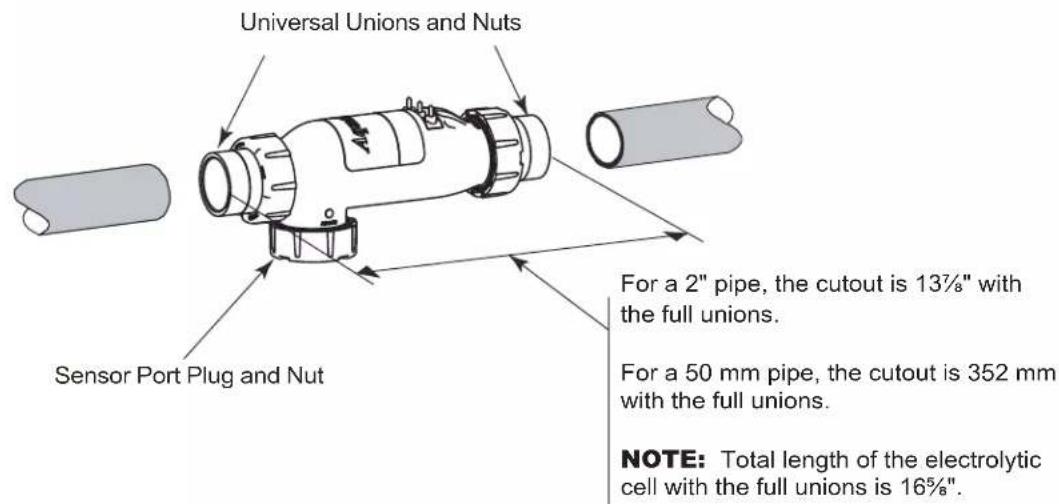
Universal Unions and Nuts Sensor Port Plug and Nut For a 2" pipe, the cutout is 13½" with the full unions. For a 50 mm pipe, the cutout is 352 mm with the full unions. NOTE: Total length of the electrolytic cell with the full unions is 16%".Figure 12. Pipe Cutout
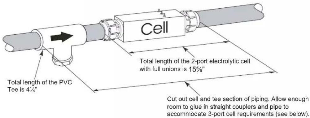
text_image
Cell Total length of the 2-port electrolytic cell with full unions is 15½" Total length of the PVC Tee is 4¼" Cut out cell and tee section of piping. Allow enough room to glue in straight couplers and pipe to accommodate 3-port cell requirements (see below).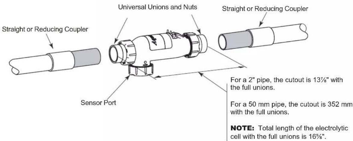
text_image
Straight or Reducing Coupler Universal Unions and Nuts Straight or Reducing Coupler Sensor Port For a 2" pipe, the cutout is 13½" with the full unions. For a 50 mm pipe, the cutout is 352 mm with the full unions. NOTE: Total length of the electrolytic cell with the full unions is 16¾".Figure 13. Pipe Cutout (Option 3 - Replace 2-Port Cell and Piping and treat as New Installation)
3.8 Connection of Chlorine Generator Electronics to an AquaLink® Control System
Many Jandy AquaLink Pool/Spa Automation systems can control the function of the chlorine generator (to varying degrees depending on the model). The chlorine generator user interface will display “JA” when any of the buttons are pressed while the AquaLink is controlling it. Adjustment of the chlorine production rate or Boost mode can be controlled from the menus of the AquaLink controller. Boost mode can also be activated from the chlorine generator user interface while the AquaLink is online. Refer to the Operation Manual included with the AquaLink Pool/Spa automation system for more information. The chlorine generator’s user interface will display temperature, salinity, service codes, and LED indicators as normal.
NOTE The AquaPure and PureLink chlorine generator electronics will communicate with AquaLink RS using firmware versions JJ or later.
3.8.1 Wiring AquaPure Control Center to an AquaLinkPower Center
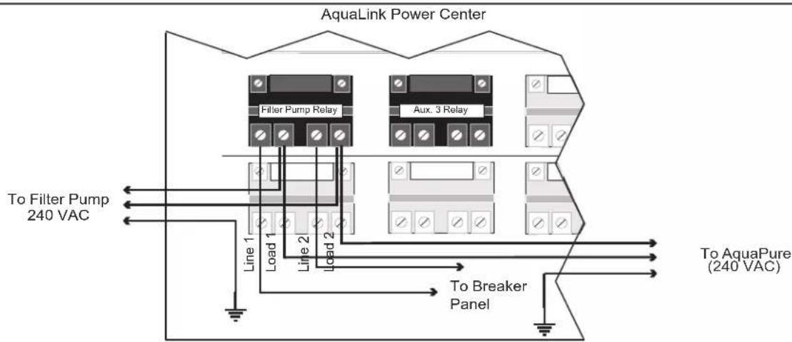
In the AquaLink power center enclosure, wire the AquaPure Control Center input power directly to the LOAD SIDE of the filter pump relay (see Figure 14).
flowchart
graph TD
    A["AquaLink Power Center"] --> B["Filter Pump Relay"]
    A --> C["Aux. 3 Relay"]
    B --> D["Line 1"]
    B --> E["Load 1"]
    B --> F["Line 2"]
    C --> G["Load 2"]
    C --> H["To Breaker Panel"]
    D --> I["To Filter Pump 240 VAC"]
    E --> J["To AquaPure (240 VAC)"]
    F --> K["To Breaker Panel"]
    G --> L["To Breaker Panel"]
Figure 14. Power Connection between AquaPure Control Center and AquaLink Power Center
The Jandy AquaLink and AquaPure use a four (4) wire connection to communicate. Any outdoor rated four (4) conductor cable, minimum 22 AWG, can be used. Locate the appropriate screw terminals on the circuit board according to Figure 15. Wire the AquaPure from the red 4-pin terminal bar to the AquaLink red 4-pin terminal bar (see Figure 15).
text_image
Red, 4-Pin Terminal Bar GRN YEL BLK RED 4 3 2 1 AquaLink RS Power Center Chlorine Generator Power Interface BoardNOTE The screw terminals are removable to aid in installation.
IMPORTANT Attach the wires to the like-numbered screw terminals on both the AquaPure and AquaLink.
Figure 15. Communication Connection between AquaPure Control Center and AquaLink Control System
3.8.2 Connection of PureLink Chlorine Generator Electronics to an AquaLink® Control System
The chlorine generator electronics in the PureLink Power Center and the AquaLink controller require a four (4) wire connection to communicate. Any outdoor rated four (4) conductor cable, minimum 22 AWG, can be used. Locate the appropriate screw terminals on the circuit board according to Figures 16. Wire the chlorine generator Power Interface Board (PIB) from the red 4-pin terminal bar to the AquaLink red 4-pin terminal bar (see Figure 16).
Referring to Figures 2a or 2b, wire the PureLink power center transformer to the load side of the filter pump relay.
text_image
Chlorine Generator Power Interface Board Red, 4-Pin Terminal Bar GRN YEL BLK RED PureLink Power CenterFigure 16. Wiring a PureLink Control System Network
3.9 Operation of External Control/ORP Control Board
An external device such as an ORP (Oxidation Reduction Potential) controller supplying 24 Volts AC can be used to control the output of the chlorine generator. The chlorine generator Power Interface Board (PIB) can be set up in the field to operate in two (2) different modes. The mode of operation is determined by the position of a movable jumper J14. See Figure 17 for location.
POS-1 (Wait at least one (1) minute after applying power. See note 1.)
With J14 jumper set to POS-1 and no voltage applied to the ORP 24 VAC connector J15, the chlorine generator works normally displaying the production rate of 0% to 100% on the display of the user interface.
When 24 Volts AC is applied to the ORP 24 VAC inputs, chlorine production will be disabled. The display of the user interface will then flash “EC” (external control). Once the 24 Volts AC input is removed the chlorine generator will return to normal operation. The “EC” will be replaced with the current production setting of 0% to 100%.
POS-2 (Wait at least one (1) minute after applying power. See note 1.)
Placing the jumper in POS-2 allows the chlorine generator to operate in the opposite way to POS-1. With 24 Volts AC applied to the ORP 24 VAC inputs, chlorine production will be enabled. The display of the user interface will display a production rate of 0% to 100%. When the 24 Volts AC is removed the display will flash “EC” every few seconds and chlorine production is disabled.
SUMMARY
| POSITION OF J14 24 VAC | 0 VAC | |
| POS-1 (default) | Unit OFF, displays EC | Unit ON, displays 0-100% |
| POS-2 | Unit ON, displays 0-100% | Unit OFF, displays EC |
Note 1 The unit samples the external control/ORP settings at the instant power is applied to the chlorine generator and will not respond to any changes during the first minute of operation. The unit may appear to be STUCK IN or STUCK OUT of "EC" mode. Wait several minutes until the unit has warmed up to verify the changes made to external control set-up.
Note 2 Multiple chlorine generators can be linked together to be controlled with one ORP controller without the use of external relays and transformers. Contact the factory for more information.
text_image
ORP Connector J15 R0474300 ORP Jumper J14 Wires to the external ORP Controller ORP POS-2 POS-1 J14 BUZZER OFF- ON - Chlorine Generator Power Interface BoardFigure 17. Movable ORP Jumper J14
Section 4. Pool Water Preparation

ATTENTION INSTALLER: Various application notes (including more detailed instructions) are available from the Dealer covering installation, operation, maintenance, and plumbing of the chlorinator system.
4.1 Determining Pool Size (Liters of Water in Your Pool)
- Rectangular Pools
Average length (meters) x average width (meters) x average depth (meters) = m³ capacity. m³ capacity x 1000 = Litres
- Circular Pools
Diameter (meters) x diameter (meters) x average depth (meters) x 0.79 = m³ capacity. m³ capacity x 1000 = Litres
- Oval Pools
Long diameter (meters) x short diameter (meters) x average depth (meters) x 0.79 = m^3 capacity. m^3 capacity x 1000 = Litres
- Sloping Sides
Multiply total m^3 by 0.85 = m^3 capacity. m^3 capacity x 1000 = Litres
4.2 Determining Pool Size (Gallons of Water in Your Pool)
- Rectangular Pools
Average length (feet) x average width (feet) x average depth (feet) x 7.5 = gallon capacity.
- Circular Pools
Diameter (feet) x diameter (feet) x average depth (feet) x 5.9 = gallon capacity.
- Oval Pools
Long diameter (feet) x short diameter (feet) x average depth (feet) x 5.9 = gallon capacity.
- Sloping Sides
Multiply total gallons by 0.85 = gallon capacity.
4.3 Selecting Model Size
| 700 Model 1400 Model | |
| Chlorine Production Chlorine Production | |
| 283 gm (0.625 lbs) per 24 Hour period. 567 gm (1.25 lbs) per 24 Hour period. | |
| Residential Pools Residential Pools | |
| One (1) unit per 45,000 liters (up to 12,000 gal) pool(See General Rule of Sizing notes below.). | One (1) unit per 151,000 liters (up to 40,000 gal) pool(See General Rule of Sizing notes below.). |
| Commercial Pools Commercial Pools | |
| Check With Manufacturer.See Commercial Sizing Guide. | Check With Manufacturer.See Commercial Sizing Guide. |
General Rule of Sizing: In areas with year-round use and high water temperatures, such as Florida, Texas, Arizona, Las Vegas and Southern California, the following must be considered:
Year Round Use: Up-sizing the chlorine generator or adding more than one unit may be recommended for pools that are close to the maximum size and used year round. Please consult your pool professional.
High Water Temperatures: Because chlorine demand increases with the rise of water temperature, adjustments must be made in order to keep up with chlorine demand. In hot summer months, where the water temperature rises above 85^ F, you must increase the pump run time, increase the chlorine production rate (%), increase the Stabilizer (cyanuric acid) to 75-85 PPM, and super chlorinate with other chlorine agents other than the chlorine generator, to reach break-point chlorination.
4.4 Chemistry You Need to Know
- Chlorine Stabilizer (cyanuric acid) is needed to maintain proper levels of chlorine. Most unstable chlorine is destroyed by the UV radiation from the sun within 2 hours. Chlorine stabilizer should be maintained between 50 - 75 PPM. With high water temperatures above 30°C, stabilizer (cyanuric acid) must be kept at levels from 75 - 85 PPM.
- Nitrates can cause extremely high chlorine demands and will deplete chlorine from your swimming pool. In some cases nitrates may even lower your chlorine levels to zero. Your local pool professional can test for nitrates. Make sure nitrates are not present in your pool.
- Metals (some metals) can cause loss of chlorine. Also, metals can stain your pool. Have your local pool professional check for metals and recommend methods of removal.
- Chloramines should not be present in pool water. When organic materials combine with free chlorine, chloramines are formed. This ties up the free chlorine in your pool and does not allow the chlorine in your pool to disinfect. Chloramines also cloud pool water and burn the eyes. [Shock to remove chloramines at the initial startup of the pool].
- Super Chlorination burns out the organic material that has combined with chlorine. This frees the chlorine for sanitizing. This is accomplished by raising the chlorine level quickly and dramatically. Super chlorination occurs when the sanitation system is placed in Boost mode.
- Shocking (Superoxidation) is also a means of burning out the organic material that has combined with chlorine. This method involves the manual addition of chemicals to quickly raise the level of chlorine. When the chlorine level is quickly raised to 5 - 15 PPM the pool water is said to have been shocked.
NOTE On initial startup of a pool, it is best to shock from an outside source, i.e., use a shock treatment available at your local pool supplier.
CAUTION
Never use dry acid to adjust pH in arid geographic areas with excessive evaporation and minimal dilution of pool water with fresh water. A buildup of by-products can damage the electrolytic cell.
- The pH condition resulting from the operation of the salt water chlorination system is close to neutral. However, other factors usually cause the pH of the pool water to rise. Therefore, the pH in a pool chlorinated by a salt water system tends to stabilize at approximately 7.6. If the pool pH rises above 7.6 have a pool professional test to see if other factors such as high calcium hardness or total alkalinity are the cause and then balance accordingly.
- Total Dissolved Solids (TDS) adding salt to pool water will raise the TDS level. While this does not adversely affect the pool water chemistry or clarity, the pool water professional testing for TDS must be made aware salt has been added for the sanitizing system. The individual performing the TDS test will then subtract the salinity level to arrive at the correct TDS level.
- New pool water in a recently filled or newly refinished pool may contain undesirable matter. This undesirable matter could interfere with the salt water chlorinator's ability to sanitize properly. Make sure the water is tested by a pool professional and properly balanced before turning on the chlorinator system.
- Sequestering Agents in some areas the total hardness of your source water may be unusually high. High total hardness can contribute to scale formation in the pool. Sequestering agents will help keep minerals in solution and under some conditions can prevent this from happening. Consult your pool professional about the use of a sequestering agent.
4.5 Optimum Pool Water Conditions
In accordance with Association of Pool and Spa Professionals ^® (APSP ^® ) standards, we recommend the following water balance conditions be maintained on an on-going basis to protect the pool finish and equipment and ensure the pleasing appearance of the water. The AquaPure is warranted to operate properly only if these conditions are met.
Free Chlorine 1.0 - 3.0 PPM. Continuous exposure to levels above 3.0 PPM may cause corrosion of pool metals.
Combined Chlorine (Chloramines) None (Super Chlorinate to remove all chloramines).
pH 7.4 - 7.6 (USE MURIATIC ACID to lower pH and Soda Ash to raise pH).
Chlorine Stabilizer (Cyanuric Acid) 50 - 75 PPM
Total Alkalinity 80 - 120 PPM
Calcium Hardness 175 - 400 PPM
Metals (Copper, Iron, Manganese) None
Nitrates None
4.6 Chlorine Testing
Use a home test kit or ask your pool professional to test your water. It is recommended that chlorine test samples be taken from two (2) places, described below. Compare the two (2) samples. A higher level should be found at the pool return line. The higher level at the pool return line indicates the salt water chlorinator system is producing chlorine.
- At the pool return line.
- 18 inches (457 mm) below the surface and well away from the pool return line.
CAUTION
It is important to note that certain materials used in and around swimming pools and spas may not be compatible with chemicals commonly used to purify pool and spa water (e.g. acids, chlorine, salt, stabilizers, etc.).
As such, Zodiac Pool Systems LLC does not warrant or guarantee that the chlorinated water generated by the salt water chlorinator will not damage or destroy certain types of plants, decking, coping and other materials in and around your pool and/or spa. Before selecting materials to be used in and around your pool and/or spa, please discuss all options with your contractor to assess the compatibility of such materials and chemicals.
Some helpful considerations may include:
- Choosing plants that can withstand splash out of pool water containing chlorine and/or salt and other water purification chemicals.
- All metal components used in and around a pool should be of a high grade, quality stainless steel.
- Careful selection of masonry products. The porosity and hardness of natural stones varies greatly. Therefore we recommend you consult with your builder or stone contractor on the best choice for stone materials around your pool or spa.
- Sealing all masonry products. Professionals in the stone industry specify that even natural stone, especially when used outdoors, be sealed to prevent weathering, staining, and premature degradation. Consult with your stone or deck contractor for the proper sealer for the masonry products you have selected to use around your pool or spa.
- For the optimal results, sealers should be reapplied on a regular basis. Reapply the protective sealer on a schedule per the manufacturer's instructions.
4.7 Salt (NaCl sodium chloride)
4.7.1 When to Add Salt?
For a new concrete pool or newly resurfaced pool it is recommended to wait 30 days (surface should be completely cured) before adding salt. Follow the pool surface manufacturer's guidelines for your particular pool. For vinyl and fiberglass pools, salt can be added at start up. After start up add salt as necessary to maintain proper levels.
4.7.2 What Type of Salt to Use?
- The purer the salt the better the life and performance of the electrolytic cell. Use a salt that is at least 99.8% pure NaCl. The salt is an evaporated, granulated, food quality, non-iodized salt. Consult your salt supplier.
- Avoid using salt with anti-caking agents (sodium ferrocyanide, also known as YPS or yellow prussiate of soda) that could cause some discoloration of fittings and surface finishes in pool.
- Water conditioning salt pellets are compressed forms of evaporated salt and may be used but will take longer to dissolve.
- Do Not use calcium chloride as a source of salt. (Use sodium chloride only).
- Do Not use rock salt (insoluble impurities mixed with the rock salt can shorten the life of the unit).
4.7.3 How Much Salt to Use?
Use Table 2 to determine how much salt will be needed. Most pools contain some salt depending on the water source and chemicals used for sanitizing. If the salt water chlorinator has not been wired and turned on yet, a salt test strip or a hand held metre calibrated for NaCl (salt) can be used to determine the existing salt concentration of the water. If the unit is wired (connected), use it to determine the salinity. Water temperature can affect the salinity readout, always test salinity at the equipment locations.
Set Chlorine Production to 00%. Operating the unit above 00% production without salt will damage the electrolytic cell. The Salinity button C on the sanitizer user interface keypad can be used to determine salinity in the case of a new pool installation, or a complete water change so long as the Chlorine Production is set to 00%. See Section 5.4.2, step 2.
- 3.0 to 3.5 gpl of salt is recommended for optimum water conditions.
- Low salt concentration below 2.0 gpl will cause premature cell failure.
- High salt concentration above 4.0 gpl may damage the power center.
- High salt concentration above 6.0 gpl may cause corrosion damage to pool fixtures.
NOTE Should too much salt be inadvertently added to the pool see Section 7, Troubleshooting.
NOTE To convert gpl (grams per liter) of a salt solution to PPM (Parts Per Million) of a salt solution multiply by 1000, i.e., 3.0 gpl salt X 1000 = 3000 PPM salt.
4.7.4 How to Add Salt to the Pool?
- Turn on pump to circulate pool water.
- IMPORTANT - Turn the chlorine production off by pressing the arrow button A and setting CHLORINE PRODUCTION Rate to 00%.
- Determine amount of salt from the following charts.
- Broadcast or spread the salt into the outer perimeter of the pool, or into the shallow end of the pool for quick and even distribution.
-
To avoid clogging the filter or damaging power center and pump, do not add salt through either the skimmer, main drain, or surge tank.
-
Brush the pool bottom and allow water to circulate for 24 hours to dissolve completely and mix evenly with the pool water.
- After 24 hours, verify correct salt reading.
- Turn on the system and set to desired chlorine production rate (pressing the arrow buttons A or B).
NOTE For a new concrete pool or newly resurfaced pool it is recommended to wait 30 days (surface should be completely cured) before adding salt. Follow the pool surface manufacturers guidelines for your particular pool. For vinyl and fiberglass pools, salt can be added at start up.
Table 2. Approximate Kilograms (Pounds) of Salt Needed to Obtain 3.0 gpl (3,000 PPM) in Pool
| Salt Conc.Before Addition | Pool Size in Liters (US Gallons) | |||||||||||||||
| 38,000(10,000) | 45,000(12,000) | 53,000(14,000) | 60,000(16,000) | 68,000(18,000) | 76,000(20,000) | 83,000(22,000) | 91,000(24,000) | 98,000(26,000) | 106,000(28,000) | 113,000(30,000) | 121,000(32,000) | 129,000(34,000) | 136,000(36,000) | 144,000(38,000) | 151,000(40,000) | |
| 0.00 g/l 1 | 13 kg(250 lbs) | 136 kg(300 lbs) | 159 kg(350 lbs) | 181 kg(400 lbs) | 204 kg(450 lbs) | 227 kg(500 lbs) | 249 kg(550 lbs) | 272 kg(600 lbs) | 295 kg(650 lbs) | 318 kg(700 lbs) | 340 kg(750 lbs) | 363 kg(800 lbs) | 386 kg(850 lbs) | 408 kg(900 lbs) | 431 kg(950 lbs) | 454 kg(1000 lbs) |
| 0.25 g/l 1 | 04 kg(230 lbs) | 127 kg(280 lbs) | 145 kg(320 lbs) | 168 kg(370 lbs) | 188 kg(415 lbs) | 209 kg(460 lbs) | 231 kg(510 lbs) | 249 kg(550 lbs) | 272 kg(600 lbs) | 293 kg(645 lbs) | 313 kg(690 lbs) | 334 kg(736 lbs) | 355 kg(782 lbs) | 376 kg(828 lbs) | 396 kg(874 lbs) | 417 kg(920 lbs) |
| 0.50 g/l 9 | 5 kg(210 lbs) | 113 kg(250 lbs) | 134 kg(295 lbs) | 154 kg(340 lbs) | 172 kg(380 lbs) | 191 kg(420 lbs) | 209 kg(460 lbs) | 229 kg(505 lbs) | 247 kg(545 lbs) | 268 kg(590 lbs) | 286 kg(630 lbs) | 305 kg(672 lbs) | 324 kg(714 lbs) | 343 kg(756 lbs) | 362 kg(796 lbs) | 381 kg(840 lbs) |
| 0.75 g/l 8 | 6 kg(190 lbs) | 104 kg(230 lbs) | 122 kg(270 lbs) | 136 kg(300 lbs) | 154 kg(340 lbs) | 172 kg(380 lbs) | 191 kg(420 lbs) | 209 kg(460 lbs) | 225 kg(495 lbs) | 240 kg(530 lbs) | 259 kg(570 lbs) | 276 kg(608 lbs) | 293 kg(646 lbs) | 310 kg(684 lbs) | 327 kg(722 lbs) | 345 kg(760 lbs) |
| 1.00 g/l 7 | 5 kg(165 lbs) | 91 kg(200 lbs) | 104 kg(230 lbs) | 120 kg(265 lbs) | 136 kg(300 lbs) | 150 kg(330 lbs) | 163 kg(360 lbs) | 181 kg(400 lbs) | 195 kg(430 lbs) | 209 kg(460 lbs) | 225 kg(495 lbs) | 240 kg(528 lbs) | 254 kg(561 lbs) | 269 kg(594 lbs) | 284 kg(627 lbs) | 299 kg(660 lbs) |
| 1.25 g/l 6 | 6 kg(145 lbs) | 79 kg(175 lbs) | 91 kg(200 lbs) | 104 kg(230 lbs) | 118 kg(260 lbs) | 132 kg(290 lbs) | 145 kg(320 lbs) | 159 kg(350 lbs) | 172 kg(380 lbs) | 186 kg(410 lbs) | 197 kg(435 lbs) | 210 kg(464 lbs) | 224 kg(493 lbs) | 237 kg(522 lbs) | 250 kg(551 lbs) | 263 kg(580 lbs) |
| 1.50 g/l 5 | 7 kg(125 lbs) | 68 kg(150 lbs) | 79 kg(175 lbs) | 91 kg(200 lbs) | 102 kg(225 lbs) | 113 kg(250 lbs) | 125 kg(275 lbs) | 136 kg(300 lbs) | 147 kg(325 lbs) | 159 kg(350 lbs) | 170 kg(375 lbs) | 181 kg(400 lbs) | 193 kg(425 lbs) | 204 kg(450 lbs) | 215 kg(475 lbs) | 227 kg(500 lbs) |
| 1.75 g/l 4 | 8 kg(105 lbs) | 59 kg(130 lbs) | 68 kg(150 lbs) | 77 kg(170 lbs) | 86 kg(190 lbs) | 95 kg(210 lbs) | 104 kg(230 lbs) | 113 kg(250 lbs) | 125 kg(275 lbs) | 134 kg(295 lbs) | 143 kg(315 lbs) | 152 kg(336 lbs) | 162 kg(357 lbs) | 171 kg(378 lbs) | 181 kg(399 lbs) | 191 kg(420 lbs) |
| 2.00 g/l 3 | 9 kg(85 lbs) | 45 kg(100 lbs) | 54 kg(120 lbs) | 63 kg(140 lbs) | 68 kg(150 lbs) | 77 kg(170 lbs) | 86 kg(190 lbs) | 93 kg(205 lbs) | 101 kg(222 lbs) | 109 kg(240 lbs) | 116 kg(255 lbs) | 123 kg(272 lbs) | 131 kg(289 lbs) | 139 kg(306 lbs) | 147 kg(323 lbs) | 154 kg(340 lbs) |
| 2.25 g/l 2 | 7 kg(60 lbs) | 32 kg(70 lbs) | 39 kg(85 lbs) | 45 kg(100 lbs) | 50 kg(110 lbs) | 54 kg(120 lbs) | 59 kg(130 lbs) | 66 kg(145 lbs) | 73 kg(160 lbs) | 76 kg(168 lbs) | 82 kg(180 lbs) | 87 kg(192 lbs) | 93 kg(204 lbs) | 98 kg(216 lbs) | 103 kg(228 lbs) | 109 kg(240 lbs) |
| 2.50 g/l 1 | 8 kg(40 lbs) | 23 kg(50 lbs) | 27 kg(60 lbs) | 29 kg(65 lbs) | 32 kg(70 lbs) | 36 kg(80 lbs) | 41 kg(90 lbs) | 45 kg(100 lbs) | 48 kg(105 lbs) | 50 kg(110 lbs) | 54 kg(120 lbs) | 58 kg(128 lbs) | 62 kg(136 lbs) | 65 kg(144 lbs) | 69 kg(152 lbs) | 73 kg(160 lbs) |
| 2.75 g/l 9 | kg(20 lbs) | 11 kg(25 lbs) | 14 kg(30 lbs) | 16 kg(34 lbs) | 18 kg(40 lbs) | 19 kg(43 lbs) | 20 kg(45 lbs) | 23 kg(50 lbs) | 25 kg(55 lbs) | 27 kg(60 lbs) | 29 kg(64 lbs) | 31 kg(68 lbs) | 33 kg(73 lbs) | 35 kg(77 lbs) | 37 kg(81 lbs) | 39 kg(85 lbs) |
NOTE Check pool for existing salt level before determining the amount of salt needed. Most pools (especially those which have utilized liquid chlorine for a sanitizer) will contain some salt from the source water or previous sanitizers.
IMPORTANT Add 1.25 lbs (0.57 kg) of chlorine stabilizer (cyanuric acid) per 50 lbs (22.7 kg) of salt.
Section 5. Operating Instructions
NOTE The user interface is located inside the control/power center. To access the control panel, open the door to the control/power center. See Figure 18.
text_image
POWER ON CELL ON CELL RESTING FLOW CELL REVERSING ADD SALT SERVICE A B CHLORINE PRODUCTION RATE C SALINITY D POOL TEMP - BOOST -Figure 18. User Interface
5.1 User Interface Controls
Chlorine Production Rate Adjustment
Pressing the down arrow button A or the up arrow button B will change the CHLORINE PRODUCTION RATE in 5% increments. Generally, adjustments to production should be made in 10% increments.
In the PureLink system, adjustments to the chlorine production rate can be made from either the AquaLink ^® RS control panel or from the power center user interface.
Salinity
Press the SALINITY button C to check the salinity of the water in pool.
Boost
Press and hold the POOL TEMP -BOOST- button D for 10 seconds to enter the Boost mode (Note 'bo' will flash intermittently). Boost can be used to set chlorine production to maximum (100%) for 24 hours of operation. After 24 hours of chlorinator run time, chlorine production will return to previous setting. To clear the Boost mode, press and hold the POOL TEMP -BOOST- button D again for 10 seconds.
NOTE When a pool pump timer is used to limit chlorinator run time, the 24 hours will only count down when the chlorinator is on.
Temperature
Press the POOL TEMP -BOOST- button D to check the pool water temperature. Temperature measurements can be displayed in either Fahrenheit or Celsius. For more information, see Section 8, Temperature Conversion.
Operating User Interface Controls when AquaLink® RS Control System is Online
| Chlorine Production Rate Adjustment with AquaLink RS Online | The user interface can be used to adjust the output production rate (%) when the salt water chlorinator system is controlled by the AquaLink RS only when the AquaLink RS is placed into service mode. When the down arrow button A or the up arrow button B is pressed, a JA in the display indicates that the AquaLink RS is controlling the entire system, including the output production rates.The AquaLink RS Control System must be set to Service Mode before you can change the chlorine production rate from the control/power center user interfaceNOTE The Boost button at the user interface will start Boost cycle whether the AquaLink RS is online or offline. |
| AquaLink RS Control System | Press the Mode Select button to move the AquaLink RS from Auto Mode into Service Mode. The Service indicator light will turn ON.Press the Valve Select button to choose either Pool Mode to change pool chlorine production, or Spa Mode to change spa chlorine production.Press the Filter Pump button to turn on the pump and apply power to the sanitizing system. |
| Control/Power Center User Interface | Press the down arrow button A or the up arrow button B to change the chlorine production rate in 5% increments. Generally, adjustments to production should be made in 10% increments. |
| AquaLink RS Control System | Press the Mode Select button to put the AquaLink RS in the Time Out mode.Press the Mode Select button again to place it back into Auto mode. |
NOTE The AquaLink RS control system must be in pool mode to change the pool chlorine production rate setting; and it must be in spa mode to change the spa chlorine production rate setting. Use the valve select button to switch between the two modes. The system must be cycled through SERVICE, TIME OUT, then back to AUTO to accept the Pool Setting versus the Spa Setting.
5.2 Reading the Display
CELL ON The CELL ON indicator shows that the cell has been turned on. Some reasons for the CELL ON indicator not being on during normal operation, are: CHLORINE PRODUCTION RATE set to 00%, CHLORINE PRODUCTION RATE set to less than 100% and CELL RESTING appears during cell rest period, NO FLOW condition, two minutes before automatic cleaning cycle, low temperature cut off has been activated, or a service related problem such as a salinity level below 2.0 gpl or salinity level too high.
CELL RESTING During the normal chlorine production cycle when the unit is set for less than 100%, the cell will periodically rest; that is, the unit will not make chlorine. The CELL RESTING indicator shows that the cell has been turned off by the control power center.
FLOW or NO FLOW Indication When the control/power center determines that water is flowing past the flow/temp/salinity sensor, the FLOW indicator is displayed. When no flow is detected, NO FLOW is displayed on the LCD and the cell is turned off.
CELL REVERSING The automatic cleaning cycle is in progress. The cleaning cycle is factory set and cannot be adjusted. Cell Reversing does not interrupt the production of chlorine.
SALINITY Salinity is displayed along with the gpl (grams per liter) indicator, when the SALINITY button (C) is depressed. If a reading of HH appears, the salinity is above 4.5 to 6.5 gpl (depending on pool temperature) and is too high to measure correctly (at normal temperatures). Maintain salinity between 3.0 and 3.5 gpl. See Section 4.
ADD SALT The ADD SALT indicator comes on when the flow/temp/salinity sensor determines that the salinity level of the pool water is too low. Maintain Salinity between 3.0 and 3.5 gpl.
SERVICE and Service Code The SERVICE indicator will turn on whenever the control system detects a problem that requires attention. The SERVICE indicator is accompanied by a service code displayed on the front panel, displayed as a 3 digit code. The service code(s) are displayed twice per minute with an audible alarm.
NOTE See Section 7.2, Service Codes. Problems can range from insufficient salinity to the DC cord not connected.
Audible Alarm An audible alarm (beep) sounds once per hour, and only for the first service code, when a SERVICE condition is detected. The alarm can be cleared by pressing and holding the SALINITY button (C) for 5 seconds. The audible alarm can be cleared for 24 hours or until the power to the unit is turned off and back on whichever comes first. However, the audible alarm will return if a new problem is detected.
NOTE The audible alarm can be permanently disabled by removing the jumper from J2 on the control/power center Power Interface Board (PIB).
Audible Alarm Volume Control Audible alarm operation and volume control can be adjusted. To adjust volume control, press and hold the TEMPERATURE button (D) for 15 seconds. The system will beep once when pressed, once after 10 seconds and once after 15 seconds. Release the key after the third beep. Press the SALINITY button (C) within 5 seconds to enter the temperature change screen.
NOTE The boost cycle is normally activated after 10 seconds, however, if the key is held down until after the third beep at 15 seconds, the Boost mode will not be changed.
The system will display a '1' followed by 'F' or 'C'. Press the TEMPERATURE button (D) to move to the second parameter screen. The screen will display a 0, and the alarm volume will be fully reduced. The system will occasionally show a '2' to display the screen number. Press the arrow button B to increase the volume and the arrow button A to reduce the volume. The volume increments from 0 to 100 in 20 steps. After each press of the arrow buttons, the alarm will activate to demonstrate the current volume level. When the alarm volume has been adjusted to the desired setting, press the SALINITY button (C) to confirm the new alarm volume setting. The change will be stored in permanent memory. If you do not wish to keep the change, wait 5 seconds, and the change screen will 'time out' and return to normal operation without keeping any changes to the system. Any changes made to the alarm volume will NOT be saved if this occurs.
5.3 Operation
CAUTION
Before attempting to operate refer to Section 4, Pool Water Preparation. Also, do not adjust Chlorine production above 00% until it is certain that salt has been dissolved in pool. Operating without salt will damage the Electrolytic Cell.
Use of an external pool pump timer is not required with the salt water chlorinator power/control center. The chlorinator is designed to supply a sufficient amount of chlorine to sanitize pool water on a daily basis. If the system is operated for 24 hours a day at a 100% production rate, more chlorine would be generated than would be needed by most pools (1-3 PPM). The chlorinator control system has an internal timer which cycles the electrolytic cell on and off depending on what percent is set for the Chlorine Production Rate. For instance, at 100% the cell is on at all times while the pump is running. When the system is set at 90%, the cell will rest 10% of the time which helps prolong the cell life. In order to fine tune the chlorine production for any size pool just increase or decrease the Chlorine Production Rate from 00% to 100% until the chlorine level in the pool stabilizes between 1-3 PPM while the pump is running (see Section 5.4.2, “Apply Power” steps 1-5).
NOTE The chlorinating system only operates when the pump is running. During hot weather months you may need to increase pump run time to allow sufficient chlorine production.
If you are connected to the AquaLink® RS control system or use a Pool Pump Timer. The Association of Pool & Spa Professionals® (APSP®) recommends that all water in a residential pool pass through the filtration system at least once every 12 hours (referred to as pool water turnover). However, many factors have an effect on actual pump and filter system run times. Pool size, source of water, direct sun light, indoor/outdoor, screened/unscreened, filtration system, cold or hot weather, swimmer load, rain, organic debris, algae, etc., are all factors which contribute to either more or less pool pump and filter system run times. Because of these differences, it is extremely difficult to set an initial run time (starting point) for the pool pump and chlorinating system.
Try initially setting the pool pump run-time to 12 hours per day. It will take a few days to get just the right pool pump operating time. Adjust accordingly using the steps listed in Section 5.4.2, “Apply Power” steps 1-5. When the AquaPure is wired with a pool pump timer the results will vary greatly from one pool installation to the next, so this should be discussed with either the pool builder or the local pool professional.
The key points are:
- Check Chlorine Level on a regular basis and adjust the chlorine production rate (\%) accordingly.
- Operate pool pump at least the minimum time needed for good filtration.
- The Pool Pump Timer reduces energy consumption.
NOTE Chlorine Production can be adjusted in 5% increments at the User Interface or through the AquaLink RS control system.
NOTE Exception - For Cold Weather Operation: If the salt water chlorinator is set to run 24 hours a day through the winter, extremely cold water temperatures can contribute to a reduction in the operating life of the electrolytic cell. Sometimes it will be necessary to run the chlorinator at a very low production rate (10-20%) or to turn the unit off. See Section 6.5, Winterizing.
5.4 Startup
5.4.1 Shocking
Shock (superoxidation) (see Section 4.4, 6. Shocking) the pool water from an outside source at the time of pool startup to burn off contaminates. During normal operating conditions the chlorinator is capable of generating a sufficient level of chlorine for sanitation within several hours. However, if the pool water has a high chlorine demand due to startup conditions then the chlorinator will not be able to produce enough chlorine to reach break-point chlorination. Shocking involves the manual addition of chemicals to quickly raise the level of chlorine. When the chlorine level is quickly raised to 5 - 15 ppm the pool water is said to have been shocked. Wait until the chlorine level has returned to 1 - 3 ppm before turning on the salt water chlorinating system.
5.4.2 Apply Power
- Turn on the pool pump. When the chlorinator is first turned on (cold), the unit will beep. Next it will self-calibrate the flow/temp/salinity sensor. After going through an internal test and calibration, the LCD will display the current setting for chlorine production (00% to 100%). During the calibration period “Wait” will appear. “Wait” means the unit is self calibrating and doing internal testing. This process usually takes less than 6 minutes.
- Check salinity level by pressing the SALINITY button (C). It should read between 3.0 gpl and 3.5 gpl. If it does not, then press the SALINITY button (C) two or three more times until the salinity reading stabilizes.
NOTE If still less than 3.0 gpl refer to pages 30 through 31 and adjust salt concentration level. (Maintain the Recommended Salinity Level of 3.0 to 3.5 gpl). If salinity is below 2.0 gpl the system will automatically turn the electrolytic cell off until the salinity is raised above 2.0 gpl. Operating with a low salt concentration will damage the electrolytic cell. Likewise, if salinity is above the range of measurement the system will automatically turn the electrolytic cell off until the salinity is lowered to a measurable level. Operating with high salt will damage the power center. If salinity is greater than 3.5 gpl, see Section 7, Troubleshooting.
- Adjust the Chlorine Production to 50% by pressing the arrow buttons (A) or (B).
- After 24 hours, use a reliable test kit to measure the pool water for free active chlorine. The ideal range to maintain is 1-3 PPM. If the chlorine content of the pool water is too low, increase chlorine production by pressing the up arrow button (B). If the chlorine content of the water is too high, decrease chlorine production by pressing the down arrow button (A). Adjust in 10% increments initially then in smaller increments (5%) as the correct chlorine level is approached.
- Due to a varying chlorine demand of pool water, it may take a few days to determine the correct pool pump operating time and chlorine production percentage setting for your pool. Continue adjusting as necessary, allowing 24 hours between adjustments until the chlorine content of the pool water has stabilized at 1-3 PPM.
5.5 Operating in Winter
See Section 6.5, Winterizing.
5.6 Recommendations
DO List
- Read and keep your manual in a safe place.
- Increase chlorine production rate before a large number of bathers enter the pool and return to normal afterwards.
- Increase chlorine production rate when temperature goes up.
- Increase chlorine production rate when the number of bathers goes up.
- Use stabilizer (cyanuric acid) to stabilize chlorine in pool.
- Mount power center in shade or out of the direct sunlight whenever possible.
- Decrease production rate when temperature goes down (for example, in the Fall and Winter seasons).
• Take pool water sample to pool professional once per month.
DON'T List
- Do not get fertilizer in your pool. Fertilizers contain nitrates which cause a high chlorine demand on pool water.
- Never use dry acid to adjust pH in arid geographic areas with excessive evaporation and minimal dilution of pool water with fresh water. A build up of by products can damage the electrolytic cell.
- Do not add chemicals or salt to the pool unless the chlorinator is turned off.
- Do not let chlorine stabilizer (cyanuric acid) drop below 50 PPM.
- Do not add salt without first checking the pool salinity level. Too much salt can disable and possibly damage the chlorinator.
Section 6. User Maintenance Instructions
The following information describes how to care for your sanitizing system.
Important: Always test the chlorine levels of your pool before each use.
6.1 Daily
- Chlorine Test. Test pool water chlorine level with a reliable test kit. Maintain ideal range by adjusting the chlorine production rate using Section 5.4, Startup. Recommended free chlorine is 1 - 3 ppm. This level can be as low as 0.6 PPM with the use of a Nature2® mineral cartridge that is within its normal operating life. (Nature2 systems and cartridges are sold separately)
NOTE It is recommended that chlorine test samples be taken from two (2) places, one at the pool return line, the other well away from the pool return line. Compare the samples. A higher level should be found at the pool return line. The higher level at the pool return line indicates the system is producing chlorine.
- pH Level Test. Test the pH level of your pool with a test kit. If necessary, adjust to maintain a pH level of 7.4 - 7.6.
CAUTION
Never use dry acid to adjust pH in arid geographic areas with excessive evaporation and minimal dilution of pool water with fresh water. A buildup of by-products can damage the electrolytic cell.
-
Total Alkalinity Test. Test pool water for total alkalinity with a test kit. Take steps necessary to maintain an alkalinity of 80 - 120 ppm.
-
Calcium Hardness. Test pool water for calcium hardness level using test kit or by having a water sample tested by a pool professional. Adjust as necessary to maintain a calcium hardness of 175 - 400 ppm.
6.2 Monthly
-
Salt Level Test. Test pool water salt level by depressing the SALINITY button (C) and reading the LCD located on the control/power center user interface. Maintain the ideal range of 3.0 - 3.5 gpl for optimum performance. If additional salt is required, follow the procedures and charts described in Section 4. If salt level does not rise after 24 hours, see Section 7, Troubleshooting.
-
Pool Water Sample. Take water sample to local pool store for testing.
-
Stabilizer (Cyanuric Acid). Test pool water stabilizer (cyanuric acid) level using a test kit or by having a water sample tested by a pool professional. Maintain ideal range of 50 - 75 PPM. Follow your pool professional's recommendations.
-
Metals Test. It is recommended that the pool water be tested periodically for the presence of metals such as copper, iron, and manganese. These metals should not be present in the pool water. If those metals are present, contact your local pool professional.
6.3 Electrolytic Cell Cleaning - As Needed
- Automatic Cleaning. The chlorinator control system has an automatic cleaning feature (Cell Reversing) that removes scale deposits from the electrolytic cell.
NOTE Automatic Cleaning does not interrupt Chlorine Production.
“Scale” is a white crusty deposit that forms in excessively hard water or from pool water that is out of balance and in a scaling condition. Following the installation of the salt water chlorinator system, check the cell once a month for several months. If the cell is clean, replace and re-check at the end of each swimming season. If the cell shows excessive scaling, go on to Step 2, Acid Wash Cleaning.
WARNING
Always turn pump off prior to installing or removing any components from the pool's plumbing. Your pump/filter system is operated under pressure and pressure must be released before you begin to avoid system damage or personal injury. Open the air relief valve on your pool filter to release the pressure in the system.
- Acid Wash Cleaning. If the electrolytic cell has a tendency to scale, it is recommended that every two (2) months the cell be removed and inspected for scale formation and/or debris. Some filters allow debris to pass through to the cell which could lodge between the plates in the cell. A small amount of scale formation is normal. If by looking through the cell it is observed that there is excessive scale formation between the plates or debris is present, the cell must be cleaned as follows:
a. Use a high pressure jet of water from a garden hose. If the cell cannot be reasonably cleaned in this manner, acid cleaning is necessary.
b. Remove the cell from the plumbing. If necessary, replace the cell with the spool piece (sold separately). Remove the sensor from the port.
c. To acid clean the cell, plug the two (2) adjacent ports. Mix one (1) pint of muriatic acid with two (2) quarts of tap water in a plastic bucket. Use the appropriate port plugs on the ports. Do not use the sensor as damage can result.
WARNING
Inhalation of muriatic acid vapor or contact with skin or eyes can cause serious injury or death. Wear goggles and rubber gloves, and perform cleaning in a well-ventilated area. Add acid to the water, do not add water to the acid as splashing could result.
d. Pour the acid/water mixture inside the cell. A foaming action will begin, which is caused by scale (calcium carbonate) being dissolved from the plates. If rigorous foaming action does not begin, the cell does not need to be cleaned (STOP THE CLEANING PROCESS - go on to next step "e"). Otherwise, allow the cell to remain in the solution until the foaming has stopped. However, do not leave in acid for more than 1/2 hour. IMPORTANT NOTE: Excessive acid washing will damage electrolytic cell.
e. Rinse the cell thoroughly with clean tap water and inspect. If deposits are still visible, repeat the cleaning procedure. Additional acid may need to be added to the solution.
f. Rinse the cell again with clean tap water and inspect. If clean, replace the cell and resume normal operation.
g. If the acid wash procedure is necessary, it is recommended that a sample of pool water be analyzed by an authorized Zodiac service representative for excessive hardness and/or improper water balance.
h. If no scale or debris deposits are observed in the cell after two (2) bimonthly inspections, it is not necessary to continue bimonthly inspections. However, due to possible changes in pool water chemistry and filtering effectiveness, it is recommended that the cell be removed for inspection at least twice a year.
6.4 Flow/Temp/Salinity Sensor Cleaning
One time per year or as needed. It is rare but scale formations on the flow/temp/salinity sensor sometimes occur and will affect the accuracy of the salinity test.
- Remove flow/temp/salinity sensor from the 3-port cell.
- Brush with a mildly abrasive green fiber household cleaning pad. Contacts should be clean and bright.
- Thoroughly rinse the flow/temp/salinity sensor with clean tap water. Replace and resume normal operation.
- Turn power off and back on in order to recalibrate and reset Flow/Temp/Salinity Sensor. Reset anytime Flow/Temp/Salinity Sensor is unplugged.
6.5 Winterizing
Very little chlorine is needed in cold water. Below 51^ F ( 11^ C), chlorine production is not permitted; operating the chlorinator in cold water might result in over-chlorinated pool water. If more chlorine is needed, activating the “Boost” mode will override this cold water feature allowing chlorine production for 24 hours of operation. See Section 5.1, User Interface Controls.
If preventative measures are not taken, freezing water may cause severe damage to the cell and flow/temp/salinity sensor. Prevent freeze damage to the cell and flow/temp/salinity sensor by running pump continuously or winterize pool by draining water from pump, filter, and all intake and return lines. Remove the cell, clean and store it. Disconnect the flow/temp/salinity sensor from the power center, then remove it from the 3-port cell. Wrap flow/temp/salinity sensor in a plastic bag or protective covering and coil flow/temp/salinity sensor and DC power cord cables around the power center for storage.
An optional Spool Piece (sold separately) is available to replace the cell during winterizing or cell maintenance. This will enable pool pump to circulate water with the cell out the of line. See Figure 19.
When a FREEZE CONTROLLER is used on pump equipment and the chlorinator is run through the winter, turn the CHLORINE PRODUCTION down to 10 - 20%. Otherwise, chlorine production will exceed the recommended level of 1 - 3 ppm.
NOTE A chlorine level above 3 ppm may cause corrosion of pool metals and possibly cause damage to associated pool equipment.
text_image
Remove Cell PVC Union Insert Spool Piece O-Ring Seal PVC Union and 2" NutFigure 19. Spool Piece Location
Section 7. Troubleshooting
NOTE: Turn off power to unit prior to attempting service or repair.
7.1 Problems and Corrective Action
| Problem Possible Cause Corrective Action | |
| Low or no chlorine. Low stabilizer (cyanuric acid) level in pool water. | Add stabilizer to maintain 50 - 75 PPM per pool professional's recommendations. |
| Insufficient operating hours of the unit. | Increase the system operating time per day. See Section 5, Operating Instructions. |
| CHLORINE PRODUCTION percentage set too low or off at 00%. | Increase chlorine production by pressing the Chlorine Production Rate Adjustment button (arrow button B). See Section 5, Operating Instructions. |
| Recent increases in weather temperature without increasing the chlorine production of your unit. | Increase chlorine production by pressing the Chlorine Production Rate Adjustment button (arrow button B). See Section 5, Operating Instructions. |
| Temporary loss of chlorine due to heavy organic load - rain, leaves, fertilizer or heavy bather load. Pets using pool. | Set “Boost” mode and allow to run for 24 hours. Recheck. If still too low, Super Chlorinate with outside source. (Take pool water sample to Pool Professional). See Section 5, Operating Instructions. |
| Low (Less than 2.5 gpl) salt level in pool water. | Test salinity by pressing the Test Salinity button. See Section 4, Table 2. |
| High nitrate level. Contact a pool professional. | |
| Metals present in pool water. Contact a pool professional. | |
| New pool water. Not shocked properly upon startup. | Super Chlorinate Pool. See Section 5.4, Startup. |
| Clogged or dirty cell. Remove cell for inspection. Clean if necessary. See Section 6, User Maintenance Instructions. | |
| Problem Possible Cause | Corrective Action | |
| No display on LCD (Screen is blank). | No Power to Unit. Check power. Turn on pump. | 1. Defective automatic timer or pump switch.2. Loose connection at automatic timer or pump switch. |
| Loose ribbon cable between front and back PC board. | Check that ribbon cable is fully inserted into connector. | |
| Incorrectly wired. Unit not wired for 240 VAC. | Check that unit is correctly wired for 240 VAC and connected to 240 VAC. | |
| Loose or bad connection at white connector between transformer and PC board. | Check connector at white plug to insure proper connection. If burnt connector contact authorized service representative. | |
| Problem Possible Cause | Corrective Action |
| “Cell On” indicator does not come on. | Chlorine Production set to 00%. Adjust CHLORINE PRODUCTION to desired percentage. |
| If No Flow also.... Insufficient water flow. Cell is plugged with debris, pump has lost prime. | Remove obstruction and/or clean cell. See Section 6.3, Electrolytic Cell Cleaning. Prime pump if necessary. |
| If No Flow also.... | Flow/Temp/Salinity Sensor not plugged in. Plug in flow/temp/salinity sensor. See Section 2, Figures 2a, 2b, and 2c. |
| Salt level below 2.0 gpl (2000 ppm). Add salt as described in Section 4.7. | |
| Problem Possible Cause Corrective Action | ||
| “No Flow” indicator stays on continuously. | Pump fails to provide sufficient water flow. | Check for correct operation of the pump.Ensure there is no loss of pump prime or clogged strainer baskets. |
| Closed valves. Check and correct all valve alignments. | ||
| Dirty filter. Follow filter cleaning procedures. | ||
| Obstruction in the electrolytic cell. Remove cell for inspection. Follow cleaning procedures. See Section 6.3, Electrolytic Cell Cleaning. | ||
| Flow/Temp/Salinity Sensor not installed properly. | Ensure that the flow/temp/salinity sensor is installed according to Section 3, Figure 11. If not, contact a pool professional. | |
| Flow/Temp/Salinity Sensor not plugged in. | Plug flow/temp/salinity sensor into connector on power center printed circuit board. Turn power to unit off and back on (Cycle Power).See wiring diagram in Figures 2a, 2b, and 2c.See also, Section 6.4, Flow/Temp/Salinity Sensor Cleaning, Step 4. | |
| Flow/Temp/Salinity Sensor elements covered with PVC glue, taped over, or covered with other debris. | Remove and clean flow/temp/salinity sensor and reinstall. See Sections 6.4. | |
| Defective flow/temp/salinity sensor. Contact a pool professional. | ||
| Problem Possible Cause | Corrective Action |
| Salt level too high. Too much salt has been added to pool. Backwash or partially drain pool and dilute with fresh water until salinity returns to 3.0 gpl to 3.5 gpl. | |
| Problem Possible Cause | Corrective Action | |
| Chlorine level too high. | Electrolytic cell is manufacturing too much chlorine. | Decrease the chlorine production rate adjustment button (arrow button A). See Section 5, Operating Instructions. If chlorine output at the lowest setting consistently provides for excessive chlorine levels, decrease daily pump operation time as much as necessary. If chlorine output at lowest setting is still excessive then the salt water chlorinator system is oversized for the pool. |
| Problem Possible Cause Corrective Action | |
| “Service” Indicator On. Low salt level in pool water. Test salinity. Add salt as described in Section 4.7. | |
| Cell requires cleaning. Refer to Maintenance Procedure for acid wash cleaning. See Section 6.3, Step 2. | |
| Cell not working properly after cleaning Contact a pool professional. | |
| DC power cord not properly connected to the cell. | Check connection. Check for dirt or corrosion around DC cord contacts at cell. Check Cell studs for same. |
| Flow/Temp/Salinity Sensor not plugged in. Plug flow/temp/salinity sensor into connector on power center printed circuit board. (Cycle Power). | |
| Water temperature too low Winterize your pool. See Section 6.5, Winterizing. | |
| All the above have been checked and indicator light is still on. | Contact a pool professional. |
| Problem Possible Cause | Corrective Action |
| Salt Level Too Low. Not enough salt added on start up. Add salt to pool, 3.0 gpl to 3.5 gpl. See Section 4.7. | |
| Heavy Rainfall. Add salt to pool, 3.0 gpl to 3.5 gpl. See Section 4.7. | |
| Leak in pool. Repair pool. | |
| Dirty flow/temp/salinity sensor contacts or faulty sensor. | Remove and clean flow/temp/salinity sensor contacts. Check flow/temp/salinity sensor cable for damage. See Section 6.4. Verify salinity with Myron “L” meter calibrated for NaCl, titration test units, or other salt meters. Please be aware that salt test strips have a large variance in readings (400 - 800 ppm). |
| Problem Possible Cause | Corrective Action | |
| Chlorine Odour. | Presence of excess chloramines (combined chlorine). | Manually shock the pool following the directions in Section 5.4.1 Shocking. |
| Problem Possible Cause | Corrective Action | |
| Cloudy Water, Slimy Walls of Pool. | Combined algae and bacteria growth. | Brush down the affected walls and follow the directions in Section 5.4.1 Shocking. |
| Problem Possible Cause | Corrective Action | |
| Eye and/or skin irritation. | Improper water balance. | Balance the water to recommended levels in Section 4.5. |
| Problem Possible Cause | Corrective Action | |
| Scale formation on pool equipment. NOTE: To clean the deposit (scale) on the electrolytic cell plates, see Section 6.3. | Incorrect pH causing metals to come out of solution. | Adjust total alkalinity to 80-120ppm. Then adjust pH to within the range 7.4-7.6. See Section 4.5. |
| High total hardness. | Dilute pool with fresh water. Consult your pool professional regarding use of a sequestering agent. | |
7.2 Service Codes
| Code Number Possible Cause Corrective Action | |
| 120 Low current in forward direction to Cell. 1. Clean cell if necessary (see Section 6.3).2. Check DC Cord. | |
| 121 Low current in reverse direction to Cell. 1. Clean cell if necessary (see Section 6.3).2. Check DC Cord. | |
| 123 Extremely Low current to Cell. | 1. Clean or replace cell if necessary (see Section 6.3).2. Check DC Cord. |
| 124 Higher than normal Current to Cell. Contact a pool professional. | |
| 125 Cell needs to be cleaned. Clean cell if necessary (see Section 6.3). | |
| 126 Low current in forward direction and VAC input voltage below 100/200 VAC. | Contact a pool professional. |
| 127 Low current in reverse direction and VAC input voltage below 100/200 VAC. | Contact a pool professional. |
| 144 Low Salinity (below 2.0 gpl). Add salt to pool to achieve 3.0 gpl (see Section 4.7). | |
| 145 High Salinity (above 4.0 gpl). Backwash filter if a DE filter is installed. Partially drain pool and dilute with fresh water until salinity returns to 3.0 to 3.5 gpl. | |
| 170 Possible Front board service condition or unit not correctly wired to 120 VAC. | Contact a pool professional. |
| 171 Possible Backboard service condition. Contact a pool professional. | |
| 172 Flow Sensor service condition or flow sensor is unplugged. | Contact a pool professional. |
| 173 Low VAC input voltage and on board power supply is not regulated or unit not correctly wired. | Unit wired to improper AC voltage. Contact a pool professional. |
| 174 Pool Temperature is too high for operation of AquaPure. | Flow/Salinity Sensor indicates water temperature at sensor above 108°F (42°C). Reduce water temperature. |
| 175 Flow Sensor air lock condition or very low salinity. | Verify proper flow/temp/salinity sensor installation (see Section 3, Figure 11). Check salinity with Myron “L” meter calibrated for NaCl or test strips. Add salt as necessary (see Sections 4.5 through 4.7). |
7.3 Level 2 Service Codes
If you encounter a Level 2 Service Code, contact your local pool professional for service.
| Code Number Possible Cause Corrective Action | ||
| 180 | Heated sensor element not heating.(Generates 172 code) | Contact a pool professional. |
| 181 | Flow sensor temperature sensor failure.(Generates 172 code - flow sensor service) ) | Contact a pool professional. |
| 182 | Salinity Sensor sees less than 0.2 gpl of salt, no salt in pool or sensor air locked.(Generates 175 code – flow sensor air lock) | Contact a pool professional. |
| 183-186 | Flow salinity sensor temperature probe error codes.(They will all generate 172 codes which indicate flow sensor service is required) | Contact a pool professional. |
| Code Number Possible Cause Corrective Action | |
| 187 Front board power supply either too low or too high.(Generates 173 - Low input voltage code if Level 2 code 188 is present)(Generates 170 code if 188 is not present) | Contact a pool professional. |
| 188 VAC input voltage is too low.(Generates 173 code if Level II code 187 is present) | Contact a pool professional. |
| 189 Relay not conducting in the forward direction.(Generates 171 code - Backboard service) | Contact a pool professional. |
| 190 Relay not conducting in the reverse direction.(Generates 171code - Backboard service) | Contact a pool professional. |
| 191 High cell current (at upper limit of A/D converter) and cell voltage below 19V.(Generates 170 code front board service) | Contact a pool professional. |
| 192 High cell current and cell voltage below 19V.(generates 171 code – Backboard service) | Contact a pool professional. |
| 193 Measured significant cell current when SCRs were turned off.(Generates 170 code – front board service) | Contact a pool professional. |
| 194 Cell Current is 85% lower than desired and cell voltage above 19V(Generates 125 code - Cell dirty or needs replacement) | Contact a pool professional. |
| 194 Salinity invalid due to out of range measurements caused by front board error(Generates 170 code – front board service) | Contact a pool professional. |
7.4 Additional Letter Codes
| Code Condition Reason | ||
| EC External Control ORP unit or external controller has shut off chlorine production. | ||
| Lo | Low Temperature Cutoff | Temperature of Pool is < 54°F (12.2°C). Chlorine production stopped. |
| bo Boost In “Boost” mode unit will operate at 100% production for 24 run time hours. | ||
| HH High-High Input has exceeded Maximum Range. | ||
| JA AquaLink® RS Online | AquaLink RS is controlling the AquaPure and desired output percentages. | |
| Jb | Boost (AquaLink RS Interface) | AquaLink RS is controlling the AquaPure and “Boost” is active. |
Section 8. Temperature Conversion
To display Celsius or Fahrenheit on the digital display.
text_image
POWER ON CELL ON CELL RESTING FLOW CELL REVERSING ADD SALT SERVICE A B CHLORINE PRODUCTION RATE C SALINITY D POOL TEMP -BOOST -- Press and hold button POOL TEMP -BOOST- (D) for 15 seconds (third beep).
- Within 5 seconds, momentarily press SALINITY (C) to enter the Fahrenheit/Celsius change mode.
- To toggle between Celsius and Fahrenheit, press down arrow (A) or up arrow (B)
- Confirm by momentarily pressing SALINITY (C). The change will be stored in permanent memory.
NOTE: The Boost mode will normally be activated if the POOL TEMP -BOOST- (D) button is depressed for 10 seconds. However, if button (D) is held down an additional 5 seconds (for the third beep), the state of the Boost mode will not be changed.
Section 9. AquaPure and PureLink Exploded Views and Replacement Kits
9.1 AquaPure and PureLink Control/Power Center Replacement Parts
Dwg.# Kit # Description Qty.
| 1 R0467400 User Interface Board | 1 |
| Screws | 4 |
| 2 R0467700 Bezel Cover Plate, PureLink | 1 |
| Power Center | |
| Bezel Support Plate, PureLink | 1 |
| Power Center | |
| Battery Cover, PureLink | 1 |
| Power Center | |
| Screws, Bezel Cover Plate | 2 |
| Screws, Bezel Support Plate | 2 |
| Screw, Battery Cover | 1 |
| 3 R0447300 Battery Door, PureLink Power Center | 1 |
| Screw, Battery Cover | 1 |
| 4 R0467800 Screws, User Interface, PureLink | 4 |
| Screws, Power Interface Assy | 2 |
| Screws, Bezel Cover Plate | 2 |
| Screws, Bezel Support Plate | |
| Screw, Battery Cover | 2 |
| 1 |
Dwg.# Kit # Description Qty.
| 5 R0447500 Wiring Harness, PureLink BackPCB to DC Cord | 1 |
| 6 R0467600 Power Interface Board AssemblyScrews, Power Interface | 12 |
| 7 R0503400 Face Plate, Control Center,APURE-FMounting Bracket, User Interface,APURE-FScrews, User Interface MountingBracket and Face PlateBattery Door, Control Center,APURE-FScrew, Battery Cove | 1141 |
| 8 R0503300 Battery Door, Control Center,APURE-FScrew, Battery Cover | 11 |
text_image
1 4, 7 4, 6 4, 7 7, 8 7 6Figure 20a. AquaPure Control Center
text_image
Technical diagram of a refrigerator internal structure with numbered components and labeled partsFigure 20b. PureLink Power Center, 6614AP
text_image
Technical diagram of a microwave oven with labeled components and exploded viewFigure 20c. PureLink Power Center, 6613AP
9.2 3-Port Electrolytic Cell and Sensor Replacement Parts with Universal Unions (2"-2 ^1/2 ")
| Dwg. # | Kit # Description Qty. | |
| 1 R0452100 Universal Union/Tailpiece/Plug, 3-Port Cell includes:Nut, Union Universal 3O-Ring, #2-231 3Tailpiece, 2" X 2 1⁄2" 2Plug, Port CG Cell 1 | ||
| 2 R0452200 O-Rings and TerminalAdapter, 3-Port Cell includes:O-Ring, #2-231 3O-Ring, #2-106 6Terminal Adapter 1Screw, #6 X 1/2" 2 | ||
| 3 R0452300 R0452400 | 7-Blade Cell, 3-Port Cell14-Blade Cell, 3-Port CellIncludes:Cell Assy, Apure 1O-Ring, #2-231 3DC 16' Power Cord, Black 1 | |
| 4 R0452500 Port Sensor 16' w/O-Ring, 3-Port Cell | 1 | |
| 5 R0476400 Port Sensor 25' w/O-Ring, 3-Port Cell | 1 | |
| 6 SP3P 3-Port Spool Cleaning Kitincludes:Spool, GC Cell, 3-Port 1O-Ring, #2-231 4Nut, Union Universal 3Tailpiece, 2" X 21⁄2" 2Plug, Port CG Cell 2 | ||
| 7 R0402800 16' Cable DC 1 | ||
| 8 R0476300 25' Cable, DC 1 | ||
text_image
3, 7, 8 1, 2, 3 1, 2, 3, 4, 5 1, 2, 3, 4, 5 1 1 1 1 (Plug)Figure 21. 3-Port Electrolytic Cell and Sensor Exploded View (Universal Unions)
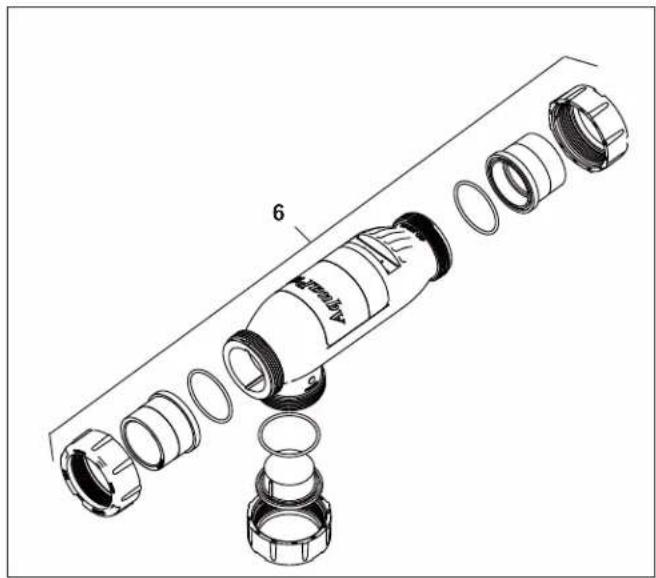
natural_image
Exploded view diagram of a mechanical component with no visible text or symbolsFigure 22. 3-Port Spool Exploded View
9.3 3-Port Electrolytic Cell and Sensor Replacement Parts (2" PVC Unions)
Dwg. # Kit # Description Qty.
| 1 R0475300 | 3-Port Cell, APURE700, 2" Threaded PVC Unions | |
| R0475400 | 3-Port Cell, APURE1400, 2" Threaded PVC Unions includes: | |
| Cell Assembly | 1 | |
| O-Ring, 2" Union, #2-144 | 2 | |
| O-Ring, Plug/Sensor, #2-231 | 1 | |
| DC 16' Power Cord, Black | 1 | |
| Plug, Port CG Cell | 1 | |
| Nut, Union Universal | 1 |
2 R0402800 16' Cable, DC 1
3 R0476300 25' Cable, DC 1
4 R0452500 Port Sensor 16' w/O-Ring, 3-Port Cell
5 R0476400 Port Sensor 25' w/O-Ring, 3-Port Cell
6 R0412500 Nut, 2" PVC Union 1
7 R0412600 Tailpiece, 2" PVC 1
8 R0412700 O-ring, 2" Union 1
9 R0403800 Flow Sensor w/ 16' Cable 1 (Tee Sensor Location Only)
| 10 SP3PLX 3-Port Spool Cleaning Kit includes: | |
| Spool, GC Cell, 3-Port | 1 |
| O-Ring, 2" Union, #2-144 | 3 |
| O-Ring, Plug/Sensor, #2-231 | 2 |
| Nut, 2" PVC Union | 2 |
| Nut, Union Universal | 1 |
| Tailpiece, 2" PVC | 2 |
| Plug, Port CG Cell | 1 |
text_image
1, 2, 3 1, 8 1, 4, 5 4, 5 6 7 9 1 (Plug) 1, 8 6 7 1 1 (Plug)Figure 23. 3-Port Electrolytic Cell and Sensor Exploded View (2" PVC Unions)
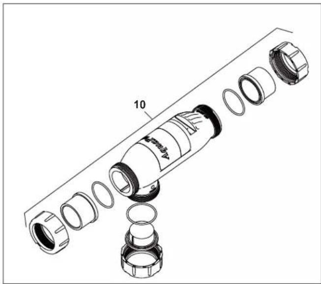
natural_image
Exploded view diagram of a mechanical assembly showing internal components and parts (no text or labels)Figure 24. 3-Port Spool Exploded View
NOTES
NOTES
Zodiac Pool Systems LLC
2882 Whiptail Loop, # 100 Carlsbad, CA 92010
Zodiac Pool Systems Canada, Inc.
2-3365 Mainway, Burlington, ON L7M 1A6 Canada
USA | Jandy.com | 1.800.822.7933
Canada | Jandy.ca | 1.888.647.4004

NSF/ANSI Standard 50

Intertek
ETL LISTED
CONFORMS TO UL STD 1991
CERTIFIED TO
CAN/CSA C22.2 NO. 218.1