
VICM48 - Cooking appliance Vulcan - Free user manual and instructions
Find the device manual for free VICM48 Vulcan in PDF.


| Product type | Cheese melter |
| Brand | Vulcan |
| Model | VICM48 |
| Number of burners | 2 |
| Total nominal power | 40,000 BTU/h (2 × 20,000) |
| Gas type | Natural gas or propane (depending on version) |
| Gas pressure (natural) | Supply pressure min. 7-9 in WC; regulator set at 5 in WC |
| Gas pressure (propane) | Supply pressure min. 11-12 in WC; regulator set at 10 in WC |
| Ignition | Manual pilot flame with red safety button |
| Safety | Pilot flame safety valve, thermocouple |
| Grate | Removable, 4 adjustable positions |
| Crumb tray | Removable, empty when three-quarters full |
| Exterior material | Stainless steel |
| Exterior cleaning | Mild soapy water, avoid abrasive cleaners |
| Interior cleaning | Soak grate and crumb tray in hot water with mild detergent, scrub |
| Lubrication | High-temperature grease by qualified technician |
| Installation | Countertop or wall mount (wall bracket included); clearances: base 10 in (combustible)/4 in (non-combustible), sides 20 in/0 in, rear 2 in/0 in, front 36 in |
| Rating plate location | Under crumb tray on the right side |
| Parts and service | Contact authorized Vulcan service; website: www.vulcanequipment.com |
Frequently Asked Questions - VICM48 Vulcan
User questions about VICM48 Vulcan
0 question about this device. Answer the ones you know or ask your own.
Ask a new question about this device
Download the instructions for your Cooking appliance in PDF format for free! Find your manual VICM48 - Vulcan and take your electronic device back in hand. On this page are published all the documents necessary for the use of your device. VICM48 by Vulcan.
USER MANUAL VICM48 Vulcan
natural_image
Exterior view of a stainless steel VULCAN portable stove with grating and side vent slots (no text or symbols visible)VICM36
MODELS
VICM24
VICM36
VICM48
VICM60
VICM72
WICM24
WICM36
WICM48
WICM60
WICM72
For additional information on Vulcan or to locate an authorized parts and service provider in your area, visit our website at www.vulcanequipment.com
IMPORTANT FOR YOUR SAFETY
THIS MANUAL HAS BEEN PREPARED FOR PERSONNEL QUALIFIED TO INSTALL GAS EQUIPMENT, WHO SHOULD PERFORM THE INITIAL FIELD START-UP AND ADJUSTMENTS OF THE EQUIPMENT COVERED BY THIS MANUAL.
POST IN A PROMINENT LOCATION THE INSTRUCTIONS TO BE FOLLOWED IN THE EVENT THE SMELL OF GAS IS DETECTED. THIS INFORMATION CAN BE OBTAINED FROM THE LOCAL GAS SUPPLIER.
IMPORTANT
IN THE EVENT A GAS ODOR IS DETECTED, SHUT DOWN UNITS AT MAIN SHUTOFF VALVE AND CONTACT THE LOCAL GAS COMPANY OR GAS SUPPLIER FOR SERVICE.
FOR YOUR SAFETY
DO NOT STORE OR USE GASOLINE OR OTHER FLAMMABLE VAPORS OR LIQUIDS IN THE VICINITY OF THIS OR ANY OTHER APPLIANCE.
WARNING
Improper installation, adjustment, alteration, service or maintenance can cause property damage, injury, or death. Read the installation, operating and maintenance instructions thoroughly before installing or servicing this equipment.
IN THE EVENT OF A POWER FAILURE, DO NOT ATTEMPT TO OPERATE THIS DEVICE.
INSTALLATION, OPERATION AND CARE OF CHEESEMELTERS
GENERAL
Cheesemelters are produced with quality workmanship and material. Proper installation, usage and maintenance of your Cheesemelter will result in years of satisfactory performance.
| Model | # of Burners | BTU/hr Input Rating |
| VICM24-L / WICM24-L | 1 | 18,000 |
| VICM36-L / WICM36-L | 1 | 24,000 |
| VICM48-L / WICM48-L | 2 | 36,000 (2 @ 18,000) |
| VICM60-L / WICM60-L | 2 | 42,000 (1 @ 18,000 + 1 @ 24,000) |
| VICM72-L / WICM72-L | 2 | 48,000 (2 @ 24,000) |
| VICM24 / WICM24 | 1 | 20,000 |
| VICM36 / WICM36 | 1 | 30,000 |
| VICM48 / WICM48 | 2 | 40,000 (2 @ 20,000) |
| VICM60 / WICM60 | 2 | 50,000 (1 @ 20,000 + 1 @ 30,000) |
| VICM72 / WICM72 | 2 | 60,000 (2 @ 30,000) |
INSTALLATION
Before installing, verify that the type of gas (natural or propane) and the clearance dimensions (see page 4) agree with the specifications on the rating plate. If the supply and equipment requirements do not agree, do not proceed with the installation. Contact your dealer immediately. It is recommended that a trained gas service technician with the necessary tools, instruments and skills perform the installation of the cheesemelter.
UNPACKING
This cheesemelter was inspected before leaving the factory. The carrier assumes full responsibility for the safe delivery upon acceptance of the shipment. Check for possible shipping damage immediately after receipt.
If the cheesemelter is found to be damaged, complete the following steps:
- Carrier must be notified within 5 business days of receipt.
- Carrier's local terminal must be notified immediately upon discovery (note time, date, and who was spoken to), and follow up and confirm with written or electronic communication.
- All original packing materials must be kept for inspection purposes.
- The cheesemelter cannot have been moved, installed, or modified.
- Notify Vulcan Customer Service immediately at 800-814-2028.
Before using, remove all packaging material and protective plastic from the surfaces of the unit. Carefully unpack your cheesemelter and make sure that no parts are discarded with the packaging material. A pressure regulator designed to operate with the cheesemelter has been supplied and must be installed before the cheesemelter is placed into service. (Refer to GAS PRESSURE REGULATOR INSTALLATION in this manual).
LOCATION
The equipment area must be kept free and clear of combustible substances.
Minimum Clearances
Combustible Construction Non-Combustible Construction
| Back | 2" | 0" |
| Sides | 20" | 0 |
| Bottom | 10" | 4" |
The installation location must allow adequate clearances for servicing and proper operation. While another gas-fired cheesemelter can be placed adjacent to this Cheesemelter, there must be no obstruction to the front of the Cheesemelter. A minimum front clearance of 36" (91 cm) is required.
It is recommended that the cheesemelter not be installed directly over or directly adjacent to charbroilers, griddles or fryer banks. Infrared burners can be susceptible to the effects of grease laden smoke and installation in these locations may shorten burner life. The cheesemelter must be installed so that it is level side to side and front to back.
Do not obstruct the flow of combustion and ventilation air. Adequate clearance for air openings into the combustion chamber must be provided. Make sure there is an adequate supply of air in the room to replace air taken out by the ventilating system.
Do not permit fans to blow directly at the Cheesemelter. Avoid wall-type fans which create air cross currents within the room. Avoid open windows next to the Cheesemelter. Maintain a minimum 18" (46 cm) clearance from the top of the cheesemelter flue vent to the filters of the hood venting system or any other obstruction. Maintain a minimum 18" (46 cm) clearance from the bottom of the cheesemelter to any other flue discharge area.
INSTALLATION CODES AND STANDARDS
The Cheesemelter must be installed in accordance with:
In the United States of America:
- State and local codes.
- National Fuel Gas Code, ANSI-Z223.1/NFPA #54 (latest edition). This shall include but not be limited to: NFPA #54 Section 10.3.5.2 for Venting. Copies may be obtained from The American Gas Association Accredited Standards Committee Z223, @ 400 N. Capital St. NW, Washington, DC 20001 or the Secretary Standards Council, NFPA, 1 Batterymarch Park Quincy, MA 02169-7471
NOTE: In the Commonwealth of Massachusetts
All gas appliances vented through a ventilation hood or exhaust system equipped with a damper or with a power means of exhaust shall comply with 248 CMR.
- NFPA Standard # 96 Vapor Removal from Cooking Equipment, latest edition, available from the National Fire Protection Association, Batterymarch Park, Quincy, MA 02269.
In Canada:
- Local codes.
- CAN/CSA-B149.1 Natural Gas Installation (latest edition)
- CAN/CSA-B149.2 Propane Installation Code (latest edition), available from the Canadian Gas Association, 178 Rexdale Blvd., Etobicoke, Ontario, Canada M9W 1R3
WARNING The cheesemelter and its parts are hot. Use care when operating, cleaning or servicing the cheesemelter.
ASSEMBLY
Counter Mounting
- Cheesemelters mounted on a counter must be equipped with 4" (10 cm) legs (sold separately).
- Remove the leg knockouts on the bottom of the unit to expose the threaded attachment points. 60 and 72 models will require 6 legs.
- Screw the legs into the threaded attachment points on the bottom of the unit.
- Place Cheesemelter in position, then level by adjusting the bullet feet.
WARNING Ensure the counter is of noncombustible construction.
Wall Mounting
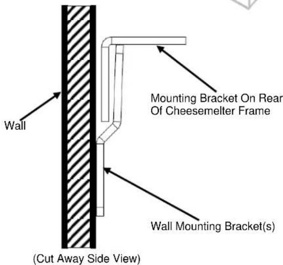
- Make sure the wall bracket(s) are level and properly spaced on the wall so that they will align with the mounting bracket on the rear of the cheesemelter frame.
- Attach the wall mount bracket(s) to the wall with suitable fasteners (not supplied) to match the onsite construction. 48, 60 and 72 models will will have two wall mount brackets.
- Hang the cheesemelter from its built-in mounting bracket onto the wall mounting brackets.
⚠ WARNING Ensure the mounting wall is of noncombustible construction and will support the weight of the cheesemelter.
| Model | Weight |
| VICM24 / WICM24 | 130 lbs/59 kg |
| VICM36 / WICM36 | 160 lbs/73 kg |
| VICM48 / WICM48 | 200 lbs/91 kg |
| VICM60 / WICM60 | 225 lbs/102 kg |
| VICM72 / WICM72 | 260 lbs/118 kg |

natural_image
Technical line drawing of a mechanical device with internal components and scroll wheel (no text or symbols)
Special Hi-Shelf Mounting
If the Cheesemelter is to be mounted over a Gas Range, a reinforced hi-shelf designed to support the weight of the cheesemelter is required.
- Remove the knockouts on the bottom of the unit to expose the threaded attachment points.
- Place and align Cheesemelter on top of shelf brackets; place the back of the unit flush with the rear of the shelf.
- Align holes in the shelf(may be necessary to drill holes) with the threaded attachment points on the bottom of the cheesemelter.
- Secure cheesemelter into place with four 3/8"-16 bolts(not included). Thread the bolts through the shelf and into the threaded attachment points on the bottom of the cheesemelter.

natural_image
Technical line drawing of a multi-level appliance or storage unit with mounting feet and ventilation grilles (no text or symbols)GAS CONNECTIONS
⚠ WARNING Gas supply connections and any pipe joint compound must be resistant to the action of propane gases.
Location of the gas inlet is at the top right rear corner of the top panel. Codes require that a gas shutoff valve must be installed in the gas line ahead of the Cheesemelter.
Use a 34 " NPT gas supply line for the cheesemelter inlet. All flexible and semi-rigid gas supply lines must comply with the applicable ANSI standard. To ensure maximum operating efficiency this appliance must be connected with a gas supply line of solid pipe or a commercial type Flexible Connector with the net inside diameter (I.D.) as large as or larger than the gas pipe inlet on this appliance.
WARNING Prior to lighting, check all joints in the gas supply line for leaks. Use soap and water solution. Do not use an open flame.
After checking for leaks all lines receiving gas should be fully purged to remove air.
Maximum line pressure for natural and propane gas is 14" W.C. Minimum line pressure is 7" W.C. for natural gas and 11" W.C. for propane gas.
TESTING THE GAS SUPPLY SYSTEM
When gas supply pressure exceeds 12 psig (3.45 kPa), the Cheesemelter and its individual shutoff valve must be disconnected from the gas supply piping system. When gas supply pressure is 12 psig (3.45 kPa) or less, the Cheesemelter should be isolated from the gas supply system by closing its individual manual shutoff valve.
FLUE CONNECTIONS
Do not obstruct flow of flue gases from the flue located on the rear of the Cheesemelter. It is recommended that the flue gases be ventilated to the outside of the building through a ventilation system installed by qualified personnel. Information on the construction and installation of ventilating hoods may be obtained from the standard for "Vapor Removal from Cooking Equipment," NFPA No. 96 (latest edition), available from The National Fire Protection Association, Batterymarch Park, Quincy, MA 02269.
GAS PRESSURE REGULATOR INSTALLATION
Gas regulator pressure is preset at 5" Water Column (W.C.) for natural gas, and 10" W.C. for propane gas. Minor adjustments may be required based on site specific gas pressure.
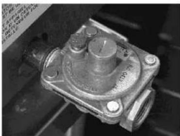
Install the regulator as close to the cheesemelter on the gas supply line as possible. Make sure that the arrow on the underside of the regulator is oriented in the direction of gas flow to the cheesemelter (Fig. 2) and the regulator is positioned with the vent plug and adjustment screw upright (Fig. 3).

natural_image
Close-up of a mechanical component with no visible text or symbolsFig. 2
natural_image
Close-up of a metallic mechanical valve component with threaded ports and mounting holes (no visible text or symbols)Fig. 3
The minimum supply pressure (upstream of the regulator) should be 7-9" W.C. for natural gas and 11-12" W.C. for propane gas. At no time should the cheesemelter be connected to supply pressure greater than 12 psig (3.45 kPa) or 14" W.C.
⚠ WARNING Gas supply connections and any pipe joint compound must be resistant to the action of propane gases.
WARNING Prior to lighting, check all joints in the gas supply line for leaks. Use soap and water solution. Do not use an open flame.
OPERATION
WARNING The cheesemelter and its parts are hot. Use care when operating, cleaning or servicing the cheesemelter.
LOADING AND UNLOADING
Place the rack in the desired position. Pull the rack out for loading and avoid spillage. Push the rack into place and cook for the appropriate time. Pull the rack out for unloading.
PREHEATING
After lighting the pilot, turn the burner valve knob completely counterclockwise (to the MAX position) and preheat for 15 minutes.
RECIPE AND RACK ADJUSTMENT
Positioning the Cheesemelter rack is an important factor in the desired product end results. Position the rack farther away from the burners for thick casseroles and for melting cheese or butter to avoid drying the product. Position the rack closer to the burners for bacon, toast and quick heating, but watch carefully to avoid burning.
CLEANING
WARNING The cheesemelter and its parts are hot. Use care when operating, cleaning or servicing the cheesemelter.
Interior
When the Cheesemelter is cool, remove rack. Clean the rack and crumb tray daily by soaking in warm detergent water. Scrub with a stiff-bristled brush. Do not use harsh abrasives.
After scrubbing, wash with soapy water, rinse and dry. Rinse with wet towel, do not spray unit with a water jet. Soap and water will normally do the job. Heavy spattering or spillovers may require cleaning with mild cleaner or soapy wet pads.
Exterior
When the Cheesemelter is cool, knobs and stainless steel surfaces may be cleaned with mild soap and water applied with a damp cloth. Wipe the surface with clean water and dry with a soft clean cloth. Do not use abrasive cleaners or strong liquid cleaners on stainless steel surfaces as they may damage the finish.
Spray-On Cleaners
Be careful when using spray-on cleaners. Some cleaners may contain caustics. Please follow cleaner manufacturer's instructions.
CONTROLS
WARNING The cheesemelter and its parts are hot. Use care when operating, cleaning or servicing the cheesemelter.

Red Pilot Safety Button (Safety Equipped Units Only)
This will only be on specially designated units with a pilot safety system. The button will be depressed during the pilot lighting procedure. See page 10.
Burner Valve
Each burner is independently controlled by an infinite control burner valve. Once the pilots are lit, turning the burner valves to the MAX position (completely counter clockwise) will light each burner. The burner valves regulate the flow of gas to the burners. Gas flow is increased by turning the valve counterclockwise.
Pilot Adjustment Valve
The pilot adjustment valve regulates the flow of gas to the pilot burner. Using a flathead screwdriver, turn the slotted screw clockwise to decrease the flame, and counter clockwise to increase the flame.
Rack
There are three rack positions. Place the shelf on the rack needed for Cheesemelting. For deeper, longer heat, use lower positions. For thinner foods, or faster cooking, use top shelves.
Crumb Tray
The crumb tray collects crumbs and waste. Do not allow the crumb tray to overflow. Empty the crumb tray when three-quarters full to reduce the possibility of spillage.
SHUTDOWN
- Turn the burner valve knobs completely clockwise (to OFF position) to cut off burners.
- The pilots will remain lit as long as the gas supply is on.
EXTENDED SHUTDOWN
- Turn the burner valve knobs completely clockwise (to OFF position) to cut off burners.
- Turn the unit gas shutoff valve to the OFF position.
LIGHTING THE PILOT
- Turn all controls to the "OFF" position, wait 5 minutes.
- Light pilot. If applicable: (Depress red button on safety valve and light pilot. Hold red button down for at least 30 seconds. When button is released, pilot should remain lit.)
- Pilot flame may be adjusted with screw on pilot valve. There should be only a slight amount of yellow in properly adjusted pilot flame.
- Adjust burner controls as necessary.
- For complete shutdown, turn all control valves to "OFF".

MAINTENANCE
WARNING
The cheesemelter and its parts are hot. Use care when operating, cleaning or servicing the cheesemelter.
LUBRICATION
All moving parts must be checked for wear and lubricated if necessary. Contact your local Service Contractor.
All valves and controls should be lubricated with a high-temperature grease by a trained service technician.
FLUE
When the Cheesemelter is cool, check the flue and clear any obstructions. Never block flue or place anything on top of the cheesemelter.
SERVICE AND PARTS INFORMATION
Contact your local Service Contractor for any repairs or adjustments needed on this equipment. For a complete listing of service and parts depots refer to www.vulcanequipment.com. When calling for service, the following information should be available from the appliance identification plate: Model Number and Serial Number. The identification plate is located under the crumb tray on the right side.
TROUBLESHOOTING
natural_image
Close-up of a mechanical component with no visible text or symbolsFig.2

natural_image
Close-up of a mechanical component with metallic parts and bolt holes (no visible text or symbols)natural_image
Technical line drawing of a cabinet or rack structure with mounting holes and internal compartments (no text or symbols)BRANCHEMENTS DU GAZ
| Modele | Poids |
| VICM24 / WICM24 | 130 lbs/59 kg |
| VICM36 / WICM36 | 160 lbs/73 kg |
| VICM48 / WICM48 | 200 lbs/91 kg |
| VICM60 / WICM60 | 225 lbs/102 kg |
| VICM72 / WICM72 | 260 lbs/118 kg |
natural_image
Technical line drawing of a mechanical enclosure or enclosure with internal compartments and mounting points (no text or symbols)natural_image
Exterior view of a stainless steel electric stove appliance (no visible text or symbols)FOUR A GRATIENER
MANUEL D'INSTALLATION ET D'UTILISATION
WOLF

UBATNA
- MODELS
- IMPORTANT FOR YOUR SAFETY
- IMPORTANT
- FOR YOUR SAFETY
- WARNING
- INSTALLATION, OPERATION AND CARE OF CHEESEMELTERS
- GENERAL
- INSTALLATION
- UNPACKING
- LOCATION
- INSTALLATION CODES AND STANDARDS
- The Cheesemelter must be installed in accordance with:
- NOTE: In the Commonwealth of Massachusetts
- ASSEMBLY
- Counter Mounting
- Wall Mounting
- Special Hi-Shelf Mounting
- GAS CONNECTIONS
- TESTING THE GAS SUPPLY SYSTEM
- FLUE CONNECTIONS
- GAS PRESSURE REGULATOR INSTALLATION
- OPERATION
- LOADING AND UNLOADING
- PREHEATING
- RECIPE AND RACK ADJUSTMENT
- CLEANING
- Interior
- Exterior
- Spray-On Cleaners
- CONTROLS
- Red Pilot Safety Button (Safety Equipped Units Only)
- Burner Valve
- Pilot Adjustment Valve
- Rack
- Crumb Tray
- SHUTDOWN
- EXTENDED SHUTDOWN
- LIGHTING THE PILOT
- MAINTENANCE
- LUBRICATION
- FLUE
- SERVICE AND PARTS INFORMATION
- BRANCHEMENTS DU GAZ
- FOUR A GRATIENER
- MANUEL D'INSTALLATION ET D'UTILISATION
Brand : Vulcan
Model : VICM48
Category : Cooking appliance