
FCS-8000-VFD - Smoke detector BOSCH - Free user manual and instructions
Find the device manual for free FCS-8000-VFD BOSCH in PDF.

| Product Type | Video-based fire detection camera (smoke and flame detector) |
| Model | FCS-8000-VFD (AVIOTEC IP starlight 8000) |
| Dimensions (W x H x L) | 78 x 66 x 140 mm (without lens) |
| Weight | 855 g (without lens) |
| Power Supply | PoE (IEEE 802.3af) or 12 VDC auxiliary (SELV-LPS/Class 2) |
| Operating Temperature | -20°C to +50°C |
| Storage Temperature | -30°C to +70°C |
| Operating Humidity | 20% to 93% RH |
| Minimum Illumination | 2 lx (0 lx with IR illumination) |
| Detection Types | Smoke (smoldering fires) and flame |
| Minimum Smoke Size | 1.6% of picture width (default) |
| Minimum Flame Size | 1.1% of picture width (default) |
| Smoke Verification Time | 10 to 30 seconds (adjustable) |
| Flame Verification Time | 4, 8, 12, or 16 seconds (adjustable) |
| Alarm Output | 1 relay, max 30 VAC or +40 VDC, 0.5 A continuous |
| Alarm Input | 2 inputs (TTL, +5 V nominal) |
| Ethernet Interface | RJ45, 10/100 Base-T, auto-MDIX |
| Memory Card Slot | microSDHC up to 32 GB / microSDXC up to 2 TB |
| Lens Mount | Supplied or approved lenses only (motorized back focus) |
| Mounting Options | Ceiling, wall, or stand mount |
| Maintenance | Clean lens with dry cloth; no user-serviceable parts |
| Safety | Install by qualified personnel; avoid obstructions and backlight; minimum 2 lx |
| Spare Parts / Repairability | Only approved lenses; refer repairs to qualified specialists |
| Network Protocols | IPv4, IPv6, UDP, TCP, HTTP, HTTPS, RTSP, FTP, DHCP, etc. |
| Certification | VdS (partial; Expert Mode not VdS certified) |
Frequently Asked Questions - FCS-8000-VFD BOSCH
User questions about FCS-8000-VFD BOSCH
0 question about this device. Answer the ones you know or ask your own.
Ask a new question about this device
Download the instructions for your Smoke detector in PDF format for free! Find your manual FCS-8000-VFD - BOSCH and take your electronic device back in hand. On this page are published all the documents necessary for the use of your device. FCS-8000-VFD by BOSCH.
USER MANUAL FCS-8000-VFD BOSCH
AVIOTEC IP starlight 8000
FCS-8000-VFD-B / Firmware 7.8x
en
Operation Manual
Table of contents
| 1 | Safety instructions 5 | |
| 1.1 General Safety Messages / Notices 5 | ||
| 2 | Introduction 8 | |
| 2.1 Disclaimer 8 | ||
| 2.2 About this manual 8 | ||
| 2.3 Conventions in this manual 8 | ||
| 2.4 Definition of optical terms 8 | ||
| 2.4.1 Illumination 9 | ||
| 2.4.2 Focal length 9 | ||
| 2.4.3 Monitoring Area 10 | ||
| 2.4.4 Different angle types 10 | ||
| 3 | System Overview 13 | |
| 3.1 Algorithm | 13 | |
| 3.1.1 Flame detection characteristics | 13 | |
| 3.1.2 Smoke detection characteristics | 13 | |
| 4 | Installation 18 | |
| 4.1 Requirements | 18 | |
| 4.2 Preparation in the office | 19 | |
| 4.3 On-site commissioning | 19 | |
| 4.4 Lens mounting | 19 | |
| 4.5 Camera mounting | 20 | |
| 4.6 Setting the field of view | 21 | |
| 4.7 Wiring of the camera 22 | ||
| 4.8 Alarm output | 23 | |
| 4.9 Alarm input 24 | ||
| 5 | Camera integration | 27 |
| 5.1 Local Area Network | 28 | |
| 5.2 Local Area Network with recording solution | 28 | |
| 5.3 Monitoring Center 29 | ||
| 5.4 Fire Alarm Control Panel | 29 | |
| 5.5 Mobile Devices | 30 | |
| 6 | Access to the device | 32 |
| 6.1 Access via web interface | 32 | |
| 6.2 Configuration Manager | 32 | |
| 7 | Adjustment of detection settings | 33 |
| 7.1 General settings | 33 | |
| 7.2 Adjustments of image regions | 34 | |
| 7.3 Adaptation to the lighting situation | 37 | |
| 7.3.1 General lightning settings | 37 | |
| 7.3.2 Flickering | 37 | |
| 7.4 Expert Mode (not VdS certified) | 38 | |
| 7.4.1 Color | 38 | |
| 7.4.2 ALC | 39 | |
| 7.4.3 Enhance | 40 | |
| 7.5 Relay settings | 40 | |
| 8 | Use cases | 42 |
| 8.1 Fire detection only | 42 | |
| 8.2 Fire detection and VCA profiles | 42 | |
4 en | Table of contents AVIOTEC IP starlight 8000
8.3 Scheduled fire detection 42
8.4 External trigger to switch fire detection mode 43
9 Troubleshooting 45
9.1 False Alarms 45
9.1.1 Quick solution to solve false alarms 45
9.1.2 False alarms under 4 seconds concerning the whole detection area 45
9.1.3 False alarms at small constant areas 45
9.1.4 Vibrations at the camera site 46
9.2 No alarm transmission 46
9.3 No fire detection 46
9.4 Image quality 46
9.5 Camera 46
10 Maintenance 48
10.1 Cleaning 48
10.2 Repair 48
10.3 Reset 48
10.4 Maintenance intervals 48
11 Technical data 50
1 Safety instructions
In this document, the following symbols and notations are used to draw attention to special situations:
Danger!
Indicates a hazardous situation which, if not avoided, will result in death or serious injury.

Warning!
Indicates a hazardous situation which, if not avoided, could result in death or serious injury.

Caution!
Indicates a hazardous situation which, if not avoided, could result in minor or moderate injury.

Notice!
Indicates a situation which, if not avoided, could result in damage to the equipment or environment, or data loss.
1.1 General Safety Messages / Notices

Warning!
Do not moisten the electronic appliances inside of the lens.
It may cause fire or electric shock. In this case, shut off the power supplied to the lens immediately.

Caution!
The Low Voltage power supply unit must comply with EN/UL 60950. The power supply must be a SELV-LPS unit or a SELV - Class 2 unit (Safety Extra Low Voltage - Limited Power Source).

Caution!
Installation should only be performed by qualified service personnel in accordance with the National Electrical Code (NEC 800 CEC Section 60) or applicable local codes.

Caution!
Do not leave or store the lens under direct sunshine.
The lens may focus rays of light on a near-by object and cause fire.

Caution!
In case of unusual behavior, smoke, noise or smell coming out of the lens, shut off the power immediately and pull out the lens cable.
Notify the installer or sales agent from which you purchased the product.
6 en | Safety instructions AVIOTEC IP starlight 8000
| Caution!Make sure to test the fire detection after updating to the latest firmware. | |
| Notice!Avoid obstructions in the field of view!Covered fires cannot be detected correctly. An unobstructed view of the detection area is necessary. | |
| Notice!Activating video-based fire detection sets camera settings to a specific preset.This preset affects several camera settings as long as this mode is activated. | |
| Notice!No detection of moving fire.Moving fires will not be detected by the video-based fire detection. | |
| Notice!No direct connection to fire services in EN54 compliant installations.Authorities can allow a connection to fire services after verifying alarms in a monitoring center. | |
| Notice!Minimum Illumination required.To ensure the proper functioning of the video-based fire detection algorithm, a minimal illumination of 2 lx is required. If the illumination is less than 2 lx, an additional IR illumination is required. | |
| Notice!Calm wind conditions only.Strong air currents can cause false alarms by raising dust or debris similar in appearance to fire and smoke. | |
| Notice!Respect data protection.The relevant data protection and privacy rules are to be complied with. | |
| Notice!Avoid backlight.Backlight can disturb the video-based fire detection algorithm. | |
| Notice!Optimized smoke detection.The video-based fire detection algorithm is optimized for smoke of smoldering fires. |
AVIOTEC IP starlight 8000 Safety instructions | en 7
 | Notice! Qualified personnel only. Assembly and installation must only be performed by qualified personnel. |
 | Notice! Reduced detection distances at image margin area. Due to optical distorsion of the lens, the maximum detection distances at the image margin area are reduced. |
 | Notice! Avoid image regions with continuous upward motion. Continuous upward motion might lead to false alarms. |
 | Notice! Make sure the camera is firmly mounted. Camera shake might lead to false alarms. Avoid vibrations of the camera and the camera environment. |
 | Notice! No detection of irregular expanding smoke. Smoke plumes must move in a constant direction with a minimum density to be detected by the video-based fire detection. |
 | Notice! Ensure that you are always using the latest version of the operation manual and the current camera firmware. The manufacturer will not be held liable for any damages resulting from the use of older versions. |
 | Notice! No detection in blinking light regions in the detection area. |
 | Notice! Only use the supplied lens or approved lenses. Do not use other lenses. A reliable functioning of the product cannot be guaranteed with other lenses. |
 | Notice! Bright areas in the background (e.g., white areas, sun or sky) limit the detection of flames or can lead to flames not being detected. |
 | Notice! Flame-colored background in the picture is to be avoided, since a reliable detection cannot be ensured! |
2 Introduction
2.1 Disclaimer
IMPORTANT: Video fire indication systems are video content analysis systems. They give indications for possible fires and are designed to supplement fire detection systems and human guards in monitoring centers in order to recognize possible dangerous situations. Video fire indication systems are confronted with a higher amount of challenges considering scenery and background compared to conventional fire detection systems. They cannot ensure that fire will be detected reliably in all scenery settings. Thus, the video fire detection system shall be seen as a support system that enhances the probability of early fire detection, with the restriction that it shall not be seen as a system that ensures fire detection in all possible image scenarios and it might detect false alarms. Conventional fire alarm systems must in no way be replaced by video-based fire alarm systems.
In addition, and for the U.S. market only, Bosch Security Systems makes no representation that the video fire indication system will prevent any personal injury or property loss by fire or otherwise; or that such product will in all cases provide adequate warning or protection. Buyer understands that a properly installed and maintained fire indication system may only reduce the risk of a fire or other events occurring without providing an alarm, but it is not insurance or a guarantee that such will not occur or that there will be no personal injury or property loss as a result.
Consequently, Bosch Security Systems shall have no liability for any personal injury, property damage or other loss based on a claim the product failed to give warning.
2.2 About this manual
This manual has been compiled with great care and the information it contains has been thoroughly verified. The text was correct at the time of printing, however, the content can change without notice. Bosch Security Systems accepts no liability for damage resulting directly or indirectly from faults, incompleteness or discrepancies between this manual and the product described.
For more information please contact the nearest Bosch Security Systems location or visit www.boschsecurity.com.
All hardware and software product names used in this document are likely to be registered trademarks and must be treated accordingly.
The operation manual provides an overview of possibilities and fields of application of the video-based fire detection. It should be a guideline for customer-specific application planning.
2.3 Conventions in this manual
Terms concerning the adjustment of the smoke and flame algorithm, such as menu options, commands or text in the user interface, are written in bold.
2.4 Definition of optical terms
The reflected light coming from the field of view arrives at the camera lens. The image sensor of the camera transforms the light into electric signals. This electrical image is the basis for further data processing. This chapter contains basic descriptions of optical terms.
2.4.1 Illumination

Notice!
Different illumination levels can lead to different detection speeds. The poorer the ambient illumination, the less the smoke stands out against the background. For this reason, poor lighting < 7 lx may require a higher smoke density for reliable smoke detection.
Illumination is an important influencing factor for sensible optical systems. Natural light shows the huge range of illumination values from direct sunlight (\~100.000 lx) to full moon on a clear night (\~1.0 lx). A luxmeter can be used to measure the light levels.
The following table provides an overview of typical illumination values in different application areas:
| Application Area Illumination (in lx) | |
| Storage facility 50 | |
| Process plants 200 | |
| Sales room 300 | |
| Office space 500 |
In general a uniformly illuminated monitoring area is advantageous for the video-based fire detection. Backlight should be avoided.
Dynamic range
The dynamic range is the ratio between the darkest spot compared to the lightest spot in the application. Use a luxmeter to determine the brightness in your application. The dynamic range in the camera image / the detection area must be equal or less than factor 5.
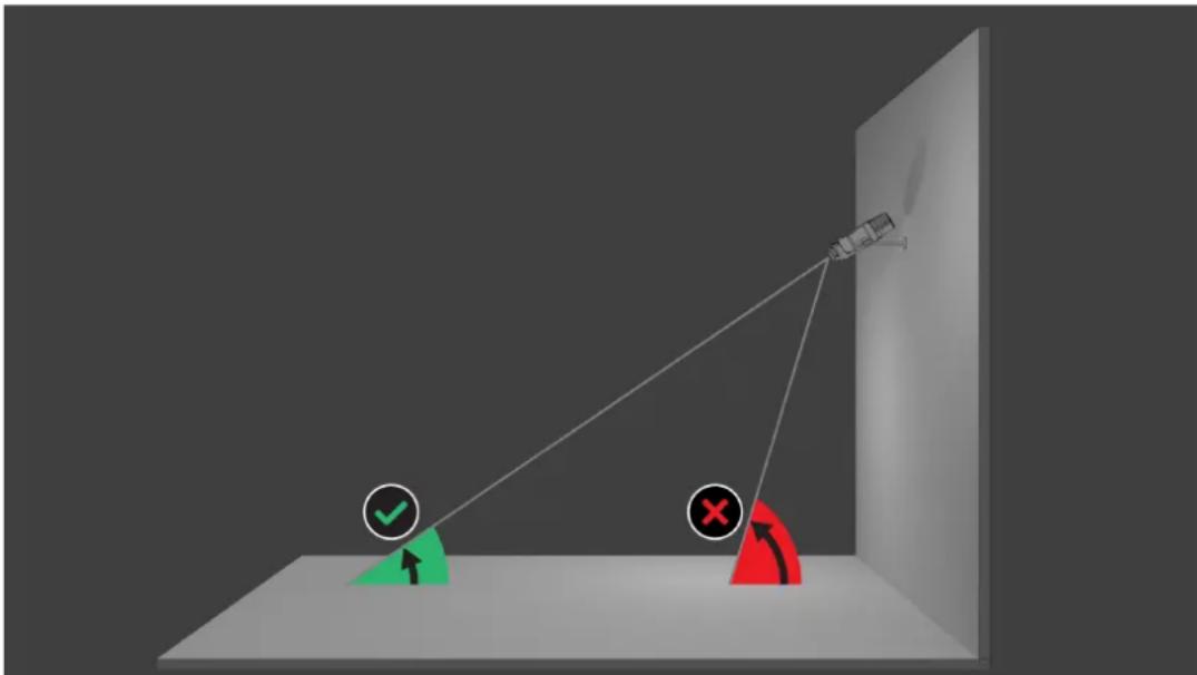
2.4.2 Focal length
The focal length of an optical system defines the distance between a light refracting lens and the focal point. Field of view, maximum distance and field angle are dependant as shown in the graphic below.
bar
| Color | Value | |--------|-------| | Red | 4.1 | | Yellow | 6.5 | | Green | 9 |The maximum width of the field of view may be realized by the minimum focal length. This adversely affects the maximum distance to a detectable fire (red).
The maximum distance to a detectable fire may be reached by adjusting the largest focal length which decreases the width of the field of view to the minimum (green).
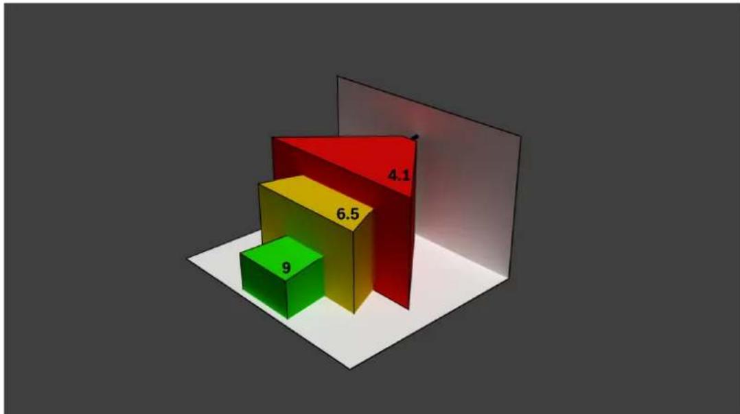
2.4.3 Monitoring Area
natural_image
Diagram showing a camera projecting a curved surface with a flame symbol, no text or labels presentThe monitoring area defines the effective space that can be observed by the video-based fire detection. It is depending on the setting of the camera lens.
2.4.4 Different angle types
There are different types of angles influencing the set-up of the camera. The following overview helps to get a better understanding of angles which are important for the video-based fire detection.
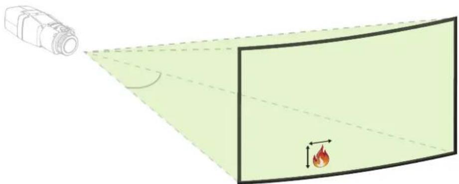
Angle between ground and line of sight
The angle between a fire on the ground and the line of sight to the camera is important for the flame and smoke detection. This angle needs to be 37.5% or less, otherwise flame or smoke will not be detected.
natural_image
Diagram showing a camera setup with green and red directional arrows, no text or symbols presentOpening angle of the lens
The opening angle of the lens can be set from wide-angle to telephoto setting. This influences the field of view of the camera.
natural_image
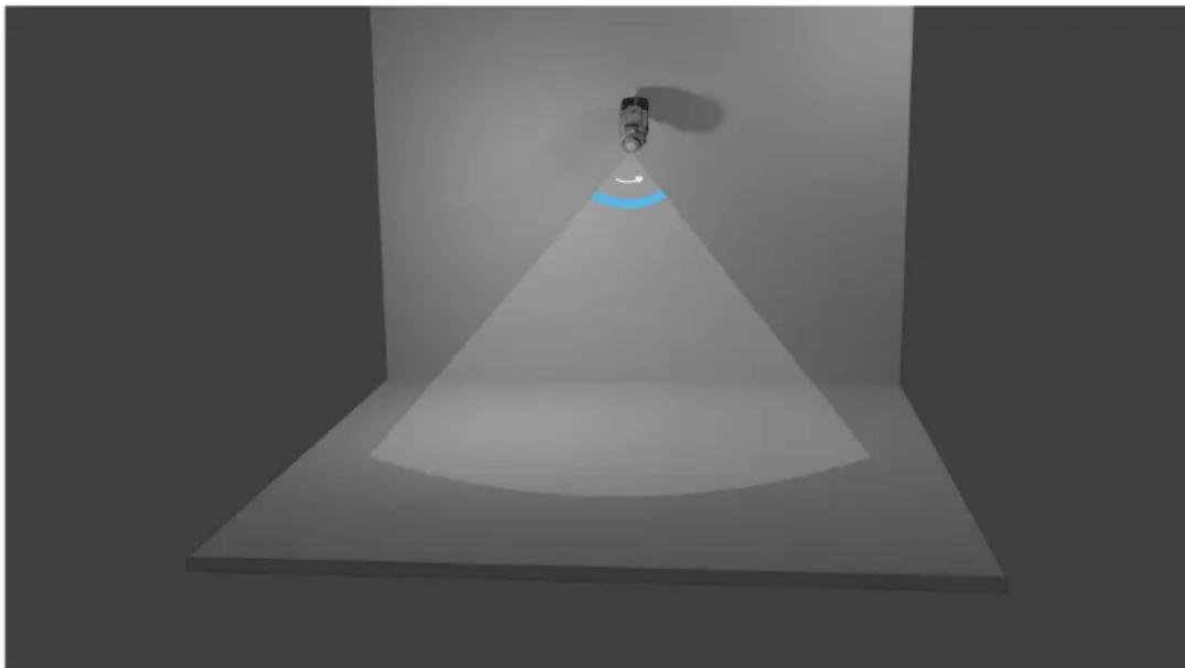
3D rendering of a conical spotlight beam with a small object at the tip, shown in perspective view (no text or symbols)Angle for vertical alignment of the camera
The vertical alignment of the camera is also important for the video-based fire detection. A flat angle is recommended.
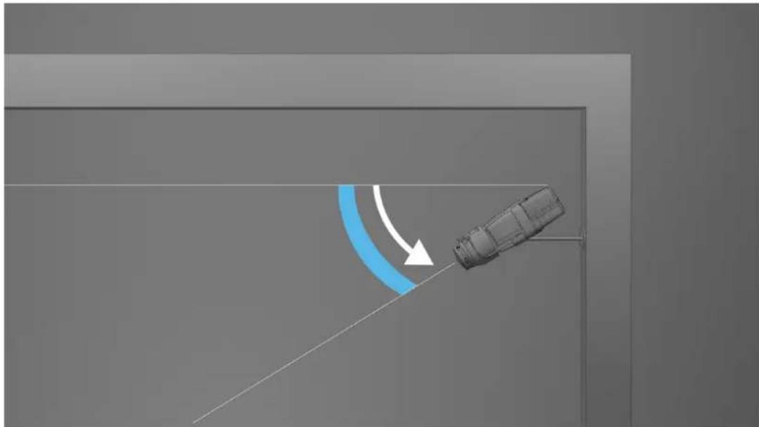
natural_image
3D diagram of a mechanical component with a curved blue arc and white arrow indicating motion direction (no text or symbols)Angle for horizontal alignment of the camera
Align the camera according to your application by adjusting the angle of the horizontal alignment of the camera.
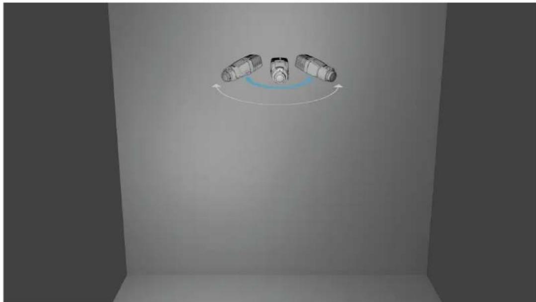
natural_image
Diagram showing three cylindrical objects with curved arrows indicating rotation or motion (no text or symbols)3 System Overview
The video-based fire detection is the system of choice when reliable video motion and fire detection is needed, e.g. applications which are not subjected to construction product regulation or a supplementation to existing fire detection systems. AVIOTEC IP starlight 8000 operates as stand-alone unit and doesn't need a separate evaluation unit. Furthermore, it contains all features of the Intelligent Video Analytics which allows analyzing and evaluating moving objects in parallel. Video-based fire detection and Intelligent Video Analytics operate independently from each other and are separately adjustable.
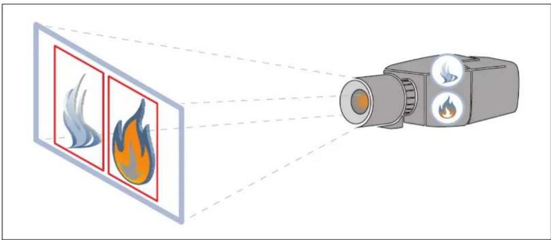
natural_image
Illustration of a camera emitting flame detection from two screens (no text or symbols)3.1 Algorithm
The intelligent smoke and flame algorithm analyzes video frames by means of characteristic and predefined patterns and variables. The fast detection algorithm is based on a real-time image processing on the camera firmware.
There are factors that can influence this kind of visual fire detection. It is important to avoid obstructions in the field of view. Sometimes obstructions cannot be prevented, e.g. building construction factors or huge machine parts. In this case it is necessary to analyze whether there is any need for further video-based fire detection cameras.
3.1.1 Flame detection characteristics
Flames will be analyzed by means of their behavior. Flickering, brightness and constant illuminated parts of white and orange are the basis colors for the algorithm to split off the video image into important and unimportant areas. Further flame colors will not be considered, for example a blue flame might not be detected.
Another algorithm characteristic to identify flames is the flickering of a flame. Objects with a similar movement pattern might cause false alarms, e.g. loose fluttering objects. The video-based fire detection offers subsequent adaption of flame detection settings for this purpose. Air turbulence can have an influence on the visibility of the flame core and flickering. E.g., if the flame is moved back and forth too quickly by wind, this can lead to the flame not being detected in the camera image.
3.1.2 Smoke detection characteristics

Notice!
Different illumination levels can lead to different detection speeds. The poorer the ambient illumination, the less the smoke stands out against the background. For this reason, poor lighting < 7 lx may require a higher smoke density for reliable smoke detection.
The video-based fire detection is optimized for smoke of smoldering fires. The algorithm analyzes smoke based on physical characteristics. Typically a plume of smoke is formed in a regular upward motion of smoke at the same position. This is characterized by a thick column of smoke which is directly visible. Speed and angle of smoke may vary. The maximum detectable speed can be found in the chapter Technical data, page 50. Only color-neutral smoke (white, grey, black) will be detected by the smoke algorithm.
The area in which the smoke density decreases is called ambient smoke. The smoke motion is not directly visible. Ambient smoke will not be detected.
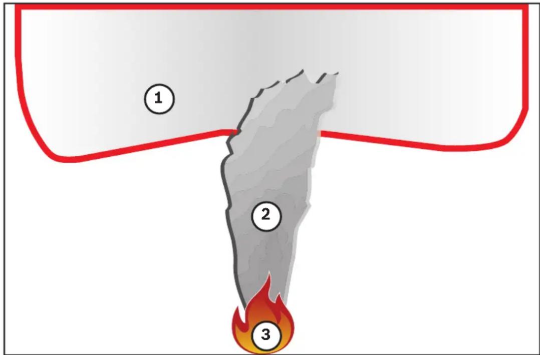
| 1 Ambient smoke | |
| 2 Smoke plume | |
| 3 Fire |
Minimum and maximum smoke width and motion speed
A minimum speed of smoke is needed together with a minimum width of the smoke plume to be detected by the video-based fire detection. The minimum motion speed of smoke and the minimum width have to be reached at the same location in the smoke plume. The same applies to the maximum detection speed and maximum width. It is not sufficient to measure one value at the bottom and the other value at the top of the smoke plume (see chapter Technical data, page 50).
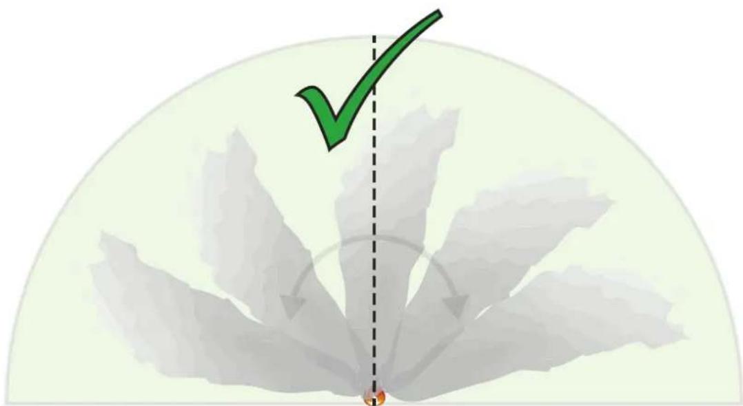
Direction and angle of a smoke plume
The inclination angle and direction of a smoke plume are important indicators to detect smoke. In the field of view of the camera, moving smoke plumes can have a maximum tilt angle of 90^ and will be detected.
natural_image
Illustration of a green checkmark over a fan-shaped background with arrows, no text or symbols presentSmoke plumes must move in a constant direction with a minimum density to be detected by the video-based fire detection. Irregular expanding smoke and smoke plumes moving in the direction of the camera might not be detected.
natural_image
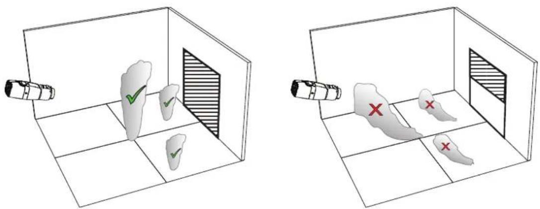
Two 3D diagrams showing a room with tooth samples and a camera, one with checkmarks and another with red X marks (no text or symbols)The intelligent smoke detection covers a large area of application. Nevertheless, there might be some disruptive factors in the operational environment of the customer. Objects with a similar movement pattern of smoke might cause false alarms, e.g. escalators or conveyor belts.
Smoke density
A minimum smoke density is required to identify the smoke plume.
The smoke density is described as the decrease of a local image contrast with the presence of smoke as seen in the following graphic:
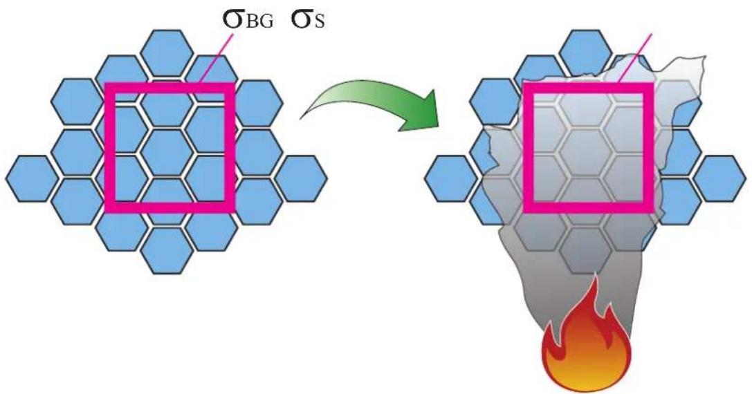
Figure 3.1: Smoke density definition
The effect of contrast reduction by smoke is described by the formula
$$ d = \left(1 - \frac {\sigma_ {S}}{\sigma_ {B G}}\right) * 100 $$
with the contrast values for a temporal average image with smoke _s and the contrast for the background _bg .
Exemplary images for smoke densities are shown in the following table:
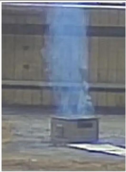
natural_image
Exterior view of a modern office building (no signage)Smoke density: 40% Smoke density: 90%
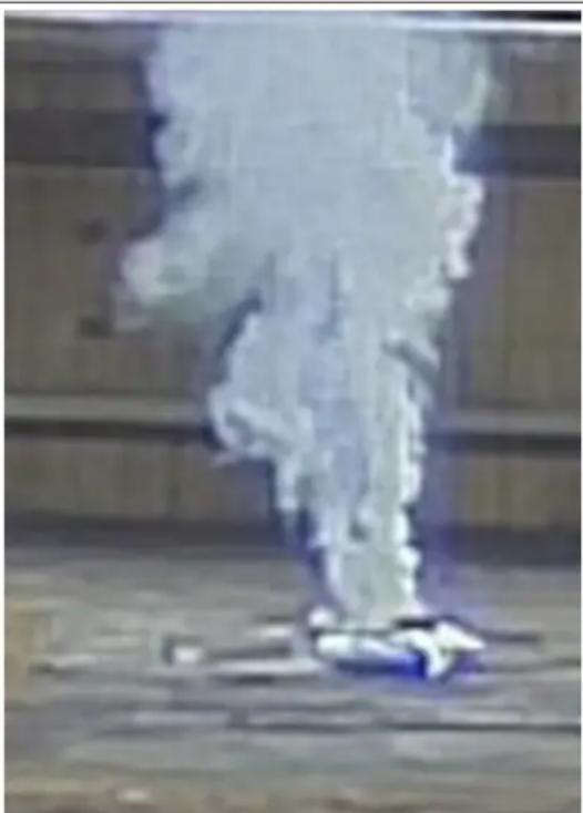
natural_image
A person standing on a wooden floor emitting smoke or vapor, with no visible text or symbols.In regular conditions with an equal colored background, smoke is visible when the smoke density exceeds 40%.
In case of a background with high color saturation (e.g. deep blue) or a high background intensity or strong contrasts or very strong color contrast (e.g. black and white or blue and yellow) behind the smoke region the required smoke density can increase up to 90% before smoke is detected.

Notice!
All smoke detection properties are influenced by wind. For more details, see the Planning Manual.
4 Installation
| i | Notice!Do not expose the image sensors to direct sunlight.Do not obstruct the free flow of air around the camera. |
| i | Notice!Avoid backlight.Backlight can disturb the video-based fire detection algorithm. |
| i | Notice!Minimum Illumination required.To ensure the proper functioning of the video-based fire detection algorithm, a minimal illumination of 2 lx is required. If the illumination is less than 2 lx, an additional IR illumination is required. |
| i | Notice!Avoid obstructions in the field of view!Covered fires cannot be detected correctly. An unobstructed view of the detection area is necessary. |
| i | Notice!Avoid image regions with continuous upward motion.Continuous upward motion might lead to false alarms. |
| i | Notice!Make sure the camera is firmly mounted.Camera shake might lead to false alarms. Avoid vibrations of the camera and the camera environment. |
4.1 Requirements
When installing the camera, take the following points into account or have prepared the following:
- Computer and its IP address
- Download of newest Firmware / Software tools
- IP range of the network
- Plan sketches with camera position and designation
- Planning of the camera setting (size flame/ smoke, verification time + sensitivity if available)
- Recording
- Required work equipment for configuration:
- POE power supply + camera connection
– Computer with admin rights and Internet access - Download the latest firmware and tools (e.g. Configuration Manager)
- IP address range change on Computer
- A multimeter for testing the relay output
- Analog monitor and cable for camera alignment
4.2 Preparation in the office
We recommend that you prepare the installation in the office, as you can carry out many tasks here that are not recommended under time pressure and possibly on lifting platforms etc.
We recommend that you carry out the following steps in advance:
- Labeling camera + cardboard
Unpack the camera and label it and the box with installation location and the later IP address.
- Use PoE to power the camera.
- Start the Configuration Manager and change the IP address of the camera according to the plan. You can perform steps 3 to 8 using the Configuration Manager.
- Change the passwords for the users "service", "live", "user". If necessary, you can also create additional users.
- Check that the firmware version installed on the camera is up to date and update it if necessary. Always test the fire detection after updating to the latest firmware.
- Set the current time and date and assign a camera name if required.
- Change the fire detection settings as planned.
- Adjust the recording settings if necessary.
4.3 On-site commissioning
- Install the camera at the planned installation site
- Adjust the opening angle as planned and align the camera.
- Focus the camera image on the lens and then use the lens wizard to fine-tune the focus.
- Optional: If necessary, adjust the settings for fire detection to the conditions on site
- Document all settings and screenshots of the viewing area in the customer documentation.
4.4 Lens mounting

Notice!
Only use the supplied lens or approved lenses.
Do not use other lenses. A reliable functioning of the product cannot be guaranteed with other lenses.
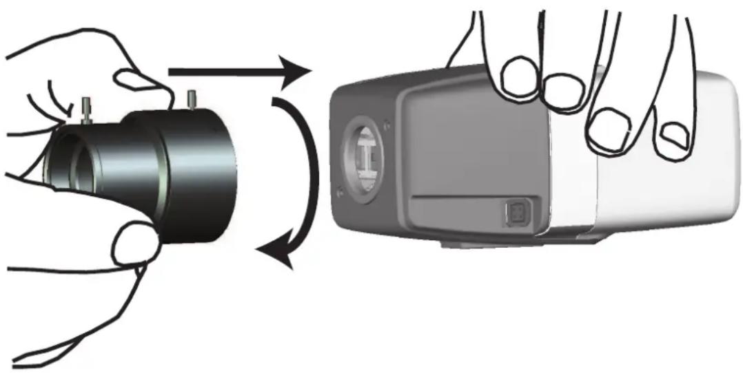
natural_image
Illustration of a hand holding a camera module being twisted, showing the motion of the lens (no text or symbols present)To attach the lens to the camera:
- Remove the sensor protection cap from the camera.
- Remove the protection cap from the lens.
- Screw the lens onto the camera.
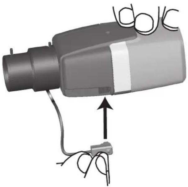
natural_image
Diagram of a handheld device with wires and a small plug, showing no text or symbolsPlug the lens connector into the camera (it automatically detects the type of lens).
| Pin DC iris lens | |
| 1 Damp - | |
| 2 Damp + | |
| 3 Drive + | |
| 4 Drive - |
4.5 Camera mounting
Mounting variants
Due to the provided mounting bracket, the camera can be easily mounted. There are three main mounting variants to install the camera.
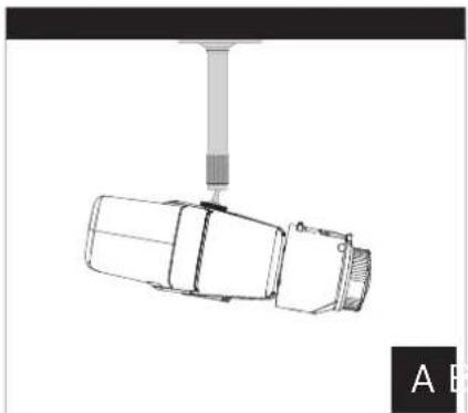
natural_image
Technical line drawing of a mechanical component with a cylindrical shaft and base, labeled 'A B' (no text or symbols on the diagram itself)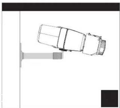
natural_image
Top-down line drawing of a car parked near a vehicle (no text or symbols)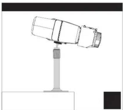
natural_image
Technical line drawing of a mechanical device mounted on a stand (no text or symbols)Figure 4.1: Mounting variants
| A Ceiling mount | |
| B Wall mount | |
| C Stand mount |
Chose the right mounting variant for your application and mount the device according to the following options:
- Install the mounting bracket.
- Attach the camera to the bracket and tighten the camera lock ring.
- Adjust the angle of the camera to set the field of view.
- Tighten the mounting bracket lock ring to fix the camera in the desired position.
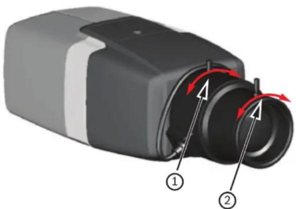
4.6 Setting the field of view
After the camera is mounted to the surface, the field of view can be set.
natural_image
3D diagram of a camera lens assembly with labeled parts (1 and 2), showing internal components and red directional arrows indicating motion or flow.| 1 focal length | |
| 2 focus |
The field of view must be set manually according to the following steps:
- Manually adjust the focal length on the lens to obtain the required field of view.
- Manually adjust the focus on the lens to obtain the sharpest image possible.
- Focus the image in the center of the monitored area to avoid blurring as much as possible.
The camera lens has a motorized automatic back focus to adjust the focus at a later time via the camera menu.
4.7 Wiring of the camera
Connection to Ethernet via PoE Ethernet cable

Notice!
Use only PoE approved devices.
The camera is intended to be powered via a STP Category 5e cable in a Power-over-Ethernet (PoE) network environment. This is the default power supply.
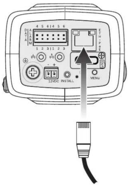
- Connect the camera to a 10/100 Base-T network.
- Use STP Category 5e cable with RJ45 connectors (the camera network socket is Auto MDIX compliant).
√ The LEDs beside the Ethernet connection indicate network connection (green lit) and IP traffic (orange flashing).
Auxiliary 12 V DC power supply

Caution!
Use only a +12 VDC power supply as an auxiliary power source.
The auxiliary power supply unit must be isolated from earth.

Caution!
The Low Voltage power supply unit must comply with EN/UL 60950. The power supply must be a SELV-LPS unit or a SELV - Class 2 unit (Safety Extra Low Voltage - Limited Power Source).
The camera can be supplied with a power supply in case of missing PoE feature of the network or for redundancy reasons.
Connect an approved power supply unit with a rated supply voltage of 12 VDC as follows:
- Strip back 7 mm (0.28 in) of insulation on the power supply cable (must be 16-28 AWG, UL 14-30 AWG).
- Loosen the screws of the supplied 2-pole connector and insert the stripped wires, then tighten the screws again.
- Insert the 2-pole connector into the camera power socket.
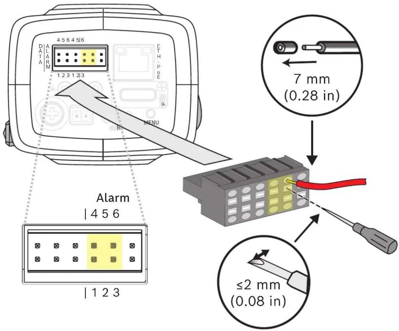
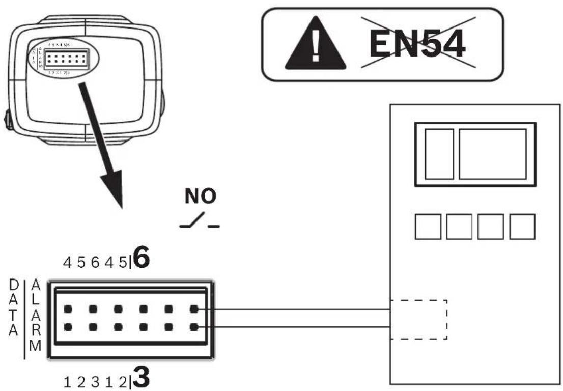
4.8 Alarm output
The alarm contact assignment is shown in the figure below:
Alarm out
Use the alarm output for switching external devices such as lamps or sirens.
Alarm output switching capability:
- Max. voltage 30 VAC or +40 VDC. Max. 0.5 A continuous, 10 VA.
| Pin Alarm socket | |
| 3 Alarm out | |
| 6 | |
The maximum wire diameter is 18-28 AWG, UL 16-28 AWG for both stranded and solid; cut back 7 mm (0.28 in) of insulation.
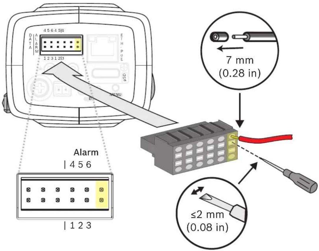
4.9 Alarm input
The alarm contact assignment is shown in the figure below:
Alarm in:
Use the alarm input to connect external alarm devices such as door contacts or sensors:
- TTL logic, +5 V nominal, +40 VDC max, DC coupled with 50 kOhm pull-up to +3.3 V.
- Configurable as active low or active high.
A zero potential make-contact or switch can be used as the actuator (use a bounce-free contact system).
| Pin Alarm socket | |
| 1 Alarm in 1 | |
| 4 Ground | |
| Pin Alarm socket | |
| 2 Alarm in 2 | |
| 5 Ground | |
The maximum wire diameter is 18-28 AWG, UL 16-28 AWG for both stranded and solid; cut back 7 mm (0.28 in) of insulation.
5 Camera integration
The video-based fire detection can be easily integrated into the network environment of the customer. There are several possibilities to connect the camera. Various combinations are possible. The individual customer network properties determine the performance and scalability of the system.
 | Camera |
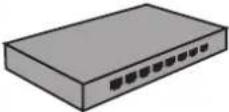 | Network switch, PoE-ready |
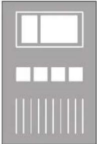
 | Client PC |
 | Video Recording Manager (VRM) |
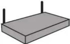 | Router |
 | Internet |
  | Monitoring Center |
 | Fire alarm control panel |
| Mobile devices |
5.1 Local Area Network
Due to the IP-based camera, the integration of the video-based fire detection into the network of the customer is easy. There are a lot of opportunities regarding to scalability and enlargement of the network.
flowchart
graph LR
    A["USB Device 1"] --> C["Switch"]
    B["USB Device 2"] --> C["Switch"]
    C --> D["Desktop Computer"]
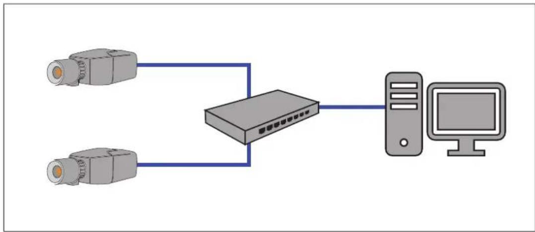
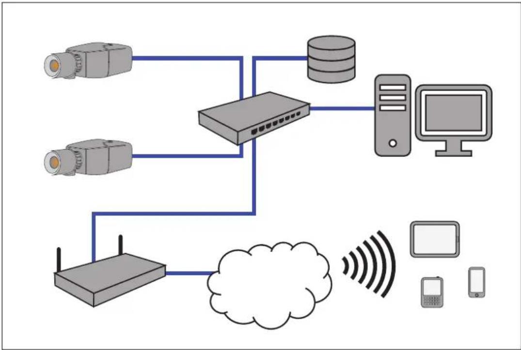
5.2 Local Area Network with recording solution
Recording and archiving functionality in the network can be realized by a video recording manager (VRM). Fire cause analysis and traceability due to legal matters are only two examples of a recording solution.
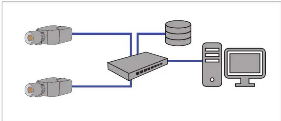
flowchart
graph TD
    A["Camera 1"] --> C["Server"]
    B["Camera 2"] --> C
    C --> D["Database"]
    D --> E["Desktop"]
5.3 Monitoring Center
In a monitoring center, alarms can be verified to call the fire brigade and to take care of additional rescue measures.
flowchart
graph TD
    A["Device 1"] --> B["Router"]
    C["Device 2"] --> B
    D["Device 3"] --> B
    B --> E["Server"]
    B --> F["Cloud Storage"]
    F --> G["Desktop"]
    F --> H["Headphones"]
    style A fill:#f9f,stroke:#333
    style C fill:#f9f,stroke:#333
    style D fill:#f9f,stroke:#333
    style E fill:#ccf,stroke:#333
    style F fill:#ccf,stroke:#333
    style G fill:#ccf,stroke:#333
    style H fill:#ccf,stroke:#333
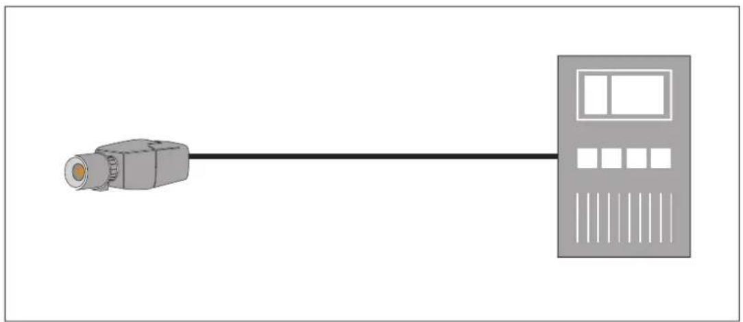
5.4 Fire Alarm Control Panel
AVIOTEC IP starlight 8000 can be connected to the a fire alarm control panel. The alarm will be triggered by the relay output of the camera.

Notice!
No direct connection to fire services in EN54 compliant installations.
Authorities can allow a connection to fire services after verifying alarms in a monitoring center.
natural_image
Diagram of a device with a connector and control panel connected by a line (no text or symbols)Connection to a fire alarm control panel
The alarm output of the camera can be connected to a fire alarm control panel.
The camera alarm output is triggered by a relay that is normally open. In case of alarm the relay is closed.
See the documentation of the individual manufacturer for further information about the connection to a fire alarm control panel.
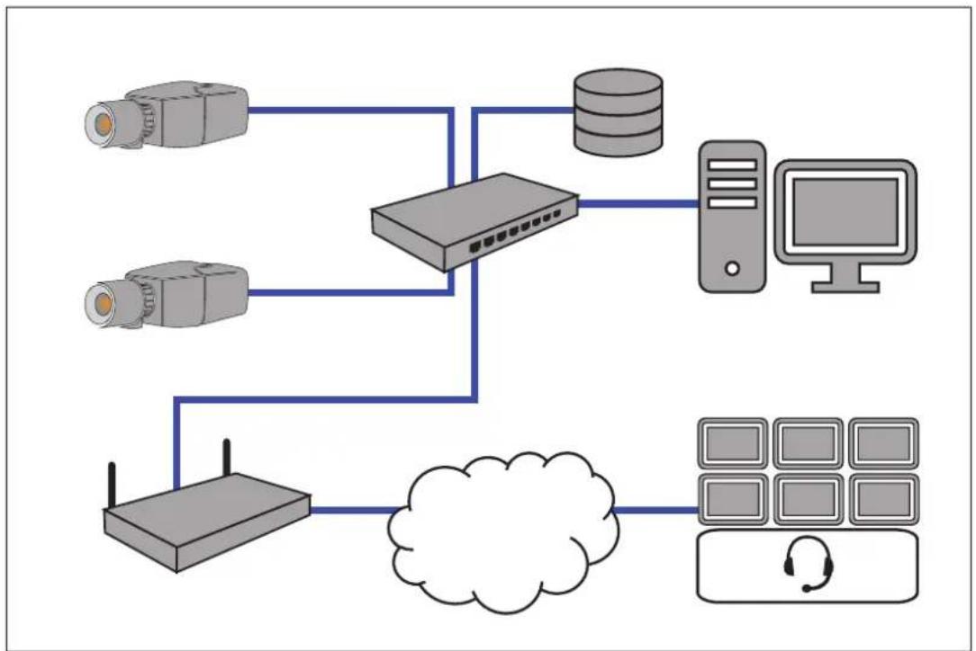
5.5 Mobile Devices
Another advantage of the network integration of the video-based fire detection is the expandability to mobile devices, such as tablets or smartphones.
flowchart
graph TD
    A["Camera"] --> B["Router"]
    C["Camera"] --> B
    D["Camera"] --> B
    E["Server"] --> B
    F["Computer"] --> B
    G["Cloud"] --> B
    H["Mobile Phone"] --> B
    I["Smartphone"] --> B
6 Access to the device
The unit must have a valid IP address and a compatible subnet mask to operate on your network.
If the network has a DHCP server for the dynamic assignment of IP addresses, select On or On plus Link-Local to automatically accept the DHCP-assigned IP address.
If no DHCP server is available select On plus Link-Local to automatically assign a Link-Local (Auto-IP) address.
For certain applications, the DHCP server must support the fixed assignment between IP address and MAC address, and must be appropriately set up so that, once an IP address is assigned, it is retained each time the system is rebooted.
6.1 Access via web interface
Please note that an Internet Explorer with activated ActiveX plugin is required. The plugin is available at https://downloadstore.boschsecurity.com/.
- Open the Internet Explorer.
- Enter the IP address of the camera to get access to the web interface.
6.2 Configuration Manager
You can also get access to the camera via Configuration Manager available at https://downloadstore.boschsecurity.com/.
7 Adjustment of detection settings
The standard settings of the video-based fire detection will be sufficient for the most customer environments. Nevertheless, there are many ways to adapt the flame and smoke detection to the requirements of the customer. The detection settings of the fire detection can be changed in the configuration menu:
- Go to Configuration and navigate to Alarm.
- Select Fire detection.

Notice!
The VCA settings affect the Fire detection settings.
You can create three individual profiles for Fire detection. These different Fire detection profiles can also be used in a scheduled configuration (see Setting up VCA):
- Silent VCA
- profile #1 (renameable in VCA settings)
- profile #2 (renameable in VCA settings)
General and special settings for Fire detection are selectable. Anytime you change the settings, confirm with Set to apply these changes.
If you want to abort, just click on another menu option, for example Audio Alarm.
The Intelligent Video Analytics functions and the video-based fire detection settings can be changed during operation and will immediately become effective.
7.1 General settings
Following settings change the detection algorithm generally.
Flames
The default setting of the flame size is 1.1% of the picture width.
Verification time [s] of the flame detection can be set to 4, 8, 12 or 16 seconds. The default value is 8 seconds. Small values cause faster detection (higher risk of false alarms), larger values decrease false alarms.
Smoke
The default setting of the smoke size is 1.6% of the picture width.
Verification time [s] of the smoke detection can be set from 10 to 30 seconds. The default value is 15 seconds. Small values cause faster detection (higher risk of false alarms), larger values decrease false alarms.
Sensitivity
In case of false alarms, you can use a software slider to adapt the value Sensitivity for flame and smoke to your specific needs. The following table shows the different settings:
| Sensitivity | |||
| low mid high | |||
| Smoke – High contrast | and colored objects in the video image cause false alarms. (recommendation: set also Verification time [s] to 20s)– Slow moving objects (e.g. cranes, slow vehicles, automatic doors) cause false alarms. (recommendation: set also Verification time [s] to 20s) | Default setting If no moving objects are expected. | |
| Flames Blinking lights | or fans cause false alarms. (recommendation: set also Verification time [s] to 12s) | Default setting If no moving objects and no blinking lights are expected. | |
7.2 Adjustments of image regions

Notice!
There is no fire detection in privacy defined masks created in the Intelligent Video Analytics.
Masking
Due to the different areas of application of the camera, false alarms may be the result in individual customer environments. Algorithm disturbing elements which have an appearance similar to flames and smoke, for example ascending steam of a machine, must be excluded from the detection area.
Customized areas can be defined in the picture of the camera. These individual masks for flame and smoke detection deactivation allow individual adaption to the application of the customer. Overlapping of masks is possible.
There are several possibilities to exclude picture areas from the smoke and flame detection:
- Add masks separately for flame, smoke or both.
- Individually adjust the verification time in a mask.
- Let the system automatically generate masks from the alarm memory by automasking.
Automasks support the user to adapt the system to his individual application area. Once the camera is powered, every upcoming alarm will be stored into the volatile alarm memory.
Generally it is advantageous to wait a certain period of time before using the automasking feature for the first time. It depends on the special customer environment, whether there will be false alarms or not. With automasking, detection disturbing areas in the picture can automatically be masked out by the system. If there is no alarm, no automask will be generated. The user can change the size of the automasks to minimize the masked out area.
The system is limited to 16 automasks (8 masks for smoke detection and 8 masks for flame detection). Changes of the flame and smoke detection settings require renewing the automasks.
Add mask
You can define individual areas (16 in total) in which the detection can be deactivated or modified. These masks can easily be added to the picture area.
To add a mask, perform the following steps:
- Click on the button Add mask.
A rectangle will appear in the middle of the picture area.
In Properties you can select the following options:
Ignore flames
The detection of flames are disabled in the mask. This is shown by a crossed out flame icon at the bottom right-hand corner.
Ignore smoke
The detection of smoke are disabled in the mask. This is shown by a crossed out smoke icon at the bottom right-hand corner.
Ignore flames and smoke
The detection of flames and smoke are disabled in the mask. This is shown by a crossed out smoke and a crossed out flame icon at the bottom right-hand corner.
Verification time smoke
The following settings (in seconds) are possible to assign an individual verification time
for each mask: 5 ... 120. A clock icon with a small smoke plume is displayed at the bottom right-hand corner.
Verification time flames
The following settings (in seconds) are possible to assign an individual verification time for each mask: 4 / 8 / 12 / 16. A clock icon with a small flame is displayed at the bottom right-hand corner.
- Change the size and shape of the rectangle to your specific needs.
- Move the mask to the desired area in the picture.
- Select Set to confirm the changes.
Automask

Notice!
All automasks stored in the volatile alarm memory of the camera are lost when the supply voltage is interrupted or switched off. Automasks that already have been saved will remain unaffected.

Notice!
If you change the settings of Verification time [s], it is necessary to renew the automasks.
- Navigate to Configuration > Alarm > Fire detection.
- Select Automask
The system automatically generates predefined masks from the alarm memory. The automasks are illustrated as rectangles with red dashed border. - Adjust the automask to your specific needs.
If it is necessary, you can add individual masks (Add mask). - Select Set to confirm the changes.
√ Automasks were added to the system.
Reset user interface

Notice!
All determined masks in the user interface will be deleted! Only automasks remain stored in the alarm memory and can be regenerated.
If you want to reset the user interface to standard values:
- Click on Defaults.
- Press OK to confirm.
√ The system resets the user interface for fire detection to the standard settings.
Delete Automasks

Notice!
Delete automasks if you changed the camera position, zoom, point of view or after a fire. Also delete automasks if the spatial arrangement of objects in the detection area has changed fundamentally.
To delete the automasks for Flame detection from the alarm memory:
- Navigate to Fire detection > Flames > Detection.
- Select Off and press Set.
- Select On and press Set.
√ Automasks for Flame were deleted.
To delete the automasks for Smoke detection from the alarm memory:
- Navigate to Fire detection > Smoke > Detection.
- Select Off and press Set.
- Select On and press Set.
√ Automasks for Smoke were deleted.
7.3 Adaptation to the lighting situation
The lighting can vary greatly from application to application. You can adjust the following settings to the lighting situation.
7.3.1 General lightning settings
There are three different settings in the camera menu that are important for lighting in relation to video-based fire detection:
Go to Camera > Installer Menu > Day/Night. You can select the following settings:
Auto - the camera switches the IR cut-off filter on and off depending on the scene illumination level. Select this setting if you have continuous natural or artificial light in your application and at last 2 lx are available or you have artificial light and redundant IR lightning.
If the illumination is lower than 2 lx, the camera switches to monochrome mode. In this mode, it may take longer until a reliable flame detection is possible.
Monochrome - the IR cut-off filter is removed, giving full IR sensitivity. Select this setting if you have continuous IR lightning in your application.
Color - the camera always produces a color signal regardless of light levels. Select this setting if you have continuous natural or artificial light in your application.
7.3.2 Flickering
Select the mode for automatic light-level control:
- Fluorescent 50 Hz
- Fluorescent 60 Hz
- Outdoor
7.4 Expert Mode (not VdS certified)

Warning!
Configuration changes that you make in Expert Mode differ from the parameters that have been tested and secured by Bosch Sicherheitssysteme GmbH, and are not covered by VdS certification. This means it is your responsibility to ensure the reliability of the fire detection and, if necessary, fire tests. Sicherheitssysteme GmbH assumes no liability for the reliability of fire detection in case of configuration changes in Expert Mode.
7.4.1 Color
Brightness (0...255)
Adjust the brightness with the slider from 0 to 255.
Contrast (0...255)
Adjust the contrast with the slider from 0 to 255.
Saturation (0...255)
Adjust the color saturation with the slider from 0 to 255.
White balance
- Basic auto mode allows the camera to continually adjust for optimal color reproduction using an average reflectance method. This is useful for indoor light sources and for colored LED light illumination.
- Standard auto mode allows the camera to continually adjust for optimal color reproduction in an environment with natural light sources.
- Sodium lamp auto mode allows the camera to continually adjust for optimal color reproduction in an environment with sodium vapor light sources (street lighting).
- Dominant color auto mode takes into account any dominant color in the image (for example, the green of a football pitch or of a gaming table) and uses this information to obtain a well balanced color reproduction.
- In Manual RGB mode, the Red, Green, and Blue gain can be set manually to a desired position.
Apply white balance
Click Hold to put ATW on hold and save the current color settings. The mode changes to manual.
RGB-weighted white balance
In an auto mode, RGB-weighted white balance can be switched On or Off. When On, additional fine tuning of the automatic color reproduction can be made with the R, G and B weight sliders.
R-gain
In Manual RGB white balance mode, adjust the red gain slider to offset the factory white point alignment (reducing red introduces more cyan).
G-gain
In Manual RGB white balance mode, adjust the green gain slider to offset the factory white point alignment (reducing green introduces more magenta).
B-gain
In Manual RGB white balance mode, adjust the blue gain slider to offset the factory white point alignment (reducing blue introduces more yellow).
Note:
It is only necessary to change the white point offset for special scene conditions.
Default
Click Default to set all video values to their factory setting.
7.4.2 ALC
ALC mode
Select the mode for automatic light-level control:
- Fluorescent 50 Hz
- Fluorescent 60 Hz
- Standard
ALC level
Adjust the video output level (-15 to 0 to +15).
Select the range within which the ALC will operate. A positive value is more useful for low-light conditions; a negative value is more useful for very bright conditions.
ALC - average vs. peak
The ALC - average vs. peak slider configures the ALC level so that it controls mainly on scene average level (slider position - 15) or on scene peak level (slider position +15). Scene peak level is useful for capturing images that contain car headlights.
Exposure
Automatic exposure
Select to let the camera automatically set the optimum shutter speed. The camera tries to maintain the selected shutter speed as long as the light level of the scene permits.
- Select the Maximum shutter [s] for automatic exposure. (The values available depend on the value set for the Sensor mode in the Installer Menu).
Fixed exposure
Select the Fixed shutter [s] for fixed exposure. (The values available depend on the value set for the ALC mode).
Day/Night
Auto - the camera switches the IR cut-off filter on and off depending on the scene illumination level.
Monochrome - the IR cut-off filter is removed, giving full IR sensitivity.
Color - the camera always produces a color signal regardless of light levels.
Day-to-night switchover
Adjust the slider to set the video level at which the camera in Auto mode switches from color to monochrome operation (-15 to +15).
A low (negative) value means that the camera switches to monochrome at a lower light level. A high (positive) value means that the camera switches to monochrome at a higher light level.
Night-to-day switchover
Adjust the slider to set the video level at which the camera in Auto mode switches from monochrome to color operation (-15 to +15).
A low (negative) value means that the camera switches to color at a lower light level. A high (positive) value means that the camera switches to color at a higher light level.
(The actual switch-over point might change automatically to avoid instable switching.)
Note:
To ensure stability when using IR illuminators, use the alarm interface for reliable Day/Night switching.
7.4.3 Enhance
Backlight compensation
Select Off to switch off backlight compensation.
Select On to capture details in high-contrast and extremely bright-dark conditions.
Contrast enhancement
Select On to increase the contrast in low contrast conditions.
Intelligent Defog
Select this to activate the automatic intelligent defog feature. This feature continuously adjusts image parameters to provide the best picture possible under foggy or misty conditions.
Intelligent Dynamic Noise Reduction
Select On to activate intelligent Dynamic Noise Reduction (DNR) which reduces noise based on motion and light levels.
Sharpness level
Adjusts the Sharpness level between -15 and +15. A low (negative) value makes the picture less sharp. Increasing sharpness brings out more detail. Extra sharpness can enhance the details of license plates, facial features and the edges of certain surfaces but can increase bandwidth requirements.
Temporal noise filtering
Adjusts the Temporal noise filtering level between -15 and +15. The higher the value, the more noise filtering.
Spatial noise filtering
Adjusts the Spatial noise filtering level between -15 and +15. The higher the value, the more noise filtering.
7.5 Relay settings

Notice!
The alarm output is only configurable for flame or smoke alarms. Forwarding alarms coming from Intelligent Video Analytics is not possible.
The camera includes a built-in relay that switches in case of a flame or a smoke alarm. The relay is switched during the alarm and returns to its initial state after the alarm.
You can configure the switching behavior of the output:
Go to Alarm > Interfaces > Alarm Outputs
Idle state
- Under Idle state select the desired initial state of the relay.
- Select from the following options:
Closed: the relay is normally closed.
Open: the relay is normally open.
Output name
An individual name can be assigned to the relay. The name is shown on the button. The Live page can also be configured to display this individual name.
Toggle
You can click the button to switch the alarm output manually (for example, for testing purposes). A green check mark appears to indicate that the relay switches.

Notice!
Check carefully the toggle settings before you continue.
Press Set to apply the settings.
8 Use cases
Fire detection in combination with VCA functionality offers different use cases. These four use cases are described below.
8.1 Fire detection only
This is the standard setting of the camera. You can choose this standard option if different fire detection profiles and profile scheduling are not necessary for your application. In case you need to adapt the general fire detection settings, please refer to chapter Adjustment of detection settings, page 33.
8.2 Fire detection and VCA profiles
If you want to use fire detection and video surveillance functions, e.g. detect unauthorized access, you can create two individual VCA profiles. Please be aware that only one VCA profile can be active at a time. The fire detection profile depends on the corresponding VCA profile and these are always active simultaneously. For example if you choose VCA profile (Fire #1), the Fire detection profile (Fire #1) is enabled. If you choose VCA profile (Fire #2), the Fire detection profile (Fire #2) is enabled.
| Silent VCA(VCA not configurable) | VCA profile (Fire #1) | VCA profile (Fire #2) | |
| Fire detection (Silent VCA) | linked(see Fire detection only, page 42) | x | x |
| Fire detection (Fire #1) | x linked x | ||
| Fire detection (Fire #2) | x x linked |
How to change the VCA profiles:
- Go to Configuration > Alarm > VCA .
- In VCA configuration choose the corresponding profile.
- Set up and modify the VCA profile (refer to the IVA documentation for more information and IVA settings).
- Go to Configuration > Alarm > Fire detection.
- Set up the corresponding fire detection profile (see Fire detection only, page 42).
8.3 Scheduled fire detection
In many industrial applications you have a lot of movement during the day and very little movement at night. A scheduled configuration allows you to link a VCA profile with the days and times at which the video content analysis is to be active. Schedules can be defined for weekdays and for holidays.
-
Go to Configuration > Alarm > VCA .
-
In the VCA configuration drop-down list, select Scheduled.
Link any number of 15-minute intervals with the VCA profiles for each day of the week. Moving the mouse cursor over the table displays the time below it. This aids orientation.
- Click the profile to link in the Time periods field.
- Click in a field in the table, hold down the mouse button and drag the cursor over all the periods to be assigned to the selected profile.
- Use the right mouse button to deselect any of the intervals.
- Click Select All to link all time intervals to the selected profile.
- Click Clear All to deselect all of the intervals.
- When finished, click Set to save the settings in the device.
Define holidays on which a profile should be active that are different to the standard weekly schedule.
- Click the Holidays tab. Any days that have already been selected are shown in the table.
- Click Add. A new window opens.
- Select the desired date from the calendar. Select several consecutive calendar days by holding down the mouse button. These will later be displayed as a single entry in the table.
- Click OK to accept the selection. The window closes.
- Assign the individual holidays to the VCA profiles, as described above.
Deleting Holidays
Delete defined holidays at any time:
- Click Delete. A new window opens.
- Click the date to delete.
- Click OK. The item is deleted from the table and the window closes.
- The process must be repeated for deleting additional days.

Notice!
If you have not yet created any fire detection profiles (see Fire detection and VCA profiles, page 42), you must do so and go to Configuration > Alarm > Fire detection.
Refer to
– Fire detection and VCA profiles, page 42
8.4 External trigger to switch fire detection mode
This configuration allows you to change the VCA profile / fire detection profile when triggered by an event.
In the VCA configuration drop-down list, select Event triggered.
The camera offers two alarm inputs (see chapter Alarm input, page 24).
-
In Configuration select Trigger.
-
Select a physical alarm (alarm input) as a trigger, choose Alarm input 1 or Alarm input 2.
-
In Trigger active select the VCA configuration that is to be enabled via an active trigger.
A green check mark to the right of the list field indicates that the trigger is active.
- In Trigger inactive select the VCA configuration that is to be activated if the trigger is not active.
A green check mark to the right of the list field indicates that the trigger is inactive.
Delay [s]
Select the delay period for the reaction of the video content analysis to trigger signals. The alarm is only triggered after a set time interval in seconds has elapsed and then only if the triggering condition still exists. If the original condition has been restored before this time interval elapses, the alarm is not triggered. A delay period may be useful in avoiding false alarms or frequent triggering. During the delay period, the Silent VCA configuration is always enabled.
Go to Interfaces, select Alarm Inputs and adapt the corresponding alarm input to your needs.
![BOSCH FCS-8000-VFD - Delay [s] - 1](/content/2026/05/889163/images/7ebac55727d5a7caf81c3fea34fbca3c9397ddc76a97616973b297cb07e4fefe.jpg)
Notice!
If you have not yet created any fire detection profiles (see Fire detection and VCA profiles, page 42), you must do so and go to Configuration > Alarm > Fire detection.
One example would be an environment with cleaning cycles. A key switch can be used as an external trigger to switch between the different fire detection profiles.
Refer to
- Alarm input, page 24
9 Troubleshooting
The following issues can be solved in the detection settings (Configuration > Alarm > Fire detection).
9.1 False Alarms
9.1.1 Quick solution to solve false alarms
A fast way to identify and solve region-stable false alarms in the camera image is automasking. The system automatically generates predefined masks from the alarm memory.
Navigate to Configuration > Alarm > Fire detection.
- Select Automask.
- Select Set to confirm the changes.
Refer to
- Automask, page 36
9.1.2 False alarms under 4 seconds concerning the whole detection area
In this case the general settings of the fire detection have to be adjusted.
| Problem Solution | |
| Short false alarms for smoke detection. Increase | the duration of smoke detection.(Smoke>Verification time [s]) |
| Short false alarms for flame detection. Increase | the duration of flame detection.(Flames >Verification time [s]) |
9.1.3 False alarms at small constant areas
Individual image areas are affected and have to be adjusted.
| Problem Solution | |
| Objects cause flickering motion, e.g. shadow of a flag in the wind. | Mask out the disturbing image area (for flame).Flame detection will be deactivated in this mask. |
| Continuous motion in the picture causes false alarms, e.g. escalators. | Mask out the disturbing image area (for smoke).Smoke detection will be deactivated in this mask. |
| Temporary motion causes false alarms, e.g. roller shutter. | Mask out the disturbing image area (). Smoke detection will be delayed in this mask. |
9.1.4 Vibrations at the camera site
| Problem Solution | |
| Vibrations are transferred to the camera. Avoid | vibrations at the camera site. |
| Camera picture is trembling. Make sure the camera is firmly mounted. | |
| The camera position changed because of vibrations. | Move the camera to its initial position and check the field of view. Make sure the camera is firmly mounted. |
9.2 No alarm transmission
Problem: Alarms are visible in the web browser but there is no alarm transmission to the video client.
Solution:
- Check network connection and settings (Configuration -> Network)
- Check relay connection and settings (Alarm > Interfaces > Alarm Outputs)
- Check fire detection settings (Configuration > Alarm > Fire detection)
- Check the video client settings
9.3 No fire detection
– Problem: No detection of fire.
- Solution:
- Check fire detection settings (Configuration > Alarm > Fire detection)
- Check mask settings
- Check privacy mask settings
- Check the focus of the lens (Configuration -> Camera -> Installer Menu -> Open... ->)
- Check obstructions in the field of view
- Check the detection area
- Check minimum/maximum distance to fire
9.4 Image quality
Interference of the camera image
Small image areas or the whole image area are affected by interferences.
| Problem Solution | |
| Artificial light, e.g. fluorescent light, causes flickering of the camera image. | Go to Installer Menu > ALC mode and change to fluorescent mode. |
9.5 Camera
If a fault cannot be resolved, please contact your supplier or system integrator, or go directly to Customer Service.
The version numbers of the internal firmware can be viewed on a service page. Please note this information before contacting Customer Service.
-
In the address bar of your browser, after the unit IP address, enter: /version for example: 192.168.0.80/version
-
Write down the information or print out the page.
The camera offers a variety of configuration options. Therefore, check that it works properly after installation and configuration. This is the only way to ensure that the camera will function as intended in the event of an alarm.
Your check should include the following functions:
- Can you connect to the camera remotely
- Does the camera transmit all the data required?
- Does the camera respond as desired to alarm events?
- Is it possible to control peripheral devices, if necessary?
The camera has four LEDs on the rear panel:
- Two LEDs indicate the camera status (red for error; green for OK)
- Two LEDs (green and orange) beside the network connection indicate the LAN and PoE status
| No OSD messages appear. Special Video SDK is required. Video management software from third parties does not use the SDK. |
The ping command can be used to check the connection between two IP addresses. This allows testing whether a device is active in the network.
- Open the DOS command prompt.
- Type ping followed by the IP address of the device.
If the device is found, the response appears as "Reply from ... ", followed by the number of bytes sent and the transmission time in milliseconds. Otherwise, the device cannot be accessed via the network. This might be because: - The device is not properly connected to the network. Check the cable connections in this case.
- The device is not correctly integrated into the network. Check the IP address, subnet mask, and gateway address.
10 Maintenance
10.1 Cleaning
It is generally sufficient to use a dry cloth for cleaning, but a moist lint-free cloth or leather shammy may also be used.
Do not use liquid cleaners or aerosol cleaners.
It is important to keep the lens clean to ensure optimum performance. Dust, grease, or fingerprints should be removed from the lens surface. When cleaning the lens, take extra care not to damage the special coating used to reduce light reflections.
- Remove dust with a blower-brush or grease-free soft brush.
- Wipe water drops off the lens with a clean soft lint-free cloth and dry the lens surface.
- Use special lens cleaning paper or cloth treated with lens cleaning fluid to gently wipe off any remaining dirt (wipe spirally from the lens center towards the edge).
10.2 Repair

Notice!
Never open the casing of the unit
The unit does not contain any user-serviceable parts. Refer all repairs to suitable qualified specialists.
10.3 Reset
Use the factory reset button to restore the unit to its original settings. Any changes to the settings are overwritten by the factory defaults. A reset may be necessary, for example, if the unit has invalid settings that prevent it from functioning as desired.
10.4 Maintenance intervals

Notice!
Maintenance and inspection work should be carried out regularly and by trained personnel.
The following inspections are recommended:
| Testing Inspection frequency | |||
| Item to inspect annually | quarterly regularly | ||
| Visual check of the mounting | X | ||
| Visual check for damage | X | ||
| Item to inspect annually quarterly regularly | |||
| Check the camera lens for pollution and damage | X | ||
| Functional check X | |||
| Check of the video image | X | ||
11 Technical data
| Algorithm Overview | ||
| Min. detection size for Smoke, standard setting(% of picture width) | 1.6 | |
| Smoke speed(% of picture height /s) | 0.7 - 16 | |
| Min. Smoke density (%) 40 | ||
| Min. detection size for Flame, standard setting(% of picture width) | 1.1 | |
| Min. illumination level (lx) 2 | ||
| Min. illumination level with IR illumination (lx) 0 | ||
| Environmental | ||
| Operating Temperature -20°C to +50°C (-4°F to 122°F) | ||
| Storage Temperature -30°C to +70°C (-22°F to +158°F) | ||
| Operating Humidity 20% to 93% RH | ||
| Storage Humidity up to 98% RH | ||
| Input/output | ||
| Analog video out SMB connector, CVBS (PAL/NTSC), 1 Vpp, 75 Ohm | ||
| Audio line in 1 Vrms max, 18 kOhm typical, | ||
| Audio line out 0.85 Vrms at 1.5 kOhm typical, | ||
| Audio connectors 3.5 mm mono jack | ||
| Alarm input 2 inputs | ||
| Alarm input activation +5 VDC nominal; +40 VDC max. (DC-coupled with 50 kOhm pull-up resistor to +3.3 VDC)(< 0.5 V is low; > 1.4 V is high) | ||
| Alarm output | 1 output | |
| Alarm output voltage | 30 VAC or +40 VDC max.Maximum 0.5 A continuous, 10VA (resistive load only) | |
| Ethernet | RJ45 | |
| Data port | RS-232/422/485 | |
| Local storage | ||
| Internal RAM | 10 s pre-alarm recording | |
| Memory card slot | Supports up to 32 GB microSDHC / 2 TB microSDXC card.(An SD card of Class 6 or higher is recommended for HD recording) | |
| Local storage | |
| Recording Continuous recording | ring recording. alarm/events/schedule recording |
| Mechanical | |
| Dimensions (W x H x L) 78 x 66 | x140 mm (3.07 x 2.6 x 5.52 inch) without lens |
| Weight 855 g (1.88 lb) without lens | |
| Color RAL 9006 Metallic Titanium | |
| Tripod Mount Bottom and top 1/4-inch 20 UNC | |
| Sustainability PVC free | |
| Network | |
| Protocols IPv4, IPv6, UDP, TCP | HTTP, HTTPS, RTP/RTCP, IGMP V2/V3, ICMP, ICMPv6, RTSP, FTP, ARP, DHCP, APIPA (Auto-IP, link local address), NTP (SNTP), SNMP (V1, V3, MIB-II), 802.1x, DNS, DNSv6, DDNS (DynDNS.org, selfHOST.de, no-ip.com), SMTP, iSCSI, UPnP (SSDP), DiffServ (QoS), LLDP, SOAP, DropboxTM, CHAP, digest authentication |
| Encryption TLS1.0/1.2, AES128 | AES256 |
| Ethernet 10/100 Base-T, auto-sensing, half/full duplex | |
| Connectivity Auto-MDIX | |
| Interoperability ONVIF Profile S; ONVIF Profile G | |