
SP-15 AT-29 - Wall mount Grunkel - Free user manual and instructions
Find the device manual for free SP-15 AT-29 Grunkel in PDF.


| Product Type | Wall Mount |
| Brand | Grunkel |
| Model | SP-15 AT-29 |
| Compatible Screen Size | 27" to 46" |
| Maximum Load | 25 kg (55 lbs) |
| VESA Mounting Pattern | 400 mm x 400 mm |
| Tilt Range | 3° up to 15° down |
| Pan/Swivel Range | Up to 180° |
| Profile Distance | 7.0 cm to 28.5 cm |
| Material | Black metal frame |
| Included Components | Mount (x1), vertical bar (x1), horizontal bar (x1), hardware kit, cable clip, instruction manual |
| Hardware Kit Contents | M6 x 63 lag bolts (x2), lag bolt washers (x2), concrete anchors (x2), M4 x 12 screws (x4), M8 x 12 screws (x4), M6 watermelon washers, M8 washers (x4), M6 x 10 screws (x4), M6 x 13 x 1.5 washers (x4), S10 socket wrench (x1) |
| Tools Required | Phillips screwdriver, ratchet/driver with 13 mm socket, electric drill, 3 mm and 8 mm drill bits, stud finder, level |
| Installation Surface | Drywall (must be into wood stud) or concrete |
| Safety Features | Safety warning for children under 8, requires adult supervision for installation |
| Maintenance | Periodic cleaning with dry cloth; inspect screws regularly |
| Warranty | Not specified, but includes guarantee card |
| Disposal | Do not dispose as household waste; follow WEEE directive 2002/96/EC |
Frequently Asked Questions - SP-15 AT-29 Grunkel
User questions about SP-15 AT-29 Grunkel
0 question about this device. Answer the ones you know or ask your own.
Ask a new question about this device
Download the instructions for your Wall mount in PDF format for free! Find your manual SP-15 AT-29 - Grunkel and take your electronic device back in hand. On this page are published all the documents necessary for the use of your device. SP-15 AT-29 by Grunkel.
USER MANUAL SP-15 AT-29 Grunkel
natural_image
Mechanical assembly with black metal frame and mounting bracket (no text or symbols visible)natural_image
A couple smiling while looking at a document together, with cardboard boxes in the background (no visible text or symbols)
natural_image
Modern flat-screen TV displaying a large wave crashing against turquoise ocean waves, with no visible text or symbols.
natural_image
Modern kitchen blender with black handle and blue control knob against purple background (no text or symbols)
natural_image
White microwave oven with control knobs and a black door, set against an orange background (no text or symbols visible)
natural_image
White portable electric heater with mesh insulation and wheels (no visible text or symbols)
natural_image
Black octop oven with control knobs and a clear glass interior, set against an orange background (no text or symbols visible)
natural_image
Product photo of a white and red electric vacuum cleaner with control buttons (no visible text or symbols)
natural_image
White rectangular toaster with a black button on the front, set against a solid purple background (no text or symbols visible)
natural_image
Modern stainless steel coffee maker with handle and spout against a solid purple background (no text or symbols visible)
natural_image
Metallic coffee maker with black handle against a solid yellow background (no text or symbols visible)
natural_image
Exterior view of a modern office desk fan with black and white blades against a blue background (no text or symbols visible)
natural_image
Black hair dryer with pink background (no text or symbols visible)
natural_image
White and maroon electric iron with a steam iron, displayed against a solid green background (no text or symbols visible)
natural_image
White kitchen grater with black handle and side slots, set against a solid purple background (no text or symbols visible)DESCUBRE TODO LO QUE PODEMOS HACER POR TI EN
www.grunkel.com
GRACIAS POR ESCOGER ESTE PRODUCTO GRUNKEL
This instruction manual is an accurate reproduction of the specifications, operation and look of the product you have just bought, except for typographical, print or translation errors. The specifications, operation and features of this product are subject to change without further notice.

ANTES DE PONER EL PRODUCTO EN FUNCIONAMIENTO
natural_image
Technical diagram showing two views of a mechanical component with arrows indicating direction (no text or symbols)
¡ATENCIÓN!
- Please, read carefully the entire instruction manual before using it.
- Pay special attention to the safety indications.
- Keep this instruction manual. If you hand over this appliance to another person, these instructions must be also be transferred.
- Keep also the guarantee card, purchase ticket or invoice. If possible, keep the original box with all the accessories included for future inquiries.

WARNING!
THE INFORMATION RELATED TO MAXIMUM LOAD AND MAXIMUM SIZE SUPPORTED BY THIS MOUNT DEPENDS ON EACH TV MODEL INDIVIDUALLY. THE TRUTHFULNESS AND SAFETY OF THE PROVIDED INFORMATION ARE THE SOLE RESPONSIBILITY OF THEIR RESPECTIVE MANUFACTURERS, AND ARE NOT ASSOCIATED WITH THIS PRODUCT IN ANY WAY.
SpecificationsContent
Mount (x1)
Vertical bar (x1)
Horizontal bar (x1)
Instruction manual (x1)
Hardware kit (x1)
Cable clip (x1)
Display Size: 27" to 46"
Maximum Load: 25 kg
Mounting Pattern: 400 mm x 400 mm
Tilt Range: 3° up to 15° down
Pan/Swivel Range: up to 180°
Profile: 7.0 cm to 28.5 cm
General safety instructions
Read these instructions before you begin. If you are unsure of any part of the process, contact a professional contractor or installer for assistance. Improper installation can result in injury or damage.
The wall or mounting surface must be capable of supporting the combined weight of the mount and the display; if not, the structure must be reinforced.
grunkel
Locate pipes, wires, or any other hazards in the wall where you wish to install the mount before drilling.
Safety gear and proper tools must be used. Failure to do so can result in injury or damage.
Two people are recommended for installation. Do not attempt to lift a heavy display without assistance.
Follow all instructions and recommendations regarding adequate ventilation and suitable locations for mounting your display. Consult the owner's manual for your particular display for more information.

CAUTION: This wall mount is intended for use only with the maximum weight of 25 kg (55 lbs). Use with heavier than the maximum weights indicated may result in instability causing possible injury.
Tools required
Phillips Head Screw Driver
Ratchet or Driver with 13 mm (1/2") Socket
Electric or Portable Drill
3 mm (1/8") Drill Bit and Stud Finder for Drywall Installation
8 mm (5/16") Masonry Bit for Concrete Installation
Level
Hardware kit
(A) M6 x 63 Lag Bolt (x2) (G) M6 Watermelon (mm)
(B) Lag Bolt Washer (x2) (H) M8 Washer (x4)
(C) Concrete Anchor (x2) (I) M6 x 10 Screw (x4)
(D) M4 x 12 Screw (x4) (J) M6 x 13 x 1.5 Washer (x4)

(F) M8 x 12 Screw (x4)

Installation
Part 1A – Mounting to the Wall (Drywall)

IMPORTANT: For safety reasons, this mount must be secured to a wood stud capable of supporting the combined weight of the mount and display. Do not mount to drywall alone.
Use a high quality stud finder to locate a stud where you wish to install your mount. Mark both edges of the stud to help identify the exact center.

NOTE: You must use the center of the stud to avoid cracking or splitting the wood during installation.
Place the mount against the wall over the marked studs. Make sure it is level.
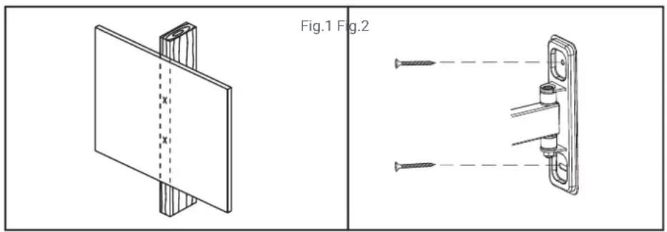
While another person holds the mount in place, mark two locations as shown for securing the mount to the wall (see Fig.1).
Set the mount aside and drill a 3 mm (1/8") pilot hole at each marked location.
Place the mount against the wall over the drilled holes, making sure the arrow on the mount points up. Attach the mount to the wall using the lag bolts (A) and lag bolt washers (B) provided (see Fig. 2). Do not over-tighten these bolts and do not release the mount until all bolts are in place. Ensure that the mount remains level after all bolts are secured.
Parte 1B - Mounting to the Wall (Concrete)

IMPORTANT! For safety reasons, the concrete wall must be capable of supporting the combined weight of the mount and the display. The manufacturer takes no responsibility for failure caused by walls of insufficient strength.
Place the mount against the wall in the desired location. Make sure it is level.
While another person holds the mount in place, mark two locations as shown in the illustration for securing the mount to the wall (see Fig. 3).
Set the mount aside and drill a 8 mm (5/16") hole at each marked location. Remove any excess dust from the holes.
Insert a concrete anchor (C) into each hole so that it is flush with the concrete surface (see Fig. 4). A hammer can be used to lightly tap the anchors into place if necessary.

NOTE: If the concrete wall is covered by a layer of plaster or drywall, the concrete anchor must pass completely through the layer to rest flush with the concrete surface.
Parte 2 – Attaching the Mount to the Display

IMPORTANT! Use extra care during this part of the installation. If possible, avoid placing your display facedown as it may damage the viewing surface.

NOTE: This mount comes with a selection of different screw diameters and lengths to accommodate a wide variety of display models. Not all of the hardware in the kit will be used. If you cannot find the appropriate screw size in the kit provided, consult the manufacturer of your display for more information.
Determine the correct diameter of screw to use by carefully trying one of each size (M4, M6 and M8) from the hardware kit. Do not force any of the screws – if you feel resistance stop immediately and try a smaller diameter screw.
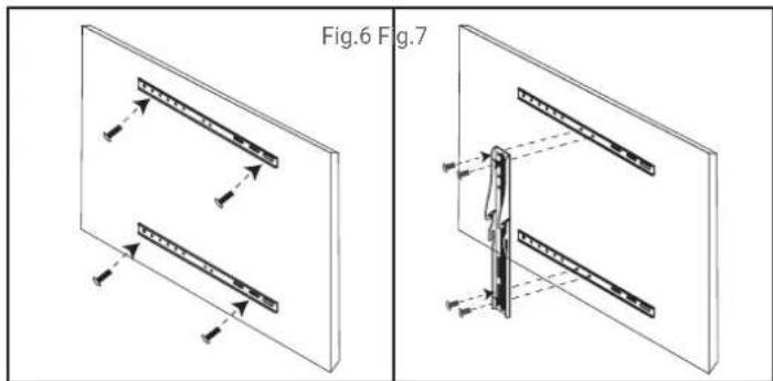
Attach the horizontal bars to the back of your display using the screws identified in step 1 as shown in the illustration (see Fig. 6). If you are using the M6 screws you will need to use the M6 washers (G). If you are using the M8 screws you will need to use the M8 washers (H). Make sure to use the same mounting holes on each horizontal bar.
Attach the vertical bar to the horizontal bar using four of the M6 x 10 screws (I) and M6 x 13 x 1.5 washers (J) as shown in the illustration. The vertical bar should be centered on the horizontal bars as closely as possible and orientated exactly at shown (see Fig. 7).
natural_image
Technical diagram showing two views of a mechanical component with arrows indicating direction (no text or symbols present)Parte 3 – Final Assembly
Make sure the top screws on either side of the mount are loose, but do not remove these screws.
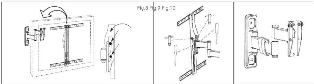
With the help of another person, carefully lift your display and hook it onto the mount (see Fig. 8). Do not release the display until the vertical bar has securely hooked onto the mount.
Set the tilt to the desired angle, and then tighten the top screws on either side of the mount (see Fig. 9).
Attach the cable clip found in the hardware kit to the lower mount arm and route your cables as needed (see Fig. 10).
Operation and adjustment
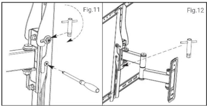
To change the tilt angle of your display, hold the display firmly in place and loosens the top screws on either side of the mount. Set the display to the desired position, and then re-tighten the screws (see Fig. 11). Do not release the display until the screws are fully tightened and never fully loosen or remove these screws.

CAUTION: Be careful not to pinch cables or fingers whenever you are changing the tilt angle, or when handling hinges and screws.
Swivel adjustments can be made by grasping the display firmly and moving it to the desired position. Be careful that fingers or cables do not get pinched when moving the mount.
Level correction adjustments can be made by simply rotating the display in the needed direction. If it is too difficult to move the display or if the display does not stay in position once moved, adjust the tension of the two nuts located behind the front of the mount using the S10 socket wrench (K) provided in the hardware kit (see Fig. 12). Do not fully loosen or remove these nuts.
Periodically clean your mount with a dry cloth. Inspect all screws and hardware at regular intervals to ensure that no connections have become loose over time. Re-tighten as needed.

CAUTION!
CHILDREN UNDER 8 YEARS OLD SHOULD NOT USE NOR CLEAN THIS APPLIANCE WITHOUT THE SUPERVISION OF AN ADULT. NEITHER CAN BE USED NOR CLEAN BY PEOPLE WITH REDUCED PHYSICAL, MENTAL OR SENSORIAL CAPABILITIES, WITHOUT EXPERIENCE OR KNOWLEDGE CONCERNING THE USE OF THE APPLIANCE, OR WITHOUT HAVING RECEIVED PROPER TRAINING UNDER DIRECT SUPERVISION FROM AN EXPERIENCED PERSON RESPONSIBLE FOR THEIR SAFETY.
Product disposal
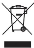
Regulation regarding waste from electronic appliances according to RAEE 2002/96/EC. This symbol means the appliance can not be treated as regular domestic waste; it must be returned to the distributor, handed over the corresponding electronic product collection point or delivered to the collection point empowered for such purpose, so its components are recycled and not mixed within domestic waste.
You can also contact your local waste collection service, so it can be collected and treated accordingly following the environment protection instructions, or to receive proper information about the steps to follow for the correct disposal of the appliance.
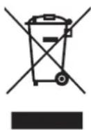
The correct disposal of an appliance implies avoiding negative consequences for both environment and health. A proper disposal allows to save a significant amount of energy and resources. As a reminder of the necessity of disposing the appliances separately, the product displays the symbol of a crossed out garbage bin.
The image contains no text or characters.
(F) Parafuso M8 x 12 (x4)


(K) Chave de caixa S10 (x1)(E) Parafuso M6 x 12
Instalação
Parte 2 - Monte o suporte na TV

natural_image
Technical diagram showing two views of a mechanical component with arrows indicating direction (no text or symbols present)Operação e ajuste

ATENÇÃO!
CRIANÇAS MENORES DE 8 ANOS DE IDADE NÃO DEVEM USAR OU LIMPAR ESTE APARELHO SEM A SUPERVISÃO DE UM ADULTO. TAMBÉM NÃO PODE SER USADO OU LIMPO POR PESSOAS COM CAPACIDADES FÍSICAS, MENTAIS OU SENSORIAIS REDUZIDAS, SEM EXPERIÊNCIA OU CONHECIMENTO DE SEU USO, OU QUE NÃO TENHAM RECEBIDO TREINAMENTO ADEQUADO SOB A SUPERVISÃO DIRETA DE UMA PESSOA CAPACITADA.
Eliminar a unidade
- GRACIAS POR ESCOGER ESTE PRODUCTO GRUNKEL
- ANTES DE PONER EL PRODUCTO EN FUNCIONAMIENTO
- ¡ATENCIÓN!
- WARNING!
- SpecificationsContent
- General safety instructions
- grunkel
- Tools required
- Hardware kit
- Installation
- Parte 1B - Mounting to the Wall (Concrete)
- Parte 3 – Final Assembly
- Operation and adjustment
- CAUTION!
- Product disposal
- Instalação
- Operação e ajuste
- ATENÇÃO!
- Eliminar a unidade
Brand : Grunkel
Model : SP-15 AT-29
Category : Wall mount