
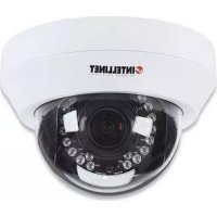
NFC30-IRWG - Surveillance Camera Intellinet - Free user manual and instructions
Find the device manual for free NFC30-IRWG Intellinet in PDF.


| Product Type | IP Surveillance Software (NVR) |
| Model | NFC30-IRWG (Intellinet) |
| Supported Cameras | IP cameras (UPnP or manual add); up to 64 channels (CIF) |
| Video Compression | MPEG-4, MJPEG, H.264 |
| Recording Modes | Continuous, motion-triggered, event-triggered; schedule configurable |
| Playback | Search by date/time, cue points, speed control, zoom, image saving/printing |
| Motion Detection | General motion with adjustable sensitivity, interval, and zone definition |
| PTZ Control | Pan, tilt, zoom, focus, preset points, patrol (4 groups) |
| Smart Guard Events | Motion, digital input, system events; actions include on-screen display and sound alarm |
| Remote Access | Live streaming server, remote playback server, web view (IE) |
| System Requirements | CPU: Intel Core 2 Duo (CIF: Pentium D 930); RAM: 1 GB; OS: Windows 2000/XP Pro SP2/2003/Vista |
| Storage Calculation | Provided for various resolutions, frame rates, and compression (GB/channel/day) |
| User Management | Multi-user accounts with configurable privileges |
| Backup | Video and log backup to local drive or CD; playback on any Windows PC |
| Language | English (manual in PDF, 87 pages) |
Frequently Asked Questions - NFC30-IRWG Intellinet
User questions about NFC30-IRWG Intellinet
0 question about this device. Answer the ones you know or ask your own.
Ask a new question about this device
Download the instructions for your Surveillance Camera in PDF format for free! Find your manual NFC30-IRWG - Intellinet and take your electronic device back in hand. On this page are published all the documents necessary for the use of your device. NFC30-IRWG by Intellinet.
USER MANUAL NFC30-IRWG Intellinet
IP Surveillance System
User's manual
IP Surveillance system
Table of Contents
TABLE OF CONTENTS
TABLE OF CONTENTS ...... 1
SYSTEM REQUIREMENT....3
INSTALLATION 4
- MAIN CONSOLE....12
1.1 Start 14
1.2 Information Window:....16
1.3 PTZ Camera Control:....16
1.4 On Screen Menu....18
- PLAYBACK....19
2.1 Information Window:....21
2.2 Audio Volume Control: 21
2.3 Screen Division: 21
2.4 Browse Mode: 21
2.5 Date Time: 21
2.8 Save Image ....23
2.9 Print....24
2.10 Backup 24
2.11 Log Viewer 26
- SCHEDULE....28
3.1 Day Mode 29
3.2 Load Preset Modes ......29
3.3 Insert a New Schedule Manually....30
3.4 Copy Schedule ....31
3.5 Week Mode....31
3.6 Adjust the Scheduled Setting....32
3.7 Encoding Option Panel....33
- GUARD....34
4.1 Event ......35
4.2 Action ....38
- CONFIGURATION ....39
5.1 Setting – General......40
5.2 Setting - Camera....43
5.3 Setting - I/O Device....47
5.4 Setting - PTZ Config....48
Table of Contents
5.5 Setting - User Account....49
5.6 Setting – Monitor Display ....49
5.7 Save/ Load Configuration....50
5.8 Log Viewer ....51
5.9 Backup ....53
5.10 Network Service ....58
5.11 About Main Console....66
-
REMOTE LIVE VIEWER....67
6.1 Setup Panel....68
6.2 Show Camera(s) On the Display Screen 70 -
WEB VIEW ....72
7.1 Server IP....72
7.2 Remote Live Viewer ....73
7.3 Remote Playback....73
APPENDIX A – SYSTEM LOADING ....74
APPENDIX B - STORAGE REQUIREMENT TABLE (VGA)....76
APPENDIX C - STORAGE REQUIREMENT TABLE (MEGA)......82
System Requirement
SYSTEM REQUIREMENT
| Total FPS at CIF | 480~640 3 | 60~480 240~ | 360 120~240 | 0~120 | |
| CPU | Intel Core 2 Duo | Intel Pentium D 930 | Intel Pentium D 930 | Intel P4 2.8 GHz | Intel P4 2.4 GHz |
| RAM 1 GB 1 GB 1 GB 512 MB 512 MB | |||||
| Mother-board | Intel 945 or 965 chip, Intel Chipset recommended | ||||
| Display | ATI Radeon 9200, nVIDIA GeForce FX-5200, Intel 945 / 965, or above (ATI recommended) | ||||
| Ethernet 100 BaseT or Above, Gigabit LAN Recommended | |||||
| Hard Disk 80 GB or above | |||||
| OS MS | Windows 2000 / XP Pro SP2 / 2003 / Vista | ||||
Quick Start INSTALLATION
Step 1: Insert the Installation CD.
Step 2: Run Setup.exe from the CD-ROM driver/ directory to install.

setup
Setup.exe
Macrovision Corporation
Step 3: Check the option "I accept the terms of the license agreement".

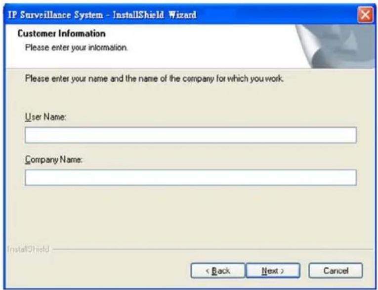
Step 4: Please enter your name and the company name for which you work.
IP Surveillance system
Quick Start
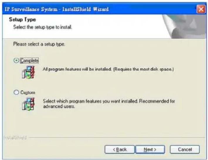
COMPLETE SETUP TYPE:
Install all program features into the default directory.
Check the option "Complete". All program features will be installed. [Require the most disk space.]
Press the "install" to start the installation.

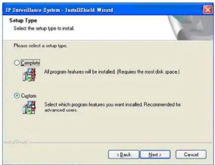
Custom Setup Type:
Install the system to a preferred directory. Or select whichever feature(s) you wish to install.
Check the option "Custom". Select which program features you want to install. This is recommended for advanced users.
Quick Start
Select folder where setup will install files.

Select the features setup will install.
Hint: For example, select only Playback for installation. Install and use only these features on multiple remote sites at home or anywhere with a PC.

Press "Finish" to finish the installation.

IP Surveillance system
Quick Start
Execute the Main Console

Enter the password you like into the edit box and enter again at the edit of Password Confirm. And then press "OK". Now enjoy our Intelligent Surveillance Solution.

Quick Start
Quick Start
Install IP camera(s)
Step 1: Setup the IP camera(s) following by the instruction manual provided by the manufacturer.
Step 2: Check the network between the IP camera(s) and the system.
Step 3: Add the IP camera(s) to the system following below steps.
ADD IP CAMERA(S)
Step 1: Go to Start > All Programs > IP Surveillance > Main Console.
Step 2: Type in user name and password and log on to the system.
Step 3: In Main Console, go to Config > Setting to obtain the Setting panel.
Step 4: Go to Camera tab.
If your IP cameras support UPnP. Follow step 5. Otherwise, follow step 8.
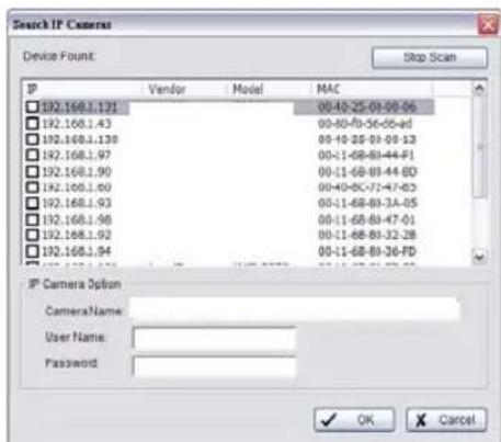
Step 5: Click "Search" to search for the IP cameras that are available at this point.
Note: Search function just support the IP cameras with UPnP supported.
Step 6: Select one of the IP cameras that are available; check the option and enter the username and password.
Step 7: Click OK to add the camera.
Step 8: Click "Insert" to insert the IP cameras.

IP Surveillance system
Quick Start
Step 9: Enter the IP address or domain name (check the "Use DNS" option), Http Port, Username, and Password.
Step 10: Click "Auto Detect"
Step 11: Click OK to add the camera.
Step 12: Click OK to exit the Setting panel.

Set Schedule
Step 1: Go to Start > All Programs > IP Surveillance > Main Console.
Step 2: Type in user name and password and log on to the system.
Step 3: In the Main Console, go to Schedule.
Step 4: By default, when inserting a camera to the system, the recording schedule is automatically set to be 24 hours a day, always record.
Step 5: Click Configure on the selected camera schedule or double click on any schedule bar to modify the recording mode.
Step 6: When satisfied with the schedule setting, click OK to update the recording schedule.
Step 7: Click OK again to go back to the Main Console. page-9

Quick Start
Set Smart Guard
Step 1: Go to Start > All Programs > IP Surveillance > Main Console.
Step 2: Type in user name and password and log on to the system.
Step 3: In the Main Console, go to Guard.
Step 4: Select a camera and then click on "Insert Event."
Step 5: Select General Motion as the event type, click OK.
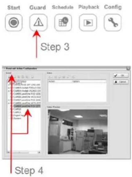
Step 6:
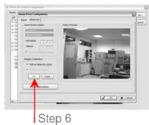
In the Alarm Event Configuration panel, set the detection zone as all, and then click OK to exit the panel.
Step 7: Click OK to go back to the Main Console.

START RECORDING & SMART GUARD
Step 1: Go to Start > All Programs > IP Surveillance > Main Console.
Step 2: Type in user name and password and log on to the system.
Step 3: In the Main Console, go to Start.

IP Surveillance system
Quick Start
Step 4: Click on "Start Recording Schedule" and "Start Smart Guard System" to initiate the two functions.
Step 4
PLAYBACK
Step 1: Go to Start > All Programs > IP Surveillance > Main Console.
Step 2: Type in user name and password and log on to the system.
Step 3: In the Main Console, go to Playback.
Step 4: In the Playback window, click on the Date Time Icon.
Step 5:
In the time table, recorded files are displayed in color bars. Highlight any color bars to select playback section. Click OK to return to Playback Console.
Step 6:
The recorded files are ready to view now.


1. Main Console
1. Main Console

This is the main operation system - to activate, schedule recording, setup smart guard and configure system setting.
IP Surveillance system
1. Main Console
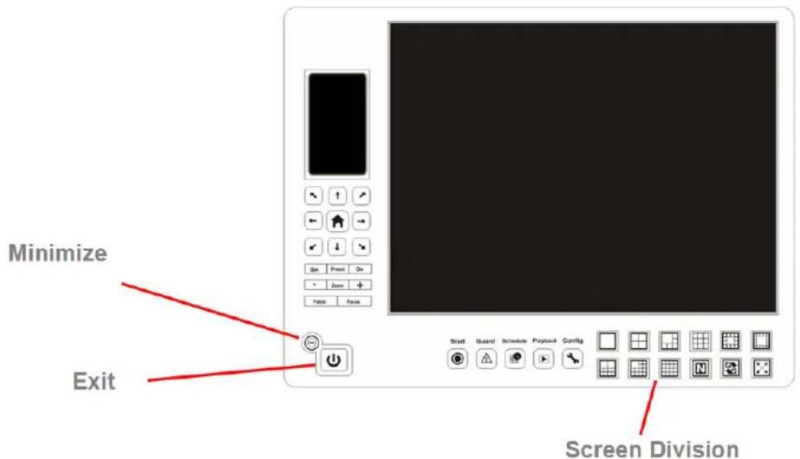
EXIT: Shut down the Surveillance System or log out current user.
MINIMIZE: Minimize the Main Console window.

SCREEN DIVISION: Allocate the sub-screen display by clicking on the desired layout icon. To switch to single camera display, double click on a particular sub-screen. Double click on the screen again to regain previous screen division layout.

Divide into 1 screen(s)
Divide into 4 screen(s)
Divide into 6 screen(s)
Divide into 9 screen(s)
Divide into 10 screen(s)
Divide into 13 screen(s)
Divide into 16 screen(s)
Divide into N screen(s)
Divide into 13 screen(s)
Divide into 17 screen(s)
Switch to Full screen
Rotate all screens
1. Main Console
1.1 Start

START: Click on the Start icon and select from the drop down menu to activate/deactivate: (a) Recording Schedule System, (b) Smart Guard System, or (c) Counting Application. Select Start/Stop Monitor All to activate/deactivate all the functions at once.
Note: When activating any of the monitor functions, system considers the current screen status as normal. Therefore, if you want to, for example, detect Missing Object, be sure the object needed to be protected is in its position at the moment you click Start button.
IP Surveillance system
1. Main Console

PLAYBACK: Click on the icon to get Playback Console. You can watch recorded video, search recorded video, adjust image of the stored data, save video/pictures, print images, check log information and event records, and set up recording function configuration. See 2.Playback for detail.
SCHEDULE: Organize recording time schedule and setup recorder configuration. See 3.Schedule for detail.
GUARD: Add/edit type(s) of events that you want to detect; setup reaction(s) responding to events. See 4.Guard for detail.
CONFIG: Select from the drop down menu to modify general setting, save/ load configuration settings, start counting application, access log viewer and backup files, or setup network services. See 5.Configuration for detail.
1. Main Console

1.2 Information Window:
Display date, time, free HD space, CPU temperature, fan speed, and customized text. To customize Information about window's setting, go to Config > General Setting > General
1.3 PTZ Camera Control:
Control the movement of PTZ cameras. With cameras that support PTZ control, you can move, zoom, patrol, adjust the focus, and set preset points of the cameras.
1.3.1 Preset/ Go:
Adjust the camera view until you are satisfied. Click on the Set icon and set up the view as the preset point 01. Adjust the camera view again and set up the preset point 02. Repeat the process until finish setting up all preset points. You can enter any names you like to instead of the preset point 01, preset point 02, preset point 03.
Click on the Go icon and view the result of your setting.
1.3.2 Zoom: Click on the + and – signs to zoom in and zoom out the view.
1.3.3 Focus: You can select to have the camera focused near or far. To focus near means objects that are closer will be clearer than the objects that are further away. On contrast, to focus far means objects that are further will be clearer than the objects that are closer.
IP Surveillance system
1. Main Console
Click on the Focus icon and select auto focus if you want the system to decide the focus point for you.
1.3.4 Patrol: Go to Patrol > Set Patrol to obtain the Patrol Setup dialog. From the left window, select the cameras that you would like to have in the patrol group. Align the cameras in order in the right window and adjust the time. Rename the group name if you want. After completing the setup, check the Active option, and then click OK.
You can setup up to four groups of auto patrol. To start or stop, click on the Patrol icon in the Main Console, and select Start Patrol or Stop Patrol.

1. Main Console
1.4 On Screen Menu

Right click on the camera screen and get the On Screen Menu, from which you can enable move, enable digital PTZ, and connect/ disconnect the camera.
1.4.1 Enable Move: With cameras that support PT function, by selecting the enable move function, you may adjust the camera's view by clicking on the display screen. To cancel this function, right click on the screen and select Disable Move.
Note: You can only work on current camera after clicking Enable Move.
1.4.2 Enable Talk: With cameras that support two-way audio, you may select enable talk to utilize the function.
1.4.3 Connect/ Disconnect: Right click on the display screen and select Connect/ Disconnect to modify the connecting status of the camera.
1.4.4 Show Camera: Select the camera to be displayed from the Show Camera Menu.
1.4.5 Delete Camera: Click on Delete Camera to remove a camera from the display screen. This does not delete the camera from the setting list.
1.4.6 Enable Digital PTZ: To enable the PTZ functions of the camera, select the Enable digital PTZ option. When enable digital PTZ, we can use mouse wheel to zoom in and zoom out on the camera.
Note: Enable Digital PTZ is the option function in IP+ software not in IP software
1.4.7 Snapshot: Select the snapshot function to capture a specific video image immediately. You have the options to copy the image to the clipboard or to save it.
1.4.8 Manual Record: Start recording video by selecting manual record.
1.4.9 Toggle Full Screen: To view a specific channel with full screen.
IP Surveillance system
2. Playback
2. Playback

Watch the recorded video, view and/or search for unusual events and recorded system information.
2. Playback

MINIMIZE: Minimize the Playback console.
EXIT: Shut down the Playback console.
SCROLL BAR: Indicate the status of the playing video; drag it to where you want to review.
CONTROL: Play, pause and stop the video.
CUE: When playing video, click on the Cue In/ Cue Out icon at where you want to set as the starting/ ending point of a saved video clip. The Cue In and Cue Out time will be displayed on the Playback Information Window once they are set.
SPEED: Control the speed of the playing video. Click + to speed up and - to speed down.
ZOOM: Zoom in and zoom out. Get a close up view of the recorded video; move to the spot you want to view by dragging the screen.
IP Surveillance system
2. Playback
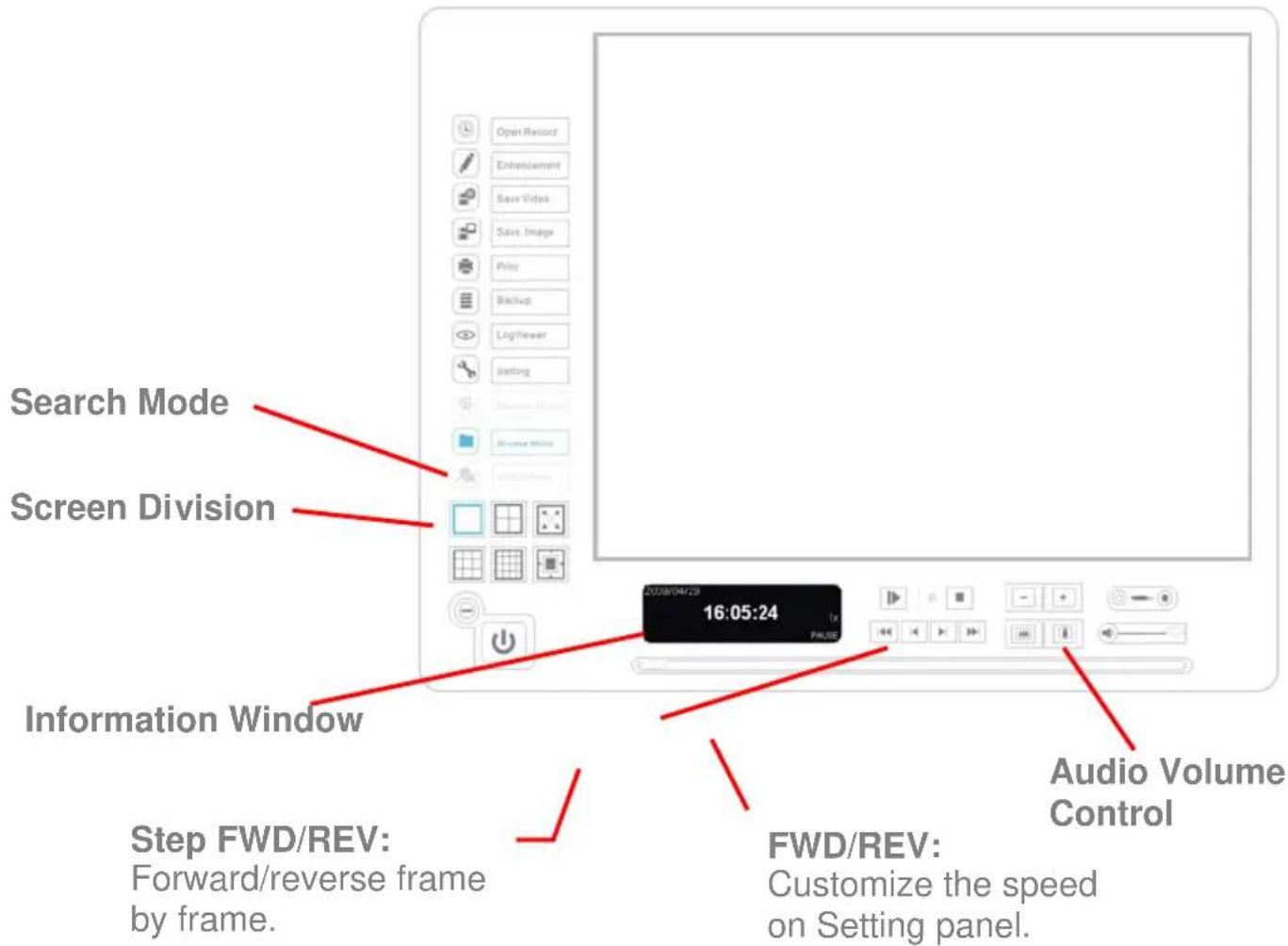
2.1 Information Window:
Display video date and time, current video status, cue in/ out points' time, and speed.
2.2 Audio Volume Control:
Adjust the sound level.
2.3 Screen Division:
Allocate the sub-screen display by clicking on the desired layout icon. To switch to single camera display, double click on a particular sub-screen. Double click on the screen again to regain previous screen division layout.
2.4 Browse Mode:
Play the recorded video.
2.5 Date Time:
Click on Date Time button to access the Date-Time Panel and withdraw the video record that you want to review.
2. Playback
2.5.1 Date Time Panel Withdraw the records:

Step 1: From the window at the top left of the Date-Time Panel, select the date you want to check, and you will see red/green lines show on the time table implying available recorded video.
Step 2: You can select the video clip you want to review by left-clicking and dragging to highlight the time period. Besides using the time-table, you can also indicate the time period of video that you want to see by using the Start Time and End Time in Date Time Period section.
Step 3: In Select Camera(s) section, select the camera(s)/channel(s) from which you want to see the video. You can select all cameras by clicking Select All button.
Step 4: Check Enable Preview to get the preview of the video you select.
Step 5: Click OK when you are done with the settings.
IP Surveillance system
2. Playback
2.6 Enhancement
2.6.1 General Setting: Check the option and chose whether you want to apply the setting to all the channels or only to those currently shown on the screen.
2.6.2 Filter Setting
Visibility: Check the option and adjust the gamma value of the image to enhance the image and make it cleaner.
Sharpen: Check the option to activate the function. Move the slider control to the right to sharpen the image, to the left to soften it.
Brightness: Check the option to activate the function. Move the slider control to the right to make the image brighter.
Contrast: Check the option to activate the function. Move the slider control to the right to increase contrast.
Grey Scale: Check the option to show the record in grey scale mode so the image displays in black and white.
2.7 Save Video
Step 1: Click on the display screen to choose the camera display that you want to save as a video clip.
Step 2: Set up the cue in and cue out points; the cue in and cue out time will show on the information window.
Step 3: Click Save Video icon, choose the folder where you want to save the file at, enter the file name and click SAVE. You may export (i.e. save) the record with both audio and video or video only.
Step 4: Choose the compression format and then save the video.
2.8 Save Image
Step 1: Click on the display screen to choose the camera display from which you want to save pictures.
2. Playback
Step 2: Click Save Image button when the image you want is shown on the screen. You may click Pause to freeze the video, use Step Forward/ Step Backward function to find the picture(s) that you want to save.
Step 3: Choose the folder and the format of image (BMP or JPEG) you prefer and then click save.
Note: You may skip step 3 by pre-setting a folder and format that you want to save the images.
2.9 Print
Print the current image of the video you choose.
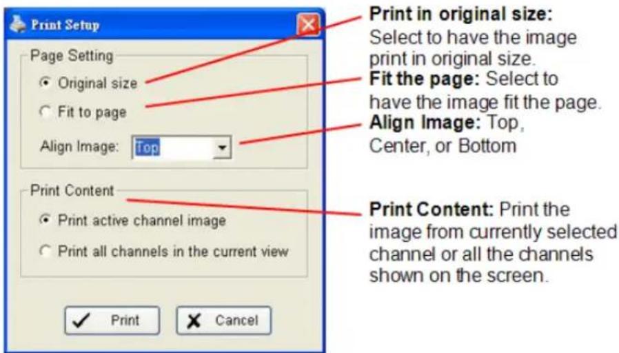
2.10 Backup
Different from Save Video, the Backup function saves everything from the Playback panel, including log information.
You can start a full function Playback Console and load the backup files into it on any PC with Windows operating system. This means you may monitor the real time video and work on the backup files on separate computers simultaneously.
Step 1: Press the "Open Record" to select data and press "Backup".
Step 2: You can adjust the Start Time and End Time you want to backup.
Step 3: You can adjust the Cameras you want to backup.
Step 4: You can calculate the size of the backup data.
IP Surveillance system
2. Playback

Step 5: Select the directory you want to save the backup data.
Step 6: Check the log you want to backup.
Step 7: Press the "Backup" to start backing up.
2. Playback
2.11 Log Viewer
2.11.1 Unusual Event: View the unusual event history that had been detected by the Smart Guard System.

Step1: Choose the type of events you wish to view or select "All" from the drop-down menu to view all types of events.
Step 2: Choose the camera channel you wish to view or select "All" for all the channels available.
Step 3: You can either view the events that happened on a particular date or during a given time period. To search and view unusual event on a particular date, check the option right next to “Date” and select a specific date.
You may also point out two different time points and search for unusual event happened during the period. Check the options in the Date &Time columns and enter the date and time.
Step 4: Click Search
Note: When working with a video record,
-
Log Viewer will search for Unusual Event in the video record in Date & Time mode, start from the beginning to the end of the record, which is the default setting of the system.
-
A link will appear right next to each event time. By clicking on the link, the video will jump to the point where the unusual event takes place.
IP Surveillance system
2. Playback
2.11.2 System Log: Select Log Type form the drop-down menu. There are total 11 types of log types, including:

- Main Console Startup 12. Stop Smart Guard
- Main Console Shutdown 13. Modify Smart Guard
- User Login 14. Modify Schedule
- User Login Failed 15. Modify Configuration
- Start Schedule 16. Start Live Streaming Server
- Stop Schedule 17. Stop Live Streaming Server
- Execute Recycle 18. Modify Live Streaming Server
- Execute Backup 19. Start Remote Playback Server
- Enable Channel 20. Stop Remote Playback Server
- Disable Channel 21. Modify Remote Playback Server
- Start Smart Guard 22. IP Camera Connection Lost
Step1: Choose the type of event you wish the check or select "All" from the drop-down menu and view all types of events.
Step 2: You can either view the events that happened on a particular date or during a given time period. To search and view unusual event on a particular date, check the option right next to “Date” and select a specific date.
You may also point out two different time points and search for unusual event happened during the period. Check the options in the Date &Time columns and enter the date and time.
Step 3: Click Search.
IP Surveillance system
3. Schedule
3. Schedule

Click on the Schedule icon on the Main Console and set up the time duration for video recording on the schedule configuration panel.
IP Surveillance system
3. Schedule
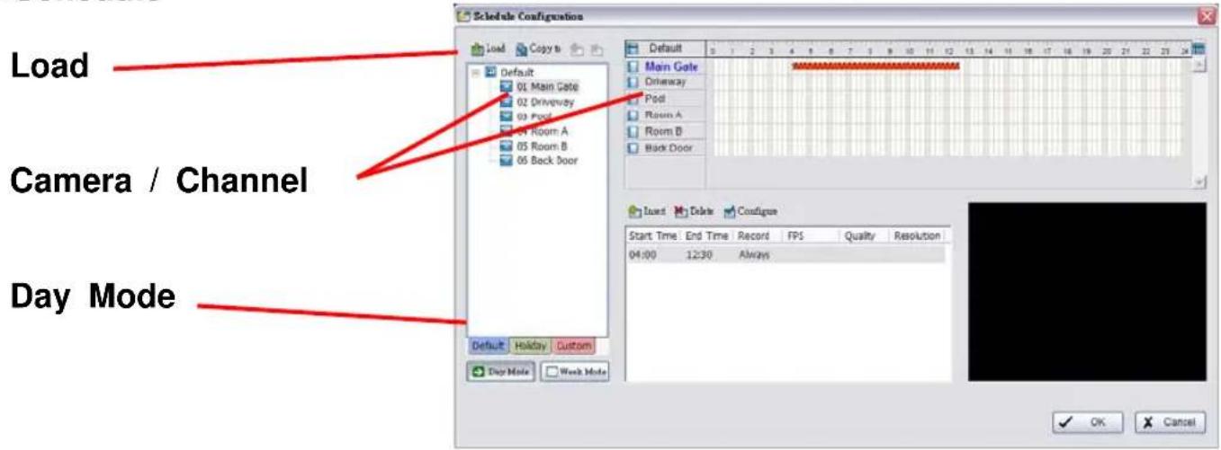
3.1 Day Mode
Schedule the cameras to turn the recorder on and off at the same time every day according to your setting.
To setup the time schedule for each camera, you may
-
Load the preset modes or
-
Insert a new schedule manually
3.2 Load Preset Modes
Click on the Load icon for the drop-down menu.
Regular Mode: Video recording 24 hours a day with the setting of 30 FPS (frames per second), Normal video quality and Normal resolution.
Office Mode: Video recording from 8 am to 8 pm (08:00 – 20:00, shown on the red bar in the Schedule Configuration panel) with 30 FPS, Normal video quality, and Normal resolution.
Shop Mode: Video recording from 10 am to 10 pm (10:00 – 22:00) with 30 FPS, Normal video quality, and Normal resolution.
High Security Mode: Video recording 24 hours a day with the setting of 30 FPS, the highest video quality, and High resolution.
Disk Saving Mode: The system will start recording only when a motion is detected on the screen, 24 hours a day (shown on the green bar in the Schedule Configuration panel), with the setting of 30 FPS, Normal quality, and Normal resolution. You can adjust the sensitivity, interval, and area of motion detection in the Schedule Configuration.
3. Schedule
Minor Mode: The system will start recording only when a motion is detected on the screen, 24 hours a day (shown on the green bar in the Schedule Configuration panel), with the setting of 15 FPS, Low quality, and Low resolution. You can adjust the sensitivity, interval and area of motion detection in the Schedule Configuration.
3.3 Insert a New Schedule Manually
Step 1: Left-click and draw the bar you want to the time table. The scheduled time will show as a grey bar.
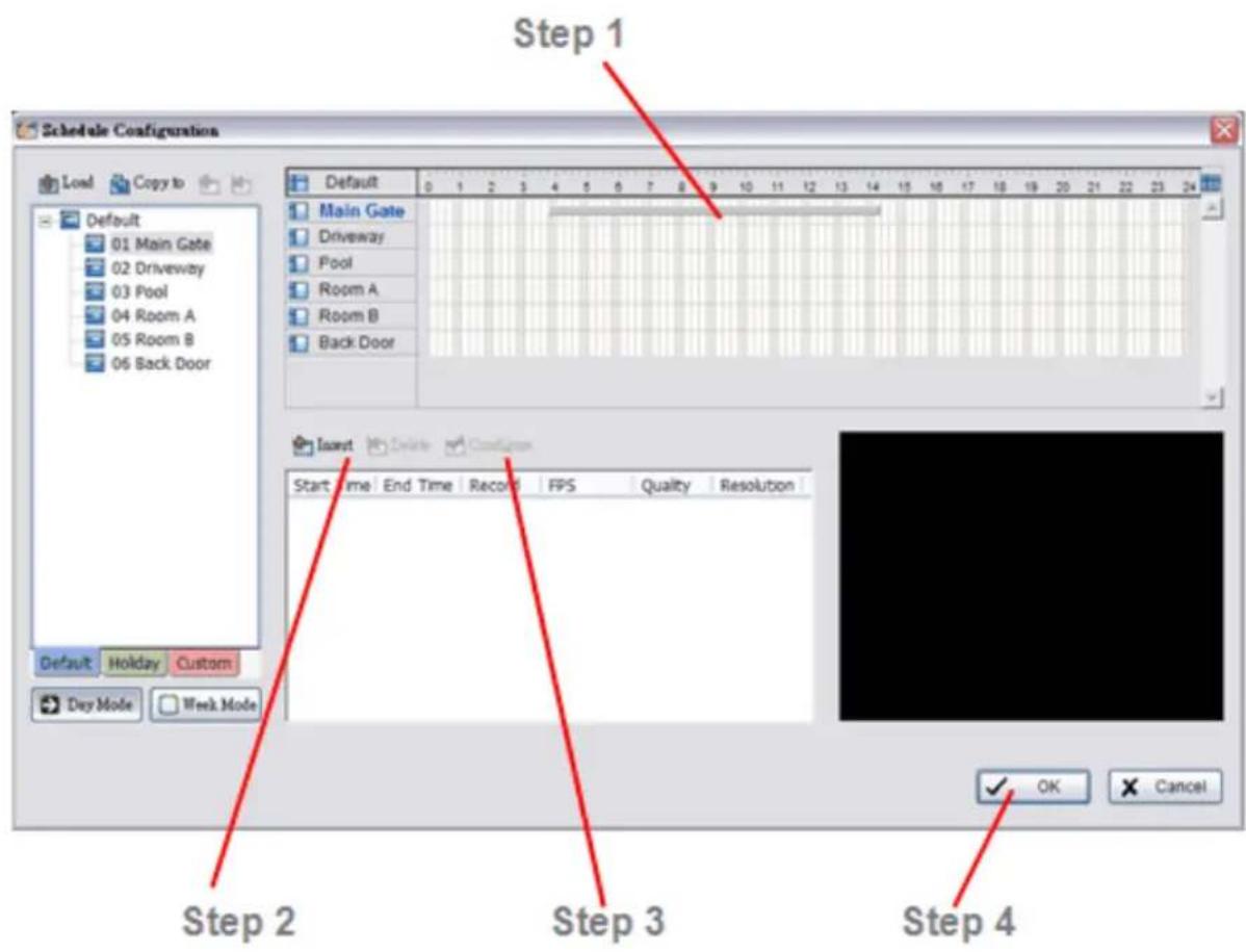
Step 2: Click the Insert icon and add a new schedule in the Regular Mode, i.e. to record video during the time period you set with 30 FPS, Normal video quality, and Normal resolution.
Step 3: Change the setting if wished by clicking on the Configure icon or double click the schedule information.
Step 4: Click OK.
IP Surveillance system
3. Schedule
3.4 Copy Schedule
You may set up the schedule for each channel/camera by repeating the process above, or simply apply the setting of a single camera to all the others.

3.5 Week Mode
Schedule the cameras for each day of the week differently. In addition, you may assign extra holidays under the Week Mode.

3.5.1 Default: Follow the same process to setup the schedule for every day in a week.
3.5.2 Holiday: You may assign holidays where the system will work according page-31
3. Schedule
to the setting of Sunday.
3.5.3 Custom: You can assign a particular date(s) on which the system will work according to a special schedule(s) different from the others.
3.6 Adjust the Scheduled Setting
You can manually change the setting at any time after you insert or load a period of schedule.
Option 1: Move the cursor to the Time Bar and change the length or move the bar sideway to change the start and end points.

Option 2: Click on the Configure icon or double click on schedule information on the screen (highlighted in blue) to obtain the Encoding Option panel and change the setting as wished.
Configure: Click on the configure icon to obtain the Encoding Option panel.
IP Surveillance system
3. Schedule
3.7 Encoding Option Panel

3.7.1 Always Record: Select this option to record the video at all time.
3.7.2 Record on Event (Unable in bundle version): Select this option to obtain the Select Event panel. From the Smart Guard list, check the box of the camera(s) that you want to trigger the recording action. Click OK to complete the setting.
3.7.3 Record on Motion: Select this option to start recording when there are motions detected. To detect Motion, you have to define a detection zone. Left-click and drag the mouse to draw a detection zone. You may define more than one zone on the screen by repeating the same process. User can also click on “All” button to select the entire detection zone. You may adjust the sensitivity and the frame interval.
3.7.4 Pre-record/ Post-record Time: The pre-record/ post-record function saves the recording data accordingly. For instance, to set up a 5 second pre-record time means the system will start saving the recording data 5 seconds before the event happens.
IP Surveillance system
4. Guard
4. Guard

Click on the Guard button on the Main Console to start the Event and Action Configuration panel. You need to specify an event to be detected as well as to set up an action with which the system will take when the specified event is detected.
IP Surveillance system
4. Guard

There are three sources of events: Camera (video image), Digital Input (device connected to you PC) and System (condition of your hardware). You can assign multiple events by following the instructions below.
4.1.1 Assign a Camera Event
Step 1: Select a channel from the camera list and click the insert event icon.

Step 2: Select the event you want on the Event Type list (for bundle version, only General Motion event is available), and then click OK.
Step 3: Configure the setting of the Event Type. See the following instructions.
4. Guard
4.1.2 Event - General Motion
Detect any movement in the defined detection zone.

Enable Event: Check the box to activate.
Life Cycle
Automatically cancel event when event disappears: the alarm/action will be off once the abnormality is fixed or ends.
Manually cancel event or event continues triggered: The alarm/action will continue until being canceled from the Main Console (Start>Open Event Report>Cancel All Events). The user currently not at the seat watching the screen will be notified by the alarm.
Activated Period: You can set up the system to react during a certain time period; for example, office hours
IP Surveillance system
4. Guard
Event - General Motion

Advanced setting
Sensitivity: Click and move the slider control to the right to increase sensitivity so that a relatively small movement will trigger the alarm. Move the bar to the left to reduce the sensitivity of movement detection. Set up an appropriate Sensitivity value will reduce the chance of false alarm. For example, you can lower the Sensitivity to avoid the alarm being triggered by a swinging tree in the breeze.
Interval: Click and move the slider control to the right to increase interval time so that the alarm will only be triggered when the movement lasts longer. Move to the left to reduce the interval time.
Region Definition: To detect General Motion, you have to define a detection zone. Left-click and drag the mouse to draw a detection zone. You may define more than one zone on the screen by repeating the same process. User can also click on "All" button to select the entire detection zone.
Start Simulation: Click the Start Simulation button and test the function on the preview screen.
4. Guard
4.2 Action
Insert Action: To setup actions responding to an unusual event.

Step 1: Choose an event and click the "Insert Action" icon.
Step 2: There are 6 types of actions: On Screen Display, Play Sound. Select the action you want on Action Type list and then click OK.
Step 3: Configure the setting of the Action Type if needed.
4.2.1 Action - Action Type
On Screen display: A red warning will be flashing on the screen of Main Console, indicating which type of unusual event is detected.
Play Sound: Sound alarm warning. Choose a Wave file (.wav) and the system will play the sound as alarm when an unusual event is detected.
6. Remote Live Viewer
5. Configuration

Modify the setting, log viewer, backup, and network services. Click on the Config icon, select from the drop-down menu and open the Configuration panel.
5. Configuration
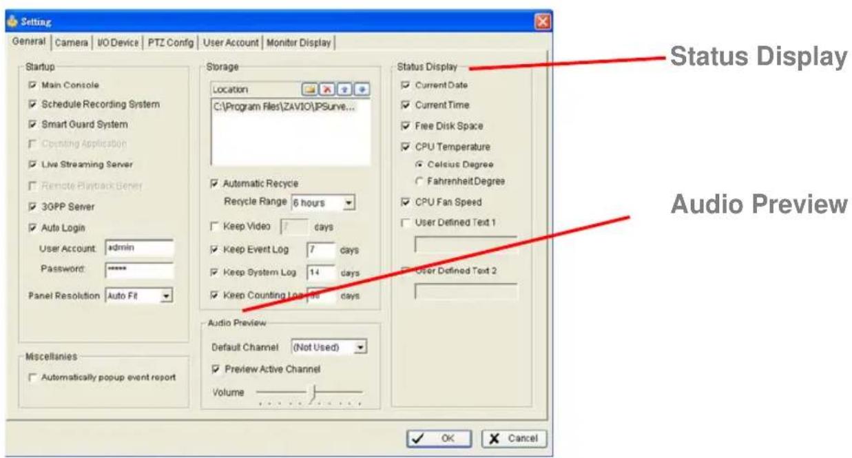
5.1 Setting – General
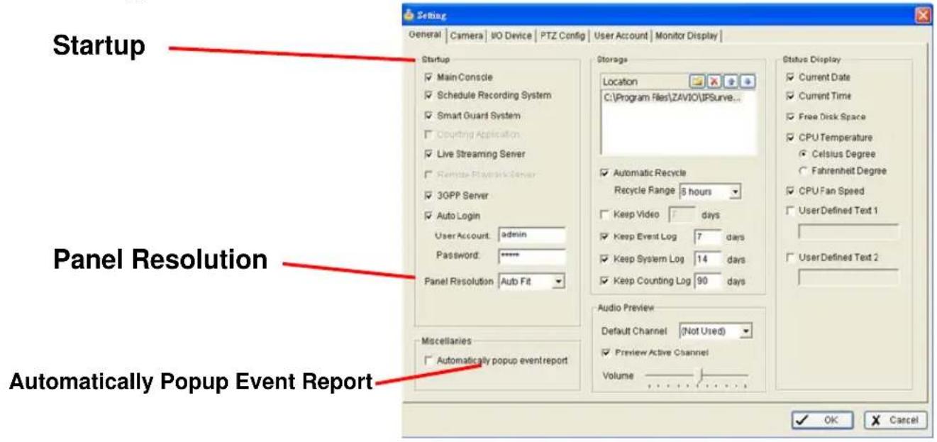
5.1.1 Startup
Check the box and activate the functions as the system starts. You may start/stop the function in Monitor panel on the Main Console.
Panel Resolution: Set up the resolution of the control panel. You may select Auto Fit to have the system choose the best one for you.
5.1.2 Automatically Popup Event Report: Event report dialog automatically popup when events been detected. Make sure to stop Smart Guard System before you modify the setting, otherwise the modification will not take place.

IP Surveillance system
5. Configuration
5.1.3 Storage
Location: Assign the default folder for the system to store all data files.
Automatic Recycle: The system will automatically delete out-dated data to save storage space.
Keep Video: Delete the video records that are older than the number of days set.
Keep Event Log: Delete the event log data that is older than the number of days set.
Keep System Log: Delete the system log data that is older than the number of days set.
Keep Counting Log: Delete the counting application data that is older than the number of days set.
5. Configuration
5.1.4 Audio Preview
Default Channel: Select the audio channel that you wish to hear from in "Default Channel.
Preview Active Channel: Check the “Preview Active Channel” option to hear the audio from selected video channel on Main Console. The default channel plays if the video channel isn’t selected.

System plays the audio of default channel
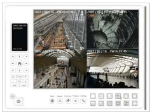
System plays the audio of left-top selected channel
Volume: Adjust the volume with the "volume bar."
IP Surveillance system
5. Configuration
5.1.5 Status Display
Check the boxes of the information that you wish to see in the information display window in the Main Console.

5. Configuration
5.2 Setting - Camera
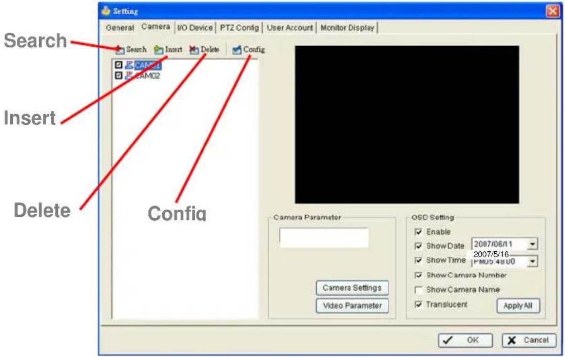
5.2.1 Add Camera
Four function buttons will be included in the Setting/Camera panel if you have our Hybrid Surveillance System license for IP camera.
Search: Click on the Search icon to obtain the Search IP Camera panel. The system will start scanning automatically once the panel is opened; feel free to stop scanning by clicking on the Stop Scan button.
Fill in the user name and password for each IP camera found and click OK to add it to the camera list.
Insert: Click on the Insert icon to obtain the IP/Video Server Setting panel and add IP cameras to the list.
Delete: Click on the delete button to remove the selected IP camera(s) from the system. Click OK to finalize the modification.

Config: Click on the Config button to obtain the IP/Video Server Setting panel. You can modify the IP camera settings with the Setting panel.
IP Surveillance system
5. Configuration
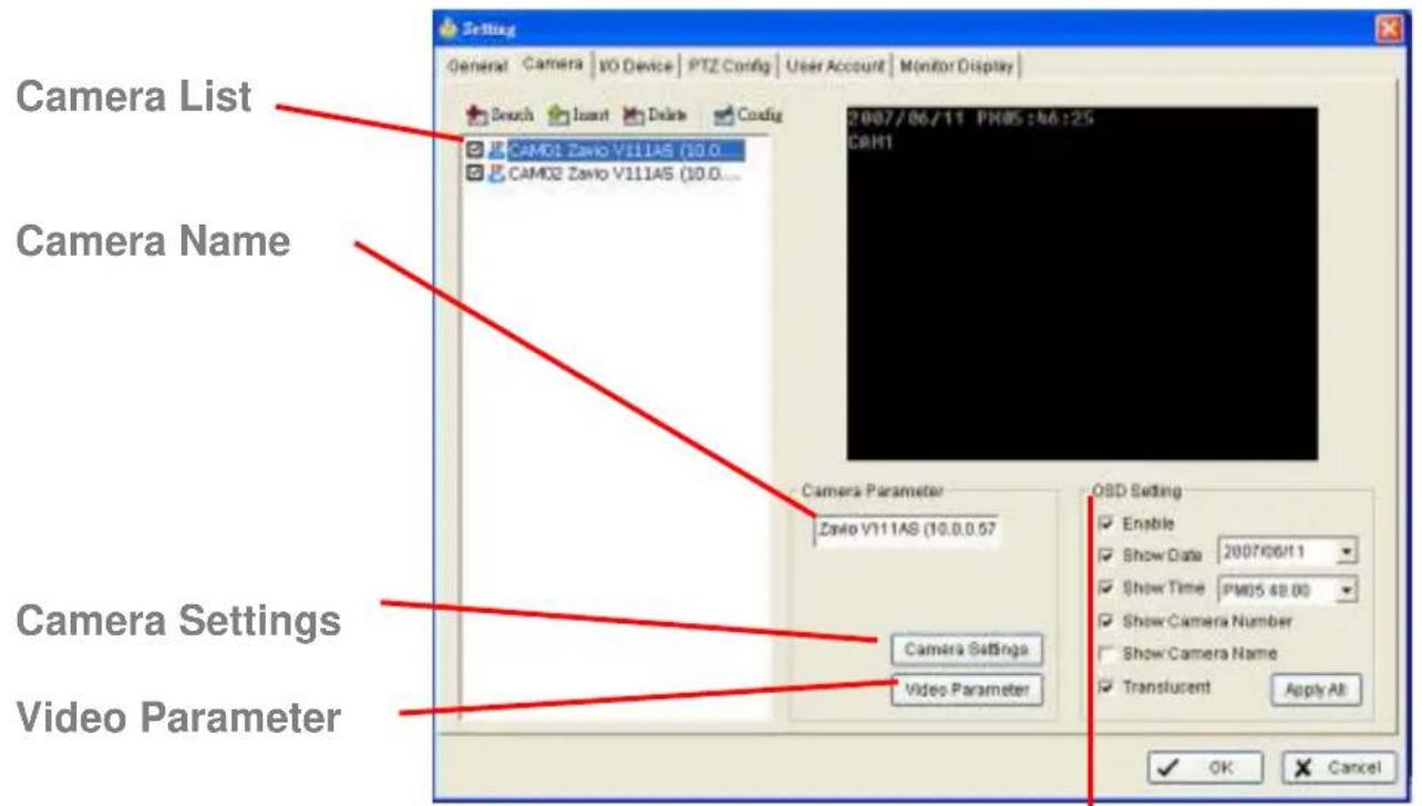
5.2.2 Camera Parameter
Camera List: The camera(s) connected to the system will show on the panel, click the name of the camera to adjust the setting.
OSD Setting
Camera Name: Name the camera for your convenience.
Camera Settings: Set the camera parameter offered by camera vendor.
Video Parameter: Adjusts the video's brightness, contrast, saturation, and color hue values.
5.2.3 OSD Setting: Select the information that you wish to see in the on-screen display, or the sub-screen of the camera.

5. Configuration
5.2.4 IP Camera / Video Server Setting Panel

Network: Fill up the Network field (including Name, IP Address, Http Port, User Name, Password and Protocol) referring to the instruction provided by the camera manufacturer. Check "Use DNS" to use domain name instead of IP address.
Device: Choose the IP camera manufacturer from the drop-down menu. Click on "Auto Detect" and the model name will show in the box.
Description: Show information of the IP camera.
IP Surveillance system
5. Configuration
5.3 Setting - I/O Device
Device Setting

Module Setting: Name the module device and ID that has been connecting the digital input/output device(s) to your system.
Device: This column displays the device(s) already installed to the system.
ID: Select the number of the I/O port to which you plug the ribbon cable.
Input Monitor: The device(s) is turned on if the dot is in red. By triggering the digital input device, the related icon will light up. This is used to check if the device is correctly connected or not.
Output Monitor: The device(s) is turned on if the dot is in red. By clicking on the icon, you may trigger the digital device connecting to the system. This can be used to test if the output device is correctly connected.
Device Setting
Name: Insert the name of the device (input and output).
Type: Select the device type from the drop-down menu.
N/O: Normal Open.
N/C: Normal Close.
5. Configuration
5.4 Setting - PTZ Config

Install PTZ cameras following the instruction of the camera manufacturers. A PTZ camera is usually connected to the PC with RS-485/RS-422.
Check the box on the camera list to activate the PTZ control function of a PTZ camera.
Basic Setting: Select the camera model, com port, baud rate, and address according to your PTZ camera.
Advanced Setting: You may setup the pan speed, tilt speed, zoom speed and auto pan speed. Adjust the settings by dragging the bars.
IP Surveillance system
5. Configuration
5.5 Setting - User Account

User Account: The administrator may manage the user accounts here. From the list on the right, highlight each account and modify the privilege setting.
5.6 Setting – Monitor Display
5. Configuration
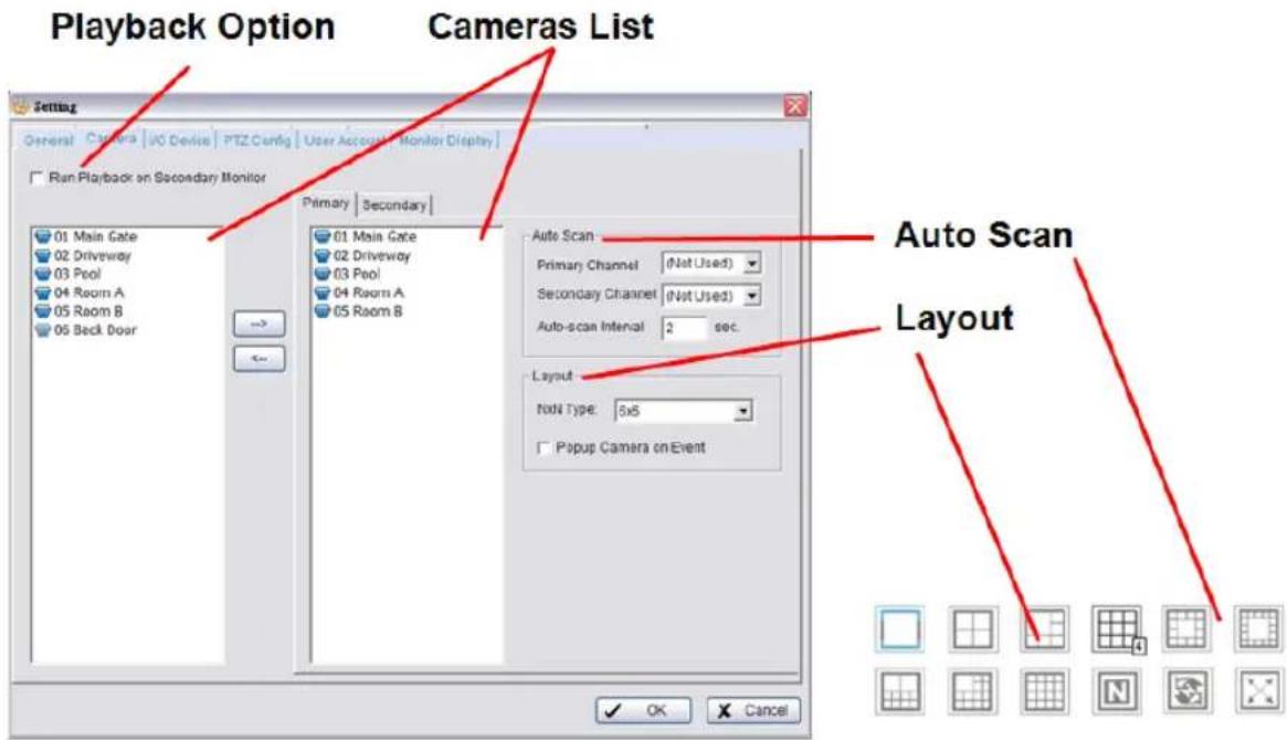
Playback Option: Execute Playback on the secondary monitor by checking the box. Make sure to adjust the display setting of your computer in advance to avoid system error. THE SECONDARY MONITOR OPTION IS NOT AVAILABLE.
Cameras List: The left side displays a list of all cameras; modify the cameras shown on the primary monitor in the right window.
Auto Scan: Activate auto scan to rotate the channels/ cameras on the display screen.
For instance, you may select to show only 4 sub-screens on the main console while having 16 channels connected to the system. With auto scan function, you will be able to see all 16 channels by turns.
Layout: Choose the number of divisions for NxN division on the Main Console screen.
5.7 Save/ Load Configuration
The Save/ Load Configuration function allows system users to save any specific setting as a cfg (config) file. You may save up several different cfg files at any time.
Save Configuration: To save a specific setting, go to Config > Save/ Load Configuration > Save. In the popup window, type in the file name and then save it as a cfg file.

Load Configuration: To load a specific setting, go to Config > Save/ Load Configuration > Load. In the popup window, go to the directory that you saved the cfg files at, select any one of them and then click OK to load the file. Main Console will be automatically shutdown after loading a new configuration. Please re-start Main Console manually.
Note: MainConsole will be automatically shutdown after loading a new configuration. Please re-start MainConsole manually.
IP Surveillance system
5. Configuration
5.8 Log Viewer
5.8.1 Log Viewer – Unusual Event

Unusual Event: View the history of unusual event that had been detected by the Smart Guard System.
Step1: Choose the type of event you want to check or select "All" from the drop-down menu for all types of events.
Step 2: Select the camera you want to check the event(s) from or select "All" for all available channels.
Step 3: You may view events happened on a particular date or during a given time period. To search and view unusual event happened on a particular date, mark the box right next to “Date” and indicate the date.
You may also point out two different time points and search for unusual events happened during the period. Mark the box in the Date&Time column and then enter the date and time.
Step 4: Click Search
5. Configuration
5.8.2 Log Viewer – System Log

Step 3
System Log: You can choose the log type from the drop-down menu, following is a complete list of all log types:
- Main Console Startup 12. Stop Smart Guard
- Main Console Shutdown 13. Modify Smart Guard
- User Login 14. Modify Schedule
- User Login Failed 15. Modify Configuration
- Start Schedule 16. Start Live Streaming Server
- Stop Schedule 17. Stop Live Streaming Server
- Execute Recycle 18. Modify Live Streaming Server
- Execute Backup 19. Start Remote Playback Server
- Enable Channel 20. Stop Remote Playback Server
- Disable Channel 21. Modify Remote Playback Server
- Start Smart Guard 22. IP Camera Connection Lost
Step1: Choose the type of event you want to check or select "All" from the drop-down menu for all types of events.
Step 2: You may view events happened on a particular date or during a given time period. To search and view unusual event happened on a particular date, mark the box right next to “Date” and indicate the date. You may also point out two different time points and search for unusual events happened during the period. Mark the box in the Date&Time column and then enter the date and time.
Step 3: Click Search.
IP Surveillance system
5. Configuration
5.9 Backup
5.9.1 Backup
The backup function saves video record and other log information. User may open backup files on any PC with Windows Operation System and operate the full function Playback panel on it. Follow the instructions below to obtain backup files.
Step 1: Click on "New Period" to obtain the Select DateTime Period panel.

Step 2: From the record date section, select the date you want to backup from. You will see color lines appear in the time table implying available data recorded. Red, green, and blue stands for record always, record on motion, and record on event data files, respectively.
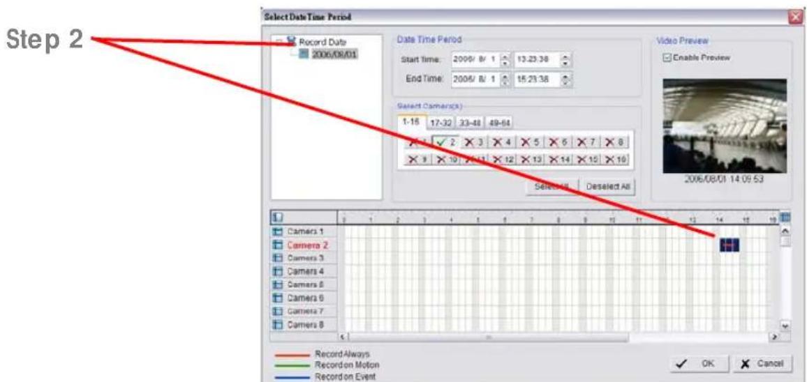
Step 3: Select the data you want to backup by highlighting the time period. Besides the time-table, you may also set up start time and end time in the Date Time Period section.
5. Configuration
Step 4: Click on the camera number icon to add camera(s) or click Select All to add all the cameras.
Step 5: Check the box of Enable Preview to get the preview of the video you select.
Step 6: Click OK when the settings are complete and go back to the Backup panel.


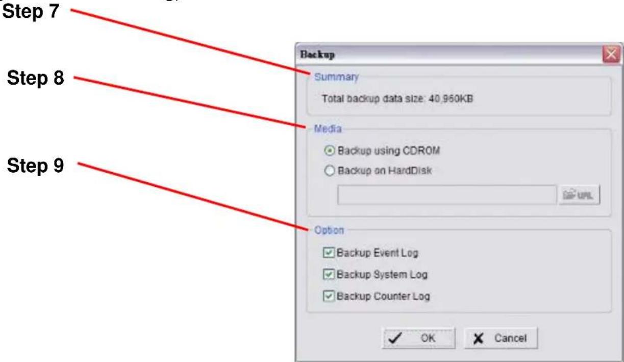
Step 7: Click the Backup icon to see the size of the file.
IP Surveillance system
5. Configuration
Step 8: Choose the path you want to save the file or burn the file into a CD (direct CD burning for Windows XP only).
Step 9: Select the log information you would like to backup (Event Log, System Log and/or Counter Log) and then click OK.
5.9.2 Delete Recorded Information from the System
Step 1: Click on "New Period" to obtain the Select Date Time Period panel.

Step 2: From the record date section, select the date you want to delete the file page-55
5. Configuration
from. You will see color lines appear in the time table implying available data. Red, green, and blue stands for record always, record on motion, and record on event data files, respectively.
Step 3: Select the data you want to delete by highlighting the time period. Besides the time-table, you may also set up start time and end time in the Date Time Period section.

Step 4: Click on the camera number icon to add camera(s) or click Select All to add all the cameras.
Step 5: Check the box of Enable Preview to get the preview of the video you select.
Step 6: Click OK when the settings are complete and go back to the Backup panel.

IP Surveillance system
5. Configuration
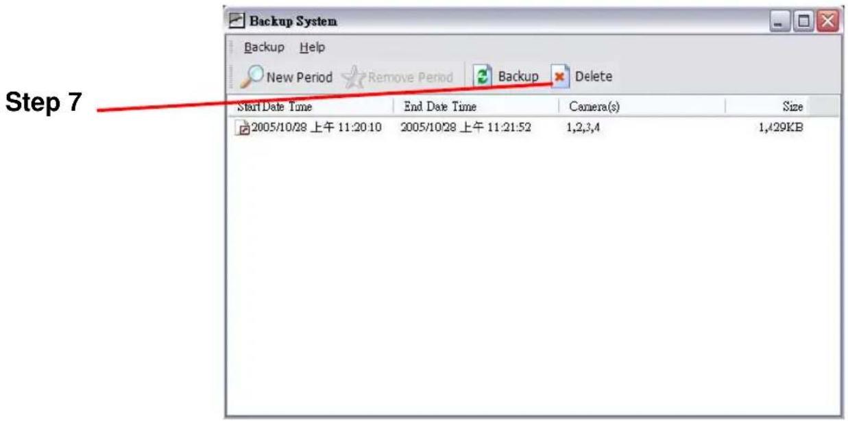
Step 7: Click on the "Delete" icon and delete the data.
Note: the deleted video cannot be recovered.
5. Configuration
5.10 Network Service
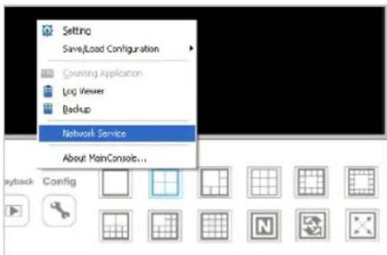
There are 5 types of network services: live streaming server, remote playback server, 3GPP service, Remote Desktop, and Central Management Service. From the Main Console, go to Config > Network Service to obtain the Network Service panel.
5.10.1 Live Streaming Server
When starting the live streaming function of your computer, you allow remote users to log on to the specific computer and view cameras that are connected to it. As system administrator, you are able to monitor these accounts in order to maintain the system efficiency.
Main
On Live Streaming Server panel, you can see the clients who are currently logging on to your computer and watching the live video from the remote side.

IP Surveillance system
5. Configuration
Start: By starting the system, you turn the computer into a live streaming server; thus allow remote users to log on to the system.
Kill Client: Highlight an IP address and click on the “Kill Client” button to block a client from your system.
Kill All Clients: By clicking on this button, you may block all the clients logging to your system.
Stop: Stop broadcasting live stream video.
Options: You may only adjust the setting when the server is stopped.
Port: Assign a port for the clients to connect to your system to the network.
Maximum Connections: Number of connections that are allowed to connect to your system. Default is 16 channels and maximum is 128, one camera video counts as one connection.
Use Default Web Server: Activate the Web server by checking the box; clients will be able to watch live video via Internet Explorer. The port for live streaming server is set to 80 by default. (*must check this item for system access via IE)
Save Log: Save the log information at appoint folder.
5. Configuration
Black/ White List

White List: Check the "Enable White List" box to activate the white list filter. Only IP from the white list is allowed to log in.
Black List: Check the "Enable Black List" box to activate the black list filter. IP from the black list will be blocked.
IP Address: Enter an IP address into the IP address field on the left. To add an IP address range to the system, enter 2 sets of IP address to indicate a series of IPs.
Add/Delete: To Add the IP(s) onto the list or remove it from the list.
Apply to All Playback Servers: To apply the setting to both live streaming server and remote playback server.
IP Surveillance system
5. Configuration
Performance
![Total bit rate Individual Camera bit rate Network Service - 10.0.0.21 Main Black/White List Performance Live Streaming Total bitrate: 0.0Kbps [2005/12/05 14:56:24] User Login: admin Accept [2005/12/05 14:56:24] Play CAM 1: admin [2005/12/05 14:56:29] Play CAM 2: admin [2005/12/05 14:56:31] Play CAM 5: admin [2005/12/05 14:56:33] Play CAM 9: admin [2005/12/05 14:56:36] Play CAM 12: admin [2005/12/05 14:56:38] Play CAM 14: admin ✓ OK Cancel](/content/2026/05/886437/images/f45016d37a87877ab4427eb583e01c5ba46ef07e674d1e50dce4c7bfbcc2111c.jpg)
Live Streaming Server log information
5. Configuration
5.10.2 Remote Playback Server
When starting the remote playback function of your computer, you allow remote users to log on to the specific computer and withdraw data files that are stored on it. As system administrator, you are able to monitor the accounts that log on in order to maintain the system efficiency.
Main
On Remote Playback Server panel, you can see the clients who are currently logging on to your computer and watching the live video from the remote side.
Start: By starting the system, you turn the computer into a remote playback server; thus allow remote users to access the system.
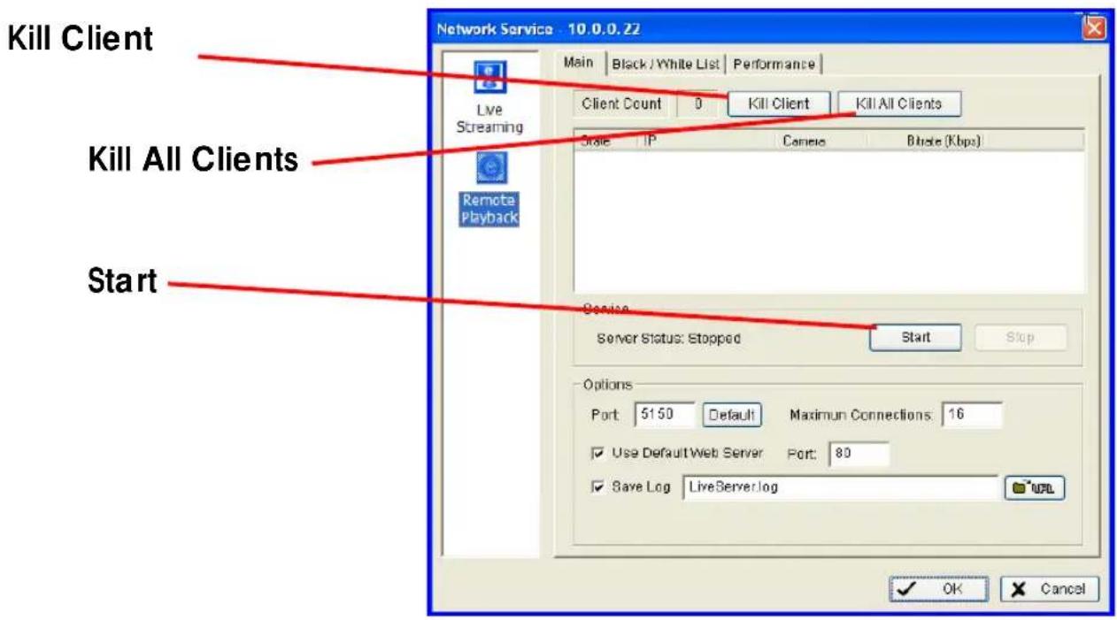
Kill Client: Highlight an IP address and click on the “Kill Client” button to block a client from your system.
Kill All Clients: By clicking on this button, you may block all the clients logging to your system.
IP Surveillance system
5. Configuration
Stop: Stop broadcasting playback video.

Options: You may only adjust the setting when the server is stopped.
Port: Assign a port for the remote playback server to connect to your system to the network.
Maximum Connections: Number of connections that are allowed to connect to the Remote Playback Server. Default is 8 accounts and maximum is 64, one account counts as one connection.
Save Log: Save the log information at appoint folder.
5. Configuration
Black/ White List

White List: Check the "Enable White List" box to activate the white list filter. Only IP from the white list is allowed to log in.
Black List: Check the "Enable Black List" box to activate the black list filter. IP from the black list will be blocked.
IP Address: Enter an IP address into the IP field on the left. To add an IP range to the system, enter 2 sets of IP to indicate a series of IPs.
Add/Delete: To Add the IP(s) onto the list or remove it from the list.
Apply to All Playback Servers: To apply the setting to both live streaming server and remote playback server.
IP Surveillance system
5. Configuration
Performance
Total bit rate
Individual Camera bit rate
![Network Service - 10.0.0.21 Main Black/White List Performance Live Streaming Remote Playback Total bitrate: 0.0Kbps [2005/12/05 14:56:24] User Login: admin Accept [2005/12/05 14:56:24] Play CAM 1: admin [2005/12/05 14:56:29] Play CAM 2: admin [2005/12/05 14:56:31] Play CAM 5: admin [2005/12/05 14:56:33] Play CAM 9: admin [2005/12/05 14:56:36] Play CAM 12: admin [2005/12/05 14:56:38] Play CAM 14: admin ✓ OK Cancel](/content/2026/05/886437/images/383fb6a3de20ccdee5a65c24228cf3712b91094aadbd6ec6fa935e01adb36041.jpg)
Live Streaming Server log information
5. Configuration
5.11 About Main Console
Go to About Main Console to view the version of your surveillance system and the hardware information.


6. Remote Live Viewer

With the Remote Live Viewer console, remote users may watch real-time video from remote live streaming servers.
6. Remote Live Viewer
6.1 Setup Panel

Click on the setup icon to obtain the setup panel
6.1.1 Setup Panel—Server
The Server Setting:
Step 1: Enter the Server Name which you want to use.
Step 2: enter the Address, Port, User Name, Password which you want to use to log in server.

Step 3: Enable the Save Password if you don't want enter the password again when login. Also can enable Auto Login option to auto login when start the Remote Live Viewer.
Step 4: Click on Test Server to check the server setting is available.
Step 5: Click add to insert the setting to server list.
6. Remote Live Viewer
Step 6: Select a server from right server list, change the setting on light panel and click update to modify setting. Or click Delete to remove the server form server list after selecting one server.
6.1.2 Setup Panel—Group
You may put different cameras into the same group
Step 1: Go to the Group tab of the LiveView Setting panel.
Step 2: Log in to all the servers that contain the camera(s) you would like to put into the group(s).
Step 3: Click "Insert" to create a new group; name the group for future reference.
Step 4: From the window at the right, highlight the camera(s) that you would like to add to a group and then click on the “<--” button. Repeat the process until you are satisfied with the group setting.
Step 5: Click on the Delete and Rename button to remove or rename a specific group.
Step 6: Repeat Step 3 to 5 until you are done with creating and setting groups.
Step 7: Click OK.
Step 1
Step 4
Step 2
Step 3
Step 5

6. Remote Live Viewer
6.1.3 Setup Cameras OSD
You may adjust font style on this panel,
Step 1: Enable camera OSD option.
Step 2: Select the font, font size, font color and any font effects desired.
Step 3: Select the information that you wish to see in the sub-screen of the camera.
6.1.3 Setup Remote Joystick Control

Please switch to Joystick tab and the configuration is the same as on Main console.
Note: The difference of Main Console is that the action of Goto camera option in Remote Live View is going to view of layout.
Following is a complete list of all log types.
6.2 Show Camera(s) On the Display Screen
Select a camera(s) from the server/ camera list on the right and then drag it to where you want the image to be displayed (limited to one camera at a time).
On the server/ camera list, right click on a camera to connect/ disconnect it.

natural_image
Street scene with a blue arrow pointing to a building, no visible text or symbols on the main image areaLog In/ Log Out: Select a server or a group and click on the log in/ out icon to access/ leave the server. You may also log in/ out from the server by right clicking on it.
Server and Camera List: Display a complete list of the server(s) and camera(s) that are added to the system.
PTZ Camera Control: You may control the camera view by utilizing the PTZ camera control panel to adjust the camera's view. This is only available with cameras that support PTZ function.
6. Remote Live Viewer
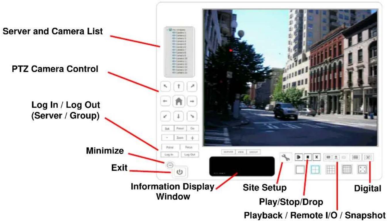
Minimize: Minimize the Remote Live View Console window.
Exit: Shut down the system or log out current user.
Digital Zoom: Click on the + and – signs to zoom in and out the view.
Play / Stop/ Drop: Select a camera/video and click on this button to play/stop/disconnect a particular channel.
Information Display Window: Display video information including server name, video current status, and bit rate for a selected channel.
Playback: View playback video remotely.
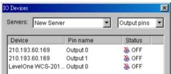
Remote I/O: User can remote adjust the Output Pins by turning it on or off (click on Status to turn △on or ▶off).
Snapshot: Select the snapshot function to capture a specific video image immediately.
7. Web View

Note: Must make sure the Liver Stream Server is enabled. Check 5.10 Network Service for more detail.
7.1 Server IP
Open an Internet Explorer browser and enter the IP address or DDNS "name" of the server followed by the connecting port.
Example: http://192.168.1.16:8080/
Note: 192.168.1.16 is the IP address of the server. 8080 is the port specified in "Use Default Web Server" in Network Service. ust make sure the Liver Stream Server is enabled. Check 5.10 Network Service for more detail. page-72
7. Web View
7.2 Remote Live Viewer
Press this icon to use Remote Live Viewer which functions are the same as Remote Live Viewer. You can only view one camera at a time!
7.3 Remote Playback
Press this icon to use Remote Playback which functions are the same as Playback but remote server and backup functions.
APPENDIX A – SYSTEM LOADING
Here are some testing results of multi-channel IP camera viewing:
1. 64 Channel IP Camera with CIF Performance
Equipment Configuration
| Software: | MainConsole Version 2.6.4 Professional |
| CPU: | Intel Core 2 Quad Q6600 @ 2400 MHz |
| Memory: | 1024 MB (2 x 512 DDR2-SDRAM) |
| Ethernet: | Marvell Yukon 88E8052 PCI-E ASF Gigabit Ethernet Controller |
| Hard Disk: | ST3250620A (250 GB) |
| Graphic card: | ATI Technologies Inc Radeon X1300 Series |
| Operating System: | Windows XP Professional SP2 |
Results from Test with a Resolution of 352 × 240
| 320x240 | Quality | Frame Rate | CPU Load | Bandwidth |
| 64 IP camera | Good 20 | 65% 40~50 Mbps | ||
| 64 IP camera | Excellent 20 | 67% 40~50 Mbps |
Appendix
2. 16 Channel IP Camera with D1 Performance
Equipment Configuration
| Software: | MainConsole Version 2.6.4 Professional |
| CPU: | AMD Athlon 64*2 @3600+MHz |
| Memory: | 2048 MB (2 x 1024 DDR2-SDRAM) |
| Ethernet: | VIA Rhine II Fast Ethernet Adapter |
| Hard Disk: | ST3250620A (250 GB) |
| Graphic card: | ATI Technologies Inc EAX1600 Series |
| Operating System: | Windows XP Professional SP2 x64 |
Results from Test with a Resolution of 704×480 CCD IP Camera
| 704x480 | Quality | Frame Rate | CPU Load | Bandwidth |
| 16 IP camera | Excellent 30 | 95% 15~20 | Mbps |
Results from Test with a Resolution of 640×480 CMOS IP Camera
| 640x480 | Quality | Frame Rate | CPU Load | Bandwidth |
| 16 IP camera | Excellent 30 | 95% 10~15 | Mbps |
Appendix
APPENDIX B - STORAGE REQUIREMENT TABLE (VGA)
Please refer to the following table to find out the capability for recording into your hard disk.
B.1. NTSC CCD IPCamera
B.1.1. MPEG4 Storage Requirement GB / channel / day @ 30fps
| Quality | 704*480 | 352*240 | 176*120 |
| Excellent | 21.1 | 8.4 | |
| Detailed | 9.0 | 2.6 | 0.8 |
| Good | 4.7 | 1.6 | 0.6 |
| Standard | 3.7 | 1.2 | 0.5 |
| Medium | 2.6 | 0.9 | 0.4 |
B.1.2. MPEG4 Storage Requirement GB / channel / day @ 15fps
| Quality | 704*480 | 352*240 | 176*120 |
| Excellent | 10.5 | 4.2 | |
| Detailed | 4.5 | 1.3 | 0.4 |
| Good | 2.3 | 0.8 | 0.3 |
| Standard | 1.8 | 0.6 | 0.2 |
| Medium | 1.3 | 0.5 | 0.2 |
B.1.3. MPEG4 Storage Requirement GB / channel / day
| Image-Size | Bitrate | Setting | Frame-Rate Setting | Storage Requirement |
| 704*480 | 2048 | 30 | 23.0 | |
| 704*480 | 2048 | 15 | 22.1 | |
| 704*480 | 1536 | 30 | 18.5 | |
| 704*480 | 1536 | 15 | 17.9 | |
| 704*480 | 1024 | 30 | 11.1 | |
| 704*480 | 1024 | 15 | 11.6 | |
| 704*480 | 512 | 30 | 5.5 | |
| 704*480 | 512 | 15 | 6.9 | |
| 352*240 | 1536 | 30 | 15.8 | |
| 352*240 | 1536 | 15 | 16.9 | |
| 352*240 | 1024 | 30 | 11.6 | |
| 352*240 | 1024 | 15 | 11.6 | |
| 352*240 | 512 | 30 | 5.6 | |
| 352*240 | 512 | 15 | 6.3 | |
| 176*120 | 1024 | 30 | 10.5 | |
| 176*120 | 1024 | 15 | 9.5 |
Appendix
| 176*120 | 512 | 30 | 5.6 |
| 176*120 | 512 | 15 | 5.8 |
| 176*120 | 128 | 30 | 1.6 |
| 176*120 | 128 | 15 | 1.6 |
B.1.4. MJPEG Storage Requirement GB / channel / day @ 15fps
| Quality | 704*480 | 352*240 | 176*120 |
| Excellent | 79.1 | 29.5 | 10.5 |
| Detailed | 52.7 | 15.8 | 7.4 |
| Good | 36.9 | 10.5 | 5.3 |
| Standard | 21.1 | 8.4 | 4.2 |
| Medium | 13.7 | 5.3 | 3.2 |
B.1.5. MJPEG Storage Requirement GB / channel / day
| Image-Size | Quality Setting | Frame-Rate Setting | Current Bitrate |
| 704*480 | Excellent | 15 | 79.1 |
| 704*480 | Excellent | 5 | 42.2 |
| 704*480 | Good | 15 | 36.9 |
| 704*480 | Good | 5 | 15.8 |
| 704*480 | Medium | 15 | 13.7 |
| 704*480 | Medium | 5 | 5.8 |
| 352*240 | Excellent | 15 | 29.5 |
| 352*240 | Excellent | 5 | 12.7 |
| 352*240 | Good | 15 | 10.5 |
| 352*240 | Good | 5 | 4.7 |
| 352*240 | Medium | 15 | 5.3 |
| 176*120 | Medium | 5 | 2.3 |
| 176*120 | Excellent | 15 | 10.5 |
| 176*120 | Excellent | 5 | 4.2 |
| 176*120 | Good | 15 | 5.3 |
| 176*120 | Good | 5 | 2.1 |
| 176*120 | Medium | 15 | 3.2 |
| 176*120 | Medium | 5 | 1.1 |
Appendix
B.2. PAL CCD IPCamera
B.2.1. MPEG4 Storage Requirement GB / channel / day @ 30fps
| Quality | 704*480 | 352*240 | 176*120 | |
| Excellent | 19.4 | 4.3 | 1.1 | |
| Detailed | 6.5 | 1.6 | 0.5 | |
| Good | 4.3 | 1.1 | 0.4 | |
| Standard | 3.2 | 0.9 | 0.3 | |
| Medium | 2.2 | 0.6 | 0.2 | |
B.2.2. MPEG4 Storage Requirement GB / channel / day @ 15fps
| Quality | 704*480 | 352*240 | 176*120 | |
| Excellent | 9.7 | 2.2 | 0.5 | |
| Detailed | 3.2 | 0.8 | 0.3 | |
| Good | 2.2 | 0.5 | 0.2 | |
| Standard | 1.6 | 0.4 | 0.2 | |
| Medium | 1.1 | 0.3 | 0.1 | |
B.2.3. MPEG4 Storage Requirement GB / channel / day
| Image-Size | Bitrate | Setting | Frame-Rate Setting | Storage Requirement |
| 704*480 | 2048 | 30 | 21.6 | |
| 704*480 | 2048 | 15 | 22.7 | |
| 704*480 | 1536 | 30 | 17.3 | |
| 704*480 | 1536 | 15 | 18.4 | |
| 704*480 | 1024 | 30 | 11.9 | |
| 704*480 | 1024 | 15 | 13.0 | |
| 704*480 | 512 | 30 | 5.9 | |
| 704*480 | 512 | 15 | 7.0 | |
| 352*240 | 1536 | 30 | 16.2 | |
| 352*240 | 1536 | 15 | 17.3 | |
| 352*240 | 1024 | 30 | 11.9 | |
| 352*240 | 1024 | 15 | 11.9 | |
| 352*240 | 512 | 30 | 5.9 | |
| 352*240 | 512 | 15 | 6.5 | |
| 176*120 | 1024 | 30 | 10.8 | |
| 176*120 | 1024 | 15 | 10.8 | |
| 176*120 | 512 | 30 | 5.9 | |
| 176*120 | 512 | 15 | 6.5 | |
| 176*120 | 128 | 30 | 1.6 | |
| 176*120 | 128 | 15 | 1.6 |
Appendix
B.2.4. MJPEG Storage Requirement GB / channel / day @ 15fps
| Quality | 704*480 | 352*240 | 176*120 | |
| Excellent | 84.2 | 18.4 | 7.0 | |
| Detailed | 46.4 | 10.8 | 4.9 | |
| Good | 27.0 | 7.0 | 3.8 | |
| Standard | 14.0 | 4.9 | 2.7 | |
| Medium | 10.8 | 3.2 | 1.9 | |
B.2.5. MJPEG Storage Requirement GB / channel / day
| Image-Size | Quality Setting | Frame-Rate Setting | Current Bitrate |
| 704*480 | Excellent | 15 | 84.2 |
| 704*480 | Excellent | 5 | 43.2 |
| 704*480 | Good | 15 | 27.0 |
| 704*480 | Good | 5 | 13.0 |
| 704*480 | Medium | 15 | 10.8 |
| 704*480 | Medium | 5 | 5.4 |
| 352*240 | Excellent | 15 | 18.4 |
| 352*240 | Excellent | 5 | 9.7 |
| 352*240 | Good | 15 | 7.0 |
| 352*240 | Good | 5 | 3.6 |
| 352*240 | Medium | 15 | 3.2 |
| 176*120 | Medium | 5 | 1.7 |
| 176*120 | Excellent | 15 | 7.0 |
| 176*120 | Excellent | 5 | 3.2 |
| 176*120 | Good | 15 | 3.8 |
| 176*120 | Good | 5 | 1.6 |
| 176*120 | Medium | 15 | 1.9 |
| 176*120 | Medium | 5 | 0.8 |
Appendix
B.3. CMOS IPCamera
B.3.1. MPEG4 Storage Requirement GB / channel / day @ 30fps
| Quality | 640*480 | 320*240 | 160*120 |
| Excellent | 10.5 | 3.2 | 0.9 |
| Detailed | 4.2 1.6 0.5 | ||
| Good | 3.2 1.1 0.3 | ||
| Standard | 2.6 0.7 0.3 | ||
| Medium | 2.6 0.6 0.2 |
B.3.2. MPEG4 Storage Requirement GB / channel / day @ 15fps
| Quality | 640*480 | 320*240 | 160*120 |
| Excellent | 5.3 1.6 0.4 | ||
| Detailed | 2.1 0.8 0.3 | ||
| Good | 1.6 0.6 0.2 | ||
| Standard | 1.3 0.4 0.1 | ||
| Medium | 1.3 0.3 0.1 |
B.3.3. MPEG4 Storage Requirement GB / channel / day
| Image-Size | Bitrate | Setting | Frame-Rate Setting | Current Bitrate |
| 640*480 | 2048 | 30 | 23.0 | |
| 640*480 | 2048 | 15 | 22.2 | |
| 640*480 | 1536 | 30 | 18.5 | |
| 640*480 | 1536 | 15 | 17.9 | |
| 640*480 | 1024 | 30 | 10.5 | |
| 640*480 | 1024 | 15 | 10.5 | |
| 640*480 | 512 | 30 | 5.3 | |
| 640*480 | 512 | 15 | 6.3 | |
| 320*240 | 1536 | 30 | 15.8 | |
| 320*240 | 1536 | 15 | 16.9 | |
| 320*240 | 1024 | 30 | 10.5 | |
| 320*240 | 1024 | 15 | 10.5 | |
| 320*240 | 512 | 30 | 5.8 | |
| 320*240 | 512 | 15 | 6.3 | |
| 160*120 | 1024 | 30 | 10.0 | |
| 160*120 | 1024 | 15 | 7.9 | |
| 160*120 | 512 | 30 | 5.3 | |
| 160*120 | 512 | 15 | 0.5 | |
| 160*120 | 128 | 30 | 1.4 | |
| 160*120 | 128 | 15 | 1.5 |
Appendix
B.3.4. MJPEG Storage Requirement GB / channel / day @ 15fps
| Quality | 640*480 | 320*240 | 160*120 |
| Excellent | 42.2 | 15.8 | 6.3 |
| Detailed | 25.3 | 9.5 | 4.2 |
| Good | 16.9 | 6.9 | 3.2 |
| Standard | 13.7 | 5.3 | 2.5 |
| Medium | 9.5 3.7 1.8 |
B.3.5. MJPEG Storage Requirement GB / channel / day
| Image-Size | Quality Setting | Frame-Rate Setting | Current Bitrate |
| 640*480 | Excellent | 15 | 42.2 |
| 640*480 | Excellent | 5 | 16.9 |
| 640*480 | Good | 15 | 16.9 |
| 640*480 | Good | 5 | 6.9 |
| 640*480 | Medium | 15 | 9.5 |
| 640*480 | Medium | 5 | 3.8 |
| 320*240 | Excellent | 15 | 15.8 |
| 320*240 | Excellent | 5 | 5.8 |
| 320*240 | Good | 15 | 6.9 |
| 320*240 | Good | 5 | 2.7 |
| 320*240 | Medium | 15 | 3.7 |
| 160*120 | Medium | 5 | 1.4 |
| 160*120 | Excellent | 15 | 6.3 |
| 160*120 | Excellent | 5 | 2.4 |
| 160*120 | Good | 15 | 3.2 |
| 160*120 | Good | 5 | 1.2 |
| 160*120 | Medium | 15 | 1.8 |
| 160*120 | Medium | 5 | 0.7 |
Appendix
APPENDIX C - STORAGE REQUIREMENT TABLE (MEGA)
Please refer to the following table to find out the capability for recording into your hard disk.
C.1.1. H.264 Storage Requirement GB / channel / day @ 15fps
| Quality | 1280*1024 | 1280*720 | 640*480 | 320*240 |
| Excellent | 232.4 | 157.7 | 24.9 | |
| Detailed | 141.4 | 107.9 | 16.6 | |
| Good | 107.9 | 74.7 | 14.2 | |
| Standard | 66.4 | 49.8 | 12.5 | 4.6 |
| Medium | 49.8 | 37.4 | 10.8 | 3.8 |
C.1.2. H.264 Storage Requirement GB / channel / day @ 10fps
| Quality | 1280*1024 | 1280*720 | 640*480 | 320*240 |
| Excellent | 157.7 | 116.2 | 20.8 | |
| Detailed | 99.6 | 74.7 | 15 | |
| Good | 74.7 | 54 13.3 4.7 | ||
| Standard | 54 | 37.4 | 10.8 | 4.2 |
| Medium | 37.4 | 29.1 | 10 |
C.1.3. MPEG4 Storage Requirement GB / channel / day
| Image-Size | Bitrate Setting | Frame-Rate Setting | Storage Requirement |
| 1280*1024 | 6144 | 15 | 522.9 |
| 1280*1024 | 6144 | 10 | 522.9 |
| 1280*1024 | 2048 | 15 | 182.6 |
| 1280*1024 | 2048 | 10 | 182.6 |
| 1280*1024 | 512 | 15 | 45.7 |
| 1280*1024 | 512 | 10 | 45.7 |
| 1280*720 | 6144 | 15 | 522.9 |
| 1280*720 | 6144 | 10 | 522.9 |
| 1280*720 | 2048 | 15 | 182.6 |
| 1280*720 | 2048 | 10 | 182.6 |
| 1280*720 | 512 | 15 | 45.7 |
| 1280*720 | 512 | 10 | 45.7 |
| 640*480 | 6144 | 15 | 522.9 |
| 640*480 | 6144 | 10 | 522.9 |
| 640*480 | 2048 | 15 | 182.6 |
| 640*480 | 2048 | 10 | 182.6 |
| 640*480 | 512 | 15 | 45.7 |
| 640*480 | 512 | 10 | 45.7 |
Appendix
| 320*240 | 6144 | 15 | 423.3 |
| 320*240 | 6144 | 10 | 298.8 |
| 320*240 2048 | 15 | 182.6 | |
| 320*240 | 2048 | 10 | 182.6 |
| 320*240 | 512 | 15 | 45.7 |
| 320*240 | 512 | 10 | 45.7 |
C.1.4. MPEG4 Storage Requirement GB / channel / day @ 15fps
| Quality | 1280*1024 | 1280*720 | 640*480 | 320*240 |
| Excellent | 315.4 | 249 | 49.8 | 10.8 |
| Detailed | 240.7 | 182.6 | 37.4 | |
| Good | 149.4 | 116.2 | 24.9 | |
| Standard | 99.6 | 74.7 | 20.8 | 5.9 |
| Medium | 74.7 49.8 | 16.6 5 |
C.1.5. MPEG4 Storage Requirement GB / channel / day @ 10fps
| Quality | 1280*1024 | 1280*720 | 640*480 | 320*240 |
| Excellent | 249 | 190.9 | 41.5 | 9.2 |
| Detailed | 182.6 | 132.8 | 33.2 | |
| Good | 116.2 | 91.3 | 20.8 | |
| Standard | 78.9 | 58.1 | 16.6 | 5.4 |
| Medium | 58.1 | 45.7 | 14.5 | 4.2 |
C.1.6. MPEG4 Storage Requirement GB / channel / day
| Image-Size | Quality Setting | Frame-Rate Setting | Storage Requirement |
| 1280*1024 | 6144 | 15 | 431.6 |
| 1280*1024 | 6144 | 10 | 522.9 |
| 1280*1024 | 2048 | 15 | 182.6 |
| 1280*1024 | 2048 | 10 | 182.6 |
| 1280*1024 | 512 | 15 | 45.7 |
| 1280*1024 | 512 | 10 | 45.7 |
| 1280*720 | 6144 | 15 | 522.9 |
| 1280*720 | 6144 | 10 | 522.9 |
| 1280*720 | 2048 | 15 | 182.6 |
| 1280*720 | 2048 | 10 | 182.6 |
| 1280*720 | 512 | 15 | 45.7 |
| 1280*720 | 512 | 10 | 45.7 |
| 640*480 | 6144 | 15 | 522.9 |
| 640*480 | 6144 | 10 | 522.9 |
| 640*480 | 2048 | 15 | 182.6 |
| 640*480 | 2048 | 10 | 182.6 |
Appendix
| 640*480 | 512 | 15 | 45.7 |
| 640*480 | 512 | 10 | 45.7 |
| 320*240 | 6144 | 15 | 182.6 |
| 320*240 | 6144 | 10 | 149.4 |
| 320*240 2048 | 15 | 182.6 | |
| 320*240 | 2048 | 10 | 149.4 |
| 320*240 | 512 | 15 | 45.7 |
| 320*240 | 512 | 10 | 45.7 |
Appendix
2.VGA Mode
C.2.1. H.264 Storage Requirement GB / channel / day @ 30fps
| Quality | 640*480 | 320*240 |
| Excellent | 66.4 | 10 |
| Detailed | 37.4 | 8.3 |
| Good | 24.9 | 5.9 |
| Standard | 16.6 | 5 |
| Medium | 15 | 4.2 |
C.2.2. H.264 Storage Requirement GB / channel / day @ 15fps
| Quality | 640*480 | 320*240 |
| Excellent | 41.5 | 8.3 |
| Detailed | 24.9 | 6.7 |
| Good | 20.8 | 5 |
| Standard | 15 | 4.6 |
| Medium | 12.5 | 4.2 |
C.2.3. H.264 Storage Requirement GB / channel / day
| Image-Size | Bitrate Setting | Frame-Rate Setting | Current Bitrate | Storage Requirement |
| 640*480 | 6144 | 30 | 6300 | 522.9 |
| 640*480 | 6144 | 15 | 6300 | 522.9 |
| 640*480 | 2048 | 30 | 2200 | 182.6 |
| 640*480 | 2048 | 15 | 2200 | 182.6 |
| 640*480 | 512 | 30 | 550 | 45.7 |
| 640*480 | 512 | 15 | 550 | 45.7 |
| 320*240 | 6144 | 30 | 6300 | 522.9 |
| 320*240 | 6144 | 15 | 5500 | 456.5 |
| 320*240 2048 | 30 | 2200 | 182.6 | |
| 320*240 | 2048 | 15 | 2200 | 182.6 |
| 320*240 | 512 | 30 | 550 | 45.7 |
| 320*240 | 512 | 15 | 550 | 45.7 |
C.2.4. MPEG4 Storage Requirement GB / channel / day @ 30fps
| Quality | 640*480 | 320*240 |
| Excellent | 116.2 | 20.8 |
| Detailed | 83 | 13.3 |
| Good | 49.8 | 10 |
| Standard | 33.2 | 7.5 |
| Medium | 24.9 | 6.7 |
Appendix
C.2.5. MPEG4 Storage Requirement GB / channel / day @ 15fps
| Quality | 640*480 | 320*240 |
| Excellent | 74.7 | 15 |
| Detailed | 54 | 11.7 |
| Good | 37.4 | 8.3 |
| Standard | 25 | 6.7 |
| Medium | 16.6 | 5.9 |
C.2.6. MJPEG Storage Requirement GB / channel / day
| Image-Size | Bitrate Setting | Frame-Rate Setting | Current Bitrate | Storage Requirement |
| 640*480 | 6144 | 30 | 6300 | 522.9 |
| 640*480 | 6144 | 15 | 6300 | 522.9 |
| 640*480 | 2048 | 30 | 2200 | 182.6 |
| 640*480 | 2048 | 15 | 2200 | 182.6 |
| 640*480 | 512 | 30 | 550 | 45.7 |
| 640*480 | 512 | 15 | 550 | 45.7 |
| 320*240 | 6144 | 30 | 5100 | 423.3 |
| 320*240 | 6144 | 15 | 2800 | 232.4 |
| 320*240 2048 | 30 | 2200 | 182.6 | |
| 320*240 | 2048 | 15 | 2200 | 182.6 |
| 320*240 | 512 | 30 | 550 | 45.7 |
| 320*240 | 512 | 15 | 550 | 45.7 |


- IP Surveillance System
- User's manual
- Table of Contents
- System Requirement
- Quick Start INSTALLATION
- Quick Start
- COMPLETE SETUP TYPE:
- ADD IP CAMERA(S)
- Set Schedule
- START RECORDING & SMART GUARD
- PLAYBACK
- Step 5:
- Step 6:
- Main Console
- Start
- Information Window:
- PTZ Camera Control:
- Preset/ Go:
- On Screen Menu
- Playback
- Information Window:
- Audio Volume Control:
- Screen Division:
- Browse Mode:
- Date Time:
- Date Time Panel Withdraw the records:
- Enhancement
- Filter Setting
- Save Video
- Save Image
- Backup
- Log Viewer
- Schedule
- Day Mode
- Load Preset Modes
- Insert a New Schedule Manually
- Copy Schedule
- Week Mode
- Adjust the Scheduled Setting
- Encoding Option Panel
- Guard
- Assign a Camera Event
- Event - General Motion
- Life Cycle
- Event - General Motion
- Advanced setting
- Action
- Action - Action Type
- Remote Live Viewer
- Configuration
- Setting – General
- Startup
- Storage
- Audio Preview
- Status Display
- Setting - Camera
- Add Camera
- Camera Parameter
- IP Camera / Video Server Setting Panel
- Setting - I/O Device
- Device Setting
- Setting - PTZ Config
- Setting - User Account
- Setting – Monitor Display
- Save/ Load Configuration
- Log Viewer
- Log Viewer – Unusual Event
- Log Viewer – System Log
- Backup
- Backup
- Delete Recorded Information from the System
- Network Service
- Live Streaming Server
- Main
- Black/ White List
- Performance
- Remote Playback Server
- About Main Console
- Setup Panel
- Setup Panel—Server
- Setup Panel—Group
- Step 1
- Step 4
- Step 2
- Step 3
- Step 5
- Setup Cameras OSD
- Setup Remote Joystick Control
- Show Camera(s) On the Display Screen
- Web View
- Server IP
- Remote Live Viewer
- Remote Playback
- APPENDIX A – SYSTEM LOADING
- 64 Channel IP Camera with CIF Performance
- Appendix
- 16 Channel IP Camera with D1 Performance
- APPENDIX B - STORAGE REQUIREMENT TABLE (VGA)
- B.1. NTSC CCD IPCamera
- B.2. PAL CCD IPCamera
- B.3. CMOS IPCamera
- APPENDIX C - STORAGE REQUIREMENT TABLE (MEGA)
- 2.VGA Mode
Brand : Intellinet
Model : NFC30-IRWG
Category : Surveillance Camera