
Wireless Network IP Camera 550703 - Surveillance Camera Intellinet - Free user manual and instructions
Find the device manual for free Wireless Network IP Camera 550703 Intellinet in PDF.


| Product Type | Wireless Network IP Camera |
| Model | 550703 |
| Brand | Intellinet |
| Dimensions (LxWxH) | 110 x 60 x 50 mm |
| Weight | 300 g |
| Power Supply | DC 12V / 1A |
| Image Sensor | 1/4" CMOS, 1.3 Megapixel |
| Resolution | 1280 x 720 (720p) |
| Lens | Fixed, 3.6 mm |
| Night Vision | IR LEDs, up to 20 m |
| Wireless Connectivity | Wi-Fi 802.11 b/g/n |
| Motion Detection | Yes |
| Two-Way Audio | Built-in microphone and speaker |
| Storage | MicroSD card slot (up to 32GB) |
| Mounting | Wall or ceiling |
| Operating Temperature | -10°C to 50°C |
| Wireless Security | WEP, WPA, WPA2 |
| Maintenance | Clean lens with soft, dry cloth |
| Spare Parts | Power adapter, mounting screws, antenna |
| Repairability | Not user-serviceable; contact support |
Frequently Asked Questions - Wireless Network IP Camera 550703 Intellinet
User questions about Wireless Network IP Camera 550703 Intellinet
0 question about this device. Answer the ones you know or ask your own.
Ask a new question about this device
Download the instructions for your Surveillance Camera in PDF format for free! Find your manual Wireless Network IP Camera 550703 - Intellinet and take your electronic device back in hand. On this page are published all the documents necessary for the use of your device. Wireless Network IP Camera 550703 by Intellinet.
USER MANUAL Wireless Network IP Camera 550703 Intellinet
Wireless Network IP Camera
PROFESSIONAL SERIES
Model 550703
User's Guide LV2.0
WIRELESS NETWORK IP CAMERA User's Guide
FCC Compliance Statement
The users manual or instruction manual for an intentional or unintentional radiator shall caution the user that changes or modifications not expressly approved by the party responsible for compliance could void the user's authority to operate the equipment.
NOTE: This equipment has been tested and found to comply with the limits for a Class B Digital Device, pursuant to Part 15 of the FCC Rules. These limits are designed to provide reasonable protection against harmful interference in a residential installation. This equipment generates, uses and can radiate radio frequency energy and, if not installed and used in accordance with the instruction, may cause harmful interference to radio communication. However, there is no guarantee that interference will not occur in a particular installation if this equipment does cause harmful interference to radio or television reception, which can be determined by turning the equipment off and on. The user is encouraged to try to correct the interference by one or more of the following measures:
- Reorient or relocate the receiving antenna.
- Increase the separation between the equipment and receiver
- Connect the equipment into an outlet on a circuit different from that to which the receiver is connected.
- Consult the dealer or an experienced radio/TV technician for help.

Wireless Network
IP Camera User's Guide
Copyright January 2005
WIRELESS NETWORK IP CAMERA User's Guide
Important Notice
- Camera surveillance laws may differ for each country. Please contact the local authorities to avoid any surveillance law violations.
- Please note that the CMOS lens that comes with the Wireless Network IP Camera can be damaged permanently if the camera lens is exposed to direct sunlight. If your application demands prolonged exposure to sunlight, you should consider equipping it with a sun visor.
- The Wireless Network IP Camera is not weatherproof. Please be aware of environmental specifications included in the manual. For outdoor use, please use a weatherproof case to protect the Wireless Network IP Camera from water, moisture, or temperature (higher or lower than specification). For Wireless Network IP Camera cleaning, gently wipe with clean dry cloth.
- Be sure to use only the DC adapter that is provided with your camera. Connecting the Wireless Network IP Camera directly to AC current may cause electric damages to the Camera.
- Be cautious when handling Wireless Network IP Camera. Physical shocks may cause serious damage.
- Be sure to mount the Wireless Network IP Camera securely to avoid any human injuries. Please keep the Wireless Network IP Camera out of reach of children.
- If the Wireless Network IP Camera does not operate properly, please contact the closest local Wireless Network IP Camera distributor for after sales service. In all cases, you are prohibited from disassembling the product. If you do, INTELLINET ACTIVE NETWORKING is not responsible for any malfunction or the service warranty.
WIRELESS NETWORK IP CAMERA User's Guide
TABLE OF CONTENTS
PRODUCT OVERVIEW 5
ABOUT WIRELESS IP NETWORK CAMERA 5
MAIN FEATURES AND BENEFITS 6
SYSTEM REQUIREMENTS 8
PHYSICAL DESCRIPTION 9
CONTENTS 9
TOP VIEW AND DESCRIPTION 10
REAR VIEW AND DESCRIPTION 11
INSTALLATIONSUMMARY 12
ASSIGNING IPADDRESS & ACCESSING NETWORK IP CAMERA HOME PAGE 13
ASSIGNING IP ADDRESS 13
ASSIGNING IP ADDRESS BY USING IP INSTALLER 14
CONNECTING WIRELESS NETWORK IP CAMERA TO A PC 14
USING IP INSTALLER 15
ASSIGNING IP ADDRESS BY USING HYPER TERMINAL 17
CONFIGURING HYPER TERMINAL 17
ASSIGNING AN IP ADDRESS 19
ACCESSING THE WIRELESS NETWORK IP CAMERA HOME PAGE 22
STARTING THE WEB BROWSER 22
LOGIN PAGE 22
NETWORK IP CAMERA HOME PAGE 26
ADJUSTING THE CAMERA LENS 29
ADJUSTING THE FOCUS 29
REPLACING THE LENS 30
WIRELESS NETWORK IP CAMERA User's Guide
CONFIGURING ADMINISTRATION TOOLS 31
ADMINISTRATOR MENU OVERVIEW 32
IMAGE CONFIGURATION 33
NETWORK CONFIGURATION 35
IP CONSTRUCTION AND NETWORK CLASS 57
C CLASS NETWORK 58
E. UPDATING FIRMWARE 61
IDENTIFY THE VERSION OF FIRMWARE 61
DOWNLOAD NEW FIRMWARE 61
INSTALL NEW FIRMWARE 62
F. THE I/O CONNECTOR 63
G.RS 232 CABLE 64
H. DYNAMIC DOMAIN NAME SERVER 65
I. HIGH-SPEED SOLUTIONS 72
J. REINSTATING THE FACTORY DEFAULT SETTINGS 74
K. GLOSSARY OF TERMS 75
WIRELESS NETWORK IP CAMERA User's Guide
PRODUCT OVERVIEW

natural_image
Exterior view of a silver wireless router with two black antennas and a central lens (no visible text or symbols)About the Wireless Network IP Camera
The Wireless Network IP Camera can be connected directly to Ethernet or Fast Ethernet networks and also supports wireless transmission based on the IEEE 802.11b standard. It is different from the conventional PC Web Camera; the Wireless Network IP Camera is as standalone system with built-in CPU and web-based solutions providing a low cost product that can transmit high quality video images for monitoring. The wireless Network IP Camera can be managed remotely, accessed and controlled by any PC/Notebook over an intranet or the Internet via a web browser. The simple installation procedures and web-based interface allows easy integration into your network application environments coupled with many applications such as remote monitoring for a cost-effective solution.
WIRELESS NETWORK IP CAMERA User's Guide
Main Features and Benefits
Convenient Operation
The Wireless Network IP Camera is a standalone system with built-in CPU requiring no special hardware or software such as PC frame grabber cards. The Wireless Network IP Camera supports both Active-X mode for Internet Explorer and JAVA mode for Internet Explorer and Netscape Navigator. Therefore, all that is required is a common web browser, such as Microsoft Internet Explorer 4.x or above.
Open Standards
The Wireless Network IP Camera supports TCP/IP networking, SMTP e-mail, HTTP and other Internet-related protocols. It can be used in a mixed operating system environment with Windows, Unix, Mac and OS/2. It integrates easily into other web/intranet applications and CGI scripts.
Wired and Wireless Network Support
The Wireless Network IP Camera supports both wired and wireless transmission providing the advantage of mobility, flexibility and high-speed wireless LAN based technology (IEEE 802.11b) to transform it into a total solution for your network. Three modes can be configured from the slide on the rear panel:
- Local Area Network (Ethernet / Fast Ethernet) only
- Local Area Network (Ethernet / Fast Ethernet) and Wireless Local Area Network (802.11b)
• Wireless Local Area Network (802.11b) only
Simple Administration
Using a standard web browser, you can configure and manage the Wireless Network IP Camera directly from its own embedded web pages. The embedded operating system is upgradeable through the network.
Firmware Upgrades are available on the web at: http://www.intellinet-network.com/ipcamera/
External Devices
The auxiliary input/output connector on the camera allows you to connect your Wireless Network IP Camera to a variety of external devices; such as IR-sensors, switches, and alarm relays.
WIRELESS NETWORK IP CAMERA User's Guide
Security
Your Wireless Network IP Camera includes a self-contained web server, which means that digital images can be secured in the same manner as with any other Internet host. Your Network Administrator, using the unit's security settings in combination with an organization's Internet firewall, normally implements data protection. The Administrator can decide whether individuals, groups, or the whole world may access the camera. The Wireless Network IP Camera supports multi-user password protection
Compression and Performance
With an adaptive frame rate dependent on the image and lighting conditions, the Wireless Network IP Camera delivers up to 30 JPEG images per second at a resolution of 320x240.
Broad Range of Applications
With today's high-speed Internet services, the Wireless Network IP Camera can provide the ideal solution for live video images over the intranet and Internet for remote monitoring. The Wireless Network IP Camera allows remote access from a web browser for live image viewing and allows Administrator to manage and control the Wireless Network IP Camera anywhere and any time. Apply the Wireless Network IP Camera to monitor various objects and places such as homes,, offices, banks, hospitals, child-care centers, amusement parks and other industrial and public facilities. The Wireless Network IP Camera can also be used for intruder detection, to capture still images for archiving and many more applications.
Free Application Software \*
IP Installer – for quick installation
Multi-Viewer - for viewing of 4 cameras simultaneously
PDA Viewer – for viewing the camera on Windows CE PDA devices.
* Available at http://www.intellinet-network.com/ipcamera/.
WIRELESS NETWORK IP CAMERA User's Guide
System Requirements
Network
10Base-T Ethernet or 100Base TX Fast Ethernet
Wireless Local Area Network
IEEE 802.11b Wireless LAN
Recommended PC or Notebook to Access the Wireless Network IP Camera.
System Requirements:
CPU: Pentium II, 266 MHz or above
Memory Size: 32 MB (64MB recommended)
VGA card resolution: 800 x 600 or above
Web Browser:
Internet Explore 5.0 or above (Active-X & JAVA Mode-Image View for Windows OS and JAVA Mode – Image View for other OS)
Netscape 6.0 or above (JAVA Mode - Image View)
Multi-View Applications:
Supports OS: Win 98, Win 98 SE, Win 2000, Win Me, Win XP
System requirements for Multi-View:
CPU: Pentium III, 450 MHz or above
Memory Size: 128 MB (256 MB Recommended)
VGA card resolution: 800x600 or above
WIRELESS NETWORK IP CAMERA User's Guide
PHYSICAL DESCRIPTION
Contents
Carefully remove all items from the package. In addition to this User's Guide, be certain that you have:
◆ One Wireless Network IP Camera (550703)
◆ Two External Wireless Antennas
◆ One Installation CD-ROM
◆ One Quick Installation Guide
One Printed Manual
One AC Power Adapter (suitable for your country's electric power)
One Camera Stand
* If any item is missing, or if you find any damage or mismatch, promptly contact your dealer for assistance.
WIRELESS NETWORK IP CAMERA User's Guide
Top view and Description

Image Capture LED (red): The Image Capture LED flashes when users are accessing the camera,. It flashes once when an image is being captured or saved.
Operating Status LED (green): This LED indicates the Wireless Network IP Camera's operating status. Once power is supplied, the LED stays on for the first 15-20 seconds, and then it blinks once every second as long as the power is connected properly.
Network Activity LED (green): This LED indicates network activity.
NOTE
- After connecting the Ethernet network, the status led (green) on the right side of the camera should be on. If not, check your network connection.
- The slide switch on the rear panel must be positioned to LAN/WAN or WLAN setting for the wireless communication to take effect.
WIRELESS NETWORK IP CAMERA User's Guide
Rear View and Description
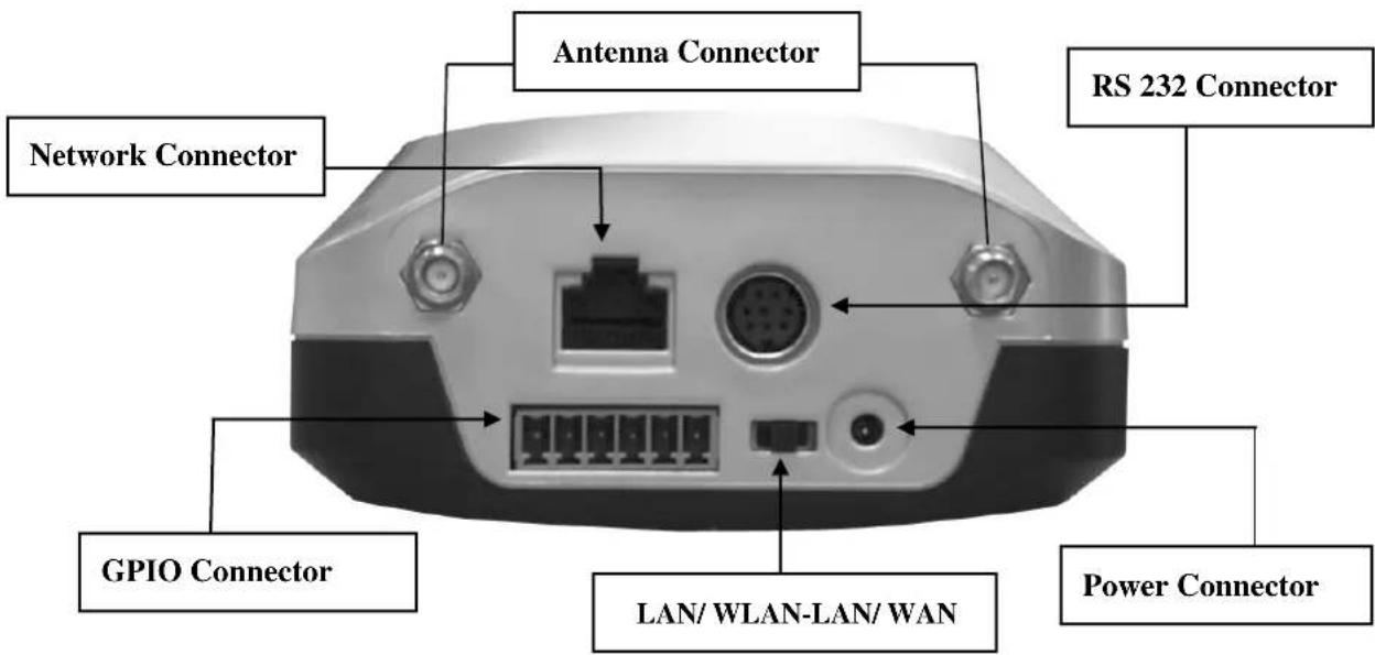
Power Connector: Only use the AC adapter provided by your dealer to avoid any possible damage from electric shock.
Network Connector: For connection of 10baseT Ethernet or 100base TX Fast Ethernet cable.
GPIO Connector: For connection of external devices such as infrared sensors, alarms, or motion detectors (please refer to Appendix F – The I/O Connector).
RS232 Cable Connector: For connection of external devices such as an external pan/tilt/zoom mechanism, or direct connection to a serial port for configuration (please refer to Appendix G - RS 232 Cable).
IMPORTANT
-
After connecting the Ethernet network, the status led (green) on the right side of the camera should be on. If not, check your network connection.
-
Connect Wireless Network IP Camera to Ethernet network. The default position of the camera's network switch is in the center position, meaning the camera operates in both LAN and WLAN modes.
WIRELESS NETWORK IP CAMERA User's Guide
INSTALLATION SUMMARY
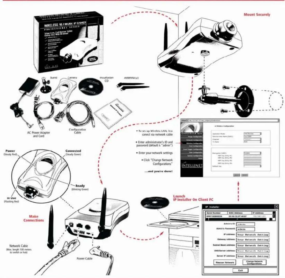
- Connect Ethernet and power to the Wireless Network IP Camera.
- Install and launch the "IP-Installer"
- Assign an IP address and network settings
- Securely mount the Wireless Network IP Camera.
- Adjust the Focus
WIRELESS NETWORK IP CAMERA Quick & Easy Setup
flowchart
graph TD
A["Wireless Network IP CABO"] --> B["Mount Securely"]
B --> C["AC Power Adapter and Cord"]
B --> D["Configurations Cable"]
B --> E["Connected (Steady Green)"]
B --> F["Ready (Blinking Green)"]
B --> G["Network Cable (Max. length 100 meters to switch or full)"]
B --> H["Power Cable"]
C --> I["To set up Wireless LAN, first connect via network cable"]
D --> J["Enter administrator's ID and password (default is "admin")"]
D --> K["Enter your network settings"]
D --> L["Click "Change Network Configurations"<br>...and you're done!"]
E --> M["Launch IP Installer On Client PC"]
F --> M
G --> M
H --> M
I --> N["IP Installer"]
J --> N
K --> N
L --> N
M --> O["Signal Number MAC Address IP Address"]
O --> P["Active ID: Admin"]
O --> Q["Admin's Password: admin"]
O --> R["IP Address: Your Network Setting"]
O --> S["Gateway Address: Your Network Setting"]
O --> T["Submit Mask Address: Your Network Setting"]
O --> U["CNS/Server Address: Your Network Setting"]
O --> V["Server IP Address: Your Network Setting"]
O --> W["Rescan Network Change Network Configurations"]
W --> X["Exit"]

www.intellinet-network.com
All names of products or services mentioned herein are trademarks or registered trademarks of their respective owners. Distribution and reproduction of this document, use and disclosure of the contents herein are prohibited, unless specifically authorized.
Copyright © INTELLINE? ACTIVE NETWORKING ^1
WIRELESS NETWORK IP CAMERA User's Guide
ASSIGNING IP ADDRESS & ACCESSING THE WIRELESS NETWORK IP CAMERA HOME PAGE
Assigning an IP Address
To access the Wireless Network IP Camera, you need to assign an appropriate network IP address.
IMPORTANT
- Please use the newly assigned IP address, do NOT use any occupied IP address, the default, or the example IP address.
- It is highly recommended that you assign an IP address before placing the Wireless Network IP Camera in a remote location or network.
• Network IP Address:
A network IP address is an identification code for computers or devices on a TCP/IP network. Networks using TCP/IP protocol route messages based on the IP address of the destinations within a closed Network. IP addresses can be assigned at random as long as each one is unique. However, connecting a private network to the Internet requires using registered, public IP address to avoid duplicates. IP address can be acquired from a network administrator or an Internet service provider.
• MAC (Media Access Control) Address (Ethernet)
MAC address is a hardware identification code that uniquely identifies each device of a network. The MAC layer interfaces directly with the network media. Consequently, each type of network media requires a different MAC layer. The MAC address of Wireless Network IP Camera is a 12-digit number. A unique MAC address can be found on the label on the bottom of each Network IP Camera.
NOTE
Please run the IP address installation program (IP Installer.exe) on a PC that is connected to the same local network as the Wireless Network IP Camera.
WIRELESS NETWORK IP CAMERA User's Guide
Assigning an IP Address Using IP Installer (recommended)
Connecting the Wireless Network IP Camera to a PC
- Connecting with direct cable (Non Crossover UTP cable). Used when connecting the Wireless Network IP Camera to a switch, hub or router.

flowchart
graph TD
    A["Ethernet HUB"] -->|Connect the Wireless Network IP Camera to a PC through a HUB| B["User PC"]
    A <--> C["User PC"]
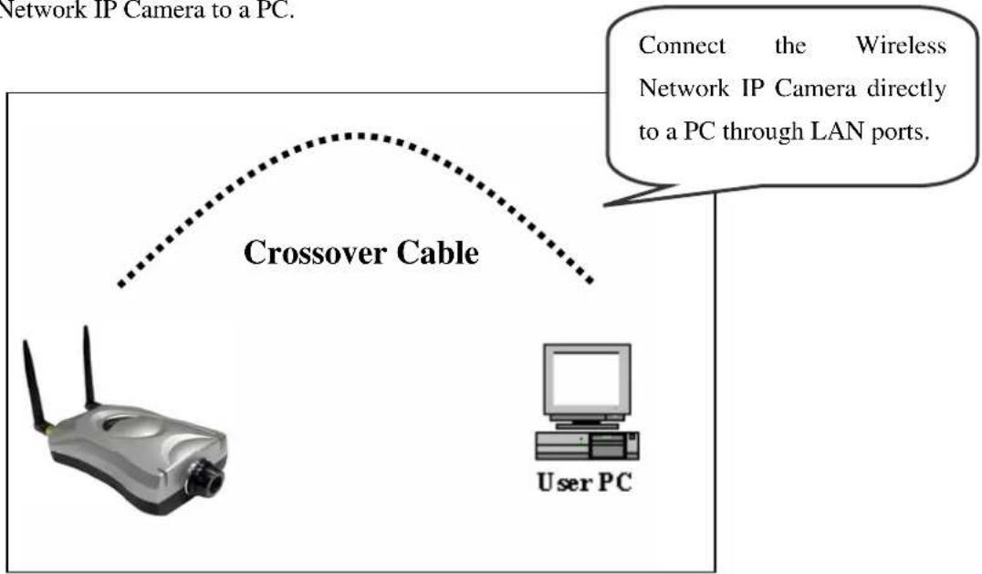
- Connecting with Crossover UTP Cable. Use the crossover cable to directly connect the Wireless Network IP Camera to a PC.
flowchart
graph TD
    A["User PC"] -->|Connect the Wireless Network IP Camera directly to a PC through LAN ports.| B["Crossover Cable"]
    B --> C["Network IP Camera to a PC"]
WIRELESS NETWORK IP CAMERA User's Guide
Using IP Installer
To install an IP address, you should use the IP Installer provided with Wireless Network IP Camera. You can also download the latest version of this program from the web site (http://intellinet-network.com).
Note : System requirements for IP Installer: Microsoft Windows9x/NT/2000/XP.

① Execute the IP Installer after the Network
IP Camera has completed the boot process
(wait at least 15 seconds).
② When the IP Installer is executed, the panel shows every Wireless Network IP Camera connected on the local network.
③ From the Wireless Network IP Cameras listed, select one to assign a new IP address (every Wireless Network IP Camera has a factory default IP address).
Note: The MAC Address can be found on the underside label of the Wireless Network IP Camera. To choose a Wireless Network IP Camera, click on its list.
Enter the Administrator ID and password in the blank (Default Administrator ID and password are all “admin”) to assign (or change) the IP Address for the Wireless Network IP Camera..
Enter the IP address, Gateway address, Subnet Mask address, and DNS Server address that are assigned from network administrator. (When the addresses are not assigned properly, you cannot access the Wireless Network IP Camera).
The Server IP Address represents an IP address of a PC that runs a TFTP Server which is being used to upgrade the firmware of the Wireless Network IP Camera via Hyperterminal. This upgrade method is designed for engineers. Therefore, the Server IP Address field can normally be left blank.
WIRELESS NETWORK IP CAMERA User's Guide
After entering all addresses for the Wireless Network IP Camera, click the “Change Network Configurations” button.
The following message is displayed once all the information is set up properly. Click OK.

NOTE
After changing the Network Configuration, it will take about 15 seconds to reboot the Wireless Network IP Camera.. After that you may access the Wireless Network IP Camera Home Page.
WIRELESS NETWORK IP CAMERA User's Guide
Assigning IP Address by using Hyper Terminal (Advanced Users only)
You can assign an IP address by using Hyper Terminal. In this case, you should configure Hyper Terminal first
Configuring Hyper Terminal
Hyper Terminal is a basic program for Windows 9x/NT/2000 and XP. A PC can communicate with external devices through the serial port by using this program. The steps you should take to set the Hyper Terminal are as follows in the case of Windows 2000 OS:
① Start → Programs → Accessories →
Communications → Hyper Terminal.
Select one of the icons and then enter an appropriate name in the box.

② Select a serial port of PC, then click the
"OK" button. (Usually COM1 or COM2 is recommended).

WIRELESS NETWORK IP CAMERA User's Guide
③ Configure bit/sec as 19,200 and leave the other settings at the default values.
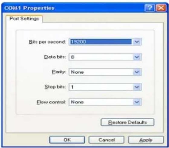
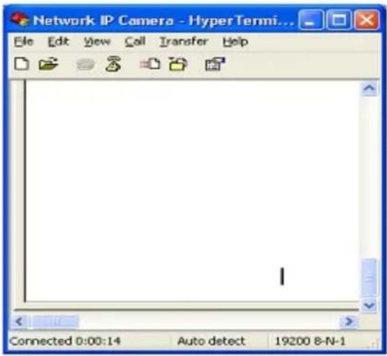
④ The panel looks like this image when configured properly. (If it does not, repeat steps 1-4.)
WIRELESS NETWORK IP CAMERA User's Guide
Assigning IP Address
Follow these steps to assign an IP address using Hyper Terminal
- Execute "Hyper Terminal" on your PC
- Connect an RS232 Cable to the serial port of the PC that you have selected in Chapter 4.3.1 - Configuring Hyper Terminal and the Wireless Network IP Camera serial port while Hyper Terminal is executed.
- Supply power to the Wireless Network IP Camera.
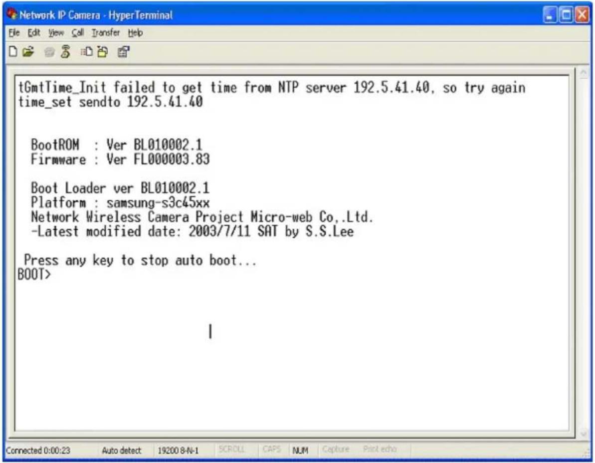
- A count down will start with the message "Press any key to stop auto-boot."
- Press any key. "Boot" prompt should appear as below.
WIRELESS NETWORK IP CAMERA User's Guide
- You can see Network Configuration while [Boot] prompt is running by pressing 'p' key again.
![BootROM : Ver BL010002.1 Firmware : Ver FL000003.83 Boot Loader ver BL010002.1 Platform : samsung-s3c45xx Network Wireless Camera Project Micro-web Co.,Ltd. -Latest modified date: 2003/7/11 SAT by S.S.Lee Press any key to stop auto boot.. BOOT> b2006worldcup ADMIN> m 00:0c:1c:00:2f:8c ADMIN> s mncl10b007052 ADMIN> p Serial Number: MNCL10B007052 MAC Address: 00:0c:1c:00:2f:8c Boot Mode[1:Auto by flash, 2:Auto by tftp, 3:Manual] : 1 | Internet Address: 211.232.103.18 Network Mask: 255.255.255.224 Default Gateway: 211.232.103.1 TFTP-Server Address :192.168.1.3 Source Address in ROM: 0x1010000 Target Address in RAM: 0x8000 File Size of Byte: 0 File Name: image.ram.microweb ADMIN>](/content/2026/06/1260183/images/903b15ba7d1dbc91e43d857c19f65fb01d529f30caed1218c855c67a9196d72c.jpg)
Here, inet on ethernet (e), host inet (h) and gateway inet (g) values are network configuration values. You should change these values in most cases. If you don't know what values you should assign, contact the network administrator.
Inet on ethernet (c) is the IP address and Subnet Mask address of the Wireless Network IP Camera. IP address and Subnet Mask addresses are separated by colon (:). For example, IP address is represented by decimal numbers delimited by dots (.), e.g., '192.168.1.27'. Hexadecimal numbers, e.g., 'ffffff00' in the case of '255.255.255.0,' represent the Subnet Mask address. Note that the numbers in the Subnet Mask value are not delimited by dots. See the example in the above picture.
Host inet (h) is the address to which Wireless Network IP Camera tries to connect to upgrade its firmware program in flash memory. The Wireless Network IP Camera first searches for this host on
WIRELESS NETWORK IP CAMERA User's Guide
the network on booting sequence. For more information on Wireless Network IP Camera upgrade, refer to “E. Updating Wireless Network IP Camera’s Newly Upgraded Program”.
Gateway inet (g) is the gateway address of the Network Camera
- Type ‘c’ to change the network configuration in [Boot] prompt. If you type ‘c’, the Wireless Network IP Camera shows you the information you can change and the current assigned values. You can change as the following figure.
![Serial Number: MNCL10B007051 MAC Address: 00:0c:1c:00:2f:8b Boot Mode[1:Auto by flash, 2:Auto by tftp, 3:Manual] : 1 Internet Address: 211.232.103.18 Network Mask: 255.255.255.224 Default Gateway: 211.232.103.1 TFTP-Server Address :192.168.1.3 Source Address in ROM: 0x1010000 Target Address in RAM: 0x8000 File Size of Byte: 0 File Name: image.ram.microweb BOOT> c Boot Mode[1:Auto by flash, 2:Auto by tftp, 3:Manual] : Internet Address[211.232.103.18] : Network Mask[255.255.255.224] : Default Gateway[211.232.103.1] : TFTP-Server Address[192.168.1.3] : Source Address in ROM[0x1010000] :0x Target Address in RAM[0x8000] :0x File Size of Byte[0] : File Name[image.ram.microweb] : BOOT>](/content/2026/06/1260183/images/0564981922106af75d61cb275e5d6764d1448da36659877008fb60fca5dd6fd7.jpg)
- When you terminate the Hyper-Terminal program after changing the network configuration, Hyper-Terminal asks you whether to save the session. If you save the session, you can re-use the hyper-terminal. To re-use the session you saved, click Start --> Programs --> Accessories --> Communications --> HyperTerminal --> Wireless Network IP Camera.. ht in the case of Windows 2000.
WIRELESS NETWORK IP CAMERA User's Guide
Accessing the Wireless Network IP Camera Home Page
After assigning the Wireless Network IP Camera an IP address, you may access Wireless Network IP Camera and monitor real-time images on the Internet. You may configure Wireless Network IP Camera within its own pages through any standard Web browser on a local or remote network.
Starting Web Browser
Start your web browser and enter your Wireless Network IP Camera's IP address.
Default IP Address
http://192.168.1.221/
Please note: 192.168.1.221 is the default IP Address of Network IP Camera. If you have change the IP address using IPINSTALLER.EXE (see above), you need to enter the new IP Address in your web browser.
Login Page
This page is to enter the Wireless Network IP Camera's built-in Home page. To access this page, you may be prompted to enter a user ID and password.

WIRELESS NETWORK IP CAMERA User's Guide
1. ID and Password
If you key in a user ID and password, you can access the camera to monitor real-time video.
With Administrator's ID and password, you can access real-time video with Administrative authority. The default value of both user ID and password are “admin” and the administrator may change it at the Administrator Menu. Each ID and password must be composed of no more than 10 bytes (e.g., 10 English letters). For guest users, the Wireless Network IP Camera has default ID and password “guest”, but guests cannot access the administrator tools..
2. Behind Firewall
If your PC is connected on a network with a firewall, you may not view real time video properly because the video TCP port is blocked. If you are behind a firewall, you may view real-time video through the Wireless Network IP Camera's Server Push Viewer that transmits video through the web's TCP port instead of the video TCP port. By clicking on the "Behind Firewall" menu, you may directly connect to the Server Push Viewer when you access the Wireless Network IP Camera home page.
3. Active-X for MS Explorer Users
For all Microsoft Explorer users, the Active-X Control program is required. The program will be installed automatically when a user accesses the Wireless Network IP Camera. For Active-X installation on your PC, just click 'Yes' to the question "Do you want to install the program?" on the pop-up window. If you cannot see images after installation, you should download and install Active-X manually.

The Active-X Installer may not show up, if the Security Settings on your PC are set too high. You need to allow the execution of Active-X scripts.
The Active-X Installer requires the user currently logged on to the system to have system administrator rights (Windows 2000 and Windows XP).
WIRELESS NETWORK IP CAMERA User's Guide
The manual installation requires the user to have system administrator rights (Windows 2000 and Windows XP).
Active-X Manual Installation
If the Active-X program fails to install automatically, you may install it manually.
The manual installation program can be downloaded as follows:
Active-XVisit http://www.intellinet-network.com/driver/NetCam.exe to download and install Active-X manually as follows:
① When the panel appears, select "Run this ..." if you want to install right away.

② Install Shield Wizard appears after finishing download.
③ Check "Repair" then click "Next"

④ When installation is completed, press "Finish"
⑤ Go back to the Login page to access Camera homepage.

WIRELESS NETWORK IP CAMERA User's Guide
4) Java Applet for Windows, Macintosh or Unix System user.
Java Applet viewer is for a user who accesses the Wireless Network IP Camera through a computer that does not Utilize MS Windows Active-X, such as Macintosh computers. Java Applet viewer is run with Java Virtual Machine that is installed on the user's computer.
Macintosh and Unix/Linux Systems
The Wireless Network IP Camera Active-X program is based on MS windows OS. Therefore it is impossible to access the Wireless Network IP Camera and monitor real time images through the default viewer.
If a user accesses the Wireless Network IP Camera through Macintosh or Unix systems, Wireless Network IP Camera detects that OS is not MS Windows and it operates the Java based image viewer to show real-time images. Some functions are not available for Java Applet.
NOTE
It is highly recommended that you select Active-X viewer for Windows 95, 98, 2000 or XP when using Internet Explore 4.0 or higher. If not, choose Java Applet Viewer.
NOTE
Windows XP does not have the JAVA Virtual Machine installed by default. If you are planning on using JAVA to access your camera, you may need to install the JAVA VIRTUAL MACHINE for Windows first. You can download it here:
http://www.java.com/en/download/installed.jsp
WIRELESS NETWORK IP CAMERA User's Guide
Wireless Network IP Camera Home Page
Having completed the login procedure, you now see the Wireless Network IP Camera home page
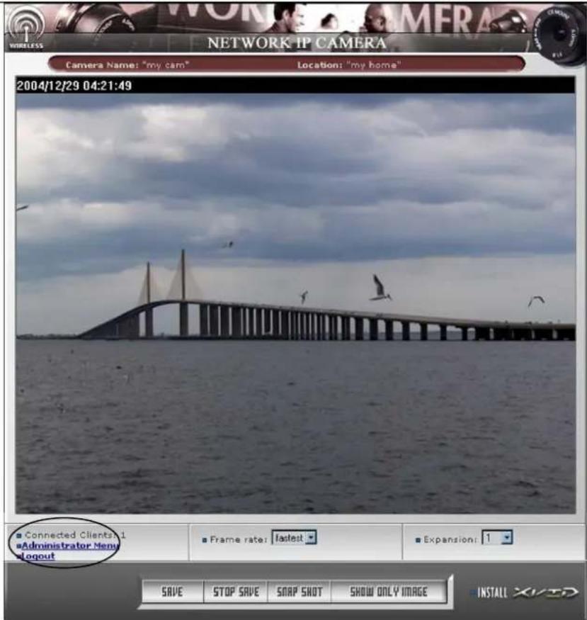
1. Connected Client
Shows the number of users currently connected to the camera (100 users can access the camera simultaneously).
2. Administrator Menu
Provides access to the Administration menu. However, only users who have Administrator authority can access the menu with the Administrator ID and password (please refer to Configuring the Administration Menu).
3. Logout
Logs the user off the camera.
WIRELESS NETWORK IP CAMERA User's Guide
4. SAVE, STOP SAVE, SNAP SHOT, SHOW ONLY IMAGE
① SAVE, STOP SAVE
Users can save real time images from the Wireless Network IP Camera.

Press SAVE then select the folder where you want to save images. (The image is saved as an AVI file.)
Once it starts to save the image, "Saving" message and XviD Status appear.
To stop saving, press STOP SAVE.

natural_image
A heron standing by the sea with green grass in the foreground (no text or symbols visible)(Saving Mode)

(XviD Status)
NOTE
■ You may view the saved image using Window Media Player or Real Player.
■ Click the "Install XviD" for AVI saving
■ The AVI saving will generate a new file with a different name in the same folder every 20 minutes.
(For example) file name 2002_04_22_15_00, file name 2002_04_22_15_20...
WIRELESS NETWORK IP CAMERA User's Guide
② SNAP SHOT
To save only one image, press
SNAP SHOT and then select a folder.
Save the image as JPG file.

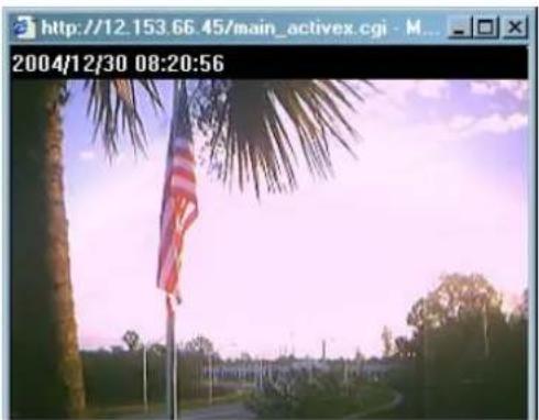
③ SHOW ONLY IMAGE
When you want to see only the video panel, press SHOW ONLY IMAGE.
natural_image
Exterior view of a palm tree with a flagpole in the foreground under a twilight sky (no signage or text visible)5. Frame Rate
You may choose image transmission speed. If you choose 'Fastest', you will get images at the fastest frame rate. The transmission speed depends on your network line's capacity and PC's performance. The maximum selectable frame rate depends on the setting for this user in the USER CONFIGURATION of the Administrator Menu.
6. Expansion
You may select the image size from 0.5 to 2. This function may be used when you want to expand image size on your PC (resolution cannot be changed). The Expansion function does not change the true resolution of the image, it is a digital zoom.
The image resolution can be changed in the IMAGE CONFIGURATION (Administrator Menu).
7. Camera Name
You can set a camera name (please refer to Chapter 6.7 - System Configuration)
8. Location
This shows where the camera is located (please refer to Chapter 6.7 - System Configuration).
WIRELESS NETWORK IP CAMERA User's Guide
ADJUSTING THE CAMERA LENS
Adjusting the Focus
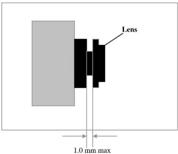
In order for the Focus Assistant to access the full focusing range for your application environment, simply turn the lens in the clockwise or counter clockwise direction. Unless you are replacing the lens, do not unscrew it more than 1.0 mm.
*Adjust the camera focus while reviewing the picture quality on your web browser.
NOTE
- A Good level of focus is normally achievable throughout several planes within the camera's focusing spectrum.
- Since optimum focusing is dependent upon the camera's field of view, it is important to scan the focusing plane from the closest to furthest perspectives before attempting any fine-tuning.
WIRELESS NETWORK IP CAMERA User's Guide
Replacing the Lens
Because the Wireless Network IP Camera is designed with a CS-Mount, the lens supplied with your product can be replaced with any standard C or CS lens typically used within the surveillance industry.
Follow the instructions below to replace the supplied lens with any C or CS type lens:
- Unscrew the Wireless Network IP Camera lens by turning the lens counter-clockwise
- C-lens only: Attach the new lens to a C-CS adapter
- Screw the new lens onto the Wireless Network IP Camera. If applicable, adjust the iris according to the prevailing light conditions.
- Refer to Adjusting the Focus on page 29.
- Reload your Web browser and monitor the results from the product Home Page.
WIRELESS NETWORK IP CAMERA User's Guide
CONFIGURING ADMINISTRATION TOOLS
You can control the configurations of the Wireless Network IP Camera by Administration Tools.

Only authorized users can access administration tools. Non-authorized users attempting access will see the message: "You are not an administrator".
Press Administrator Menu to control all configurations for Wireless Network IP Camera.
WIRELESS NETWORK IP CAMERA User's Guide
Administrator Menu Overview
The table below provides a one-step overview of the Administration Tools:
| Image Configuration | To configure compression rate, image size, brightness, contrast, etc. |
| Network Configuration To | configure camera IP, web server port, image transfer port |
| Wireless Configuration To | configure wireless setting |
| User Configuration To | configure user ID & password |
| Event Trigger Configuration | To configure event trigger condition, image capture option, trigger output |
| Time Configuration To | configure date and time |
| System Configuration | To configure the camera name, location, PTZ and see the system information. |
| Home Go to Wireless Network IP Camera home page | |
To prevent any unauthorized use, Wireless Network IP Camera access is restricted to defined users. The Administrator(s) has exclusive access to the product administration tools and can determine the registration, and access rights for all users.
Enter the default ID and password, then click "SUBMIT"
(Default ID and password are all "admin")
CAUTION
Although, the Administrator's default username and password (set to "admin" for all) can be used for logging onto the unit for the first time, it is highly recommended that you change this password for your Wireless Network IP Camera as soon as possible – since all Wireless Network IP Camera products are shipped with the same default ID and password.
NOTE
Make sure to click "submit" after changing configuration or your changes will not be saved.
WIRELESS NETWORK IP CAMERA User's Guide
Image Configuration
Example of Wireless Network IP Camera definable image attributes using the Focus Assistant:
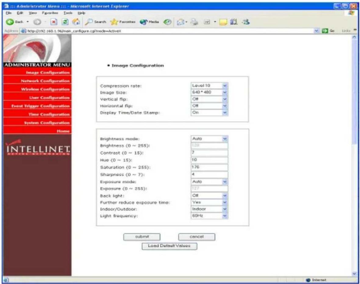
1. Compression rate
The file size of a JPEG-compressed image depends upon the actual content of the image. Images containing much detail will generate larger files. Image quality is controlled through the level of compression; where, high compression yields small files, while low compression maintains higher image quality at the expense of larger files. The table below contains compression ratios for each step, derived from real-life tests:
| Compression Rate | Level 1 | Level 2 | Level 3 | Level 4 | Level 5 | ||
| QVGA | 15 | 18 | 21 | 24 | 27 | ||
| VGA | 15 | 20 | 25 | 30 |
| Level 6 Level 7 Level 8 | Level 9 Level 10 | |||
| 30 | 33 | 36 | 39 | 42 |
| 40 | 45 | 50 | 55 | 60 |
WIRELESS NETWORK IP CAMERA User's Guide
2. Image Size
You may choose the image size VGA(640x480) or QVGA(320x240) and 160*120
Large image sizes (VGA) yield lower frame rates, while small sizes maintain higher frame rates
3. Vertical Flip
Turns the image view upside down (affects only the web browser live view)
4. Horizontal Flip
Switches the image view right from left (affects only the web browser live view)
5. Display Time/Date Stamp
Turns on/off the time and date stamp in the live image (affects only the web browser live view)
6. Brightness Mode, Brightness
The higher the number, the brighter the image. (Input digits from 0 to 255)
7. Contrast
The higher the number, the clearer the contrast. (Input digits from 0 to 15)
8. Hue
The lower the number, the pinker the color. The higher the number, the greener the color.
(It is possible to input digits from 0 to 15)
9. Saturation
The higher the number, the deeper the color. (It is possible to input digits from 0 to 255)
10. Sharpness
The higher the number, the more vivid the color. (It is possible to input digits from 0 to 7)
11. Exposure Mode
You may select "Auto" and "Manual"
12. Exposure
The higher the number, the brighter the image.(It is possible to input digits from 0 to 255)
13. Back Light
When the light is not sufficient, “Back Light” may increase visibility.
14. Further Reduce Exposure Time
Reduces exposure time from 1/20 to 1/100 under heavy light.
15. Indoor/Outdoor
Controls the brightness under the circumstance
16. Light Frequency
Sets a frequency for the image sensor
16. Submit
Transfers current configuration data to a Wireless Network IP Camera (after transferring data)
17. Cancel
18. Load Default Values
Sets the configuration as default values. (No need to press SUBMIT)
WIRELESS NETWORK IP CAMERA User's Guide
Network Configuration
This screen defines the network type and addresses of the Wireless Network IP Camera. Here you can configure the Camera's IP address, the DNS server address, and the Server IP address. Each configuration takes just a few seconds for booting after pressing SUBMIT.

1. Set IP Address, Subnet Mask, and Gateway Address.
To set the IP Address, Subnet Mask, and Gateway Address manually, you may select "manually" in combo box.
WIRELESS NETWORK IP CAMERA User's Guide
Manual configuration can be done using the IP installer or the information on this page.
(If you have trouble configuring network system information, please ask your Network Administrator for assistance.)
To set DHCP, you may select 'using DHCP'.
When selecting “using DHCP”, the IP Address, Subnet Mask Address and Gateway Address may not be activated. Under DHCP selection, the IP address may be sent to an e-mail address whenever IP address is changed. Users in a local area network may check the IP address through IP installer.
NOTE
If you select “DHCP”, you may see the rebooting message “Now the Network Camera is rebooting to apply the changes...” on the Web Browser. After completing rebooting, the Operating Status LED blinks once per second to verify that the changes were applied.
To select DHCP, you must have DHCP server in the network. Otherwise, the IP address will reboot automatically as the previous IP address. It may take 4 minutes for booting.
After rebooting, please reenter the previous IP address.
You may see the fail message from the Network Configuration page.
2. Send IP Address to E-mail
To send camera system information (Camera Name, Camera Location, DHCP IP address), check the text box and enter you e-mail address. (You should configure your SMTP server information first)
3. Server Port Number
Set the Port Number for the web server. (The default port number is '80' and users can select from 80 to 1023)
4. Image Transfer Port Number
Set the port number for the image transfer. (The default port number is “8080” and users can select from 8000 to 65535)
5. Ugrade Port Number
Set the Port Number for upgrading firmware. (The default port number is "9000" and users can select from 8000\~65535)
WIRELESS NETWORK IP CAMERA User's Guide
6. PTZ port number (not useable in Wireless Camera)
CAUTION
Be careful not to use the same port number for Image Transfer Port Number and Upgrade port number. If it is duplicated, a warning message will appear.
7. ETSP port number
Set the port number for ETSP [Event Trigger Setting Program]. (Default is “11000” and users can select from 8000 to 65535. For the detail of ETSP, please refer to the ETSP manual.)
8. 1st, 2nd DNS Server Address
To map between IP address and domain name, you should enter you DNS server address.
If a user set the DNS server into the camera, users can configure the SMTP server, FTP server, and NTP server with domain names.
DNS (Domain Name System)
DNS (Domain Name System) is used to map between IP address and domain name. Every network device connected to the Internet has an IP address that is used instead of its domain name. Common users are not familiar with IP addresses but the domain names.
If a user accesses a certain network device with its domain name, a DNS server translates the domain name into an IP address.
9. SMTP server
You need to specify your SMTP Server if you want to use any of the camera's email features. Other than that, it can be left blank.
10. Use SMTP Authentication
If you need user authentication for accessing the SMTP server, check this box. and enter your ID and password for your SMTP server. Realm should be left blank, and authentication should be set to LOGIN in most cases.
- Authentication method: Choose the SMTP authentication method.
- ID: : Enter the user ID for SMTP authentication.
- Password: Enter the user password for SMTP authentication..
- Realm: : Enter the Realm for SMTP authentication.
WIRELESS NETWORK IP CAMERA User's Guide
11. DDNS Registration
To register the Wireless Network IP Camera to a DDNS (Dynamic Domain Name Server), check the
Enable box. A dynamic IP address complicates remote access since you may not know what your current WAN IP address is when you want to access your network over the Internet. The solution to the dynamic IP address problem comes in the form of a dynamic DNS service. (Please refer to the Appendix for details.)
12. ID, Password
Enter the ID and password to find the registered Wireless Network IP Camera in the DDNS server.
13. Host Name
Enter the host name to find the registered Wireless Network IP Camera in the DDNS server.
14. DDNS Manual Update
You can update the DDNS manually.
15. Status
Shows the status of successful DDNS access.
16. Submit
Sends configured data to the Wireless Network IP Camera.
WIRELESS NETWORK IP CAMERA User's Guide
Wireless Configuration
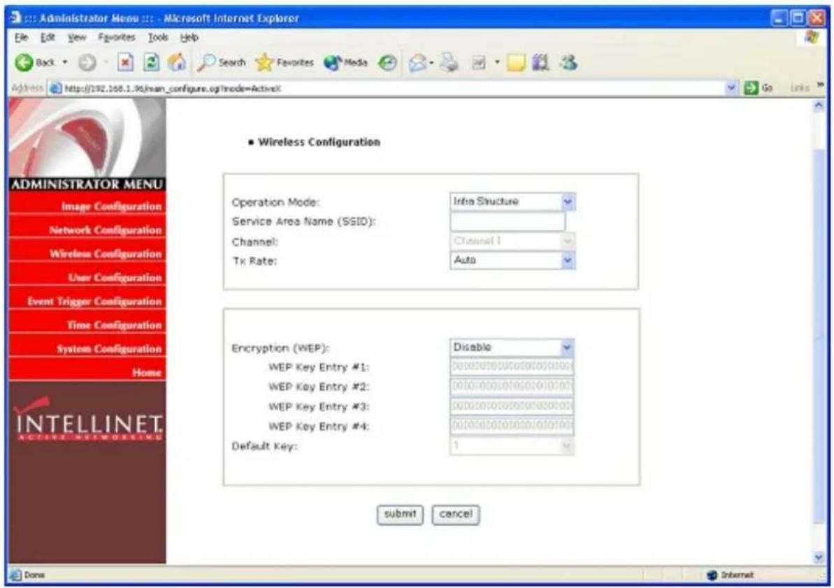
This screen is used to configure wireless settings to match your access pointer for a wireless network connection.
Wireless Setup
- Use the Connection Mode to determine the type of wireless communication for the Wireless Network IP Camera. There are two choices: Infrastructure Mode and Ad-hoc Mode. The default setting for the Connection Mode is Infrastructure Mode.
- Set the Service Area Name (SSID) as per the access point setting to which the user wants to connect.
- The channel is set to channel 1 as a default. In Infrastructure Mode the camera will automatically find the Access Point. The channel only needs to be set in Ad-hoc mode.
- The default setting for the "Tx rate" is Auto; however, it can be set to 5.5. or 11 mbps if required.
NOTE
Keep in mind the slide switch on the rear panel must be positioned to LAN-WAN or WLAN for the wireless communication to take effect.
WIRELESS NETWORK IP CAMERA User's Guide
Security Settings:
Wireless network communications are easily intercepted. WEP (Wired Equivalent Privacy) is an encryption method specified by the IEEE 802.11b standard to make any intercepted communications extremely difficult to interpret by unauthorized parties.
The WEP key needs to be entered in HEX code.
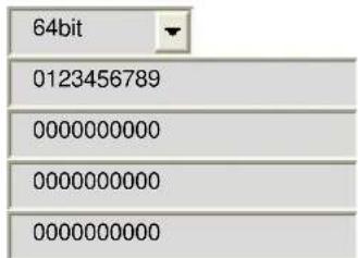
To set up 64-bit WEP, input 10 HEX characters, for example, 0123456789.
To setup 128-bit WEP, input 26 HEX characters, for example, 01234567890123456789012345
Example 1) Your access point uses 64-bit encryption, default key 1 and the key value is 0123456789. Your wireless camera WEP setting will be:
Encryption (WEP):
WEP Key Entry #1:
WEP Key Entry #2:
WEP Key Entry #3:
WEP Key Entry #4:
Default Key:
1
Example 2) Your AP uses 128-bit encryption, default key 2 and the key value is 01234567890123456789012345. Your wireless camera WEP setting will be:
Encryption (WEP):
WEP Key Entry #1:
WEP Key Entry #2:
WEP Key Entry #3:
WEP Key Entry #4:
Default Key:

Please note:
All four WEP Keys need to be set up the exact same way as they are defined in your Wireless Access Point.
WIRELESS NETWORK IP CAMERA User's Guide
Make sure the Encryption Code is the same as that of the access point the camera will be connected to under Infrastructure Mode. Your PC's encryption code also needs to be set up to match the camera's encryption code under either Infrastructure or Adhoc Mode.
The default setting for the Encryption Key is Disable; therefore, to secure the wireless transmission, be sure to enable the Encryption Key by entering the relevant data.
NOTE
Carefully input the Encryption Code. Any error will cause the communication link to fail
IMPORTANT
Infrastructure Mode:
This is an 802.11 networking framework in which devices communicate with each other by first going through an access point (AP). In infrastructure mode, wireless devices can communicate with each other or can communicate with a wired network. When one AP is connected to a wired network and a set of wireless stations, it is referred to as a Basic Service Set (BSS). An Extended Service Set (ESS) is a set of two or more BSSs that form a single sub network. Most corporate wireless LANs operate in Infrastructure Mode because they require access to the wired LAN in order to use services such as file servers or printers.
Ad-hoc Mode:
This is an 802.11 networking framework in which devices or stations communicate directly with each other, without the use of an AP. Ad-hoc Mode is also referred to as Peer-to-Peer Mode or an Independent Basic Service Set (IBSS). Ad-hoc Mode is useful for establishing a network where wireless infrastructure does not exist or where services are not required.
SSID (service set identifier):
This is a 32-character unique identifier attached to the header of packets sent over a WLAN that acts as a password when a mobile device tries to connect to the BSS. The SSID differentiates one WLAN from another, so all access points and all devices attempting to connect to a specific WLAN must use the same SSID. A device will not be permitted to join the BSS unless it can provide the unique SSID.
An SSID is also referred to as a network name because essentially it is a name that identifies a wireless network.
To connect a wireless client such as a Wireless Network IP Camera to a specific AP, the user of the camera should specify the SSID name in the camera's wireless IP setting.
WIRELESS NETWORK IP CAMERA User's Guide
User Configuration
This screen is used to configure IDs and passwords for an Administrator and up to 5 users.
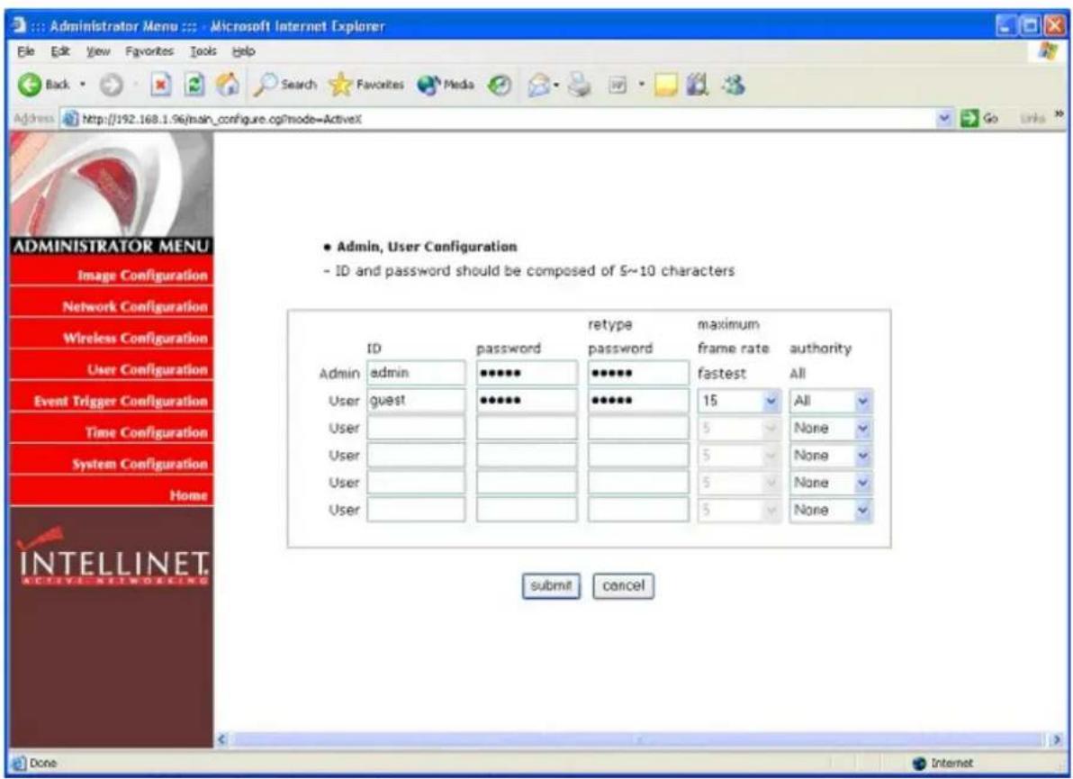
1. User Account (max. 10 characters)
There is one Administrator account and 5 user accounts. Account names can be changed.
2. Password (max. 10 characters)
If you want to open your Wireless Network IP Camera to everyone, you cannot change default user ID and password. However, you should change the administrator ID and password to a unique selection.
3. Frame Rate
Define the maximum frame rate for each user. This feature is useful if you want to reserve bandwidth for "power users."
4. Access Rights
The Administrator may assign users rights of viewing control. With the default setting, the administrator has all configuration authority, and the normal user doesn't have any right except to access the login page and the camera home page (live video).
WIRELESS NETWORK IP CAMERA User's Guide
Event Trigger Configuration
This screen is used to designate an e-mail address or FTP server to receive captured images by setting SMTP or FTP settings. You may connect external devices such as an infrared sensor or alarm sensor to use with the provided terminal block (please refer to Appendix F – The I/O Connector).
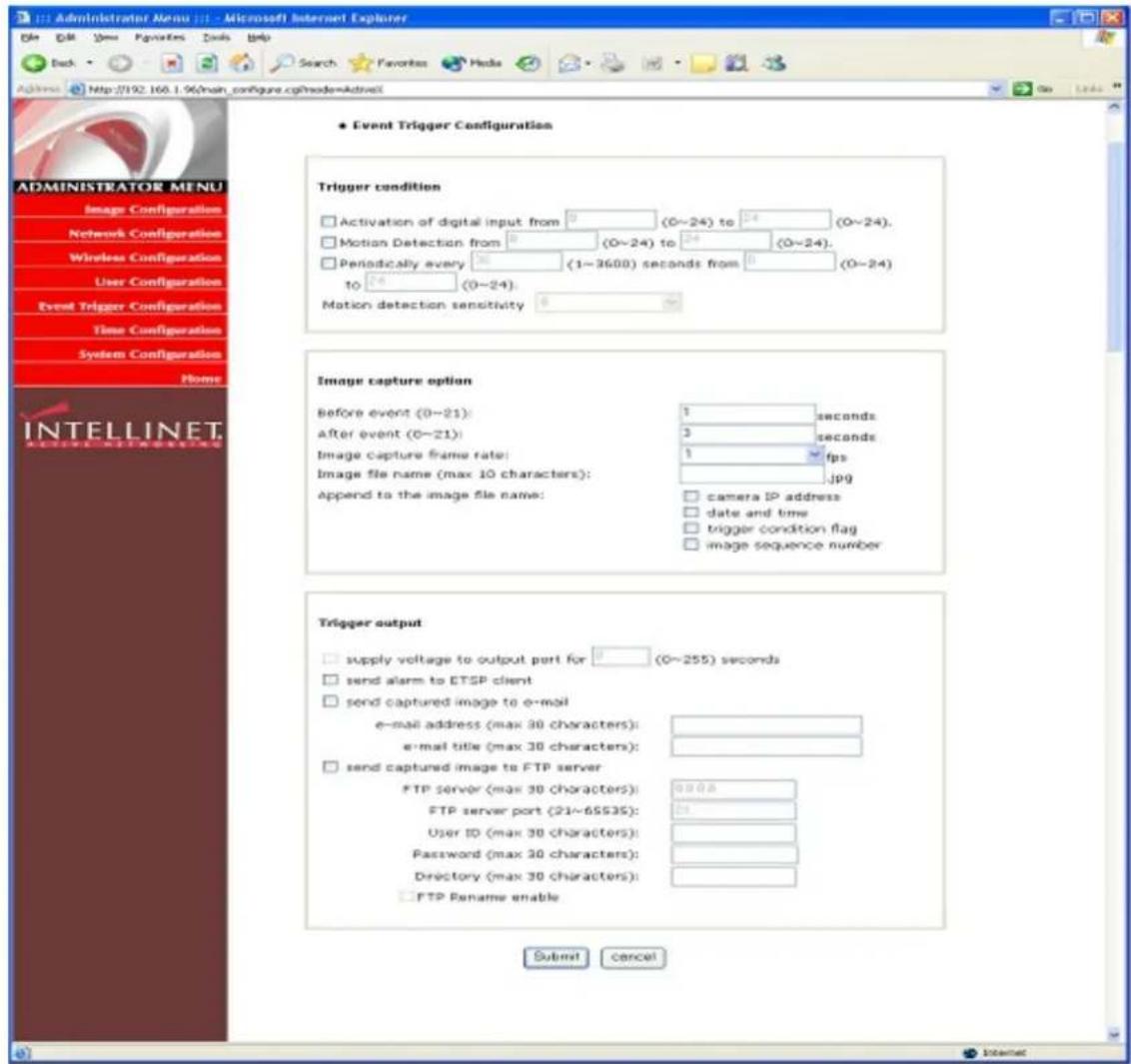
1. Trigger Condition
This is to select option how to send an event signal to the Wireless Network IP Camera.
① Activation of digital input port
The Wireless Network IP Camera receives an event signal from an external device such as an infrared sensor, alarm sensor, etc.. The trigger condition defines the "active" state of the IO Port.
WIRELESS NETWORK IP CAMERA User's Guide
② Motion detection from.....
This is to detect motion from camera by S/W data comparison. When you select Motion Detection, the Wireless Network IP Camera detects a motion triggered by the camera lens. To detect motion, the camera compares a previous and present image. Motion is detected when, the camera recognizes a data change. This feature does not work if the image is too dark. Also, the Motion Detection only works reliably at a maximum image resolution of 320x240.
CAUTION: Do not use the motion detection function for security monitoring of high value items. When using motion detection for security, the use of an external sensor, such as infrared, is recommended.
The "from" and "to" values specify the time window in which the motion detection is active.. Example: From 8 to 19 would activate the motion detection between 8 o'clock in the morning and 7 o'clock in the evening.
③ Periodically.....
The Wireless Network IP Camera itself is to be triggered automatically by a programmable setting.
④ Motion detection sensitivity
This is to configure the level of motion detection sensitivity. The level is composed of 10 settings from 0 to 9. The higher the setting, the greater the sensitivity.
In case of level 9 for sensitivity, the camera may detect a tiny motion, even light changes.
It is strongly recommended to configure levels 3 - 6 for sensitivity.
2. Image Capture Option
This is to configure image capture before and/or after an event is triggered.
① Before event
You may set the starting time to capture the image before an event is triggered.
(Input limitation is from 0 to 21 seconds.)
② After event
You may set the finishing time to capture the image after an event is triggered.
(Input limitation is from 0 to 21 seconds.)
③ Image capture frame rate
Set the frame rate from 1 to 15 fps when the image is being captured.
④ Image file name
You may designate an image file name to send via e-mail or FTP after an image is captured.
All captured images are saved as JPG files. (Example. "File name 000".JPG)
WIRELESS NETWORK IP CAMERA User's Guide
⑤ Append to the image file name
You may append some information to the Image file name
A. Camera IP address : Example: "file name _192.168.1.19".JPG
B. Date and time : Example: "file name_20020218150030."JPG
C. Trigger condition flag
- If choosing "Activation of digital input port", "D" may be appended to image file name.
Example: "file name_D."JPG
In case of choosing “Periodically every...”, “P” is appended to image file name.
Example: "file name_P".JPG
D. Image sequence number
If you select this option, you may classify the file that has same extend name.
Consecutive numbers are from "000" to "999"
Example: When you designate the file name as “camera” and select “Image sequence number,” the file name appears “camera001.JPG, camera002.JPG ....camera999.JPG”
Image capture option limitation
Configuration for image capture option affects memory capacity. If you configure this option to excess memory size, the Warning message “Not enough memory…” appears.
The total image capture frame rate must be limited 45 fps due to memory size.
(Before event time + After event time) x Image capture frame rate must be less than 45.
For example, if you configure “Before event time” as 3 seconds, “After event time” as 2 seconds and “image capture frame” as 3 fps, the total image capture frame rate is (3 + 2) × 3 = 15 fps.
WIRELESS NETWORK IP CAMERA User's Guide
3. Trigger Output
This is to configure digital output states and control script. The Wireless Network IP Camera sends captured images via e-mail or FTP server when connected external sensors detect events.
① External devices signal output
This is to supply voltage to output port when events are triggered. (This option is only activated when you select “Activation of digital output” option in previous “Trigger Condition” option.)
② Send alarm to ETSP client
This is to send an alarm to an ETSP client.
If you check the box, the alarm will be sent to the ETSP client when an event is triggered.
ETSP Client is currently under development (as of January 2005). It will be available for download at the following address: http://www.intellinet-network.com/ipcamera.
③ Send captured image via e-mail
This is to designate a person to receive a captured image via e-mail.
The Wireless Network IP Camera sends a captured image to a designated e-mail address through an SMTP server.
You may configure the SMTP server and E-mail address. (E-mail address must be composed within 50 bytes, which are equal to 50 English characters.
④ Send captured image to FTP server
This is to send a captured image from the Wireless Network IP Camera when an event is triggered.
Enter FTP server IP address, user ID and password and select a directory to save the image.
The FTP Server Address needs to be entered without "FTP://"!
Example for use of the directory field:
Root Folder for FTP User Account which the camera uses: root
Subfolder in which the images should be uploaded: root/images
In that case you need to enter "images" (without leading or trailing/) in the directory field.
FTP RENAME ENABLE:
If the camera uploads an image to your Web Site every xx seconds (refresh) and if you display this image on your web page, you should always check this box. Otherwise it can be left unchecked.
WIRELESS NETWORK IP CAMERA User's Guide
Time Configuration
This screen is used to configure date and time.
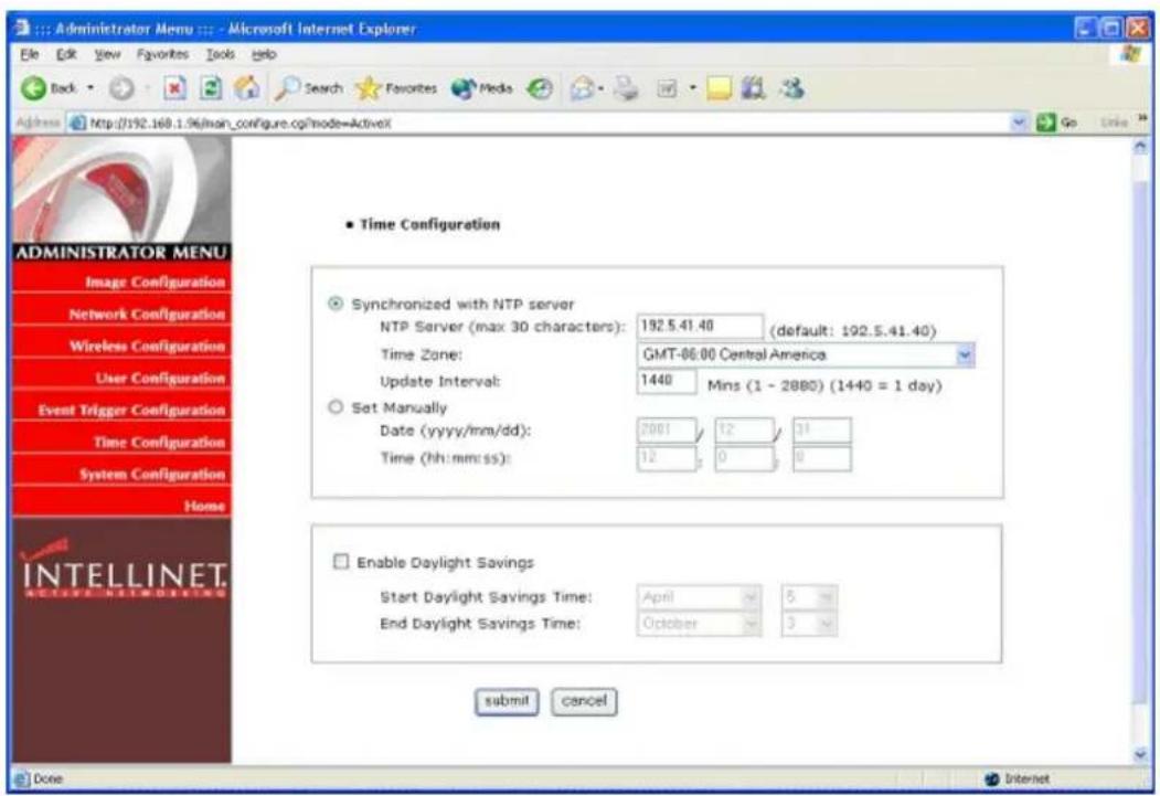
1. Synchronized with NTP server
The Wireless Network IP Camera automatically configures date and time through the NTP (Network Time Protocol) server. The NTP Server is based on Greenwich time. Select NTP server, IP address and Time Zone to set the date and time automatically, then press SUBMIT. It may not work due to the possible network error; in this case, you can select other NTP server and IP address or you can set the date and time manually. Once date and time are set,, you don't have to reconfigure when connecting to the Wireless Network IP Camera.
The "Update Interval" tells the camera how often to contact the NTP Server to resync the internal clock. For time critical applications the update interval can be set from 1 minute to 2880 minutes (= 2 days).
Free NTP Servers can be found at: http://www.ntp.org/.
2. Set manually
Enter the date and time manually, then click SUBMIT.
3. Enable Daylight Savings
This is to configure for Daylight Savings Time.
WIRELESS NETWORK IP CAMERA User's Guide
System Configuration
This screen is used to configure camera name, location and public image access. It also lets you remotely restart the camera and restore the factory default values.

1. Camera name
This is to configure camera name for the front-page view. Camera name should be limited to 15 bytes, which are equal to 15 English characters.
2. Camera location
This is to configure camera location for the front-page view. Camera location should be limited to 30 bytes, which are equal to 30 English characters.
3. Supply voltage to output port option
This option is to supply voltage to the Wireless Network IP Camera's output port. Just click "supply" to supply voltage to control the PTZ devices.
WIRELESS NETWORK IP CAMERA User's Guide
4. Direct public access to image via HTTP
The camera supports a method to access the live image directly without logging in to the camera. The URL is: http://camera_ip/jpg/image.jpg.
If direct public access is enabled, the image can be accessed without entering username and password. If direct public access is disabled, a valid username and password must be provided.
This feature is important for users who wish to use the camera in 3^rd party video monitoring applications as it turns your Network IP Camera into a "JPG Compatible Camera".
5. Image file name (maximum length 10 characters)
Set the image file name for the public access feature.
Example1 – Public Access is enabled: http://192.168.1.221/jpg/image.jpg Example2 – Public Access is disabled: http://guest:guest@192.168.1.221/jpg/image.jpg*
* MSIE does not support this type of command any longer due to a recent security upgrade by Microsoft.
6. System information
This is to check system information for Wireless Network IP Camera. You may see the model name, serial no., Mac address of Ethernet and WLAN Adapter, Bootrom & Firmware version. (Please refer to Appendix E., Updating Firmware.).
7. Reboot
This function allows you to reboot the camera via your web browser.
8. Restore Defaults
This functions allows you to restore the camera's factory default settings via your web browser. After the function has been performed, all settings are reverted to the original settings (including the IP Address, which is set to 192.168.1.221).
WIRELESS NETWORK IP CAMERA User's Guide
APPENDIX
A. Technical Specifications
Image
Resolutions supported: 640x480, 320x240, 160x120
Standard JPEG Compression - 10 levels of compressions
Frame Rates: Up to 8 fps at 640 x 480 resolution and 30 fps at 320x240 resolution
Network
10baseT Ethernet or 100baseTX Fast Ethernet
Twisted pair category 5 cables, Standard RJ45 connector
IEEE802.11b Wireless Ethernet, 11 Mbps
Two detachable antennas, connected via RSMA connectors
Supported Protocols: TCP/IP, UDP, PING, ARP, FTP, TFTP, and HTTP
Configuration by IP INSTALLER Windows Application and/or Web-based administration page.
Network Throughput: Up to 7 Mbps
Image Sensor
1/3" CMOS censor
326,688 pixels, 24-bit color, YUV digital output
Automatic exposure/Gain/White balance control
Image enhancement - brightness, contrast, gamma, saturation, sharpness, etc
664x492 pixel array elements
Electronic shutter: 1/30 s \~ 1/15734 s
Auto back light compensation: Automatic back light on or off depending on the lighting condition.
Lens specification
Replaceable standard CS mount lens
Focal length 6.0 mm, Angular field of view 54°, Object distance 0.1m to infinity
Maximum Relative aperture F1.8
C-Mount adapter available
Hardware
32bit RISC Net ARM CPU
ZORAN hardware compression chip
384 Kbytes video frame buffer
WIRELESS NETWORK IP CAMERA User's Guide
4M flash memory
SDRAM 8Mbyte
12V Power supply adapter included
Under 6W power consumption
System Requirements
Operating systems: Windows 9x, Windows NT/2000, Linux, Linux, MaOSc, etc.
Internet Explorer 4.0 or higher.
JAVA support for MacOS, Linux and Windows.
I/O Connector
D-sub 9pin RS232 connector
1 Input to trigger the camera on external events.
1 Output of 12 V to signal external devices, max 150 mA
Installation
Assigning IP address via IP INSTALLER program or web-based.
Approvals
EMC: FCC Class B, CE EN55022/1994, EN61000-3-2 & 3: 1995, EN50082-1: 1997
Operating Temperature
0-50°C
Others
Operating Status LED, Power LED, Image Capture LED, Network Packet Transmit LED EEPROM clear button
WIRELESS NETWORK IP CAMERA User's Guide
B. Frequently Asked Question (FAQ)
1. What is a Network IP camera?
A Network IP Camera is a stand-alone device which allows a user to view live, full motion video from anywhere on a computer network, even over the Internet, using a standard web-browser.
2. Are all Network IP cameras the same?
No, some network cameras have an embedded OS (operating system) as well as an embedded Web server. To be called a Network IP camera, the only requirement is that the camera connects to the network, and not a computer - an embedded OS is what separates network cameras.
3. Why Choose a Network IP Camera over a Web Camera?
An IP Camera is a true networking device containing an embedded OS (Operating System), supports multiple users, and can be viewed using any web browser. It does not require additional hardware to operate and therefore has the flexibility to be located anywhere with a network connection. A web cam must be connected to a host computer, supports only one user at a time, and cannot be shared on a network. Only the host computer can access the web cam.
4. What is the advantage of the embedded OS?
Cameras with an embedded OS communicate directly with the user; the images or video are sent directly from the camera to the person(s) accessing it. A Network camera without an embedded OS must rely on a third party server or a separate piece of software, meaning the images/video is sent to the third party server, then the user accesses the image from the third party server.
5. Do I need a public fixed IP address for each camera?
No, you of course, can have a real, public, static IP address for each camera, however, using just one static IP address for your router and a virtual server or port forwarding, you can use many cameras with just one static IP. Please also note that the IP camera must have an adjustable web server port (you must be able to change the web server port) to use multiple cameras behind a router.
6. Can I use the camera outside?
The Wireless Network IP Camera is designed for indoor use only.
7. What additional software is required?
Networking IP Cameras with an embedded Operating System (OS) should not need any additional software.
WIRELESS NETWORK IP CAMERA User's Guide
8. How does the built-in motion detection work?
It very simply compares what it sees now to what it saw in the last frame and based on a sensitivity you select will trigger an event. The event can be to send an e-mail, to send an Image to a FTP server, or to send a series of images (before and after the motion is detected) to an e-mail address or FTP server.-All required software is built into the camera.
9. What is the maximum length Ethernet cable I can use?
The same topology limitations that apply to any 10/100 Ethernet card apply, meaning the maximum segment length is 100 meters from the switch/hub to the camera
10. What is Power-over-Ethernet (PoE)?
Power-over-Ethernet (PoE), or "Active Ethernet," eliminates the need to run power to devices on a wired LAN. Using PoE, installers need to run only a single CAT5 Ethernet cable that carries both power and data to each device. This allows greater flexibility and significantly decreases installation costs in many cases.
11. Can Network IP Cameras use different lenses?
Advanced Network IP Cameras utilize CS-mount lenses, which can accommodate a variety of specialized lenses, such as wide-angle, fisheye or telephoto lenses.
12. What image sizes can be viewed from Network IP Cameras?
Advanced Network IP Cameras use multiple pre-set image sizes that typically include 160 x 120, 320 x 240 and 640 x 480 pixel image sizes.
13. Can I view a Network IP Camera from my PDA?
Network IP Cameras can now be viewed on most Windows systems,, including Pocket PC devices, such as the Compaq iPAQ, HP Jornada, Dell Axim, Casio Cassiopeia and many others. You can download the PDA Viewer at: http://www.intellinet-network.com/ipcamera.
WIRELESS NETWORK IP CAMERA User's Guide
C. Trouble Shooting
This appendix provides useful information to help you to resolve any difficulty you might have with your Wireless Network IP Camera. Fault symptoms, possible causes and remedial actions are provided within a quick reference table.
PINGing your IP Address
By sending a packet to the specified address and waiting for a reply, the PING (Packet Internet Groper) can determine whether a specific IP address is accessible; it also provides a particularly useful method for confirming addressing conflicts with your Wireless Network IP Camera on the network.
Disconnect your Wireless Network IP Camera,, follow the instructions below in association with Symptoms, Possible Cause and Remedial Actions, and run the PING utility to troubleshoot TCP/IP problems on your network.
① Start a DOS window
② Type ping x.x.x.x, where x.x.x.x. is the IP address of the Wireless Network IP Camera
③ The subsequent replies will provide an explanation as to the case of the problem. Replies can be interpreted as defined in the table below:
PING Reply
Interpretation and recommendation
| bytes = 32 time = 2 ms The IP address | is already used and cannot be used again. Your must obtain a new IP address |
| Destination host unreachable Wireless | Network IP Camera is not accessible within your subnet.You must obtain a new IP address |
| Request timed out This IP address is | not used by anyone and is available for use with your Wireless Network IP Camera |
WIRELESS NETWORK IP CAMERA User's Guide
Symptoms, Possible Causes and Remedial Actions
| Symptoms | Possible causes | Remedial actions |
| Wireless Network IP Camera cannot be accessed from a web browserThe Power LED is not constantly lit | The IP address is already used by another devices | 1.Disconnect your Wireless Network IP Camera from the network2. Run the PING utility (as described in PINGing your IP Address). |
| The IP address is located within a different subnet | Run the PING utility (as described in PINGing Your IP Address), If the utility returns “no response” or similar, the diagnosis is probably correct – you should then proceed as followsIn Windows 95/98 or Windows NT, check the IP address for your Wireless Network IP Camera is within the same subnet as your workstation:1.Click “Start”, “Settings”, “Control Panel” and “Network”.2.Specify the TCP/IP adapter and click on “Properties”. In Properties, Click “IP Address”.3.Check that the first 3 numbers within the IP address of your Wireless Network IP Camera match the first 3 of your workstation. If not, your Wireless Network IP Camera may be on a different subnet and the IP address cannot be set from this workstation. You must set the Wireless Network IP Camera IP address from a workstation on the same subnet. | |
| Other networking problems | Try replacing your network cableTest the network interface of the product by connecting a local computer to the unit, using a standard crossover (hub-to-hub) cable.If the above actions do not resolve the problem, the Wireless Network IP Camera may be faulty, In this case, try to localize the problem by connecting the camera to the serial port of a local computer, using the supported RS232 cable | |
| Faulty power supply Verify that you are using a provided power supply | ||
| The network LED is off | Faulty cabling 1.To verify | that the cables are functional, PING the address of a known existing unit on your network.2.If the cabling is OK and your network is reachable, your should receive the reply similar to this:... bytes = 32 time = 2 ms |
| The operating status LED is off | Faulty connection Verify | that the power is connected |
WIRELESS NETWORK IP CAMERA User's Guide
| Your Wireless Network IP Camera works locally, but not externally. | Firewall protectionDefault routers requiredThe Internet site is too heavily loaded | Check the Internet firewall with your network administrator.Determine whether you need to configure the default router settingsConfigure the Wireless Network IP Camera to upload your video images to an FTP server or an ISP |
| A series broad vertical white lines appear across the image. | The CMOS sensor becomes overloaded when the light is too bright. This can happen e.g. with sun light reflexes. | Direct exposure to extreme sunlight or halogen light may cause serious damage to the CMOS sensor.Reposition your Wireless Network IP Camera into a more shaded location immediately.Note: damage caused to Wireless Network IPCamera through over exposure to direct sunlight or halogen light is not covered under the product warranty. |
| Bad focus | Focus has not been correctly adjusted | Adjust the camera manually until the image views clear. |
| Noisy images Video images may be noisy if you are using the Wireless Network IP Camera in a very low light environment | You need more light. Use the back light function.If not helpful, you may wish to consider replacing the basic lens with a more sensitive lens, if the lighting conditions within the installation area cannot be improved | |
| Poor image quality The Display Properties are incorrectly configured for your desktop | Open the Display Properties in your desktop and configure your display to show at least 65'000 colors, i.e., at least 16-bit.Note: Using only 16 or 256 colors on your computer will produce dithering artifacts in the image. | |
| The camera is not focused correctly | Referring to the above, adjust the camera manually | |
NOTE
If you still have a problem after reading this information, please contact your dealer or check the FAQ on the INTELLINET ACTIVE NETWORKING web site at http://www.intellinet-network.com.
Before contacting the technical support team, please make sure that you run the latest firmware on your Wireless Network IP Camera. You can obtain the latest firmware here: http://www.intellinet-network.com/ipcamera
WIRELESS NETWORK IP CAMERA User's Guide
D. Utilizing IP Addresses on Local Area Network
Introduction
Access to the Internet is achieved via Internet IP addresses. Currently, IP addresses are limited. There are 5 classes of networks, and each network contains IP addresses. A network can only hold a limited number of IP addresses. The number of IP addresses depends on the network class. The 5 classes are labeled “A” through “E,” with the most common one being the “C” class network.
IP Construction and Network Class
1. IP Construction
| xxxx | xxxx | xxxx | xxxx | (xxx: 0-255) |
| X1 | X2 | X3 | X4 | e.g. 192.168.1.1 |
2. Network Class
A Class: A network that contains IP addresses from 0 to 127 at room 'X1'
Network ID: X1
Host ID: X2, X3, X4
There are 128 A-Class networks in the world.
B Class: A network that contains IP addresses from 0 to 127 at room 'X1'
Network ID: X1, X2
Host ID: X3, X4
There are 65, 534 B-Class networks in the world.
C Class: A network that contains IP addresses from 192 to 223 at room 'X1'.
Network ID: X1, X2, X3
Host ID: X4
The most common network in the world; there are 2,097,152 C-class networks in the world.
D Class: A network that contains IP addresses from 224 to 239 at room 'X1'. D-class networks are used for multicasting, and are not allowed for common use.
E Class: A network that contains IP addresses from 240 to 255 at room 'X1'. E-class networks are reserved.
WIRELESS NETWORK IP CAMERA User's Guide
C Class Network
1. Features of Addresses
IP address: The three-digit number in room 'X4' is for the Host ID. The number ranges from 0 to 255. Among the numbers, 0 is used for Network ID, 1 is used for Router IP (Gateway address) and 255 are used for Broadcast address. The numbers from 2 to 244 are IP addresses that can be assigned to Wireless Network IP Cameras, PCs, etc.
Network ID: Identifies a network. Generally the first number assigned is Network ID.
Gateway address: The IP address of the router for connecting Internet and local network.
Broadcast address: The IP address for broadcasting. All devices connected on a local network have the same Broadcast address.
Subnet Mask: Divides a local network into two remote networks. The Subnet Mask shows the IP quantity in a certain network. The number that can be used as Subnet Mask is limited (0, 4, 8, 16, 32, 64, 128)
2. Network Configuration
① To use as one network
Network ID: xxx.xxx.xxx.0
Gateway Address: xxx.xxx.xxx.1
Subnet Mask: 255.255.255.0
Broadcast Address: xxx.xxx.xxx.255
IP Addresses: xxx.xxx.xxx.2 - xxx.xxx.xxx.254
② To use as two Sub-networks (1/2 + 1/2)
Sub-Network ID: xxx.xxx.xxx.0
Gateway Address: xxx.xxx.xxx.1
Subnet Mask: 255.255.255.128
Broadcast Address: xxx.xxx.xxx.127
IP Addresses: xxx.xxx.xxx.2 - xxx.xxx.xxx.126
Sub-Network ID: xxx.xxx.xxx.128
Gateway Address: xxx.xxx.xxx.129
Subnet Mask: 255.255.255.128
Broadcast Address: xxx.xxx.xxx.255
IP Addresses: xxx.xxx.xxx.130 - xxx.xxx.xxx.254
WIRELESS NETWORK IP CAMERA User's Guide
③ To use as three sub-networks (1/4 + 1/4 + 1/2)
Sub-Network ID: xxx.xxx.xxx.0
Gateway Address: xxx.xxx.xxx.1
Subnet Mask: 255.255.255.192
Broadcast Address: xxx.xxx.xxx.63
IP Addresses: xxx.xxx.xxx.2 - xxx.xxx.xxx.62
Sub-Network ID: xxx.xxx.xxx.64
Gateway Address: xxx.xxx.xxx.65
Subnet Mask: 255.255.255.192
Broadcast Address: xxx.xxx.xxx.127
IP Addresses: xxx.xxx.xxx.66 - xxx.xxx.xxx.126
Sub-Network ID: xxx.xxx.xxx.128
Gateway Address: xxx.xxx.xxx.129
Subnet Mask: 255.255.255.128
Broadcast Address: xxx.xxx.xxx.225
IP Addresses: xxx.xxx.xxx.130 - xxx.xxx.xxx.256
④ To use as four sub-networks (1/4 + 1/4 + 1/4 + 1/4)
Sub-Network ID: xxx.xxx.xxx.0
Gateway Address: xxx.xxx.xxx.1
Subnet Mask: 255.255.255.192
Broadcast Address: xxx.xxx.xxx.63
IP Addresses: xxx.xxx.xxx.2 - xxx.xxx.xxx.62
Sub-Network ID: xxx.xxx.xxx.64
Gateway Address: xxx.xxx.xxx.65
Subnet Mask: 255.255.255.192
Broadcast Address: xxx.xxx.xxx.127
IP Addresses: xxx.xxx.xxx.66 - xxx.xxx.xxx.126
Sub-Network ID: xxx.xxx.xxx.128
Gateway Address: xxx.xxx.xxx.129
Subnet Mask: 255.255.255.192
Broadcast Address: xxx.xxx.xxx.191
IP Addresses: xxx.xxx.xxx.130 - xxx.xxx.xxx.190
WIRELESS NETWORK IP CAMERA User's Guide
Sub-Network ID: xxx.xxx.xxx.192
Gateway Address: xxx.xxx.xxx.193
Subnet Mask: 255.255.255.192
Broadcast Address: xxx.xxx.xxx.255
IP Addresses: xxx.xxx.xxx.194 - xxx.xxx.xxx.254
WIRELESS NETWORK IP CAMERA User's Guide
E. Updating Firmware
CAUTION
The process to update the current firmware is already installed into your Wireless Network IP Camera
Follow the instruction in this manual. During the process, do not expose the camera to physical shock nor disconnect network and power. Otherwise, your Wireless Network IP Camera can be damaged seriously, which may result improper operation or failure.
If you are unable to update the firmware or the Wireless Network IP Camera does not operate properly after updating, please contact your dealer.
Identify the Version of Firmware
You can identify the version of Wireless Network IP Camera's Firmware on the System Configuration Page. It is also displayed on the camera's login page.
(You may check the version of your Wireless Network IP Camera firmware first and then update if necessary.)
Follow these steps to check the installed version of firmware
① Connect to your Wireless Network IP Camera home page.
② Click "Administrator Menus."
③ Move to System Configuration Page and check the version of firmware.
Download New Firmware
You can download the latest firmware over the Internet at the INTELLINET ACTIVE
NETWORKING website: www.intellinet-network.com/ipcamera.
WIRELESS NETWORK IP CAMERA User's Guide
Install New Firmware
The Wireless Network IP Camera can be upgraded via the LAN or remotely over the Internet.
Follow these steps to install new firmware:
① Confirm that the Wireless Network IP Camera is connected to your PC. (As long as you can access your Wireless Network IP Camera Home page, you can upgrade its firmware.)
② Execute the upgrade utility (included in ZIP file).
③ Enter the camera's IP address, upgrade port number, Admin ID and password configured on the Network Configuration page. And then press "start upgrade" button.
You may see the upgrading status.
Upgrading levels are divided into 4 steps from
"Transferring Firmware" to "Verify flash memory".
(Each step is indicated on progress bar.)
④ When upgrading is complete, a message appears.
"Firmware Upgrade Completed."
Click the "OK" button.
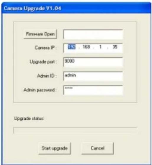

The Upgrade process must not be interrupted!
If the network connection fails during the upgrade, the camera will be damaged.
WIRELESS NETWORK IP CAMERA User's Guide
F. The I/O Connector
The I/O Connector provides the physical interface to a digital output, and a single digital photo-coupled input that is used for connecting a variety of external alarm devices to the Wireless Network IP Camera; including, IR-sensors, switches and alarm relay.
In combination with the configurable alarm facilities, you can quickly develop a variety of security applications that are triggered on time- or alarm-based events. The connector can also be utilized as an alternative connection point for supplying DC power to the unit.

| NO Function Description | ||
| 1 | Power GND (-) Power for the external input/output devices (-) | |
| 2 | Power DC12V (+) Power for the external input/output devices (+) | |
| 3 | Digital Out (+) Output to the external output devices (+) | |
| 4 | Digital Out GND (-) Output to the external output devices (-) | |
| 5 | Digital In (+) Input for the external input devices (+) | |
| 6 | Digital In GND (-) | Input for the external input devices (-) |
1-2 PIN
To supply external devices with power. PIN1 is connected to GND terminal of device's power and PIN2 is connected to (+) terminal. However, the external device should be less DC 12V as a voltage and 200mA as an electric current.
3-4 PIN
PIN3 is connected to (+) terminal of an external output device; PIN4 is connected to GND terminal of it. The Wireless Network IP Camera makes the external output device operating by sending a signal to it. However, the external device should be less than DC 12V and 200mA.
5-6 PIN
PIN5, 6 are connected to the signal output terminal of external input device such as infrared sensor or alarm sensor. (The behavior of pins 5 and 6 can be controlled in the EVENT TRIGGER CONFIGURATION of the Administrator Menu)
WIRELESS NETWORK IP CAMERA User's Guide
G. RS 232 CABLE
The Serial Connector
In absence of a local network connection, the RS232 serial connector provides a physical interface for connecting a PTZ device or computer to the Wireless Network IP Camera. This means that Wireless Network IP Camera can operate as a standalone unit, -independent of any computer network. Users can connect to the Wireless Network IP Camera by external mode.
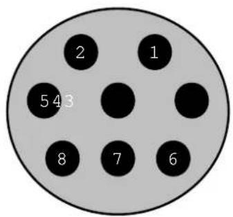
pie
| Category | Value | |---|---| | 1 | 1 | | 2 | 2 | | 3 | 543 | | 4 | 43 | | 5 | 8 | | 6 | 7 | | 7 | 6 |DIN 8 PIN MALE
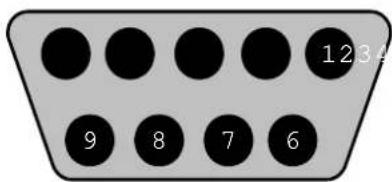
DSUB 9 PIN FEMALE
| DIN8P MALE TO DSUB9P FEMALE | ||
| PIN NAME DIN 8 PIN MALE DSUB 9 PIN FEMALE | ||
| RTS | 1 | 8 |
| CTS | 2 | 7 |
| TXD | 3 | 2 |
| GND | 4 | 5 |
| RXD | 5 | 3 |
| DTR | 6 | 6 |
| DCD | 7 | 4 |
| RI | 8 | 9 |
| NC | 1 | |
PIN Function
RTS : Return to send
GND : Ground
CTS : Clear to send
Your internet Service Provider (ISP) provides you at least one IP address which you use to connect to the Internet. The address you get may be static, meaning it never changes, or dynamic, meaning it's likely to change periodically. Just how often it changes depends on your ISP. A dynamic IP address complicates remote access since you may not know what your current WAN IP address is when you want to access your network over the Internet. The solution to the dynamic IP address problem comes in the form of a dynamic DNS service.
The Internet uses DNSs to lookup domain names and translates them into IP addresses. Domain names, such as www.intellinet-network.com, are easy to remember aliases for IP addresses. A dynamic DNS service is unique because it provides a means of updating your IP address so that your listing will remain current when your IP address changes. There are several excellent DDNS services available on the Internet, and best of all they're free. Two excellent DDNS services are www.ods.org (ODS) and www.DynDNS.org. You'll need to register with the service and set up the domain name of your choice to begin using it. Please refer the home page of the service for detailed instructions.
A DDNS service works by uploading your WAN IP address to its servers periodically, your gateway-router may support DDNS directly, in which case you can enter your DDNS account information into your router, and it will update the DDNS servers automatically when your IP address changes. Please consult your router's documentation for more information. If your router does not support DDNS, you can run a small client utility on any PC on your network, which will perform the updating. The client utility is usually provided for free by the service. Check the service's web page for further information, terms and conditions.
WIRELESS NETWORK IP CAMERA User's Guide
How to use ODS DDNS service
1. Access ODS home page (www.ods.org).

- To register your ID, select REGISTER and then register your ID/ password. After that you just log in with registered ID/password.
3. After you log in, you will see the following page.

WIRELESS NETWORK IP CAMERA User's Guide
If you want to use normal DDNS service among many services, you should fill in the blanks in the circled box and then click "Add Host."
① Host: write the name you want.
② Domain: Select the domain you want (i.E. sphere-web.com)
③ Type: Select ‘A’ (‘A’ is normal)
④ Target: Write initial IP of equipment but just write any IP address that is in the form of
“XXX.XXX.XXX.XXX”
⑤ TTL Priority: DO NOT select. This is an option.
If you want to select "intellinet.sphere-web.com.org" for domain name, write 'intellinet' in Host item and then select sphere-web.com for domain. Otherwise, please refer to the premium service.
NOTE
After completing the setup, you should set DDNS registration for the Wireless Network IP Camera
Example Configuration:
Your ODS Username: intellinet
Your ODS Password: 550703
Your ODS Domain Name: cam.sphere-web.com
DDNS Registration:
DDNS Server (max 30 characters):
ID (max 10 characters):
Password (max 10 characters):
Host Name (max 30 characters):

DDNS manual update
Status:
enable
○ disable
www.ods.org
intellinet
A
cam.sphere-web.com
submit
cancel
WIRELESS NETWORK IP CAMERA User's Guide
How to use DynDNS DDNS server
1. Access the Dyndns home page (www.dyndns.org).
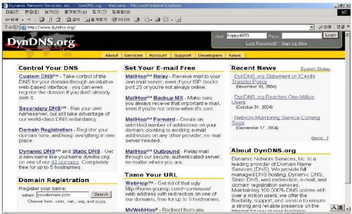
2. If you didn't register your ID, click "Sign Up Now" and then register your ID.
Otherwise, login with registered ID.

WIRELESS NETWORK IP CAMERA User's Guide
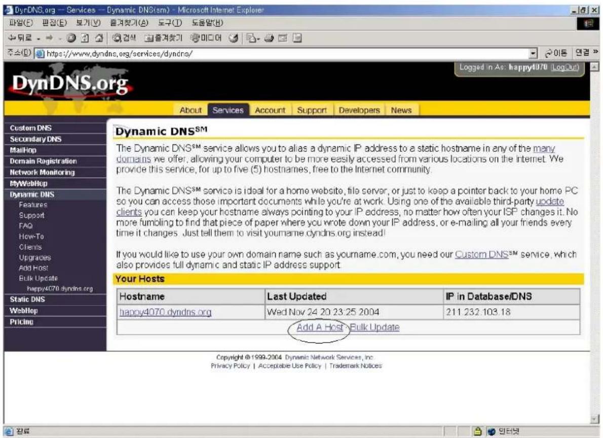
- Click "Add Host", and then go to the next page.

WIRELESS NETWORK IP CAMERA User's Guide
-
Enter the domain name you want and leave other items unchanged, and then Click "Add Host" button to register. If you want to know details of any field, please refer to FAQ for each home page.
-
You will see this confirmation page.
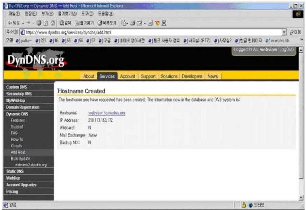
NOTE
After completing DynDNS setting, you should set DDNS registration for the Wireless Network IP Camera
DDNS Registration:
DDNS Server (max 30 characters):
ID (max 10 characters):
Password (max 10 characters):
Host Name (max 30 characters):
DDNS manual update
Status:

enable

disable
| www.dyndns.org |
| intellinet |
| xxxxxx |
| cam.dyndns.org |
submit
cancel
WIRELESS NETWORK IP CAMERA User's Guide
DDNS registration for the Wireless Network IP Camera
- After you set ODS or DynDNS successfully, you should move to administration -> network configuration.

- In DDNS Registration, select DDNS server (ODS or Dyndns) you want.
Enter ID/password that you registered and fill domain name that you set in each home page. (ex: intelligent.ods.org)
■ Before setting DDNS, you should register ID/password and domain name in ODS or Dyndns DDNS service.
- If registration is finished successfully, you will see "Registration Success." Now, you can connect to the Wireless Network IP Camera by a domain name that you registered.
WIRELESS NETWORK IP CAMERA User's Guide
I. High-Speed Solutions
This information is to help you access high-speed Internet services, such as xDSL, or a cable modem connection. However, since some high-speed Internet services may provide only one external IP address that may not be static,, there are several practical issues to consider.
AVAILABLE IP ADDRESS
An ISP (Internet Service Provider) ideally will provide you with several static IP addresses – in which case you can assign any one of these to your Wireless Network IP Camera to make it fully accessible over the Internet. However, if your service provider supplies you with only one IP address, which is often the case, this IP number is normally assigned to your PC,-leaving no connection available for your Wireless Network IP Camera.
What can you do if your ISP is unable to provide you with an IP number?
There are a number of other options to consider, including:
NAT BOX
Short for Network Address Translator, NAT is an Internet standard that allows a local-area network (LAN) to use one set of IP addresses for internal traffic and a second set of addresses for external traffic. A NAT box located where your LAN meets the Internet will handle all of the necessary IP address translations and provides:
- Internal IP addresses that are unique to your network – with no possibility of conflict with IP Addresses used by other companies and organizations.
● The possibility of combining multiple ISDN connections into a single Internet connection. - An effective firewall for hiding internal IP addresses.
NAT Feature in Windows 2000
Utilize the NAT feature in Windows 2000 to allow multiple Ethernet cards in your PC, and you can then use one of port for the Internet and the other for your internal network. With this solution, you can let your Wireless Network IP Camera upload image streams to an external Web Server that is maintained and located with your ISP.
WIRELESS NETWORK IP CAMERA User's Guide
ROUTERS AND FIREWALLS
Another solution is to use one of several small routers/firewalls currently available on the market. These provide the necessary NAT functionality and allow complete independence for your PC, which can be switched off or rebooted without affecting the image transmission from your Wireless Network IP Camera.
WINGATE SERVER SOFTWARE
Running on a single Windows 95/98/2000 or NT computer, this software allows multiple users simultaneous access to the Internet through a LAN or higher-speed line, such as xDSL or cable modem connection; and effectively shares a single Internet connection with almost any type of client computer running TCP/IP.
For more advanced users, the WinGate 3.0 Standard and Pro versions also allow the administrator to change the IP bindings so that external requests may be routed specifically to your Wireless Network IP Camera – running behind the WinGate software.
NOTE
NAT, or Network Address Translator (Virtual LAN): A hardware device currently being developed and used to extend the Internet addresses already in use. NAT has been suggested as an alternative to adopting IPv6 (IPng). It allows duplicate IP addresses to be used within a corporation and unique addresses outside. It is defined in RFC 1631.
WIRELESS NETWORK IP CAMERA User's Guide
J. Reinstating the Factory Default Settings
This information explains how to set the default settings in the Wireless Network IP Camera. In certain circumstances it may become necessary to restart or reinstate the Factory Default settings for your Wireless Network IP Camera: This is performed by pressing the Reset Button, or using the Hyper Terminal Setting. Follow these instructions to reinstate the product factory default settings
By Pressing Reset Button
① Using a paper clip or any sharp pin, press the reset button on the backside of Wireless Network IP Camera.
② Switch off the Wireless Network IP Camera by disconnecting the power cable.
③ Press and keep the Reset Button pressed, and then reconnect the power supply cable. Keep the Reset Button pressed until the Operating Status LED (Green) blinks three times. (Note that this may take up to 10\~15 seconds), then release the button.

By Using the Web Browser (System Configuration Page)
You can restore the factory default values in the Administrator Menu, System Configuration, Click on RESTORE DEFAULTS. See image below:
Reboot (Restart) Network IP Camera:
No Settings will get lost.
Restore Factory default Values:
Warning: All Settings will get lost!
Reboot
Restore Defaults
WIRELESS NETWORK IP CAMERA User's Guide
By Using Hyper Terminal (Advanced Users only)
① Execute Hyper Terminal as described in Chapter “4.3.1 Configuring Hyper Terminal”
② Supply the power to the Wireless Network IP Camera.
③ After a while, the count down starts with the message
"Press 'p' key to stop auto-boot or Load-Default-Button under the NetCam for 3 seconds..."
.At this time, press the 'p' key. Then, [Wireless Network IP Camera Boot] prompt shows like the right side image.
![WebView Boot(ENC-001B) Copyright 2000 MicroWeb Co., Ltd. Bootrom Version : B0030006 Firmware Version : F0030044 Creation date: Aug 25 2001, 10:12:41 Press 'p' key to stop auto-boot or Load-Default-Button under the NetCam for 3 seconds ... p2 [WebView Boot]:](/content/2026/06/1260183/images/760fad92e9494a850a6ec3fc636d785b2e33bb5dfc199fe2045a424aaf77bb59.jpg)
④ When you enter 'w', Administrator ID & password reset as factory default 'admin.'
NOTE
Reinstating the original default settings will cause all parameters (Including IP address) to reset.
Factory default setting
Administrator ID: admin
Administrator Password: admin
Guest ID: guest
Guest Password: guest
IP Address: 192.168.1.221
Subnet Mask Address: 255.255.255.0
Gateway Address: 192.168.1.1
Server IP Address: 192.168.1.200
Compression Rate: Level 1
Image Size: QVGA
WIRELESS NETWORK IP CAMERA User's Guide
K. Glossary of Terms
Active-X - A control (or set of rules) used by a browser. Active-X controls are often downloaded and installed automatically as required.
ARP – Address Resolution Protocol. A method for finding a host's Ethernet address from its Internet address. The sender broadcasts an ARP packet containing the Internet address of another host and waits for it (or some other host) to send back its Ethernet address. Each host maintains a cache of address translations to reduce delay and loading. ARP allows the Internet address to be independent of the Ethernet address but it only works if all hosts support it. The ARP command can be used to set the IP addresses for your product.
CGI – A standard for running external programs from a World-Wide Web HTTP server. CGI specifies how to pass arguments to the executing program as part of the HTTP request. It also defines a set of environment variables. Commonly, the program will generate some HTML which will be passed back to the browser, but it can also request URL redirection. Also, a set of rules (or a program) that allows a Web Server to communications with other programs.
DSL –Digital Subscriber Loop, A family of digital telecommunications protocols designed to allow high-speed data communication over the existing copper telephone lines between end-users and telephone companies.
DHCP – A protocol that provides a means to dynamically allocate IP addresses to computers on a local area network. The system administrator assigns a range of IP addresses to DHCP and each client computer on the LAN has its TCP/IP software configured to request an IP address from the DHCP server. The request and grant process uses a lease concept with a controllable time period.
Ethernet –A widely used networking standard.
Firewall -A virtual barrier between a LAN (Local Area Network) and other networks, e.g., the Internet.
Frame Grabber Card - Plug-in hardware for "grabbing" images.
FTP – A client-server protocol that allows a user on one computer to transfer files to and from another computer over a TCP/IP network. Also the client program the user executes to transfer files. It is defined in STD 9, RFC 959.
WIRELESS NETWORK IP CAMERA User's Guide
HTML – A markup language used to structure text and multimedia documents and to set up hypertext links between documents, used extensively on the World Wide Web.
HTTP – A protocol used to request and transmit files, especially web pages and webpage components, over the Internet or other computer network.
Intranet - A privately maintained computer network that can be accessed only by authorized persons, especially members or employees of the organization that owns it.
IP (Internet Protocol) -. The network layer for the TCP/IP protocol suite widely used on Ethernet networks, defined in STD 5, RFC 791. IP is a connectionless, best-effort packet switching protocol. It provides packet routing, fragmentation and re-assembly through the data link layer.
IP Number (address) - A unique number used by a computer on the network to allow it to be identified and found.
JPEG - A standard image format, used widely for photographs. Also known as JPG.
LAN (Local Area Network) -. A data communications network which is geographically limited (typically to a 1 km radius), allowing easy interconnection of terminals, microprocessors and computers within adjacent buildings. Ethernet and FDDI are examples of standard LANs.
PING - A protocol that sends a message to another computer and waits for acknowledgment, often used to check if another computer on a network is reachable.
PPP (Point-to-Point Protocol) - A method allowing one computer to connect to another, usually via a modem over a phone line.
Protocol - A set of formal rules describing how to transmit data, especially across a network. Low-level protocols define the electrical and physical standards to be observed, bit- and byte-ordering and the transmission and error detection and correction of the bit stream. High-level protocols deal with the data formatting, including the syntax of messages, the terminal to computer dialogue, character sets, sequencing of messages etc.
SMTP – Simple Mail Transfer Protocol
WIRELESS NETWORK IP CAMERA User's Guide
TCP/IP (Transmission Control Protocol/Internet Protocol) –. The wide-area-networking protocol that makes the Internet work. TCP/IP is used on many networks, including the Internet. TCP keeps track of the individual packets of information and IP contains the rules for how the packets are actually sent and received.
URL (Uniform Resource Locator) – An “address” on the network.
WAN (Wide-Area-Network) – A communications network that uses such devices as telephone lines, satellite dishes, or radio waves to span a larger geographic area than can be covered by a LAN.
Wizard – A program designed specifically to guide the user through a procedure. Typically used for installation and configuration. Installshield Wizard is required to download Active-X manually.
WIRELESS NETWORK IP CAMERA User's Guide
Limited Lifetime Warranty
* This INTELLINET ACTIVE NETWORKING® product is covered by the following warranty. * This warranty applies to the original purchaser only. This warranty covers defects in material and workmanship for the life of the original purchaser, for as long as the product is owned by the original purchaser. Implied warranties end when the original purchaser no longer owns the product; this limitation includes the implied warranty of merchantability. Some states or countries do not allow limitations on how long an implied warranty lasts, so the above limitation may not apply to you. * If this product fails during the warranty period because of a defect in material or workmanship, we will repair or replace the product, at our option. Repair parts may be remanufactured or refurbished. * This warranty does not cover damaged caused by: improper installation; improper repairs, servicing, or alterations; use of supplies or parts that do not meet our specifications; unauthorized modifications; failure to follow instructions; normal wear and tear; natural disasters and accidents, including fire, water, lightning, and other acts of nature; anything that is not a defect in material or workmanship. This warranty also does not cover: damage to items that occurs during shipment to us; lost data, lost time, damaged software, or loss of revenue or profits; losses covered by your insurance; shipping costs and expenses; incidental and consequential damages not listed above. Some states or countries do not allow the exclusion or limitation of incidental or consequential damages, so the above limitation or exclusion may not apply to you. * How to get warranty service: Keep your original receipt or other proof of purchase. Notify us within one week of the occurrence. Provide your name, your address, the serial number of the product, a description of the problem, and your original sales slip or invoice. If requested by us, ship to us the damaged product.
For more information or to file a warranty claim, visit www.intellinet-network.com. This warranty gives you specific legal rights, and you may also have other rights depending on your state or country.
IC INTRACOM
World Headquarters
550 Commerce Boulevard
Oldsmar, FL 34677
+1-813-855-0550
www.intellinet-network.com
Copyright 2005



- Wireless Network IP Camera
- WIRELESS NETWORK IP CAMERA User's Guide
- FCC Compliance Statement
- Important Notice
- TABLE OF CONTENTS
- PRODUCT OVERVIEW 5
- PHYSICAL DESCRIPTION 9
- INSTALLATIONSUMMARY 12
- ASSIGNING IPADDRESS & ACCESSING NETWORK IP CAMERA HOME PAGE 13
- ADJUSTING THE CAMERA LENS 29
- CONFIGURING ADMINISTRATION TOOLS 31
- PRODUCT OVERVIEW
- About the Wireless Network IP Camera
- Main Features and Benefits
- Convenient Operation
- Open Standards
- Wired and Wireless Network Support
- Simple Administration
- External Devices
- Security
- Compression and Performance
- Broad Range of Applications
- Free Application Software \*
- System Requirements
- PHYSICAL DESCRIPTION
- Contents
- Top view and Description
- NOTE
- Rear View and Description
- IMPORTANT
- INSTALLATION SUMMARY
- ASSIGNING IP ADDRESS & ACCESSING THE WIRELESS NETWORK IP CAMERA HOME PAGE
- Assigning an IP Address
- • Network IP Address:
- • MAC (Media Access Control) Address (Ethernet)
- Assigning an IP Address Using IP Installer (recommended)
- Connecting the Wireless Network IP Camera to a PC
- Using IP Installer
- Assigning IP Address by using Hyper Terminal (Advanced Users only)
- Configuring Hyper Terminal
- Assigning IP Address
- Follow these steps to assign an IP address using Hyper Terminal
- Accessing the Wireless Network IP Camera Home Page
- Starting Web Browser
- Login Page
- ID and Password
- Behind Firewall
- Active-X for MS Explorer Users
- Active-X Manual Installation
- 4) Java Applet for Windows, Macintosh or Unix System user.
- Macintosh and Unix/Linux Systems
- Wireless Network IP Camera Home Page
- Connected Client
- Administrator Menu
- Logout
- SAVE, STOP SAVE, SNAP SHOT, SHOW ONLY IMAGE
- ② SNAP SHOT
- ③ SHOW ONLY IMAGE
- Frame Rate
- Expansion
- Camera Name
- Location
- ADJUSTING THE CAMERA LENS
- Adjusting the Focus
- Replacing the Lens
- CONFIGURING ADMINISTRATION TOOLS
- Administrator Menu Overview
- CAUTION
- Image Configuration
- Compression rate
- Image Size
- Vertical Flip
- Horizontal Flip
- Display Time/Date Stamp
- Brightness Mode, Brightness
- Contrast
- Hue
- Saturation
- Sharpness
- Exposure Mode
- Exposure
- Back Light
- Further Reduce Exposure Time
- Indoor/Outdoor
- Light Frequency
- Submit
- Cancel
- Load Default Values
- Network Configuration
- Set IP Address, Subnet Mask, and Gateway Address.
- To set DHCP, you may select 'using DHCP'.
- Send IP Address to E-mail
- Server Port Number
- Image Transfer Port Number
- Ugrade Port Number
- PTZ port number (not useable in Wireless Camera)
- ETSP port number
- 1st, 2nd DNS Server Address
- DNS (Domain Name System)
- SMTP server
- Use SMTP Authentication
- DDNS Registration
- ID, Password
- Host Name
- DDNS Manual Update
- Status
- Wireless Configuration
- Wireless Setup
- Security Settings:
- Please note:
- Infrastructure Mode:
- Ad-hoc Mode:
- SSID (service set identifier):
- User Configuration
- User Account (max. 10 characters)
- Password (max. 10 characters)
- Frame Rate
- Access Rights
- Event Trigger Configuration
- Trigger Condition
- Image Capture Option
- Image capture option limitation
- Trigger Output
- FTP RENAME ENABLE:
- Time Configuration
- Synchronized with NTP server
- Set manually
- Enable Daylight Savings
- System Configuration
- Camera name
- Camera location
- Supply voltage to output port option
- Direct public access to image via HTTP
- Image file name (maximum length 10 characters)
- System information
- Reboot
- Restore Defaults
- APPENDIX
- Technical Specifications
- Image
- Network
- Image Sensor
- Lens specification
- Hardware
- I/O Connector
- Installation
- Approvals
- Operating Temperature
- Others
- Frequently Asked Question (FAQ)
- What is a Network IP camera?
- Are all Network IP cameras the same?
- Why Choose a Network IP Camera over a Web Camera?
- What is the advantage of the embedded OS?
- Do I need a public fixed IP address for each camera?
- Can I use the camera outside?
- What additional software is required?
- How does the built-in motion detection work?
- What is the maximum length Ethernet cable I can use?
- What is Power-over-Ethernet (PoE)?
- Can Network IP Cameras use different lenses?
- What image sizes can be viewed from Network IP Cameras?
- Can I view a Network IP Camera from my PDA?
- Trouble Shooting
- PINGing your IP Address
- Utilizing IP Addresses on Local Area Network
- Introduction
- IP Construction and Network Class
- IP Construction
- Network Class
- C Class Network
- Features of Addresses
- Network Configuration
- Updating Firmware
- Identify the Version of Firmware
- Download New Firmware
- Install New Firmware
- The I/O Connector
- 1-2 PIN
- 3-4 PIN
- 5-6 PIN
- RS 232 CABLE
- The Serial Connector
- PIN Function
- How to use ODS DDNS service
- Access ODS home page (www.ods.org).
- After you log in, you will see the following page.
- How to use DynDNS DDNS server
- Access the Dyndns home page (www.dyndns.org).
- If you didn't register your ID, click "Sign Up Now" and then register your ID.
- DDNS registration for the Wireless Network IP Camera
- High-Speed Solutions
- AVAILABLE IP ADDRESS
- NAT BOX
- NAT Feature in Windows 2000
- ROUTERS AND FIREWALLS
- WINGATE SERVER SOFTWARE
- Reinstating the Factory Default Settings
- By Pressing Reset Button
- By Using the Web Browser (System Configuration Page)
- By Using Hyper Terminal (Advanced Users only)
- Factory default setting
- Glossary of Terms
- Limited Lifetime Warranty
Brand : Intellinet
Model : Wireless Network IP Camera 550703
Category : Surveillance Camera