
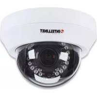
SOHO Network Camera 503365 - Surveillance Camera Intellinet - Free user manual and instructions
Find the device manual for free SOHO Network Camera 503365 Intellinet in PDF.


| Product Type | Surveillance Camera |
| Brand | Intellinet |
| Model | SOHO Network Camera 503365 |
| Dimensions | 110 x 43 x 30 mm (4.3 x 1.7 x 1.18 in) |
| Weight | 90.7 g (3.2 oz) |
| Power Supply | 5 V DC, 1.0 A |
| Image Sensor | Micron MI-360 300,000 pixels CMOS |
| Lens Aperture | F = 1.8 |
| Focus | Manual |
| Video Resolution | Up to 640 x 480 (VGA) |
| Image Compression | Motion-JPEG |
| Network Interface | RJ-45 10/100 Mbps Ethernet |
| LED Indicators | Monitoring (green), Ready (amber) |
| Operating Temperature | 10 - 45°C |
| Operating Humidity | 10 - 90% non-condensing |
| Compliance | FCC, CE, C-Tick, VCCI |
| Supported OS | Windows 98SE, Me, NT, 2000, XP, Server 2003 |
| Browser Requirement | Internet Explorer 6.x+ with ActiveX |
| Included Accessories | Power adapter, network cable (3 ft), mounting bracket, CD with software/manual |
| Video Port (Default) | 4321 |
| Web Port (Default) | 80 |
| Simultaneous View | Up to 4 cameras via Viewer utility |
| Recording | Manual and scheduled recording to AVI files |
| Snapshot | Yes, via email or save to disk |
| Firmware Upgradeable | Yes |
Frequently Asked Questions - SOHO Network Camera 503365 Intellinet
User questions about SOHO Network Camera 503365 Intellinet
0 question about this device. Answer the ones you know or ask your own.
Ask a new question about this device
Download the instructions for your Surveillance Camera in PDF format for free! Find your manual SOHO Network Camera 503365 - Intellinet and take your electronic device back in hand. On this page are published all the documents necessary for the use of your device. SOHO Network Camera 503365 by Intellinet.
USER MANUAL SOHO Network Camera 503365 Intellinet
natural_image
Exterior view of a metallic INTELLINET security camera with mounting base (no visible text or symbols beyond branding)
INTELLINET
NETWORK SOLUTIONS
BRINGING NETWORKS TO LIFE
4.1 LED and Focusing 3
4.2 Camera Ports 4
4.3 Installation Procedure 5
-
Software Installation 5
-
Using the Administrator Utility...... 17
6.1 General Setting 19
6.2 Detail Setting 21
6.3 Setting Wizard 30
- Using the Camera Viewer 34
7.1 Panel Introduction.... 35
7.2 Camera Buttons.... 36
7.3 Camera Status 37
7.4 Control Buttons 38
7.5 Video Recording.... 40
7.6 Change Resolution 42
7.7 View 4 Cameras Simultaneously..... 43
7.8 Viewer Utility Setting 44
7.8.1 Setting 45
7.8.2 Recording 47
7.8.3 Status 50
7.8.4 General 52
7.9 Playback 54
7.10 Rotate Video 57
- Web Connection and Setup 58
8.1. Camera Setting 60
8.2. Network Setting 62
8.3. Password Setting 65
-
Frequently Asked Questions ...... 66
-
Technical Specifications 68
Appendix A
Router/Gateway Setup for Internet Viewing ..... 70
Appendix B
Viewing via UPnP in Windows XP 72
1. INTRODUCTION
Thank you for choosing the INTELLINET NETWORK SOLUTIONS SOHO Network IP Camera. This Camera sends live video through the Internet to a web browser or camera viewer anywhere in the world! This compact, self-contained unit lets you keep an eye on your home, your kids, and your workplace — whatever is important to you.
How does the Camera do all of this? Unlike standard "web cams" that require an attached PC, the SOHO Network IP Camera can connect directly to a network. The Motion JPEG video compression produces a high quality, high-frame rate, 640 x 480 video stream.
The included Camera Viewer utility lets you record the video stream to your local hard drive, "live" or on a predetermined schedule.
Use the instructions in this User Manual to help you integrate the Camera into your network. These instructions should be all you need to get the most out of the SOHO Network IP Camera.
2. PACKAGE CONTENTS
• One SOHO Network IP Camera
• CD with software & user manual
• Camera mounting bracket & stand
- Power adapter
• Network cable (3 ft./900 mm)
If Any Of The Above Items Are Missing, Please Contact Your Supplier.
3. SYSTEM REQUIREMENTS
System requirements to access the SOHO Network IP Camera directly via the LAN port are:
• OS System: Windows 98SE, Me, NT, 2000, XP, Server 2003
• Microsoft Internet Explorer 6.x and above
• ActiveX control installation
4. HARDWARE INSTALLATION
4.1 LED AND FOCUSING
The SOHO Network IP Camera head and its focus ring allow you to modify the aim and focus of the Camera. To adjust the Camera's focus, rotate the dark focus ring.
There are two LEDs indicating the Camera status.
Monitoring: When someone is viewing the Camera, the green LED will light.
Ready: When the Camera is powered on and ready for access, the amber LED will light.

4.2 CAMERA PORTS
The Camera features two ports and a Reset button.
Power: The Power port is where you will connect the power adapter.
LAN: The LAN port is where you will connect the Ethernet network cable.
Reset: The Reset button is what you will press if you need to reset the Camera to factory default settings. Insert a paper clip into the hole. Then press the button and hold it in for five seconds.

4.3 INSTALLATION PROCEDURE
- Unpack the SOHO Network IP Camera package and verify that all the items listed in the Chapter 2 are provided.
- Connect the Camera to your network by attaching the network cable from the switch/router to the LAN port of the Camera.
- Connect the power adapter to the Camera and plug the power adapter into a power outlet. The Camera will be powered on. When the Camera is ready, the Ready LED will turn amber in color.
Note: It is highly recommended to use the power adapter shipped with the SOHO Network IP Camera, do NOT use any other power adapter from any sources.
5. SOFTWARE INSTALLATION
Follow the simple steps below to run the Install Wizard to guide you quickly through the Installation process. The following installation is implemented in Windows XP. The installation procedures in Windows 98SE/Me/2000/Server 2003 are similar.
-
Insert the CD shipped along with the SOHO Network IP Camera into your CD-ROM drive. The "Autorun.exe" program should be executed automatically. If not, run "Autorun.exe" manually from "Autorun" folder on the CD.
-
The Install Wizard will show four selections. Select the program you want to install or click "Exit" to install the program later. The following installation steps are part of "Install Administrator Utility & Camera Viewer".

- The system will start the installation procedures automatically. Click "Next" to continue installation.

- If you wish to install the software program in an alternate location, click "Change"; otherwise click "Next" to move on to the next step.
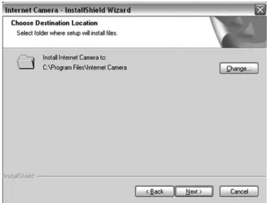
- Click "Install" to start installing the program.

- The system will install the program automatically.

- Click "Finish" to complete the software installation.

- When the installation is completed. The system will auto run the "Administrator Utility". On the Network IP Camera first page, the Cameras found in the network are listed in the left window. Choose the one you want to configure and click "Setting Wizard" to proceed.
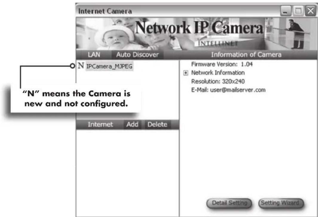
- Please enter the default password "1234" and click "OK" to log in to the IP setup page.

- The SOHO Network IP Camera operates through the network (TCP/IP Protocol). The IP address setting must be correct, or you will not be able to access the Camera. The wizard program will detect the IP address status of your network automatically and suggest a free IP address for the Camera. You can accept the suggested value or enter the value manually. If you enter the value manually, please be aware that the "Subnet Mask" must be the same for both the Camera and the PC. Click "Finish" to apply the configuration.

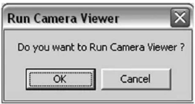
- This wizard will pop up a window to ask you if you want to run the "Camera Viewer" and see the video of the Camera immediately. Select "OK" to run "Camera Viewer".

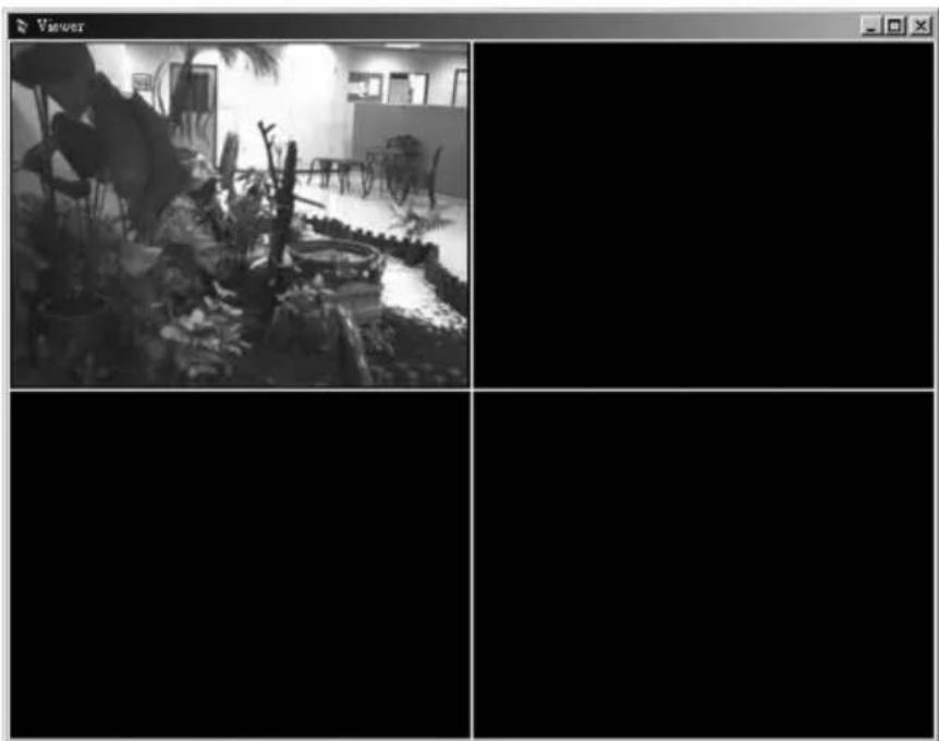
- The "Camera Viewer" will show the video automatically. Congratulations, you can now use the Camera through the network to view the video.
natural_image
Black-and-white interior scene with potted plants and furniture, no visible text or symbols6. USING THE ADMINISTRATOR UTILITY
The Administrator Utility allows users to search and setup the Cameras located within the Intranet or on the Internet. From the utility, users can view all the information of the selected Camera; furthermore, it provides a setting wizard to add the Camera to the network easily and promptly.
There are two ways to run the Administrator Utility as follows.
-
Click "Start", select "Programs\IP Camera\Admin Utility" to run the utility.
-
Click the "IP Camera Admin" icon to run the utility.

Once the utility is started, it will search all the Cameras within the network. To view additional settings, please refer to the description in the following sections.

6.1 GENERAL SETTING
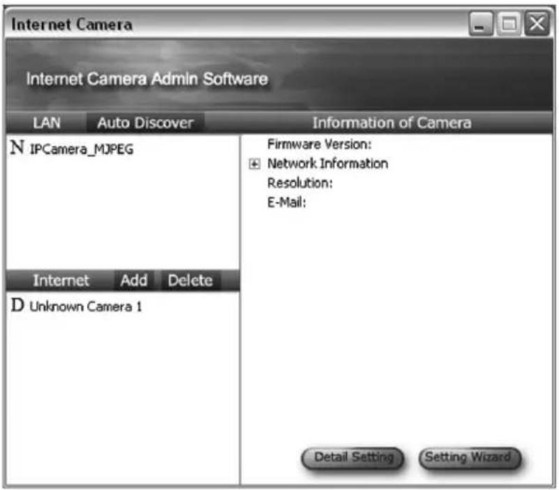
LAN
Auto Discover Clicking this button will search for the Camera within the network automatically.
Camera List The list shows the Camera name and the setup status of the Camera.
N [PCamera_M]PEG means the Camera is in the default setting.
□ IPCamera_MJPEG means the Camera is configured before.
INTERNET
Add Clicking the "Add" button will create a window for you to enter the IP Address of the Camera on the Internet.
Delete Click "Delete" to delete the Camera from the list.
Camera List The list shows the Camera name and the connect status of the Camera.
means the Camera is disconnected. Dunknot on the Internet.
means the Camera is connected. MIPCamera_MJPEG
CAMERA INFORMATION
Camera Information It displays all information of the selected camera. The information includes firmware version, network information, IP Address, UPnP setting, DDNS setting, Resolution and E-mail setting, etc.
CAMERA SETTING
Detail Setting Click "Detail Setting" for additional setting of the Camera such as IP address, Resolution, password and firmware upgrade, etc.
Setting Wizard Click "Setting Wizard" to configure the necessary setting for the Camera.
6.2 DETAIL SETTING
When you click the "Detail Setting", a screen will pop up for you to enter the "Administrator Name" and "Password". The default value is as follows:
Name: "admin"
Password: "1234"

If the name and password you enter are correct, you can start to setup the Camera.
NETWORK SETTING
| Network IP Camera Name | The default camera name is "IPCamera_MJPEG". It is recommended to change to a meaningful name for the Camera. |
| IP Address | Enter an unused IP Address within the IP address range used on your LAN. If the IP Address of your LAN is from the 192.168.2.1 to 192.168.2.254, you can set an unused IP Address from the range for the Camera, for example: 192.168.2.250. |
| Subnet Mask | The Subnet Mask field must match the subnet setting on your LAN.For example: 255.255.255.0. |
| Gateway | The Gateway is used to forward frames to destinations in a different subnet on the Internet. The Gateway setting must be the same as the gateway used by the PCs on your LAN. |
| DNS Server | DNS Server (Domain Name Server) that translates names to IP addresses. Set to the same DNS Server as the PCs on your LAN. |
| Video Port | The Video Port is used to transmit or receive the video stream through the network. The default port setting is "4321". If you want to view the video from the Camera, this port setting should be correct. |
| Web Port | This camera supports web connection and the default web port is 80. Since the web server may use port 80, you can use a different port for the Camera. If you change the web port from 80 to 8080, you must type http://192.168.2.3:8080 to connect to the Camera through a web browser. |

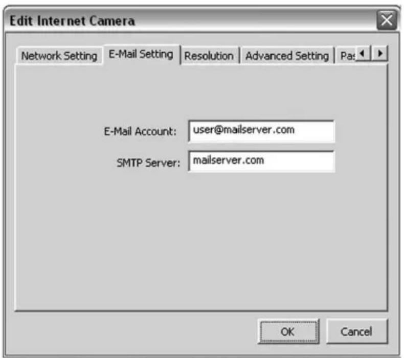
E-MAIL SETTING
E-mail Account
This Camera supports "Snap Shot" function. You can take a still image and send the picture by E-Mail. Enter the E-Mail Account for receiving the picture.
SMTP Server Enter the SMTP Server for the E-Mail account.
RESOLUTION
Resolution Select the desired video resolution format. Larger resolution requires more bandwidth. 640 x 480 is "VGA" format. 320 x 240 is "CIF" format.

ADVANCED SETTING
UPnP When the UPnP function is enabled, the Camera can be detected by UPnP
compliant systems such as Windows XP. The Camera will be displayed in the Neighborhood of Windows XP, so you can directly click the Camera to view the video through a web browser.
DDNS
Many Internet connections use a "Dynamic IP address", where the Internet IP address is allocated dynamically whenever the Internet connection is established. Internet users must know the IP Address of the Camera when they want to connect to the Camera every time. DDNS is designed to solve this problem, by allowing users to connect to your LAN using a domain name, rather than an IP address.
Enable/Disable Enable or disable DDNS function of the Camera.
Provider Several companies provide DDNS service. This Camera supports the service from DynDNS who is one of the DDNS providers.
Domain Name The domain name given by DynDNS is "registername.dyndns.com". Enter the domain name that you register the Camera with the DynDNS web site.
Account Enter the login name for the DDNS service.
Password Enter the password for the DDNS service.

PASSWORD
Current Password Enter the current password of the Camera.
New Password Enter the new password you want to use for the Camera.
New Password Retype the new password to confirm the setting.

RESOLUTION
Firmware Version Displays current firmware version.
Firmware Update Click "Firmware Update" to update new firmware for the Camera. This may take a few minutes.
Reset to Default
If you want to reset the Camera, click this button. The default settings of the Camera are as follows. Camera Name: "IPCamera_MJPEG", IP Address: "192.168.2.3", Subnet Mask: 255.255.255.0, Administrator Name: "Admin", Password: "1234", Video Port: "4321", Web Port: "80"

6.3 SETTING WIZARD
When you click the "Setting Wizard", a screen will pop up for you to enter the "Administrator Name" and "Password". The default value is as follows:
Name: "Admin"
Password: "1234"

If the name and password you enter are correct, you can start to setup the Camera.

NETWORK SETTING
| Network IP Camera Name | The default camera name is "IPCamera_MJPEG". It is recommended to change to a meaningful name for the Camera. |
| IP Address | The wizard will auto setup an available IP Address to the Camera. For example: if the IP address of the network is 192.168.2.x, the wizard will search an unused IP Address from 192.168.2.0 to 192.168.2.250 and assign the Camera an available IP Address. You are allowed to enter another IP Address to change the setting. |
| Subnet Mask | The wizard will auto search the Subnet Mask setting of the network and set the Camera in the same Subnet Mask. You can enter another Subnet Mask to change the setting. |
| Gateway The wizard will auto search the Gateway setting of the network and set the Camera to use the same Gateway. You can enter another Gateway to change the setting. | |
| DNS Server | DNS Server (Domain Name Server) that translates names to IP addresses. Set the same DNS Server as the PCs on your LAN. |
Video Port It defines the video stream port. The default value is "4321".
Cancel Click "Cancel" to stop wizard setting.
Finish Click "Finish" to complete the Camera setting.
When you finish the Camera setting, you can click "OK" to run the "Camera Viewer" immediately or click "Cancel" to run the "Camera Viewer" later.
7. USING THE CAMERA VIEWER
The Camera Viewer Utility allows users to view video from up to four cameras. It also allows users to manual/schedule record video and playback the recording file. The status of camera viewing such as frame rate, video received, and etc. are also recorded in time.
There are three ways to run the Camera Viewer Utility:
- Click "Start", select "Programs\IP Camera\Camera Viewer" to run the utility.
- Click the "IP Camera Viewer" icon to run the utility.
- Click "Setting Wizard" from Administrator Utility and follow the instructions in the utility.
7.1 PANEL INTRODUCTION
In the beginning when you start the Camera Viewer, you would see a Control Panel and a four division Viewer window.


natural_image
Four-panel black-and-white photo collage showing a clothing store interior with mannequins, baby crib, furniture, and kitchenetry (no visible text or symbols)USING THE CAMERA VIEWER
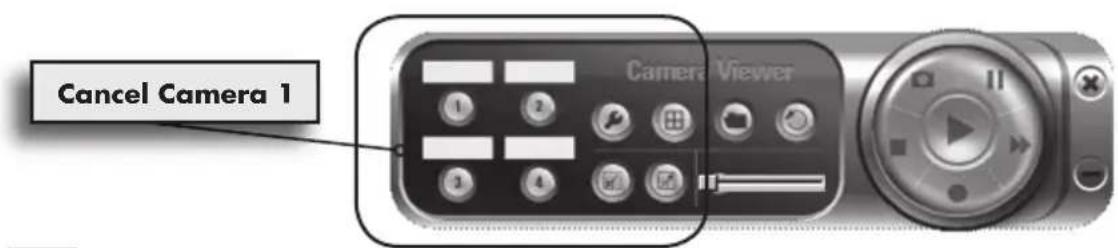
7.2 CAMERA BUTTONS
Clicking one of the four camera buttons will connect you to the Camera that you want to view and configure.

If you want to remove the Camera from the viewer, please right click the icon and select "Cancel Camera x".
7.3 CAMERA STATUS
There is a status bar showing different color to indicate the status of each SOHO Network IP Camera.

CAMERA STATUS
Yellow No camera set to connect.
Blue Camera is connected and playing the live video.
Pink Camera is not connected.
Red Camera is recording.
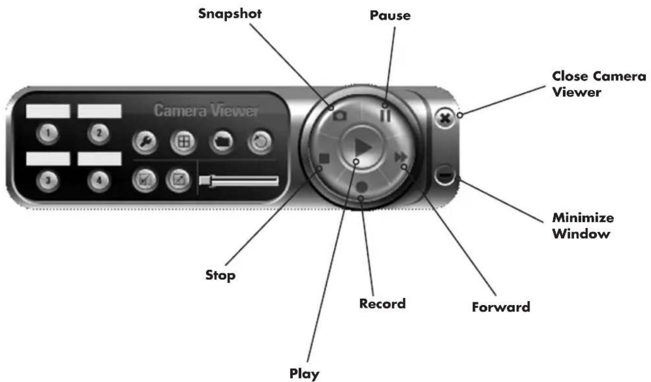
7.4 CONTROL BUTTONS
CONTROL BUTTONS
Play

The "Play" button is an intelligent play user-interface. In the normal display mode with the SOHO Network IP Camera disconnected, clicking on "Play" will connect the viewer to the Camera. In the playback mode, clicking on "Play" will play the video in the normal speed.
Stop
The "Stop" button is also an intelligent play user-interface. In the normal display mode with the Camera connected, clicking on "Stop" will disconnect the viewer from the Camera. In the playback mode, clicking "Stop" will stop playing the video.
Pause
The "Pause" button provides you a way to pause the current video display. When the displaying video is paused, click on "Play" again to resume the video display.
Forward
Clicking the "Forward" button will increase the speed of display when playing back the recording file. Clicking the button will increase the playback speed.
Snapshot

Clicking "Snapshot" will make the viewer take a snapshot of the video and save the picture as a bitmap file on the hard disk. (You can set the directory for storing these bitmap files in Section 7.8.4)
Record
By clicking on "Record" you can record video immediately.
7.5 VIDEO RECORDING
This utility allows you to record the video in AVI format files. There are two ways of video recording – Manual Recording and Schedule Recording.
Manual Recording:
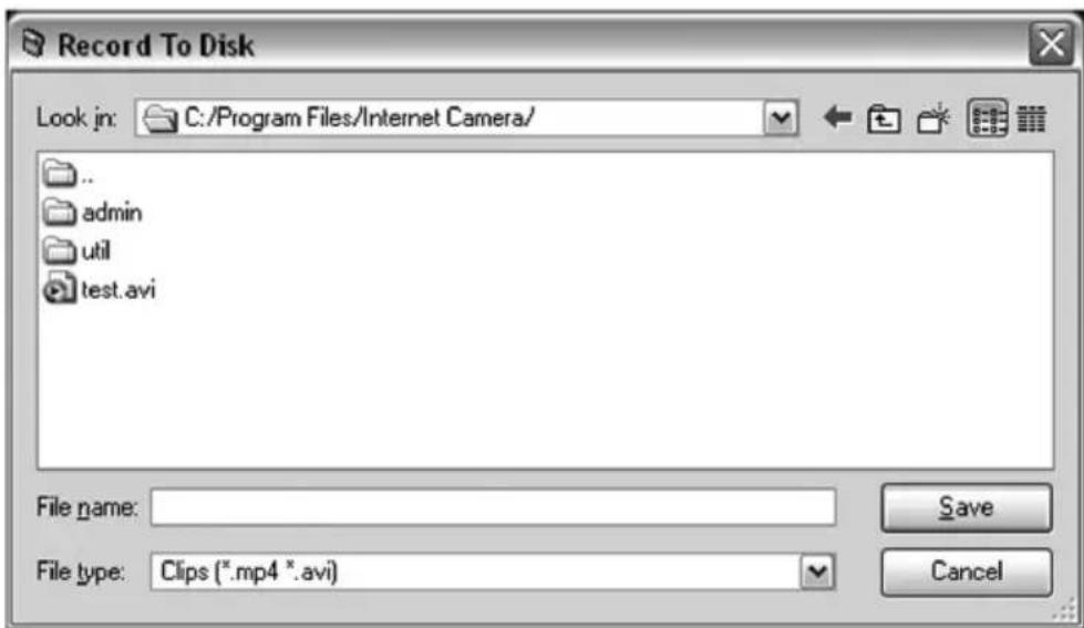
You can manually record the video stream to an assigned video file. Click "Record", and the "Record to Disk" window will pop up. Assign the path and file name and click "Save", then the viewer utility will start to record the video stream. If you want to stop recording, click "Stop".
Note: Before manual recording, you need to click the Camera button to select the SOHO Network IP Camera that you want to record first and make sure that the viewer is successfully connected to the SOHO Network IP Camera.
Schedule Recording:
You can assign a schedule and let the viewer automatically record the video stream into video files. Please refer to Section 7.8 to see how to setup a schedule for recording. The file name of the recorded video file is the start time of recording. For example, the file name "IPCamera_MJPEG_2004-10-8-23-56-40.avi" started recording at 2004/10/8 23:56:40.
7.6 CHANGE RESOLUTION
The SOHO Network IP Camera supports two levels of resolution, 640x480 (VGA) and 320x240 (CIF). You can change the resolution of each Camera by clicking the "Resolution" button.
Note: Before changing the resolution of the Camera, you have to select the Camera by clicking the "Camera" button first. If you change the resolution of a SOHO Network IP Camera, other clients that are viewing the same Camera simultaneously will also see the video with the changed resolution as well.
RESOLUTION
VGA Change the resolution to 640x480 (VGA) mode.
CIF Change the resolution to 320x240 (CIF) mode.

natural_image
Black-and-white photo of a baby's bedroom with baby crib, teddy bear, and furniture (no visible text or symbols)7.7 VIEW FOUR CAMERAS SIMULTANEOUSLY
By clicking on the four-division button to view 4 cameras simultaneously in a four-division window.


natural_image
Four-panel black-and-white photo collage showing a clothing store interior with children, baby crib, and kitchenetry (no visible text or symbols)7.8 VIEWER SETTING UTILITY
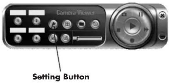
Click "Setting", in order for the setting window of the Network IP Camera to pop up.
Note: When you want to change settings such as IP Address, Video Port, etc. in the "Setting" option, you must disconnect the Network IP Camera first by clicking "Stop".
7.8.1 SETTING

7.8.1 SETTING
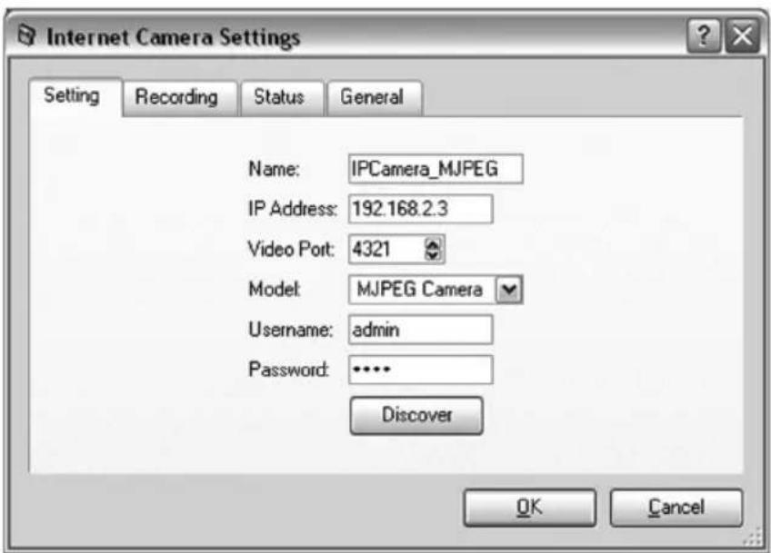
Name It is not required to fill in the Camera name in order to connect camera. It is for users to identify the Camera.
IP Address IP address/Domain name of the Camera.
Video Port The number of service port used by the Camera.
Model Select "MJPEG Camera" (This camera only supports Motion JPEG).
Username The user name for logging into the Camera. By default, the user name is "Admin".
Password The password for logging into the Network IP Camera. By default, the password is "1234".
Discover Click "Discover", and the Camera auto-discover windows will pop up. The window will show all of the discovered cameras on the LAN for you to select from.
7.8.2 RECORDING
You can setup a schedule for recording here. This utility will record the video stream in the assigned file folder according to the schedule automatically. The recorded video files are AVI format.
Note:
-
The utility will only start to record the video stream when this utility is running and is successfully connected to the Network IP Camera at the beginning of the recording schedule.
-
Do not overlap the one-time or weekly schedule setting, or the recording will fail.
![Internet Camera Settings Setting Recording Status General ✓ Cycle Recording One-Time Schedules: 2004/12/20 19:41 - 2004/12/20 19:42 New Edit Delete Weekly Schedules: [ Mon ] 19:42 - 19:43 New Edit Delete OK Cancel](/content/2026/06/1260197/images/f45f7886ff1e03a67d28c50a864cb90f2653211b11a68e0404107ca5806a3bf3.jpg)

One-Time Schedule

Weekly Schedule
7.8.2 RECORDING
Cycle Recording
Select this item to enable cycle recording. When the Cycle Recording is enabled and the storage usage has already reached the maximum reserved storage space, the utility will automatically delete the oldest recorded video file and use the space to store the newly recorded video stream.
One-Time Schedule
You can assign a range of time and the utility will automatically record the video stream only during the period of time. The default time is 2 minutes.
Weekly Schedule
You can assign the days of the week and the period of time in a day when you want to record the video stream. The utility will automatically record the video stream during the periods of time every week again and again.
New Click "New" to add a new recording schedule.
Edit
Select an existing schedule in the schedule list and click "Edit" to edit the schedule.
Delete
Select an existing schedule in the schedule list and click "Delete" to delete the schedule.
7.8.3 STATUS
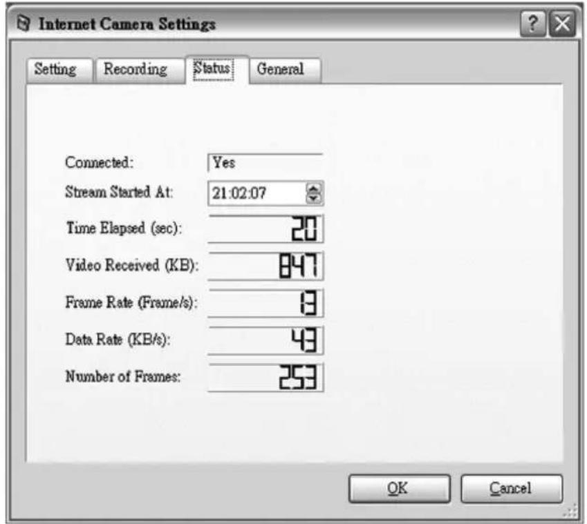
View the current status information of the connection session between the utility and the SOHO Network IP Camera.
7.8.3 STATUS
Connected Displays "Yes" when the utility is connected to the Network IP Camera and displays "No" when the utility is not connected to the Network IP Camera.
Stream Started At The beginning time of the current connection session between the utility and the Network IP Camera.
Time Elapsed The elapsed time of the current connection session between the utility and the Network IP Camera.
Video Received The total size (in Kilobytes) of video stream received during the current connection session between the utility and the Network IP Camera.
Frame Rate The frame rate (frames per second) of the current video download speed from the Network IP Camera to the utility.
Data Rate The data rate (Kilobyte per second) of the current video download speed from the Network IP Camera to the utility.
Number of Frames The total number of video frames received during the current connection session between the utility and the Network IP Camera.
7.8.4 GENERAL
Manage storage usage for the SOHO Network IP Camera here.

7.8.4 GENERAL
Snap Shot Directory
This lets you assign the directory where bitmap files will be stored when you click "Snapshot" to take pictures. The default folder is where the software program is installed, for example: "C:\Program Files\Network IP Camera".
Record Directory
This lets you assign the directory where the recorded video files will be stored. The default folder is where the software program is installed, for example: "C:\Program Files\Network IP Camera".
Free Disk Space
The current free disk space of the hard drive assigned to save recording files.
Max Recording Space
You can reserve disk space to store the recorded video and snapshot files. In the event that you run out of space, a message will pop up to notify you.
Used Disk Space The current used disk space for saving the recording file.
Max Video File Size
This let you assign a maximum size of each video file. The upper bound of this value is 2 GB per file.
7.9 PLAYBACK
Click "Open File" and a "Load File" window will pop up. Select the file that you want to play.

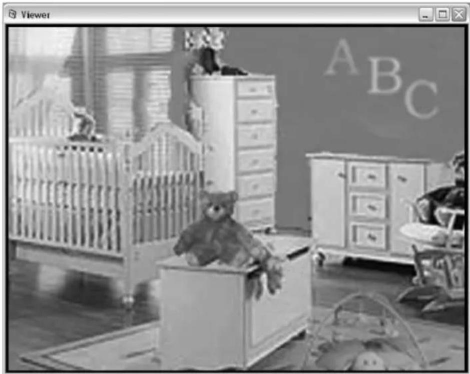
The viewer will start to play the selected video file.
natural_image
Black-and-white photo of a baby's bedroom with baby crib, teddy bear, and furniture (no visible text or symbols)USING THE CAMERA VIEWER
PLAYING CONTROL
Play When the video playback is in Stop state, click "Play" and the viewer will play
the video file from the beginning point. When the video playback is in Pause state, click "Play" and the viewer will play the video file from the current pause point. When the viewer is playing with fast speed, click "Play" to let the viewer play at the normal speed.
Pause When the recorded video is playing, click "Pause" to freeze the
playback. If you want the viewer to continue playing from the current pause point, just click "Play".
Stop When the viewer is playing, click "Stop" to stop the playback. If you want the
viewer to play again, click "Play" and the viewer will play the video file from the beginning point.
Forward

If you want the viewer to play the video file at a faster speed click "Forward" and the viewer will double the playing speed. To return to normal speed click "Play".
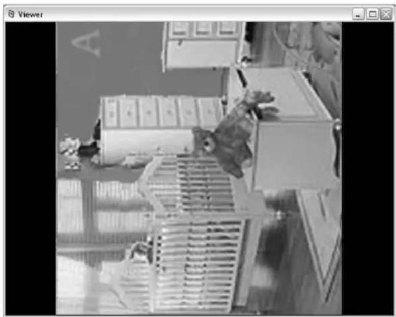
7.10 ROTATE VIDEO
The "Rotate" function lets you rotate the video frame 90° counterclockwise each time you click the "Rotate" button. With this function, you can view the live video at normal, 90°, 180° and 270° angles counterclockwise. Below is the video with 90° counterclockwise rotation.

natural_image
Black-and-white photo of a miniature office building with a model of a dog and a computer monitor, no visible text or symbols.USING THE CAMERA VIEWER
8. WEB CONNECTION AND SETUP
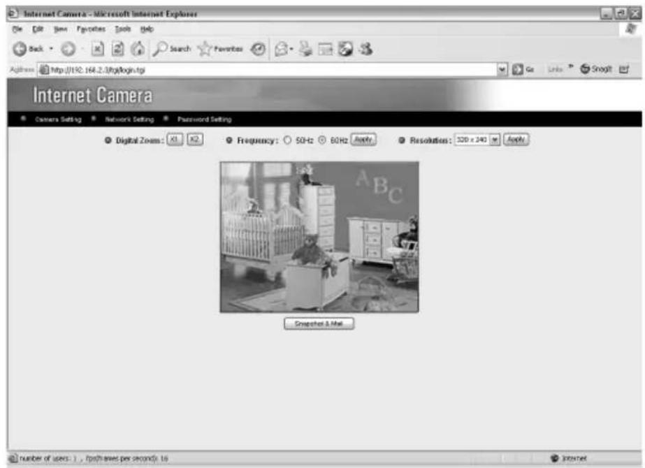
You can use the Web browser to connect to the Camera for viewing or setting. Open the web browser and enter the IP Address of the Camera to establish a connection. The default IP Address of the Camera is "192.168.2.3".
When the welcome screen appears, enter the "User Name" and "Password".
The default values are:
User Name: "admin" Password: "1234"

When the Camera is connected, the video image will be shown on the web screen directly. The menu options for the web control screen are as follows.
Camera Setting – View live video and adjust the video format from the menu.
Network Setting – Setup the Camera functions in the menu.
Password Setting – Up to four sets of user names and passwords can be set here.
8.1 CAMERA SETTING
Click "Open File" and a "Load File" window will pop up. Select the file that you want to play.
8.1 CAMERA SETTING
Digital Zoom Allows you to zoom in or zoom out.
Click "x2" and the image size in the display area will be magnified twice
the original size. In 640x480 resolution, only the central area of the screen will be magnified twice. Click "x1" and the image size in the display area will return to the original size.
Frequency Select the line frequency (50 or 60MHz) to improve the viewing quality
under fluorescent light.
Resolution Select the desired video resolution format. Larger resolution requires more
bandwidth. 640 x 480 is "VGA" format. 320 x 240 is "CIF" format. The default resolution is CIF format.
Snap Shot and Mail
If you want to capture a snapshot image from the current video, click this button. The system will immediately send the picture to the E-Mail account you set up in the "E-Mail Setting".
Apply Click "Apply" to validate "Frequency" or "Resolution" setting.
8.2 NETWORK SETTING

CHANGE ADMIN PASSWORD
Current Password Enter current password.
New Password Specify the new password you want to change to.
Confirm Password Enter the new password again for confirmation.
Apply When you finish the "Change Admin Password", click "Apply".
E-MAIL SETTING
E-mail Address Set up the E-Mail account as the receiver for snapshot pictures.
SMTP Server Specify the SMTP mail server for sending E-Mail.
Apply When you finish the "E-Mail Setting", click "Apply".
IP INFORMATION
| IP Address | Enter an unused IP Address within the IP address range used on your LAN. If the IP Address of your LAN is from the 192.168.2.0 to 192.168.2.250, you can set an unused IP Address within that range for the Camera, for example: 192.168.2.250. |
| Subnet Mask | The Subnet Mask field must match the subnet setting on your LAN. For example: 255.255.255.0. |
| Gateway | The Gateway is used to forward frames to destinations in a different subnet on the Internet. The Gateway setting must be the same as the gateway used by the PCs on your LAN. |
| DNS Server | DNS Server (Domain Name Server) translates names to IP addresses. Set the same DNS Server as the PCs on your LAN. |
| Video Port | The Video Port is used to transmit or receive the video stream through to the network. The default port setting is "4321". If you want to view the video from the Camera, this port setting should be correct. |
| Web Port | This camera supports web connection, and assigns the default web port to 80. Since the web server may use port 80, you can use a different port for the Camera. If you change the web port from 80 to 8080, you must type http://192.168.2.3:8080 to connect to the Camera through a web browser. |
Apply When you finish the "IP Information", click "Apply".
CAMERA INFORMATION
| Camera Name | The default camera name is "IPCamera_MJPEG". It is recommended to change to a meaningful name for the Camera |
Firmware Displays the current firmware version of the Camera.
Apply Once you complete filling out the "Camera Information", click "Apply".
WEB CONNECTION AND SETUP
DDNS SERVICE
Enable/Disable Enable or disable DDNS function of the Camera.
Provider Several companies provide DDNS service. This camera supports the service provided by DynDNS.
Domain Name The domain name given by DynDNS is "registername.dyndns.com". Enter the domain name that you register the Camera with the DynDNS web site.
Account Enter the login name for the DDNS service.
Password Enter the password for the DDNS service.
Apply When you finish the "DDNS Service" setting, click "Apply".
UPnP
Enable/Disable Enable or disable UPnP function of the Camera.
Apply When you finish the "UPnP" setting, click "Apply".
MAINTENANCE
Reset to Defaults
To reset the Camera to factory default, click "Apply". Then follow the instruction on the screen to complete the process. The factory defaults are as follows.
Camera Name: "IPCamera_MJPEG"
IP Address: "192.168.2.3"
Subnet Mask: 255.255.255.0
Administrator Name: "Admin", Password: "1234"
Video Port: "4321", Web Port: "80"
8.3 PASSWORD SETTING
The "Password Setting" allows the addition of up to four user accounts to view video from Camera Viewer and Web Management. These users, unlike the Administrator, are not allowed to configure the Camera.

USER 1/2/3/4
User Name Up to four sets of user names and passwords can be added. Enter the user name to be the login name to the Camera.
Password Enter up to a 4 digit password for the new user account.
Confirm Password Enter the password again to confirm the setting.
Apply Click "Apply" to add the user account.
9. FREQUENTLY ASKED QUESTIONS
Q1: What is a Network IP Camera?
A: A Network IP Camera is a standalone system connecting directly to an Ethernet or Fast Ethernet network. It is different from a conventional PC or Web Camera; the Network IP Camera is an all-in-one system with built-in CPU and web-based solution providing a low cost product that can transmit high quality video images for monitoring. A Network IP Camera can be managed remotely, accessed and controlled from any PC/Notebook over the Internet or intranet via a web browser or camera viewer.
Q2: What algorithm is used to compress the digital image?
A: The Network IP Camera utilizes JPEG image compression technology to provide high quality images. JPEG is a standard for image compression and can be applied to various web browsers and application softwares.
Q3: Can I capture or record still images from the Network IP Camera?
A: Yes, you are able to capture or record still images with the snapshot function of the Camera Viewer application supplied with the Network IP Camera CD-ROM.
Q4: What network cabling is required for the Network IP Camera?
A: The Network IP Camera uses Category 5 UTP Twisted-pair cable allowing 10 Base-T and 100 Base-T networking.
Q5: Can the Network IP Camera be setup as a PC-cam on the computer?
A: No, the Network IP Camera operates only on Ethernet and Fast Ethernet networks.
Q6: Can the Network IP Camera be connected to the network if it consists of only private IP Addresses?
A: Yes, the Network IP Camera can be connected to a LAN with private IP Addresses.
Q7: The focus on the Network IP Camera is bad, how can I correct it?
A: Adjust the Network IP Camera focus manually.
Q8: There are no images available through the web browser.
A: The Java Applet might be disabled. This has been known to occur in Windows XP SP2 and Windows Server 2003. If you are viewing the images from Internet Explorer make sure Java Applet has been enabled in the Internet Options menu (Select Advanced option and then Microsoft VM). To download the free software, please go to http://java.com/en/index.jsp.
10. TECHNICAL SPECIFICATIONS
General
• Video: Digital 24-bit Color
- Includes Easy-to-Use Viewer & Recorder Utility; View Up to 4 Cameras Simultaneously
- Provides Admin Utility & Web Browser Management
- Manual/Schedule Record, Video Playback/Stop/Forward/Pause
• Supports four additional user accounts for viewing camera
• Auto sending Snap Shot by E-mail
- Firmware Upgradeable
Network
• LAN Connector: One RJ-45 Port to Connect to 10/100 Mbps Ethernet
System Requirements
• Supports Windows 98SE/Me/NT2000/XP/2003 Server
• Microsoft Internet Explorer 6.x and above
• ActiveX control installation
Image Compression
• Video Resolution: 160 x 120, 320 x 240, 640 x 480 (VGA)
• Image Compression: Motion-JPEG Image
LEDs
• LED Indicators: Monitoring LED (Green), Ready LED (Amber)
Hardware
• CPU & DSP: RISC & JPEG
- 2 MB Flash Memory
• 16 MB SDRAM
• Power Supply: 5 V DC, 1.0 A
Image Sensor & Lens
• Maximum resolution: 640 x 480 Pixels
- Sensor: Micron MI-360 300,000 Pixels CMOS Sensor
- Exposure: Automatic
- Aperture: F = 1.8
- Lens: Manual Focus
Temperature
- Operating Temperature: 10 - 45°C
- Operating Humidity: 10 - 90 % Non-condensing
Approvals
• FCC, CE, C-Tick, VCCI
Dimensions
- 110 ~mm × 43 ~mm × 30 ~mm (4.3 × 1.7 × 1.18 in.); 3.2 oz. (90.7 g)
APPENDIX A
ROUTER/GATEWAY SETUP FOR INTERNET VIEWING
To view the SOHO Network IP Camera across the Internet, the Router/Gateway must be configured to pass incoming TCP/UDP connections from the remote PC to the Camera.
The Router/Gateway should be set for port forwarding or virtual server for the connections.
Please see the illustration below.

flowchart
graph LR
    A["Internet"] --> B["Modem"]
    A --> C["Router"]
    B --> D["PC"]
    C --> E["IP Camera 192.168.2.3"]
    F["Remoter User"] --> A
    G["Remoter User"] --> A
    H["Remoter User"] --> A
NAME PROTOCOL PORT LAN IP
Setup 1 TCP 80 192.168.2.3
Setup 2 TCP 4321 192.168.2.3
Setup 3 UDP 13364 192.168.2.3
Setup 4 UDP 15973 192.168.2.3
PORT DEFINITION
Setup 1 Web port. Configure the protocol to "TCP".
Setup 2 Video port. Configure the protocol to "TCP".
Setup 3 SOHO Network IP Camera and Administrator Utility communication. The protocol setting must be "UDP".
Setup 4 SOHO Network IP Camera and Camera Viewer Utility communication. The protocol setting must be "UDP".
VIEWING NETWORK IP CAMERA VIA WEB BROWSER
Setup 1/Setup 2 To view the video via a Web Browser, ensure the Router/Gateway has configured Setup 1 and Setup 2. If the web port is not default port "80", but changed to 8080, the remote user must enter http://203.30.212.82:8080.
VIEWING NETWORK IP CAMERA VIA CAMERA VIEWER UTILITY
Setup 2/Setup 4
To use the Camera Viewer Utility to view the Camera, please make sure the Router/Gateway has configured Setup 2 and Setup 4.
SETUP NETWORK IP CAMERA VIA ADMINISTRATOR UTILITY
Setup 3 If you want to use Administrator Utility to configure the Network IP Camera via the Internet, the Router/Gateway should configure Setup 3.
APPENDIX B
VIEWING VIA UPNP IN WINDOWS XP
When the UPnP function is enabled, the SOHO Network IP Camera can be detected by a UPnP compliant systems such as Windows XP. The camera will be displayed in the Neighborhood of Windows XP, so you can directly double click the Camera or right click the Camera and select "Invoke" to view the video through a Web browser.


Enable UPnP in Windows XP SP2
If you can't find the Camera in the Neighborhood of Windows XP SP2 or you have seen the following message when you double click the Camera, check to see if UPnP function is being blocked by the firewall. If this is the case, then please follow the steps below to enable it:

-
Go to "Start\Settings\Network Connections".
-
Right click "Local Area Connection" and select "Properties".
-
In the "Local Area Connection Properties", select "Advanced" option menu and click "Settings".

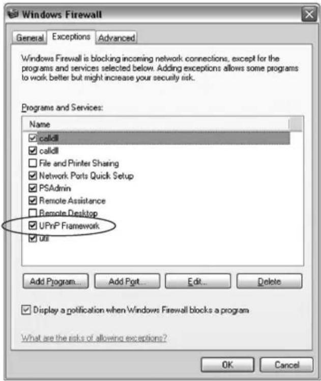
- The "Windows Firewall" screen will pop up, select "Exceptions" option menu
![Windows Firewall General Exceptions Advanced Windows Firewall is helping to protect your PC Windows Firewall helps protect your computer by preventing unauthorized users from gaining access to your computer through the Internet or a network. On [recommended] This setting blocks all outside sources from connecting to this computer, with the exception of those selected on the Exceptions tab. Don't allow exceptions Select this when you connect to public networks in less secure locations, such as airports. You will not be notified when Windows Firewall blocks programs. Selections on the Exceptions tab will be ignored. Off [not recommended] Avoid using this setting. Turning off Windows Firewall may make this computer more vulnerable to viruses and intruders. What else should I know about Windows Firewall? OK Cancel](/content/2026/06/1260197/images/ecb2c6b1e791aec9d198798a2f1e42ddfa3a307b14b9dfa6fc43218d0f3df5dd.jpg)
- Enable "UPnP Framework" from the "Programs and Services list" and click "OK".

BRINGING NETWORKS TO LIFE
www.intellinet-network.com
Are you completely satisfied with this product? Please contact your INTELLINET NETWORK SOLUTIONS™ dealer with comments or questions.
All products mentioned are trademarks or registered trademarks of their respective owners.


- INTELLINET
- INTRODUCTION
- PACKAGE CONTENTS
- SYSTEM REQUIREMENTS
- HARDWARE INSTALLATION
- LED AND FOCUSING
- CAMERA PORTS
- INSTALLATION PROCEDURE
- SOFTWARE INSTALLATION
- USING THE ADMINISTRATOR UTILITY
- GENERAL SETTING
- LAN
- INTERNET
- CAMERA INFORMATION
- CAMERA SETTING
- DETAIL SETTING
- E-MAIL SETTING
- E-mail Account
- RESOLUTION
- ADVANCED SETTING
- DDNS
- PASSWORD
- SETTING WIZARD
- NETWORK SETTING
- USING THE CAMERA VIEWER
- PANEL INTRODUCTION
- CAMERA BUTTONS
- CAMERA STATUS
- CAMERA STATUS
- CONTROL BUTTONS
- CONTROL BUTTONS
- Play
- Stop
- Pause
- Forward
- Snapshot
- Record
- VIDEO RECORDING
- Manual Recording:
- Schedule Recording:
- CHANGE RESOLUTION
- VIEW FOUR CAMERAS SIMULTANEOUSLY
- VIEWER SETTING UTILITY
- SETTING
- RECORDING
- Note:
- Cycle Recording
- One-Time Schedule
- Weekly Schedule
- Edit
- Delete
- STATUS
- GENERAL
- Snap Shot Directory
- Record Directory
- Free Disk Space
- Max Recording Space
- Max Video File Size
- PLAYBACK
- PLAYING CONTROL
- ROTATE VIDEO
- WEB CONNECTION AND SETUP
- CAMERA SETTING
- Snap Shot and Mail
- NETWORK SETTING
- CHANGE ADMIN PASSWORD
- DDNS SERVICE
- UPnP
- MAINTENANCE
- Reset to Defaults
- PASSWORD SETTING
- USER 1/2/3/4
- FREQUENTLY ASKED QUESTIONS
- Q1: What is a Network IP Camera?
- Q2: What algorithm is used to compress the digital image?
- Q3: Can I capture or record still images from the Network IP Camera?
- TECHNICAL SPECIFICATIONS
- General
- Network
- System Requirements
- Image Compression
- LEDs
- Hardware
- Image Sensor & Lens
- Temperature
- Approvals
- Dimensions
- APPENDIX A
- NAME PROTOCOL PORT LAN IP
- PORT DEFINITION
- VIEWING NETWORK IP CAMERA VIA WEB BROWSER
- VIEWING NETWORK IP CAMERA VIA CAMERA VIEWER UTILITY
- SETUP NETWORK IP CAMERA VIA ADMINISTRATOR UTILITY
- APPENDIX B
- Enable UPnP in Windows XP SP2
Brand : Intellinet
Model : SOHO Network Camera 503365
Category : Surveillance Camera