
MB-MBR - Detector BOSCH - Free user manual and instructions
Find the device manual for free MB-MBR BOSCH in PDF.


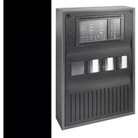
| Product Type | Distributed Panel (MBR Board) for HMB Voice Evacuation System |
| Brand | Bosch |
| Model | MB-MBR |
| Category | Detector (Component of Fire Alarm Voice Evacuation System) |
| Communication Bus | RS-485 NetCom Bus; Unshielded Twisted Pair (UTP) 18/2 AWG min; Max distance 4000 ft (120 ohms impedance); 1.024 MHz data rate |
| Speaker Circuits | 4 Class B (Style Y) expandable to 8; or 4 Class A (Style Z); 50W max per output; supervised for short/open |
| Fire Phone Circuits | Up to 16 circuits; 24 VDC @ 50 mA max per loop; supervised |
| Power Supply (AC) | 120 VAC, 60 Hz (pigtail leads) |
| Battery Backup | 24 VDC (two 12V gel cell in series); 7 to 18 Ah (EVX-25E/50E) or 24 Ah (EVX-100E) |
| Battery Charging Current | 800 mA |
| Maximum Distributed Panels per System | 250 |
| Amplifier Output Power (EVX models) | 25W, 50W, or 100W selectable (25/70 Vrms) |
| Output Protection | Power-limited, open and short circuit protected |
| Wiring Requirements | Power-limited and non power-limited separation (1/4 in. min or use FPL/FPLR/FPLP cable); Speaker zones #18 AWG min, Fire Phone #22 AWG min; conduit required for AC and battery |
| Environmental | Clean, dry environment; avoid vibration |
| Standards Compliance | NFPA 70, NFPA 72, NFPA 101, UL listed |
| Diagnostics | Power-on diagnostics, LED fault codes (1-32 flashes); green LED steady when operational |
| Microphone Disable | Automatically disables microphone if keyed continuously for 3 minutes (tamper protection) |
| Battery Maintenance | Replace both batteries every 3-5 years with same amp-hour rating |
| Testing | Annual 100% system test per NFPA 72 Chapter 7 |
| Typical Application | Voice evacuation and fire fighter communication in commercial buildings |
Frequently Asked Questions - MB-MBR BOSCH
User questions about MB-MBR BOSCH
0 question about this device. Answer the ones you know or ask your own.
Ask a new question about this device
Download the instructions for your Detector in PDF format for free! Find your manual MB-MBR - BOSCH and take your electronic device back in hand. On this page are published all the documents necessary for the use of your device. MB-MBR by BOSCH.
USER MANUAL MB-MBR BOSCH
BOSCH HMB Installation Instructions
OVERVIEW - Engineer's Specification
The BOSCH HMB system shall include one Master Panel and one or more Distributed Panels. The system shall be microprocessor based, and shall be compatible for use with contact closures from the Fire Alarm Control Panel, (FACP). The system shall have a high-speed communication bus and have the capacity for 6 channels of combined audio and data on a single pair of wires. The field wiring for the communication bus may be configured for either Style 4 or Style 7 supervision. The system shall have the capacity for Fire Fighters Phone communication. The system shall have a minimum capacity of 2048 monitor and control points.
The Master Panel shall contain an integral microphone, dual channel digital message repeater, (DMR) and digital tone generator, 120 VAC power supply, and battery charger. The system shall be modular in design, and shall be expandable such that additional system control points may be configured. The system shall include integral self-diagnostic routines that shall continually monitor system status, and shall indicate the precise type of trouble conditions should they occur in the system. A trouble condition within the system shall cause a trouble indication to be transmitted to the FACP.
Distributed panels shall provide a minimum of 4 Class "B" (Style Y) speaker circuits, expandable to eight total. Alternately, panel may be configured for 4 Class "A" (Style Z) speaker circuits. Panel will provide up to 6 simultaneous audio channels, up to 16 Fire Phone circuits. Amplifiers will contain their own power supplies, battery chargers and provide auxiliary power for other components. Speaker circuits shall be supervised for short and open circuit conditions, and shall be able to withstand transient or continuous short-circuit conditions without damage to the system.
System may be configured for General Alarm All Call operation, Alarm by Zone or Floor Above / Floor Below as required. Contact closures shall allow immediate broadcast of an alarm signal and evacuation message to the appropriate area. Non-Alarm areas may receive alert tones and messages as required or activated by the FACP.
The alarm signal/evacuation message shall be broadcast until the FACP is reset, or until emergency personnel interrupt the broadcast with a manual page.
To prevent unauthorized tampering, the voice evacuation system shall disable the microphone if the microphone is keyed continuously for 3 minutes or more. Systems that do not have this feature shall not be acceptable.
Please read this Manual completely before installing the HMB System.
INSTALLATION
Installer must insure that all wiring and devices installed in system meet the following standards:
National Electrical Code (NFPA 70)
NFPA Standard 72
Life Safety Code (NFPA 101)
Install equipment in a clean, dry environment, avoid installation where equipment could be subjected to vibration. ** Make sure all Non-Power Limited cabling is separated from Power Limited cabling.**
WIRING (Refer to wiring and terminal designation diagrams)
MASTER PANEL
- Connect Netcom Bus between all panels. Maximum distance between panels is 4000' (min 16 AWG) or 120 Ohms max. Impedance. See page 5 for wire type.
- Connect AC power to master panel and then connect batteries.
- Once power is on to the unit, connect battery wiring harness from the PWR power supply board TB-1 Red (+) / Black (-). Observe polarity. Minimum battery size is 7AHr. (Max 24 Ahr in a separate Battery cabinet) (use 2 12V batteries connected in series) *See Master panel wiring diagram on page 6. *
NOTE: Wiring for batteries and 120 VAC is Non Power-Limited. Care must be taken to insure that all Power-Limited wiring maintain a minimum spacing of 14 from any Non Power-Limited wiring. If batteries must be located in separate enclosure, provide separate conduit run for battery wiring only.
DISTRIBUTED PANELS
(Maximum number of Distributed Panels is 250 on a system)
- Speaker circuits require an End of Line resistor for supervision. Attach a "reference value" EOLR for the speaker circuits to TB9 - 1 & 2 on MBR board. This value must be placed at the end of the speaker line as well. The system is shipped from the factory with 10kOhm12 watt EOLR.
- Connect all speaker loops (UL listed devices) to TB1 - TB4 along the top edge of the MBR mother board in the Distributed panels. Fire Phone circuit connects to TB5.-TB6 on the left side of the MBR Motherboard in the Distributed panels.
-
Connect 120 VAC, 60 Hz, power to the black and white pigtail leads from transformer primary. Secure ground lead to grounding stud in cabinet located on the backplate.
-
Once all power and circuits are connected, initiate a 'Global Reset' This is done by holding the "Fault Silence" switch in the up position while the 'System Reset' switch is clicked twice. This will rerun the 'Power On Diagnostics' program. The Green LED will remain on to indicate that the HMB system is fully operational and all circuits are nominal. Observe the display during the reset, it will show how many DP in the loop.
BATTERY MAINTENANCE
Typical battery life is approximately 3-5 years depending on usage. Always replace both batteries with same amp hour ratings and of approximately the same age. Refer to the battery manufacturer's specifications for the particular battery used.
System Operation
\*\*Note\*\* ALL panels in system are pre-programmed at the factory
Alarm When an input on the MX-II FACP Interface card is pulled down to circuit common (0VDC), the Evacuation Signal and Message will be broadcast into the selected Evacuation Zone. If 'Floor-Above/Floor-Below' has been enabled, the Evacuation Zone for the floor above and the floor below the selected zone(s) will also be activated.
The floor(s) receiving the Alarm Tone/Message is displayed by a slow (2 second) flashing of the LED associated with the Evacuation Zone on the Paging Control panel.
If 'Set Alert Non Fire Floors' has been enabled in programming, all floors not broadcasting the Evacuation Signal and Message will begin broadcasting the Alert Signal and Message.
In addition, if the paging microphone is used and no Evacuation/Paging Zones have been manually selected, paging will automatically be routed to those zones that are in alarm. The Evacuation Signal will resume when paging is ended as will the Evacuation Message.
If an Evacuation/Paging Zone is selected manually, paging will take place in the selected zone, or zones, only (operation if system was designed as "dual" channel)..
Within a single Distributed Panel, and due to the nature of Dual Channel systems using one amplifier per channel, paging into an Evacuation/Paging Zone broadcasting the Alert Signal and Message will silence the other zones also broadcasting the Alert Signal and Message if there is also a zone broadcasting the Alarm Signal and Message. In other words, within a single Distributed panel only two audible signals can be broadcast at one time, either Alarm and Alert Signals, Alarm Signal and Paging or Alert Signal and Paging.
Paging When an Evacuation/Paging Zone is selected by the operator using the associated switches on the Paging Control panel, the LED(s) will indicate which zone(s) have been selected. The All-Call switch on the HMB Control panel will select all zones for paging when clicked once. A second click of the All-Call switch will deselect all zones.
The Zone Selection switches indicate which zones have been selected for paging. Broadcast of live voice messages does not take place until the Push-to-Talk switch on the microphone is pressed.
Fire Phone When a Fire Phone Handset is plugged into a Fire Phone Jack, the LED on the Zone Control panel associated with that Fire Phone zone will start flashing. A ringing signal will be heard to indicate that a handset has been jacked in. The ringing signal will cease when the Fire Phone Zone is selected.
Normally, only one Fire Phone Zone is selected at a time. Selecting another zone where a handset is jacked in will deselect the other zone(s).
HMB Control Panel Refer to Master Panel Controls and Display diagram (Page 6).
The Control Panel status indicators are 'Alarm', 'Fault' and 'Power'.
During 'Power On Diagnostics', the system is scanned for active Distributed Panels and peripherals. The Message Display indicates how many Distributed Panels have been found and all event buffers are cleared.
The 'Power' indicator is on as long as there is power available to the HMB Master Panel.
The 'Alarm' indicator will be on whenever an Evacuation Signal or Alert Signal is active.
The 'Fault' indicator will be on (blinking) whenever a fault has occurred in the HMB system. The Message display will indicate a code for the fault that has occurred. In addition, the audible fault signal will be active (beep tone) as long as the fault persists. The 'Fault Silence' switch can be used to silence the audible fault indication, but the visual indicator can only be cleared by an HMB system Reset. If the fault is cleared manually the yellow led indicator can be cleared with a single click of the reset switch.
The 'All-Call' switch will select all available Evacuation/Paging zones on the Paging/Zone Control panel when clicked. Individual paging zones may be deselected using the Paging/Zone Control switches, but a second click of the 'All-Call' switch will deselect the remainder.
The 'System Reset' switch will clear the Master Panel back to it's power on condition but will not cause the system to rerun the 'Power On Diagnostics' program (see 'Global Reset' below). After the 'System Reset' has run its course any Evacuation or Alert Signal that has been input will be reprocessed.
The 'System Reset' switch must be clicked twice within a two second interval to take effect.
A 'Global Reset' can be initiated by holding the "Fault Silence" switch in the up position while the 'System Reset' switch is clicked twice. This will rerun the 'Power On Diagnostics' program. Observe the message display during the reset. It will display +0 then the number of Distributed panels in the communication loop of the HMB system.
BOSCH HMB True Multiplex System Typical System Layout
NetComm Loop: Unshielded Twisted Pair, Single pair 18/2 or larger, Unshielded twisted pair (UTP) FPL, FPLR, FPLP run in conduit
Master Panel
Head End Control

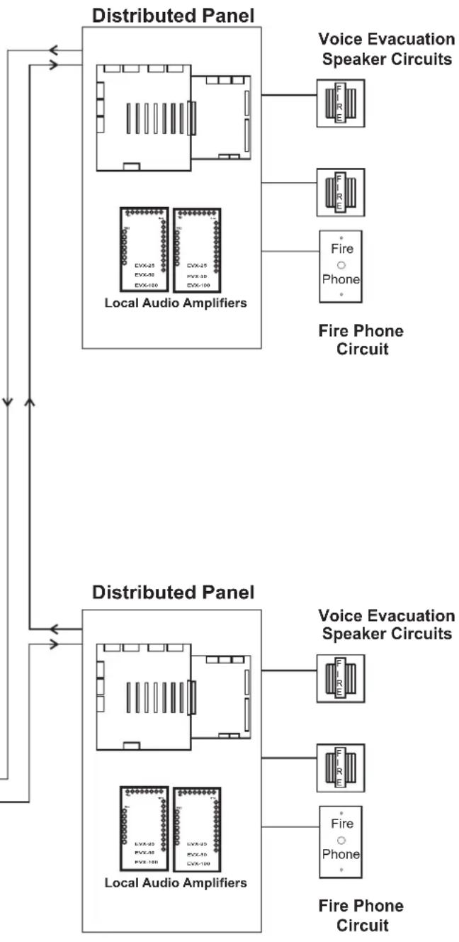
flowchart
graph TD
    A["Distribution Panel"] --> B["Local Audio Amplifiers"]
    A --> C["Local Audio Amplifiers"]
    B --> D["Fire Phone Circuit"]
    C --> E["Fire Phone Circuit"]
    D --> F["Voice Evacuation Speaker Circuits"]
    E --> G["Voice Evacuation Speaker Circuits"]
    F --> H["Fire Phone"]
    G --> I["Fire Phone"]
    style A fill:#f9f,stroke:#333
    style B fill:#ccf,stroke:#333
    style C fill:#ccf,stroke:#333
    style D fill:#cfc,stroke:#333
    style E fill:#cfc,stroke:#333
    style F fill:#fcc,stroke:#333
    style G fill:#fcc,stroke:#333
    style H fill:#cff,stroke:#333
    style I fill:#cff,stroke:#333

All wiring with exception of 120 VAC and Battery Connection is Power-Limited.
Route AC power and Battery wires to bottom-left or lower-left side Knock-out ..
*1 All Power Limited wiring must maintain a min. 1/4" separation from Non Power Limited wiring. (This requirement may be waived if Type FPL, FPLR or FPLP wire is used for Power Limited circuits)
*2 Wiring from FACP must be run in conduit. Panels must be within 20' and in the same room.
Field wiring connections:
6-32 wire clamp screw 14-18 AWG
8-32 wire clamp screw 12-18 AWG
Horizontal wire entry terminal 18-26 AWG Wire gauge determined by circuit load
Distributed Panel Wiring

EVX 25(E) / 50(E) / 100(E) TROUBLE CODES
When a unit goes into a Trouble Condition, the Yellow LED will remain on until the trouble is cleared. The Green LED will flash a Code to indicate the type of Trouble Condition. There will be a pause between repeats of the code. When multiple Trouble Conditions occur at the same time, the codes will add together.
The number of flashes and associated Trouble Condition are listed below.
Code Trouble
| 1 | Power Failure | 8 | Amplifier Trouble |
| 2 | Open Speaker Circuit | 16 | Microphone Trouble |
| 4 | Shorted Speaker Circuit | 32 | Battery Trouble |
| 6 | External Trouble / Ground Fault |
* 6 flashes typically indicates "External Trouble", such as an EVX-RM. If LED 4 is on, the 6 flash indicates a ground fault. If both a ground fault condition and an external trouble occur simultaneously, the fault codes will not combine for 12 flash.
Refer to Installation Instructions P/N B-5001 for all amplifier specifications
Field wiring connections:
6-32 wire clamp screw 14-18 AWG
8-32 wire clamp screw 12-18 AWG Horizontal wire entry terminal 18-26 AWG
Wire gauge determined by circuit load
Master Panel DCC
Connection Detail
Terminal Designation

Dist. Panel

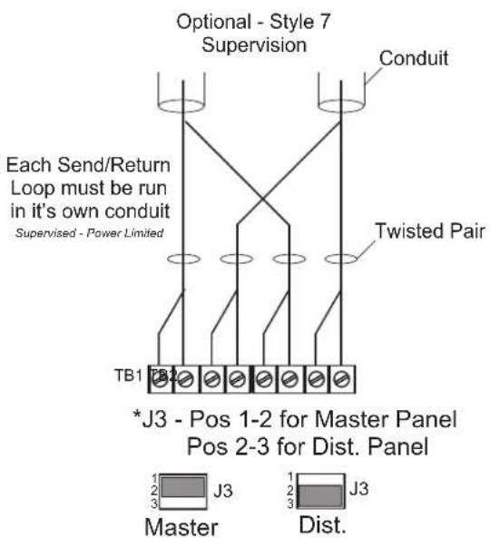
flowchart
graph TD
    A["Conduit"] --> B["Twisted Pair"]
    B --> C["Master"]
    B --> D["Dist."]
    E["TB1"] --> F["Top 2"]
    G["*J3 - Pos 1-2 for Master Panel\nPos 2-3 for Dist. Panel"] --> H["1\n2\n3"]
    I["Each Send/Return Loop must be run\nin it's own conduit\nSupervised - Power Limited"] --> J["Top 2"]
    K["Optional - Style 7 Supervision"] --> L["Top 2"]
    M["Ch conv"] --> N["Top 2"]
    O["Conv"] --> P["Top 2"]
TB1
Primary data loop
1 - Rx - (From last/previous DCC)
2 - Rx +
Secondary data loop
3 - Rx - (From last/previous DCC)
4 - Rx +
TB2
Primary data loop
1 - Tx - (To first/next DCC)
2 - Tx +
Secondary data loop
3 - Tx - (To first/next DCC)
4 - Tx +
TB3
1 - Earth (Chassis)
2 - Circuit NEG
3 - + 24 VDC @ 160 mA (Remote) 220 mA (Master)
4 - Fault (Pull Down 0V)
TB4 Not Connected
TB5 Not Connected

flowchart
graph TD
    A["To FACP Input Control (N.O. Dry Contact)"] --> B["1"]
    A --> C["2"]
    A --> D["..."]
    A --> E["7"]
    A --> F["Common NEG"]
    A --> G["+"]
    A --> H["-"]
    B --> I["TB1 TB2 Input Card MX-II"]
    C --> I
    D --> I
    E --> I
    F --> I
    G --> I
    H --> I
    I --> J["1-8 Input Control (1mA 5VDC)"]
    I --> K["9 Circuit Common (NEG)"]
    I --> L["10 FACP Bell Circuit + (Alarm)"]
    I --> M["11 FACP Bell Circuit - Polarity (10mA 24VDC)"]
    I --> N["End of Line Resistor for FACP Bell Circuit"]
    O["Wiring FACP Bell Circuit - #18 AWG. Input Control - #24 AWG. (Must be in the same room within 20 feet of panel, in conduit)"]
    P["In normal operation, FACP will supervise system by reading its EOLR. Under any Fault condition in the HMB system a contact will open resulting in a Fault on the FACP bell circuit."]

Field wiring connections:
6-32 wire clamp screw 14-18 AWG
8-32 wire clamp screw 12-18 AWG
horizontal wire entry terminal 18-26 AWG
Wire gauge determined by circuit load
jumper J1
remove before connecting batteries
PWR
TB1:
Ter. 1 & 2
battery connections
1- circuit negative
2-+24VDC
max charging current: 1A
max recommended battery
size: 18ah
TS1:
Ter. 1,2,3
+24 VDC output
1-fault report output
2-+24 VDC
3-circuit negative
TS2:
Ter. 1,2,3
28 VAC input
1,2 - 28 VAC in
3 - ground fault detect,
to chassis (optional- if unit mounted with snap track, connection is necessary. If metal standoff used in lower left corner, connection is not necessary)
MBR
Connection Detail
Terminal Designation
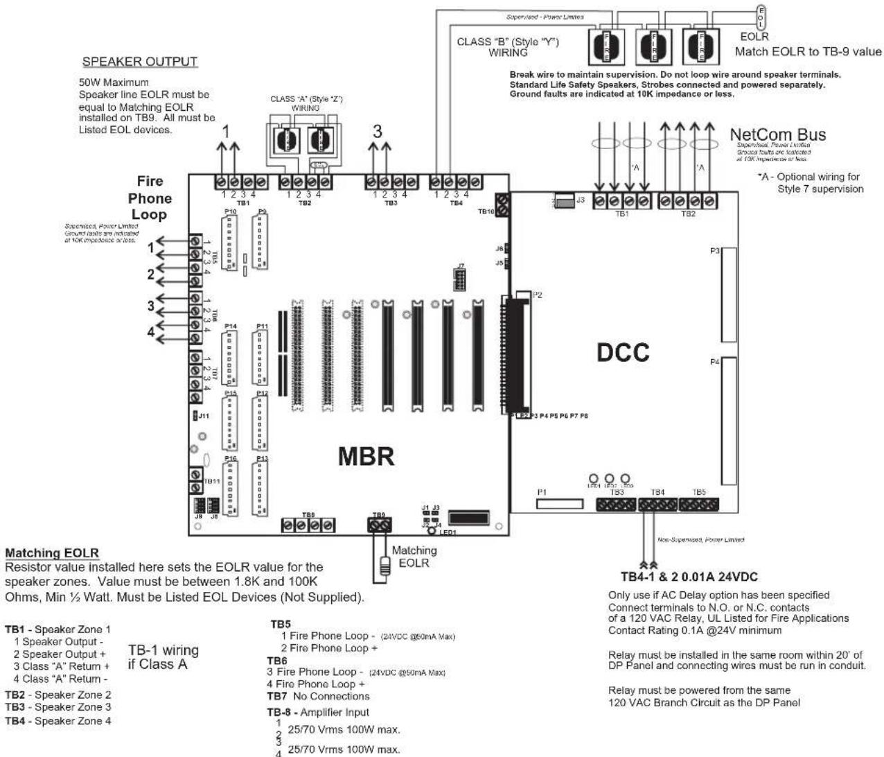
J9 - right 2 rows "shorted" class B speaker circuits
left 2 rows "shorted" class A speaker circuits
J8 - right 2 rows "shorted" Factory setting
Wiring
Speaker Zones - #18 AWG min.
Fire Phone - #22 AWG min.
(Max. Line Res. = 50 Ohms)
Fire Phone Loop - Connection Detail
Fire Phone Loop---Supervised, Power Limited
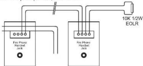
* Maximum line resistance = 50 Ohms
Field wiring connections:
6-32 wire clamp screw 14-18 AWG
8-32 wire clamp screw 12-18 AWG
Horizontal wire entry terminal 18-26 AWG
Wire gauge determined by circuit load
HMB Specifications
Communications Bus: The communications bus conforms to the RS-485 standard and requires the use of UTP- cable for 1M Baud data rates. Wiring must be run in conduit in a daisy chain from the Master Panel to the first Dist. Panel, from each Dist. Panel to the next Dist. Panel and from the last Dist. Panel back to the Master Panel. When style 7 wiring is used, a separate conduit for each bus must be used.
Voltage: 5V peak-to-peak max.
Current: 50mA max.
Impedance: 120 Ohms
(max. imp. between panels)
Frequency: 1.024MHz
Power Requirements: Power supplied to the DCC module is routed to any attached peripherals. These peripherals in turn determine whether the DCC is part of a Master Panel or a Dist. Panel. Amplifier modules in Dist. Panel are powered separately and provide 24 VDC power to the panel.
Master Panel
Input Voltage 120 Vac @ 60 Hz
Input Current 0.28 A @ 120 Vac
Input Current (Battery) 0.28 A Typical Load 0.4 A Maximum Load
Battery Charging Current 800 mA
Minimum Battery Size 24V 7 AH
Maximum Battery Size 24V 18 AH
Battery Type (2) 12V Gel Cell (in Series)
Two 7 AH batteries is the maximum size that will fit in the Master Panel, larger batteries must be housed in a separate Listed Battery enclosure.
Distributed Panel
Maximum battery size is 18Ah for EVX-25E and EVX-50E.
Maximum Battery size for EVX-100E is 24 AH.
Two 12 AH batteries is the maximum size that will fit in the Distributed Panel, larger batteries must be housed in a separate Listed Battery enclosure.
See Table on following page for amplifier Electrical Ratings
Electrical Ratings All circuits @ 24 VDC
MASTER PANEL Stand By Condition Alarm Condition
DCC 77mA 83mA
ASC 83mA 83mA
MMC 46mA 46mA
MFP 9mA 9mA
MFH 18mA 21mA
IOI 18mA 19mA
SSC 28mA 28mA
SLC 0.2mA 16mA
TOTAL 279.2 305mA
DISTRIBUTED PANEL Stand By Condition Alarm Condition
DCC 77mA 83mA
MBR 31mA 31mA
AMI 22mA 22mA
FPI 41mA 41mA
MBK 3mA 31mA
TOTAL 174mA 208mA
EVAX 25 / 50 / 100
Specifications
ELECTRICAL RATINGS:
| EVAX 25 / 25E | EVAX 50 / 50E | EVAX 100 / 100E | |
| Primary Input Voltage | 120 Vac @ 60 Hz | 120 Vac @ 60 Hz | 120 Vac @ 60 Hz |
| Primary Input Current | 0.8 A @ 120 Vac | 0.5 A @ 120 Vac | 1.0 A @ 120 Vac |
| *Battery Input Current Standby | 0.18 A / 1.1 A | 0.15 A / 1.0 A | 0.16 A / 1.1 A |
| Battery Input Current Alarm | 1.1 A / 2.5 A | 0.8 A / 1.1A | 0.6 A / 2.0 A |
| Output power | 25 Watt | 50 Watt | 100 Watt |
| Freq. Response | 800 - 2800 Hz | 400 - 4000 Hz | 400 - 4000 Hz |
| Output Voltage | 25 / 70 Vrms Selectable | 25 / 70 Vrms Selectable | 25 / 70 Vrms Selectable |
| **Optional 24 VDC input | 1.3 A Standby | 1.0 A Standby | 1.6 A Standby |
| 2.6 A Alarm | 1.3 A Alarm | 2.6 A Alarm | |
| 4.2 A Sine | 5.3 A Sine | 8.9 A Sine | |
| Battery Charging Current | 800mA | 800mA | 800mA |
| Minimum Battery Size | 24V 7 AH | 24V 7 AH | 24V 7 AH |
| Maximum Battery Size | 24V 18 AH | 24V 18 AH | 24V 24 AH |
| Battery Type | (2) 12V Gel Cell (in Series) | (2) 12V Gel Cell (in Series) | (2) 12V Gel Cell (in Series) |
Battery Standby Operating Time: 24 - 60 Hours standby, 15 Minutes in Alarm
Output Protection: Power Limited, Open and Short Circuit protected
*Battery input current measurements are determined by test conditions. Two values are shown. First value reflects the unit with a full speaker load and no auxiliary load. Second value reflects the unit with a full speaker load and a full auxiliary load of 0.5A in Standby and 0.75A in Alarm. Your actual load will vary depending on which and how many auxiliary devices, ie...Zone Splitter, Remote Mic, Relays,...etc., are used. Insure that any current draw from an aux device is added into your final battery calculation.
**Input current measurements are determined by test conditions under UL 1711. Sine represents measurements made while the unit produces a continuous non-distorted sine wave of 1 KHz into the rated load of 25 / 50 / 100W at rated output voltage. Alarm is the average current the unit experiences delivering an alarm signal, Temporal Whoop, to the rated load. Standby is the current draw of the unit with all normal power on and aux., terminals fully loaded. Battery Standby is current draw from the batteries on loss of power and otherwise normal standby.
TESTING
Per NFPA 72 Chapter 7, 100% system test is required, at a minimum, annually. Additional testing may be required by the Local Jurisdiction.


- BOSCH HMB Installation Instructions
- OVERVIEW - Engineer's Specification
- Please read this Manual completely before installing the HMB System.
- INSTALLATION
- WIRING (Refer to wiring and terminal designation diagrams)
- MASTER PANEL
- DISTRIBUTED PANELS
- BATTERY MAINTENANCE
- System Operation
- \*\*Note\*\* ALL panels in system are pre-programmed at the factory
- BOSCH HMB True Multiplex System Typical System Layout
- Field wiring connections:
- 6-32 wire clamp screw 14-18 AWG
- 8-32 wire clamp screw 12-18 AWG
- EVX 25(E) / 50(E) / 100(E) TROUBLE CODES
- 8-32 wire clamp screw 12-18 AWG Horizontal wire entry terminal 18-26 AWG
- TB1
- TB2
- TB3
- PWR
- TB1:
- Ter. 1 & 2
- TS1:
- Ter. 1,2,3
- TS2:
- MBR
- Connection Detail
- Terminal Designation
- Wiring
- Fire Phone Loop - Connection Detail
- HMB Specifications
- Distributed Panel
- EVAX 25 / 50 / 100
- Specifications
- TESTING
Brand : BOSCH
Model : MB-MBR
Category : Detector