
TC 04 - Electric cooktop ROSIERES - Free user manual and instructions
Find the device manual for free TC 04 ROSIERES in PDF.
| Product type | Electric hob |
| Brand | ROSIERES |
| Model | TC 04 |
| Number of burners | 4 electric burners |
| Burner types | Standard (7 positions) and Rapid self-protected (red dot, 7 positions) |
| Overall dimensions (W x D) | 59 x 51 cm |
| Recess dimensions (W x D) | 56 x 48 cm |
| Total power | 6 kW |
| Power supply | Single-phase 220-240 V~ or two-phase 220-240 V2~ (three-phase possible) |
| Surface material | Enamelled steel (or stainless steel depending on model) |
| Controls | 7-position switches per burner |
| Power indicator light | Yes, lights up when the burner is on |
| Safety | Keep children away, disconnect before cleaning, omnipolar cutout recommended |
| General maintenance | Clean with soapy water after cooling, avoid abrasive products |
| Cleaning the burners | Heat to carbonize, wipe with paper towel, protect from moisture |
| Knobs | Removable for cleaning (pull upwards, wash with soapy water) |
| Included accessories | Fixing brackets for securing to the worktop |
| Installation | Built-in, provide a minimum 5 cm gap from vertical walls |
| Repairability | ROSIERES after-sales service for intervention |
Frequently Asked Questions - TC 04 ROSIERES
User questions about TC 04 ROSIERES
0 question about this device. Answer the ones you know or ask your own.
Ask a new question about this device
Download the instructions for your Electric cooktop in PDF format for free! Find your manual TC 04 - ROSIERES and take your electronic device back in hand. On this page are published all the documents necessary for the use of your device. TC 04 by ROSIERES.
USER MANUAL TC 04 ROSIERES
INSTALLATION: "LE RACCORDEMENT ELECTRIQUE"
natural_image
Close-up of a mechanical device with visible internal components and two gray arrows pointing to features (no text or symbols)natural_image
Close-up of a red electrical connector with multiple terminals and wiring (no visible text or symbols)natural_image
Close-up of a red electrical connector with terminal blocks and a symbol labeled 'Terre' (no readable text or symbols beyond label)INSTALLATION: "LE RACCORDEMENT ELECTRIQUE"
| Raccordement d'origine | ||||||
| Monophasé220-240V~ | Biphasé220-240V2~ | Triphasé220-240V3~ | Triphasé380-415V3N~ | |||
| FUSIBLE | 20A | 20A | 20A | 16A | ||
| CABLE | ||||||
| Type | H05RR-F | H05RR-F | H05RR-FH05VV-F | H05RR-FH05VV-F | ||
| Section | 3 G 2,5 mm 2 | 3 G 2,5 mm 2 | 4 G 2,5 mm 2 | 5 G 1,5 mm 2 | ||
| Branchementsur la plaque àbornes |  PH N PH N |  PH PH PH PH | 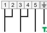 PH PH PH PH PH PH | 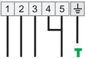 PH PH PH N PH PH PH N | ||
| Shunter : établirun pont entredeux bornes àl'aide d'unebarrette shunt | 1ère PhaseShunter 1-2Shunter 2-3NeutreShunter 4-5Terre + | 1ère PhaseShunter 1-2Shunter 2-32ème PhaseShunter 4-5Terre + | 1ère PhaseShunter 1-22ème PhaseShunter 3-43ème Phase 5Terre + | 1ère Phase 12ème Phase 23ème Phase 3NeutreShunter 4-5Terre + | ||
IMPORTANT : Fil bleu = Neutre
Fil vert/jaune = Terre
natural_image
Close-up of electrical wiring and components with a red connector (no visible text or symbols)INSTALLATION: "ENCASTREMENT"
INSTALLATION: "ENCASTREMENT"
Unpacking the appliance 14
Recommendations 14
- INSTALLATION
Safety instructions 15
Electrical connection 15/17
Fitting the hob 18/19
• USING THE APPLIANCE
Presentation of the hob 20
Technical data 20
The different hot plates ....21
Using the hot plate 21
Cooking with the hot plate 22
General maintenance 23
The hot plate 23
UNPACKING THE APPLIANCE
Inside the appliance you will find a plastic bag containing the fixing brackets to install the hob in the worktop.
RECOMMENDATIONS
PLEASE READ THE FOLLOWING CAREFULLY IN ORDER TO GET THE BEST FROM YOUR APPLIANCE.
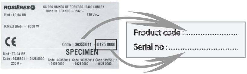
Please keep the operating and installation instructions in a safe place for future reference. Before fixing the hob, note the serial number of the appliance just in case you may require repairs from after sales service organisation.
. Rating plate (located under the lower casing of the hob)
- All accessible parts of the hob become hot while it is in operation. Always keep children away from it.
- The hob should be given a quick clean after each use, to avoid the accumulation of spillages and grease, which if not removed, will harden, and could cause the production of smoke and unpleasant smells.
- When cooking with fats or oils, never leave gas burner unattented. Overheated fats or oils can quickly catch fire.
INSTALLATION
Installing a domestic appliance can be a complicated operation which, if not carried out correctly, can seriously affect consumer safety.
It is for this reason that the task should be undertaken by a professionally qualified person who will carry it out in accordance with the technical regulations in force.
In the event that this advice is ignored and the installation is carried out by an unqualified person, ROSIERES declines all responsibility for any technical failure of the product whether or not it results in damage to goods or injury to individuals.
INSTALLATION: "ELECTRICAL CONNECTION"
The mains electricity supply connected to the appliance should comply with the norms in force in the country of installation.
Rosières declines all responsibility for any damage that may be caused by unsuitable or unreasonable use.
Warning :
- Always check before any electrical operation, the supply voltage shown on the electricity meter, the adjustment of the circuit-breaker, the continuity of the connection to earth of the installation and that the fuse is suitable.
- The electrical connection to the installation should be made via a socket with a plug with earth, or via an omnipole cut-out switch with an opening gap of at least 3mm .
- The yellow/green wire of the power supply cable must be connected to the earth of both power supply and appliance terminals.
- Rosières cannot be held responsible for any accidents resulting from the use of an appliance which is not connected to earth, or with a faulty earth connection continuity.
- Any queries regarding the power supply cord should be referred to After Sales Service or a qualified technician.
The hob "TC 04" is equipped with a supply cord type H05RR-F - area 3G2,5 mm². This power cord enables you to connect to exclusively single phase 220-240 V\~ or two phase 220-240 V2\~.
However it can be modified for connection to :
- Three phase 220-240 V3\~
- Three phase 380-415 V3N\~
To proceed to the new connection, you must adhere the following instructions
- Before making the connection, make sure that the installation is protected by a suitable fuse, see table on next page, and that it is fitted with wires of a large enough section to supply the appliance normally.
1 - Operations to be carried out on the existing connection (if necessary) :
. Turn the hob against the worktop.
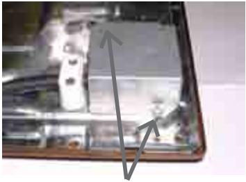
natural_image
Close-up of a damaged electronic device with visible circuitry and wiring (no text or symbols)- Unscrew the cover
Cable clamp
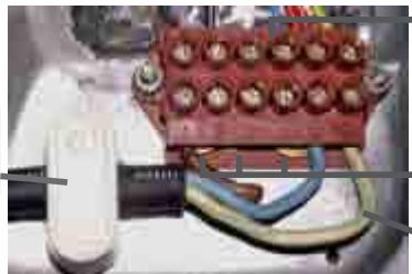
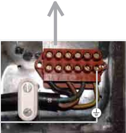
natural_image
Close-up of electrical wiring and components with no visible text or symbolsTerminal block
Shunts bars
Earth green/ yellow wire
- The hob is supplied for a single phase
. Remove the screws retaining the terminal block which contains the shunt bars and the conductors of the supply cord.
. Unscrew the cable clamp to release the power supplying cord.
. Pull out the supply cord.
2 - Operations to be carried out to make a new connection :
. Choose the supply cord in accordance with the recommendations in the table on the next page.
. The hob must be in situation as shown :
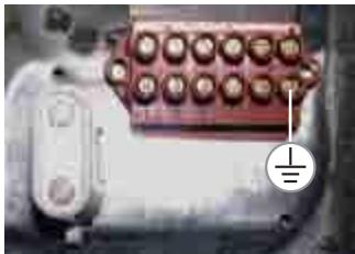
natural_image
Close-up of a red electrical connector with terminal pins and a small symbol on the right (no readable text or labels). Pass the supply cord into the clamp.
. Strip the end of each conductor of the supply cord to a 10 mm length, by taking in account the requested length of the cord for the connection on the terminal block.
. According to the installation and with the help of shunt bars which you should have recovered in the first operation, fix the conductor as shown on the chart.
. Engage the earth wire yellow/green on the earth terminal, tighten the nut and verify the continuity of the earth.
. Secure the cable clamp.
. Fix the cover.
INSTALLATION: "ELECTRICAL CONNECTION"
| Connection of origin | ||||
| Single phase220-240V~ | Two phase220-240V2~ | Three phase220-240V3~ | Three phase380-415V3N~ | |
| FUSE | 20A | 20A | 20A | 16A |
| CABLE | ||||
| Type | H05RR-F | H05RR-F | H05RR-FH05VV-F | H05RR-FH05VV-F |
| Aera | 3 G 2,5 mm2 | 3 G 2,5 mm2 | 4 G 2,5 mm2 | 5 G 1,5 mm2 |
| Connection to the terminal block | 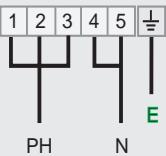 | 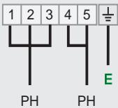 | 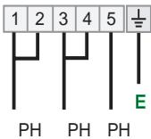 | 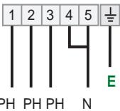 |
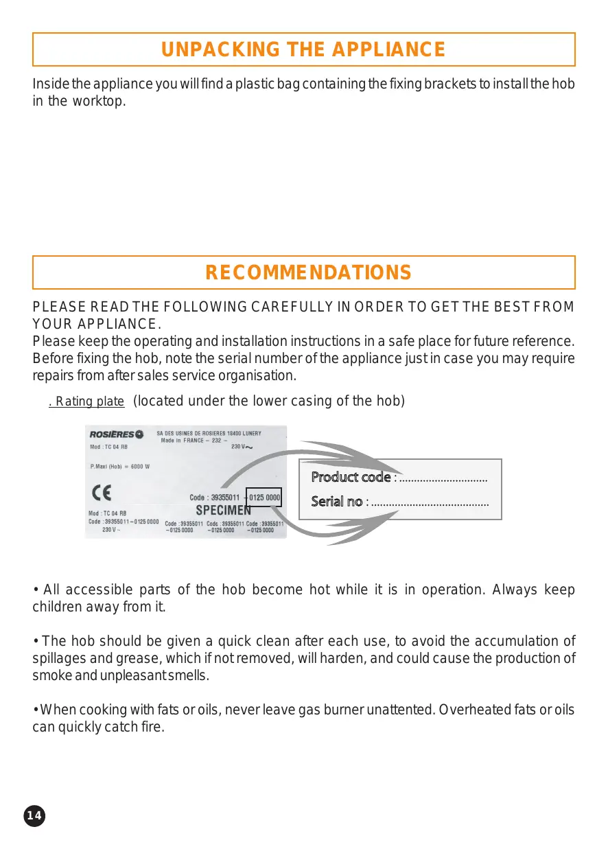
| To shunt: make a bridge with a shunt bar | 1rst PhaseShunt 1-2Shunt 2-3NeutralShunt 4-5Earth ± | 1rst PhaseShunt 1-2Shunt 2-32nd PhaseShunt 4-5Earth ± | 1rst PhaseShunt 1-22nd PhaseShunt 3-43rd Phase 5Earth ± | 1rst Phase 12nd Phase 23rd Phase 3NeutralShunt 4-5Earth ± |
IMPORTANT : Blue wire = Neutral Yellow/green wire = Earth
For the connection to the terminal block, you must :
. respect the n° 1, 2, 3, 4 and 5,
. tighten the screws,
. do not forget to fix the earth wire (yellow/green) on the earth terminal n° 6.
Example of connection Three phase
220-240V3\~ :
The earth wire must be clipped at this place.
Tighten the nut fully home......
natural_image
Close-up of an electrical connector with red and black wires, no visible text or symbolsINSTALLATION: "BUILDING-IN"
Both the unit into which the hob will be fitted and any adjacent kitchen furniture must be made from heat resistant material and fixed with heat resistant adhesive.
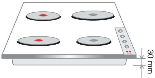
If, when installing the hob, the lower part of the casing is adjacent to an area normally accessible when handling or cleaning, fit a heatproof partition 1 cm below the base of the casing, with a 10 x 10 cm opening in the rear right-hand corner, to avoid any risk of burning or damage.
There should also be a 5 cm gap between the appliance and all adjacent vertical surfaces.
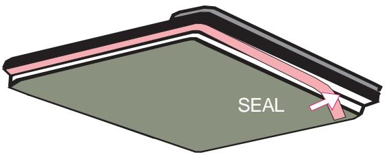
A foam adhesive seal is supplied with the hob. Stick this seal under the edge of the body as near as possible to the outer edge of the hob. Press round the edges of the hob, so that the seal flattens out and ensures an air tight seal.
Fitting the seal
Top view of the hob
Building-in according to TYPE Y (Norm EN 335-2-6)
natural_image
Illustration of a four-tier electric stove with a 30 mm height dimension label (no text or symbols on the stove itself)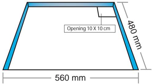
INSTALLATION: "BUILDING-IN"
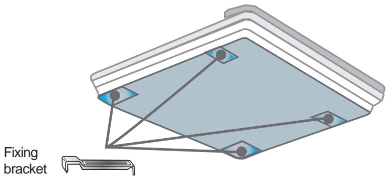
The body of the hob is fitted with 4 location holes to take the fixing brackets that secure the intended to fix the hob in the unit. Place the 4 fixing brackets in such a way that the hob surface is placed perfectly in the support unit.
Location for fixing brackets
PRESENTATION / TECHNICAL DATA
TC 04 4 ELECTRICAL HOT PLATES
Overall dimensions (cm):
Width : 59
Depth : 51
Building-in dimensions (cm) - (see chapter "Installation")
Width : 56
Depth : 48
Total electrical power : 6 kW
In order to improve the quality of the products, ROSIERES may carry out modifications linked to technical improvements.

Appliance meeting with the standard CEE 89/336, and 73/23.
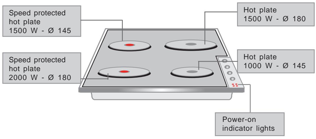
THE HOT PLATE
THE STANDARD ELECTRICAL HOT PLATE

This is a cast-iron hot plate, controlled by a 7 position switch.
Each position corresponds to a permanent and progressive temperature according to the marks 1, 2, 3, 4, 5 and 6.
RAPID SELF-PROTECTING ELECTRIC HOT PLATE (with a red dot in the centre)

This is a cast-iron hot plate, controlled by a 7 position switch.
As with the previous hot plate, each position corresponds to a
permanent and progressive temperature according to the marks 1, 2, 3, 4, 5 and 6. An internal thermostat cuts off of the power supply if there is any overheating. (If, for example, a hot plate is working without a pan on it).
BEFORE USING THE ELECTRIC HOT PLATE :
- Before using the electric hot plate for the first time, let it heat up for a few minutes, without a pan, at maximum temperature to let the protective coating harden.
HOW TO USE :
- For best results, it is advisable to start on the maximum heat and then turn back to an intermediate temperature taking into account the type and volume of the food.
- The power-on indicator light comes on to show that the hot plate is working.
- To stop it, turn back the knob until position "●".
THE DIFFERENT TEMPERATURE SETTINGS : below are a few examples which are given as guidelines. When you become more familiar with the appliance, you will be able to choose settings to suit your own personal tastes and requirements.
| Positions | Some tips ..... | |
| 1 | Very low | To keep a dish hot, melt butter and chocolate .... |
| 2 | Low | Slow cooking, sauces, stews, rice pudding, poached eggs ... |
| 3 | Moderately | Beans, frozen foods, fruit, boiling water .... |
| 4 | Medium | Steamed apples, fresh vegetables, pasta, crepes, fish .... |
| 5 | High | More intense cooking, omelettes, steaks .... |
| 6 | Very high | Steaks, chops, frying... |
For information, we note below the different powers reached according to the type of the plate and the control knob setting.
| ELECTRICAL HOT PLATE | POSITIONS | ||||||
| 7 positions | 0 | 1 | 2 | 3 | 4 | 5 | 6 |
| ∅145 - 1000 W front right | S | 100 | 165 | 250 | 500 | 750 | 1000 |
| ∅180 - 1500 W rear right | 135 | 220 | 300 | 850 | 1150 | 1500 | |
| ∅145 - 1500 W rear left | 135 | 165 | 250 | 500 | 750 | 1500 | |
| ∅180 - 2000 W front left | 175 | 220 | 300 | 850 | 1150 | 2000 | |
Cooking with the electric hot plate
To gest the best results from your appliance it is important to observe the following :
- Use thick, flat-bottomed cooking vessels, a completely flat bottom prevents the overheating of some points which cause food to stick. Thick metal allows for good heat distribution.
- Make sure that the bottoms of pans are dry : this will prevent things from sticking to the hot plate because of moisture.
- Use pans with a diameter large enough to completely cover the hot plate, otherwise some of the energy will be wasted and if there are any spillages the hot plate will quickly become stained and difficult to maintain (rust, etc).
- Never leave a hot plate switched on without a pan on it: it could become deformed, which would reduce its efficiency.
- When cooking with fat or oil, do not remove the pan from the hob. Very hot fats and oils can quickly catch fire.
- When the hot plate is hot, avoid any contact with materials made of plastic or aluminium foil.
Warning : during the hot plate is operating, it becomes hot, keep children away from it.
MAINTENANCE
Before all cleaning or dismantling operation, it is imperative to :
. disconnect the hob to the mains supply.
. let all parts of the hob cool down.
Never use :
. harsh abrasives, scouring pads or sharp object to clean the hob.
• GENERAL MAINTENANCE
THE ENAMELLED HOB
. Enamelled steel hob : simply clean the enamelled hob with soapy water when the hob is cold, rinse and wipe with a clean dry cloth. If you clean the enamelled hob when it is hot, you may tarnish it.
. Stainless steel : clean with soapy water, rinse and dry. You can use a special product to clean stainless steel which is available in stores.
THE KNOBS
For thorough cleaning, the control knobs can be removed by pulling them upwards. Clean exclusively with soapy water and dry well before replacing them.
THE HOT PLATE
Heat it for a while if necessary, to burn the deposits. After switching off and cooling down of the plate, wipe it with an absorbing paper. In any cases, it is important to protect the hot plate from humidity.
Do not use abrasive products.
To maintain and preserve the appearance, rub a drop of neutral oil, such as sewing machine oil into the surface of the hot plate.
The hot plate should always be dry, or slightly greasy, if it is not to be used for some time.
Remove any rust using emery paper followed by a suitable commercially available product.
SA DES USINES DE ROSIERES - 30, rue Y. Lacelle - Rosières - 18400 LUNERY
RCS Bourges B 553 720 053 - Capital de 18 000 000 F
Tél. 02.48.55.78.00 - Télex 780868F - Fax 02.48.68.01.75
- INSTALLATION: "LE RACCORDEMENT ELECTRIQUE"
- INSTALLATION: "ENCASTREMENT"
- - INSTALLATION
- • USING THE APPLIANCE
- UNPACKING THE APPLIANCE
- RECOMMENDATIONS
- INSTALLATION
- INSTALLATION: "ELECTRICAL CONNECTION"
- Warning :
- INSTALLATION: "BUILDING-IN"
- PRESENTATION / TECHNICAL DATA
- TC 04 4 ELECTRICAL HOT PLATES
- Overall dimensions (cm):
- Building-in dimensions (cm) - (see chapter "Installation")
- Total electrical power : 6 kW
- THE HOT PLATE
- THE STANDARD ELECTRICAL HOT PLATE
- RAPID SELF-PROTECTING ELECTRIC HOT PLATE (with a red dot in the centre)
- BEFORE USING THE ELECTRIC HOT PLATE :
- HOW TO USE :
- Cooking with the electric hot plate
- MAINTENANCE
- • GENERAL MAINTENANCE
- THE ENAMELLED HOB
- THE KNOBS
Brand : ROSIERES
Model : TC 04
Category : Electric cooktop