
TT-16 - Radio transceiver Telex - Free user manual and instructions
Find the device manual for free TT-16 Telex in PDF.


| Product Type | Intercom/Communication System |
| Brand | Telex |
| Model | TT-16 |
| Dimensions (approx.) | 20 x 15 x 5 cm |
| Weight (approx.) | 1.2 kg |
| Power Supply | 12V DC, 500 mA |
| Main Functions | Two-way communication, volume control, call alert |
| Input/Output Ports | RJ-11 for headset, 3.5mm audio jack |
| Microphone Type | Electret condenser |
| Speaker | Built-in, 8 ohms, 1W |
| Frequency Response | 300 Hz - 3.4 kHz |
| Operating Temperature | 0°C to 40°C |
| Housing Material | ABS plastic |
| Color | Black |
| Cleaning | Wipe with dry cloth; avoid solvents |
| Safety Features | Overvoltage protection, low voltage indicator |
| Spare Parts | Cables, headset, power adapter available from Telex |
| Repairability Index | 7/10 (replaceable modules) |
| Warranty | 1 year limited |
| Certification | CE, FCC |
| Manual Languages | English (default), others via translation request |
Frequently Asked Questions - TT-16 Telex
User questions about TT-16 Telex
0 question about this device. Answer the ones you know or ask your own.
Ask a new question about this device
Download the instructions for your Radio transceiver in PDF format for free! Find your manual TT-16 - Telex and take your electronic device back in hand. On this page are published all the documents necessary for the use of your device. TT-16 by Telex.
USER MANUAL TT-16 Telex
Operating Instructions
RadioCom™
Wireless IFB

TT-16
16 Channel Transmitter
TR-16
16 Channel Receiver
INTRODUCTION
WHAT IS THE TELEX WIRELESS IFB SYSTEM?
Transmitter: The transmitter generates and amplifies a RF (Radio Frequency) carrier signal, modulates this carrier with the microphone signal, and radiates the modulated RF carrier.
Receiver: The FM VHF receiver is tuned to the frequency of the transmitter. The receiver picks up the radiated RF signal from the transmitter through the antenna and converts the RF signal into audio voltages for use with an earphone, headphone, button receiver, neckloop, etc. The receiver frequency must be matched to the transmitter frequency.
The Telex Systems feature a synthesized transmitter and a synthesized receiver operating in the VHF Band between 64-68 MHz. See Table 1 for standard frequencies available.
Each transmitter channel can be utilized by any number of receivers in any given area. Up to five simultaneous systems can be used in a given area.

flowchart
graph LR
    A["SOUND SOURCE"] --> B["TRANSMITTER"]
    B --> C["FM RECEIVER"]
    C --> D["EARPHONE"]
    E["RF CARRIER SIGNAL"] --> F["ANT."]
    G["ANT."] --> H["Ant."]
Figure 1 Block Diagram of Typical Wireless IFB System
OFTEN ASKED QUESTIONS
Question: Can more than one system be used simultaneously?
Answer: Yes but never on the same frequency. You will need to have different frequencies for every receiver/transmitter combination.
Question: Is the system more sensitive in any one particular direction?
Answer: No, the transmitter's antenna radiates equally in all directions, but the signal is attenuated by your body, walls or other surrounding objects. The receiving antenna is essentially sensitive in all directions as well.
Question: Can the receiver receive other transmissions when the transmitter is turned off?
Answer: Yes it can. Telex systems operate in the VHF Band between 64-68 MHz. However, it is not susceptible to radio wave skip, CB'ers or standard FM radio transmissions. It is on TV Broadcast channels 3 and 4. So it is best to use the channels in your system that are not on the TV broadcast channel in your area. See Table 1.
The frequency your system operates on is computer selected for least interference, but there is no such thing as a 100% clear channel all the time.
If the system is going to be used in a permanent fixed location, it should operate interference free until such a time or date when someone else begins using the same frequency.
If the system is going to be moving among various locations, you may run into occasional frequency conflicts.
Whenever the system is in use, the transmitter should be left on to prevent the receiver from picking up outside interference.
Question: What is E.D.R.?
Answer: E.D.R. stands for enhanced Dynamic Range (companded) audio. E.D.R. improves the signal-to-noise ratio providing much better audio quality.
Question: Can the TT-16 and TR-16 be used with existing TR-34 and TT-44 products.
Answer: Yes, as long as the E.D.R. feature is disabled on the TT-16 and TR-16.
AVAILABLE FREQUENCIES
| Channel | Freq. in MHz | Broadcast TV Channel |
| 1 64.5 | 3 | |
| 2 64.7 | 3 | |
| 3 64.9 | 3 | |
| 4 65.1 | 3 | |
| 5 65.3 | 3 | |
| 6 65.5 | 3 | |
| 7 65.7 | 3 | |
| 8 65.9 | 3 | |
| A 66.1 | 4 | |
| B 66.3 | 4 | |
| C 66.5 | 4 | |
| D 66.7 | 4 | |
| E 66.9 | 4 | |
| F 67.1 | 4 | |
| G 67.3 | 4 | |
| H 67.5 | 4 |
Table 1 Frequencies Available
TR-16 SYNTHESIZED RECEIVER
General Description TR-16
The Telex TR-16 Receiver is a component of a system which operates on sixteen (16) user selectable channels in the 64 to 68 MHz frequency band. The receivers are designed to be used with the Telex TT-16 Transmitter.
Operating Features
Volume OFF/ON Control: This thumbwheel control serves as both an off/on switch and as a volume control. The receiver is turned off when the control is in the extreme counter-clockwise position, when viewed from the rear, and the volume is loudest when the control is in the extreme clockwise position.

Treble Control: A push button treble control is provided to enhance higher frequency audio when the button is engaged, indicated by ♿.
Headphone Jack: The receiver jack accepts a 0.140-inch (3.5 mm) diameter miniature plug. A variety of earsets or headphones can be plugged into this jack for listening.
Belt Clip: The belt clip supplied is detachable by spreading the wire apart at the tops and removing one side of the clip form the case and then the other.
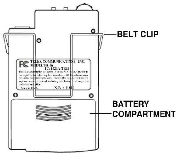

Figure 3 Operating Features TR-16
SPECIFICATIONS
TR-16 16 Channel Synthesized Receiver
Temperature Range....32 to 122 degrees F/0 to +50 degrees C
Supply Voltage 2-3 Volts, (2) AA Batteries
Battery Life....20 Hrs - Alkaline
16 Hrs - NimH
8 Hrs - NiCad
Frequency Response....100-10 kHz ±3 dB
Sensitivity (12 dB SINAD @ 66.1 MHz)....1μ V max.
Distortion....less than 2%
Audio Output @ 10% Distortion
| Battery Input Voltage | 8 ohm | 32 ohm |
| 2.0 V | 15 mW | 10 mW |
| 3.0 V | 80 mW | 50 mW |
Controls and Connections....Volume OFF/ON Switch;
Treble Control Switch; Channel Selection Switch
Audio Output Jack
TT-16 SYNTHESIZED
TRANSMITTER
General Description
The Telex TT-16 is a base station transmitter which operates in the 64-68 MHz band and accepts a wide range of audio input levels.
Operating Features

TT-16 Front Panel
- Power Button (Must be held in for 1 second to turn off.)
- Headphone volume adjustment
- Headphone Monitoring Jack
- SET Button
- Back Lit LCD Display
- UP and DOWN Adjustment Buttons
Figure 4a
Operating Features TT-16 Front Panel
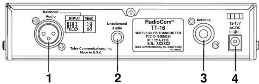
TT-16 Rear Panel
- XLR Input Connector: Accepts balanced two wire Telex, RTS channel 1 or RTS channel 2. NOTE: RTS channel 2 is compatible with *Clear-Com® Intercom Systems.
- Unbalanced Audio 14 " Input Connector.
- Antenna Jack: Accepts telescoping antenna (supplied).
- Power Input Jack: Accepts any source of 12-15 VAC/DC 300 mA minimum.
Figure 4b
Operating Features TT-16 Rear Panel

- Channel Indicator
- Audio Input Meter
- Frequency Indicator
- Enhanced Dynamic Range Indicator
-
RF Transmit Power (High when lit, Norm when not)
-
Unbalanced Audio Level
- Balanced Audio Level
- Balanced Input Selection for RTS 1, RTS 2, Telex
- Lock Out Indicator
Figure 5 LCD Display Functions
*Clear-Com® is a registered trademark of Clear-Com Intercom Systems, Inc.
TT-16 Specifications
Audio Input: Female XLR
RTS 1 Selected....Line impedance 200 Ω / Level adjustable
RTS 2 Selected....Line impedance 200 Ω / Level adjustable
Telex Selected....Line impedance 300 Ω / Level adjustable
Unbalanced Audio Input ....10K Ω input impedance/10 mV-1.0 VRMS input range
RF Power Switch....50mW in “Hi”, approx. 5mW in “Low”
AGC Range 30 dB
Signal-to-noise Ratio:
Normal 58 dB
EDR Enabled....77 dB
Pre-Emphasis....115×S
Maximum Deviation....±25 kHz
Frequency Control Crystal....+/-.005% tolerance
Available Frequencies......See Table 1, page 2
Max. Transmitter Output Power 50 mW
Power Requirements 12-15V, AC or DC @ 300 mA
Dimensions....7 ½"W x 1 3/4"H x 6 7/8"D
FCC ID....B5DM524
EQUIPMENT SET-UP AND OPERATION
TT-16 SYNTHESIZED TRANSMITTER
UNPACKING: Unpack your Wireless IFB system. If there are any damages or shortages, refer to the "Warranty Service Information" card.
TT-16 TRANSMITTER LOCATION: Select a suitable location for the TT-16 Transmitter. Try to keep a clear, unobstructed path between the transmitter and receiver and allow plenty of free space around the transmitter antenna.
ANTENNA CONNECTIONS: Connect the telescoping antenna to the rear panel ANTENNA jack.
For best results, the antenna should be vertically aligned. Tighten the knurled ring to hold the antenna in place, and extend the antenna to full length.

Figure 6 Antenna Connection
POWER CONNECTION: Plug the AC power adapter into an electrical outlet. Plug the other end of the cord into the power input jack on the rear panel of the TT-16.
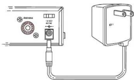
Figure 7 Connecting Power
SYSTEM SET UP
All of the channel and input selection functions are accessed from the front panel. Press SET button once to begin System Setup. Whenever a function is flashing, the UP and DOWN buttons can be used to adjust it. Once set, the next function will start to flash. To access a specific function, press SET until the function is flashing, the features are accessed in the following order:
Channel
RF Power Output
Unbalanced Level Adjust
Balanced Input (RTS1/RTS2/Telex)
Balanced Level Adjust
Channel Selection
Turn the TT-16 on by touching the POWER button. (The TT-16 is designed to return to "on" if power is disconnected while the unit is on. This is so the unit can be switched on and off with a power strip or rack power).
The LCD display will light up and show the Channel, Audio Meter, Frequency (and E.D.R. if it has been enabled). Press the SET button once and Channel letter will flash. Use the UP and DOWN Arrow buttons to select the desired channel 1-9 and A-H. Press SET when the desired channel is displayed and the channel is set. The channel letter will stop flashing and the RF Power indicator will flash.
RF Power Selection
While the "RF Power" indicator is flashing, press the UP ARROW for HIGH and DOWN for NORM (the "RF Power" line will flash quickly and will disappear when SET is pressed). NORM power should be used for small to medium sized venues and whenever multiple systems are being used. Press SET when the power is set and the Unbalanced Input level will flash.
Unbalanced Input And Level Adjustment
If the unbalanced audio input will not be used, with the "Unbalanced Audio Level" flashing use the DOWN button to set the level to OFF and press set to go to Balance Input Selection.
If the Unbalanced input will be used, connect the input now and apply audio content. With the audio content playing and "Unbalanced Audio Level" flashing, watch the audio meter. The peak signal should not go above the 0 dB segment, use the UP and DOWN buttons to adjust the input level so that the loudest input lights up the 0 dB segment. When the level is set, press the SET button and one of the input options will flash.
Balanced Intercom Input and Level Adjustment
With the Balanced Intercom Input selection flashing (RTS1, RTS2, or TELEX). Use the UP and DOWN buttons to scroll to the correct input. With the correct input displayed, press SET and the "Balanced Audio Level" indicator will flash.
If the intercom audio input will not be used, with one of the Balanced Input options flashing press SET so the "Balanced Audio Level" is flashing. Use the DOWN button to set the level to OFF and press SET to end the setup session. When OFF is selected "Balanced Audio Level" will not be displayed on the screen.
If the Balanced Input Selection will be used, then connect the input and apply audio content. With the audio content playing and "Balanced Audio Level" flashing, watch the audio meter. The peak signal should not go above the 0 dB segment, use the UP and DOWN buttons to adjust the input level so that the loudest input lights up the 0 dB segment. When the level is set, press the SET button and the Setup Session will end.
NOTE: The TT-16 will operate with both Unbalanced and Balanced inputs active at the same time.
Enhanced Dynamic Range (E.D.R.) Operation
The Telex TT-16 Transmitter is equipped with E.D.R., Enhanced Dynamic Range (companded) audio. This mode greatly improves the Audio Signal to Noise Ratio when used with the Telex Model TR-16 receiver. The E.D.R. mode must be selected on both the transmitter and receiver to be effective. If using the TT-16 with TR-34 IFB units, E.D.R. must be turned off.
1) To engage the E.D.R. function, turn the TT-16 off with the power switch. (The power switch must be held for 1 second to turn unit off.)
2) Press and hold the SET button while you turn the TT-16 back on. The E.D.R. symbol will be displayed in the lower right corner to indicate the mode is active.
3) Repeat the procedure to disable the E.D.R function.
Lock Out
The TT-16 SET button can be locked to prevent E.D.R. activation, and unintended channel changes.
1) To engage the Lock Out Feature, press the UP and DOWN buttons at the same time and hold them down for two seconds.
2) The padlock symbol will appear and the set button is disabled.
3) To unlock the system, press the UP and DOWN buttons and hold them for two seconds or until the padlock symbol disappears.
Audio Monitor
Turn the Monitor (volume) control all the way down (counterclockwise). After the audio input levels have been adjusted, Stereo headphones with a 3.5 mm or 14 in. plug can be plugged into the Monitor jack. If you wish to monitor the audio program material, turn up the monitor (volume) control to the desired level. The monitor control does not affect the transmitted audio level.
MULTIPLE SYSTEM INSTALLATIONS: As with any radio device, interference can occur at any time. The frequencies offered are shared with other legitimate users. The severity of interference varies with the distance to the interfering station. Multiple systems further complicate installations. The following steps are suggested in order to achieve best results in your installation.
-
In order to determine whether your selected frequencies have minimum interference, Telex recommends that you first temporarily install the receivers in your proposed setting and monitor the channel for interference. To do this (with fresh batteries installed) turn on your receiver, but DO NOT turn on any other receiver or transmitter at this time. If audible interference is present, this may indicate another user on the channel. Monitoring should be repeated for each channel that you propose to use. DO NOT use channels that have interference.
-
Set your transmitter(s) to channels with no or minimum interference. Each transmitter must be set to a separate frequency. For best results when using multiple transmitters, each transmitter should be installed separately as far as possible from the others.
-
Turn on the transmitter(s) with an active audio input. Test walk a receiver through the expected listening area to verify coverage. The system should now be ready for use.
TR-16 SYNTHESIZED RECEIVER
Keep a clear, unobstructed path between the transmitter and receiver antennas for a clear transmission.

- Channel Display 1-9 through A-H and low battery indicator
- Lock Indicator (see Change Lock Out)
- High Frequency Emphasis Indicator (on when symbol is showing)
- Enhanced Dynamic Range Indicator.
Figure 8 TR-16 Display
Channel Selection
1) Turn the receiver on. A channel letter will show in the display.
2) Press the SET button once and the Channel indicator will flash.
3) Press the ♂ button and the Channel will scroll up, match the channel to the transmitter channel being used (TT-16, TT-44).
4) Press SET, the channel indicator will stop flashing and the channel is set.
Enhanced Dynamic Range (E.D.R.) Operation
The Telex TT-16 transmitter is equipped with E.D.R., Enhanced Dynamic Range (companded) audio. This mode greatly improves the Audio Signal to Noise Ratio when used with the Telex Model TR-16 receiver. The E.D.R. mode must be selected on both the transmitter and receiver to be effective. If using the TR-16 with a TT-44 IFB Transmitter, E.D.R. must be turned off.
1) To engage the E.D.R function turn the TR-16 off with the volume control thumb wheel.
2) Press and hold the SET button while you turn the TR-16 back on. The E.D.R. symbol will be displayed in the lower right corner to indicate the mode is active.
3) Repeat the procedure to disable the E.D.R. function.
Lock Out
The TR-16 SET button can be locked to prevent E.D.R. activation, and unintended channel changes. The High Frequency Emphasis button will remain active at all times for the convenience of the user.
1) To engage the Lock Out Feature, press the SET and ♂ buttons at the same time and hold them down for 5 seconds.
2) The padlock symbol will appear and the set button is disabled.
3) To unlock the system, press the SET and ♂ buttons and hold them for 5 seconds or until the padlock symbol disappears.

Low Battery Indication
1) When there is approximately 10% of the battery life left, an animated battery symbol will flash alternately with the channel letter in the LCD display.
2) When there is only 5% battery life left, the battery symbol will constantly flash in the display.

Low Battery Display
BATTERY REPLACEMENT
The TR-16 Receiver uses two (2) AA batteries. When the batteries are low the sound will be distorted. Replace weak batteries with two fresh AA batteries, and position them in the battery compartment as illustrated in Figure 9.
For additional information refer to the “Battery Information” Section.
NOTE: If the unit is to be stored for any length of time make sure you remove the batteries from the unit.
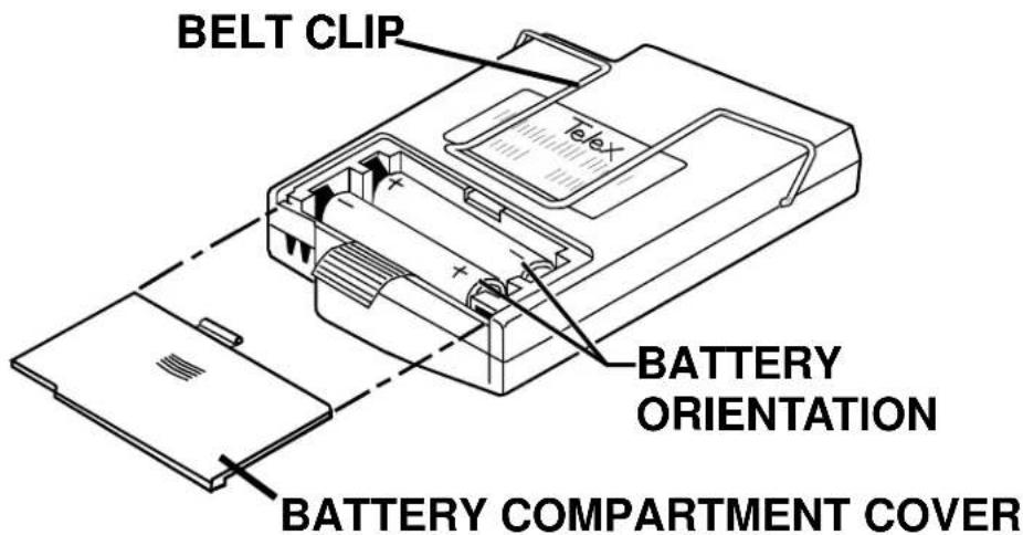
Figure 9 Battery Installation - TR-16
BATTERY INFORMATION
General
Improper battery selection, use, installation and care are the cause of numerous wireless system failures.
Alkaline Batteries
Alkaline batteries such as Mallory's DURACELL® or Eveready's ENERGIZER® provide the most reliable operation in wireless transmitters and receivers. The use of low cost carbon-zinc batteries is NOT RECOMMENDED.
*ENERGIZER® is a registered trademark of Union Carbide
Corporation.
*DURACELL® is a registered trademark of Duracell Inc.
ANTENNA INFORMATION
Antenna Alignment

Figure 10 Antenna Alignment Good and Bad
Antenna Placement
Proper antenna placement probably has the most effect on your TELEX Wireless System's overall performance. Following the suggestions that follow should result in “dropout free” performance.

flowchart
graph LR
    A["Radio Station"] <--> B["Wireless Device"]
    C["Radio Station"] <--> D["Wireless Device"]
Figure 11 Distance Between Transmitter and Receiver
Keep the distance between the transmitter and the receiver(s) as short as possible. The greater the distance the weaker the signal.
Make sure the “signal path” between the transmitter and receiver(s) is unobstructed. You should always be able to visually locate the antenna of the transmitter at all times.
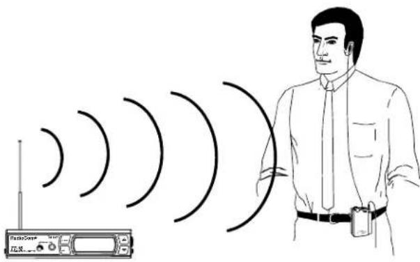
SIGNAL REACHES ANTENNA AT FULL STRENGTH WITH NO OBSTRUCTIONS.
Figure 12 Keeping Site Clear to Antenna
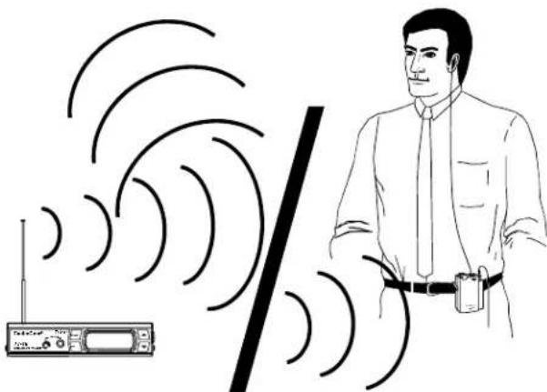
Attempting to operate the sound enhancement system through or around walls, ceilings, metal objects, etc., will reduce system range and performance.
natural_image
Illustration of a person standing beside a radio with signal waves, no text or symbols presentSIGNAL REFLECTION OFF A METAL OBSTRUCTION CAUSES REDUCED SIGNAL AND "MULTIPATH"
Figure 13 Operating Through Obstruction
DO NOT - Mount the transmitter on, or next to, metal such as beams, walls with metal studs, etc. This will “detune” the transmitter antenna which can result in loss of signal at the receiver.

Figure 14 Transmitter Antenna Placement
TROUBLESHOOTING
Reread the sections of this manual to make sure you have completed system set-up properly.
If you are unable to solve the problem, contact the dealer from whom you purchased the system for assistance.
| PROBLEM | SOLUTION |
| DISTORTION -System's audio quality seems distorted at medium to high input levels | Reduce audio gain on transmitter by adjusting the gain controls. |
| HISS - System seems to produce a "hiss" which is undesirable. | Check the gain settings on the transmitter and the volume control on the receiver. They may be too low. |
| DROPOUTS - When moving around the area in which you will be using the system there seem to be locations where the signal "swooshes" or completely disappears. | Make sure the antenna is connected and fully extended. Follow the location suggestions on page 15. Change the location of the transmitter antenna or avoid the bad area with the receivers. |
| INTERFERENCE - System picks up signals other than the TT-16 Transmitter. | Make sure the Telex TT-16 is turned on - this will usually eliminate the interference signal.If problem persist with the transmitter "ON", try changing to another channel. |
| REDUCED DISTANCE - System doesn't operate as far as it once did. System doesn't' operate as well as you think it should. | Receiver Battery is possibly in need of replacement. Transmitter antenna possible located incorrectly. Receiver not tuned properly. |
| BATTERIES DON'T LAST | If using "throw away" batteries make sure they are alkaline. If using nickel-cadmium or nickel metal hydride batteries make sure they were fully charged when yo are using them and fully drained when you are done before recharging them. |
| HUM - Audio System emits hum or buzz thru speakers and sound enhancement receiver. | Locate Transmitter away from the audio equipment. |
| Transmission sounds compressed on TR-16 | E.D.R. function may be engaged on the TT-16. See setting E.D.R. function on page 9. The E.D.R. feature can only be used with the TR-16 and must be active on both transmitter and receiver to be effective. |
| SET button does not work, cannot change channel | Lock Out is engaged, press and hold UP and DOWN buttons until the padlock symbol disappears. |
FCC INFORMATION
The Telex TR-16 receiver is authorized under part 15 of the FCC Regulations. Changes or modifications to this equipment could void the user's authority to operate the equipment.
The Telex Model TT-16 transmitter is authorized under Federal Communications Commission and Industry Canada Rules. Licensing of the Transmitter, if required, is the users responsibility and licensability depends upon the users classification, and frequency selected.
CAUTION: Changes or modifications made by the user could void the user's authority to operate the equipment.
Operation is subject to the following two conditions: (1) This device may not cause interference, and (2) This device must accept any interference, including interference that may cause undesired operation of the device.
ACCESSORIES
CES-2 complete TeleThin® Announcer Earset....800318000
(includes TRV-04 125 ohm TeleThin® Receiver, CMT-98 5ft TeleThin®)
Grey cordset and ET-4 Coiled Eartube)
SEB-1 Single Earbud with Cord....59840005
DEB-2 Dual Earbud with Cord....59840001
HED-2 Collapsible Lightweight Headphone....59840007
HED-3 Full Cushion Noise Reduction Headphone....63510021
TW-A 1/4 Wave Telescoping Antenna for TT-16 877960
PA-2 USA Power Supply for TT-16 730139
RM-S Single Rack Mount for TT-16....71081001
RM-D Dual Rack Mount for TT-16....71081002
TR-16 Belt Clip 358815
TELEX®
TELEX COMMUNICATIONS, INC. 12000 Portland Ave. South, Burnsville, MN 55337, U.S.A.
- Operating Instructions
- RadioCom™
- Wireless IFB
- TT-16
- TR-16
- INTRODUCTION
- WHAT IS THE TELEX WIRELESS IFB SYSTEM?
- OFTEN ASKED QUESTIONS
- TR-16 SYNTHESIZED RECEIVER
- General Description TR-16
- Operating Features
- SPECIFICATIONS
- TR-16 16 Channel Synthesized Receiver
- TT-16 SYNTHESIZED
- TRANSMITTER
- General Description
- TT-16 Front Panel
- TT-16 Rear Panel
- TT-16 Specifications
- EQUIPMENT SET-UP AND OPERATION
- TT-16 SYNTHESIZED TRANSMITTER
- SYSTEM SET UP
- Channel Selection
- RF Power Selection
- Unbalanced Input And Level Adjustment
- Balanced Intercom Input and Level Adjustment
- Enhanced Dynamic Range (E.D.R.) Operation
- Lock Out
- Audio Monitor
- Low Battery Indication
- BATTERY REPLACEMENT
- BATTERY INFORMATION
- General
- Alkaline Batteries
- ANTENNA INFORMATION
- Antenna Placement
- TROUBLESHOOTING
- FCC INFORMATION
- ACCESSORIES
Brand : Telex
Model : TT-16
Category : Radio transceiver