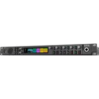
RTS OMS OMNEO - Professional audio equipment Telex - Free user manual and instructions
Find the device manual for free RTS OMS OMNEO Telex in PDF.


| Product Type | Intercom System |
| Brand | Telex (RTS) |
| Model | RTS OMS OMNEO |
| Dimensions (HxWxD) | 1U rackmount (44 x 483 x 200 mm) |
| Weight | 4.5 kg |
| Power Supply | 100-240 VAC, 50/60 Hz, 60W |
| Audio Channels | Up to 24 channels |
| Communication Protocol | OMNEO (Ethernet-based) |
| Supported Devices | Intercom panels, beltpacks, and keypanels |
| Main Functions | Two-way intercom, party line, point-to-point, conference calling |
| Audio Quality | Low latency, high-definition audio |
| Connectivity | Ethernet (RJ45), XLR analog audio, GPIO |
| Control Interface | Web-based configuration, RS232 |
| Compliance | CE, FCC, RoHS |
| Operating Temperature | 0°C to 40°C |
| Maintenance | Clean with dry cloth; no liquid cleaners |
| Safety | Overcurrent protection, surge protection |
| Spare Parts | Power supply module, network card, connector modules |
| Repairability | Modular design; hot-swappable components |
Frequently Asked Questions - RTS OMS OMNEO Telex
User questions about RTS OMS OMNEO Telex
0 question about this device. Answer the ones you know or ask your own.
Ask a new question about this device
Download the instructions for your Professional audio equipment in PDF format for free! Find your manual RTS OMS OMNEO - Telex and take your electronic device back in hand. On this page are published all the documents necessary for the use of your device. RTS OMS OMNEO by Telex.
USER MANUAL RTS OMS OMNEO Telex
OMS OMNEO Main Station
natural_image
Line drawing of a server rack with ports, connectors, and ventilation grilles (no text or labels)en
Technical Manual
Table of contents
| 1 | Safety 7 | |
| 1.1 Copyright and Disclaimer 7 | ||
| 1.2 Notices 7 | ||
| 1.3 Important safety instructions 8 | ||
| 2 | OMS Models 9 | |
| 2.1 Applicable products 9 | ||
| 2.2 Model matrix 9 | ||
| 3 | Introduction 11 | |
| 4 | OMS reference view 12 | |
| 5 | Keypad reference view 14 | |
| 6 | Installation 17 | |
| 6.1 System Interface Requirements 17 | ||
| 6.2 Rack mounting instructions 18 | ||
| 7 | Cables and cable requirements 19 | |
| 7.1 Connector pinouts | 19 | |
| 7.2 TIF and legacy keypanel cable overview | 23 | |
| 7.3 RJ45 Ethernet connectors | 23 | |
| 7.4 Network port cabling | 24 | |
| 8 | System configuration | 25 |
| 8.1 Configure network ports | 25 | |
| 8.2 Configure the Control interface | 25 | |
| 8.3 Configure the OMNEO interface | 26 | |
| 8.4 Configure the RVON interface | 27 | |
| 9 | Intercom configuration 28 | |
| 9.1 Port configuration | 28 | |
| 9.1.1 | Connect 2-Wire devices to OMS | 28 |
| 9.1.2 | Connect 4-wire analog devices to OMS | 29 |
| 9.1.3 | Connect OMNEO devices to OMS using Connect Devices | 29 |
| 9.1.4 | Connect OMNEO devices to OMS | 30 |
| 9.1.5 | Connect RVON devices to OMS | 31 |
| 9.1.6 | Add devices to the device catalog in IPedit | 33 |
| 9.1.7 | Configure an OMNEO channel for OMS using IPedit | 34 |
| 9.1.8 | Configure an OMNEO device to connect to OMS | 36 |
| 9.1.9 | Configure an RVON channel for OMS using IPedit | 36 |
| 9.1.10 | Configure an RVON keypanel to connect to OMS | 37 |
| 9.1.11 | Configure OMNEO keypanels using IPedit | 38 |
| 9.1.12 | Configure RVON keypanels using IPedit | 39 |
| 10 | Basic operation | 40 |
| 10.1 | Navigating the menu | 40 |
| 10.2 | Editing field data | 42 |
| 10.3 | Local keypanel icons | 44 |
| 10.4 | OMS menu icons and descriptions | 46 |
| 10.5 | Port status overview | 58 |
| 10.6 | Link status overview | 59 |
| 10.7 | Page change | 60 |
| 10.8 | Party Line Call window | 61 |
| 10.9 | Call waiting window | 62 |
| 10.10 | UPG | 63 |
10.11 Mic kill 63
10.12 Info button 64
10.13 All call 65
10.14 All talk 65
10.15 Key assignment mode 65
10.16 SA keypad button 66
10.17 RSTP 67
10.18 Factory reset 67
10.19 Front panel reset button 67
11 Download firmware 69
11.1 Download firmware using AZedit 69
11.2 Download firmware using Firmware Upload Tool 70
11.3 Download splash screen 72
11.4 Download screen saver 73
11.5 Download licenses 74
12 Main menu access 77
13 Status | System menu 78
13.1 OMS version 78
13.2 AZedit sessions 78
13.3 IPedit sessions 79
13.4 Size 79
14 Status | Network menu 81
14.1 Control port 81
14.2 OMNEO (SFP) 81
14.3 OMNEO (RJ45) 83
14.4 RVON 83
15 Status | Ports menu 85
15.1 OMNEO 85
15.2 RVON 86
15.3 AIO 87
15.4 2-Wire 88
15.5 Devices 89
15.6 TIF 89
16 Status | Peripherals menu 91
16.1 GPIO-16 91
17 Status | Intercom menu 92
17.1 GPIO 92
17.2 Crosspoint inspect 92
18 Status | Hardware menu 94
18.1 Power supplies 94
18.2 Temperatures 95
18.3 Clock 96
19 Status | Key Status menu 97
20 Configuration | System menu 98
20.1 Intercom name 98
21 Configuration | Network menu 99
21.1 Control port 99
21.2 OMNEO 99
21.3 RVON 100
| 22 | Configuration | Ports menu 102 | |
| 22.1 | Connect Devices 102 | |
| 22.2 | OMNEO channels 103 | |
| 22.3 | RVON channels 103 | |
| 22.4 | 2-Wire ports 104 | |
| 23 | Configuration | Audio menu 106 | |
| 23.1 | Headset Mic / Speaker 106 | |
| 23.2 | Panel mic / speaker 108 | |
| 23.3 | Filters 110 | |
| 23.3.1 | Panel mic 111 | |
| 23.3.2 | Headset mic 112 | |
| 23.3.3 | Speaker 113 | |
| 23.3.4 | Headset Speaker 114 | |
| 23.4 | Mic options | 115 |
| 23.5 | Tone generator | 115 |
| 23.6 | Key volumes 116 | |
| 23.7 | Miscellaneous | 116 |
| 24 | Configuration | Local Keypanel menu | 117 |
| 24.1 | Key options | 117 |
| 24.2 | Auto dial | 118 |
| 24.3 | Panel Swap | 119 |
| 24.4 | Page Change | 119 |
| 24.5 | Call waiting window | 120 |
| 24.6 | Footswitch | 120 |
| 24.7 | Display Options | 121 |
| 25 | Configuration | User Preferences menu | 123 |
| 25.1 | Brightness | 123 |
| 25.2 | Screen saver | 123 |
| 25.3 | Alpha size | 124 |
| 25.4 | Keypad | 124 |
| 25.5 | Options | 125 |
| 25.6 | Keypad hotkeys | 126 |
| 25.7 | Signaling | 127 |
| 26 | Configuration | Advanced menu | 128 |
| 26.1 | Authentication menu | 128 |
| 26.1.1 | AZedit | 128 |
| 26.1.2 | IPedit | 129 |
| 26.1.3 | Front panel | 129 |
| 26.1.4 | Debug Shell | 131 |
| 26.2 | GPIO-16 menu | 131 |
| 26.3 | Clock Select | 131 |
| 26.4 | Soft Reset | 132 |
| 26.5 | Diagnostics | 132 |
| 26.5.1 | Test Panel | 132 |
| 27 | Intercom setup | Party line membership | 134 |
| 28 | Intercom setup | Stored Setups menu | 137 |
| 28.1 | Stored setups window | 138 |
| 29 | Intercom setup | Devices menu | 140 |
| 29.1 | Key assignments | 140 |
6 en | Table of contents OMS OMNEO Main Station
29.2 Setup pages 141
29.3 Scroll enables 142
30 Intercom setup | Resources menu 144
30.1 Party line 144
30.2 IFB 145
30.3 Special list 147
30.4 Relay 148
30.5 ISO 148
31 Intercom setup | Gains menu 150
31.1 I/O 150
31.2 Crosspoint 151
31.3 Party line 151
32 Intercom Setup | Alphas menu 153
32.1 Alphas 153
33 Alarms menu 155
33.1 Alarms | Unacknowledged 155
33.2 Alarms | Active 156
33.3 Alarm troubleshooting 158
34 Technical data 162
1 Safety
1.1 Copyright and Disclaimer
All rights reserved. The product information and design disclosed herein were originated by and are the property of Bosch Security Systems, LLC. Bosch reserves all patent, proprietary design, manufacturing, reproduction, use and sales rights thereto, and to any article disclosed therein, except to the extent rights are expressly granted to others.
No part of this document may be reproduced or transmitted in any form by any means, electronic, mechanical, photocopying, recording, or otherwise, without the prior written permission of the publisher. For information on getting permission for reprints and excerpts, contact Bosch Security Systems, LLC.
All other trademarks are property of their respective owners.
The content and illustrations are subject to change without prior notice.
1.2 Notices

CAUTION
RISK OF ELECTRIC SHOCK DO NOT OPEN

The lightning flash and arrowhead within the triangle is a warning sign alerting you of dangerous voltage inside the product.
Caution: To reduce the risk of electric shock, do not remove cover. No user-serviceable parts inside. Refer servicing to qualified service personnel
The exclamation point within the triangle is a warning sign alerting you of important instructions accompanying the product.
See marking on bottom/back of product.

Warning!
Apparatus shall not be exposed to dripping or splashing and no objects filled with liquids, such as vases, shall be placed on the apparatus.

Warning!
The main power plug must remain readily operable.

Caution!
To reduce the risk of electric shock, grounding of the center pin of this plug must be maintained.

Warning!
To reduce the risk of fire or electric shock, do not expose this apparatus to rain or moisture.
| ~ | This product is AC only. | |
| CE | CE Compliant and UL Certified | |

Warning!
This is a CLASS A product. In a domestic environment, this product may cause radio interference, in which case the user may be required to take adequate measures.
1.3 Important safety instructions
- Read these instructions.
- Keep these instructions.
- Heed all warnings.
- Follow all instructions.
- Do not use this apparatus near water.
- Clean only with a dry cloth.
- Do not block any ventilation openings. Install in accordance with the manufacturer's instructions.
- Do not install near any heat sources such as radiators, heat registers, stoves, or other apparatus (including amplifiers) that produce heat.
- Do not defeat the safety purpose of the polarized or grounding-type plug. A polarized plug has two blades with one wider than the other. A grounding type plug has two blades and a third grounding prong. The wide blade or the third prong is provided for your safety. If the provided plug does not fit into your outlet, consult an electrician for replacement of the obsolete outlet.
- Protect the power cord from being walked on or pinched particularly at plugs, convenience receptacles, and the point where they exit from the apparatus.
- Only use attachments/accessories specified by the manufacturer.
- Use only with the cart, stand, tripod, bracket, or table specified by the manufacturer, or with the apparatus. When a cart is used, use caution when moving the cart/apparatus combination to avoid injury from tip-over.
- Unplug the apparatus during lightning storms or when unused for long periods of time.
- Refer all servicing to qualified service personnel. Servicing is required when the apparatus has been damaged in any way, such as power-supply cord or plug is damaged, liquid has been spilled or objects have fallen into the apparatus, the apparatus has been exposed to rain or moisture, does not operate normally, or has been dropped.
2 OMS Models
2.1 Applicable products
This manual is applicable to these products:
- OMS ANALOG 4M
- OMS ANALOG 4F
- OMS ANALOG 5F
- OMS PLUS 4M
- OMS PLUS 4F
- OMS PLUS 5F
- OMS BASIC 4M
- OMS BASIC 4F
- OMS BASIC 5F
- OMS INTERMED 4M
- OMS INTERMED 4F
- OMS INTERMED 5F
- OMS ADVANCED 4M
- OMS ADVANCED 4F
- OMS ADVANCED 5F
2.2 Model matrix
OMS allows the user to upgrade and expand the set of available features without any changes to the hardware. The features detailed are licensed and are available for purchase.
| Feature Analog | Analog Plus B | Basic Intermediate | Advanced | ||
| Analog 2-Wire ports (RTS/Audiocom/CC) | 4 4 0 4 4 | ||||
| Number of Party Lines | 4 16 16 | 16 16 | |||
| 2-Wire Mixing / Routing | Yes Yes No | Yes Yes | |||
| 4-Wire AIO ports 0 4 0 | 4 4 | ||||
| Tie Lines for system expansion | 0 8 8 8 8 | ||||
| Maximum OMNEO Device Connections ^1 | 0 0 20 20 | 40 | |||
| Digital belt packs | 0 0 20 20 | 40 | |||
| ROAMEO belt packs | 0 0 0 | 20 | 40 | ||
| RVON ports | 0 0 0 0 4 | ||||
| Keypanel Capacity | 0 | 4 (analog only) | 4 4 8 | ||
| OMNEO fiber interfaces | No | No | No | Yes Yes |
Tab. 2.1: Features and Models
^1 Both digital and wireless belt pack capacity comes out of this same pool of resources To determine the model running on the device, do the following:
- On the front of the OMS, press the MENU button.
The Main menu home screen displays the current model.

3 Introduction
The OMS Main Station is the beginning of a new era of intercom systems called RTS Digital Partyline. This powerful single system bridges legacy analog partyline users who wish to migrate to digital connectivity while using their existing equipment. Furthermore, OMS connects both wired and wireless intercom products. OMS represents an incredibly versatile and easy-to-use solution for a wide range of applications - a communications multi-tool for theaters, houses of worship, industrial, broadcast, and event venues.
Using OMNEO, OMS interconnects with the digital matrix products including keypanels, ROAMEO wireless and digital beltpacks. OMNEO is an architectural approach to connecting devices that need to exchange information such as audio content or device control (Dante & control). In addition, OMS can serve as a stand-alone base station for ROAMEO, RTS' digital wireless communication solution based upon DECT.
The OMS is available in five licensed models; Analog, Analog Plus, Basic, Intermediate and Advanced. The OMS allows for increased capacity and functionality as business needs grow. The OMS has the easy-to-use RTS digital icon-based front panel display along with a simplified menu structure to allow system configuration and control from the front panel and display.
- Supports 4 ports of analog AIO 4-wire and 4 ports of analog 2-Wire (RTS / Audiocom / Clear-Com formats supported). Auto nulling (echo cancellation) capability available on 2-Wire interfaces.
- Supports up to 8 keypanels (any mix of analog/OMNEO/RVON) depending upon product licensing (maximum four analog).
- Supports up to 40 OMNEO or ROAMEO beltpacks and up to 16 party lines. Ethernet connectivity through copper or fiber connections available.
- Up to 4 RVON channels available with the Advanced license for remote networking with other RVON capable equipment. G.711a, G.711μ, G.729ab and G.722 codecs supported.
– Includes stage announce output and additional OMNEO expansion audio ports reserved for connecting and networking with other OMS units. These expansion ports allow additional system capacity and partyline capability as part of a distributed system.
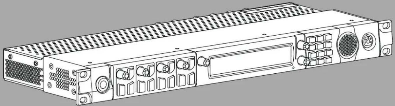
4 OMS reference view
Front panel

Figure 4.1: OMS front panel reference view
| 1 Key | volume encoder knob | |
| 2 Call | button | |
| 3 ENC | 1 encoder knob Left encoder knob | |
| 4 High | resolution LCD display | |
| 5 ENC | 2 encoder knob Right encoder knob | |
| 6 Keypad | ||
| 7 Speaker | ||
| 8 Headset connector | ||
| 9 Microphone connector 1⁄4" microphone plug | ||
| 10 Talk button | ||
| 11 Listen button | ||
| 12 Reset switch | ||
| 13 Volume knob | ||
Rear panel

Figure 4.2: Rear panel reference view
| 1 Control port Ethernet connector | |
| 2 AC power connector | |
| 3 2W party line CH A, CH B, CH C, and CH D | 3-pin XLR female connector |
| 4 PGM 1 input 3-pin XLR female connector | |
| 5 PGM 2 input 3-pin XLR female connector | |
| 6 Stage announce output 3-pin XLR male connector | |
| 7 AIO analog connectors 4x (ports 1 through 4) | |
| 8 GPIO connector 24-position terminal block | |
| 9 RVON port Ethernet connector | |
| 10 OMNEO port 2x Ethernet connectors | |
| 12 OMNEO port 2x Optical (fiber) connectors |
5 Keypad reference view
There are three modes of operation for the keypanel keypad: Primary Mode and SHIFT Mode (DIAL mode is a secondary function of SHIFT Mode).
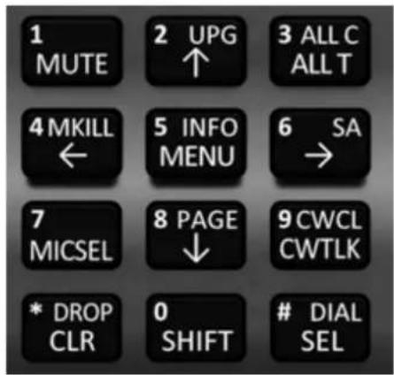
Figure 5.1: OMS Keypad
Primary Mode
Use primary mode for the most common keypanel functions, such as CLR, SEL, and accessing the Main menu. There are no special keypad sequences to use these functions.
SHIFT Mode
Use SHIFT mode to access more utilities on the keypad. When the keypad is in SHIFT mode, pressing the keypad keys perform secondary functions. The SHIFT mode functions are located on the keypad keys. The SHIFT functions available: DROP, DIAL, PAGE, CWCL, MKILL, INFO, SA, UPG, and ALL C.
To access SHIFT mode,
- Press the SHIFT button.
- Press the secondary function desired.

Notice!
Once SHIFT mode is entered, exit the mode by pressing the SHIFT key again, without pressing any other keys. It also exits after a timeout.

Notice!
When SHIFT +
If the user is instructed to press two keys simultaneously, this manual uses the phrase press and hold.
DIAL Mode
Use DIAL mode to complete telephone operations. When the OMS is in DIAL mode, the keypad keys support the standard telephone keypad configuration as a third tier function. The DTMF keypad is in the upper-left corner of the keypad keys.
To access DIAL mode, do the following:
- Press the SHIFT key.
- Press the DIAL key.
- Press and hold one of the OMS talk buttons.
- While holding the talk button, enter the phone number using the keypad.
- Release the talk button when the phone number is entered.
| Keypad Mode | Dial Mode Shift | Mode Description | |
| MUTE 1 The | MUTE button | mutes the p | panel microphone, headset microphone or both at the same time. The microphone mute operation can be configured as momentary, toggle or disabled. |
| ↑ 2 UPG | Use the UP button to navigate through menus. Use the UPG (User Programmable) function to configure changes to panel swap rows. | ||
| ALL T 3 ALL C | The ALL T button activates the talk on every party line assignment across every row of talk buttons. The ALL C button sends a call to every party line assignment across every row of listen buttons. Devices that are members of those party lines receive a notification. Notification types are a combination of visual, audible or haptic vibration. | ||
| ← 4 MKILL | Use the LEFT button to navigate through menus. The MKILL function sends a mic kill command to other devices in the system. For every party line the OMS is talking to, the mic kill command is sent to all devices that are members of those party lines. | ||
| MENU 5 | INFO | The MENU button accesses the top-level OMS main menu. The INFO function shows the port status overview screen. | |
| → 6 SA | Use the RIGHT button to navigate through menus. Use the SA function to activate a voice page, where the audio is routed to a public address system connected to the SA output so announcements can be made to many users simultaneously. | ||
| MICSEL 7 Use the MICSEL button to switch between panel mic mode or headset mode. | |||
| ↓ 8 | PAGE | Use the DOWN button to navigate through menus. Use the PAGE function to access a different setup page. There are four setup pages. | |
| CWTLK | 9 CWCL | Use the CWTLK button to answer a call in the CWW window. Use the CWCL button to clear a call entry in the window, or to open the window when it is closed. | |
| Keypad Mode Dial Mode Shift Mode Description | |||
| CLR * DROP Use the CLR button as a | back button when a menu is displayed. Pressing the CLR/DROP button when in TIF DIAL mode hangs up the TIF connection.Toaccess the DROP function, do the following:Press theSHIFT button, and then theDROPbutton.Tap thekeyyou want to drop the call. | ||
| SHIFT 0 The SHIFT (0) button accesses | the secondary keypad actions, such as INFO, MKILL, etc. | ||
| SEL # DIAL Use the SEL button to select options highlighted in the menu structure.PressSHIFT+DIALand then press theTIF keysto enter TIF DIAL mode. | |||
Tab. 5.2: Keypad operation at keypanel home state
6 Installation
- If installed in a closed or multi-unit rack assembly, the operating ambient temperature of the rack environment may be greater than the room ambient temperature. Therefore, special consideration should be given to installing the equipment in an environment compatible with the specified maximum ambient operating temperature.
- The device is to be connected to mains socket outlet with a protective earth connection. Particular attention should be given to power supply connections other than direct connection to the mains socket. This includes using power strips with earth grounding.
- Consideration should be taken to ensure the mains power supply current and voltage meet the rating specified on the equipment name plate.

Notice!
OMS acts as a common connection point for the ground connections associated with the power supply.
6.1 System Interface Requirements
| AZedit V5.5.0 or later | |
| IPedit V3.7.0 or later | |
| ODIN V1.2.0 or later | |
| KP Series V2.5.0 or later | |
| KP Series-RVON V1.6.0 or later | |
| RVON-KP / RVON-IO / RVON-16 / RVON-C V2.7.0 or later | |
| OMI V6.6.0 or later | |
| OKI V6.6.0 or later | |
| OEI-2 V2.6.0 or later | |
| ROAMEO V8.3.1 or later | |
| DBP V1.0.0 or later | |
6.2 Rack mounting instructions

Caution!
Ensure the device is securely mounted to avoid uneven mechanical loading.
Use all fasteners as defined in the instructions.
To mount OMS in a rack, do the following:
- Use the four rack screws (not supplied) to secure OMS into the rack.

natural_image
Front view of a black electronic device with control panel and indicator lights, mounted on a metal shelf (no visible text or symbols)7 Cables and cable requirements
7.1 Connector pinouts
Front Panel Connectors

| Panel Jack Signal | |
| Ring Panel Mic - | |
| Tip Panel Mic + | |
| Sleeve Ground |
Tab. 7.3: Front Panel Microphone Jack
| Pin Assignment | |
| 1 Headset Microphone (-) | |
| 2 Headset Microphone (+) | |
| 3 Ground | |
| 4 Headset Speaker |
Tab. 7.4: 4-pin XLR connector (both female and male)
| Pin Assignment | |
| 1 Headset Microphone (-) | |
| 2 Headset Microphone (+) | |
| 3 Ground | |
| 4 Left Headset speaker | |
| 5 Right Headset Speaker | |
| 6 Push-to-Talk |
Tab. 7.5: 6-pin XLR connector (compatible with 5-Pin)
Rear Panel Connectors

natural_image
Front view of a network equipment rack with multiple ports and connectors (no visible text or labels)| Pin RTS | Audiocom Clear-Com | ||
| 1 Ground | Ground Ground | ||
| 2 Audio channel 1 (+30 V) | Audio Hi (+24 V) (+30 V) | ||
| 3 Audio channel 2 (Optional +30 V) | Audio Low (+24 V) | Audio | |
| a. The device does not supply power | |||
Tab. 7.6: 2W Party Line: J1, J2, J3, and J4 ^a
| Pin Description | |
| 1 GND | |
| 2 Audio + | |
| 3 Audio - |
Tab. 7.7: PGM1 & PGM2: J5 and J6
| Pin Description | |
| 1 GND | |
| 2 Audio + | |
| 3 Audio - |
Tab. 7.8: SA: J7
| Pin Assignment | |
| 1 Data + | |
| 2 Data - | |
| 3 Audio Out + | |
| 4 Audio In + | |
| 5 Audio In - | |
| 6 Audio Out - | |
| 7 Data + | |
| 8 Data - |
Tab. 7.9: AIO Connector (RJ45): J8 - x4
The AIO Connector is compatible with RJ12 connectors.
| Pin Assignment Silkscreen | ||
| 1 RELAY 1 common C | ||
| 2 RELAY 1 normally closed NC | ||
| 3 RELAY 1 normally open NO | ||
| 4 RELAY 2 common C | ||
| 5 RELAY 2 normally closed NC | ||
| 6 RELAY 2 normally open NO | ||
| 7 OPTO 1 anode A+ | ||
| 8 OPTO 1 cathode K- | ||
| 9 Chassis ground | ⊥ | |
| 10 OPTO 2 anode A+ | ||
| 11 OPTO 2 cathode K- | ||
| 12 Chassis ground | ⊥ | |
| 13 RELAY 3 common C | ||
| 14 RELAY 3 normally closed NC | ||
| 15 RELAY 3 normally open NO | ||
| 16 RELAY 4 common C | ||
| 17 RELAY 4 normally closed NC | ||
| 18 RELAY 4 normally open NO | ||
| 19 OPTO 3 anode A+ | ||
| 20 OPTO 3 cathode K- | ||
| 21 Chassis ground | ⊥ | |
| 22 OPTO 4 anode A+ | ||
| 23 OPTO 4 cathode K- | ||
| 24 Chassis ground | ⊥ |
Tab. 7.10: GPIO Connector - J9
| Pin Assignment | |
| 1 Data 1 + | |
| 2 Data 1 - | |
| 3 Data 2 + | |
| 4 Data 3 + | |
| 5 Data 3 - | |
| 6 Data 2 - | |
| 7 Data 4 + | |
| 8 Data 4 - |
Tab. 7.11: Control & RVON: J10
RJ45 x2 - supports 10/100/1000 Ethernet
| Pin Assignment | |
| 1 Data 1 + | |
| 2 Data 1 - | |
| 3 Data 2 + | |
| 4 Data 3 + | |
| 5 Data 3 - | |
| 6 Data 2 - | |
| 7 Data 4 + | |
| 8 Data 4 - |
Tab. 7.12: OMNEO Ethernet: J11
RJ45 x2
Supports 1000 Ethernet
7.2 TIF and legacy keypanel cable overview
Each OMS system has unique requirements for cables, so it is not practical to apply these with the unit. Most of these cables need to be custom built.
Bosch recommends use of 22AWG, stranded, twisted pair cable for the connections. For most applications, unshielded cable is adequate. Shielded cable is only required when some condition in the environment is inducing noise into the intercom system. For legacy keypanels and the TIF, the cables should have three (3) twisted pairs. To connect 4-wire audio devices, you need two (2) twisted pair cables.
For additional pinouts, see Connector pinouts, page 19.
| 1 2 3 4 5 6 7 8 | 1 Pair 3 2 Pair 2 3 Pair 1 4 Pair 1 5 Pair 2 6 Pair 3 | |
| OMS panel port (AIO connector) | RJ12 cable | |
| Pin Description Pin | ||
| 1 RS485 Data + | 1 | |
| 2 RS485 Data - | ||
| 3 Audio from Matrix + 2 | ||
| 4 Audio to Matrix + 3 | ||
| 5 Audio to Matrix + 4 | ||
| 6 Audio from Matrix - 5 | ||
| 7 RS485 Data + | 6 | |
| 8 RS485 Data - | ||
Tab. 7.13: OMS panel port (AIO Connector) to RJ12 intercom cable
Refer to
- Connector pinouts, page 19
7.3 RJ45 Ethernet connectors
Each RJ45 Ethernet connector has two LEDs:

natural_image
Close-up of a black electronic device with labeled ports (no text or symbols visible)| 1 | The left LED is orange and indicates a network link is established. It flashes on/off whenever there is network activity. | 2 | The right LED is bi-color (orange and green) and indicates the speed of the connection by the color displayed.- A green LED indicates the port is operating at 1000 Mbps (1 Gbps). This is suitable for OMNEO and RVON networking.- An orange LED indicates the port is operating at 100 Mbps.- No LED color indicates the port is operating at 10 Mbps. This is not suitable for OMNEO nor RVON networking. |
7.4 Network port cabling

natural_image
Front view of a network equipment rack with multiple ports and connectors (no visible text or labels)Figure 7.1: Rear panel OMS
To cable OMS to a network, do the following:
- Connect an Ethernet cable to the J10 CONTROL connector.
OR
Connect an Ethernet cable to the J10 RVON connector.
OR
Connect an Ethernet cable to the J11 OMNEO A or B (RJ45) connector.
OR
Connect an SFP fiber connector to the J12 A or B (SFP) connector.
- Connect the other end of the cable to a network switch.
8 System configuration
8.1 Configure network ports
To access the network configuration menu, do the following:
- Connect a power cord to the power connector on the rear panel of the device. The unit turns on, the display becomes active, and the device home screen appears.
- Press the MENU button on the keypad. The Menu Home screen appears.
- Navigate to the Configuration icon.
- Click the ENC2 encoder knob. The Configuration menu appears.
- Navigate to the Network icon.
- Click the ENC2 encoder knob. The Network menu appears.
Configuration: Network:


8.2 Configure the Control interface
Use the Control Port screen to configure the network interface for AZedit.
To configure the control port interface, do the following:
- Navigate to the Control Port icon.
- Click the ENC2 encoder knob.
The Control Port Configuration screen appears.
Configuration: Network: Control Port
IP Address: 192.168.0.10
Netmask:255.255.0.0
Gateway:0.0.0.0
DNS Server: 0.0.0.0
- Enter the IP address of the control port.
- Enter the Netmask.
- Enter the Gateway address, if applicable.
- Enter the DNS server address, if applicable.
- Click the ENC1 encoder knob to exit.
A confirmation to save or discard changes appears.
- Rotate the ENC2 encoder knob to the desired action.
- Click the ENC2 encoder knob to confirm.
8.3 Configure the OMNEO interface
To configure the OMNEO interface from the front panel, do the following:
-
Navigate to the OMNEO icon.
-
Click the ENC2 encoder knob.
The OMNEO Configuration screen displays.
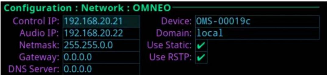
- Enter the Audio IP address used to transmit and receive audio across the network.

Notice!
The Audio IP address and the Control IP address should be in the same subnet. OMS displays a warning message if these addresses are not on the same subnet.
- Enter the Control IP address used by the OMNEO controller to access the network.
- Enter the Netmask address for the OMNEO interface.
- Enter the Gateway address for the OMNEO interface, if applicable.
- Enter the DNS Server address to which the OMNEO has access.
- Enter a recognizable device name for the OMNEO network connection.
- Enter the domain for the OMNEO network. By default, the domain is left blank.
- Select the Use Static check box to enable static IP addressing.

Notice!
If the Use Static check box is not selected, DHCP/Link-local is used and some of the remaining fields are automatically populated.
- Click the ENC1 encoder knob to exit.
A confirmation to save or discard changes appears. - Rotate the ENC2 encoder knob to the desired action.
- Click the ENC2 encoder knob to confirm.
8.4 Configure the RVON interface
To configure the RVON interface from the front panel, do the following:
- Navigate to the RVON icon.
- Click the ENC2 encoder knob.
The RVON Configuration screen displays.
Configuration: Network: RVON
IP Address: 192.168.0.20
Netmask:255.255.0.0
Gateway:0.0.0.0
- Enter the IP address of the RVON interface.
- Enter the Netmask address for the RVON interface.
- Enter the Gateway address for the RVON interface, if applicable.
- Click the ENC1 encoder knob to exit.
A confirmation to save or discard changes appears.
- Rotate the ENC2 encoder knob to the desired action.
- Click the ENC2 encoder knob to confirm.
9 Intercom configuration
9.1 Port configuration
9.1.1 Connect 2-Wire devices to OMS

Notice!
Applicable for Analog, Analog Plus, Intermediate, and Advanced models.
To connect a 2-Wire device to OMS, do the following:
- Navigate to the Configuration icon.
- Click the ENC2 encoder knob.
The Configuration menu displays.

- Navigate to the Ports icon.
- Click the ENC2 encoder knob.
The Ports menu displays.

- Navigate to the 2-Wire icon.
- Click the ENC2 encoder knob.
The 2-Wire Ports screen displays.

- Navigate to the Mode field.
- Click the ENC2 encoder knob.
The Mode field becomes active.
-
Select the desired mode.
-
Press the ENC2 encoder knob.
- Navigate to the Loop field. (Optional)
Modifications cannot be made to RTS 1 and RTS 2 modes.
- Click the ENC2 encoder knob.
The field is immediately toggled.
- Navigate to the Auto-Mute field. (Optional)
- Click the ENC2 encoder knob.
The field is immediately toggled.
- Click the ENC1 encoder knob to exit the screen.
A Changes Made confirmation message displays.

- Navigate to the desired action.

Notice!
Alternately, the ENC1 encoder knob can be clicked or the CLR button can be pressed to cancel this prompt and go back to editing the underlying screen.
- Click the ENC2 encoder knob to confirm the selection.
- Connect the 2-Wire device to the configured XLR connector on the rear panel of OMS.
9.1.2 Connect 4-wire analog devices to OMS

Notice!
Applicable for Analog Plus, Intermediate, and Advanced models.
To connect an 4-wire analog device to OMS, do the following:
- Connect the device to the AIO connector on the rear panel of OMS.
9.1.3 Connect OMNEO devices to OMS using Connect Devices

Notice!
Applicable for Analog Plus, Basic, Intermediate, and Advanced models.
To connect OMNEO devices to OMS using the Connect Devices menu, do the following:
- Navigate to the Configuration icon.
- Navigate to the Ports icon.
- Click the ENC2 encoder knob.
The Ports menu displays.
- Navigate to the Connect Devices icon.
- Click the ENC2 encoder knob.
OMS scans for available OMNEO devices, and then shows devices that support Easy Connect (KP-Series, DBP, OKI, etc.). Discoverable devices need to be powered on, connected to the network, and be on the same subnet.

- Navigate to the Connect All button.
OR
Navigate to the OMNEO device.

- Navigate to the Connect button.
- Click the ENC2 encoder knob.
The OMNEO devices or the selected OMNEO device connects to OMS.
9.1.4 Connect OMNEO devices to OMS

Notice!
Applicable for Analog Plus, Basic, Intermediate, and Advanced models.
To connect OMNEO devices to OMS, do the following:
- Navigate to the Configuration icon.
- Click the ENC2 encoder knob.
The Configuration menu displays.

- Navigate to the Ports icon.
- Click the ENC2 encoder knob.
The Ports menu displays.

- Navigate to the OMNEO icon.
- Click the ENC2 encoder knob.
The OMNEO Channels screen displays.

- Navigate to the Port field.
- Click the ENC2 encoder knob. The field becomes active.
- Scroll to the desired port.
- Click the ENC2 encoder knob. The field is changed.
- Navigate to the Device Name field.
- Click the ENC2 encoder knob. The field becomes active.
- Enter the device name of the partner device to connect to this port.
- Click the ENC2 encoder knob. The field turns yellow (modification made, but not confirmed).
- Navigate to the Device Type field.
- Click the ENC2 encoder knob. The field becomes active.
- Scroll to the OMNEO device type of the partner device.
- Click the ENC2 encoder knob. The field turns yellow (modification made, but not confirmed).
- Navigate to the channel field.
- Click the ENC2 encoder knob. The field becomes active.
- Scroll to the desired channel on the partner device.
- Click the ENC2 encoder knob. The field turns yellow (modification made, but not confirmed).
- (Optional) Enter a description for this connection.
- (Optional) Select the latency to use for this connection. (1 ms is recommended for best quality, except for DBP. DBP needs 2 ms latency).
- Click the ENC1 encoder knob to exit the screen. A Changes Made confirmation message displays.

Frame: 1
Port:16
Type: OMNI

Changes have been made:
Save
Discard
- Navigate to the desired action.
- Click the ENC2 encoder knob to confirm the selection.
9.1.5 Connect RVON devices to OMS

Notice!
Applicable for Advanced model only.
To connect RVON devices to OMS, do the following:
- Navigate to the Configuration icon.
-
Click the ENC2 encoder knob. The Configuration menu appears.
-
Navigate to the Ports icon.
-
Click the ENC2 encoder knob.
The Ports menu displays.
- Navigate to the RVON icon.
- Click the ENC2 encoder knob.
The RVON Channels screen displays.
| Configuration:Ports:RVON Channels | |||
| Port: | RVN1 | ||
| IP Address: | 169.120.0.17 | Codec: | G.711μ |
| Device Type: | RVON-KP | Packet Size: | 10 ms |
| Channel: | 1 | VAD: | -40 dBm |
| Description: | |||
- Navigate to the Port field.
- Click the ENC2 encoder knob.
The field becomes active.
- Scroll to the desired port.
- Click the ENC2 encoder knob.
The field is changed.
- Navigate to the IP Address field.
- Click the ENC2 encoder knob.
The field becomes active.
- Enter the IP Address of the partner device to connect to this port.
- Click the ENC2 encoder knob.
The field turns yellow (modification made, but not confirmed).
- Navigate to the Codec field.
- Click the ENC2 encoder knob.
The field becomes active.
- Select the codec to use.
- Click the ENC2 encoder knob.
The field turns yellow (modification made, but not confirmed).
- Navigate to the Device Type field.
- Click the ENC2 encoder knob.
The field becomes active.
- Scroll to the RVON device type of the partner device.
- Click the ENC2 encoder knob.
The field turns yellow (modification made, but not confirmed).
- Navigate to the Packet Size field.
- Click the ENC2 encoder knob.
The field becomes active.
- Select the packet size to use.
- Click the ENC2 encoder knob.
The field turns yellow (modification made, but not confirmed).
- Navigate to the channel field.
- Click the ENC2 encoder knob.
The field becomes active.
- Scroll to the Channel on the partner device.
- Click the ENC2 encoder knob.
The field turns yellow (modification made, but not confirmed).
- Navigate to the VAD field.
- Click the ENC2 encoder knob.
The field becomes active.
-
Select the VAD threshold level to use or to Off.
-
Click the ENC2 encoder knob.
The field turns yellow (modification made, but not confirmed).
-
(Optional) Enter a description for this port connection.
-
Click the ENC1 encoder knob to exit the screen.
A Changes Made confirmation message displays.

- Navigate to the desired action.
- Click the ENC2 encoder knob to confirm.

Notice!
Alternately, click the ENC1 encoder knob or press the CLR button to cancel this prompt and go back to editing on the underlying screen (for example, if the user is not ready to Save or Discard the modifications).
9.1.6 Add devices to the device catalog in IPedit

Notice!
Applicable for Analog Plus, Basic, Intermediate, and Advanced models.
To add an OMS to IPedit, do the following:
-
Open IPedit.
-
Select Add from the Device menu.
The Add Devices screen displays.

34 en | Intercom configuration OMS OMNEO Main Station

3. Select one or more available devices.
The Add button becomes active.
Notice!
OMS (OMNEO) and OMS-R (RVON) device types are shown as separate devices in IPedit. The OMNEO and RVON interfaces may be on the same network (in which case IPedit can talk to both devices at the same time) or, the network interfaces may be on separate networks (in which case, an IPedit session needs to be run on each network and each session sees either OMS or OMS-R, but not both), unless the PC has two network cards (one on each network) or the two networks are routable via a gateway.
4. Click the Add button.
The selected devices display in the device catalog.
5. Click the Done button.
The screen closes.
9.1.7 Configure an OMNEO channel for OMS using IPedit
Get the latest version of IPedit at http://www.rtsintercoms.com/.

Notice!
Applicable for Analog Plus, Basic, Intermediate, and Advanced models.
To configure OMS using IPedit, do the following:

Notice!
The Destination Type does not need to be selected if using the Browse window to select the device. It fills the type and IP Address automatically.
Using the Channel Configuration Pane
| OMNEO | Tie Lines | Channels 1-16 | Channels 17 |
| Channel 1 | |||
| Channel Configuration | |||
| Intercom Alpha | OMS : OM01 (N001) | ||
| Channel Description | |||
| Destination Type | OKP-2 | ||
| Destination Device Name | DIRECTOR | ... | |
| Destination IP Address | 192.168.3.24 | ||
| Destination Description | |||
| Destination Channel | Channel 1 | ||
| Destination Channel Description | |||
| Channel Input Gain | 0 dB | ||
- In the Destination Device Name field, click the ... button. The Discovered Devices screen displays.
- Expand the tree to view the destination devices available.
- Select the desired device for the destination.
- Click OK.
The screen closes.
- Select the channel to which the device connects.
- (Optional) Enter the channel description.
Using the Device Configuration Pane

- (Optional) Enter a description for the device.
- Send the changes to the device.
9.1.8 Configure an OMNEO device to connect to OMS

Notice!
Applicable for Basic, Intermediate, and Advanced models.
To configure an OMNEO device to accept a connection offer from an OMS, do the following:
- Navigate to the OMNEO Offers | Keypanel menu.
- Select an OMNEO device.
- Press the SEL button.
A list of available OMNEO connection offers display.
- Select the OMNEO connection to use.
An arrow displays next to the device. - Press CLR to exit menu mode.
9.1.9 Configure an RVON channel for OMS using IPedit

Notice!
Applicable for the Advanced model only.
To configure OMS RVON using IPedit, do the following:
- Select the OMS-R device from the Device Catalog.
Using the Channel Configuration Pane
- Select the destination device type.
- Enter the IP address of the destination device.
- Select the channel to which the device connects.
- Select the codec to use.
- Select the packet size to use.
- Enter the channel description. (Optional)
- Select the VAD check box. (Optional)
- (Optional) Enter a description for RVON.
- Send the changes to the device.
Using the Device Configuration Pane
9.1.10 Configure an RVON keypanel to connect to OMS

Notice!
Applicable for the Advanced model only.
To configure an RVON keypanel to accept a connection offer from an OMS, do the following:
- On the RVON keypanel, navigate to RVON Offers | Keypanel menu.
- Select the Matrix connection type.
- Press the SEL button.
A list of available RVON connection offers display.
- Select the RVON connection.
An arrow displays next to the connection.
- Press CLR to exit menu mode.
9.1.11 Configure OMNEO keypanels using IPedit

Notice!
Applicable to the Basic, Intermediate and Advanced models.
To configure OMNEO keypanel using IPedit, do the following: Using the Device Configuration Pane
![OMNEO Ethernet SNMP Authentication Configuration Device Name: DIRECTOR Domain: Description: Version: KP-5032, Version 2.5.0 [RSTP], Apr 6 2020, CRC=1ab4, FPc IP Address: 192.168.3.24 MAC: 00:1c:44:01:f2:4f Netmask: 255.255.0.0 Use Static IP Settings Gateway: 192.168.3.1 Use RSTP DNS Server: Enable AIO](/content/2026/06/1368847/images/8cbb6dda324873fd696b4333b131eb33793576f9a19f56dab36096c563f0e877.jpg)
- Enter a description for the device, if desired.
Using the Channel Configuration Pane
| OMNEO | Channels 1-2 | |
| Channel 1 | Channel 2 | |
| Channel Configuration | ||
| Intercom Alpha | OMS : OM01 (N001) | |
| Channel Description | ||
| Destination Type | OMS | OMI-16 |
| Destination Device Name | OMS ... | |
| Destination IP Address | 192.168.3.250 | - |
| Destination Description | ||
| Destination Channel | Channel 1 | Channel 1 |
| Destination Channel Description | ||
- Enter a channel description, if applicable.
- Select OMS from the destination type field.
| 3. Enter thename of the OMS deviceto which the channel will connect.ORClick the ...button.The Discovered Devices screen displays.4. Expand thetreeto view the destination devices available.5. Select thedesired devicefor the destination.6. ClickOK.The screen closes.7. Select thechannelto which the keypanel will connect. | |
 | Notice!If present, the Enable AIO check box must be cleared in order for the keypanel to connect via OMNEO. If this option is selected, the keypanel connects via AIO and the OMNEO link becomes an auxiliary Input/Output. |
| 8. Send thechangesto the device. | |
| 9.1.12 Configure RVON keypanels using IPeditTo configure RVON devices using IPedit, do the following:Using the Device Configuration Pane1. Enter adescription for the device, if desired.Using the Channel Configuration Pane1. Enter achannel description, if applicable.2. Select OMS-Rfrom the Destination Type drop down menu. | |
 | Notice!The Destination Type does not need to be selected if using the Browse window to select the device. It fills the type and IP Address automatically. |
| 3. Select thechannelto which the device connects.4. Select thecodecto use.5. Select thepacket sizeto use.6. Select theVAD check box. (Optional) | |
 | Notice!If present, the Enable AIO check box must be cleared in order for the keypanel to connect via OMNEO. If this option is selected, the keypanel connects via AIO and the OMNEO link becomes an auxiliary Input/Output. |
| 7. Send thechangesto the device. | |
10 Basic operation
10.1 Navigating the menu
The OMS menu structure separates into four logical sections: Status, Configuration, Intercom Setup, and Alarms. The menu is accessible using the keypad, the encoder knobs, or a combination of both.
MENU Home

Port Status

Menu

Form

| Keypad Character/Mode | MENU Home screen | Port Status Overview | Menu Form | (navigating) | Form (navigating) + SHIFT |
| 1/MUTE Go to STATUS menu | Go to STATUS menu | Go to STATUS menu | |||
| 2/UP Scroll info up | Scroll info up | Move to previous sibling menu | Move to previous field (up) | ||
| 3/ALL T Go to CONFIG menu | Go to CONFIG menu | Go to CONFIG menu | |||
| 4/LEFT Rotate icon highlight CCW | Move icon highlight left | Move to prev field (left) | |||
| 5/MENU Go to Link | Status Overview | Go to keypanel screen | Go to field (top/left) | ||
| 6/RIGHT Rotate icon highlight CW | Move icon highlight right | Move to next field (right) | |||
| 7/MICSEL Go to ALARM menu | Go to ALARM menu | Go to ALARM menu | Go to ALARM menu | ||
| 8/DOWN Scroll info down | Scroll info down | Move to next sibling menu | Move to next field (down) | ||
| 9/CWTLK Go to SETUP menu | Go to SETUP menu | Go to SETUP menu | |||
| 0/SHIFT Toggle SHIFT state | Toggle SHIFT state | Toggle SHIFT state | Toggle SHIFT state | ||
| */CLR Go to keypanel screen | Go to keypanel screen | Move up one menu level | Exit form (prompt if changes) | Exit form (abort changes) | |
| #/SEL Select | highlighted icon | Select highlighted icon | Initiate edit on selected field | Exit form (save changes) |
Tab. 10.14: Keypad operation when MENU is active
| Action / Mode H | Home Port Status | Overview | Menu Form | (navigating) | Form (navigating) + SHIFT |
| ENC1 (Left Encoder) | |||||
| Click Go to keypanel screen | Go to Link Status Overview | Move up one level | Exit form (prompt if changes) | ||
| Double-click Move top | Move to info top | Move up one level | Exit form (abort changes) | ||
| Press + Hold Activate screensaver | Activate screensaver | Activate screensaver | Activate screensaver | ||
| Rotate Scroll info | up / down | Scroll info up / down | Move to next / prev sibling | Scroll form up / down | |
| ENC2 (Right Encoder) | |||||
| Click Invoke | highlighted icon | Invoke highlighted icon | Initiate edit on selected field | ||
| Action / Mode Home Port Status | Overview | Menu Form (navigating) | Form (navigating) + SHIFT | |
| Double-click Go to | keypanel screen | Go up one level | Move up one menu level | Exit form (save changes) |
| Rotate Rotate icon highlight | Move icon highlight left / right | Move to next / prev field | ||
Tab. 10.15: Encoder knob operation
10.2 Editing field data
Throughout the front panel menu system are configuration forms. Forms can be viewed and modified using either the keypad, the encoder knobs, or a combination of both.
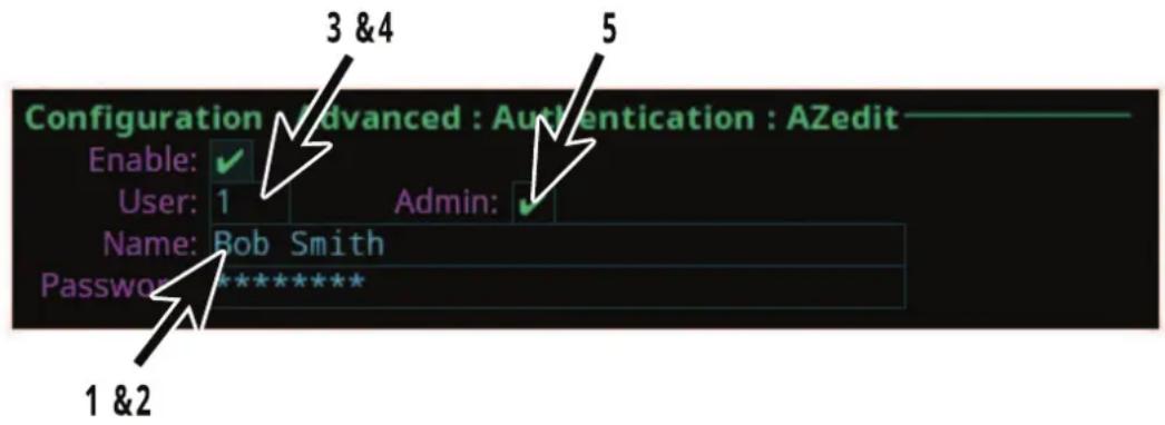
| Keypad Character / Mode | Field: Text 1 | Field+SHIFT: Text 2 | Field: Spinner 3 | Field: Pick List 4 | Field: Check Box 5 |
| 1/MUTE | |||||
| 2/UP Change | character at cursor | Insert new character at cursor | Increment value | Select next entry | Move to prev field (up) |
| 3/ALL T | |||||
| 4/LEFT Change | cursor location | Go to first character | Move to prev field (left) | ||
| 5/MENU Toggle | letter case | Toggle between start of digits, start of lower case letters, and start of upper case letters | Select minimum value | Select first entry | Go to first field (top/left) |
| 6/RIGHT Change | cursor location | Go to end of text | Move to next field (right) | ||
| 7/MICSEL | |||||
| 8/DOWN Change | character at cursor | Delete character | Decrement value | Select previous entry | Move to next field (down) |
| 9/CWTLK | |||||
| 0/SHIFT Toggle | SHIFT state | Toggle SHIFT state | Toggle SHIFT state | Toggle SHIFT state | Toggle SHIFT state |
| */CLR Backspace | (delete previous character and move backward) | Abort any changes | Abort changes | Abort changes | Exit form (prompt if changes) |
| #/SEL Accept | character at current location and move to the next character | Save changes | Save changes | Save changes | Toggle check state |
Tab. 10.16: Keypad operation when editing fields
- Press CLR to backspace if the cursor is not at the start of a field. At the start of a field, CLR deletes the character at the cursor.
- Pressing CLR when there is no text in the field; aborts the changes.
- Pressing UP / DOWN from the end of text (when the cursor is shown as an underline) starts the character offerings at the spot of the previous character (to the left). For example, if the previous character was an M, pressing UP / DOWN displays an N.
| Keypad Character / Mode | Form (editing): Text | Form (editing) + SHIFT: Text | Form (editing): Spinner | Form (editing): Pick List | Form: Check Box |
| Left Encoder | |||||
| Click Delete | character | Edit cancel (abort changes) | Edit cancel (abort changes) | Edit cancel (abort changes) | Exit form (prompt if changes) |
| Double-click Edit cancel (abort changes) | Edit cancel (abort changes) | Edit cancel (abort changes) | Edit cancel (abort changes) | Edit cancel (abort changes) | Exit form (abort changes) |
| Press + Hold Activate screensaver | Activate screensaver | Activate screensaver | Activate screensaver | Activate screensaver | |
| Rotate Move | character highlight | Move character highlight | Scroll form up / down | Scroll form up / down | Scroll form up / down |
| Right Encoder | |||||
| Click Move to the next character | Edit done (save changes) | Edit done (save changes) | Edit done (save changes) | Toggle check state | |
| Double-click Edit done (save changes) | Edit done (save changes) | Edit done (save changes) | Edit done (save changes) | Exit form (save changes) | |
| Rotate Changes current character | Toggle letter case (current character) | Change value Ch | change selected entry | Move to next / previous | |
Tab. 10.17: Shaft encoder operation
10.3 Local keypanel icons
The OMS local keypanel uses the following icons:
| Icon Icon Name Description | ||
 | Panel Mic Mute The panel mic is muted. | |
 | Panel Mic The panel mic is enabled. | |
 | Hot Mic The hot mic is active. Others can listen to the OMS local keypanel user even when no talk keys are on. | |
 | Headphone The headphones are enabled. | |
 | Headset Mic Mute The headset mic is muted. | |
 | Headset Speaker Mute | The headset speaker is muted. |
 | Headset The headset is enabled. | |
 | Panel Speaker Mute The panel speaker is muted. | |
 | Panel Speaker The panel speaker is enabled. | |
 | Tone 1 kHz Enabled Tone 1 kHz is enabled on the local keypanel. | |
 | Tone 500 Hz Enabled Tone 500 Hz is enabled on the local keypanel. | |
 | Virtual Key Talk and Listen Talk and listen are active on a virtual key row that is not currently visible. | |
 | Virtual Key Listen A listen key is active on a virtual key row that is not currently visible. | |
 | Virtual Key Talk A talk key is active on a virtual key row that is not currently visible. | |
 | Footswitch Active The footswitch is active. | |
 | Footswitch Enabled The footswitch is enabled, but not active.When a keypanel key is latched while the footswitch is enabled, the key tile turns amber to signify it is waiting for the footswitch. | |
 | All Call All Call is active. The icon displays as long as the key is pressed. | |
 | All Talk All Talk is active. The icon displays as long as the key is pressed. | |
 | Mic Kill Mic Kill is active. The icon displays for 3 seconds and then shuts off. | |
 | Stage Announce Stage Announce is active. The icon displays as long as the key is pressed. | |
 | Alarm An active alarm is present. | |
 | Key Row 1 Active The number in the icon indicates the active key row. | |
 | Key Row 2 Active The number in the icon indicates the active key row. | |
 | Key Row 3 Active The number in the icon indicates the active key row. | |
 | Key Row 4 Active The number in the icon indicates the active key row. | |
10.4 OMS menu icons and descriptions
Display panel icons

Notice!
Some menus are only visible depending on the OMS model.
| Icon Icon Name Description | |||||
 | Status Use the Status menu to view status information for the device. | ||||
 | System Use the System menu item to select the system status to view. See Status / System menu, page 78. | ||||
 | OMS Versions The OMS Versions menu item displays the version number for each OMS component (firmware or FPGA) currently installed on the device. See OMS version, page 78. | ||||
 | AZedit Sessions The AZedit Sessions menu displays the name (if available) and associated IP Address of each user connected to the frame via AZedit. See AZedit sessions, page 78. | ||||
 | IPedit Sessions The IPedit Sessions menu displays the name and associated IP Address of each user connected to the frame via IPedit. See IPedit sessions, page 79. | ||||
 | Size The Size menu displays the number of intercom resources available. See Size, page 79. | ||||
 | Network Use the Network menu item to select the network connection status to view. See Status / Network menu, page 81. | ||||
 | Control Port The Control Port menu item displays the status details for the Control Port. Control port, page 81. | ||||
 | OMNEO (SFP) The OMNEO (SFP) menu item displays the status details for the OMNEO SFP fiber ports. OMNEO (SFP), page 81. | ||||
 | OMNEO (RJ45) The OMNEO (RJ45) menu item displays status details for the OMNEO RJ45 ports. See OMNEO (RJ45), page 83. | ||||
 | RVON The RVON menu item displays status details for the RVON RJ45 port. See RVON, page 83. | ||||
 | Ports Use the Ports menu item to select the port type status to view. See Status / Ports menu, page 85. | ||||
 | OMNEO The OMNEO menu item displays status details for OMNEO ports. See OMNEO, page 85. | ||||
 | RVON The RVON menu item displays status details for RVON ports. See RVON, page 86. | ||||
 | AIO The AIO menu item displays status details for AIO ports. See AIO, page 87. | ||||
 | 2-Wire The 2-Wire menu item displays status details for 2-wire ports. 2-Wire, page 88. | ||||
 | Devices The Devices menu item displays status details for connected devices. See Devices, page 89. | ||||
 | TIF The TIF menu item displays status details for connected TIFs. See TIF, page 89. | ||||
 | Peripherals Use the Peripherals menu item to select the peripheral status to view. See Status / Peripherals menu, page 91. | ||||
 | GPIO-16 The GPIO menu item displays status details for any GPIO-16 connected to the device. See GPIO-16, page 91. | ||||
 | Intercom Use the Intercom menu item to select the type of intercom status to view. See Status / Intercom menu, page 92. | ||||
 | GPIO The GPIO menu items displays GPIO input and output states. See GPIO, page 92. | ||||
 | Crosspoint Inspect The Crosspoint Inspect menu item displays status of crosspoints for the selected input and output ports. See Crosspoint inspect, page 92. | ||||
| [YDSK] | Hardware Use the Hardware menu item to select the hardware status to view. See Status / Hardware menu, page 94. | ||||
 | Power Supplies The Power Supplies menu item displays the status information on the power in the device. See Power supplies, page 94. | ||||
 | Temperatures The Temperatures menu item displays status information of the temperature sensors in the device. See Temperatures, page 95. | ||||
 | Clock The Clock menu item displays the status of the system clock (PTP) for the device. See Clock, page 96. | ||||
 | Key Status The Key Status menu item displays the different key options configured on the keys. See Status / Key Status menu, page 97. | ||||
 | Configuration Use the Configuration menu for the initial configuration or reconfiguration of fundamental intercom settings (such as Intercom name, network configuration, port configuration, audio configuration, local keypanel configuration, user preferences, and authentication). | ||||
 | System Use the System | menu to set or change the device name. See Configuration / System menu, page 98. | |||
 | Intercom Name Use the | Intercom Name menu item to rename the intercom system. See Intercom name, page 98. | |||
 | Network Use the Network | menu to configure the network interfaces. See Configuration / Network menu, page 99. | |||
 | Control Port Use the Control Port menu item to configure the Ethernet network configuration for the Control Port. See Control port, page 99. | ||||
 | OMNEO Use the OMNEO | menu item to configure the Ethernet network configuration for the OMNEO Ports. See OMNEO, page 99. | |||
 | RVON Use the RVON | menu item to configure the Ethernet network configuration for the RVON. See RVON, page 100. | |||
 | Ports Use the Ports | menu to select the type of ports for configuration. See Configuration / Ports menu, page 102. | |||
 | Connect Devices Use the Connect Devices | menu item to discover and configure OMNEO device connections. See Connect Devices, page 102. | |||
 | OMNEO Channels Use the OMNEO Channels | menu item to configure connection parameters for the OMNEO channels. See OMNEO channels, page 103. | |||
 | RVON Channels Use the RVON | menu item to configure connection parameters for the RVON channels. See RVON channels, page 103. | |||
 | 2-Wire Ports Use the 2-Wire Ports menu item to configure the operating mode for the 2-wire ports. See 2-Wire ports, page 104. | |||
 | Audio Use the Audio menu to configure local audio settings.Configuration / Audio menu, page 106. | |||
 | Headset Mic/Speaker Use the Headset Mic/Speaker menu item configure headset settings. See Headset Mic / Speaker, page 106. | |||
 | Panel Mic/Speaker Use the Panel Mic/Speaker menu item to configure settings for the panel microphone or the panel speaker. See Panel mic / speaker, page 108. | |||
 | Filters Use the Filters menu item to add input and output bandpass filters or parametric equalization to the panel mic, headset mic, speaker and headset speaker. See Filters, page 110. | |||
 | Panel Mic Use the Panel Mic menu item to configure settings for the panel mic filters. See Panel mic, page 111. | |||
 | Headset Mic Use the Headset Mic menu item to configure settings for the headset mic filters. See Headset mic, page 112. | |||
 | Speaker Use the Speaker menu item to configure settings for the speaker filters. See Speaker, page 113. | |||
 | Headset Speaker Use the Headset Speaker menu item to configure settings for the headset speaker filters. See Headset Speaker, page 114. | |||
 | Mic Options Use the Mic Options menu item to configure the panel or headset microphone, such as the mic mute mode and the gain. See Mic options, page 115. | |||
 | Tone Generator Use the Tone Generator menu item to enable and configure the tone generator. The tone |
| generator checks the audio path from a device to the matrix. See Tone generator, page 115. | |||||
 | Key Volumes Use the Key Volumes menu item to adjust minimum crosspoint listen gains. See Key volumes, page 116. | ||||
 | Miscellaneous Use the Miscellaneous menu item to configure the reference level. See Miscellaneous, page 116. | ||||
 | Local Keypanel Use the Local Keypanel menu to configure many options that appear on the local keypanel, such as key options, auto dial assignments, panel swap options, page change options, call waiting window actions, footswitch actions, and display options. See Configuration / Local Keypanel menu, page 117. | ||||
 | Key Options Use the Key Options menu item to configure solo, exclusive and auto dial options. See Key options, page 117. | ||||
 | Auto Dial Use the Auto Dial menu item to assign auto dial numbers to available slots. See Auto dial, page 118. | ||||
 | Panel Swap Use the Panel Swap menu item to configure how the panel swap functionality works. See Panel Swap, page 119. | ||||
 | Page Change Use the Page Change menu item to configure different options associated with page change. See Page Change, page 119. | ||||
 | Call Waiting Window Use the Call Waiting Window menu item to configure how the CWW treats incoming calls. See Call waiting window, page 120. | ||||
 | Footswitch Use the Footswitch menu item to configure the footswitch actions. See Footswitch, page 120. | ||||
 | Display Options Use the Display Options menu item to configure panel volume and listen assignment displays. See Display Options, page 121. | ||||
 | User Preferences Use the User Preferences menu to configure device settings, such as front display and keypad brightness, screen saver setup, alpha size, keypad colors and operation. See Configuration / User Preferences menu, page 123. | ||||
 | Brightness Use the Brightness menu item to configure the brightness of the front panel LCD and the key brightness. See Brightness, page 123. | ||||
 | Screen Saver Use the Screen Saver menu item to modify screen saver settings and how the screen saver displays. See Screen saver, page 123. | ||||
 | Alpha Size Use the Alpha Size menu item to choose the number of characters in alphas. See Alpha size, page 124. | ||||
 | Keypad Use the Keypad menu item to configure the keypad settings (including LED colors and brightness for Keypad modes). See Keypad, page 124. | ||||
 | Options Use the Options menu item to configure various menu related options. See Options, page 125. | ||||
 | Keypad Hotkeys Use the Keypad Hotkeys menu item to enable or disable buttons on the front panel. See Keypad hotkeys, page 126. | ||||
 | Signaling Use the Signaling menu item to enable or disable call beeps. See Signaling, page 127. | ||||
 | Advanced Use the Advanced menu to select advanced configuration options to modify. See Configuration / Advanced menu, page 128. | ||||
 | Authentication Use the | Authentication menu item to select different areas of the OMS device to configure security. See Authentication menu, page 128. | |||
 | AZedit Use the AZedit | menu item to restrict access to AZedit. See AZedit, page 128. | |||
 | IPedit Use the IPedit | menu item to restrict access to IPedit. See IPedit, page 129. | |||
 | Front Panel Use the Front Panel | menu item to configure access restrictions for the front panel. See Front panel, page 129. | |||
 | Debug Shell Use the Debug Shell | menu item to access the debug shell authentication form. This form is used to restrict access to the debug shell. See Debug Shell, page 131. | |||
 | GPIO-16 Use the GPIO-16 | menu item to configure connections to GPIO-16 devices. See GPIO-16 menu, page 131. | |||
 | Clock Select Use the Clock Select | menu item to configure options for audio clock synchronization for OMNEO devices. See Clock Select, page 131. | |||
 | Soft Reset Use the Soft | Menu item to perform a soft reset on the frame. See Soft Reset, page 132. | |||
 | Diagnostics Use the Diagnostics | menu to select test panel mode. See Diagnostics, page 132. | |||
 | Test Panel Use the Test | Menu item to verify that all buttons, keys, and knobs on the front panel function properly. See Test Panel, page 132. | |||
 | Factory Reset Use the | Factory Reset menu item to reset the device to factory settings. By default, this icon is hidden. To display this icon, see Factory reset, page 67. | |||
 | Intercom Setup Use the | Intercom Setup menu to select the various intercom setup options such as resources, gains, and alphas. | |||
 | Party Line Membership | Use the Party Line Membership menu item to add and remove party line memberships. See Intercom setup / Party line membership, page 134. | |||
 | Stored Setups Use the | Stored Setups menu to select the slot folder to store, modify, or delete intercom setup files. See Intercom setup / Stored Setups menu, page 137. | |||
 | Stored Setup Slot Folders | Use the Store Setup Slot Folders to store, modify, or delete intercom setup files.Configure and save up to four setup (slots) in OMS. | |||
 | |||||
 | |||||
 | |||||
 | Devices Use the Devices | menu to select the various setup options such as Key Assignments, Setup Pages, and Scroll Enables. See Intercom setup / Devices menu, page 140. | |||
 | Key Assignments Use the | Key Assignments menu to set up key assignments on keypanel keys. See Key assignments, page 140. | |||
 | Setup Pages Use the | Setup Pages menu item to set up additional pages on a keypanel port. See Setup pages, page 141. |
 | Scroll Enables Use the Scroll Enables menu item to set up scroll enables and latch disables. See Scroll enables, page 142. | |||
 | Resources Use the Resources menu item to select the assignment type to configure. See Intercom setup / Resources menu, page 144. | |||
 | Party Line Use the Party Line menu item to define party lines in the intercom system. See Party line, page 144. | |||
 | IFB Use the IFB menu item to configure IFBs. See IFB, page 145. | |||
 | Special List Use the Special Lists menu item to configure special lists. See Special list, page 147. | |||
 | Relay Use the Relay menu item to configure a relay. See Relay, page 148. | |||
 | ISO Use the ISO menu item to configure ISOs. See ISO, page 148. | |||
 | Gains Use the Gains menu to select the type of gain modification to make. See Intercom setup / Gains menu, page 150. | |||
 | I/O Use the I/O menu item to set input and output gains for different ports. See I/O, page 150. | |||
 | Crosspoint Use the Crosspoint menu item to set crosspoint gains in the system. See Crosspoint, page 151. | |||
 | Party Line Use the Party Line menu item to set Party Line gains in the system. See Party line, page 151. | |||
 | Alphas Use the Alphas menu to select the type of alpha assignment. See Intercom Setup / Alphas menu, page 153. |
 | Port Use the Port menu | item to view and edit the Alphas for each port assignment. | |||
 | Party Line Use the Party | Line menu item to view and edit the Alphas for each party line assignment. | |||
 | IFB Use the IFB menu item | to view and edit the Alphas for each IFB assignment. | |||
 | Special List Use the Special List menu item to view and edit the Alphas for each special list assignment. | ||||
 | Relay Use the Relay menu item to view and edit the Alphas for each relay assignment. | ||||
 | ISO Use the ISO menu item to view and edit the Alphas for each ISO assignment. | ||||
 | Alarms Use the Alarms menu to access alarm notifications of events that occur in the intercom system. If the sound waves in the icon flash, there are unacknowledged alarms in the system. | ||||
 | Unacknowledged The Unacknowledged menu item displays alarms the user has not yet acknowledged. See Alarms / Unacknowledged, page 155. | ||||
 | Active The Active menu item displays all alarms that have occurred and are still active (for example, the fault has not gone away). See Alarms / Active, page 156. | ||||
Refer to
- Factory reset, page 67
- Status | System menu, page 78
- OMS version, page 78
- AZedit sessions, page 78
- IPedit sessions, page 79
- Size, page 79
- Status / Network menu, page 81
- Control port, page 81
- OMNEO (SFP), page 81
-
OMNEO (RJ45), page 83
-
RVON, page 83
- Status | Ports menu, page 85
- OMNEO, page 85
- RVON, page 86
- AIO, page 87
- 2-Wire, page 88
- Devices, page 89
- TIF, page 89
- Status | Peripherals menu, page 91
- GPIO-16, page 91
- Status | Intercom menu, page 92
- GPIO, page 92
- Crosspoint inspect, page 92
- Status | Hardware menu, page 94
– Power supplies, page 94 - Temperatures, page 95
- Clock, page 96
- Status | Key Status menu, page 97
- Configuration | System menu, page 98
- Intercom name, page 98
- Configuration | Network menu, page 99
- Control port, page 99
- OMNEO, page 99
- RVON, page 100
- Configuration | Ports menu, page 102
- Connect Devices, page 102
- OMNEO channels, page 103
- RVON channels, page 103
- 2-Wire ports, page 104
- Configuration | Audio menu, page 106
- Headset Mic / Speaker, page 106
- Panel mic / speaker, page 108
- Filters, page 110
- Panel mic, page 111
- Headset mic, page 112
- Speaker, page 113
- Headset Speaker, page 114
- Mic options, page 115
- Tone generator, page 115
- Key volumes, page 116
- Miscellaneous, page 116
- Configuration | Local Keypanel menu, page 117
- Key options, page 117
- Auto dial, page 118
- Panel Swap, page 119
- Page Change, page 119
- Call waiting window, page 120
- Footswitch, page 120
-
Display Options, page 121
-
Configuration | User Preferences menu, page 123
- Brightness, page 123
- Screen saver, page 123
- Alpha size, page 124
- Keypad, page 124
- Options, page 125
- Keypad hotkeys, page 126
- Signaling, page 127
- Configuration | Advanced menu, page 128
- Authentication menu, page 128
- GPIO-16 menu, page 131
- AZedit, page 128
- IPedit, page 129
- Front panel, page 129
- Debug Shell, page 131
- Clock Select, page 131
- Soft Reset, page 132
– Diagnostics, page 132 - Test Panel, page 132
- Intercom setup | Party line membership, page 134
- Intercom setup | Stored Setups menu, page 137
- Intercom setup | Devices menu, page 140
- Key assignments, page 140
- Setup pages, page 141
- Scroll enables, page 142
- Intercom setup | Resources menu, page 144
- Party line, page 144
- IFB, page 145
- Special list, page 147
- Relay, page 148
- ISO, page 148
- Intercom setup | Gains menu, page 150
- I/O, page 150
- Crosspoint, page 151
- Party line, page 151
- Intercom Setup | Alphas menu, page 153
- Alarms menu, page 155
– Alarms | Unacknowledged, page 155 - Alarms | Active, page 156
10.5 Port status overview
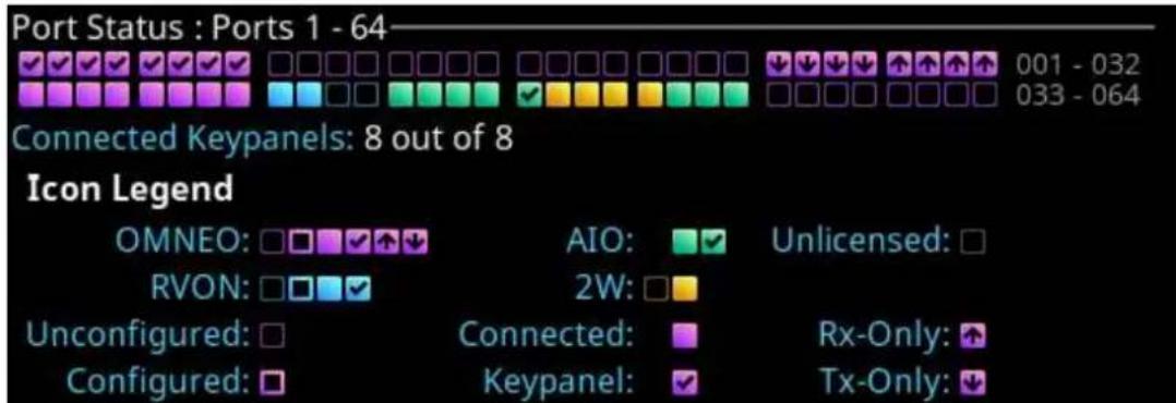
The Port Status Overview displays the status of all the ports in the frame. Different colored status boxes represent the different port types and port statuses.
To display the port status screen, do the following:
- Press the SHIFT+INFO button on the keypad.
The Port Status screen displays.
bar
| Port Status | Ports 1 - 64 | Connected Keypanels: 8 out of 8 | | :--- | :--- | :--- | | ✓✓✓✓✓✓✓✓✓✓✓✓✓✓✓✓✓✓✓✓✓✓✓✓✓✓✓✓✓✓✓✓✓✓✓✓✓✓✓✓✓✓✓✓✓✓✓✓✓✓✓✓✓✓✓✓✓✓✓✓✓✓✓✓✓✓✓✓✓✓✓✓✓✓✓✓✓✓✓✓✓✓✓✓✓✓✓✓✓✓✓✓✓✓✓✓✓✓✓✓✓ ✓ ✓ ✓ ✓ ✓ ✓ ✓ ✓ ✓ ✓ ✓ ✓ ✓ ✓ ✓ ✓ ✓ ✓ ✓ ✓ ✓ ✓ ✓ ✓ ✓ ✓ ✓ ✓ ✓ ✓ ✓ ✓ ✓ ✓ ✓ ✓ ✓ ✓ ✓ ✓ ✓ ✓ ✓ ✓ ✓ ✓ ✓ ✓ ✓ ✓ ✓ ✓ ✓ ✓ ✓ ✓ ✓ ✓ ✓ ✓ ✓ ✓ ✓ ✓ ✓ ✓ ✓ ✓ ✓ ✓ ✓ ✓ ✓ ✓ ✓ ✓ ✓ ✓ ✓ ✓ ✓ ✓ ✓ ✓ ✓ ✓ ✓ ✓ ✓ ✓ ✓ ✓ ✓ ✓ ✓ ✓ ✓ ✓ ✓ ✓ 001 - 032 033 - 064 Icon Legend OMNEO: □□□□□□□□□□□□□□□□□□□□□□□□□□□□□□□□□□□□□□□□□□□□□□□□□□□□□□□□□□□□□□□□□□○ RVON: □□□□✓✓ Unconfigured: □ Configured: □ AIO: 2W: Connected: Keypanel: Unlicensed: Rx-Only: Tx-Only: An icon legend| Color Description | |
| Blue RVON | |
| Green AIO | |
| Gold 2-Wire | |
| Magenta OMNEO | |
| Grey Port not licensed |
| Icon Description | |
| Not configured (displayed as a square outline in the Port Type color) | |
| Configured, not connected | |
| Configured, connected, bi-directional audio | |
| Configured, connected, keypanel attached and communicating | |
| Configured, connected, OMNEO unidirectional receive | |
| Configured, connected, OMNEO unidirectional transmit | |
| Port is unlicensed (grey square outline) |
10.6 Link status overview
The Link Status Overview screen displays the different system connections available on the device. The different color LEDs represent the different connection statuses.

Figure 10.1: Link Status Overview Screen
Ethernet Links
The Ethernet Links section shows link status for the CTRL, RVON, and OMNEO (4) interfaces.
| GREEN LED RED LED GREY LED | |||
| CONTROL RVON | The link is up. The Control or RVON IP Address is specified, but none of the links are up (for RJ45). The LED is red when and IP address is defined, but there is no link. | The LED is grey when no IP address (Control or Audio) is specified but at least one of the other links is up. | |
| OMNEO The status indicators are displayed to mimic the back panel | |||
| The link is up. The Audio and /or Control interfaces have an IP Address but none of the four links are up. OR An SFP is installed and there is no link. | At least one OMNEO link is up. OR No SFP is installed. | ||
Miscellaneous
The Miscellaneous section contains additional status information for Alarms, AZedit sessions, IPedit sessions, and PTP clock status.
| Alarms X/Y is shown | where X is the number of unacknowledged alarms and where Y is the total number of active alarms.- When shown in red, X is greater than 0- When shown in yellow, X is equal to 0 and Y is greater than 0- When shown in green, X and Y are equal to 0 |
| AZedit The number | of active AZedit sessions.- When shown in green, there is at least one AZedit connection- When shown in yellow, there are no AZedit connections |
| IPedit The number | of active IPedit sessions.- When shown in green, there is at least one IPedit connection- When shown in yellow, there are no IPedit connections |
| CLK The status of | the OMNEO PTP clock.- When a green LED is displayed, the PTP clock is linked- When a red LED is displayed, the PTP clock is not linked |
10.7 Page change
The Page button provides access to different setup pages on the device. Setup pages provide a quick method to reconfigure key assignments. There are four setup pages.

Figure 10.2: Page Change
To change the page from the front panel, do the following:
- Press the SHIFT button.
- Press the PAGE button.
The configured page tabs appear in the front panel display.
- Press the arrow buttons to navigate to the desired page.
- Press the SEL button.
The page changes.
To remove a setup page assignment, do the following:
- Press the SHIFT button.
- Press the PAGE button.
The configured page tabs appear in the front panel display.
- Press the arrow buttons to navigate to the desired page.
- Press the SHIFT button.
- Press CLR.
10.8 Party Line Call window
The Party Line Call window keeps a history of party line callers and displays them in a scrollable graphical window. Three party line calls display in the window with a scroll arrow that appears if there are more than three calls in the list.

Figure 10.3: Party Line Call window
To display the party line call window, do the following:
▶ Click the ENC 2 encoder knob.
The party line window opens with the most recent call at the top of the list.
To hide the party line call window, do the following:
▶ Click the ENC 2 encoder knob.
The party line call window closes.

Notice!
If the party line window is visible and not empty, the window remains visible until the user hides it. If the party line window is visible, but empty, the window auto-hides after a five-second timeout.
Incoming Calls
When a call comes into the OMS front panel, the party line call window appears on the display. The party line window retains the call history for up to 16 calls. The most recent call inserts at the top of the graphical list and is highlighted. Other items in the list shift down, as necessary.
Call assignments in the list have a color code assigned to them.
The color representations are:
| Color Description | |
| Dark blue Non-selected call | |
| Light blue Selected call (not talking) | |
| Green Selected call (talking) |
To scroll the party line call list, do the following:
When the party line call list is visible, rotate the ENC2 encoder knob to move through the scroll list.
To answer a call on the party line call list, do the following:
- Scroll to the call.
- Press and hold the CWTLK button.

- Release the CWTLK button to stop talking.
To clear the party line call list, do the following:
- Select the party line call to clear from the list.
- Press the SHIFT button.
- Press the CWCL button.
10.9 Call waiting window
The Call Waiting Window feature can keep a history of the last nine point-to-point callers and display them in a scrollable, graphical window. The CWW (Call Waiting Window) displays three point-to-point calls at a time with a scroll arrow appearing if there are more than three calls in the list.

Figure 10.4: Call Waiting Window
To display the CWW, do the following:
- Press the SHIFT button.
- Press the CWCL button.
The CWW window appears on the front panel display.
To hide the CWW, do the following:
▶ Press the CLR button.
The CWW window closes.

Notice!
If the CWW list is visible and not empty, it remains visible until hidden. If the CWW list is visible, but empty, it auto-hides after a five-second timeout.
Incoming Calls
When a call comes into the keypanel, the graphical CWW list appears on the keypanel display. The CWW retains call history for up to nine calls. The most recent call inserts at the top of the graphical CWW list and is highlighted. Other items in the CWW list shift down, as necessary. When a new call arrives, the last call in the list drops, unless it is highlighted in the graphical CWW. In this case, it cannot shift off the CWW list.
Call assignments in the CWW list have a color code assigned to them.
The color representations are:
| Color Description | |
| Dark blue New call | |
| Light blue Selected call (not talking) | |
| Green Selected call (talking) | |
| Very dark blue Old call |
To scroll the CWW list, do the following:
When the CWW list is visible, press the arrow up or the arrow down button. The highlight moves through the scroll list.
To answer a call on the CWW, do the following:
- Scroll to the call.
- Press and hold the CWTLK button.
- Release the CWTLK button to stop talking.
10.10 UPG
A UPG (User Programmable Button) gives the user the option to assign a panel swap to the UPG button on the keypad, eliminating the need to navigate through the menu structure to swap to a different panel (i.e., EKP).
To assign the UPG key, do the following:
- Click the MENU key.
- Navigate to the Configuration menu.
- Click the ENC2 encoder knob.
- Navigate to Local Keypanel.
- Click the ENC2 encoder knob.
- Navigate to Panel Swap.
- Click the ENC2 encoder knob.
- Verify the # of EKPs is more than 0.
- Navigate to the Keypad UPG field.
- Click the ENC2 encoder knob.
- Turn the ENC2 encoder knob to scroll through options.
- Click the ENC2 encoder knob to confirm the selection.
- Click the ENC1 to exit the menu.
10.11 Mic kill
Mic Kill is an inaudible signal sent by the OMS that forces all devices on the affected party line to stop talking. This feature is useful when an unattended microphone is left in the position and is causing unnecessary noise on the line. The mic kill keypad hotkey is enabled, by default. Mic kill does not affect the OMS local keypanel or any attached keypanel (like KP-Series and ROAMEO beltpacks). Mic kill does affect digital party line devices, analog party line devices, and OMS tie lines.
| The mic kill function does not work on Clear-Com analog beltpacks.For information on disabling mic kill, please reference Keypad hotkeys, page 126.To use mic kill, do the following:1. Enable the Party Line Talk button on the party line intended to receive the mic kill signal. | |
 | Notice!Press multiple PL talk keys to send a signal to multiple party lines. |
| 2. Press the SHIFT button.3. Press the MKILL button.A mic kill icon appears in the panel display.Mic Kill AllA Mic Kill All executes the mic kill command for all party lines on any of the OMS keys (including virtual keys). For a mic kill all, the talk button does not need to be enabled.To use mic kill all, do the following:1. Enable the Party Line Talk button on the party line intended to receive the mic kill signal. | |
 | Notice!Press multiple PL talk keys to send a signal to multiple party lines. |
- Press the SHIFT button.
- Press the MKILL button.
A mic kill icon appears in the panel display.
- Press the SHIFT button.
- Press the ALL T button within three seconds.
Refer to
- Keypad hotkeys, page 126
10.12 Info button
The INFO button provides basic information on OMS such as Port Status and Link Status.
For more information on Port Status, please reference Port status overview, page 58.
For more information on Link Status, please reference Link status overview, page 59.
To display INFO, do the following:
- Press the SHIFT button.
- Press the INFO button. The screen shows Port Status.
- Press the INFO button. The screen shows Link Status.
- Press CLR to exit.
Refer to
- Port status overview, page 58
- Link status overview, page 59
10.13 All call
The ALL CALL button sends a call signal to party lines that are assigned to the OMS keys, including virtual keys not currently visible on the front panel. For devices connected to the OMS, ALL CALL causes an incoming call notification to the local user by a combination of visual, audio, or haptic notification. In this instance, ROAMEO beltpacks act as keypanels, with the notification being a flashing alpha or other configurable behaviors.
For partyline devices connected to OMS, pushing the ALL CALL button sends a notification to every device that is a member of the called party lines. For example, an OMS operator pushes the ALL CALL button prior to ALL TALK. The ALL CALL would serve as an alert to beltpack operators to put on their headsets and force the listen function on user stations so the user can hear the ALL TALK message.
For more information, please reference All talk, page 65.
To use ALL CALL, do the following:
-
Press the SHIFT button.
-
Press the ALL C button.
The listen indicators activate on all partyline assignments.
- Release ALL C button, the call ceases.
Refer to
- All talk, page 65
10.14 All talk
The ALL T button activates the talk button on every OMS partyline assignment visible and virtual. ALL TALK is a momentary function only active when the user pushes the ALL T button. The user can use ALL TALK singularly or in conjunction with the ALL CALL feature.
ALL TALK connects the panel microphone or headset microphone audio of the OMS to party lines assigned to the OMS front panel, including party lines assigned to virtual keys not currently visible. This can include 2W analog beltpacks, digital beltpacks, ROAMEO beltpacks, keypanels, and tie line audio.
It is common to use ALL TALK in-line with ALL CALL.
For more information, please refer to All call, page 65.
To use ALL TALK, do the following:
- Press the ALL T button.
Begin speaking.
- Release the ALL T button to end transmission.
Refer to
- All call, page 65
10.15 Key assignment mode
Use Key Assignment Mode to display a scrollable list on the specific key. Key assignment allows the user to quickly change key assignments without entering a menu.
When a key is first put into Assignment mode, by default the key shows assignments available for the existing key assignment type. Press the left or right arrow on the keypad changes the assignment type, which allows the user to change the assignment type of the key.
The circles located at the bottom of each key signifies the number of lists available. The dark circle indicates the location of the list relative to the number of lists available.

Figure 10.5: Assignment Selection Mode

Notice!
Use the key volume encoder knob associated with the key assignment to change the assignment on a specific key. For example, to change key 1, operate key volume encoder knob 1, to change key 2, operate key volume encoder knob 2, and so on.
To modify the key assignment using key assignment mode, do the following:
- Press and hold or double-click the key volume knob until a scrollable list appears on the front panel display.
- Turn the encoder knob to navigate to the key assignment.
- Click the encoder knob to confirm the selection.
To change the key assignment type using key assignment mode, do the following:
- Press and hold or double-click the key volume knob until a scrollable list appears on the front panel display.
- Press the right or left arrow button on the keypad.
- Turn the encoder knob to navigate to the key assignment.
- Click the encoder knob to confirm the selection.
To delete the key assignment, do the following:
- Press and hold or double-click the key volume knob until a scrollable list appears on the front panel display.
- Press the right or left arrow button on the keypad until the unassigned assignment displays.
- Click the encoder knob to confirm the selection.
10.16 SA keypad button
The SA keypad button, also known as Stage Announce, allows the OMS front panel user to make an announcement over a public address system. When the SA button is pressed, the active microphone audio is routed to the stage announce output port and removed from all other existing mixes for the duration the key is pressed.
The function of this key is set as momentary operation. This means that when the user presses the key, the function is active, and when the key is released, the device goes back to normal operation.
The SA key can never be set to latch on.
Other devices in the system can also perform a stage announce by assigning the SA special function key assignment to one of the device's keys. The SA key assignment operation in the same manner as the OMS SA keypad button.
To send an announcement using the SA button, do the following:
- Press the SHIFT button.
- Press and hold the SA button to make the announcement.
- Release the SA button when done making the announcement.
10.17 RSTP
RSTP (Rapid Spanning Tree Protocol) is a fault tolerant Ethernet protocol, which allows the system to be set up with multiple Ethernet connection paths to the same access points. This provides a redundant connection if one connection path fails. The RSTP connection paths prevent the possibility of packets getting into an infinite loop.
RSTP is an IEEE standardized network protocol (802.1w) ensuring a loop-free topology for an Ethernet LAN (Local Area Network), evolved from STP (Spanning Tree Protocol). OMNEO fully supports RSTP IEEE802.1w. When using switches that support this technology, it is necessary to adjust the RSTP parameters of the switch according to the following:
Hello Time: 9 seconds
Maximum Age: 22 seconds
Forward Delay: 30 seconds
This is supported by the major switch brands.
10.18 Factory reset
Use the Factory Reset menu to set the device back to its original factory settings. The icon for the factory reset menu is hidden by default.
To display the factory reset icon in the menu structure, do the following:
▶ Press and hold the ENC 1 and ENC 2 encoder knobs when powering on the device. Release the encoder knobs when the splash screen appears.
To perform a factory reset, do the following:
-
Navigate to the Configuration menu.
-
Click the ENC2 encoder knob.
-
Navigate to Advanced.
-
Click the ENC2 encoder knob.
-
Navigate to Factory Reset.
-
Click the ENC2 encoder knob.
The Factory Reset confirmation message appears.
-
Navigate to Do Reset.
-
Click the ENC2 encoder knob.
A countdown message gives direction to press the MENU key on the keypad 5 times.


Press MENU 5 times to confirm...
- Press the MENU key five times.
The device reboots.
10.19 Front panel reset button
Use the front panel reset button to reset the device without having to unplug the device. Use this function when the device is unresponsive. For example, if the keypad is not working properly and the menu system is inaccessible.
Refer to the OMS reference view, page 12 for the front panel reset opening position.
To use the front panel reset button, do the following:
-
Insert a straightened paperclip into the front panel reset opening.
-
Push the paperclip until the switch clicks.
The device resets.
Refer to
- OMS reference view, page 12
11 Download firmware
11.1 Download firmware using AZedit
To download firmware to the device, do the following:
- Open AZedit.
-
Select Software Versions | Master Controllers from the Status menu. The Master Controller Version Information screen displays.
-
Highlight the device to be updated.
-
Right-click the highlighted selection.
A popup menu displays.
![AZedit - [ONLINE] - Master Controller Version Information File Online Authentication Edit View System Alphas Status Options Help File Online Authentication Edit View System Alphas Status Options Help MC / Version 001 OMNEO Main Station, Version 0.2.2, Feb 24 2020, FPGA Download firmware... Download splash screen... Download screen saver... Download license...](/content/2026/06/1368847/images/d0d6db614f07e25f285fa4319b8ee804cd342d97f9fa2b4a173473e385b59f68.jpg)
- Select Download firmware...
The Firmware Download screen displays. -
Use the browse button to navigate to the firmware file.
-
Click Open. The Download Device Firmware screen displays.

8. Click Begin Download.
The download begins. Once the image loads, a success message displays.

9. Click OK.
The screen closes.
10. Verify the firmware version is correct in the Master Controller Version Information screen.
The flash programming progression status shows on the front panel of the device.


Notice!
The firmware.mot file contains four different components - Main firmware, main FPGA, LEC firmware, and Bootloader - that programs each one after the other. Multiple progression bars display.
11.2 Download firmware using Firmware Upload Tool
The Audio FPGA can only be upgraded using the Firmware Upload Tool.

Notice!
The firmware.capfw file includes all the components contained in the .mot file, plus the Audio FPGA.
Required firmware version:
- FWUT V5.4.0 and above
To download firmware to the device, do the following:
-
Open the Firmware Upload Tool.
-
Select Options from the File menu.
The Firmware Upload Tool Options window displays.

3. Click Change.
A network folder screen displays.
-
Navigate to the folder containing the firmware files.
-
Click OK.
-
Click OK.
The screen closes.
- Select the device to update from the Device page.
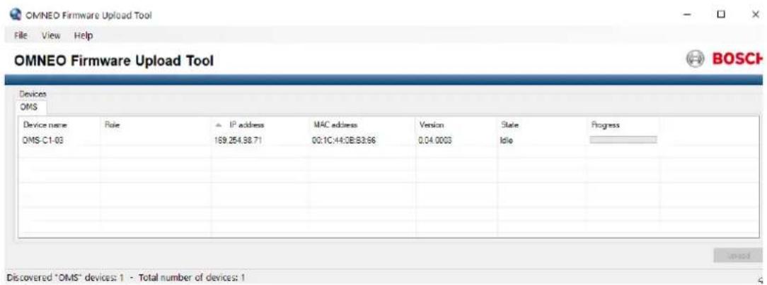
8. Click Upload.
The Select Firmware for Upload screen displays.

9. Select the firmware to download.
10. Click Start.
The Firmware Upload Tool main screen displays. A progression bar is available to track the firmware download progress. The device reboots automatically when all the firmware is updated.

11.3 Download splash screen
To download a splash screen image to the device, do the following:
- Open AZedit.
- Select Software Versions | Master Controllers from the Status menu. The Master Controller Version Information screen displays.
- Highlight the device to be updated.
- Right-click the highlighted selection.
A popup menu displays.
![AZedit - [ONLINE] - Master Controller Version Information File Online Authentication Edit View System Alphas Status Options Help MC / Version 001 OMNEO Main Station Advanced, Version 0.3 (F:\12\2007\MS\1-1-1\MAC=00 Download firmware... Download splash screen... Download screen saver... Download license...](/content/2026/06/1368847/images/2f2455df41fc03bbb6c0e792a05e345cd5c44f1c9ad36c00c9b33a834932c507.jpg)
- Select Download splash screen...
The network folder opens.
-
Navigate to the desired file.
-
Click Open.
The Download Splash Screen File screen opens.

8. Click Begin Download.
The download begins. A progression bar appears to show the progress of the download. Once complete, a success message shows.

9. Click OK.
The message closes. The file is updated.
11.4 Download screen saver
To download a screen saver image to the device, do the following:
- Open AZedit.
-
Select Software Versions | Master Controllers from the Status menu. The Master Controller Version Information screen displays.
-
Highlight the device to be updated.
-
Right-click the highlighted selections.
A popup menu displays.
![AZedit - [ONLINE] - Master Controller Version Information File Online Authentication Edit View System Alphas Status Options Help File Online Authentication Edit View System Alphas Status Opti MC / Version 001 OMNEO Main Station, Version 0.2.2 Feb 24-2020 EPGA 1.1.1 MAC=00:0b:7c:ff:ff:c0 Download firmware... Download splash screen... Download screen saver... Download license...](/content/2026/06/1368847/images/adea5d3fd89bb172075ebd78e4a2c5529bcca867031587a6318070ce2769b7b3.jpg)
- Select Download screen saver...
The network folder opens.
-
Navigate to the desired file.
-
Click Open.
The Download Screen Saver File screen opens.

8. Click Begin Download.
The download begins. A progression bar appears to show the progress of the download. Once complete, a success message shows.

1. Click OK.
The message closes. The file is updated.
11.5 Download licenses
To download licenses to the device, do the following:
- Open AZedit.
- Select Software Versions | Master Controllers from the Status menu. The Master Controller Version Information screen displays.
- Highlight the device to be updated.
- Right-click the highlighted selections. A popup menu displays.
![AZedit - [ONLINE] - Master Controller Version Information File Online Authentication Edit View System Alphas Status Options Help File Online Authentication Edit View System Alphas Status MC / Version 001 OMNEO Main Station, Version 0.2.2 Feb 24-2020 EPGA 1.1.1 MAC-00:0b:7c:ff:ff:c0 Download firmware... Download splash screen... Download screen saver... Download license...](/content/2026/06/1368847/images/63dc82be418da0334fe12dfb42b99bdb8cc3cc00b1329e120cd73890a4c1b50f.jpg)
- Select Download license...
The network folder opens.
-
Navigate to the desired file.
-
Click Open.
The Download License File screen opens.

Figure 11.1:
- Click Begin Download.
The download begins. A progression bar appears to show the progress of the download. Once complete, a success message shows.
AZedit

AZedit has successfully completed sending the file. However, it may still be being delivered to the target device(s).
Please use the Software Version screens to verify the success of the download before removing or re-powering the target device(s).

1. Click OK.
The message closes. The license is applied.
12 Main menu access
The Home Screen is the top-most level of the menu structure.

Figure 12.1: OMS Menu Home
Available selections for this menu are:

Status Menu

Configuration Menu

Intercom Setup Menu

Alarm Menu
For more information on the menu structure, refer to OMS menu icons and descriptions, page 46.

Notice!
For detailed instructions on using the front panel controls, see Navigating the menu and Editing form data.
To access the main menu structure, do the following:
- Navigate to the desired menu.
- Click the ENC2 encoder knob to access the selected menu.
To access the main menu structure when at the keypanel screen, do the following:
▶ Press the MENU button.
13 Status | System menu
Use the Status menu to view status information related to system, network, ports, peripherals, intercom, hardware, and key status.

Figure 13.1: Status Menu
System menu
The System menu contains information about the firmware used in OMS, AZedit/IPedit sessions, and the intercom size.

Figure 13.2: Status : System
13.1 OMS version
The OMS Versions screen displays the current versions for each firmware component in the system and the current licensed model.

Notice!
If RVON is not supported on OMS, then LEC (Line Echo Canceller) Application displays.
| Status : System : OMS Versions | |
| Main Application: | 0.1.8 |
| LEC Application: | 0.0.8 |
| Bootloader: | 0.0.2 |
| Main FPGA: | 1.1.0 |
| Audio FPGA: | 5.40.5418 |
| Model: | Intermediate |
Figure 13.3: Status | System | OMS Versions Screen
13.2 AZedit sessions
The AZedit Sessions screen displays the user name (login name), if applicable, and network connection of each AZedit session connected to the device.

Figure 13.4: Status | System | AZedit Sessions Screen
Name Field
The Name field displays the authenticated user name of the user connected. A login name is only required if authentication is enabled.
Connection Field
The Connection field displays the IP address of the computer running AZedit.
13.3 IPedit sessions
The IPedit Sessions screen displays the user name (login name) and network connection (OMNEO or RVON Interface) of each IPedit session connected to the device.

Figure 13.5: Status | System | IPedit Sessions Screen
Name Field
The Name field displays the authenticated user name of the user connected. A login name is only required if authentication is enabled.
Connection Field
The Connection field displays the IP address of the computer running IPedit and displays whether the session is communicating on the OMNEO or RVON Port.
13.4 Size
| Ports: 64 Party Lines: 16 IFBs: 16 Special Lists: 16 ISOs: 16 | GPI Outputs: 64 GPI Inputs: 64 UPL Statements: 256 UPL Resources: 120 |
Figure 13.6: Status | System | Size Screen
Ports Field
The Ports field displays the number of ports in the intercom system.
Party Lines Field
The Party Lines field displays the number of party lines in the intercom system.
IFBs Field
The IFBs field displays the number of IFBs in the intercom system.
Special Lists Field
The Special Lists field displays the number of special lists in the intercom system.
ISOs Field
The ISOs field displays the number of ISOs in the intercom system.
GPI Outputs Field
The GPI Outputs field displays the number of GPI Outputs in the intercom system.
OMS has four onboard GPIOs. OMS supports connecting up to four GPIO-16 devices.
GPI Inputs Field
The GPI Inputs field displays the number of GPI Inputs in the intercom system.
OMS has four onboard GPIOs. OMS supports connecting up to four GPIO-16 devices.
UPL Statements Field
The UPL Statements field displays the number of UPL statements in the intercom system. The maximum number of UPL statements is 256.
UPL Resources Field
The UPL Resources field displays the number of UPL resources in the intercom system. The maximum number of UPL resources is 999.
14 Status | Network menu
The Network menu item is used to view information about the following network connections:
- Control Port
- OMNEO (SFP)
- OMNEO (RJ45)
- RVON

Figure 14.1: Status | Network | Menu
14.1 Control port
The Control Port screen is used to view the Control Port network status information. The Control Port is the physical interface for the computer running AZedit.

Figure 14.2: Status | Network | Control Port
Link Up Field
The Link Up field displays the status of data communication on the port.
Available statuses are:
| The Ethernet link is up | |
| The port is configured (has an IP address) but the link is not up | |
| The control port is not configured (has no IP address) |
Speed Field
The Speed field displays the transmission speed of the Control Port interface.
There are three speeds the Ethernet links support: 10 Mbps, 100 Mbps, or 1 Gbps.
Duplex Field
The Duplex field displays the transmit mode the network is currently operating- Half or Full Duplex.
Available options for this field are:
| Half-Duplex Can either transmit or receive, but not both simultaneously |
| Full-Duplex Can transmit and receive simultaneously |
14.2 OMNEO (SFP)
The OMNEO (SFP) screen is used to view the OMNEO (SFP) network status.

Figure 14.3: Status | Network | OMNEO_SFP
Link A Column
The Link A column displays the status for the Link A OMNEO (SFP) fiber connection.
Link B Column
The Link B column displays the status for the Link B OMNEO (SFP) fiber connection.
Link Up Field
The Link Up field displays the status of the fiber link.
Available statuses are:
 | The fiber module is installed and the link is connected |
| [0ZDH] | The fiber module is installed, but the link is not connected |
 | The fiber module is not installed. |
Speed Field
The Speed field displays the transmission speed over the OMNEO interface.
The OMNEO interfaces support 100 Mbps and 1 Gbps.
Duplex Field
The Duplex field displays the transmit mode the OMNEO network interface is currently operating.
Almost all Ethernet interfaces auto-negotiate to full duplex. If the interface displays half duplex mode, this typically signifies the auto-negotiate failed, resulting in network collisions and errors.
Available options for this field are:
| Half-Duplex Can either transmit or receive, but not both simultaneously |
| Full-Duplex Can transmit and receive simultaneously |
SFP Installed Field
The SFP Installed field displays whether the transceiver module is installed on the device. This field is directly tied to the Link Up field. If a transceiver module is not installed the OMNEO (SFP) port cannot be used.
SFP Tx Fault Field
The SFP Tx Fault field displays if a fault has occurred.
Available statuses are:
| An error has occurred. |

No errors detected
Tx Power Field
The Tx Power field displays the amount of power used to transmit the outgoing optical signal.
Rx Power Field
The Rx Power field displays the amount of power being received from the incoming optical signal.
14.3 OMNEO (RJ45)
The OMNEO (RJ45) screen is used to view the OMNEO (RJ45) network status.
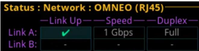
Figure 14.4: Status | Network | OMNEO (RJ45)
Link A Column
The Link A column displays the link status, connection speed, and duplex status for the Link A OMNEO (RJ45) connection.
Link B Column
The Link B column displays the link status, connection speed, and duplex status for the Link B OMNEO (RJ45) connection.
Link Up Field
The Link Up field displays the status of data communication on the OMNEO (RJ45) port. Available statuses are:
 | The link is up |
 | The link is not up, but an IP address is defined |
| [2C20] | No IP address is defined |
Speed Field
The Speed field displays the transmission speed over the OMNEO interface.
The OMNEO interfaces support 100 Mbps and 1 Gbps.
Duplex Field
The Duplex field displays the transmit mode the OMNEO network interface is currently operating.
Almost all Ethernet interfaces auto-negotiate to full duplex. If the interface displays half duplex mode, this typically signifies the auto-negotiate failed, resulting in network collisions and errors.
Available options for this field are:
| Half-Duplex Can either transmit or receive, but not both simultaneously |
| Full-Duplex Can transmit and receive simultaneously |
14.4 RVON
The RVON screen is used to view the status of the RVON network status.

Figure 14.5: Status : Network : RVON screen
Link Up Field
The Link Up field displays the status of data communication on the RVON port. Available statuses are:
 | The link is up |
| [703T] | The link is not up, but an IP address is defined |
 | No IP address is defined |
Speed Field
The Speed field displays the transmission speed over the RVON port. The Ethernet links support 100 Mbps or 1 Gbps.
Duplex Field
The Duplex field displays the transmit mode the RVON network connection is currently operating.
Almost all Ethernet interfaces auto-negotiate to full duplex. If the interface displays half duplex mode, this typically signifies the auto-negotiate failed, resulting in network collisions and errors.
Available options for this field are:
| Half-Duplex Can either transmit or receive, but not both simultaneously |
| Full-Duplex Can transmit and receive simultaneously |
15 Status | Ports menu
Use the Ports menu to view port status for the following port and device types:
OMNEO
RVON
AIO
2-Wire
Devices
TIF

Figure 15.1: Status | Ports | Menu Icons
15.1 OMNEO
The OMNEO screen displays the status for OMNEO ports.
| Status: Ports : OMNEO | |||
| Port: | OM02 (OM01) | ||
| Device Name: | FALCON-06 | ||
| Connected: | IDLE | Duration: | - |
| IP Address: | 0.0.0.0 | RX Latency: | 2 ms |
| Device Type: | OKP-2 | Channel: | 1 |
| Description: | |||
| Drops: | - | ||
Figure 15.2: Status | Ports | OMNEO
Port Field
The Port field shows the port alpha and the port number.
Device Name Field
The Device Name field displays the name of the device to which this port is configured to connect.

Notice!
The device name always populates the field, unless the device connected to the port is a third party Dante device.
Connected Field
The Connected field is used to view the state of the connection. Typical states are Idle and Connected; however there can be transitional states during connection setup and tear down. The connection states available are Connected and Idle.
Duration Field
The Duration field is used to view the duration of the connection.
This field is displayed in days and hh:mm:ss (for example, 3 days 02:32:23).
IP Address Field
The IP Address field displays the IP address of the OMNEO device to which this port is connected.
Rx Latency Field
The Rx Latency field displays the latency of receive audio for this connection.
Device Type Field
The Device Type field displays the type of device connected to the port.
Channel Field
The Channel field displays the channel number on the device to which this port is connected.
Description Field
The Description field displays the description of the channel.
Drops Field
The Drops field displays the number of times a connection has been disconnected.
15.2 RVON
The RVON screen displays the status for RVON ports.
| Status: Ports : RVON | |||
| Port: | RVN1 | ||
| Connected: | IDLE | Duration: | - |
| IP Address: | 192.168.0.40 | Codec: | G.711μ |
| Device Type: | RVON-KP | Packet Size: | 10 ms |
| Channel: | 2 | VAD: | -40 dBm |
| Description: | |||
| Drops: | - | ||
Figure 15.3: Status | Ports | RVON
Port Field
The Port field shows the port alpha and the port number.
Connected Field
The Connected field displays the state of the connection. Typical states are Idle and Connected; however, there can be transitional states during connection setup and tear down. The connection states available are Connected and Idle.
Duration Field
The Duration field displays the duration of the connection. This field is displayed in days and hh:mm:ss (for example, 3 days 02:32:23).
IP Address Field
The IP Address field displays the IP address of the RVON device to which this port is connected.
Codec Field
The Codec field displays the codec type configured for the RVON port.
Device Type Field
The Device Type field displays the type of device connected to the port.
Packet Size Field
The Packet Size field displays the size of each audio packet. The packet size determines the amount of audio carried across the network in each transmitted packet.
Channel Field
The Channel field displays the channel number on the device to which this port is connected.
VAD Field
The VAD (Voice Activity Detection) field displays the threshold at which point audio transmits across the network.
Description Field
The Description field displays the description of the channel.
Drops Field
The Drops field displays the number of times an interruption in the connection occurs.
15.3 AIO
The AIO screen is used to display the AIO port status, which includes keypanel status and communication error counters.
| Status : Ports : AIO | ||||
| AIO —— Port —— Status — Errors To/From — BER To/From- | ||||
| 01 | AIO1 | - | - / - | - / - |
| 02 | AIO2 | - | - / - | - / - |
| 03 | AIO3 | - | - / - | - / - |
| 04 | AIO4 | - | - / - | - / - |
Figure 15.4: Status | Ports | AIO Screen
AIO Column
The AIO column displays the number of the physical AIO connector located on the back of the device.
Port Field
The Port field shows the port alpha and the port number.
Status Field
The Status field displays the connection status.
Available statuses are:
 | The panel is connected |
| [7082] | The panel was connected, but is no longer connected. |
| [2337] | There is no connection. |
Errors To / From Field
The Errors To / From field displays the number of errors that have occurred in sending and receiving messages via the AIO port.
BER To / From Field
The BER (Burst Error Rate) To / From field displays the number of errors that have occurred in the last 10 minutes, when sending or receiving messages via the AIO port. If the intercom has been running less than 10 minutes, it prorates the number of errors that would occur in a 10 minute period at the same rate. For example, three errors in five minutes would be shown as a BER of 6.
The maximum displayed BER value is 255.
15.4 2-Wire
The 2-Wire screen displays status information for the four connectors, CH A, CH B, CH C, and CH D located on the rear panel of the device.
| Status : Ports : 2-Wire | |||||
| XLR ————Port———Mode——-Loop--Signal--Audio--PWR- | |||||
| CH A | CH A | Audiocom | ✘ | - | ✘ |
| CH B | CH B | Clear-Com | ✘ | - | ✘ |
| CH C | CH C / CH D | RTS 1 | ✓ | - | ✘ |
| CH D | CH C / CH D | RTS 2 | ✓ | - | ✘ |
Figure 15.5: Status | Ports | 2-Wire Screen
Port Field
The Port field shows the port alpha and the port number.
Mode Field
The Mode field displays the operating mode of the channel.
Available modes are:
| Off No modes are active | |
| RTS 1 RTS Channel 1 | Mode |
| RTS 2 RTS Channel 2 | Mode |
| Audiocom Audiocom | Mode (balanced) |
| Clear-Com ClearCom | Mode (unbalanced with DC call) |
Loop Field
Use the Loop field to configure a pair of ports to act as a loop in and loop out connectors. CH B can be configured as a loop out connector for CH A. Additionally; CH D can be configured as a loop out connector for CH C.
Configuring a pair of connectors for looping allows greater flexibility when installing the 2-Wire wiring.
Signal Field
The Signal field displays whether a signal has been detected on the 2-wire port.
Signals displayed are: Mic Kill, Setup, Call, and DC Call.
Audio Field
The Audio field displays a real-time VU meter (audio signal strength) for each port. The segmented bar graph is used to show audio is present on the port and the strength of the audio. Audio signals below -4 dBU are shown in green, while signals between +4 dBU and +2 dBU dB are shown in yellow and signals greater than +2 dBU are shown in red.
PWR Field
The PWR field indicates whether OMS detects DC Power (for example, voltage) on the 2W line. In most systems, there is a power supply like a PS-20 on the 2W line, which provides power to the beltpacks. This status indication could be useful to ensure that the system is set up correctly.
15.5 Devices
The Devices screen displays status information of connected devices.
![Status : Ports : Devices Port: OM01 Connected: ✓ Powerups: 2 Device Type KP-4016/4 Requests: 930 Version: KP-4016, Version 2.5.0 [RSTP], Apr 6 2020, CRC=1ab4](/content/2026/06/1368847/images/3823274d3b66fb261030db3aa095cf4c2ce46b08d3ba7e174a0bf806521b19c2.jpg)
Figure 15.6: Status | Ports | Keypanel
Port Field
The Port field is used to select the port to view.
Connected Field
The Connected field displays the status information of the connection.
Available statuses are:
| ✓ | The device is connected |
| ✘ | The device was connected, but is no longer connected. |
| - | There is no connection. |
Devices Type Field
The Devices Type field displays the type of device is connected to the intercom.
Version Field
The Version field displays the firmware version currently loaded on the device.
Powerups Field
The Powerups field displays the number of times the device reboots or loses and then regains its connection.
Requests Field
The Requests field displays the number of device requests received by the intercom (for example, assigning a key, turning a listen key on/off, assigning a program source to an IFB, etc).
15.6 TIF
The TIF screen is used to view the status information of any TIFs connected to the selected device.

Figure 15.7: Status | Ports | TIF
TIF Field
The TIF field displays the ports with TIFs connected.
Port Field
The Port field displays the port to which the TIF is connected.
Status Field
The Status field displays the status of the TIF.
Available states are:
Off-hook
Ringing
- (on-hook/idle)
16 Status | Peripherals menu
Use the Peripherals menu to access the status of GPIO-16 devices.

Figure 16.1: Status : Peripherals Menu
16.1 GPIO-16
| Status: Peripherals: GPIO-16 | |||
| GPIO-16 -Status--Errors To/From--BER To/From- | |||
| 01 | - | - / - | - / - |
| 02 | - | - / - | - / - |
| 03 | - | - / - | - / - |
| 04 | - | - / - | - / - |
Figure 16.2: Status | Peripherals | GPIO16 Screen
GPIO-16 Column
The GPIO-16 column displays the number of the GPIO-16.
Status Field
The Status field displays the GPIO-16 port communication status.
Available statuses are:
| ✓ | The GPIO-16 is connected |
| ✘ | The GPIO-16 was connected, but is no longer connected |
| - | There is no connection |
Errors To / From Field
The Errors To/From field displays the number of errors to and from the GPIO-16.
BER To / From Field
The BER To / From field displays the number errors to and from the GPIO-16 in the last 10 minutes.
17 Status | Intercom menu
Use the Intercom menu to access the status pages for GPIOs and crosspoint inspections.

Figure 17.1: Status : Intercom Menu
17.1 GPIO
The GPIO screen displays status information for General Purpose Inputs and Outputs in the intercom.

bar
Status : Intercom : GPIO | GPIO: | Outputs | |---|---| | 001 - 016 | ● | | 017 - 032 | ● | | 033 - 048 | ● | | 049 - 064 | ● | | 065 - 080 | ● | | 081 - 096 | ● |Figure 17.2: Status | Intercom | GPIO
GPIO Selection Field
The GPIO selection field is used to select whether Input status or Output status is displayed. Status LED descriptions are:
| Active Inputs (green light) | |
| Active Outputs (red light) | |
| Inactive Inputs or Outputs (grey light) |
17.2 Crosspoint inspect
The Crosspoint Inspect screen displays the crosspoint status for the selected input and output ports.

Figure 17.3: Status | Intercom | Crosspoint Inspect
Input Field
The Input field displays the input port alpha.

Notice!
To change the input port displayed, when the focus is on the input field, press the ENC2 encoder knob, and then turn the ENC2 encoder knob to scroll through port numbers.
Type Field
The Type field displays the port type.
In Gain Field
The In Gain field displays the input gain for the input port.
Output Field
The Output field displays the port on which output audio is sent.
Type Field
The Type field displays the port type.
Out Gain Field
The Out Gain field displays the output gain for the output port.
State Field
The State field displays the state of the crosspoint.
The available states are:
| The crosspoint is closed | |
| The crosspoint is inhibited (prevented from being closed, even if it would otherwise be closed). | |
| The crosspoint is open (no reason to close or inhibit). |
Gain Field
The Gain field displays the crosspoint gain.
Path Gain Field
The Path Gain field displays the overall gain that takes into account the input and output gains, as well as the crosspoint gain.
18 Status | Hardware menu
Use the Hardware menu to access status information for power supplies, device temperatures, and clock operation.

Figure 18.1: Status : Hardware Menu
18.1 Power supplies
The Power Supplies menu item displays power supply parameters for the different power supplies used by the device. OMS self-monitors the power used and if it finds any power levels outside the recommended operating conditions, an alarm generates.
- If the power is within the normal operating range, the entry shows in green (Normal).
- If the power is outside the normal operating range, but not in the alarm state, the entry shows in yellow (Marginal).
- If the power is outside the marginal operating range, the value shows in red (Alarm).

Notice!
This information is for diagnostic purposes only.
| Status: Hardware: Power Supplies | ||||||
| Supply | -Voltage | —Min | —Max | —Current | —Min | —Max |
| 5.0V | 5.00V | 5.00V | 5.00V | 1.94A | 1.90A | 2.23A |
| 3.3V | 3.30V | 3.30V | 3.30V | 0.54A | 0.44A | 0.59A |
| 24V | 24.09V | 24.09V | 24.13V | 0.59A | 0.57A | 0.65A |
Figure 18.2: Status | Hardware | Power Supplies Screen
Supply Field
The Supply field displays the different power supply voltages.
Voltages include: 5.0 V, 3.3 V, and 24 V.
Voltage Field
The Voltage field displays the latest voltage reading.
Min Field
The Min field displays the minimum voltage the power supply has recorded.
This value resets at reboot.
Max Field
The Max field displays the maximum voltage the power supply has recorded.
This value resets at reboot.
Current Field
The Current field displays the latest current reading.
Min Field
The Min field displays the minimum current recorded on the power supply.
This value resets at reboot.
Max Field
The Max field displays the maximum current recorded on the power supply.
This value resets at reboot.
18.2 Temperatures
The Temperatures menu item displays temperature readings for different components inside the device. The device has nine sensors that self-monitor across the board. If the temperatures are outside the recommended operating conditions, an alarm generates.
- If the temperature is within the normal operating range, the entry shows in green (Normal).
- If the temperature is outside the normal operating range, but not in the alarm state, the entry shows in yellow (Marginal).
- If the temperature is outside the marginal operating range, the value shows in red (Alarm).

Notice!
This information is for diagnostic purposes only.
| Sensor - Temperature- Min Max | |||
| CPU | +42°C | +41°C | +42°C |
| Audio FPGA | +44°C | +43°C | +44°C |
| OMNEO Ethernet | +40°C | +39°C | +40°C |
| 2-Wire | +40°C | +38°C | +40°C |
| Speaker Driver | +45°C | +43°C | +45°C |
| AC/DC supplies | +41°C | +40°C | +42°C |
| Power Management IC | +52°C | +50°C | +52°C |
| 5VDC Supply | +46°C | +45°C | +47°C |
| 3.3VDC Supply | +47°C | +45°C | +48°C |
Figure 18.3: Status | Hardware | Temperatures Screen
Sensor Field
The Sensor field displays the names of the different temperature sensors monitored on the device.
Temperature Field
The Temperature field displays the current temperature of the specific sensor. Temperatures only show in Celsius.
Min Field
The Min field displays the lowest recorded temperatures of the sensor from the time the device powers on.
Max Field
The Max field displays the highest recorded temperature of the sensor from the time the device powers on.
18.3 Clock
The Clock menu shows the status of the OMNEO audio synchronization clock. Operation of OMNEO audio requires that all devices on the network have a synchronized clock reference. The clock master sends a signal out to other networked devices for synchronization.

Figure 18.4: Status | Hardware | Clock
Clock Source Field
The Clock Source field displays the clock mode of the device. Devices can be either the clock master or the slave that receives the clock with which to synchronize. Available states for this field are:
| Network / Slave OMS receives its PTP clock from another device on the network. |
| Internal / Master OMS generates the PTP clock as the Master Clock for other devices on the network. |
PTP Clock Status Field
The PTP Clock Status field displays the synchronization status of the device to other devices on the network. PTP (Precision Time Protocol) synchronizes clocks throughout the network. Available status for this field are Linked or Unlinked.
Preferred Master Check Box
The Preferred Master check box determines whether the device is the preferred master clock.
19 Status | Key Status menu
Use the Key Status screen to show various key configuration options on each key on the device.

Figure 19.1: Status : Key Status Screen
Listen Radio Button
Use the Listen radio button to show the listen assignment on each key.
Level 2 Radio Button
Use the Level 2 radio button to show the Level 2 assignments on the keys.
Assign Type Radio Button
Use the Assign Type radio button to show the assignment type of the key.
Solo Radio Button
Use the Solo radio button to show keys with the solo key option.
Exclusive Radio Button
Use the Exclusive radio button to show keys with the exclusive key option.
Auto Dial Radio Button
Use the Auto Dial radio button to show keys configured with an auto dial.
To see the different assignments, do the following:
- Navigate to an assignment type radio button.
- Click the ENC 2 encoder knob.
The assignments appear in the panel display.
20 Configuration | System menu
Use the Configuration menu to configure system, network, port, audio, local keypanel, user preferences, and advanced settings.

Figure 20.1: Configuration Menu
System menu
Use the System menu to access the Intercom Name screen.

Figure 20.2: Configuration : System Menu
20.1 Intercom name
Use the Intercom Name menu to assign a name to the Intercom system. Intercom names can be 4-, 6-, or 8-character names, giving the user an option for name length.

Notice!
The 8 Unicode field cannot be changed at the device. To make changes to the 8 Unicode field, use the AZedit configuration software.
Figure 20.3: Configuration | System | Intercom Name
4 Character Field
Use the 4 Character field to enter a four character intercom name.
6 Character Field
Use the 6 Character field to enter a six character intercom name.
8 Character Field
Use the 8 Character field to enter an eight character intercom name.
8 Unicode Field
The Unicode field displays the 8-character Unicode intercom name. This field is not editable. If the Unicode name is the same as the 8-character name, any changes to the 8 Character field ripple down to this field.
21 Configuration | Network menu
Use the Network menu to access the settings for the Control port, OMNEO port, and RVON port.

Figure 21.1: Configuration : Network Menu
21.1 Control port
The Control Port is used to configure the network connection to AZedit.

Figure 21.2: Configuration | Network | Control Port
IP Address Field
The IP Address field is used to enter the IP address assigned to the Control Port interface.
Network Field
The Netmask field is used to enter the netmask address.
Gateway Field
The Gateway field is used to enter the gateway address, if applicable.
DNS Server Field
The DNS Server field is used to enter the DNS server IP address, if applicable.
21.2 OMNEO
Use the OMNEO screen to configure the OMNEO network interface.
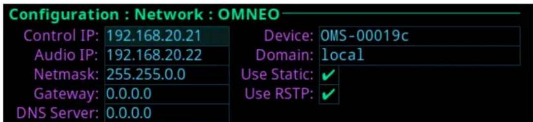
Figure 21.3: Configuration | Network | OMNEO
Control IP Field
Use the Control IP field to enter the IP address used by the OMNEO Control interface to access the network. The Controller sets up audio connections between two OMNEO configured ports. This address must be in the same subnet as the Audio IP.
By default, OMNEO interfaces use link local range address and are DHCP enabled. If there is a DHCP server on the network, it takes an IP address from the DHCP server.
The controller and the audio device are tightly coupled. Failure to communicate between the controller and the audio device may cause unexpected results.
Audio IP Field
Use the Audio IP field to enter the IP Address used to transmit and receive audio across the network.
By default, OMNEO interfaces use link local range addresses and are DHCP enabled. If there is a DHCP server on the network, it takes an IP Address from the DHCP Server. The controller and the audio device are tightly coupled and must be in the same subnet. Failure to communicate between the controller and the audio device may cause unexpected results.
Netmask Field
Use the Netmask field to enter the netmask address.
Gateway Field
Use the Gateway field to enter the gateway address, if applicable.
DNS Server Field
Use the DNS Server field to enter the DNS server address for the OMNEO interface.
Device Field
Use the Device field to enter the name of the OMS device used by other OMNEO devices.
Domain Field
Use the Domain field to enter the domain in which OMNEO resides. Leave this field blank if multiple domains are not used. This implies the .local domain is used.

Notice!
It is necessary to enter a DNS server address when providing a domain.
Use Static Check Box
Select the Use Static check box to determine whether the IP address for the OMNEO interface is fixed and manually entered.
Use RSTP Check Box
Select the Use RSTP check box to determine whether RSTP is used on the port. See RSTP, page 67.
21.3 RVON
Use the RVON screen to configure the RVON network interface.

Figure 21.4: Configuration | Network | RVON
IP Address Field
Use the IP Address field to enter the IP address of the RVON Port interface.

Notice!
The RVON Port can be on a different network from the OMNEO and Control Port interfaces.
Netmask Field
Use the Netmask field to enter the netmask address.
Gateway Field
Use the Gateway field to enter the gateway address, if applicable.
22 Configuration | Ports menu
Use the Ports menu to access configuration pages for OMNEO ports, RVON ports, and 2-wire ports.

Figure 22.1: Configuration: Ports Menu
22.1 Connect Devices
Use the Connect Devices screen to search for and select available OMNEO devices to add to the system. OMS automatically searches the system for any available OMNEO devices and then lists them in the display window. It is possible to connect all devices to the OMS or select individual OMNEO devices to connect.

Figure 22.2: Searching Connect Devices

Figure 22.3: Configuration | Ports | Connect Devices Screen
Connect All Button
Use the Connect All button to confirm the addition of the discovered devices to the system. Selecting a device displays the Available Channel screen.

Figure 22.4: Available channel screen

Figure 22.5: Connecting channel screen
Source Channel Field
Use the Source Channel field to view the name of the channel to which the device is connecting.
Channel Status Field
Use the Channel Status field to view the status of the channel to which the device is connecting.
For more information, please refer to Connect OMNEO devices to OMS using Connect Devices, page 29.
22.2 OMNEO channels

Figure 22.6: Configuration | Ports | OMNEO Channels
Port Field
Use the Port field to select which port to configure.
Device Name Field
Use the Device Name field to enter the name of an OMNEO device to which this port attempts to connect.
IP Address Field
The IP Address field displays the IP address of the device specified in the Device Name field.
Device Type Field
Use the Device Type field to select the type of device to which this port attempts to connect.
Rx Latency Selection Field
Use the Rx Latency selection field to set the latency threshold of the receive audio. This setting determines the delay between when a device transmits audio to when that audio is received on the connected device. It is sometimes necessary to use a higher latency setting in large networks to avoid brief audio disruptions.
Available options for this field are: 1 ms, 2 ms, 5 ms, 10 ms, 15 ms, and 20 ms.
The default value for this field is 2 ms.
Channel Field
Use the Channel field to select the channel on the partner device to which this port attempts to connect.
Description Field
The Description field displays the description of the port.
22.3 RVON channels
Figure 22.7: Configuration | Ports | RVON Channels Screen
Port Field
Use the Port field to select the port alpha for the RVON port.
IP Address Field
Use the IP Address field to enter the IP address of the RVON device to which this port should connect.
Codec Field
Use the Codec field to select the codec type for the RVON port.
Available options for this field is G.711a, G.711 , G.722, and G.729A.
Device Type Field
Use the Device Type field to select the type of RVON device connected to the port.
Packet Size Field
Use the Packet Size field to select the size of each audio packet. The packet size depends on the codec selected.
Available options for G.711a, G.711 , G.722 - 10 ms, 20 ms, and 30 ms; for G.729A - 10 ms, 20 ms, 40 ms, and 60 ms.
Channel Field
Use the Channel field to select the channel number on the device to which this port is connected.
VAD Field
Use the VAD field to select the threshold at which point audio transmits across the network.
The range for this field is -60 dBm to -30 dBm, or Off.
Description Field
Use the Description field to enter a description for the channel.
22.4 2-Wire ports
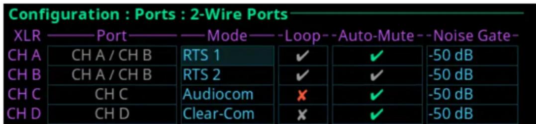
Figure 22.8: Configuration | Ports | 2-Wire
XLR Field
The XLR field displays the four 2-Wire channels (CH A, CH B, CH C, and CH D).
Port Field
The Port field displays the port and alpha assigned to the 2W channel.
Changes cannot be made to this field.
Mode Field
Use the Mode field to select the channel operation mode.
Available options are:
Off
Audiocom Balanced Audio, shared power and audio
Clear-Com Unbalanced, separate power and audio
RTS1 CH 1 Unbalanced, shared power and audio
RTS2 CH 2 Unbalanced, shared power and audio
Balanced and unbalanced refer to the type of audio signal being used.
| Unbalanced Audio | uses ground reference signaling |
| Balanced Audio uses differential signaling | |
By default, this field is set to Off.
Loop Field
Use the Loop field to configure a pair of ports to act as a loop in and loop out connectors. CH B can be configured as a loop out connector for CH A. Additionally; CH D can be configured as a loop out connector for CH C.
Configuring a pair of connectors for looping allows greater flexibility when installing the 2-Wire wiring.

Figure 22.9: Loop configuration for CH A and CH B

Notice!
When XLR-A and XLR-B are looped, this means both connectors are supporting the same pair of RTS-1 and RTS 2 channels and these ports to the intercom are port CH A and port CH B.
Auto-Mute Field
Use the Auto-Mute field to determine whether the 2W port automatically mutes. If the setting is enabled, the 2W port is muted whenever OMS detects the absence of DC power on the line (typically, because the cable on the 2W port was removed).
By default, the Auto-Mute is enabled.
23 Configuration | Audio menu

Figure 23.1: Configuration : Audio Menu
23.1 Headset Mic / Speaker
Use the Headset Mic / Speaker screen to configure how the headset microphone and speaker operates

Figure 23.2: Configuration | Audio Menu | Headset Mic/Speaker Screen
Microphone Section
The microphone section configures where the audio is coming from and the type of microphone used.
By default, if a headset is not detected, the headset mic input mutes to avoid noise getting to the system.
Auto-Mute Check Box
The Auto-Mute check box determines whether the mic input automatically mutes when a headset mic is not detected.
Mode Field
Use the Mode field to select the state of the headset mic.
Available options are:
Disabled
Enabled
Switched (default) When set to Switched, the Mic Sel key controls the state of the headset mic.
Type Field
Use the Type field to select the type of microphone or allow the device to detect automatically the type of microphone connected.
Available options are:
- Auto-Detect (default)
- Dynamic
- Electret
LEC Enable Check Box
Use the LEC Enable check box to determine whether LEC (Line Echo Cancellation) is enabled on the microphone.
LEC prevents echo and feedback from occurring between the microphone and the speaker.
AGC Attack Field
Use the AGC Attack field to set the speed at which the microphone gets to the activation threshold, the point where the circuit determines if sound is present. The smaller the attack time, the faster the mic turns on.
Available options are:
-0.5 ms
- 1.0 ms (default)
-2.0 ms
AGC Decay Field
Use the AGC Decay field to set the speed at which the gain transitions to silence during release.
Available options are:
- 500 ms
- 750 ms (default)
- 1000 ms
Noise Gate Field
Use the Noise Gate field to enable or disable an audio level at which the mic turns on. When enabled, the microphone audio only turns on when the audio level exceeds the configured threshold. When disabled, the microphone is always on.
Compression Field
Use the Compression field to change the audio's dynamic gain, meaning audio above the noise gate threshold changes according to the compression ratio selected. The compression changes the dynamic range of the mic input. In other words, loud sounds soften, while soft sounds amplify.
Available options are:
- 1:1
-2:1 - 3:1 (default)
-4:1
-5:1
-6:1
Headset Speaker Section
The Headset Speaker section controls the headset detection functions: auto-transfer, which detects if a headset is present, and mode, which determines when and where the user hears audio.
Mode-Left Field
The Mode Left field sets the state of the left headphone of the headset.
Available options are:
- Enabled
- Disabled
- Switched (default) - Switched operation means the Mic Select key controls the state of the headset speaker.
Mode Right Field
The Mode Right field sets the state of the right headphone of the headset.
Available options are:
- Enabled
- Disabled
- Switched (default) - Switched operation means the Mic Select key controls the state of the headset speaker.
Auto Transfer Check Box
The Auto Transfer check box determines automatically if a headset is present.
Dim Volume Field
Use the Dim Volume field to set the amount, in dB, to diminish the volume at the speaker. Activating any talk key causes the speaker volume at the keypanel to reduce by the amount specified.
Min Volume Field
Use the Min Volume field to set the minimum volume level, in dB, for the headset speaker. This is the minimum volume level available when using the Main Volume control knob.
Max Volume Field
Use the Max Volume field to set the maximum volume level, in dB, for the headset speaker. This is the maximum volume level available when using the Main Volume control knob.
Sidetone Mode Field
The Sidetone Mode field configures when sidetone activates on the headset speaker. Sidetone is the sound of your voice heard in the headset.
Available options are:
- Always On
- Disabled
- Switched (default) - the user's voice is heard only when a talk key is active.
Sidetone Level Field
Use the Sidetone Level field to set the level, in dB, at which the user hears their own voice. Most people prefer some amount of sidetone to overcome the muffled sensation when talking, especially when wearing a dual-sided headset.
23.2 Panel mic / speaker
Use the Panel Mic / Speaker screen to configure how the panel microphone and speaker operates.

Figure 23.3: Configuration | Audio | Panel Mic/ Speaker Screen
Microphone Section
The Microphone section configures the panel microphone.
Mode Field
Use the Mode field to select the state of the panel mic. Available options are:
Disabled
Enabled
Switched (default) When set to Switched, the Mic Sel key controls the state of the panel mic.
AEC Enable Check Box
The AEC Enable check box determines whether AEC (Acoustic Echo Cancellation) is active on the panel mic.
Use AEC to prevent echo and feedback from occurring between the microphone and the speaker. By default, the AEC is enabled.
AGC Attack Field
Use the AGC Attack field to set the speed at which the microphone gets to the activation threshold, the point where the circuit determines if sound is present. The smaller the attack time, the faster the mic turns on.
Available options are:
-0.5 ms
- 1.0 ms (default)
-2.0 ms
AGC Decay Field
Use the AGC Decay field to set the speed at which the gain transitions to silence during release.
Available options are:
- 500 ms
- 750 ms (default)
-1000 ms
Noise Gate Field
Use the Noise Gate field to enable or disable an audio level at which the mic turns on. When enabled, the microphone audio only turns on when the audio level exceeds the configured threshold. When disabled, the microphone is always on.
Compression Field
Use the Compression field to change the audio's dynamic gain, meaning audio above the noise gate threshold changes according to the compression ratio selected. The compression changes the dynamic range of the mic input. In other words, loud sounds soften, while soft sounds amplify.
Available options are:
-1:1
-2:1
- 3:1 (default)
-4:1
-5:1
-6:1
Speaker Section
The Speaker section configures the panel speaker.
Mode Field
Use the Mode field to select the state of the panel speaker.
Available options are:
Disabled
Enabled
Switched (default) When set to Switched, the Mic Sel key controls the state of the panel speaker.
Dim Volume Field
Use the Dim Volume field to set the dim volume for the panel speaker. When a talk key is enabled, the speaker volume will be reduced by the dim amount to reduce the echo and feedback.
Min Volume Field
Use the Min Volume field to set the minimum volume level, in dB, for the panel speaker. This is the minimum volume level available when using the main volume control knob, located on the front of the device.
Max Volume Field
Use the Max Volume field to set the maximum level, in dB, for the panel speaker. This feature prevents incoming audio being too loud.
The range for this field is Mute, -48 dB to +10 dB.
The default setting is +10 dB.
23.3 Filters
Use Filters to add input and output band pass filters and parametric equalization to local microphones and speakers.

Figure 23.4: Configuration | Audio | Filters Menu
23.3.1 Panel mic
Use the Panel Mic screen to configure a parametric equalizer on the panel mic.

Figure 23.5: Configuration | Audio | Filters | Panel Mic Screen
Enabled Check Box
The Enabled check box determines whether the parametric equalizer is enabled.
Presets Field
Use the Presets field to select one of five equalization settings. The equalization presets are predefined settings that modify the frequency envelope of an audio channel. This device has a 5-band equalizer. Each preset provides a different EQ to apply to the audio. When presets are used, band gains do not need to be set individually.
Available selections for this field are:
| Default 0 dB (15 Hz to 20 kHz) | |
| Hiss Reduction 0 dB (15 Hz to | 2 kHz)-6 dB (2 kHz to 12.6 kHz) |
| Rumble Reduction 0 dB (50 Hz to 20 kHz) | |
| Noise Reduction 0 dB (50 Hz to 2 kHz)-6 dB (2 kHz to 8 kHz)-80 dB (8 kHz to 12.6 kHz) | |
| None |
Adjustable 5-band Equalizer
An adjustable 5-band equalizer gives you the ability to adjust the low and high frequency cutoff filters and the gain for each band. This is in addition to the preset equalization settings on the local keypanel.
| 1 2 3 4 5 | |||||||||
| Low High | Low High | Low High | Low High | Low High | High | ||||
| 15.6 Hz | 125 Hz | 125 Hz | 500 Hz | 500 Hz | 2000 Hz | 2000 Hz | 8000 Hz | 8000 Hz | 12.6 kHz |
| 31.3 Hz | 15.8 | kHz | |||||||
| 50.0 Hz | 20.0 | kHz | |||||||
- Band 1 has three options for low cut-off frequency
- Bands 2, 3, and 4 have fixed frequencies
- Band 5 has three options for high cut-off frequency
Band Gains 1 through 5 Field
Use the Band Gains fields to adjust the gain for the selected frequency band.
Available selections for this field: -6.0 dB to 0.0 dB.
Low Frequency Field
Use the Low Frequency field to set the low point of the frequency band.
Available selections for this field: 50.0 Hz, 31.3 Hz, or 15.6 Hz.
High Frequency Field
Use the High Frequency field to set the high point of the frequency band.
Available selections for this field: 20.0 kHz, 15.9 kHz, or 12.6 kHz.
23.3.2 Headset mic
The Headset Mic option allows the user to configure where audio is coming from and the type of microphone used.
By default, if no headset is detected, the headset mic input is muted to avoid unwanted noise to the system.
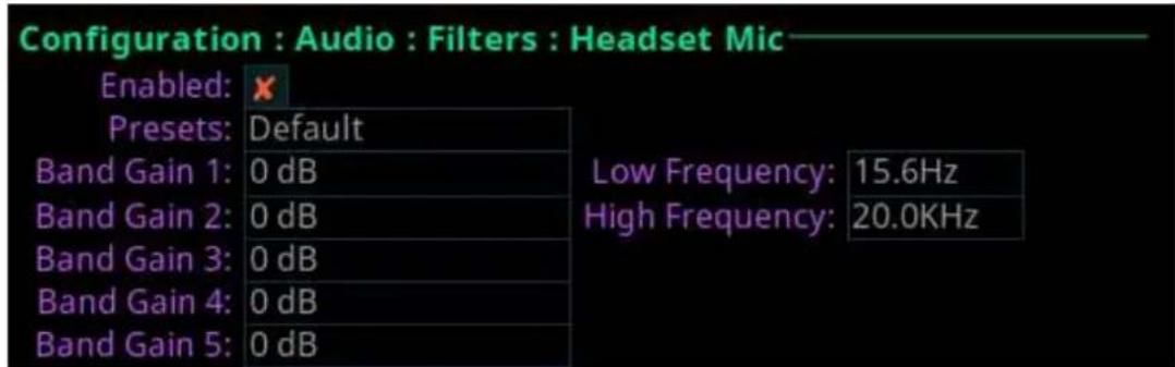
Figure 23.6: Configuration | Audio Filters | Headset Mic
Enabled Check Box
The Enabled check box determines whether users are able to modify presets, frequencies, and gain settings.
Presets Field
Use the Presets field to select one of five equalization settings. Equalizations are predefined settings that modify the frequency envelope of an audio channel. This device has a 5-band equalizer. Each preset provides a different EQ to apply to the audio. When presets are used, band gains do not need to be set individually.
Available selections for this field are:
| Default 0 dB (15 Hz to 20 kHz) | |
| Hiss Reduction 0 dB (15 Hz to 2 kHz) | -6 dB (2 kHz to 12.6 kHz) |
| Rumble Reduction 0 dB (50 Hz to 20 kHz) | |
| Noise Reduction 0 dB (50 Hz to 2 kHz) | -6 dB (2 kHz to 8 kHz)-80 dB (8 kHz to 12.6 kHz) |
| None |
Adjustable 5-band Equalizer
An adjustable 5-band equalizer gives you the ability to adjust the low and high frequency cutoff filters and the gain for each band. This is in addition to the preset equalization settings on the local keypanel.
| 1 2 3 4 5 | |||||||||
| Low High | Low High | Low High | Low High | Low High | High | ||||
| 15.6 Hz | 125 Hz | 125 Hz | 500 Hz | 500 Hz | 2000Hz | 2000Hz | 8000Hz | 8000Hz | 12.6kHz |
| 31.3 Hz | 15.8 | kHz | |||||||
| 50.0 Hz | 20.0 | kHz | |||||||
- Band 1 has three options for low cut-off frequency
- Bands 2, 3, and 4 have fixed frequencies
- Band 5 has three options for high cut-off frequency
Band Gains 1 through 5 Field
Use the Band Gains fields to adjust the frequency gain for the selected band. Available selections for this field: +6 dB to 0.0 dB.
Low Frequency Field
Use the Low Frequency field to set the low point of the frequency band. Available selections for this field: 50.0 Hz, 31.3 Hz, or 15.6 Hz.
High Frequency Field
Use the High Frequency field to set the high point of the frequency band. Available selections for this field: 20.0 kHz, 15.9 kHz, or 12.6 kHz.
23.3.3 Speaker
Use the Speaker screen to configure the frequency response of the speaker.

Figure 23.7: Configuration | Audio | Filters | Speaker
Enabled Check Box
The Enabled check box determines whether users are able to modify presets, frequencies, and gain settings.
Presets Field
Use the Presets field to select one of five equalization settings. Equalizations are predefined settings that modify the frequency envelope of an audio channel. This device has a 5-band equalizer. Each preset provides a different EQ to apply to the audio. When presets are used, band gains do not need to be set individually.
Available selections for this field are:
| Default 0 dB (15 Hz to 20 kHz) | |
| Hiss Reduction 0 dB (15 Hz to 2 kHz) | -6 dB (2 kHz to 12.6 kHz) |
| Rumble Reduction 0 dB (50 Hz to 20 kHz) | |
| Noise Reduction 0 dB (50 Hz to 2 kHz) | -6 dB (2 kHz to 8 kHz)-80 dB (8 kHz to 12.6 kHz) |
| None |
Adjustable 5-band Equalizer
An adjustable 5-band equalizer gives you the ability to adjust the low and high frequency cutoff filters and the gain for each band. This is in addition to the preset equalization settings on the local keypanel.
| 1 2 3 4 5 | |||||||||
| Low High | Low High | Low High | Low High | Low High | High | ||||
| 15.6 Hz | 125 Hz 125 | Hz 500 | Hz 500 Hz | 2000 | Hz | 2000Hz | 8000Hz | 8000Hz | 12.6kHz |
| 31.3 Hz | 15.8 | kHz | |||||||
| 50.0 Hz | 20.0 | kHz | |||||||
- Band 1 has three options for low cut-off frequency
- Bands 2, 3, and 4 have fixed frequencies
- Band 5 has three options for high cut-off frequency
Band Gains 1 through 5 Field
Use the Band Gains fields to adjust the frequency gain for the selected band.
Available selections for this field: +6 dB to 0.0 dB.
Low Frequency Field
Use the Low Frequency field to set the low point of the frequency band.
Available selections for this field: 50.0 Hz, 31.3 Hz, or 15.6 Hz.
High Frequency Field
Use the High Frequency field to set the high point of the frequency band.
Available selections for this field: 20.0 kHz, 15.9 kHz, or 12.6 kHz.
23.3.4 Headset Speaker

Figure 23.8: Configuration | Audio | Filters | Headset Speaker
Enabled Check Box
The Enabled check box determines whether the bandpass filter is applied to the headset speaker.
Low Frequency Field
Use the Low Frequency field to set the low point of the frequency band.
Available selections for this field: 50.0 Hz, 31.5 Hz, 15.6 Hz, or 0 Hz.
High Frequency Field
Use the High Frequency field to set the high point of the frequency band.
Available selections for this field: 22.0 kHz, 16 kHz, 8 kHz, or 4 kHz.
23.4 Mic options
The Mic Options screen is used to configure various mic settings.

Figure 23.9: Configuration | Audio | Mic Options Screen
Mic Mute Mode Field
Use the Mic Mute Mode field to select the actions of the Mic Mute key.
Available selections for this field are:
| Disabled By disabling the mic mute key, users are not able to mute the microphone from the front panel. | |
| Momentary The mic is muted for only as long as the mic mute key is held on. | |
| Toggle (default) | The mic mute key is enabled. In this mode, pressing the mic mute key toggles the mic mute state on and off. |
Hot Mic Check Box
The Hot Mic check box determines whether hot mic is active on the device. When enabled, audio from the mic goes out to the matrix without regard to the talk key state.
Panel Mic Gain Field
Use the Panel Mic Gain field to set the gain level the panel mic operates.
Headset Mic Gain Field
Use the Headset Mic Gain field to set the gain level the headset mic operates.
23.5 Tone generator
The Tone Generator checks the audio path from the device to the matrix. Use this screen to enable or disable the tone and set the frequency of the tone.

Figure 23.10: Configuration | Audio | Tone Generator Screen
Tone Enabled Check Box
The Tone Enabled check box determines if the tone generator is on or off.
Tone Frequency Field
Use the Tone Frequency field to set the tone frequency sent across the audio path.
Available options are:
- 500 Hz (default)
- 1 kHz
23.6 Key volumes
Use the Key Volumes menu to enable or disable the ability to adjust crosspoint listen gains. If enabled, users can adjust the listen gains for Matrix crosspoints using the key volume encoder knobs on the front panel. To adjust the minimum volume of each key, rotate the key volume encoder knob. As you rotate each knob, the associated key tile updates.

Figure 23.11: Configuration | Audio | Key Volumes Screen
Key Volume Adjust Check Box
The Key Volume Adjust check box determines whether users can adjust crosspoint listen gains.
23.7 Miscellaneous

Figure 23.12: Configuration | Audio | Miscellaneous Screen
Reference Level Field
Use the Reference Level field to set the audio level the device automatically adjusts. The device normalizes audio paths in the system using this level as a reference.
24 Configuration | Local Keypanel menu
Use the Local Keypanel menu to access key options, auto dial, panel swap, page change, call waiting window, and display option configuration pages.

Figure 24.1: Configuration | Local Keypanel Menu
24.1 Key options
Use the Key Options menu to configure key operation options for Solo keys, Exclusive keys, and Auto Dial.

Figure 24.2: Configuration | Local Keypanel Menu | Key Options Screen
Solo Keys
Solo gives the user the ability to set up a single key on the device that causes all other keys to turn off when activated. However, when the solo key releases, the keys turned off by the solo key turn back on.
The device allows only one solo key assignment
To assign a solo key to the device, do the following:
- Navigate to the Configuration icon.
- Click the ENC2 encoder knob.
- Navigate to the Local Keypanel icon.
- Click the ENC2 encoder knob.
- Navigate to the Key Options icon.
- Click the ENC2 encoder knob.
- Turn the ENC2 encoder knob to move the focus to Solo.
- Click the ENC2 encoder knob.
- Tap the desired talk key to assign the solo key option.
The key tile highlights with a red bar indicating which key is configured with the solo key option.
Exclusive Keys
Exclusive gives the user the ability to set up keys that cause other exclusive keys to turn off when activated. Unlike the solo option, when the exclusive key is released, the other exclusive keys turned off by the exclusive key do not turn back on.
The device allows multiple exclusive keys.
To assign an exclusive key on the device, do the following:
- Navigate to the Configuration icon.
- Click the ENC2 encoder knob.
- Navigate to the Local Keypanel icon.
- Click the ENC2 encoder knob.
-
Navigate to the Key Options icon.
-
Click the ENC2 encoder knob.
- Turn the ENC2 encoder knob to move the focus to Exclusive.
- Click the ENC2 encoder knob.
- Tap the desired talk key to assign the exclusive assignment.
The key tile highlights with a red bar indicating which key is configured with the exclusive key option.
Auto Dial
Auto Dial stores commonly used phone numbers in the auto dial list locally on the device. You can configure 1-Touch TIF Auto Dial numbers and configure those saved numbers to a device key. Once configured, pressing the assigned key causes the TIF to go off-hook and auto dial the configured number.
To assign an auto dial to a device key, do the following:
- Navigate to the Configuration icon.
- Click the ENC2 encoder knob.
- Navigate to the Local Keypanel icon.
- Click the ENC2 encoder knob.
- Navigate to the Key Options icon.
- Click the ENC2 encoder knob.
- Turn the ENC2 encoder knob to move the focus to Auto Dial.
- Click the ENC2 encoder knob.
- Tap the desired talk key to assign the auto dial assignment.
- Turn the ENC2 encoder knob or press the up arrow key to select the desired auto dial. The key tile highlights with a red bar indicating which key is configured with an auto dial number.
24.2 Auto dial
Auto dial stores commonly used phone number in the auto dial list locally on the device. To configure a key on the device to have an auto dial number, refer to Key options, page 117.

Figure 24.3: Configuration | Local Keypanel | Auto Dial Screen
Slot Field
Use the Slot field to select the entry number for the auto dial number. This number does not need to follow sequence.
Number Field
Use the Number field to enter a phone number to assign as an auto dial.
The device allows up to 100 auto dial entries.
To store an auto dial number, do the following:
- Navigate to the Configuration icon.
- Click the ENC2 encoder knob.
- Navigate to Local Keypanel.
- Click the ENC2 encoder knob.
- Navigate to Auto Dial.
- Click the ENC2 encoder knob.
-
Turn the ENC2 encoder knob or press the up arrow key on the keypad to select the desired slot.
-
Click the ENC2 encoder knob.
- Turn the ENC2 encoder knob to move the focus to the Number field.
- Click the ENC2 encoder knob.
- Enter the desired phone number.
- Click the ENC2 encoder knob.
- Click the ENC1 encoder knob.
- With the Save option highlighted, click the ENC2 encoder knob.
24.3 Panel Swap
Panel Swap gives users the ability to quickly access up to 16 virtual keys, allowing them to easily communicate with more people. Panel swap is different from changing setup pages because the keys can stay active even when they are no longer visible on the main display. When Panel Swap is enabled, users can switch to different key rows. With four key rows and each key row supporting four keys, there are 16 virtual keys. Turn the ENC1 encoder knob to change the active key row. Panel swap can also be activated by (or triggered by) a UPG key.

Figure 24.4: Configuration | Local Keypanel | Panel Swap Screen
# of Key Rows Field
Use the # of Key Rows field to select the number of key rows necessary.
Key States Field
Use the Key States field to define what happens to the key states when a row of keys is not currently visible. There are two possible modes of operation:
| Force Off Talk | talk and listen are forced off when the row of keys is not visible. |
| Retain Talk | and listen key states are retained when the row of keys is not visible, the following icon shows in the panel display when a virtual key is active on a key row not currently shown in the display. |
Keypad UPG Field
Use the Keypad UPG field to select what panel swap action occurs. There are four actions available:
| Cycle To Cycle to the next or previous key row. |
| Switch To Switch to a specific key row. |
| Toggle To Toggle between key row 1 and another key row. |
| Unassigned UPG does not control key row changes. |
24.4 Page Change
Use the Page Change screen to set the action of setup pages while talk keys are active.
Configuration : Local Keypanel : Page Change
Mode: Always Allow
Figure 24.5: Configuration | Local Keypanel | Page Change Screen
Mode Field
Use the Mode field to select the action of the setup pages when talk keys are active. By default, page changes are allowed when talk keys are active.
Available options:
| Always Allow Page changes are allowed while Talk Keys are active. |
| No Talk Keys Page changes are not allowed while Talk Keys are active. When page changes are restricted due to an active talk key, the page change interface is shown in grey. |
24.5 Call waiting window
Use the CWW menu to configure the CWW. There are two configuration options; how many calls show in the CWW and what happens when a new call comes in.
Configuration : Local Keypanel : Call Waiting Window
Number of Entries: 9 On New Caller: Don't Select
Figure 24.6: Configuration | Local Keypanel | Call Waiting Window Screen
Number of Entries Field
Use the Number of Entries field to define the number of calls shown in the CWW. The maximum number of entries is nine, while the minimum is three.
On New Caller Field
Use the On New Caller field to select what action occurs in the CWW when a new call enters the queue.
The options available are:
| Select New Call When | a new call enters the CWW queue, it goes to the top of the list and selects the new call. The highlight moves to this item. |
| Don't Select (default) | When a new call enters the CWW queue, it goes to the top of the queue, but the highlighted item does not change. |
| Select If Idle When a | new call comes into the CWW queue, it goes to the top of the queue list and the highlight moves to the new call only if the user has not interacted with the CWW in the last five seconds or if the CWW window is not visible. |
24.6 Footswitch
Use the Footswitch menu to enable the footswitch feature and configure how a latched talk key behaves when the user releases the footswitch. In normal footswitch operation, latched talk keys go into a ready state waiting for the footswitch press. When the footswitch is pressed, the latched talk keys become active. Then, when the footswitch releases, the latched talk keys go back into a ready state. The device can be configured so latched talk keys become
unlatched when the footswitch releases. In this mode, the footswitch is a one-time operation. Pressing the footswitch turns the keys on and releasing the footswitch turns the keys off, unlatching them so the keys are unable to come on again with the next press of the footswitch. To use the footswitch again, the desired keys must be re-latched.
A footswitch is a foot-triggered switch used to activate keypanel keys. OMS provides two methods for activating the footswitch feature:
- Opto-isolated input #1 on the GPIO terminal block, located on the rear panel.

flowchart
graph TD
    A["Cathode(H-)"] --> B["GND"]
    B --> C["Ground"]
    style A fill:#f9f,stroke:#333
    style B fill:#ccf,stroke:#333
Figure 24.7: Footswitch Cabling
- Pin 6 on the headset connector.
By default, the footswitch is disabled.
Configuration : Local Keypanel : Footswitch
Enable Footswitch: ✗ Unlatch Keys on Release: ✗
Figure 24.8: Configuration | Local Keypanel | Footswitch Screen
Enable Footswitch Check Box
The Enable Footswitch check box determines whether to enable the footswitch for the device.
Unlatch Keys on Release Check Box
The Unlatch Keys on Release check box determines whether latched talk keys become unlatched when the user releases the footswitch.
24.7 Display Options
Use the Display Options page to configure panel volume and listen assignment display options.
Configuration : Local Keypanel : Display Options
Show Panel Volume: ✗ Show Listen Assignment: Disable
Figure 24.9: Configuration | Local Keypanel | Display Options Screen
Show Panel Volume Check Box
The Show Panel Volume check box determines whether the speaker/headset volume window permanently displays, otherwise the window only appears when adjusting the volume.
Show Listen Assignment Field
Use the Show Listen Assignment field to enable or disable displaying listen assignments on the panel display.
25 Configuration | User Preferences menu
Use the User Preference menu to access user preference configuration options such as brightness, screen saver usage, alpha display, keypad state color, information display options, keypad hotkeys, and signaling options.

Figure 25.1: Configuration | User Preferences Menu
25.1 Brightness

Figure 25.2: Configuration | User Preferences | Brightness Screen
LCD Brightness
Use the LCD Brightness field to set the brightness of the panel.
Brightness ranges from 0% to 100%.
By default, the brightness is set at 100%.
Key Brightness
Use the Key Brightness field to set the brightness of the key backlights.
Brightness ranges from 0% to 100%.
By default, the brightness is set at 100%.
25.2 Screen saver
Use the Screen Saver screen to configure the way the screen saver operates.
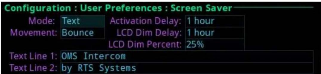
Figure 25.3: Configuration | User Preferences | Screen Saver
Mode Field
Use the Mode field to select the type of screen saver desired.
Available options are Bitmap, Text (default), or Blank.
Movement Field
Use the Movement field to select the type of movement the screen saver is to perform.
Available options are Bounce (default) or Scroll.
Activation Delay Field
Use the Activation Delay field to set the amount of time before the screen saver starts.
Available options for this field are Disabled, 12 hours, 10 hours, 8 hours, 6 hours, 4 hours, 2 hours, 1 hour (default), and 30 minutes.
LCD Dim Delay Field
Use the LCD Dim Delay field to set the amount of time before the LCD dims. When the screen saver or brightness dim mode becomes active, the key backlights also get dimmed.
Available option for this field are Disabled, 12 hours, 10 hours, 8 hours, 6 hours, 4 hours, 2 hours, 1 hour (default), and 30 minutes.
LCD Dim Percent Field
Use the LCD Dim Percent field to set the brightness of the panel display when the LCD dims, from 0 to 100%. This setting is a percentage of the current LCD brightness. For example, if the backlight is configured for 60%, then in this menu, 100% is equal to 60% and 0% is equal to 35%.
The default for this field is 25%
25.3 Alpha size
Use the Alpha Size screen to configure the alpha size (length) displayed when alphas are displayed on the front panel.

Figure 25.4: Configuration | User Interface | Alpha Size
Alpha Size Field
Use the Alpha Size field to select the size of alphas displayed on the front panel. Available sizes are 4 Characters, 6 Characters, 8 Characters, and 8 Unicode.
25.4 Keypad
Use the Keypad screen to configure how and when the keypad backlight activates and the color and brightness of the keypad backlight LEDs display in each keypad mode.

Figure 25.5: Configuration | User Interface | Keypad
Backlight Mode Field
Use the Backlight Mode field to select how and when the keypad backlight activates. Available options are:
| Activated (swallow first keypress) | The first keypad key pushed when the keypad is inactive is only used to activate the keypad. The actual keypad key push event is not acted upon. |
| Activated (process first keypress) (default) | The first keypad key pushed when the keypad is inactive activates the keypad and is processed. |
| Always Active The keypad backlight is always in the active state. | |
Always Inactive The keypad back!
ght is always in the inactive state. When selected, the LED color/brightness does not change when SHIFT is pressed, even if the keypanel is in SHIFT mode.

Notice!
When the front panel menu is not active, the backlight stays lit for 5 seconds of inactivity before returning to the inactive state. However, when the front panel menu is active, the backlight stays lit for one minute before exiting the menu system and returning to the inactive state.
Inactive State LED Color Field
Use the Inactive State LED Color field to select the LED backlight color when the keypad is in the inactive state.
Available options are Blue and White (default).
Active State LED Color Field
Use the Active State LED Color field to select the LED backlight color when the keypad is in the active state.
Available options are Blue and White (default).
Shift State LED Color Field
Use the Shift State LED Color field to select the LED backlight color when the keypad is in the Shift state.
Available options are Blue (default) and White.
LED Brightness Field
Use the LED Brightness field to set the brightness of the keypad backlight LEDs.
Brightness ranges from 0% to 100%.
By default, brightness is set for 30% for the Inactive state; and 100% for the Active and Shift states.
25.5 Options
Use the Options screen to configure advanced user interface options.
Configuration: User Interface: Options
Show Alarm Popups: Show Progress Popups: Auto-Hide Scrollbars:

Vertical Menu Transitions: Normal Horizontal Menu Transitions: Normal
Figure 25.6: Configuration | User Interface | Options
Show Alarm Popups Check Box
The Show Alarm Popups check box determines whether popup messages display when alarms trigger.
By default, Show Alarm Popups is enabled.
Show Progress Popups Check Box
The Show Progress Popups check box determines whether progress bars display on the front panel when writing new firmware, fonts, or resources to the intercom.
By default, Show Progress Popups is enabled.
Auto-Hide Scroll Bars Check Box
The Auto-Hide Scroll Bars check box determines whether a scroll bar shown on the right side of some screens auto-hides after a few seconds or if it is always visible.

Notice!
Not all screens have scroll bars. Only screens with more information than can fit on one display have the scroll bar capability.
By default, Auto-Hide Scroll Bars is enabled.
Vertical Menu Transitions Field
Use the Vertical Menu Transitions field to set the speed of or disable the vertical menu transitions. Vertical menu navigation, or sibling menu navigation, navigates the menu structure by moving between branches of the menu without having to go up one level and then back down again. For example, if the menu structure is at the top-level Configuration menu screen, turning the ENC1 encoder knob to the right one notch moves the menu structure to the top-level Intercom Setup menu.
If the focus of the menu is within a top-level menu structure, turning the ENC1 encoder knob to the right one notch moves the menu structure to the next menu item within the same top-level menu. For example, if the menu focus is at Configuration | Network, turning the left encoder knob to the right one notch moves the menu structure to Configuration | Ports.
Available options for this field are:
| Disabled No vertical transitions allowed. |
| None No transition animation is seen. Navigation is seen as jumps. |
| Normal The entire menu rolls up and down smoothly to reveal a new sibling. |
| Fast The entire menu rolls up and down faster than normal; however, it may not be as smooth. |
The default for this field is Normal.
Horizontal Menu Transitions Field
Use the Horizontal Menu Transitions field to set the speed of horizontal transitions within a menu. Horizontal menu transitions are movements within a menu structure to the next / previous menu item using the ENC2 encoder knob to navigate.
Available options for this field are:
| None No transition animation is seen. Navigation is seen as jumps. The purple focus frame jumps to a new menu item. |
| Normal The purple focus frame smoothly slides horizontally from icon to icon. |
| Fast The purple focus frame slides horizontally from icon to icon faster than normal; however, it may not be as smooth. |
The default for this field is Normal.
25.6 Keypad hotkeys
Use the Keypad Hotkeys screen to disable certain keypad functions such as the call keys, all-call, all-talk, mic kill, and stage announce functionality.
Figure 25.7: Configuration : User Preferences : Keypad Hotkeys Screen
Key 1 Call Enabled Check Box
The Key 1 Call Enabled check box determines whether the key 1 call button operates.
Key 2 Call Enabled Check Box
The Key 2 Call Enabled check box determines whether the key 2 call button operates.
Key 3 Call Enabled Check Box
The Key 3 Call Enabled check box determines whether the key 3 call button operates.
Key 4 Call Enabled Check Box
The Key 4 Call Enabled check box determines whether the key 4 call button operates.
All-Call Enabled Check Box
The All-Call Enabled check box determines whether the all-call button on the keypad is active.
All-Talk Enabled Check Box
The All-Talk Enabled check box determines whether the all-talk button on the keypad is active.
Mic Kill Enabled Check Box
The Mic Kill Enabled check box determines whether the mic kill button on the keypad is active.
Stage Announce Enabled Check Box
The Stage Announce Enabled check box determines whether the SA button on the keypad is active.
25.7 Signaling
Use the Signaling page to define call beep and mic kill usage.
Configuration : User Preferences : Signaling Enable Call Beeps: √
Figure 25.8: Configuration | User Preferences | Signaling
Enable Call Beeps Check Box
The Enable Call Beeps check box determines whether audible notifications can be heard when calls come into the device.
26 Configuration | Advanced menu
Use the Advanced menu to access configuration options for authentication, GPIO-16, clock, soft reboot, and diagnostics. There is a factory reset menu item that allows the device to be reset to factory defaults. To enable the factory reset menu item, refer to Factory reset, page 67.

Figure 26.1: Configuration | Advanced Menu
26.1 Authentication menu
Authentication is the process of determining someone's identity. Intercoms that support authentication may require a username and password for each AZedit/IPedit session. Use the Authentication menu to configure authentication parameters for AZedit, IPedit, and the keypad. Use the debug menu item to enable or disable the ability to run debug on the device.

Figure 26.2: Configuration | Advanced | Authentication Menu
26.1.1 AZedit
Use the AZedit Authentication screen to define whether authentication for AZedit is required. Up to 20 different user profiles can be created for different port authentication rules with user names, passwords, and admin rights.

Figure 26.3: Configuration | Authentication | AZedit
Enable Check Box
The Enable check box determines whether AZedit authentication is required. The Enable check box must be selected to enable authentication for AZedit.
The default for this field is enabled.

Notice!
If authentication is enabled and no users are defined, it is possible to become locked out of the intercom system. If this occurs, contact technical support for instructions on authentication bypass to gain access to the front panel where changes to the authentication settings can be made.
User Field
Use the User field to select which user profile to view and modify.
Up to 20 user profiles can be created.
Admin Check Box
The Admin check box determines whether the user profile has administrative rights.
The default for this field is the admin rights are enabled.
Name Field
Use the Name field to enter the name of a user or group. For example, the name could be an individual user such as John Adams; or the name could be a group, such as comms, where a group of users can use the same profile.
Password Field
Use the Password field is to enter a password for logging in. This field is optional.
26.1.2 IPedit
Use the IPedit Authentication screen to define the access privileges (read, write, or admin) for each user profile defined. When the Write and Admin check boxes both display red Xs, Read privilege is applied.
Up to five user profiles can be created in the authentication table.

Figure 26.4: Configuration | Authentication | IPedit
User Field
Use the User field to select which user profile to view and modify.
Write Check Box
The Write check box determines whether the user profile has Write privileges.
Admin Check Box
The Admin check box determines whether the user profile has administrative rights.
Name Field
Use the Name field to enter the name of a user or group. For example, the name could be an individual user such as John Adams; or the name could be a group, such as comms, where a group of users can use the same profile.
Password Field
Use the Password field to enter a password used to log into IPedit with the defined user profile.
The field is optional.
26.1.3 Front panel
Use the Front Panel screen to configure different access areas on the device, such as Front Panel access, Status menu access, Setup menu access, and Configuration menu access.

Notice!
PINs are hierarchical. Whenever a PIN is entered, access to the highest level of PIN entered is granted. If all three PINs are set, front panel access is PIN protected because a Status PIN is defined. However, if the Setup PIN is set, access to Status is granted, but access to the Configuration menu is not. If the user knows the Config PIN full access is granted.
Configuration: Authentication: Front Panel
Access: Unrestricted Timeout: 2 minutes
Status PIN:
Figure 26.5: Configuration | Authentication | Front Panel

Notice!
If the PIN is set, and then forgotten go to AZedit | Options | OMS Front Panel to reset the PIN.
Access Field
Use the Access field to set the level of security for the OMS front panel.
Available options are:
| Unrestricted (default) | The front panel has full access without any restrictions |
| Read Only The front panel is read only. No modifications can be made to any menu items. | |
| Authenticated The user must enter a PIN to access the front panel. | |
| Disabled The front panel has no access. | |
Timeout Field
Use the Timeout field to set the amount of time the front panel is idle before the user must re-enter a PIN when access is set to authenticated and a PIN is set.

Notice!
The front panel can be forced to logout (or forget a PIN has been entered) by manually activating the screen saver. To do this, press and hold the ENC1 encoder knob.
Available options are 1 minute to 15 minutes.
The default for this field is 2 minutes.
Status PIN Field
Use the Status PIN field to enter a numeric PIN used to access the Status menu. If a Status PIN is set, the user must enter the PIN to access any area on the front panel (for example, the Alarms menu is inaccessible without PIN).
This field can contain up to 20 digits.
Setup PIN Field
Use the Setup PIN field to enter a numeric PIN used to access the Intercom Setup menu. This field can contain up to 20 digits.
Config PIN Field
Use the Config PIN field to enter a numeric PIN used to access the Configuration menu.
This field can contain up to 20 digits.
26.1.4 Debug Shell
Configuration: Authentication: Debug Shell Access: Disabled
Figure 26.6: Configuration | Authentication | Debug Shell
Access Field
Use the Access field to grant access to the debug.
Telnet is available on the Control Port.
Available options are Enabled and Disabled (default).
26.2 GPIO-16 menu
Use the GPIO-16 menu to set the IP addresses of the GPIO-16 devices. OMS uses the Control Port to communicate to GPIO-16 devices.
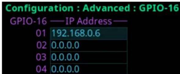
Figure 26.7: Configuration | Advanced | GPIO-16 Screen
To configure the GPIO-16 IP address, do the following:
-
Navigate to the desired position.
-
Click the ENC2 encoder knob.
The field becomes active.
-
Set the IP address.
-
Click the ENC2 encoder knob.
-
Click the ENC1 encoder knobto exit the screen.
A Changes Made message appears.
-
Navigate to the desired action.
-
Click the ENC2 encoder knob to confirm.
26.3 Clock Select
Use the Clock Select screen to configure the OMNEO audio PTP clock used to synchronize audio in an intercom system.
Configuration : Advanced : Clock Select Preferred Master: ✗
Figure 26.8: Configuration | Advanced | Clock Select
Preferred Master Check Box
The Preferred Master check box determines whether the device is configured as the preferred master clock for other OMNEO devices on the network.
By default the Preferred Master field is not selected.
26.4 Soft Reset
Use the Soft Reset screen to reboot the device without resetting any of the configurations. To perform a soft reset, do the following:
- Navigate to the Soft Reset icon.
- Click the ENC2 encoder knob.
The Soft Reset Confirmation message appears.

- Move the button focus to Do Reset.
- Click the ENC2 encoder knob.
A countdown message gives direction to press the MENU key on the keypad 5 times.

- Press the MENU key five times.
The device reboots.
26.5 Diagnostics
26.5.1 Test Panel
Use the Test Panel screen to check the operation of all physical controls on the front panel.

Figure 26.9: Configuration : Advanced : Diagnostics : Test Panel
Last Input on Front Panel field
The Last Input on Front Panel field displays the last physical control input after entering the test panel mode.
Keystroke Count Field
The Keystroke Count field displays the number of times the selected input is pressed, clicked, or tapped. For example, the D Talk button tapped three times displays the numeric three in the Keystroke Count field.

Notice!
The Keystroke Count field keeps a running tally of presses in memory until system restart.
To use the test panel function, do the following
- Navigate to the Configuration icon.
- Click the ENC2 encoder knob.
- Navigate to Advanced.
-
Click the ENC2 encoder knob.
-
Navigate to Diagnostics.
- Click the ENC2 encoder knob.
- Navigate to Test Panel.
- Click the ENC2 encoder knob.
The Test Panel screen opens.
-
Press any button on the front panel to test.
-
Press CLR to exit Test mode.
27 Intercom setup | Party line membership
Use Intercom setup to configure party line memberships, stored setups, devices, intercom resources, gains, and alphas.

Notice!
Changes made to the front panel settings save to flash immediately. However, it can take up to five minutes for changes made to the Intercom Setup to take effect.

Figure 27.1: Intercom | Setup Menu Icons
Party Line Membership
Use the Party Line Membership menu item to configure groups of devices that need to communicate simultaneously. Typically, party line audio is full duplex; meaning transmit and receive occur at the same time.
All ports can be members of a single party line.

Figure 27.2: Party line membership screen
Depending on the OMS model, the number of party lines and the type of ports may differ. The possible port types are:
- 40 OMNEO ports - 4 Two-Wire ports
- 4 RVON ports - 2 PGM ports
- 4 AIO ports - 1 SA port
- 1 OMS port - 8 TIE ports
Keys View
Use the Keys View to assign party line memberships to the different keys of the device. Different key states can occur when assigning keys in the Keys View.
| Key State Description | |
| White outline The | assignment will be added |
| Red outline The | assignment will be deleted. |
| Blinking The current | assignment (which is about to be deleted) and the proposed new assignment (which takes the place of the current assignment). ^1 When blinking:- The current assignment is shaded darker- The proposed new assignment is shown in the unshaded color. |
Key State Description
^1 If the current assignment is being removed from the key and not being replaced, the current assignment toggles with a Null assignment (blue key with dashes).
Tab. 27.18: Key assignment states for Party Line Membership Keys View screen

Figure 27.3: Party line configuration screen

Notice!
An asterisk next to the Keys View or Talker/Listener View radio button signifies there is already a membership configured.
To configure a party line membership using the keys view, do the following:
-
Navigate to the Party Line Membership menu item.
-
Press SEL.
The Party Line Membership matrix grid displays.
-
Use the arrow keys to navigate to the desired port and party line.
-
Press SEL.
The Keys View appears.
- Use the arrow keys to navigate to the desired key.
The Party Line Membership assignment key appears with a white outline.
- Press SEL.
The Party Line Membership assignment is configured and the Party Line Membership matrix grid appears.
To remove a party line membership assignment using the keys view, do the following:
-
Navigate to the Party Line Membership menu item.
-
Press SEL.
The Party Line Membership matrix grid displays.
-
Use the arrow keys to navigate to the desired port and party line.
-
Press SEL.
The Keys View appears with the assignment outlined in red and blinking.
- Press SEL.
The assignment is removed from the key and from the assignment grid.
Talker/Listener View
Use the Talker/Listener View to configure devices as permanent talkers, permanent listeners, both, or to clear the party line memberships. Two-wire ports, program inputs, stage announce, and TIE lines use the Permanent Talker/Listener screen exclusively for configuration of the party line memberships.
| Port 50: CHA PL 1: STAGE | Talker | Listener |
| Both | ▶ None |
Figure 27.4: Permanent talker/listener screen
There are four configuration options for this screen.
| Assignment Description | |
| Talker The party | line membership assignment is always talking. |
| Listener The party | line membership assignment is always listening. |
| Both The party | line membership assignment is always talking and listening. |
| None The party | line membership assignment is cleared from the key. |
Tab. 27.19: Configuration Options for Permanent Talker/Listener Screen
To configure a party line membership using the permanent talker/listener view, do the following:
- Navigate to the Party Line Membership menu item.
- Press SEL.
The Party Line Membership matrix grid displays.
- Use the arrow keys to navigate to the desired port and party line.
- Press SEL.
The Talker/Listener View appears.
- Use the arrow keys to select Talker, Listener, or Both.
- Press SEL.
The assignment is made and the Party Line Membership matrix grid appears with the configured party line membership.
To clear a party line membership from the talker/listener view, do the following:
- Navigate to the Party Line Membership menu item.
- Press SEL.
The Party Line Membership matrix grid displays with the assignment configured.
- Use the arrow keys to navigate to the desired port and party line.
- Press SEL.
The Talker/Listener View appears.
- Use the arrow keys to select None.
- Press SEL.
The assignment is removed and the Party Line Membership matrix grid screen appears with the membership removed.
28 Intercom setup | Stored Setups menu
Stored Setups are full AZedit setup files that are stored locally in the device and are recalled from the front panel (or AZedit) without having to send the file from AZedit. The device can configure, store, and save up to four setups (Slots).
The following is performed from the Stored Setups menu:
- Confirm slot validation
- Save the current setup to a slot
- Restore the setup from a valid slot
- Delete a valid setup
- Update the description of a valid setup.

Figure 28.1: Intercom Setup | Stored Setups Menu Icons
Slot 1 through Slot 4

Figure 28.2: Intercom Setup | Stored Setups | Slot 1
Valid Check Box
The Valid check box indicates whether there is a saved setup in the slot. If the slot is not valid, Restore, Delete and Update Description cannot be performed.
Description Field
Use the Description field to enter a detailed description of the Stored Setup (for example, "WeeknightNews").
This field can contain up to 130 characters.
Save Button
The Save button saves the current Intercom Setup to the selected slot (Slot 1, Slot 2, Slot 3, or Slot 4). Once the Save button is selected, a message appears in the display confirming the Save Action.
Restore Button
The Restore button loads and activates a setup file. For example, entering the Slot 3 Setup file menu option and selecting the Restore button replaces the current setup file with the Slot 3 stored setup file.
Delete Button
The Delete button erases the selected Stored Setup.
Update Description Button
The Update Description button confirms and updates the changes made to the description of the Stored Setup. Changes to the description can also be made in AZedit on the Stored Setups window (ONLINE | Stored Setups).

Notice!
The contents of a stored setup from OMS cannot be viewed. The Description field is used to describe in detail the saved setup parameters.
To save a setup, do the following:
- Click the Stored Setups icon.
The four setup slot folders display. - Click the slot to store the setup file.
- Enter a description for the stored setup.
- Click the Save button.
The Save current setup to slot

- Click the Proceed button.
The Stored Setup menu displays. The Saved Setup Slot folder shows with a green check mark.

28.1 Stored setups window
The Stored Setups window in AZedit is used to view and verify setup files as well as update descriptions.
To navigate to the Stored Setups screen in AZedit, select Stored Setups from the ONLINE menu.

Figure 28.3: Stored Setups screen from AZedit

Notice!
The Save, Restore, Delete, and Update Description buttons perform the same actions via AZedit as described for the front panel.
29 Intercom setup | Devices menu
The Devices menu is used to configure keypanel assignments, key options and setup pages in the intercom system.

Figure 29.1: Intercom Setup | Devices Menu
29.1 Key assignments
The Key Assignments screen configures key assignments on the device keys.

Figure 29.2: Intercom Setup | Devices | Key Assignments
Port Field
Use the Port field to select the desired port where the key assignment is to be assigned.
Page Field
Use the Page field to select the setup page where the key assignment is to be assigned.
Key Field
Use the Key field to select the key on the selected setup page where the key assignment is to be assigned.
Type Field
Use the Type field to select the key assignment type.
Selections for this field can include SPCL, PP, PL, IFB, SL, RY, ISO, and UR.
| SPCL Special |
| PP Point-to-Point |
| PL Party Line |
| IFB Interrupted Fold Back |
| SL Special List |
| RY Relay |
| ISO Camera Isolate |
| UR UPL Resource |
Alpha Field
Use the Alpha field to select the desired alpha to assign to the key. The alpha selection only shows the available instances of the selected type.
Latch Disable Check Box
The Latch Disable check box indicates the keypanel user cannot latch on the key. Clear the check box to enable latching capabilities. When Latching is enabled, the talk function stays on after the talk key is pressed briefly. Otherwise, the talk function only works when the button is pressed.

Notice!
A key only latches when pressed and released within 0.5 seconds. Otherwise, the key always turns off.
Key Restrict Check Box
The Key Restrict check box indicates the device key is restricted and modifications are disabled. Use this option to prevent a user from changing the key assignment.
To change key assignments, do the following:
- Navigate the Port field.
- Click the ENC2 encoder knob.
- Turn the ENC2 encoder knob to select the port.
- Click the ENC2 encoder knob to confirm the selection.
- Navigate to the Type field.
- Click the ENC2 encoder knob.
The field becomes active.
-
Rotate the ENC2 encoder knob to select the new assignment.
-
Click the ENC2 encoder knob to confirm the selection.
-
Click the ENC1 encoder knob to exit the screen.
A Changes Made confirmation message displays,
-
Navigate to the desired action.
-
Click the ENC2 encoder knob to confirm the selection.
29.2 Setup pages
Setup pages gives access to more key assignments than physical keys on the device. This is useful for sharing a device because setup pages can be used to swap between the key assignments used for each person.
Up to 4 setup pages per keypanel, port can be configured.
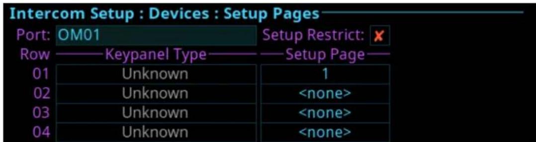
Figure 29.3: Intercom Setup | Devices | Setup Pages
Port Field
Use the Port field to select the desired port for the setup page assignment.
Setup Restrict Check Box
The Setup Restrict check box indicates the user is restricted from changing the setup pages.

Notice!
By default, modifications to setup pages are not allowed.
Row Field
The Row field displays the number of physical keys supported divided by 16. For example, a 64 key intercom shows four rows. A setup page can be configured for each row.
Keypanel Type Field
The Keypanel Type field identifies the type of device or expansion panel.
Setup Page Field
Use the Setup Page field to select the setup page for the selected keypanel or expansion panel.
To set up a setup page, do the following:
- Navigate to the Port field.
- Click the ENC2 encoder knob.
The field becomes active. - Turn the ENC2 encoder knob to scroll through the ports.
- Click the ENC2 encoder knob to select the desired port.
- Navigate to the Keypanel Type field.
- Click the ENC2 encoder knob.
The field becomes active.
- Select the keypanel type desired.
- Click the ENC2 encoder knob to confirm.
- Navigate to the Setup Page field.
-
Click the ENC2 encoder knob.
The field becomes active. -
Select the desired setup page.
- Click the ENC2 encoder knob to confirm.
- Click the ENC1 encoder knob to exit the screen.
A Changes Made confirmation message displays. - Navigate to the desired action.
- Click the ENC2 encoder knob to confirm the selection.
29.3 Scroll enables
Use the Scroll Enables screen to configure selected ports for scroll enable and/or latch disable.
Intercom Setup : Devices : Scroll Enables
Port: OM01
Scroll Enable:
Latch Disable:

Figure 29.4: Intercom Setup | Devices | Scroll Enables
Port Field
Use the Port field to select the port where scroll enable and latch disable is to be enabled or disabled.
Scroll Enable Check Box
The Scroll Enable check box determines whether the selected port is visible in scroll lists.
Latch Disable Check Box
The Latch Disable check box determines whether the selected device, when assigned to a key, causes the key to become latch disabled. Override this by clearing the latch disable for the key after the assignment is made.
To configure scroll enables, do the following:
-
Navigate to the Port field.
-
Click the ENC2 encoder knob.
The field becomes active.
-
Select the desired port.
-
Click the ENC2 encoder knob.
-
Navigate to the Scroll Enable check box.
-
Click the ENC2 encoder knob to enable or disable scroll enables.
-
Navigate to the Latch Disable check box.
-
Click the ENC2 encoder knob to enable or disable latch disable.
-
Click the ENC1 encoder knob to exit the menu.
A Changes Made confirmation message appears.
-
Navigate to the desired action.
-
Click the ENC2 encoder to confirm the selection.
30 Intercom setup | Resources menu
Use the Resources menu to setup intercom resources in the intercom.

flowchart
graph TD
    A["Intercom Setup : Resources"] --> B["Arrow to Node"]
    B --> C["Arrow to Node"]
    C --> D["Arrow to Node"]
    D --> E["Arrow to Node"]
    E --> F["Arrow to Node"]
    F --> G["Arrow to Node"]
Figure 30.1: Intercom Setup | Resources
30.1 Party line
Use the Party Line screen to configure party line membership and options. A party line system is a system in which a number of participants are involved in the same conversation. Party line systems are full-duplex conversations, meaning each person involved in a call talk simultaneously with others. It is a public conversation.

Figure 30.2: Intercom Setup | Resources | Party Line
PL Field
Use the PL field to select the party line to configure.
Port Field
Use the Port field to select the port to view or modify the party line membership.
Talker Check Box
The Talker check box designates the selected port as a permanent talker on the current party line. This means the port is always talking. The permanent talkers are usually only used with devices that cannot turn talk keys on and off. Keypanels normally do not have this option configured.
Listener Check Box
The Listener check box designates the select port as a permanent listener on the current party line assignment. This means the port is always listening. The permanent listeners are usually only used with devices that cannot turn listen keys on and off. Keypanels normally do not have this option configured.
Scroll Enable Check Box
The Scroll Enable check box determines whether the current PL is visible in the local scroll list.
Latch Disable Check Box
The Latch Disable check box determines whether the party line, when assigned to a key, causes the key to become latch disabled. Clear the latch disable for the key after making the assignment to disable this option.
Tally Enable Check Box
The Tally Enable check box determines whether the party line, if enabled, keypanel keys that have this key assignment tally when a user talks to the party line.
To configure a party line, do the following:
-
Navigate to the PL field.
-
Click the ENC2 encoder knob.
The field becomes active.
-
Select the desired party line.
-
Click the ENC2 encoder knob to confirm.
-
Navigate to the Scroll Enable check box.
-
Click the ENC2 encoder knob to enable or disable scroll enable.
-
Navigate to the Port field.
-
Click the ENC2 encoder knob.
The field becomes active.
-
Select the desired port.
-
Click the ENC2 encoder knob to confirm.
-
Navigate to the Latch Disable check box.
-
(Optional) Click the ENC2 encoder knob to enable or disable latch disable.
-
Navigate to the Talker check box.
-
(Optional) Click the ENC2 encoder knob to enable the party line as talker.
-
Navigate to the Listener check box.
-
(Optional) Click the ENC2 encoder knob to enable the party line as listener.
-
Navigate to the Tally Enable check box.
-
(Optional) Click the ENC2 encoder knob to enable tallies for the party line.
-
Click the ENC1 encoder knob to exit the screen.
A Changes Made message appears.
-
Navigate to the desired action.
-
Click the ENC2 encoder knob to confirm the selection.
30.2 IFB
Use the IFB screen to configure IFB definitions and options. IFB (Interrupted Fold Back) is a system in which there is one-way communication from a director to on-air talent or a remote location. An example of an IFB system is a remote reporter needs to hear the news feed to know their cue to report and a director needs to interrupt the news feed to tell the reporter information, such as how much time is left before commercial break.
| Intercom Setup: Resources: IFB | ||
| IFB: | IF01 | Scroll Enable: ✗ |
| Input: | Latch Disable: ✓ | |
| Output: | ||
| Listen: | Dim: Mute | |
Figure 30.3: Intercom Setup | Resources | IFB
IFB Field
Use the IFB field to select the desired IFB to configure.
Input Field
Use the Input field to select the IFB program input port. The program input always routes to the IFB output (except when interrupting the IFB).
Output Field
Use the Output field to select the IFB output port. The IFB Output is the audio heard by the talent. Audio from the input port (typically, program input audio) is routed to this output port, except when the IFB is interrupted.
Listen Field
Use the Listen field to select the listen source port. The listen source is what a keypanel operator would hear when they listen to an IFB (if the listen assignment is an AT, Auto-Table). Use the talent's pre-fade mic as the listen source so the keypanel operator can always hear the talent.
Scroll Enable Check Box
The Scroll Enable check box determines whether the current IFB is visible in the local scroll list.
Latch Disable Check Box
The Latch Disable check box determines whether the IFB, when assigned to a key, causes the key to become latch disabled. Clear the check box to override the latch disable for the key.
Dim Field
Use the Dim field to select how much the program input dims when an interruption occurs on the IFB port.
The range for this field is -1.0 dB to -80dB, and Mute.
The default for this field is Mute.
To configure an IFB, do the following:
- Navigate to the IFB field.
- Click the ENC2 encoder knob.
The field becomes active. - Select the desired IFB.
- Click the ENC2 encoder knob to confirm.
- Navigate to the Scroll Enable check box.
- Click the ENC2 encoder knob to enable or disable scroll enable.
- Navigate to the Input field.
- Click the ENC2 encoder knob.
The field becomes active. - Select the desired input port.
- Click the ENC2 encoder knob to confirm.
- Navigate to the Latch Disable check box.
- (Optional) Click the ENC2 encoder knob to enable or disable latch disable.
- Navigate to the Output field.
- Click the ENC2 encoder knob.
The field becomes active. - Select the desired output port.
- Click the ENC2 encoder knob to confirm.
- Navigate to the Listen field.
- Click the ENC2 encoder knob.
The field becomes active. - Select the desired listen port.
- Click the ENC2 encoder knob to confirm.
- Navigate to the DIM field.
- Click the ENC2 encoder knob.
The field becomes active. - Select the DIM amount.
- Click the ENC2 encoder knob to confirm the selection.
- Click the ENC1 encoder knob to exit the screen.
A Changes Made message appears. - Navigate to the desired action.
27. Click the ENC2 encoder knob to confirm the selection.
30.3 Special list
Use the Special List screen to configure Special List membership and options. A special list is a way for a keypanel operator to talk or listen to several destinations using a single key. This assignment type is useful for group calls or for paging.
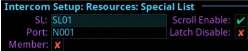
Figure 30.4: Intercom Setup | Resources | Special List
SL Field
Use the SL field to select the special list assignment to configure.
Port Field
Use the Port field to select the port whose SL membership to view or modify.
Member Check Box
The Member check box determines whether the selected port is a member of the special list. If selected, the port belongs to the special list.
Scroll Enable Check Box
The Scroll Enable check box determines whether the current SL is visible in the local scroll list.
Latch Disable Check Box
The Latch Disable check box determines whether the SL, when assigned to a key, causes the key to be latch disabled. Clear the latch disable for the key after the assignment is made to disable this option.
To configure an SL, do the following:
-
Navigate to the SL field.
-
Click the ENC2 encoder knob.
The field becomes active.
-
Select the desired SL.
-
Click the ENC2 encoder knob to confirm.
-
Navigate to the Scroll Enable check box.
-
Click the ENC2 encoder knob to enable or disable scroll enable.
-
Navigate to the Port field.
-
Click the ENC2 encoder knob.
The field becomes active.
-
Select the desired port.
-
Click the ENC2 encoder knob to confirm.
-
Navigate to the Latch Disable check box.
-
(Optional) Click the ENC2 encoder knob to enable or disable latch disable.
-
Navigate to the Member check box.
-
Click the ENC2 encoder knob to enable or disable SL Membership.
-
Click the ENC2 encoder knob to confirm the selection.
-
Click the ENC1 encoder knob to exit the screen.
A Changes Made message appears.
-
Navigate to the desired action.
-
Click the ENC2 encoder knob to confirm the selection.
30.4 Relay
Use the Relay screen to configure Relay definitions and options.
Relay definitions must be made for each input port and an output port. The associated relay activates when the input port and output port crosspoint closes. If there is only an input port definition or an output port definition, but not both, the definition is incomplete and the relay does not activate. In addition, UPL statements can activate relays.

Figure 30.5: Intercom Setup | Resources | Relay
Relay Field
Use the Relay field to select the relay to configure.
Scroll Enable Check Box
The Scroll Enable check box determines whether the current relay is visible in the local scroll list.
Latch Disable Check Box
The Latch Disable check box determines whether the Relay, when assigned to a key, causes the key to become latch disabled. After making the assignment, clear the latch disable to override the latch disable for the key.
To configure a relay, do the following:
- Navigate to the Relayfield.
- Click the ENC2 encoder knob.
The field becomes active. - Select the desired relay.
- Click the ENC2 encoder knob to confirm.
- Navigate to the Scroll Enable check box.
- Click the ENC2 encoder knob to enable or disable scroll enable.
- Click the ENC2 encoder knob to confirm.
- Navigate to the Latch Disable check box.
- (Optional) Click the ENC2 encoder knob to enable or disable latch disable.
- Click the ENC2 encoder knob to confirm the selection.
- Click the ENC1 encoder knob to exit the screen.
A Changes Made message appears. - Navigate to the desired action.
- Click the ENC2 encoder knob to confirm the selection.
30.5 ISO
Use the ISO (Isolate) screen to configure settings for ISOs in the intercom system. ISO is a means for a keypanel operator to isolate a particular intercom port for private communication. While the intercom port is isolated, it only hears audio from the keypanel operator. In television broadcasting, it is typical to ISO a member of the camera party line. The isolated camera can then receive directions without disruption from other audio traffic on the party line.

Figure 30.6: Intercom Setup | Resources | ISO
ISO Field
Use the ISO field to select the ISO to configure.
Output Field
Use the Output field to enter the port number of the port to isolate when the ISO key is pressed.
ISO Self Check Box
The ISO Self check box determines whether the ISO caller is isolated (as well as the target) so both ends only hear each other. Normal intercom operation automatically restores after releasing the ISO key.
Scroll Enable Check Box
The Scroll Enable check box determines whether the current ISO is visible in the local scroll list.
Latch Disable Check Box
The Latch Disable check box determines whether the ISO, when assigned to keys, causes the key to become latch disabled. After making the assignment, clear the latch disable to override the latch disable for the key.
To configure an ISO, do the following:
-
Navigate to the ISO field.
-
Click the ENC2 encoder knob.
The field becomes active.
-
Select the desired ISO.
-
Click the ENC2 encoder knob to confirm.
-
Navigate to the Scroll Enable check box.
-
Click the ENC2 encoder knob to enable or disable scroll enable.
-
Navigate to the Output field.
-
Click the ENC2 encoder knob.
The field becomes active.
-
Select the desired output port.
-
Click the ENC2 encoder knob to confirm.
-
Navigate to the Latch Disable check box.
-
(Optional) Click the ENC2 encoder knob to enable or disable latch disable.
-
Click the ENC2 encoder knob to confirm.
-
Navigate to the ISO Self? check box.
-
Click the ENC2 encoder knob to enable or disable ISO Self.
-
Click the ENC2 encoder knob to confirm the selection.
-
Click the ENC1 encoder knob to exit the screen.
A Changes Made message appears.
-
Navigate to the desired action.
-
Click the ENC2 encoder knob to confirm the selection.
31 Intercom setup | Gains menu
Use the Gains menu to set I/O gains, crosspoint gains, and party line gains.

Figure 31.1: Intercom Setup | Gains Menu Icons
31.1 I/O
Use the I/O screen to configure input and output gain for selected ports in the intercom system. When an intercom port interfaces with an external device operating at a different audio level than the intercom system, input and output gain adjustments are made to align the audio levels.

Figure 31.2: Intercom Setup | Gains | I/O
Port Field
Use the Port field to select the desired port's gain to view or modify.
Input Gain Field
Use the Input Gain field to set the amount of gain, in dB, applied to the selected port's input audio.
The range for this field is +20 dB to -20 dB.
Output Gain Field
Use the Output Gain field to set the amount of gain, in dB, applied to the selected port's output audio.
The range for this field is +20 dB to -20 dB.
To adjust the I/O gain, do the following:
- Navigate to the Port field.
- Click the ENC2 encoder knob.
The field becomes active. - Select the desired port.
- Click the ENC2 encoder knob to confirm.
- Navigate to the Input Gain field.
- Click the ENC2 encoder knob.
The field becomes active. - Select the desired input gain amount.
- Click the ENC2 encoder knob to confirm.
- Navigate to the Output Gain field.
- Click the ENC2 encoder knob.
The field becomes active. - Select the desired output gain amount.
-
Click the ENC2 encoder knob to confirm.
-
Click the ENC1 encoder knob to exit the screen.
A Changes Made message appears. - Navigate to the desired action.
- Click the ENC2 encoder knob to confirm the selection.
31.2 Crosspoint
Use the Crosspoint Gains screen to configure individual gain levels for crosspoints within the intercom system. Crosspoint gain adjustments adjust the level between two specific intercom ports.
Intercom Setup : Gains : Crosspoint
Port: OM01
Listening To: OM01
Crosspoint Gain: 0 dB
Figure 31.3: Intercom Setup | Gains | Crosspoint
Port Field
Use the Port field to select the desired output port's crosspoint listen gains to view or modify.
Listening To Field
Use the Listening To field to select the input port to which the selected output port is listening.
Crosspoint Gain Field
Use the Crosspoint Gain field to select the gain at which the selected port hears the selected input port.
The range for this field is -80 dB to +6.0 dB, and Mute.
To adjust the crosspoint gain, do the following:
- Navigate to the Port field.
- Click the ENC2 encoder knob.
The field becomes active. - Select the desired port.
- Click the ENC2 encoder knob to confirm.
- Navigate to the Listening To field.
- Click the ENC2 encoder knob.
The field becomes active. - Select the desired listening to port.
- Click the ENC2 encoder knob to confirm.
- Navigate to the Crosspoint Gain field.
- Click the ENC2 encoder knob.
The field becomes active. - Select the desired crosspoint gain amount.
- Click the ENC2 encoder knob to confirm.
- Click the ENC1 encoder knob to exit the screen.
A Changes Made message appears. - Navigate to the desired action.
- Click the ENC2 encoder knob to confirm the selection.
31.3 Party line
Use the Party Line screen to set the gain level for ports listening to party lines.
Intercom Setup : Gains : Party Line
Port: OM01
Listening To: PL01
PL Gain: 0 dB
Figure 31.4: Intercom Setup | Gains | Party Line
Port Field
Use the Port field to select the desired port's party line listen gains to view or modify.
Listening To Field
Use the Listening To field to select the party line to which the selected port is listening.
PL Gain Field
Use the PL Gain field to select the gain at which the selected port hears the selected party line.
The range for this field is -80 dB to +6.0 dB, and Mute.
To adjust the party line gain, do the following:
-
Navigate to the Port field.
-
Click the ENC2 encoder knob.
The field becomes active.
-
Select the desired port.
-
Click the ENC2 encoder knob to confirm.
-
Navigate to the Listening To field.
-
Click the ENC2 encoder knob.
The field becomes active.
-
Select the desired listening to gain amount.
-
Click the ENC2 encoder knob to confirm.
-
Navigate to the PL Gain field.
-
Click the ENC2 encoder knob.
The field becomes active.
-
Select the desired output gain amount.
-
Click the ENC2 encoder knob to confirm.
-
Click the ENC1 encoder knob to exit the screen.
A Changes Made message appears.
-
Navigate to the desired action.
-
Click the ENC2 encoder knob to confirm the selection.
32 Intercom Setup | Alphas menu
Intercom Setup : Alphas


Figure 32.1: Intercom Setup | Alphas Menu
Use the Alphas menu to view and modify the alphas for key assignment resource types.
Configurable assignment types are Ports, Party Lines, IFBs, Special Lists, Relays, and ISOs.
Alpha modifications change the current alpha size, plus all larger sizes where that alpha is the same as the currently modified alpha. For example, the 4-character alpha TEST, the 6-character alpha is TEST, and the 8-character alpha is SEAN. Changes made to the 4-character alpha are made to the 6-character alpha, but not to the 8-character alpha.
Available options are:
4 Character
6 Character
8 Character
8 Unicode
32.1 Alphas
Figure 32.2: Intercom Setup | Alphas | Port
Port Field
The Port field is used to select the port for which to configure Alpha text.
4 Character Field
The 4 Character field is used to enter a four character alpha.
6 Character Field
The 6-Character field is used to enter a six character alpha.
8 Character Field
The 8 Character field is used to enter an eight character alpha.
8 Unicode Field
The 8 Unicode field displays the eight character Unicode port alpha.
Changes cannot be made to this field.
To configure the alpha size, do the following:
-
Navigate to the desired assignment type.
-
Click the ENC2 encoder knob.
The Alpha Configuration form displays.
-
Navigate to the Port field.
-
Click the ENC2 encoder knob.
The Port field becomes active.
-
Scroll to the port desired.
-
Click the ENC2 encoder knob.
- Navigate to the 4 Character, 6 Character, 8 Character, or 8 Unicode field.
- Click the ENC2 encoder knob.
- Enter the desired Alpha in the active port field.
- Click the ENC1 encoder knob.
A confirmation message appears.

- Verify the Save button has the focus.
- Click the ENC2 encoder knob.
The modifications are saved and the screen closes.
33 Alarms menu
The Alarms menu is used to access alarm notifications of events that occur in the intercom system.

Figure 33.1: Alarms Menu
When an alarm occurs, an Alarm Notification message appears on the front display. To clear this message, press the CLR button on the keypad. The CLR button hides the popup, but the alarm remains unacknowledged. Pressing the SHIFT button, and then the CLR button on the popup, automatically acknowledges all of the new alarms (33 as shown below). The number of new alarms display in the upper right corner of the popup window. Use the ENC2 encoder knob or the left/right arrow buttons to scroll through the alarms.

Figure 33.2: Alarm Popup Message
When an alarm occurs when the local keypanel screen is active, instead of getting a popup, an alarm icon appears on the right side of the display screen.

Figure 33.3: Alarm - Local Keypanel
33.1 Alarms | Unacknowledged
Unacknowledged Alarms are alarms that have not been acknowledged. These alarms appear in the Alarms | Unacknowledged screen.

Figure 33.4: Alarms | Unacknowledged
The Acknowledged and Active Alarms list can have up to 20 alarms displayed and scrollable. More than 20 alarms are pushed to a new page.

Figure 33.5: Alarms Next Page Button
To acknowledge an alarm, do the following:
- Navigate to the Unacknowledged Alarms icon.
- Click the ENC2 encoder knob.
The Unacknowledged Alarms list displays.

- Navigate to the desired alarm to acknowledge.
- Click the ENC2 encoder knob to confirm.
Alarms: Activ
2018/02/27, 10:28 No OMNEO Et
Alarm 1/33

Alarm 2/33
- Navigate to the Acknowledge button.
- Click the ENC2 encoder knob.
The alarm is acknowledged and cleared from the unacknowledged alarm list. A green check mark can be seen in the Active Alarm list indicating it is acknowledged.

Notice!
Press the SHIFT+SEL buttons to prompt acknowledgment of ALL alarms at once.
33.2 Alarms | Active
Active Alarms are alarm notifications that are currently active. There are two types of alarms seen on this screen: clearable and non-clearable alarms.
| Clearable Alarms | Non-serious issues that are more notification than alarm. Clearable alarms display a red X icon at the right edge. These alarms are removable from the alarm list. |
| Non-Clearable Alarms | More serious issues that must be resolved and are not removable from the alarm list until the problem is fixed. |

Notice!
The first check box indicates if the alarm has been acknowledged.


Figure 33.6: Alarms | Active and Clearable and Non-Clearable Alarms
To clear alarms from the Active alarm list, do the following:
-
Navigate to the Active icon.
-
Click the ENC2 encoder knob.
The Active list shows.

- Navigate to the desired alarm to clear.
- Click the ENC2 encoder knob to confirm.

- Click the Clear button.
The alarm is cleared and removed from the Active List.
When viewing all alarms, and an alarm is not acknowledged and not cleared, and then when the SEL button is pressed a prompt to Acknowledge or Clear is displayed.


When viewing all alarms and pressing SHIFT+SEL buttons (or SHIFT+Right-click) prompts to Acknowledge All or Clear All (clearable) alarms at once.


33.3 Alarm troubleshooting
| Alarm Popup Description Solution | Check if: | |
| Lost contact with keypanel (port) | Lost contact with keypanel | - The device powered off.- The device was physically removed from network (e.g. bad cable, loose connection, cable accidentally removed) or the network configuration is no longer in the same network subnet as OMS. |
| Control Port Ethernet link down | For each Ethernet connector, a separate alarm stating that the link went down (e.g. cable accidentally unplugged). | - There is a bad cable- There is a loose/intermittent cable connection- The switch or some other device in the network powered-off. |
| OMNEO RJ45 Link A Ethernet link down | A redundant OMNEO network link went down. | - There is a bad cable- There is a loose/intermittent cable connection.- The switch or some other device in the network powered-off. |
| Excessive power-ups for keypanel (port) | A keypanel has disconnected/reconnected at an unusual rate. | - Power-cycle the device and/or OMS.- Check for bad cabling. |
| OMNEO audio link failed for (port) | An OMNEO or RVON audio link went down. | - The device powered off.- The device was physically removed from network (e.g. bad cable, loose connection, cable accidentally removed) or the network configuration is no longer in the same network subnet as OMS. |
| Keypanel (port) is babbling | A keypanel is pressing keys at an unusual rate. | - Power cycle the device. |
| Excessive communication errors for (port) | Excessive communication errors in the keypanel data link. | - Power cycle the device and/or OMS.- Check for bad cabling. |
| keypanelport (portport number) FPGA mismatch | Keypanel has a mismatch between OMNEO and RVON firmware components. | - If the version string is appended with "R" (e.g. 1.6.0R) then download the RVON Audinate image with the Firmware Upload Tool.- If the version string does not have an "R" then download the OMNEO Audinate image with the Firmware Upload Tool. |
| Temperature above recommended operating conditions | OMS is running outside of recommendation operating conditions (too hot) | Reduce the ambient temperature by:- Increase airflow around OMS.- Ensure that OMS has breathing room around the top/bottom/sides.- Move OMS to a different room.- Move any nearby heat sources away from OMSUse the temperature status menu to monitor changes to the temperature. If the temperature readings appear incorrect, one of the sensors may be damaged, service is required. |
| Temperature below recommended operation conditions | OMS is running outside of recommendation operating conditions (too cold) | Increase the ambient temperature by:- Move OMS to a different room.- Move any nearby cold sources away from OMS.- Add a heat source near OMS. Use the temperature status menu to monitor changes to the temperature. If the temperature readings appear incorrect, one of the sensors may be damaged, service is required. |
| 2-Wire and RVON channels not available | Second CPU is dead. - Power-cycle the OMS.- Download an older version of the firmware. | |
| No MAC address defined for Control port | Depending on which MAC address is missing, that network interface would not be operational. | - Power-cycle the OMS. |
| OMNEO PTP clock synchronization unlocked | The OMNEO synchronization clock was lost. | - Ensure the OMNEO clock master is always powered-on. You can select an OMNEO device as the "preferred master" and ensure that device is always powered-on.- Check that the network switches adhere to the recommended OMNEO switch settings. For more information, refer tohttps://products.rtsintercoms.com/binary/OMNEONetworkRequirementsAndConsiderations.pdf. |
| No OMNEO links are up None of | the four OMNEO connectors has network links. | - There is a bad cable.- There is a loose/intermittent cable connection.- The switch or some other device in the network powered-off. |
| OMNEO network interfaces are on different subnets | OMNEO Control and Audio interfaces are on different subnets. | Check the OMNEO network settings in the menu Configuration | Network OMNEO:- If using static IP addresses, change one or both of the addresses so the subnets match.- If using DHCP, check the DHCP server settings and ensure OMS and the DHCP server can communicate on the network.- Power-cycle OMS. For more information on Subnets and Network Masks, refer tohttps://support.microsoft.com/en-us/help/164015/understanding-tcp-ip-addressing-and-subnetting-basics. |
| OMNEO device name change Dante Controller changed the OMS's OMNEO device name. | - If unintentional, change the name back using the front panel, IPedit, or AZedit.- If OMS has existing OMNEO connections, the change in device name will break those connections. To restore the connections, either revert the name back or reconfigure the connections with the new device name. | |
| OMNEO interface - IP address conflict detected | Duplicate IP address conflict detected. | - If using a DHCP server, check the settings and ensure all devices on the network can reliably communicate with the DHCP server.- If using static IP addressing, change the IP address to an address that is not in use.- Power-cycle OMS. |
| OMNEO software corrupted, recover with Firmware Upload Tool | OMNEO software in the Audinate FPGA is corrupt. | - Connect a PC on the same network as the OMS OMNEO network, and then open the Firmware Upload Tool on the PC. The Firmware Upload Tool should automatically detect the OMS OMNEO software is corrupt and download a recovery image. A popup window should appear with status updates. |
| More keypanels connected than allowed by licenses | Number of connected keypanel exceeds license limit. | - Ensure the number of keypanels connected to OMS is within the limit per the licensed model type.- Contact sales to purchase additional keypanel seats. The max number allowed by OMS is eight keypanels. |
| Invalid key assignment deleted for (port) | User tried to configure a key assignment on DBP which is not allowed (e.g. a point-to-point assignment) | - Partyline devices can only have PL, UR, RY, special function assignment types. |
34 Technical data
| Power Supply | |||
| Type: | Locking IEC 320 C14 style connector | ||
| AC Input: | 100 VAC - 240 VAC, 60/50 Hz, 0.46 A / 0.24 A | ||
| Maximum Power Consumption: | 30 W (based on 120 VAC) | ||
| Environmental | |||
| Operating Temperature: | 0 °C to +45 °C (+32 °F to +113 °F) | ||
| Storage Temperature: | -20 °C to +70 °C (-4 °F to +158 °F) | ||
| Dimensions (W x H x D): | 482.6 mm w/ rack ears (446.1 mm w/o rack ears) W x 43.7 mm H x 196.1 mm D (including connectors)(19 in. w/ rack ears [17.56 in. w/o rack ears] W x 1.7 in H x 7.72 in. D [including connectors]) | ||
| Weight | |||
| OMS device: | 2.4 kg (5.29 lbs) | ||
| AIO 4-Wire Analog | |||
| Connectors: | 4, RJ45 connectors | ||
| Signal Format: | Differential RX/TX audio with differential RS-485 control data | ||
| Wiring Scheme: | Both 568B and USOC supported | ||
| A/D and D/A Resolution: | 24 bits | ||
| Maximum Input Level (balanced): | 20 dBu without clipping | ||
| Digital Input Gain: | Programmable(-20 dB to +20 dB) | ||
| Input Frequency Response: | +1 dB / -3 dB from 100 Hz to 20 kHz | ||
| THD+N (8 dBu input, unity gain) | 0.025% non-weighted @ 1 kHz < 0.075% non-weighted, 100 Hz to 20 kHz | ||
| Nominal Input Impedance: | >22 k Ω | ||
| Nominal Output Level: | 8 dBu | ||
| Digital Output Gain: | Programmable(-20 dB to +20 dB) | ||
| Maximum Output Level (balanced): | 20 dBu without clipping | ||
| Output Frequency Response: | +1 dB / -3 dB from 100Hz to 20 kHz | ||
| Output Noise Floor: | < -65 dBu | ||
| Crosstalk Isolation: | >80 dB | ||
| PGM1 & PGM2 | 3-pin XLR female | ||
| Signal Format | Differential RX/TX audio | ||
| A/D Resolution | 24 bits | ||
| Max Input Level (balanced) | +20 dBu w/o clipping | ||
| Digital Input Gain | Programmable(-20 dB to +20 dB) | ||
| Input Frequency Response | +1 dB/-3 dB from 100 Hz to +20 kHz | ||
| THD+N (8 dBu input, unity gain) | 0.025% non-weighted@1 kHz<0.075% non-weighted, 100 Hz to +20 kHz | ||
| Nominal Input Impedance | >22 k Ω | ||
| Nominal Output Level | 8 dBu | ||
| Digital Output Gain | Programmable(-20 dB to +20 dB) | ||
| SA (Stage Announce) | 3-pin XLR male | ||
| Signal Format | Differential RX/TX audio | ||
| D/A Resolution | 24 bits | ||
| Max Input Level (balanced) | +20 dBu w/o clipping | ||
| Digital Input Gain | Programmable(-20 dB to +20 dB) | ||
| Maximum Output Level (balanced) | 20 dBu w/o clipping | ||
| Output Frequency Response | +1 dB / -3 dB from 100 Hz to +20 kHz | ||
| Output Noise Floor | <-65 dBu | ||
| Crosstalk Isolation | >80 dB | ||
| 2-Wire Party Line Analog | |||
| Connector: | Four, 3-pin female XLR connectors | ||
| Modes / Ports Supported: | RTS CH1, RTS CH2Audiocom (4 channels)Clear-Com | ||
| 4W / 2W Echo Return Loss: | >45 dB | ||
| Unbalanced Operation (RTS/Clear-Com) | |||
| Expected Termination Impedance: | 200 Ω | ||
| Noise Floor Contribution: | <-70 dBu | ||
| THD+N (with nominal input): | <0.5%, 200 Hz to 7.5 kHz | ||
| Bridging Impedance: | >10 k Ω | ||
| CALL Signaling: | 20 kHz (RTS Mode)12 VDC (Clear-Com Mode) | ||
| MIC KILL Signaling: | 24 kHz (RTS Mode) | ||
| Balanced Operation (Audiocom) | |||
| Expected Termination Impedance: | 300 Ω | ||
| Noise Floor Contribution: | <-70 dBu | ||
| THD+N (with nominal input): | <0.5%, 200 Hz to 7.3 kHz | ||
| Bridging Impedance: | >10 kΩ | ||
| CALL Signaling: | 20 kHz (Audiocom Mode) | ||
| MIC KILL Signaling: | 24 kHz (Audiocom Mode) | ||
| General Purpose Input/Output Ports | |||
| Relays (4 Relays) | |||
| Type: | Single Pole Double Throw | ||
| Contacts: | Common (C)Normally Closed (NC)Normally Open (NO) | ||
| Contact Rating: | 1 A @ 48 VDC | ||
| Inputs (4 Inputs) | |||
| Type: | Optically Coupled | ||
| Input Voltage1: | 5 VDC to 12 VDC on anode | ||
| Control Port | |||
| Connector: | RJ45 | ||
| Format: | EEE 802.3 compliant | ||
| Speed: | 10/100/1000 Mbps | ||
| LEDs: | Speed and Link/Activity | ||
| OMNEO Port (Link A and Link B) | |||
| Maximum Capacity: | 48 Full-duplex ports | ||
| Copper Connector Type: | RJ45 | ||
| Format: | EEE 802.3 compliant | ||
| Copper Ethernet Speed: | 100/1000 Mbps | ||
| LEDs: | Speed and Link/Activity | ||
| Fiber Connector Type: | Small Form Factor Pluggable (SFP) ^2 | ||
| Multimode: | Finisar FTLF8519P3BNL 500 m / 2.125 Gbps | ||
| Single Mode: | Finisar FTLF1421P1BTL 15 km / 2.67 Gbps | ||
| Fiber Speed: | 100/1000 Mbps | ||
| LED Indicator: | Optical Signal Present | ||
| RVON ^3 | |||
| Compression | G.711 G.729AB | G.722 | |
| Bit Rate | 64 kbps 8 kbps | 64 kbps | |
| Coding Delay | 125 μs 10 μs 4 μs | ||
| Playout Delay | 20-60 ms 20-120 ms 20-60 ms | ||
| Bandwidth | 160-224 kbps 32-112 kbps 160- | 224 kbps | |
| Sample Rate | 8 kHz 8 kHz 16 kHz | ||
| TFT Display | |||
| Active Area (WxH): | 120.10 mm x 18.77 mm | ||
| Dot Resolution: | 576 x 90 pixels | ||
| Color Resolution: | 16-bit (64 K) RGB color | ||
| View Angle: | 80° (typical, all directions) | ||
| Protective Lens: | Anti-Glare / Anti-Reflective | ||
^1 Anode is internally pulled to +5 VDC. Connect K- to chassis ground to activate.
^2 SFF-8472 fiber diagnostics supported.
^3 The Playout Delay and Bandwidth depend on the configured amount of audio per packet.

natural_image
Abstract geometric pattern with white lines and dots on a gray background (no text or symbols)RTS
12000 Portland Avenue South
Burnsville MN 55337
USA
www.rtsintercoms.com
© Bosch Security Systems, LLC, 2021
- OMS OMNEO Main Station
- Safety
- Copyright and Disclaimer
- Notices
- CAUTION
- Warning!
- Caution!
- Important safety instructions
- OMS Models
- Applicable products
- Model matrix
- Introduction
- OMS reference view
- Keypad reference view
- DIAL SEL
- Primary Mode
- SHIFT Mode
- Notice!
- DIAL Mode
- Installation
- System Interface Requirements
- Rack mounting instructions
- Cables and cable requirements
- Connector pinouts
- TIF and legacy keypanel cable overview
- Refer to
- RJ45 Ethernet connectors
- Network port cabling
- System configuration
- Configure network ports
- Configuration: Network:
- Configure the Control interface
- Configuration: Network: Control Port
- Configure the OMNEO interface
- Configure the RVON interface
- Configuration: Network: RVON
- Intercom configuration
- Port configuration
- Connect 2-Wire devices to OMS
- Connect 4-wire analog devices to OMS
- Connect OMNEO devices to OMS using Connect Devices
- Connect OMNEO devices to OMS
- Connect RVON devices to OMS
- Add devices to the device catalog in IPedit
- Select one or more available devices.
- Click the Add button.
- Click the Done button.
- Configure an OMNEO channel for OMS using IPedit
- Configure an OMNEO device to connect to OMS
- Configure an RVON channel for OMS using IPedit
- Using the Device Configuration Pane
- Configure an RVON keypanel to connect to OMS
- Configure OMNEO keypanels using IPedit
- Basic operation
- Navigating the menu
- Editing field data
- Local keypanel icons
- OMS menu icons and descriptions
- Display panel icons
- Port status overview
- Link status overview
- Ethernet Links
- Miscellaneous
- Page change
- Party Line Call window
- Incoming Calls
- Call waiting window
- UPG
- Mic kill
- Info button
- All call
- All talk
- Key assignment mode
- SA keypad button
- RSTP
- Factory reset
- Press MENU 5 times to confirm...
- Front panel reset button
- Download firmware
- Download firmware using AZedit
- Click Begin Download.
- Click OK.
- Verify the firmware version is correct in the Master Controller Version Information screen.
- Download firmware using Firmware Upload Tool
- Click Change.
- Click Upload.
- Select the firmware to download.
- Click Start.
- Download splash screen
- Download screen saver
- Click OK.
- Download licenses
- AZedit
- Main menu access
- Status | System menu
- System menu
- OMS version
- AZedit sessions
- Name Field
- Connection Field
- IPedit sessions
- Size
- Ports Field
- Party Lines Field
- IFBs Field
- Special Lists Field
- ISOs Field
- GPI Outputs Field
- GPI Inputs Field
- UPL Statements Field
- UPL Resources Field
- Status | Network menu
- Control port
- Link Up Field
- Speed Field
- Duplex Field
- OMNEO (SFP)
- Link A Column
- Link B Column
- SFP Installed Field
- SFP Tx Fault Field
- Tx Power Field
- Rx Power Field
- OMNEO (RJ45)
- RVON
- Status | Ports menu
- OMNEO
- Port Field
- Device Name Field
- Connected Field
- Duration Field
- IP Address Field
- Rx Latency Field
- Device Type Field
- Channel Field
- Description Field
- Drops Field
- RVON
- Codec Field
- Packet Size Field
- VAD Field
- AIO
- AIO Column
- Status Field
- Errors To / From Field
- BER To / From Field
- 2-Wire
- Mode Field
- Loop Field
- Signal Field
- Audio Field
- PWR Field
- Devices
- Devices Type Field
- Version Field
- Powerups Field
- Requests Field
- TIF
- TIF Field
- Status | Peripherals menu
- GPIO-16
- GPIO-16 Column
- Status | Intercom menu
- GPIO
- GPIO Selection Field
- Crosspoint inspect
- Input Field
- Type Field
- In Gain Field
- Output Field
- Out Gain Field
- State Field
- Gain Field
- Path Gain Field
- Status | Hardware menu
- Power supplies
- Supply Field
- Voltage Field
- Min Field
- Max Field
- Current Field
- Temperatures
- Sensor Field
- Temperature Field
- Clock
- Clock Source Field
- PTP Clock Status Field
- Preferred Master Check Box
- Status | Key Status menu
- Listen Radio Button
- Level 2 Radio Button
- Assign Type Radio Button
- Solo Radio Button
- Exclusive Radio Button
- Auto Dial Radio Button
- Configuration | System menu
- Intercom name
- Character Field
- Character Field
- Character Field
- Unicode Field
- Configuration | Network menu
- Control port
- Network Field
- Gateway Field
- DNS Server Field
- OMNEO
- Control IP Field
- Audio IP Field
- Netmask Field
- Device Field
- Domain Field
- Use Static Check Box
- Use RSTP Check Box
- RVON
- Configuration | Ports menu
- Connect Devices
- Connect All Button
- Source Channel Field
- Channel Status Field
- OMNEO channels
- Rx Latency Selection Field
- RVON channels
- 2-Wire ports
- XLR Field
- Auto-Mute Field
- Configuration | Audio menu
- Headset Mic / Speaker
- Microphone Section
- Auto-Mute Check Box
- LEC Enable Check Box
- AGC Attack Field
- AGC Decay Field
- Noise Gate Field
- Compression Field
- Headset Speaker Section
- Mode-Left Field
- Mode Right Field
- Auto Transfer Check Box
- Dim Volume Field
- Min Volume Field
- Max Volume Field
- Sidetone Mode Field
- Sidetone Level Field
- Panel mic / speaker
- AEC Enable Check Box
- Speaker Section
- Filters
- Panel mic
- Enabled Check Box
- Presets Field
- Adjustable 5-band Equalizer
- Band Gains 1 through 5 Field
- Low Frequency Field
- High Frequency Field
- Headset mic
- Speaker
- Headset Speaker
- Mic options
- Mic Mute Mode Field
- Hot Mic Check Box
- Panel Mic Gain Field
- Headset Mic Gain Field
- Tone generator
- Tone Enabled Check Box
- Tone Frequency Field
- Key volumes
- Key Volume Adjust Check Box
- Miscellaneous
- Reference Level Field
- Configuration | Local Keypanel menu
- Key options
- Solo Keys
- Exclusive Keys
- Auto Dial
- Auto dial
- Slot Field
- Number Field
- Panel Swap
- of Key Rows: 3
- # of Key Rows Field
- Key States Field
- Keypad UPG Field
- Page Change
- Configuration : Local Keypanel : Page Change
- Mode: Always Allow
- Call waiting window
- Configuration : Local Keypanel : Call Waiting Window
- Number of Entries: 9 On New Caller: Don't Select
- Number of Entries Field
- On New Caller Field
- Footswitch
- Configuration : Local Keypanel : Footswitch
- Enable Footswitch Check Box
- Unlatch Keys on Release Check Box
- Display Options
- Configuration : Local Keypanel : Display Options
- Show Panel Volume Check Box
- Show Listen Assignment Field
- Configuration | User Preferences menu
- Brightness
- LCD Brightness
- Key Brightness
- Screen saver
- Movement Field
- Activation Delay Field
- LCD Dim Delay Field
- LCD Dim Percent Field
- Alpha size
- Alpha Size Field
- Keypad
- Backlight Mode Field
- Inactive State LED Color Field
- Active State LED Color Field
- Shift State LED Color Field
- LED Brightness Field
- Options
- Configuration: User Interface: Options
- Show Alarm Popups Check Box
- Show Progress Popups Check Box
- Auto-Hide Scroll Bars Check Box
- Vertical Menu Transitions Field
- Horizontal Menu Transitions Field
- Keypad hotkeys
- Key 1 Call Enabled Check Box
- Key 2 Call Enabled Check Box
- Key 3 Call Enabled Check Box
- Key 4 Call Enabled Check Box
- All-Call Enabled Check Box
- All-Talk Enabled Check Box
- Mic Kill Enabled Check Box
- Stage Announce Enabled Check Box
- Signaling
- Enable Call Beeps Check Box
- Configuration | Advanced menu
- Authentication menu
- AZedit
- Enable Check Box
- User Field
- Admin Check Box
- Password Field
- IPedit
- Write Check Box
- Front panel
- Configuration: Authentication: Front Panel
- Access Field
- Timeout Field
- Status PIN Field
- Setup PIN Field
- Config PIN Field
- Debug Shell
- Configuration: Authentication: Debug Shell Access: Disabled
- GPIO-16 menu
- Clock Select
- Configuration : Advanced : Clock Select Preferred Master: ✗
- Soft Reset
- Diagnostics
- Test Panel
- Last Input on Front Panel field
- Keystroke Count Field
- Intercom setup | Party line membership
- Party Line Membership
- Keys View
- Key State Description
- Talker/Listener View
- Intercom setup | Stored Setups menu
- Slot 1 through Slot 4
- Valid Check Box
- Save Button
- Restore Button
- Delete Button
- Update Description Button
- Stored setups window
- Intercom setup | Devices menu
- Key assignments
- Page Field
- Key Field
- Alpha Field
- Latch Disable Check Box
- Key Restrict Check Box
- Setup pages
- Setup Restrict Check Box
- Row Field
- Keypanel Type Field
- Setup Page Field
- Scroll enables
- Scroll Enable Check Box
- Intercom setup | Resources menu
- Party line
- PL Field
- Talker Check Box
- Listener Check Box
- Tally Enable Check Box
- IFB
- IFB Field
- Listen Field
- Dim Field
- Click the ENC2 encoder knob to confirm the selection.
- Special list
- SL Field
- Member Check Box
- Relay
- Relay Field
- ISO
- ISO Field
- ISO Self Check Box
- Intercom setup | Gains menu
- I/O
- Input Gain Field
- Output Gain Field
- Crosspoint
- Intercom Setup : Gains : Crosspoint
- Listening To Field
- Crosspoint Gain Field
- Party line
- Intercom Setup : Gains : Party Line
- PL Gain Field
- Intercom Setup | Alphas menu
- Intercom Setup : Alphas
- Alphas
- Alarms menu
- Alarms | Unacknowledged
- Alarms | Active
- Alarm troubleshooting
- RTS
Brand : Telex
Model : RTS OMS OMNEO
Category : Professional audio equipment