IP-224 - Radio Telex - Free user manual and instructions
Find the device manual for free IP-224 Telex in PDF.


| Product Type | Ethernet Adapter Panel (Radio Dispatch) |
| Brand | Telex |
| Model | IP-224 |
| Category | Radio |
| Dimensions (H x W x D) | 1.625 in x 8.5 in x 11.5 in (41.3 mm x 215.9 mm x 292.1 mm) |
| Weight | 4.125 lbs (1.9 kg) |
| Power Requirements | +11 VDC to +16 VDC, 600 mA nominal |
| Ethernet Speed | 10 BASE-T or 100 BASE-TX |
| Operating Temperature | 32°F to 122°F (0°C to 50°C) |
| Storage Temperature | -22°F to 149°F (-30°C to 65°C) |
| Audio Frequency Response | 300 Hz to 3000 Hz +1, -3 dB |
| Main Functions | Interface two audio devices, VoIP radio control, tone and console modes, support for serial protocols (RS-232, RS-485, TTL, CAN, USB 2.0), CTCSS generation, 1000 programmable function tones, dual Ethernet ports with auto-failover |
| Maintenance | Hot-swappable main board; replace board by removing front screws, sliding out assembly, and inserting new board |
| Cleaning | Wipe exterior with dry cloth; do not use liquids or solvents |
| Safety | Class A product; may cause radio interference in domestic environments. Network security measures recommended: isolated networks, firewalls, VPN, regular updates |
| Spare Parts / Options | Mounting brackets (single/dual), interface cables for various radios (e.g., Kenwood, Motorola, Hytera), alignment headset (AHS-1), advanced interface option codes (NA/Export) |
| General Information | Compatible with Telex C-6200, IP-1616, IP-2002, C-Soft; supports IPv6; web browser configuration; front panel LCD with softkeys |
Frequently Asked Questions - IP-224 Telex
User questions about IP-224 Telex
0 question about this device. Answer the ones you know or ask your own.
Ask a new question about this device
Download the instructions for your Radio in PDF format for free! Find your manual IP-224 - Telex and take your electronic device back in hand. On this page are published all the documents necessary for the use of your device. IP-224 by Telex.
USER MANUAL IP-224 Telex
7.7.1 Local Setup 66
7.7.2 Network Setup 67
7.8 Account Management 68
7.8.1 User Accounts 68
7.8.2 System Parameters 71
7.10 Firmware Upgrade 76
7.11 Additional Features Window 85
7.12 Save Parameters 86
7.13 System Status 87
7.13.1 Ethernet Port Status 88
7.13.2 Level Status 88
7.13.3 Serial Connection State 89
8 Operation 90
8.1 Front Panel 90
8.1.1 Front Panel Display 90
8.1.2 Front Panel Softkeys 90
8.2 Main Menu 90
8.2.1 System Utilities 92
8.2.2 Network Settings 94
8.2.3 Input VU Meters 103
8.2.4 Gain Adjustment 105
8.3 Factory Mode 113
8.4 Console Mode 115
8.4.1 System Operation 115
8.4.2 Hardware Installation 116
IP-224 Table of contents | en 5
8.4.3 Configuration 116
9 Maintenance 122
9.1 IP-224 Main Board Service 122
10 Technical data 123
11 Appendix A - CTCSS Tone Frequency Table 125
12 Appendix B - Digital Output Table 127
1 Notices
1.1 Proprietary notice
The product information and design disclosed herein were originated by and are the property of Bosch Security Systems, LLC. Bosch reserves all patent, proprietary design, manufacturing, reproduction, use and sales rights thereto, and to any article disclosed therein, except to the extent rights are expressly granted to others.
1.2 Copyright notice
Copyright 2022 by Bosch Security Systems, LLC. All rights reserved. Reproduction, in whole or in part, without prior written permission from Bosch is prohibited.
*All other trademarks are property of their respective owners.
1.3 Warranty notice (limited)
For warranty and service information, see http://www.telex.com/warranty.
1.4 Factory service center
Factory Service Center
Bosch Security Systems, LLC
Radio Dispatch Products
8601 East Cornhusker Highway
Lincoln, Nebraska, 68507
1.5 Contact information
Sales
E-mail: TelexDispatch@us.bosch.com
Phone: (800) 752-7560
Fax: (402) 467-3279
Customer service repair
E-mail: repair@us.bosch.com
Phone: (800) 553-5992
Technical support
E-mail: TelexDispatchtechsupport@us.bosch.com
Knowledge database: http://knowledge.boschsecurity.com/
Web: www.telex.com
1.6 Claims
No liability will be accepted for damages directly or indirectly arising from the use of our materials or from any other causes. Our liability shall be expressly limited to replacement or repair of defective materials.
1.7 Warning

Notice!
This is a class A product. In a domestic environment this product may cause radio interference, in which case the user may be required to take adequate measures.
1.8 OpenSSL project
- This product includes software developed by the OpenSSL Project for use in the OpenSSL Toolkit (https://www.openssl.org/).
- This product includes cryptographic software written by Eric Young (eay@cryptsoft.com).
- This product includes cryptographic software written by Tim Hudson (tjh@cryptsoft.com).
1.9 PC & Network Security consideration
No system can be 100% protected against security threats. However, there are measures both manufacturers and users can do to help reduce the likelihood of a malicious attack resulting in either the loss of data or system takeover. We evaluate and improve our products continuously to protect against such attacks. This is only one safeguard used to reduce the likelihood of such an event. There are many more considerations needed to implement measures to strengthen your network security.
We strongly recommend the following considerations:
- Deploy Dispatch products and software on isolated networks that do not connect to other networks, when possible.
- Apply the latest Windows updates and install up-to-date IT security software.
- User rights should be properly administered using group policies to prevent unauthorized use of USB connected devices.
- If the Dispatch network must connect to other networks, install and properly maintain firewalls and intrusion detection systems.
- If Dispatch devices or computers use the Internet to connect, a VPN or tunnel connection should be utilized. Examples of such products are those made by DCB (Data Communications for Business), Cisco, and others.

Notice!
Bosch recommends utilizing the services of IT professionals knowledgeable about network design and security when designing, installing, and configuring dispatch networks and deploying PCs. By default, the Telex Dispatch products using the Windows operating system has Windows Update enabled along with Windows Defender (firewall and anti-virus). Disabling these features is not recommended unless it is part of an internal IT security program that uses customized security policies along with appropriate anti-virus and firewall software.
2 Introduction
The IP-224 Ethernet Adapter Panel provides a reliable means of remotely controlling two audio devices. The IP-224 can be configured to operate in modes that allow it to connect to digital consoles, and perform a variety of other tasks related to using radios on a digital network. The IP-224 is interconnected to a distant remote control console by means of an available WAN (Wide Area Network) or LAN (Local Area Network) connection.
Installation and service are easy. The IP-224 can be rack mounted or placed directly on the desktop. The main board is hot swappable, allowing future hardware updates without having to disconnect power from the unit. Hardware and software parameters are set from the web browser configuration windows.
An LCD Display provides user feedback when programming. The network settings, alignment tones, gains, and display contrast can be set from the IP-224 front panel. IP-224 unit information, input VU (Volume Unit) meters, and the ability to reboot the IP-224 can be accessed through the main menu. A handset connection is provided for convenient monitoring of either line. Test point connections are easily accessed on the front panel.
The IP-224 is compatible with Telex's C-6200, IP-1616, IP-2002, and C-Soft. It also supports multiple data communication protocols including RS-232, RS-485, TTL, CAN, and USB. The IP-224 is the communication gateway for a Telex Radio Dispatch system.
This manual covers version 3.0 firmware or higher.
Features

Notice!
For more information on all available features, contact your sales representative.
- IP Addressable Network Device
- IPv6 compliant for addressing and product configuration.
- Simultaneously interface two audio devices (radio, repeater, etc.)
- Configure the device easily using web page interface or Telex System Manager application
- Provide basic parameter setup from the front of the unit including gains and network setup
- Software based hardware setup eliminates the need for jumpers
- Software gain control without adjusting hardware potentiometer
- 1000 programmable function tone frequencies.
– Single or dual function tone generation - 10 selectable PTT frequencies
- Adjustable Guard, Function, and Hold Tone duration and magnitude
– Supports local radio control - Eight digital outputs for channel selection programmable per function tone (up to 1000)
- Hardware PTT, Monitor, F1, and F2 relays
- Support serial over IP for data exchange
- CTCSS(Continuous Tone Coded Squelch System) generation (up to 64 frequencies)
- Analog recorder output
- Console Mode
– Monitor audio levels via status web page interface - Support multiple serial protocols including RS-485, RS-232, TTL, CAN, USB 2.0
- Support tone mode
– Supports dual ethernet ports for redundancy with ping feature for auto-failover
3 System Overview
3.1 Requirements
- Browser Requirements
- Microsoft Internet Explorer ^1 version 8.0 or later.
- Mozilla Firefox version 4.00 or later.
- Google Chrome
- Network Requirements
- 10Mbps or 100Mbps, full-duplex TCP/IP connection.
- Static IP Address or DHCP option.
3.2 Options
| SAP Number CTN Item | ||
| F.01U.306.547 | IP-224 V2 IP-224 Adaptor | (includes MDC an FLEETSYNC) |
| F.01U.347.907 | IP-224 V2 WOPS NA IP-224 Advanced Interface Option (North American) for enabling all Serial Types, factory installed | |
| F.01U.347.906 | IP-224 V2 WOPSEXPORT | IP-224 Advanced Interface Option (Export) for enabling all Serial Types except MOTOTRBO Interface, factory installed |
| F.01U.343.869 | OPTION CODE NA IP-224 Advanced Interface Option (North American) for enabling all Serial Types, field installed | |
| F.01U.343.868 | OPTION CODEEXPORT | IP-224 Advanced Interface Option (Export) for enabling all Serial Types except MOTOTRBO Interface, field installed |
| F.01U.165.538 | IP-224 MP DUAL IP-224 Mounting Brackets (Dual) | |
| F.01U.165.539 | IP-224 MB SINGLE IP-224 Mounting Brackets (Single) | |
| F.01U.117.426 | AHS-1 Alignment Headset | |
| F.01U.165.544 | DB37 CABTONE IP-224 DB-37 Cable Assembly to 4-Wire Tone Cable | |
| F.01U.165.545 | DB37 CDM1250 IP-224 Motorola CDM/PRO Cable Interface | |
| F.01U.319.163 | DB37 HYTERA DMR IP-224 to Hytera DMR Interface Cable | |
| F.01U.306.539 | DB37 HYTERA TETRA IP-224 Hytera Tetra Interface Cable | |
| F.01U.306.546 | DB37 ICOM IDAS IP-224 to ICOM IDAS Interface Cable | |
| F.01U.165.540 | DB37 KENWOOD TK-X150 | IP-224 Cable - Kenwood TK-X150/X180, 5X10, and NXDN radios |
| F.01U.165.541 | DB37 KENWOOD TK-X90 | IP-224 Cable - Kenwood TK-X90 radio |
| F.01U.306.549 | DB37 MOTOTRBO IP-224 | to MOTOTRBO Interface Cable |
| F.01U.306.540 | DB37 PWRTRNK TETRA | IP-224 to PowerTrunk TETRA Interface Cable |
| F.01U.306.543 | DB37 TAIT P25 DMR IP-224 | 224 to Tait P25 and DMR Interface Cable |
| F.01U.165.548 | EFJ5300-CABLE IP-224 | EFJ 5300 ES, 53SL, VMx00 Radio Interface Cable |
| F.01U.385.767 | DB37 EFJ VM-x00 IP-224 | Cable to EFJ VM-x00 |
| F.01U.385.768 | DB37 Single E&M IP-224 | Cable with single E&M wiring, 8 wires, 25-foot |
| F.01U.385.769 | DB37 KENWOOD NX3x20 | IP-224 Cable to Kenwood NX-3x20 radios (HDDB-15) |
3.3 Supported Serial Control Radio
EF Johnson
- 5300 ES Series
- 53SL ES Series
– Viking VMx00 and VMx000 Series
Hytera
- Hytera MD782
- Hytera MT680
ICOM NXDN Radios
- IC-F506x
- IC-F606x
iDEN Falcon Series
Kenwood Radios
- X80 Series
- X90 Series
- X150 Series
- X180 Series
- 5x10 Series
- NX-3x20 Series
- NX-700/800 Series
- NX-5000 Series
- VM5x30 Series
Motorola MOTOTRBO
- XPR4550
- XPR5350
- XPR5550
PowerTrunk
- MDT-400
Sepura TETRA Radios
- SRM2000
- SRG3500
Tait Mobile Radio
- TM9100
- TM9300 (currently Tier II support only)
- TM9400
Telex Generic Serial Type Version 1
- BK Technologies KNG B or M Series
Telex Generic Serial Type Version 2
- Sonim Interface for Motorola WAVE 7000
3.4 Supported Signaling
MDC-1200
- Radio Disable - Remote Monitor
- Radio Enable
- Status Messaging
- Text Messaging
- Select Call
- Radio Check
- ANI
- Emergency Receive
- Emergency Acknowledgement
- Call Alert
FleetSync
- Radio Disable
- Text Messaging
- Radio Enable
- ANI
- Status Messaging
- Emergency Receive
- Select Call
3.5 Operating Modes
The IP-224 is capable of operating each audio port in the following modes:
Local Mode Allows the radio to connect directly to the IP-224 allowing local control of the radio. Supporting RX and TX audio, PTT, and channel changing using BCD/Relay or Serial. Enhanced serial control is supported on a number of radios; see Supported Serial Control Radio, page 10 for the current list.
Tone Mode- Allows the IP-224, based on Ethernet traffic, to generate key tones required to control industry standard tone-equipped radio circuits. This allows an existing tone decoder and radio to be connected. This mode also supports a parallel analog console.
Console Mode Allows an analog tone console to encode/decode industry standard tones, enabling the analog tone console to control and monitor radio traffic via an IP network. Console mode supports 6-wire local E&M (Earth and Magneto) connection. For more information, see Console Mode, page 115.

flowchart
graph LR
    A["IP NETWORK"] --> B["TELEX"]
    C["ANALOG"] --> B
    B --> D["TELEX"]
    D --> E["Parallel Tone Console"]
    D --> F["Base Station with 223 adapter"]
    D --> G["Direct Connect Radio"]
    H["LAN/WAN"] --> B
Figure 3.1: Local and Tone Mode Connections
3.6 Controls and Indicators
Front Panel Controls and Indicators

Figure 3.2: IP-224 Front Panel
| 1. Display Provides the | user with status information relating to the current task. |
| Status Indications include the following:– Radio Line Name Indication– IP-224 Firmware and Hardware Versions– IP-224 IP Address, Subnet, and Gateway Information– Transmit and Receive Indications Frequencies– Line Disable Status– VU Meter– Ethernet Intercom Active IndicatorStaus Information provided when decode/encode option enabled, include the following:– ANI (Automatic Number Identification) in Serial Mode,FleetSync, and MDC signalling. | |
| 2. MENU softkey Provides | access to the front panel menus. |
| 3. IC Softkey Provides a | means to go back in the menu structure and provides handset microphone TX Ethernet audio to the network when pressed. |
| 4. Arrow Up Softkey Moves | the selection up the menu list and allows the selection of the line to be monitored or controlled with the handset. |
| 5. Arrow Down Softkey | Moves the selection down the menu list and allows the selection of the line to monitored or controlled with the handset. |
| 6. RADIO 1 Jack Provides | an RJ-12 connection to measure line 1 audio levels. |
| 7. RADIO 2 Jack Provides | an RJ-12 connection to measure line 2 audio levels. |
| 8. HANDSET Jack Provides | the ability to monitor and talk on either line with an optional handset. |
| 9. USB Port For future use. |
| 10. TX LED Provides a visual indication the IP-224 is generating IP packets.When lit, packets are being transmitted to the network. |
| 11. LINK LED Provides a visual indication of the Ethernet connection. When lit, a valid network connection is established. |
Back Panel

Figure 3.3: IP-224 Back Panel
| 1. 3-Pin Terminal Power Connection | Provides power (+11VDC to +16VDC) to the unit. |
| 2. PRIM ETHERNET Connection | Provides a primary 10/100 Base-T network connection. |
| 3. SECOND ETHERNET Connection | Provides a secondary 10/100 Base-T network connection. |
| 4. ACCESSORY DB-9 Port | Provides a connection used for recorder outputs. |
| 5. DB-37 RADIO 1 DB-37 Port | Provides a connection to a radio interface for Line 1. |
| 6. DB-37 RADIO 2 DB-37 Port | Provides a connection to a radio interface for Line 2. |
4 Communications System Design
Designing a system requires an understanding of the radio network and how the various radios and other communication equipment is connected.
Before you begin to design the system, create a road map of the radio, console, and any other communication equipment locations.
This road map must include the following:
– Multicast Addresses for each channel of TX (transmit) and RX (receive) communication.
- Port numbers for each channel of TX and RX communication.
- Base IP Addresses assigned to each console or radio on the network.
- The number of channels each radio may operate on.
4.1 Communications Control
Tone Remote Control
Telex Radio Dispatch sells a full line of tone control consoles and radio adaptors. This technology requires an analog connection between console and radio. Each console needing to control an individual radio is wired in parallel to allow multiple operator positions to monitor and control the same radio. For a large system with multiple console positions and multiple radio channels, an entire rack might be devoted to bridging audio to all interested parties. In addition, due to loading of multiple consoles on a particular circuit, additional bridging hardware might be required, increasing wiring and tuning of the system for acceptable performance. The Ethernet-based IP network solves many of these issues and provides for a number of other services not previously possible.
VoIP Radio Control
VoIP (Voice over Internet Protocol) is referred to generically throughout this document to mean RoIP (Radio over Internet Protocol). VoIP is a method of breaking analog audio up into packets to be transferred over a computer data network. Because Ethernet delivers information packets, audio is generally broken into 10-40ms chunks of audio, compressed, and placed on the Ethernet. The nodes of the network are then free to utilize or ignore any combination of packets. If a particular audio stream is of interest the stream of audio packets are captured, decompressed, converted back to analog, and played on available speakers. Given the popularity of the Ethernet-based networks, many companies and agencies already have an existing network or LAN (Local Area Network). Beyond that, a large number of companies exist to provide WAN (Wide Area Network) connections between sites with significant distances between them. The WAN connections can be used to connect offices across the street from one another, around the world, or anywhere in between. Possibly the best thing about these connections is they may already exist. In many cases, WAN links are less expensive than a comparable leased analog line and they can carry more conversations simultaneously.
The most compelling reason to consider basing the next radio control system upgrade on VoIP technology is the simplification in wiring requirements. Instead of needing to bring a pair or more of wires per channel to each console only a single connection to the Ethernet is required. Since Ethernet can easily handle dozens of simultaneous connections, it becomes the only pipeline required for all communications.
4.2 Network Security Considerations
No system can be 100% protected against security threats. However, there are measures both manufacturers and users can do to help reduce the likelihood of a malicious attack resulting in either the loss of data or system takeover. Our products and software continue to be
evaluated and improved to protect against such attacks. This is only one safeguard used to reduce the likelihood of such an event. There are many more considerations needed to implement measures to further strengthen your network security.
We strongly recommend the following considerations:
- Dispatch products and software be deployed on isolated networks that do not connect to other networks when possible.
- C-Soft be run on a dedicated PC with up-to-date IT security software installed.
- User rights should be properly administered using group policies to prevent unauthorized use of USB connected devices.
- If the Dispatch network must connect to other networks, proper firewalls and intrusion detection systems should be installed and regularly maintained.
- If Dispatch devices or computers must be connected through the Internet, a VPN or tunnel connection should be utilized. Examples of such products are those made by DCB (Data Communications for Business), Cisco, and others.

Notice!
Bosch recommends utilizing the services of IT professionals knowledgeable about network design and security when designing, installing, and configuring dispatch networks.
4.3 Network Requirements
IP Operation Overview
The network options today have converged on Ethernet. A local electronics store may sell many of the components for both a wired or wireless network solution. For more advanced network applications, an in-house or external network hardware resource may be required. These resources of information can also help with the design of the network, as well as, provide sources for advanced networking equipment such as routers and hubs from Cisco and other network vendors. This section is an overview of the protocols operating on top of the Ethernet network.
Ethernet as Physical Layer
Ethernet is a network and has a low-level method for transferring data from one location to another. Source and destinations are based on the MAC (Media Access Control) which is embedded in the Ethernet interface. The MAC Address is unique for all devices in the world and cannot be changed. The IEEE (Institute of Electrical and Electronics Engineers) controls the allocation of the MAC Addresses. The definition for Ethernet includes requirements for inter-operation at speeds of 10 and 100 Mbps. Higher speeds are available, but generally have not filtered down into end-user equipment.
Bandwidth
Each Telex 32K VoIP channel requires 50 kbits/sec of bandwidth while active. Full-duplex conversation requires 100 kbits/sec of bandwidth. Some radio systems transmit go-ahead beeps when it is clear to talk. In order for the console operator to hear the beeps, the system must support full-duplex communication. Full-duplex bandwidth may only be required for the first few seconds of a conversation due to the brief nature of the go-ahead beeps at the beginning of the transmission.
Multicast
In general, Telex Radio Dispatch systems require Multicast to function. The network must be able to create a static Multicast Address, that is accessible at all times.
Internet Group Management Protocol
IGMP can be used to control where Multicast is allowed to propagate. This should be limited to Subnets utilizing the C-Soft program as the dispatch console and only when used on an intermittent basis (when the C-Soft program is used for a period of time and then shut down). When a console on the Subnet is expected to be continually operational, Multicast must be active for the Subnet at all times.
Once an IGMP (Internet Group Management Protocol) join message is sent out, networks typically enable Multicast and then prune branches after a period of time. Due to intermittent usage patterns of 2-way radios, such a system can appear to work flawlessly for a period of time and then no longer work.

Notice!
When using Cisco technology, IP PIM dense mode is recommended. Sparse-dense-mode can also be implemented effectively. We recommend explicitly joining the Multicast group with an IP IGMP static-join X.X.X.X command. For more information on Cisco and IGMP, visit www.cisco.com.
Network Performance
Networks should perform well under any loading conditions. The default audio delay is 200ms, plus any delay added by the network. While delay alone does not cause issues, variable delay (also known as jitter) does. Jitter in a network cannot exceed the maximum packet buffer of any individual product buffer. Refer to the individual product manuals for these specifications. For example, the IP-224 can handle a maximum of 600ms of network jitter.

Notice!
Losing more than 5 percent of the total packets transmitted compromises audio quality and system performance. Optimal packet loss should be less than 1 percent.
TCP/IP and UDP/IP
TCP/IP (Transmission Control Protocol/Internet Protocol) is the best-known protocol for use in computer communications. It is the basis for communications on the Internet and World Wide Web. It is a guaranteed method of transferring data between two computers. Being guaranteed means for every packet of information transferred from one computer to another, an acknowledgement packet is returned. Additional handshaking is utilized from the outset of the data communications to ensure both ends of the connection. Because of this guaranteed communications and its implementation utilizing handshaking (no other method is available), TCP/IP adds a great deal of overhead to data communications that is not desirable for audio traffic over a network. This is where UDP/IP finds its acceptance.
UDP/IP (Universal Datagram Protocol/Internet Protocol) has existed as long as TCP/IP as an unreliable method of data communications. The term unreliable should not be thought of as a problem for audio communications over a network connection. UDP allows a computer to send a packet of data to another computer without the handshaking sequence required within
TCP/IP. Because of this, the computer sending the packet has no confirmation the packet arrived at its destination. While the loss of packets can be a problem, it generally is accounted for when the UDP application is developed. In the case of VoIP, the loss of a packet, which only contains 10-40ms of audio, is not a problem, as the human ear generally ignores the small chunk of lost audio. The largest single factor in the loss of UDP/IP packets is network design and loading. As long as a network is well designed with capacity for all of its chartered requirements, packet loss can be a non-issue. Because of its lower overhead and its ability to Multicast, UDP/IP is the protocol of choice for VoIP development.
Multicast UDP/IP
Multicast is an extension to UDP/IP. It enables one computer to broadcast data packets to multiple recipients. This is an ideal model for radio communications when multiple people need to monitor the audio. A single VoIP connected radio is setup to broadcast Multicast VoIP packets when receiving audio. Since the Multicast packets can be received by any interested party, all consoles monitoring the audio can receive and decode the packets for playback. In addition to simplifying monitoring of audio traffic by multiple listeners, Multicast also greatly reduces the bandwidth requirement on the network. Instead of having to regenerate the received audio into a UDP/IP data stream to each individual monitoring console, which uses the bandwidth times the number of monitoring consoles; a single data stream is generated and monitored by all.
Implementation of a Multicast protocol requires a few things for seamless use on a network. First, clients must all support the protocol. This is accepted as given since all Telex Radio Dispatch products utilize Multicast for audio communications. Second, consider if the network infrastructure supports Multicast. Multicast packets are defined to be all packets with a destination address of between 224.0.0.0 and 239.255.255.255. Some of these addresses are commonly used for broadcast audio and are not necessarily available. When a computer opens a UDP/IP port within this address range, it also joins the group. By joining the group, a packet is sent out to all addresses saying it is interested in seeing the traffic on this Multicast Address. Routers that receive this broadcast message to join a particular Multicast Address then pass packets through because the router is now aware a listener is interested in this traffic. The routers utilized in the network must support this. The protocol used to alert routers to parties who are interested in certain Multicast Address traffic is IGMP. Telex Radio Dispatch products support IGMPv1and v2, as defined in RFC 1112.
In addition to the joining of Multicast broadcast groups, clients on the network can also specify a packet TTL (Time-To-Live). The TTL is the number of routers the packet goes through before being stopped. As an example, the TTL for a particular broadcasting node on the network is set to three. This means when a packet is transmitted, it arrives at the first router in the network. This router examines the TTL value in the packet and determines if it should pass it through since it is not zero. When it passes the packet, the router decrements the TTL value by one to a value of two. The next router encountered by packets does the same, reducing the value of TTL to one. The next router does the same and the TTL is reduced to zero. The next router the packet reaches examines the TTL value, sees it is zero, and the packet is not to be retransmitted. Setting a large TTL value may allow for packets to get from one host to another on a large network, but also adds additional bandwidth requirements due to the larger number of packets being transferred.
Telex Port-Centric Method
As mentioned earlier, Telex utilizes Multicast for all audio communications. Typically, only one Multicast is used for all traffic. In addition to a valid Multicast Address, a port number is required. The port is an additional two bytes of information ranging between 1054 and 65535 that further specifies how the data traffic should be handled. For example, assume the base Multicast Address chosen is 225.8.11.81. Port 1054 is used to distinguish channel 1's RX traffic. Port 1072 is used to specify channel 1's TX traffic. Channel 2 might use 1055 for RX and 1073 for TX traffic. By making each channel's TX and RX ports unique, full-duplex1audio can be supported and many channels of traffic can be supported using only one Multicast Address. It is through this method a single console can select the particular radio resources available on the network without concern for what the console right next to it is utilizing.
5 IP-224 Installation

Notice!
All cables must not exceed three meters in length.
To install, setup, and configure an IP-224, do the following:
- Mount the IP-224.
For information on mounting, see IP-224 Rack Mounting, page 20. - Connect the IP-224 to the Ethernet through the primary port.
- Connect up to two radios to the back of the IP-224 using a DB-37 connector.
- Connect the power supply to the back of the unit.
- Configure the IP-224 network settings from the display menu.
- Configure the web browser to connect to the IP-224.
- Configure IP-224 parameters specific to the install.

Caution!
Transient protection is provided near all audio inputs and outputs. The IP-224 line transformers are not designed to operate on lines carrying DC (Direct Current). If a voltage is on the line, isolate it with external capacitors. If the line termination must conduct DC, install a 600:600 Ohm transformer designed for the current involved.
5.1 IP-224 Rack Mounting
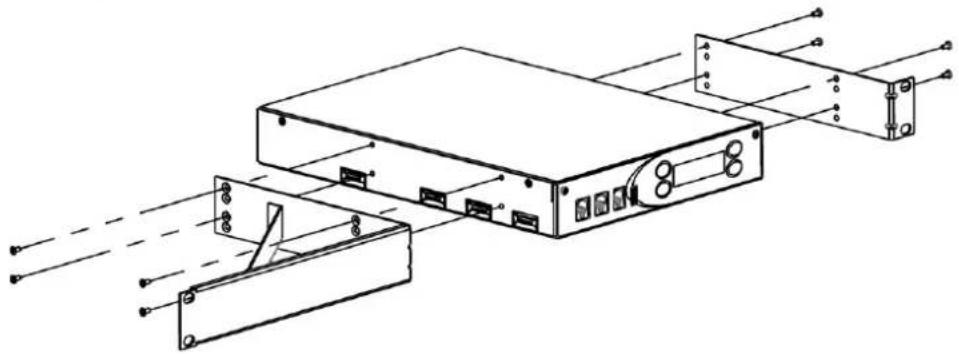
The IP-224 can be rack mounted one of two ways: one unit (single) or two units (dual). Single or dual mounting brackets are available for purchase.

Notice!
The mounting brackets ship with (14) 6-32 x 14 " flathead screws and four 10-32 x 34 " rack screws.
To assemble one IP-224 unit, do the following:
-
Using four screws, attach the side bracket to the right side of the unit.
-
Using four screws, attach the side bracket to the left side of the unit.
-
Using four screws, attach the side bracket to the right side of the unit.
- Using four screws, attach the side bracket to the left side of the unit.
natural_image
Technical line drawing of an electronic device with internal components and wiring (no text or symbols)To assemble two IP-224 units, do the following:
- Using four screws, attach the middle bracket (C) to the left side of the unit #2 (B).
-
Using four screws, attach the side bracket (D) to the right side of the unit #2 (B).
-
Using two screws, attach the middle bracket (C) to the bottom of the unit #1 (A).
- Using four screws, attach the side bracket (D) to the left side of the unit #1 (A).

To mount the assembled unit to the rack, do the following:
- Place the assembly in the rack and align the side brackets holes with the rail's holes.
- Using four screws, attach the assembly's side brackets to the rail.

natural_image
Technical line drawing of a server rack unit with mounting brackets and ventilation slots (no text or symbols)6 Connection
6.1 Front Panel Connections
For more information, see Controls and Indicators, page 12.
- For an electrically safe installation, the external power supply must be UL listed and CSA approved.
- All cables must not exceed three (3) meters in length.
RADIO 1 and RADIO 2 Jack
The front panel RADIO1 and RADIO2 jacks are used to measure receive and transmit audio levels of the specified line. Fluke Banjo P/N 10220-100 or a similar device can be used to take measurements.
To connect a voltmeter to the IP-224, do the following:
On the front of the IP-224 unit, insert the RJ-12 connector into the LINE jack.
| Pin Number Description Banjo | Pin | |
| 1 CTCSS/Spare Audio Input 1 | ||
| 2 RX Audio BK | ||
| 3 TX- Audio R | ||
| 4 TX+ Audio G | ||
| 5 Ground Y | ||
| 6 CTCSS/Spare Audio Output 6 |
Table 6.1: RJ-12 Pinouts
HANDSET Jack
The HANDSETJack is used to connect an optional handset, (AHS-1) allowing the user to monitor and talk on either line. When the handset PTT (Push-To-Talk) is pressed, the selected radio connected to the IP-224 is keyed up on the existing frequency and the handset microphone audio is transmitted.
Ethernet audio is also generated on the TX multicast and port for the selected line. This functionality can be used to test both the Ethernet network and the analog connection.
| Pin Number Description | |
| 1 | Microphone Audio Input |
| 2 | Ground |
| 3 | PTT Input |
| 4 | Speaker Audio Output |
Table 6.2: Handset Jack Pinouts
6.2 Back Panel Connections
Power Terminal
The Power Terminal is used to connect power (+11VDC to +16VDC) to the unit using a 3-pin terminal.
To connect power to the IP-224, do the following:
Using the 3-Pole Terminal Strip Connector, connect Pin 1 to +12VDC, Pin 2 to ground, and Pin 3 to earth ground.
| Pin Number Description | |
| 1 +12V | |
| 2 GND | |
| 3 EGND |
Table 6.3: Power Terminal Pinouts
PRIM Port
The PRIM port is used to connect the IP-224 to the Radio Dispatch primary network.
To connect to the network, do the following:
Insert one end of the Ethernet cable into the PRIM Port and the other end in the network router.
The IP-224 LINK LED illuminates
SECOND Port
The SECOND port is an optional Ethernet connection. It can be used to connect to a backup network router. If the primary Ethernet connection fails, the IP-224 can automatically switch over to the secondary connection.

Notice!
The SECOND Port is supported in version 1.300 or newer software releases.
To connect to a backup network, do the following:
Insert one end of the Ethernet cable into the SECOND Port and the other end into the backup network router.
ACCESSORY Port
The ACCESSORY port connector is used for recorder outputs. The user has the option to route analog signals out of the IP-224 to interface to a third-party recorder.
| Pin Number Pin Name Description | ||
| 1 Recorder Line 1 | Output+ | 20mVpp to 8Vpp Adjustable (Balanced) |
| 2 N/C | ||
| 3 N/C | ||
| 4 N/C | ||
| 5 Ground | ||
| 6 Recorder Line 1 | Output- | 20mVpp to 8Vpp Adjustable (Balanced) |
| 7 N/C | ||
| Pin Number Pin Name Description | ||
| 8 Recorder Line 2 | Output+ | 20mVpp to 8Vpp Adjustable (Balanced) |
| 9Recorder Line 2 | Output- | 20mVpp to 8Vpp Adjustable (Balanced) |
Table 6.4: Accessory DB-9 Pinout
DB-37 Port
The DB-37 port is used to connect a radio interface cable enabling the associated radio to communicate with the IP-224. Each port connects one radio to one line.
| Pin Number Pin Name Description | ||
| 1 TX+ Audio 20mVpp to 40Vpp | Adjustable | (Balanced) |
| 2 TX- Audio 20mVpp to 40Vpp | Adjustable | (Balanced) |
| 3 CTCSS/Spare Audio Output | 10mVpp to 10Vpp Adjustable | |
| 4 RSSI Input | a | User selectable 5/10 VDC Maximum |
| 5 PTT Relay Common Contact 1 | Amp @ 63 V AC/DC | |
| 6 MON Relay N.C. Contact 1 Amp | @ 63 V AC/DC | |
| 7 Mon Relay N.O. Contact 1 Amp | @ 63 V AC/DC | |
| 8 Function #1 Relay Common | Contact | 1 Amp @ 63 V AC/DC |
| 9 Function #2 Relay N.C. | Contact | 1 Amp @ 63 V AC/DC |
| 10 Function #2 Relay N.O. | Contact | 1 Amp @ 63 V AC/DC |
| 11 Digital I/O #0 ±36VDC Withstanding Rating | ||
| 12 Digital I/O #2 ±36VDC Withstanding Rating | ||
| 13 Digital I/O #4 ±36VDC Withstanding Rating | ||
| 14 Digital I/O #6 ±36VDC Withstanding Rating | ||
| 15 COR Input | ±36VDC Withstanding Rating | |
| 16 RS-485/CAN D+ | ±5VDC Maximum | |
| 17 RS-232/TTL TXD | RS-232 - Voltage Range: ±25 | VDC MaximumTTL - Voltage Range: 0 to +5VDC Maximum |
| Pin Number Pin Name Description | ||
| 18 USB VBus/+5VDC Output +5VDC, 1 Amp output | (maximum) | |
| 19 USB D+ +5VDC Maximum | ||
| 20 RX+ Audio 10mVpp to 10Vpp Adjustable | (Balanced) | |
| 21 RX- 10mVpp to 10Vpp Adjustable | (Balanced) | |
| 22 CTCSS/Spare Audio | a | 10mVpp to 10Vpp Adjustable |
| 23 PTT Relay N.C. Contact 1 Amp @ 63 V AC/DC | ||
| 24 PTT Relay N.O. Contact 1 Amp @ 63 V AC/DC | ||
| 25 MON Relay Common Contact 1 Amp @ 63 V AC/DC | ||
| 26 Function #1 Relay N.C. | Contact | 1 Amp @ 63 V AC/DC |
| 27 Function #1 Relay N.O. | Contact | 1 Amp @ 63 V AC/DC |
| 28 Function #2 Relay Common | Contact | 1 Amp @ 63 V AC/DC |
| 29 Ground | ||
| 30 Digital I/O #1 ±36VDC Withstanding Rating | ||
| 31 Digital I/O #3 ±36VDC Withstanding Rating | ||
| 32 Digital I/O #5 ±36VDC Withstanding Rating | ||
| 33 Digital I/O #7 ±36VDC Withstanding Rating | ||
| 34 RS-485/Busy ±5VDC Maximum | ||
| 35 RS-485/CAN D- ±5VDC Maximum | ||
| 36 RS-232/TTL RXD RS-232 - Voltage Range: ±25 | VDC MaximumTTL - Voltage Range: 0 to+5VDC Maximum | |
| 37 USB D- | ±5VDC Maximum | |
Table 6.5: DB-37 Port
Input is not supported in any firmware version
7 Configuration
7.1 Browser Setup
The IP-224 configuration windows are accessed by using a web browser such as Microsoft Internet Explorer1 version 8.0 or later, Mozilla1 Firefox version 4.00 or later, or Google Chrome. Access to the IP-224 configuration pages is password protected. This chapter includes information on setting the IP Address, accessing the IP-224 web interface pages, the IP-224 web page setup standards, and an explanation of the IP-224 web page configuration parameters.
This section provides the user with the required information to set up a basic radio installation. Some modes of operation and adjunct connected equipment trigger various configuration pages to display additional information. Refer to the specific technical manuals and application notes for supplementary information. Alternatively, TSM (Telex System Manager) can be used to set most IP-224 parameters.

Notice!
Setting the IP-224 network parameters can also be done using the front panel controls. For more information, see
7.1.1 Setting the IP Address Information
The IP Addresses of the IP-224 and the PC must be on the same Subnet in order for the IP-224 to interface successfully with the LAN or WAN. IP Addresses consist of four numbers (i.e. quads) separated by periods. For example, 10.2.99.101.
An example of IP Addresses residing in the same Subnet:
| PC IP Address - 10.2.99.250 | |
| IP-224 Address - 10.2.99.251 | |
| PC and IP-224 Subnet Mask - 255.255.255.0 |
NOTE:
- Contact your Network Administrator to obtain the network IP Address and Subnet Mask.
- For operation on different Subnets, a default gateway address must be configured. For more information, see
- IP-224 supports IPv6 addressing for device configuration. Please contact your network administrator to obtain the IPv6 address and the subnet prefix length.
7.1.2 IP-224 Web Browser Configuration
Before connecting the IP-224 to the web browser, an IP Address and Subnet Mask, compatible with an existing network, must be set on the IP-224. For more information, see Network Settings, page 94.
The configured IP Address is the web browser address (https://[IP Address]) used to access the IP-224 configuration windows.
NOTE:
- A web browser security exception may be required to access the IP-224.
- The web browser user account will timeout after 15 minutes of inactivity.
- The default username is admin and the default password is admin.
- < > & “‘ { } / \ special characters are not allowed in the web browser.
- Web browser configuration text fields cannot be blank. The web browser user account will be locked out after five failed login attempts. The user has to wait 15 minutes to be able to login again.
To access the IP-224 configuration windows, do the following:
- Open a web browser on the PC.
- In the web address bar, enter the IP Address of the IP-224. The IP-224 configuration Login window appears.


- In the Username field, enter the username.
- In the Password field, enter the appropriate password.

Notice!
If this is the first time the IP-224 has been started and/or a username or password has not been assigned to the unit, enter admin for both the username and password.
3. Click the OK button.
The Home window appears.
To logout from the IP-224 configuration windows, do the following:
▶ Click the Logout button.
7.1.3 Web Setup Windows Standards
The left navigation pane contains links used to access the various IP-224 configuration windows.
| Button Description | |
| Home | Displays the Home Window |
| Ethernet Setup | Displays the Ethernet Setup Window |
| Multicast Setup | Displays the Multicast Setup Window |
| Hardware Setup | Displays the Hardware Setup Window |
| Gain Setup | Displays the Gain Setup Window |
| Per Line Setup | Displays the Per Line Setup Window |
| Crosspatch Setup | Displays the Crosspatch Setup Window |
| Account Management | Displays the Account Management Window |
| Backup & Restore | Displays the Backup & Restore Window |
| Firmware Upgrade | Displays the Firmware Upgrade Window |
| Additional Features | Displays the Additional Features Window and Access Key Entry Field |
| Save Parameters | Displays the Save Parameters or Reset IP-224 |
| System Status | Displays the System Status Window |
Table 7.6: IP-224 Left Navigation Buttons
To access a setup window, do the following:
▶ Click the appropriate link.
7.1.4 IP-224 Browse Banner
The IP-224 Browser Banner appears on all windows in the web configuration. The upper left corner displays the IP-224 unit's information label.
This label contains the following information:
Name The IP-224 Name
MAC The IP-224 MAC Address
HW The IP-224 Hardware Version
FW The IP-224 Firmware Version
SN The IP-224 Serial Number
Checksum A value calculated from the firmware programmed in the unit.
7.1.5 Home Window
The Home window provides the user contact information.
Device Name Field
The DeviceName field is used to enter a user-defined descriptive name (40 characters max) for the unit. This name is displayed in the upper left corner of each IP-224 configuration page in the Browser Banner.
Submit Button
The Submit button is used to temporarily save changes to the IP-224.
To permanently save changes, do the following:
- Click the Submitbutton.
The changes are sent to the IP-224 to temporary storage. - From the left navigation, select SaveParameters.
The Save Parameters window appears. - Click the SaveParametersbutton.
Changes are now permanently saved to the IP-224 console.
7.2 Ethernet Setup
The Ethernet Setup window is used to enable Auto Failover, view the Current Active Port, set an active port, configure a network connection for the Primary Port or Secondary Port by configuring the host protocol, the IP-224's IP Address, Subnet Mask, Gateway Address, Ping IP Address, Ping Count, Ping Timeout, Time Between Pings, IPv6 Setup, Packet Delay Before Playback, QOS settings, SNMP settings, and TSM (Telex System Manager) settings. TSM is used to set parameters and update firmware for the IP-224.
Use the navigation pane on the left to open the following windows:
- IPv6 Setup
- Packet Setup
- CMS Setup
- SNMP Setup
- TSM Setup
- Ethernet Port Setup

Figure 7.1: Ethernet Setup Window (1 of 2)

Figure 7.2: Ethernet Setup Window (2 of 2)
7.2.1 Ethernet Port Setup
Auto Failover Enabled Check Box
The Auto Failover Enabled check box, if selected, enables the IP-224 to ping a network IP Address with the Primary or Secondary Ethernet port. When the IP-224 boots, it sets the Primary Ethernet port as active. If the Auto Failover is enabled, the IP-224 pings the Primary Ethernet port's Ping IP Address. If the ping fails with the Primary Ethernet port, the IP-224 switches to the Secondary Ethernet port. The IP-224 continues using the secondary Ethernet port until the ping fails on the secondary network, the port selection is changed via the web page/display, or the IP-224 is rebooted.
The Auto Failover can also be changed via the front panel of the IP-224. This is the ping command with the fields described in the sections below:
Ping-c

Notice!
Validate the Primary Port and Secondary Port Ping IP Addresses when enabling Auto Failover. If neither the Primary nor the Secondary Ping IP Address can be pinged successfully, the Active Port will continuously switch between the Primary and Secondary Ethernet ports. This will lead to an unreliable network connection to the IP-224.
Current Active Port Field
The Current Active Port field is used to view the IP-224's current active Ethernet port. This field is automatically populated and cannot be modified.

Notice!
The Current Active Port can also be seen on the System Status web page or via the front panel display line selection icon where an asterisk (*) indicates the Primary Ethernet port is active and a pound sign (#) indicates the Secondary Ethernet port is active.
Set Active Port Radio Button
The Set Active Port radio button is used to manually select the active Ethernet port on the IP-224. The active port can be changed regardless of the Auto Failover Enabled setting (for debug/setup purposes).
Available selections are:
Primary — Select Primary to set the PRIM Ethernet port on the IP-224 as the active port (Default).
Secondary — Select Secondary to set the SECOND Ethernet port on the IP-224 as the active port.
Primary Port Column
The Primary Port column is used to enable DHCP, set the unit's IP Address, Subnet Mask, Gateway, Ping IP Address, Ping Count, Ping Timeout, and Time Between Pings for the PRIM Ethernet port on the IP-224.
Secondary Port Column
The Secondary Port column is used to enable DHCP, set the unit's IP Address, Subnet Mask, Gateway, Ping IP Address, Ping Count, Ping Timeout, and Time Between Pings for the SECOND Ethernet port on the IP-224.
DHCP Enabled Check Box
The DHCP Enabled check box, if selected, allows the IP-224 to acquire IP Addresses and other network configuration settings automatically when connected to a network.

Notice!
The network must allow DHCP service before the IP-224 can get the network parameters. Radio Dispatch does not recommend operating with DHCP enabled. Operating with DHCP enabled may cause the base IP Address to change unexpectedly, making changes to the software setup more difficult.
Unit IP Address Field
The Unit IP Address field is used to display or set the unit's IP Address. The web browser configuration uses the IP Address to identify the IP-224 for such operations as set up, software upgrades, and communication on the network.
Subnet Mask Field
The Subnet Mask field is used to display or set the unit's Subnet Mask Address. The Subnet Mask is used to distinguish local addresses from addresses requiring the use of a gateway to reach other networks. Contact your Network Administrator to obtain the proper value for this field.
Default Gateway Field
The Default Gateway field is used to display or set the unit's gateway address. The gateway address is used to connect to another network.
Ping IP Address Field
The Ping IP Address field is used, when Auto Failover is enabled, to set the network IP Address used in the ping command to determine if the IP-224 needs to switch Ethernet ports. If the network IP Address is unreachable, the ping command fails, and the IP-224 switches Ethernet ports.
The Ping IP Address can be changed via the front panel of the IP-224.
Ping Count
The Ping Count field is used, when Auto Failover is enabled, to set the number of ping attempts used in the ping command to determine if the IP-224 needs to switch Ethernet ports.
The IP-224 attempts to ping the network IP Address the number of times configured in the Ping Count field. If the Ping IP Address is unreachable for ALL ping attempts, the ping command fails, and the IP-224 will switch Ethernet ports.
The range for this field is 1 to 10.
The Ping Count can also be changed via the front panel of the IP-224.

Notice!
The ping command inserts a 1 second delay between each ping attempt when the Ping IP Address is unreachable. For example, if the Ping Count is set to 5, the ping command requires a minimum of 4 seconds to complete for an unreachable Ping IP Address.
Ping Timeout
The Ping Timeout field is used, when Auto Failover is enabled, to set the timeout in seconds that is used to cancel the ping command. The timeout is started after all the Ping Count attempts have been sent. If the timer expires and the ping command is still active, it cancels the ping command. If ALL ping attempts failed before the ping command was cancelled, then the IP-224 switches Ethernet ports.
The range for this field is 1 to 20 seconds.
The Ping Timeout can also be changed via the front panel of the IP-224.

Notice!
There is a 1 second delay between each ping attempt. The ping command is cancelled in (Ping Count - 1) seconds plus Ping Timeout seconds when the Ping IP Address is unreachable. For example, the Ping Count is set to 5 and the Ping Timeout is set to 10, the ping command is cancelled in 14 seconds for an unreachable Ping IP Address.
Time Between Pings
The Time Between Pings field is used, when Auto Failover is enabled, to set the amount of time in seconds between ping commands. When a ping command completes, either successfully or unsuccessfully, this is the amount of time before the next ping command is executed.
The range for this field is 5 to 60 seconds.
The Time Between Pings can also be changed via the front panel of the IP-224. For more information, see Network Settings, page 94.
Auto Failover Web Page Setup
To configure the IP-224, do the following:
-
Open the IP-224 web application.
-
From the left navigation, select Ethernet Setup.
The Ethernet Setup window appears.
- Select the Auto Failover Enabled checkbox.

Notice!
The IP-224 always selects the Primary Port at power up.
- In the Primary Port and Secondary Port fields, enter the Ping IP Address.

Notice!
Verify the network IP Addresses are reachable on the corresponding Primary and Secondary network.
-
In the Primary Port and Secondary Port fields, enter the Ping Count.
-
In the Primary Port and Secondary Port fields, enter the Ping Timeout.
- In the Primary Port and Secondary Port fields, enter the Time Between Pings.
7.2.2 IPv6 Setup
IPv6 Enable Check Box
The IPv6 Enable check box, if selected allows the IP-224 to be addressed and configured using IPv6.
Link Local Address Field
The Link Local Address field is a 128-bit address field. It is not editable. It is an auto-configured address field and starts with FE in hexadecimal. The link local address is used to route the local network device only and cannot be routed to public networks. The link local address is generated from a local device MAC address.

Notice!
The Link Local Address text next to the field is a direct link. Click the text to go directly to the web page configuration of the device.
Unit IP Address Field
The Unit IP Address field is used to display or set the unit's IPv6 Address. The web browser configuration uses the IPv6 Address to identify the IP-224 for such operations as setup and communication on the network. The IPv6 address size is 128 bits and is represented in hexadecimal format. The 128-bit address is divided into eight 16-bit blocks. Each 16-bit block is converted to a 4-digit hexadecimal number and is separated by colons.

Notice!
The Unit IP Address text next to the field is a direct link. Click the text to go directly to the web page configuration of the device.
Subnet Prefix Length Field
The Subnet Prefix Length field is used to identify how many bits of the global IPv6 address are used for the network portion. The prefix length in IPv6 corresponds to the subnet mask field used in IPv4. However, rather than being express in four octets like in IPv4, it is expressed as an integer between 1 through 128.
The default for this field is 64.
Gateway Field
The Gateway field is used to configure the unit's gateway IPv6 Address similar to IPv4 setting. It is used to connect the device to another network.
7.2.3 Packet Setup
Packet Delay Before Playback Field
The Packet Delay before Playback field is used to enter a delay period for the audio packets before they are played. The IP-224 uses a 20ms UDP/IP packet to encode audio. Some buffering of these packets must occur before playback to help absorb network delays, jitter, and lost packets.
The range for this field is 4 to 29.
The typical entry for this field is 10, which translates to a delay of 200ms before playback (each packet is 20ms of audio). Larger values may be required for complicated networks, and smaller values for less complicated networks.
QOS Precedence Bits Field
The QOS (Quality of Services) Precedence Bits field is used to set the priority level of network traffic.
The range for this field is 0 to 7.
Typically, this value is set to 0 for normal voice traffic.
QOS D, T, and R Bits Field
The QOS: D, T, and R Bits field is used for advanced programming purposed. Contact your Network Administrator to obtain the appropriate value for this field.
- Delay (D) - An active delay bit directs the router to choose a high speed to minimize delay.
- Throughput (T) - An active throughput bit specifies that high capacity lines should be used.
- Routing (R) - An active routing bit directs routing protocols and network management applications to select fault tolerant paths.
The range for this field is 0 to 7. Typically, this value is set to 0.
| Precedence Field D, T, and R bits | ||||||
| Binary Traffic Type Binary | ||||||
| 0 0 0 (0) Best Effort D T R | ||||||
| 0 0 1 (1) Background 0 0 0 (1) Normal (Best Effort), minimal cost | ||||||
| 0 1 0 (2) Standard 0 0 1 (2) Maximize Reliability | ||||||
| 0 1 1 (3) Excellent Load 0 1 1 (3) Maximize Throughout | ||||||
| 1 0 0 (4) Controlled Load | 1 0 0 (4) Minimize Delay | |||||
| 1 0 1 (5) Video | ||||||
| 1 1 0 (6) Voice | ||||||
| 1 1 1 (7) Network Control | ||||||
Table 7.7: Precedence Field and D, T, R Binary Reference
7.2.4 CMS Setup
IP Address Field
Use the IP Address field to enter the IP address of CMS server. IP-224 will connect to the CryptoSync service of CMS to request and sync encryption keys.
Control Port Field
Use the Control Port field to enter the port of CMS Atlas service. IP-224 will connect to this port to request for CryptoSync service port.
SRTP Encryption Check Box
The SRTP Encryption check box enables encryption and decryption of the audio going in and coming out on two lines from the IP-224.

Notice!
If SRTP is enabled, the IP Recorder is disabled.
By default, SRTP Encryption is not enabled.
Authorization Token Field
The Authorization Token field displays the token string used as an authorization password for the IP-224 to connect to CryptoSync service of CMS. This must match with the CryptoSync setting of CMS.
7.2.5 SNMPv3 Setup

Notice!
IP-224 only supports SNMPv3.
SNMPv3 Enable Check Box
The SNMPv3 Enable check box allows third party SNMP clients to connect and query information from the IP-224. For more information, see the Application Guide Simple Network Management Protocol (SNMP) for IP-224.

Notice!
Current SNMP MIB files can be found in the latest IP-224 firmware folder located on the product CD shipped with the unit.
Username Field
The Username field displays the username the SNMP client uses to connect to the IP-224. By default, the username is set to "admin" and cannot be modified.
Auth Password Field
Use the Auth Password to protect the IP-224 from unauthorized access. The SNMP client uses this password to connect to SNMP of the IP-224.

Notice!
If using SNMP, changing the default authorization password is recommended. The password must be at least 8 characters.
Privacy Password Field
Use the Privacy Password field to encrypt SNMPv3 messages between the IP-224 and the SNMP clients.

Notice!
If using SNMP, changing the default privacy password is recommended. The privacy password must be at least 8 characters.
Change Password Button
The Change Password button is used to modify the authorization and privacy passwords.
Trap Target 1 - 3 Enable Check Box and IP Address Field
Use Trap TargetsTrap Targets to send special messages to the trap receiver in case of events that happen. IP-224 supports up to three trap targets.
Use the Trap Target 1 - 3 Enable check box to enable or disable trap targets.
The Trap Target 1 - 3 IP Address field displays the IP address of the trap receiver.
7.2.6 Telex System Manager Setup
Enable Check Box
Use the Enable check box to enable communications with TSM (Telex System Manager). If cleared, TSM cannot detect the IP-224.
By default, the check box is selected.
For more information, see Firmware Upgrade, page 76.
For more information on Telex System Manager, refer to the Telex System Manager Technical Manual (F.01U.261.900).
Multicast Address Field
The Multicast Address field displays the default Multicast Address used by TSM to detect connected VoIP hardware.
Incoming Port Field
The Incoming Port field displays the port used to communicate with TSM. TSM requests data from the IP-224 through this port.
Outgoing Port Field
The Outgoing Port field displays the port used to communicate with TSM. The IP-224 sends data through this port to TSM.
TTL Field
The TTL field is used to enter the number of routers the multicast packets pass through before being discarded.
The range for this field is 1 to 128.
Default is 6.
Submit Button
Use the Submit button to temporarily save changes to the IP-224.
To permanently save changes, do the following:
- Click the Submit button.
The changes are sent to the IP-224 in temporary storage. - From the left navigation, select Save Parameters.
The Save Parameters window appears. - Click the Save Parameters button.
Changes are now permanently saved to the IP-224 console.
7.3 Multicast Setup
The Multicast Setup window identifies the mode of operation (line type), serial protocol (serial type), vocoder type, in addition, which Multicast Address and ports are used for the IP-224 to communicate various line and IP recorder information.
Use the navigation pane on the left to open the following windows:
- Line Setup
- IP Recorder Setup
- Line Setup - IP Recorder Setup

Figure 7.3: Multicast Setup Window
Auto Configuration
The Auto Configuration check box, if selected, the IP-224 automatically configures the necessary changes to the Hardware, Gain, and Per Line Setup parameters when a Line Type or Serial Type is selected.
7.3.1 Line Setup
Line Enable Check Box
The Line Enablecheck box, if selected, indicates DB-37 and Ethernet connectivity for the specified line is active. Otherwise, the DB-37 and Ethernet traffic for the specified line of the IP-224 is ignored.
Line Name Field
The Line Name field is used to enter a descriptive name for the specified line. This name is displayed on the front panel LCD. This field can contain up to 9 characters.
Line Type Drop Down Menu
The Line Type drop down menu is used to select the operating mode for Line 1 and 2. Selecting a Line Type enables the fields necessary to enter the setup information for the selected line. The selected Line Type determines which serial mode may be enabled.
Available selections are:
Local Mode Connects the radio directly to the IP-224 providing full control of the radio.
Serial Types:
| - EFJ 5300/VMx00 | - Kenwood x90 |
| - Hytera MD782 | - MOTOTRBO Interface |
| - Hytera MT680 | - MTRBi |
| - Icom | - PowerTrunk |
| - iDen | - Sepura |
| - Kenwood 5x10 | - Serial Over IP |
| - Kenwood NEXEDGE | - Sprint Direct Connect |
| - Kenwood NX-5x00 | - Tait TM91xx/TM94xx |
| - Kenwood VM5x30 | - Tait TM93xx |
| - Kenwood x150 | - Telex Generic |
| - Kenwood x180 | |
| - Kenwood x80 |
NOTE: All radio types are not always shown. Available selectable radio types are based on enabled options.
Tone Mode Generates the key tones required to control standard, tone-equipped radio circuits. This allows an existing tone decoder and radio to be connected. This mode also supports a parallel analog console for local control.
Serial Types:
- Serial Over IP
Console Mode Allows an analog tone console to encode/decode industry standard tones, enabling the analog tone console to control and monitor radio traffic via an IP network. Console Mode also supports 6-Wire Local E&M connections. For more information, see Console Mode, page 115.
Serial Types:
- Serial Over IP
Serial Type Drop Down Menu
The Serial Type drop down menu is used to select the serial communication type (for example, serial protocol, baud rate, etc.) for Line 1 and 2. For more information, see “Line Type Drop Down Menu” on page 48 for a list of available serial options.
Vocoder Type Drop Down Menu
The Vocoder Type drop down menu is used to select the vocoder used to convert audio into a digital format. This feature is used to configure communication between the IP-224 and C-Soft.
Available selections are shown. Bit rates are based on Simplex mode.
- TELEX 32K (50 kbits/sec with overhead)
- G.726 16K (34 kbits/sec with overhead)
- G.726 32K (50 kbits/sec with overhead)
- G.711 64K (82 kbits/sec with overhead)
Design considerations must take into account that although 16K uses less bandwidth the audio quality may not perform as desired.

Notice!
Vocoder configurations must be the same across all devices and C-Soft.
Mcast Enable Check Box
The Mcast Enable check box, if selected, indicates Ethernet connectivity for the specified line is active. Otherwise, audio received from the analog connection of the IP-224 is not echoed to the Ethernet, and Ethernet traffic is not mixed into the IP-224 audio.
RX Mcast Address Field
The RX Mcast Address field is used to enter the Broadcast Address for all audio traffic received on a specific line. All consoles wanting to listen to the audio traffic received must have the same Multicast Address.
The range for this field is 224.0.0.0 to 239.255.255.255.
NOTE:
- IP-224 units can also operate Unicast (point-to-point). These fields can support class A, B, and C addresses.
- Ensure the RX and TX port numbers are unique.
RX Port Field
The RX Port field is used to enter the RX port number for each line. The RX port number must be unique. The range for this field is 1054 to 65535.
TX Mcast Field
The TX Mcast field is used to enter the Broadcast Address for all audio traffic transmitted on a specific line. All consoles wanting to transmit audio traffic must have the same Multicast Address.
NOTE:
- IP-224 units can also operate Unicast (point-to-point). These fields can support class A, B, and C addresses.
- Ensure the RX and TX port numbers are unique.
The range for this field is 224.0.0.0 to 239.255.255.255.
TX Port Field
The TX Port field is used to enter the TX port number for each line. The TX port number must be unique. The range for this field is 1054 to 65535.
TX Group Port A Field
The TX Group Port A field is used to transmit to multiple IP-224 units based on a unique port number. The range for this field is 1054 to 65535.
TX Group Port B Field
The TX Group Port B field is used to transmit to multiple IP-224 units based on a unique port number. The range for this field is 1054 to 65535.
TTL Field
The TTL field is used to enter the number of routers the multicast audio packets go through before being discarded. Network design dictates this value.

Notice!
If audio is not reaching a particular node on the network, increasing this value may correct the problem.
The range for this field is 1 to 128.
The default is 6.
7.3.2 IP Recorder Setup
Mcast Enable Check Box
The Mcast Enable check box is used to activate the IP recorder multicast output for the specified line.
Line Name Field
The Line Name field is used to assign a unique label to the IP recorder line. This field can contain up to 15 alphanumeric characters.
Vocoder Type Drop Down Menu
The Vocoder Type drop down menu is used to select the bit rate at which audio is converted into digital format. This feature is used to configure communication between the IP-224 and Network Recorder.
Available selections are:
- TELEX 32K (50 kbits/sec with overhead)
- G.726 16K (34 kbits/sec with overhead)
- G.726 32K (50 kbits/sec with overhead)
- G.711 64K (82 kbits/sec with overhead)

Notice!
Vocoder configurations must be the same across devices and the Network Recorder
Mcast Address Field
The Mcast Address field is used to enter the Multicast Address that generates multicast audio for the IP recorder output.
The range for this field is 224.0.0.2 to 239.255.255.255.
Outgoing Port Field
The Outgoing Port field is used to enter the Multicast Audio port number for the IP recorder output.
The range for this field is 1054 to 65535.
TTL Field
The TTL field is used to enter the number of routers the multicast audio packets go through before being discarded. Network design dictates this value.
The range for this field is 1 to 128.
Submit Button
Use the Submit button to temporarily save changes to the IP-224.
To permanently save changes, do the following:
- Click the Submit button.
The changes are sent to the IP-224 in temporary storage.
- From the left navigation, select Save Parameters.
The Save Parameters window appears.
- Click the Save Parameters button.
Changes are now permanently saved to the IP-224 console.
7.4 Hardware Setup

Notice!
If the Auto Configuration check box from the Multicast Setup window is selected, the IP-224 automatically configures the hardware when a Line Type or Serial Type is chosen.
The Hardware Setup window is used to view the line information and settings. The user many also manually set the hardware parameters for special requirements determined by the installation.
Use the navigation pane on the left to open the following windows:
- Line Info
- Audio/Analog Setup
- Digital I/O Setup
- Display Setup
- Serial Protocol Setup

Figure 7.4: Hardware Setup Window
7.4.1 Line Info
The Line Info field displays the Line Name, Line Type, and Serial Type for each line. This information is pulled from the Multicast Setup window.

Notice!
No fields can be modified in this section.
7.4.2 Audio/Analog Setup
2-Wire/4-Wire Audio Drop Down Menu
The 2-Wire/4-Wire Audio drop down menu is used to select the audio interface between the IP-224 and the radio for each line.

Notice!
The TX and RX paths are separate in 4-wire mode and combined in 2-wire mode.
Available selections for this field are 4-wire and 2-wire.
RX Audio Single-Ended/Balanced Drop Down Menu
The RX Audio Single-Ended/Balanced drop down menu is used to select the RX audio input connection for each line.
Available selections for this field are Single-Ended and Balanced.
RX Audio Impedance Drop Down Menu
The RX Audio Impedance drop down menu is used to select the RX impedance for each line. Available selections for this field are 10K Ohms, 10 Ohms, and 600 Ohms.
TX Audio Single-Ended/Balanced Drop Down Menu
The TX Audio Single-Ended/Balanced drop down menu is used to select the TX audio output connection for each line.
Available selections for this field are Single-Ended and Balanced.
TX Audio Impedance Drop Down Menu
The TX Audio Impedance drop down menu is used to select the TX impedance for each line. Available selections for this field when TX Audio Single-Ended is selected are 800 Ohms, and 200 Ohms.
Available selections for this field when TX Audio Balanced is selected are 2.4K Ohms, 1.8K Ohms, 1.2K Ohms, and 600 Ohms.
7.4.3 Digital I/O Setup
I/O Pullup/Pulldown/Float Drop Down Menu
The I/O Pullup/Pulldown/Float drop down menu is used to select the idle status on the digital I/O lines. The I/O lines can be configured with a pull-up resistor to the selected I/O voltage, a pull-down resistor to ground, or left floating.
Available selections for this field are Float, Pullup and Pulldown.
I/O Voltage Drop Down Menu
The I/O Voltage drop down menu is used to select the I/O pull-up voltage level on the digital I/O lines.
Available selections for this field are 12VDC I/O, 5VDC I/O and 3.3VDC I/O.
7.4.4 Display Setup
Contrast Drop Down Menu
The Contrast drop down menu is used to select contrast level of the unit's display. The range for this field is 1 to 15.
Menu Enable Check Box
The Menu Enable check box is used to enable/disable the accessibility of the menu from the front panel of the IP-224.
7.4.5 Serial Protocol Setup
Serial Type Drop Down Menu
The Serial Type drop down menu is used to select the IP-224 serial port protocol and voltage levels.
Available selections for this field are TTL, RS-232, RS-485, and CAN.
Baud Rate Drop Down Menu
The Baud Rate drop down menu is used to select the serial communication baud rate.
Available selections for this field:
| 300,N,8,1 | 4800,E,7,1 |
| 300,N,8,2 | 9600,N,8,1 |
| 300,E,7,1 | 9600,N,8,2 |
| 1200,N,8,1 | 9600,E,7,1 |
| 1200,N,8,2 | 19200,N,8,1 |
| 1200,E,7,1 | 19200,N,8,2 |
| 2400,N,8,1 | 19200,E,7,1 |
| 2400,N,8,2 | 38400,N,8,1 |
| 2400,E,7,1 | 38400,N,8,2 |
| 4800,N,8,1 | 38400,E,7,1 |
| 4800,N,8,2 |
RS485 Address Drop Down Menu
The RS-485 Address drop down menu is used to select the address of the attached device on the RS-485 bus the IP-224 communicates with. This is only used if RS-485 is selected as the serial communication protocol.
Available selections are 2 - 7.
Serial Protocol Version Drop Down Menu
The Serial Protocol Version drop down menu is used to select the version of the Telex Generic Serial Type. This is only displayed if Telex Generic Serial Type is selected on the Multicast Setup web page and the Advanced Interface Option (North American) or Advanced Interface Options (Export) is enabled.
Available selections are Version 1 or Version 2.
Submit Button
Use the Submit button to temporarily save changes to the IP-224.
To permanently save changes, do the following:
- Click the Submit button.
The changes are sent to the IP-224 in temporary storage.
- From the left navigation, select Save Parameters.
The Save Parameters window appears.
- Click the Save Parameters button.
Changes are now permanently saved to the IP-224 console.
7.5 Gain Setup
The Gain Setup window is used to adjust gain levels for Analog Recorder Gains, CTCSS Gains, Handset Gains, RX AGC Gains, and RX/TX Gains.
Use the navigation pane on the left to open the following windows:
- Line Info
- Analog Recorder Gains
- CTCSS Gains
- Handset Gains
- RX AGC Gains
- RX/TX Gains

bar
| Line Name | Line 1 (dB) | Line 2 (dB) | | :--- | :--- | :--- | | Gain Name | -30 | -30 | | Analog Recorder Output: | -30 | -30 | | CTCSS GAINS | -40 | -5 | | Gain Name | -15 | -15 | | CTCSS Input: | -15 | -15 | | Handset Mic Input: | 0 | 0 | | Handset Sidetone: | 0 | 0 | | Gain Name | -12 | -12 | | Handset Output: | -12 | -12 | | RX AGC GAINS | -12 | -12 | | Gain Name | -30 | -30 | | RX AGC Enabled: | -30 | -30 | | RX AGC Target Level: | 0 | 0 | | RX AGC Min Level: | -30 | -30 | | RX AGC Max Gain: | 10 | 10 | | RX / TX GAINS | -25 | -25 | | Gain Name | 0 | 0 | | RX IP Input: | 0 | 0 | | RX Input: | 0 | -5 | | TX IP Input: | -30 | -30 | | TX Monitor Input: | 0 | 0 | | TX Output: | -25 | 8 | Submit Auto Configuration: Auto Setup: Admin Logout Home Ethernet Setup Multicast Setup Hardware Setup Gain Setup Line Info Analog Recorder Gains CTCSS Gains Per Line Setup Crosspatch Setup Account Management Backup & Restore Firmware Upgrade Additional Features Save Parameters System StatusFigure 7.5: Gain Setup Window
7.5.1 Line Info
The Line Info field displays the Line Name, Line Type, and Serial Type for each line. This information is pulled from the Multicast Setup window.
These fields are automatically populated and cannot be modified.
7.5.2 Analog Recorder Gains
Analog Recorder Output Gain Slider
The Analog Recorder Output Gain slider is used to set the analog recorder output gain level for the specified line.
The range for this field is -30dB to 15dB.
7.5.3 CTCSS Gains
CTCSS Input Gain Slider
The CTCSS Input Gain slider is used to set the CTCSS/Spare Input level for the specified line. The range for this field is -15dB to 45dB.
CTCSS Output Gain Slider
The CTCSS Output Gain slider is used to set the CTCSS/Spare Output level for the specified line. The range for this field is -40dB to 15dB.
7.5.4 Handset Gains
Handset Mic Input Gain Slider
The Handset Mic Input Gain slider is used to set the gain level for the handset's microphone. The range for this field is -8dB to 20dB.
Handset Sidetone Gain Slider
The Handset Sidetone Gain slider is used to set the level of sidetone heard in the handset. Sidetone is sound diverted from a microphone to the ear piece so a speaker hears their own voice.
The range for this field is -10dB to 8dB.
Handset Output Gain Slider
The Handset Output Gain slider is used to set the handset's receive gain level for the specified line.
The range for this field is -12dB to 10dB.
7.5.5 RX AGC Gains
RX AGC Enabled Check Box
The RX AGC Enabled (Receive Automatic Gain Control) check box indicates radio RX audio includes an AGC. If selected, an AGC step is added to the line RX audio. This results in a more consistent radio RX audio by increasing the level of soft audio and decreasing the level of loud audio.
RX AGC Target Level Slider
The RX AGC Target Level slider is used to control the level at which the AGC attempts to hold RX audio. The AGC increases the level of RX audio below the Target Level, and decreases the level of RX audio above the Target Level.
The range for this field is -12dB to 2dB.
RX AGC Enabled Check Box
The RX AGC Enabled (Receive Automatic Gain Control) check box indicates radio RX audio includes an AGC. If selected, an AGC step is added to the line RX audio. This results in a more consistent radio RX audio by increasing the level of soft audio and decreasing the level of loud audio.
RX AGC Target Level Slider
The RX AGC Target Level slider is used to control the level at which the AGC attempts to hold RX audio. The AGC increases the level of RX audio below the Target Level, and decreases the level of RX audio above the Target Level.
The range for this field is -12dB to 2dB.
7.5.6 RX/TX Gains
RX IP Input Gain Slider
The RX Input Gain slider is used to set the input receive multicast gain level for the specified line. The slider only enables when the line type is set to Console Mode.
The range for this field is -30dB to 10dB.
TX IP Input Gain Slider
The TX IP Input Gain slider is used to set the inbound transmit multicast gain level for the specified line. The range for this field is -30dB to 10dB.
TX Monitor Input Gain Slider
The TX Monitor Input Gain slider is used to set the transmit monitor audio gain level for the specified line. The range for this field is -30dB to 38dB.
TX Output Gain Slider
The TX Output Gain slider is used to set the transmit audio gain level for the specified line. The range for this field when TX Audio Single-ended is selected is -40dB to 20dB.
The range for this field when TX Audio Balanced is selected is -35dB to 30dB.
Submit Button
Use the Submit button to temporarily save changes to the IP-224.
To permanently save changes, do the following:
- Click the Submit button.
The changes are sent to the IP-224 in temporary storage.
- From the left navigation, select Save Parameters.
The Save Parameters window appears.
- Click the Save Parameters button.
Changes are now permanently saved to the IP-224 console.
7.6 Per Line Setup
The Per Line Setup window, is used to view and set the parameters for the selected line. The details on the window apply to Line 1 or 2.

Notice!
If the field is grayed out or missing, it is not applicable to the mode selected for the line.
Use the navigation pane on the left to open the following windows:
- Line Info
- CTCSS Setup
- Delay/Timeout Setup
- Ethernet Crossmute Setup
- Function Tone Setup
- LAM/COR Setup
- Options Setup
- Relay Setup
- Signaling Setup
- Tone Setup
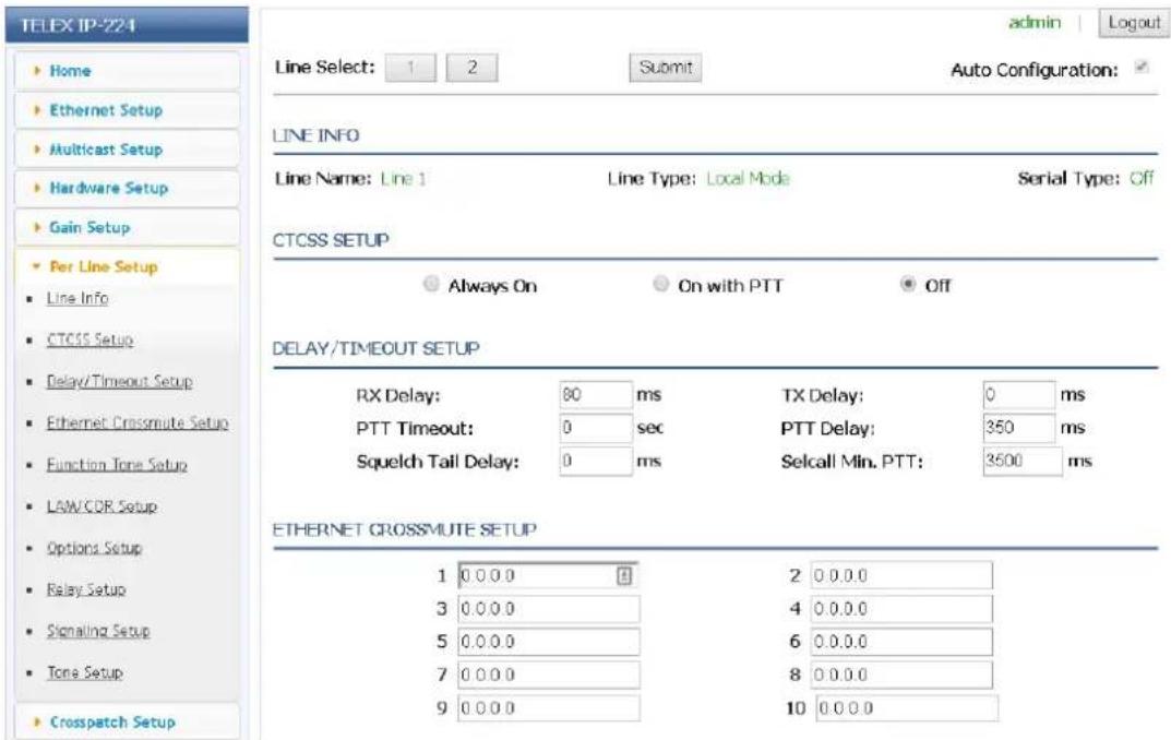
Figure 7.6: Per Line Setup Window
7.6.1 Line Info
The Line Info field displays the Line Name, Line Type, and Serial Type for each line. This information is pulled from the Multicast Setup window.
These fields are automatically populated and cannot be modified.
7.6.2 CTCSS Setup
Always On Radio Button
The Always On radio button, if selected, indicates CTCSS is on at all times.
On With PTT Radio Button
The On With PTT radio button, if selected, indicates CTCSS is generated only when PTT is activated.
Off Radio Button
The Off radio button, if selected, indicates CTCSS is off at all times.
By default, the Off radio button is selected.
7.6.3 Delay/Timeout Setup
RX Delay Field
The RX Delay field is used to enter the amount of time, in milliseconds, the RX audio is recorded and stored. RX audio is constantly recorded by the IP-224 and when a COR or LAM triggered detect occurs, the IP-224 goes back the specified time of delay to start generating Ethernet packets. This provides the ability to prevent lost first syllables.
The rand for this field is 0 to 5000ms.
TX Delay Field
The TX Delay field is used to enter the delay of TX audio. When TX Ethernet packets arrive, the PTT relay is closed and TX audio is delayed for the specified time. This provides the ability to overcome timing issues involving repeater attack time or trunking (clear to talk) delays.
The range for this field is 0 to 2000ms.
PTT Delay Field
The PTT Delay field is used to enter the amount of time the PTT Relay closure is delayed allowing for the TX Ethernet packets arrive.
The range for this field is 0 to 5000ms.
Squelch Tail Delay Field
The Squelch Tail Delay field is used to enter the amount of time the RX audio is muted after PTT is released. This provides the ability to overcome squelch tail ping-pong in crosspatch modes by muting the radio RX input after PTT is released.
The range for this field is 0 to 5000ms.
Selcall Min. PTT Field
The Selcall Min. PTT field is used to enter the minimum amount of time serially controlled radios will PTT after receiving a Selcall, Individual Call, or Group Call from IP dispatch consoles.
The range for this field is 1000 to 10,000ms.

Notice!
The Selcall Min. PTT field is displayed only if Local Mode is selected in the Line Type drop down menu and a compatible serially controlled radio is selected in the Serial Type drop down menu in the Multicast Setup window.
7.6.4 Ethernet Crossmute Setup
The Ethernet Crossmute fields identify the base IP Address of up to 10 IP devices within the same room. These fields are generally used when the selected line mode is Console Mode, but is supported in all modes. The entries are used for the Ethernet Crossmute function. The IP-224 examines the source of the audio and mutes it if the source's IP Address is listed in one of these fields.
7.6.5 Function Tone Setup

Figure 7.7: Function Tone Setup Window - System and Channel

Notice!
1000 function tones (extended talk groups) apply to C-Soft version 6.000 and above. The IP-2002 console supports 100 function tones. The IP-1616 and the C-6200 consoles support the first 16 channels.
Jump To Entry Drop Down Menu
The Jump To Entry drop down menu is used to select up to 1000 function tones (in groups of 10) to view and modify.
To select a group of 10 function tones, do the following:
From the Jump To Entry drop down menu, select the group of 10 function tones you want to view.
The selected function tone group appears.
Boot Up Frequency Drop Down Menu
The Boot Up Frequency drop down menu is used to set the function tone frequency of the IP-224 upon boot up.
The range for this field is 1 to 1000.
The default is 1.
Enable Check Box
The Enable check box, if selected, indicates the function tone is active.

Notice!
At least one function tone enable check box must be selected.
Relay Drop Down Menu
The Relay drop down menu is used to select the relay, if any, that closes immediately upon receipt of the function tone.
Available selections are: no selection, R01, R02, or BOTH.
Relay Group Drop Down Menu
The Relay Group drop down menu is used to select the relay that is grouped into separate functions. This allows more than one relay to be activated at any particular time by being in separate groups.
Available selections are 1 and 2.
Relay Time (ms) Field
The Relay Time (ms) field is used to enter the time the selected relay is activated when the function tone is received. If the Relay
Time field is set to 0 the selected relay is activated without a timeout.
The range for this field is 0 to 32000ms.
To program the relay(s) to activate on when the function tone is received, do the following:
▶ In the Relay Time field, enter 0.
To set the duration the relay(s) is activated, do the following:
In the Relay Time field, enter the amount of time in milliseconds.
Digital Output Field
The Digital Output field is used to enter the digital output value for the function tone.
The range for this field is 0 to 256.
To configure the desired output, do the following:
In the Digital Output field, enter the numeric value for the desired DIG0-DIG7 output.
See the Value column in "Digital Output Values" on page 151.
H is high (on), L is low (off).
CTCSS Freq Field
The CTCSS Freq field is used to enter the CTCSS tone frequency set for the function tone.
The range for this field is 0 to 64.
If 0 is entered, there is no CTCSS tone frequency set for the function tone.
To configure the desired tone frequency, do the following:
In the CTCSS Freq field, enter the desired tone number for the frequency.
For more information, see Table 10, "CTCSS Tone Frequencies," on page 149.
CTCSS Default Check Box
The CTCSS Default check box, if selected, indicates the entry in the CTCSS Freq field is ignored and the last selected value is used.
System Field
The System field is used to control radios serially connected to the IP-224. When the function tone is changed by the console operator, along with the Chan field setting, the IP-224 changes the radio to the desired system and channel.
The range for this field is 0 to 999.

Notice!
The System field is displayed only if Local Mode is selected in the Line Type drop down menu, and a serially controlled radio is selected in the Serial Type drop down menu in the Multicast Setup Window.
Chan Field
The Chan field is used to control radios serially connected to the IP-224. When the function tone is changed by the console operator, along with the System field setting, the IP-224 changes the radio to the desired system and channel.
The range for this field is 0 to 999.

Notice!
The Chan field is displayed only if Local Mode is selected in the Line Type drop down menu, and a serially controlled radio is selected in the Serial Type drop down menu in the Multicast Setup Window.


Figure 7.8: Function Tone Setup Window - Tone Encode Freq 1 and Tone Encode Freq 2
Tone Encode Freq 1(Hz) and Tone Encode Freq 2(Hz) Fields
The Tone Encode Freq 1(Hz) and Tone Encode Freq 2(Hz) fields are used to enter the value associated with each function tone burst.
The range for this field is 0 to 3200Hz.
If the second value is set at zero, the second function tone is not generated.

Notice!
The Tone Encode Freq 1(Hz) and Tone Encode Freq 2 (Hz) fields are displayed only if Tone or Console mode is selected in the Line Type drop down menu in the Multicast Setup Window
| Function Tone Number | Frequency (Hz) Function | Tone Number | Frequency (Hz) |
| F1 1950 F9 1150 | |||
| F2 1850 F10 1050 | |||
| F3 1750 F11 950 | |||
| F4 1650 F12 850 | |||
| F5 1550 F13 750 | |||
| F6 1450 F14 650 | |||
| F7 1350 F15 550 | |||
| Function Tone Number | Frequency (Hz) Function Number | Tone | Frequency (Hz) |
| F8 1250 F16 450 |
Table 7.8: Standard Function Tone Frequencies
7.6.6 LAM/COR Setup
The LAM/COR Setup section is used to enable LAM or COR for audio processing. LAM and COR settings can be selected at the same time, creating an AND function required to generate RX packets to the network.

Figure 7.9: LAM/COR Setup Window
LAM Enable Check Box
The LAM Enable check box, if selected, indicates LAM is used to indicate receive audio.
LAM Level Field
The LAM Level field is used to enter the threshold at which the radio/line un-mutes and generates RX packets to the network.
The range for this field is -50 to +10dB.
LAM Time Field
The LAM Time field is used to enter the amount of time the LAM level can drop below the threshold without action from the IP-224. It allows small gaps in the audio sequence.
The range for this field is 0 to 60 sec.
Rx w/PTT Field
The Rx w/PTT field is used to enter the amount of time the IP-224 generates Rx packets to the network after PTT is activated.

Notice!
Full Duplex must be enabled to support this timer. It is used to allow radio go-ahead tones to be sent to consoles with COR enabled or tone level is too low trigger LAM value.
The range for this field is 0 to 3600 ms.
COR Enable Check Box
The COR Enable check box, indicates the COR (Carrier Operated Relay) is enabled. If selected, the IP-224 monitors the COR for line activity in order to generate RX packets to the network. The I/O connection is located on pin 15 of the DB-37 connector.
COR Active High Check Box
The COR Active High check box, if selected, indicates the COR active signal polarity is high.
7.6.7 Options Setup
If an Options field is grayed out or missing, the particular option is not available for the line mode configured.

Figure 7.10: Options Setup Window (Local Mode)

Notice!
This Options Setup window only appears when Local Mode is selected in the Line Type drop down menu, and a Kenwood radio is selected in the Serial Type drop down menu in the Multicast Setup Window.
F1 Last Call Check Box
The F1 Last Call check box, if selected, stores the last received or transmitted iDEN number into the IP-224 Function Tone 1 settings.

Notice!
The F1 Last Call check box is displayed only if Local Mode is selected in the Line Type drop down menu, and iDEN is selected in the Serial Type drop down menu in the Multicast Setup window.
Freq Update w/PTT Check Box
The Freq Update w/PTT check box indicates a channel change is forced with each PTT. If cleared, channel changes occur only when the incoming channel is different than the previous channel.
Full Duplex Check Box
The Full Duplex check box indicates full-duplex audio is supported. If selected, full-duplex (simultaneous TX and RX transmission) audio is allowed.

Notice!
COR settings can affect Full-Duplex operation. Trunked radio systems with go-ahead beeps typically require COR to be turned off or by using the Rx w/PTT option.
Hi-Pass RX Check Box
The Hi-Pass RX check box is used to enable a 300Hz Hi-Pass filter for the RX audio.
Monitor Enable Check Box
The Monitor Enable Monitor Enable check box indicates serial monitor commands can be sent to the radio.
Pre-Emphasize TX Check Box
The Pre-Emphasize TX check box is used to enable a 6dB octave pre-emphasis filter for the TX audio.
PTT Notch Filter Check Box
The PTT Notch Filter check box indicates the PTT notch filter is enabled. When selected, the PTT frequency is filtered from the RX audio.
Scan List Check Box
The Scan List check box, if selected, indicates C-Soft's scan list is synchronized with the radio's scan list.
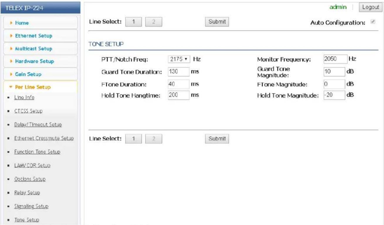
Figure 7.11: Options Setup Window - (Tone Mode)

Notice!
This Options Setup window only appears when Tone Mode is selected in the Line Type drop down menu in the Multicast Setup Window.
Cross Mute Check Box
The Cross Mute check box indicates the cross mute I/O pin (DIGO, pin 11 of the DB-37 connector) is enabled. If selected, parallel console cross mute control is enabled. Cross mute is used to mute parallel consoles during transmission.
Full Duplex Check Box
The Full Duplex check box indicates full-duplex audio is supported. If selected, full-duplex (simultaneous TX and RX transmission) audio is allowed.
Hi-Pass RX Check Box
The Hi-Pass RX check box is used to enable a 300Hz Hi-Pass filter for the RX audio.
Monitor Enable Check Box
The Monitor Enable check box indicates monitor function tone generation is allowed.
PTT Tones Decode Check Box
The PTT Tones Decode check box enables tone decoding to allow PTT frequency decoding. This allows audio from a parallel console to be sent to the network as TX packets.
PTT Tones Encode Check Box
The PTT Tones Encode check box enables tone generators. For Tone Mode this option is always on.
PTT Notch Filter Check Box
The PTT Notch Filter check box indicates the PTT notch filter is enabled. When selected, the PTT frequency is filtered from RX audio.
Supervisor Check Box
The Supervisor check box indicates the Supervisory I/O pin (DIG1, pin 30 of the DB-37 connector) is enabled. If selected, parallel console supervisory control is enabled and control of the radio can be seized from other consoles.

Figure 7.12: Options Setup Window - Console Mode

Notice!
This Options Setup window only appears when Console Mode is selected in the Line Type drop down menu in the Multicast Setup Window.
Cross Mute Check Box
The Cross Mute check box enables logic muting on PIN 11 of the I/O port, this is a input/output pin. It pulls low when a Ethernet TX is received, and sends cross mute signals to IP consoles when pulled low.
Full Duplex Check Box
The Full Duplex check box indicates full-duplex audio is supported. If selected, full-duplex (simultaneous TX and RX transmission) audio is allowed.
Hi-Pass RX Check Box
The Hi-Pass RX check box is used to enable a 300Hz Hi-Pass filter for the RX audio.
Monitor Enable Check Box
The Monitor Enable check box enables decoding of the Monitor function tone.
PTT Tones Decode Check Box
The PTT Tones Decode check box enables tone decoding to allow PTT frequency decoding. If not selected, the Console logic on Pin 32 is used to generate TX traffic for local (E&M) keying.
PTT Tones Encode Check Box
The PTT Tones Encode check box enables tone generators. This means for console systems supporting parallel updates are able to see remote channel changes.
PTT Notch Filter Check Box
The PTT Notch Filter check box enables tone notch filters based on the PTT frequency selected.
Supervisor Check Box
The Supervisor check box enables logic muting on PIN 30 of the I/O port, this is a input/output pin. It pulls low when a Ethernet SUP is received, and sends SUP signals to IP consoles when pulled low.
7.6.8 Relay Setup
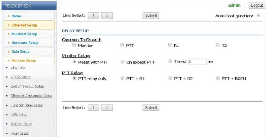
Figure 7.13: Relay Setup Window
Common to Ground Check Boxes
The Common to Ground check boxes, if selected, indicate the common connection of the Form C relay contact is connected to
ground.
Controlled relays:
- Monitor
- PTT
- R1
- R2
Monitor Relay Radio Buttons
The Monitor Relay radio buttons identify the relay operation under specified IP-224 operating conditions.
Available selections for this field are:
- Reset with PTT - The monitor relay is activated from the time the monitor command is received until the next PTT operation.
- On except PTT - The monitor relay is activated at all times except when PTT is active, whether the monitor command is received or not.
- Timed - The monitor relay is activated when the monitor command is received for the amount of time entered in the Timed ms field.
The range for this field is 0 to 32,000ms.
PTT Relay Radio Buttons
The PTT Relay radio buttons identify which relays are active with PTT.
Available selections for this field are:
- PTT relay only - Only the PTT relay is closed
- PTT+R1 - The PTT relay and relay R1 is closed
- PTT+R2 - The PTT relay and relay R2 is closed
- PTT + BOTH - The PTT relay and both relays R1 and R2 are closed
7.6.9 Signaling Setup

Figure 7.14: Signaling Setup Window
FleetSync Decode Check Box
The FleetSync Decode check box is used to enable FleetSync Over-the-Air decode. All inbound FleetSync messages are decoded by the IP-224 instead of the radio.
FleetSync Encode Check Box
The FleetSync Encode check box is used to enable FleetSync Over-the-Air encode. All outbound FleetSync messages are generated by the IP-224 instead of the radio.
MDC Decode Check Box
The MDC Decode check box is used to enable MDC-1200 Over-the-Air decode. All inbound MDC-1200 messages are decoded by the IP-224 instead of the radio.
MDC Encode Check Box
The MDC Encode check box is used to enable MDC-1200 Over-the-Air encode. All outbound MDC-1200 messages are generated by the IP-224 instead of the radio. Motorola encode features supported by the IP-224 include PTT ID, call alert, select call, radio check, remote monitor, and radio disable/enable.
MSK Tone Delay Field
The MSK Tone Delay field is used to enter the delay of MDC-1200 or FleetSync MSK signals. When Ethernet MSK signaling packets arrive, the PTT relay is closed and the MSK signal is delayed for the specified time. This provides the ability to overcome timing issues involving repeater attack times or other system delays.
The range for this field is 0 to 10,000ms.
Default is 1000ms.
MSK Tone Gain Field
The MSK Tone Gain field is used to enter the gain of MDC-1200 or FleetSync MSK signals. The range for this field is -60 to +10dB.
The default is 0 dB.
Emerg. Status 1 Field
The Emerg. Status 1 field is used to enter a status number to trigger an emergency call in IP dispatch consoles.
Emerg. Status 2 Field
The Emerg. Status 2 field is used to enter a status number to trigger an emergency call in IP dispatch consoles.
7.6.10 Tone Setup
The Tone Setup section identifies standard tone parameters. The IP-224 is capable of generating the standard tone sequences required to control a radio with a tone termination panel.

Figure 7.15: Tone Setup Window
PTT/Notch Freq Drop Down Menu
The PTT/Notch Freq drop down menu is used to select the frequency the IP-224 generates for guard/hold tones, detects for guard/hold tones, and the center frequency for the notch filter. Available selections for this field are 2100, 2175, 2300, 2325, 2400, 2600, 2800, 2850, 2970 and 3200Hz.
The default is 2175Hz.
Monitor Frequency Field
The Monitor Frequency field is used to enter the value of the function tone generated when the MON button on the console is pressed.
The range for this field is 0 to 3200Hz.
The default is 2050Hz.

Notice!
This selection appears in Tone or Console Mode.
Guard Tone Duration Field
The Guard Tone Duration field is used to enter the amount of time the IP-224 generates the guard tone and detects for the guard tone.
The range for this field is 0 to 999ms.
The default is 130ms.

Notice!
This selection appears in Tone or Console Mode.
IP-224 Configuration | en 65
| Guard Tone Magnitude FieldTheGuard Tone Magnitudefield is used to enter the level the IP-224 generates the guard tone.The range for this field is -60 to 12dB.The default is 10db. | |
 | Notice!This selection appears in Tone or Console Mode. |
| FTone Duration FieldTheFTone Durationfield is used to enter the duration the IP-224 generates the function tone and detects for the function tone. When dual function tones are set, both tones are set to this duration.The range for this field is 0 to 999ms.The default is 40ms. | |
 | Notice!This selection appears in Tone or Console Mode. |
| FTone Magnitude FieldTheFTone Magnitudefield is used to enter the level the IP-224 generates the function tone.The range for this field is -60 to 12dB.The default is 0 dB. | |
 | Notice!This selection appears in Tone or Console Mode. |
| Hold Tone Hang Time FieldTheHold Tone Hang Timefield is used to enter the amount of time the IP-224 hold tone continues after the release of the PTT button. Pressing the PTT button again during this hang time continues the transmission without sending the guard and function tones again.The range for this field is 0 to 999ms.The default is 200ms. | |
 | Notice!This selection appears in Tone or Console Mode. |
| Hold Tone Magnitude FieldTheHold Tone Magnitudefield is used to enter the level the IP-224 generates the hold tone.The range for this field is -60 to 12dB. |
The default is -20dB.

Notice!
This selection appears in Tone or Console Mode.
Submit Button
Use the Submit button to temporarily save changes to the IP-224.
To permanently save changes, do the following:
- Click the Submit button.
The changes are sent to the IP-224 in temporary storage.
- From the left navigation, select Save Parameters.
The Save Parameters window appears.
- Click the Save Parameters button.
Changes are now permanently saved to the IP-224 console.
7.7 Crosspatch Setup
The Crosspatch Setup window, shown in Figure 21, is used to view and configure the Line to Line Crosspatch feature.
Use the navigation pane on the left to open the following windows:
- Local Setup
- Network Setup

Figure 7.16: Crosspatch Setup Window
7.7.1 Local Setup
The Line to Line Crosspatch feature allows the IP-224 to re-transmit RX audio to an alternate line on the unit. When the crosspatch feature is enabled for a given line, an RX condition on the line (source) results in the TX key-up of the opposing line (destination). RX audio on the source line is duplicated and retransmitted on the destination line. The front-panel LCD shows
CPT F[x] on the destination line, where [x] is the currently selected frequency for the line.
Audio cross-patching continues until the RX condition on the source line expires, or one of the following conditions interrupts the crosspatch audio:
- Handset key-up on the destination line.
- IP TX audio traffic on destination line (TX audio from network overrides crosspatch).
Line-Line Crosspatch Drop Down Menu
There are four options for the Line-to-Line Crosspatch drop down menu.
- Disabled - Selecting this option deactivates the Line-Line Crosspatch function on the IP-224.
- Bidirectional - Selecting this option allows the IP-224 to re-transmit RX audio in both directions depending upon the incoming RX.
- Line 1 to Line 2 - Selecting this option only allows Line 2 to re-transmit RX audio from Line 1. Line 1 does not retransmit the audio from RX audio of Line 2.
- Line 2 to Line 1 - Selecting this option only allows Line 1 to re-transmit RX audio Line 2. Line 2 does not re-transmit the audio from RX audio of Line 1.
Start Patch FTone Drop Down Menu
The Start Patch FTone drop down menu is used to select the Ethernet function tone to start a crosspatch between line 1 and line 2.
The available drop down menu options are F1 to F16.
Default is None (disabled).
Stop Patch FTone Drop Down Menu
The Stop Patch FTone drop down menu is used to select the Ethernet function tone to stop a crosspatch between line 1 and line 2.
The available drop down menu options are F1 to F16.
Default is None (disabled).
IMPORTANT: When using the Start and Stop FTone, the Line-Line Crosspatch selection must not be disabled.
7.7.2 Network Setup
Ethernet Patch Timeout Field
The Ethernet Patch Timeout field is used to switch a full-duplex IP-224 line back from half-duplex when an Ethernet crosspatch is active. When the Ethernet Patch Timeout expires, the IP-224 line switches back to full-duplex regardless the Ethernet crosspatch state.
The range for this field is 0 to 3600 seconds.
Default is 0 (disabled).
Submit Button
Use the Submit button to temporarily save changes to the IP-224.
To permanently save changes, do the following:
- Click the Submit button.
The changes are sent to the IP-224 in temporary storage.
- From the left navigation, select Save Parameters.
The Save Parameters window appears.
- Click the Save Parameters button.
Changes are now permanently saved to the IP-224 console.
7.8 Account Management
The Account Management window, shown in Figure 21, is used to manage user accounts for the IP-224 web browser configuration windows, and the IP-224 system parameters may also be reset to factory default settings from this window.
Use the navigation pane on the left to open the following windows:
- System Parameters
- User Accounts

Figure 7.17: Account Management Window
7.8.1 User Accounts
Access to the IP-224 web browser configuration is protected by user names and passwords.
There is one default admin account:
Default username: admin
Default password: admin

Notice!
The admin default password should be changed to prevent unauthorized access to the IP-224. The password's length is 8-20 characters and needs to include a capital letter, a number, and a special character.
IMPORTANT:
- Only 5 user accounts can be created.
- Make note of the new password before adding or changing a password.
- The username must be unique. If the username already exists, the IP-224 displays an error and does not create the user account.
To add a user account, do the following:
- From the left navigation, select Account Management.
The Account Management window appears.
- From the User Accounts section, click the Add User button.
The Add User Account window appears.
- From the Add User Account section in the Username field, enter a username.
The username's length can be up to 20 characters.
- In the Password field, enter a password.
The password's length is 8-20 characters and needs to include a capital letter, a number, and a special character.
-
In the Confirm Password field, enter the same password assigned in the previous step.
-
From the Set User Permissions section select the check boxes to allow access to different web browser configuration windows for the user.
-
Click the Submit button.
The entries currently displayed on the window are sent to the IP-224 for storage.
- From the left navigation, select Save Parameters.
The Save Parameters window appears.
- Click the Save Parameters button.
Changes are now permanently saved to the IP-224 console.

Figure 7.18: Account Management Window - Add User Account
IMPORTANT:
- Only 5 user accounts can be created.
- Make note of the new password before adding or changing a password.
- The username must be unique. If the username already exists, the IP-224 displays an error and does not create the user account.
To edit a User Account, do the following:
- From the left navigation, select Account Management.
The Account Management window appears.
- From the User Accounts section, click the Edit button next to username to edit.
The Edit User Account window appears.
- From the Edit User Account section in the Username field, enter a new username.
The username's length can be up to 20 characters.
- In the New Password field, enter a new password.
The password's length is 8-20 characters and needs to include a capital letter, a number and a special character.

Notice!
If the password field is left blank the IP-224 will not change the password.
- In the Confirm Password field, enter the same password assigned in the previous step.
- From the Set User Permissions section select the check boxes to allow access to different web browser configuration windows for the user.
- Click the Submit button.
The entries currently displayed on the window are sent to the IP-224 for storage.
- From the left navigation, select Save Parameters.
The Save Parameters window appears.
- Click the Save Parameters button.
Changes are now permanently saved to the IP-224 console.
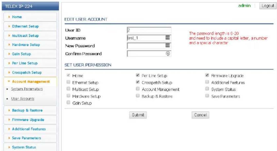
Figure 7.19: Account Management Window- Edit User Account
IMPORTANT:
- The first user account is the administrator and cannot be deleted.
- Deleting user accounts take effect immediately.
To Delete a User Account, do the following (shown in Figure 24):
- From the left navigation, select Account Management.
The Account Management window appears.
-
From the User Accounts section, select the check boxes of the user accounts that need to be deleted.
-
Click the Delete button.
The selected user accounts will be deleted.
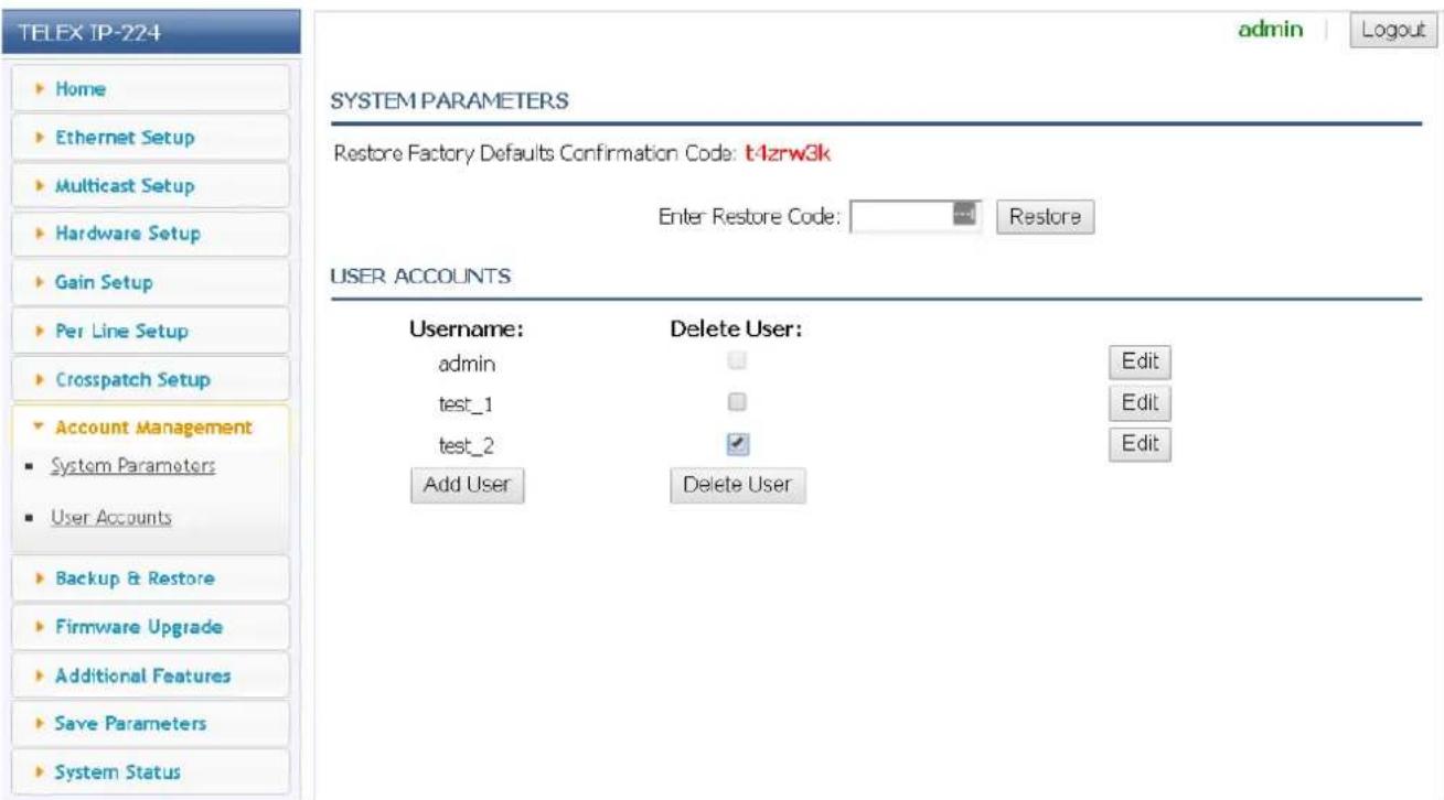
Figure 7.20: Account Management Window - Delete User Account
7.8.2 System Parameters
If required, all of the IP-224 system parameters may be reset to factory defaults. A restore code must be entered to reset the parameters. The restore code is displayed in red in the System Parameters section.
To reset the system parameters, do the following:
- In the Enter Restore Code field, enter the Restore Factory Defaults Confirmation Code.
-
Click Restore.
-
If an error occurred in the Restore Code entry, the error message shown in Figure 26 appears.
-
If the Restore code was entered correctly, the SUCCESS message shown in Figure 27 appears.
-
From the left navigation, select Save Parameters.
The Save Parameters window appears.
- Click Save Parameters.

Caution!
All user data (for example, IP Address, password, etc.) is reset back to the factory default except the additional features.

Figure 7.21: Account Management Window - Restore Code Error

Figure 7.22: Account Management Window - Restore Code Success
The Backup & Restore window is used to back up and restore the device settings of the IP-224.
Use the navigation pane on the left to open the following sections:
- Internal Storage
- External Storage

Figure 7.23: Backup & Restore Window
7.9.1 Internal Storage
Name Field
The Name field is used to enter a user-defined descriptive name (1 to 32 characters) for the backup. After the Backup is created, this name appears in the Name Column display of the Available Backups list.
Backup Button
The Backup button is used to create a backup of the current settings on the IP-224. The backup is saved to the IP-224 persistent storage.
Available Backups List
The Available Backups list displays a list of existing backups that are saved to the IP-224 persistent storage.
NOTE: The maximum number of on device backups is five. If five backups are already displayed in the Available Backups list, one must be deleted before another can be created.
Name Column Display
The Name column is used to display the Name of any existing backup files. This field is automatically populated and cannot be modified.
Time Column Display
The Time column is used to display the date and time that any existing backup files were created.
This field is automatically populated and cannot be modified.
Version Column Display
The Version column is used to display the firmware version present on the IP-224 when any existing backup files were created.
This field is automatically populated and cannot be modified.
Restore Button
The Restore button is used to restore the settings present on the IP-224 when the backup was created. A Restore button is located to the right of each existing backup.
Delete Button
The Delete button is used to delete the backup from the IP-224 persistent storage. A Delete button is located to the right of each existing backup.
To save a new backup to the IP-224 persistent storage, do the following:
- From the left navigation, select Backup & Restore.
The Backup & Restore window appears.
-
Under the Internal Storage section, enter a name for the backup in the Name field.
-
Click the Backup button.
The backup is saved to the IP-224 device storage. The backup appears in the list of Available Backups.

Notice!
The maximum number of on device backups is five. If five backups are already displayed in the Available Backups list, one must be deleted before another can be created.

To restore a backup from the IP-224 persistent storage, do the following:
- From the left navigation, select Backup & Restore.
The Backup & Restore window appears.
- In the Internal Storage section from the Available Backups list, choose the desired backup.

Notice!
Use the Name and Time fields to help identify the desired backup.
3. Click the Restore button.
The settings present at the time of the backup are restored to the IP-224.
To delete a backup from the IP-224 persistent storage, do the following:
- From the left navigation, select Backup & Restore.
The Backup & Restore window appears.
-
In the Internal Storage section from the Available Backups list, choose the desired backup.
-
Click the Delete button.
The backup is erased from the IP-224 persistent storage.
7.9.2 External Storage
Backup Button
The Backup button is used to record the current settings of the IP-224 into a file that can be saved to the local computer.
Restore Settings from a File Field
The Restore Settings from a File field is used to display the filename of the desired backup file. The filename is populated by using the Browse button.
Browse Button
The Browse button is used to find the desired backup file in the file system of the local computer. When pressed, the Browse button opens the Choose File to Upload window. This allows the user to select the .vga file containing the configuration settings to apply to the IP-224.
Restore Button
The Restore button is used to initiate the restore process after the desired backup file has been selected.
To save a new backup to the local computer, do the following:
- From the left navigation, select Backup & Restore.
The Backup & Restore window appears.
- In the External Storage section, click the Backup button.
The browser downloads a .vga file that can be viewed and edited in Telex System Manager.

- Save the file in a secure location.
To save a new backup to the local computer, do the following:
- From the left navigation, select Backup & Restore.
The Backup & Restore window appears.
- In the External Storage section, click the Browse... button.
The Choose File to Upload window appears.
-
Select the desired .vga backup file.
-
Click the Open button.
The window closes and the selected backup file is displayed in the Restore Settings from a File field.
- Click the Restore button.
The settings present at the time of the backup are restored to the IP-224
7.10 Firmware Upgrade
Use the Firmware Upgrade window to replace the firmware on the IP-224. Use the navigation pane on the left to open the following sections:
- Firmware Upgrade
- Upgrade Status

Notice!
Once the IP-224 is running version 2.8 or higher, it cannot be downgraded.

Figure 7.24: Firmware Upgrade Window
Firmware File Field
The Firmware File field displays the name of the selected firmware file.
Browse Button
The Browse button is used to select the desired firmware file from the local computer location where it is saved.
To upgrade the firmware on the IP-224, do the following:
- From the left navigation, select Firmware Upgrade.
The Firmware Upgrade window appears.
- Click the Browse button.
The Choose File to Upload window appears.
-
Select the desired .tfb file.
-
Click the Open button.
The firmware begins installing on the IP-224. The progress of the upgrade is displayed in the Upgrade Status section.
- When the upgrade completes successfully.
SUCCESS appears on the IP-224 LCD display and the IP-224 reboots.
Upgrade Status
Status Text
The Status Text displays messages describing the current status of the firmware upgrade.
Possible values are:
- Uploading file...
- Firmware upgrade successful. Rebooting...
- ERROR: Wrong device type
Progress Bar
The Progress bar displays a color coded progress bar marking the progress of the firmware upgrade.
Possible values are:
- Yellow — The upgrade is in progress.
- Green — The upgrade has successfully completed.
- Red — The upgrade process has failed. An error has occurred.

Figure 7.25: Upgrade Status: Uploading File

Figure 7.26: Upgrade Status: Successful

Figure 7.27: Upgrade Status: Error
The firmware of VoIP hardware can be updated by using TSM (Telex System Manager). The latest version of TSM is available for download from http://www.telex.com/us/dispatch/downloads.
NOTE:
- VoIP hardware includes the following Radio Dispatch devices: ADHB-4, IP-224, IP-2002, IP-1616, C-6200, and NEO-10.
- TSM uses .tfb (Telex Firmware Binary) files to update VoIP firmware.
To install TSM, do the following:
- Locate and remove earlier versions of TSM from the computer, if needed.
- Download the latest TSM from www.telex.com.

Notice!
For more information, see Firmware Upgrade, page 76.
- Unzip and double-click setup.exe.
The Telex System Manager Welcome window appears.
- Click the Next button.
The Select Installation Folder window appears.
- To specify an installation path for TSM, click the Browse button.
OR
To accept the default folder location, leave the path entered in the Folder field.
By default, TSM is installed at C:\Program Files\Telex Communications\Telex System Manager.
- Select the Everyone check box to allow any user access to TSM.
OR
Select the Just Me check box to allow the current user access to TSM.

- Click the Next button.
The Confirm Installation window appears.
- Click the Next button.
The Installing Telex System Manager appears and a Please Wait message appears. Once TSM is installed, a success message appears on the Confirm Installation window.
- Click the Close button.

Download Telex Firmware
When new firmware becomes available, it is posted to our website. It can be downloaded at http://products.telex.com/na/en/partners. Check the website periodically for updated firmware.
NOTE: Pre-approved access is required to download firmware and manuals from the web site.

Figure 7.28: Telex Website Firmware - Download Link
To download TSM, do the following:
- From the navigation pane, select Download.
The Downloads window appears.
- From the right navigation pane, select TSM.
The Telex System Manager Download window appears.
- Click the Download File icon.
The Opening TSM_Vxxx .zip window appears.
-
Select the Save File radio button.
-
Select the Do this automatically for files like this from now on check box for future downloads (optional).
-
Click the OK button.
The Enter Name of the File to Save to window appears. The filename field is populated with the TSM file name.
-
Locate a destination folder.
-
Click the Save button.
The TSM .zip file is saved to the destination folder.

Notice!
Downloading firmware is a similar process.
Update Firmware Tool Window
The Update Firmware Tool window is used to upload the newest version of firmware to the device selected in the Destination field.

Figure 7.29: Firmware Tool Window
File Field
The File field is used to select a firmware file to upload to the VoIP hardware.
Firmware File Info Group Box
Device Type Field
The Device Type field displays the type of device supported by the currently selected file in the File field.
Date Field
The Date field displays the currently selected file's firmware creation date.
Firmware Version Field
The Firmware Version field displays the currently selected file's firmware version.
Checksum Field
The Checksum field displays the currently selected file's firmware checksum
Destination Group Box
Left Navigation Pane
The Left Navigation Pane displays all detected devices from the main dialog's device list with device types that match the currently selected firmware file. Manually entered IP Addresses also appear in the navigation pane. Once the device is added, it appears in the left navigation pane and is available for selection.

Notice!
If the device you are updating does not automatically appear in the navigation pane, manually enter the IP Address in the Manual Entry field.
Manual Entry Field
The Manual Entry field is used to add the VoIP hardware's IP Address to the left navigation pane.
Login Group Box
Username Field
The Username field is used to enter the administrator's username. This field can contain up to 20 lowercase characters.

Notice!
The administrator is the only user who can update the firmware.
Password Field
The Password field is used to enter the administrator's password, if one is required. The range for this field is 8 to 20 characters.
Write Firmware Button
The Write Firmware button is used to begin the upload process. Once the button is selected, the file specified in the File field is uploaded to the VoIP hardware.
Close Button
The Close button is used to close the window.
Upload VoIP Hardware Firmware
Once TSM is installed and your new .tfb file is downloaded, you are ready to upload the VoIP hardware's firmware.
To upload the VoIP hardware's firmware, do the following:
-
Click the TSM shortcut on your desktop. OR From your taskbar, click Start | Programs | Telex Communications | Telex System Manager. The Telex System Manager window opens.
-
Click Tools | Firmware Update. The Firmware Update Tool opens.
- To locate the .tfb file for upload, click the folder icon. The Open window appears.
- Select the .tfb file you want to upload. The file is highlighted.
- Click the Open button. The selected file appears in the File field.

Notice!
If the device does not appear in the list, enter the VoIP hardware's IP Address in the Manual Entry field and click the Add icon. The IP Address appears in the left navigation pane.
-
In the left navigation, select the device's IP Address. The Write Firmware button is activated.
-
Click the Write Firmware button. Firmware update messages are shown in the Status column which provides feedback on the firmware update progress. Once the progress reaches 100%, the firmware is updated.
NOTE:
- If an error occurs, the Progress column is reset and an error message appears in the Status column. - Once the firmware is uploaded, the device resets.
- Click the Close button. The Firmware Update in Progress window closes.
- Click the Close button. The Firmware Update Tool window closes.
To access the web page directly from the Firmware Update Tool window, do the following:
- Right-click the device's entry. A Flyout menu appears.
-
From the context menu, click Webpage. The Authentication Required window opens.
-
In the Username field, enter a username.
-
In the Password field, enter a password.
-
Click the OK button. The Web Browser's Configuration Home window opens.
7.11 Additional Features Window
The Additional Features window displays the special operational software enabled and serial types available in the IP-224. Each additional feature is enabled by entering a separately purchased option code. Refer to the respective technical manuals for set up information.

Figure 7.30: Additional Features Window
These fields are automatically populated and cannot be modified.
7.12 Save Parameters
The Save Parameters window is used to save the current configuration to the IP-224. It is also used to reset the IP-224 device.

Figure 7.31: Save Parameters Window
Save Parameters Button
The Save Parameters button is used to save any changes submitted to the IP-224 for storage into permanent memory.
To save changes to permanent memory, do the following:
- From the left navigation, select Save Parameters.
The Save Parameters window appears.
- Click the Save Parameters button.
Changes are now permanently saved to the IP-224 console.

Notice!
Clicking Submit saves changes in temporary memory only. The configuration values do not take effect until Save Parameters is clicked.
Reset IP-224 Button
The Reset IP-224 button is used to perform a full reset of the IP-224. This is the software equivalent of a power down reset.
To reset the IP-224, do the following:
- From the left navigation, select Save Parameters.
The Save Parameters window appears.
- Click Reset IP-224.
The IP-224 web page displays the count down clock until the unit fully reboots. The web page home screen appears after the completion of reset.
7.13 System Status
The System Status window is used to view the IP-224's current active Ethernet port, serial connection state, and audio levels in real time, such as Handset Input, CTCSS Input, RX Input, RX IP Input, TX IP Input, and TX Monitor Input.
Use the navigation pane on the left to open the following sections:
- Ethernet Port Status
- Level Status
- Serial Connection State

Figure 7.32: System Status Window
7.13.1 Ethernet Port Status
Current Active Port Field
The Current Active Port field is used to view the IP-224's current active Ethernet port. This field is automatically populated and cannot be modified.

Notice!
The Current Active Port can also be seen in the Ethernet Setup window or via the front panel display line selection icon where an asterisk (*) indicates the Primary Ethernet port is active and a pound sign (#) indicates the Secondary Ethernet port is active.
7.13.2 Level Status
Handset Input Field
The Handset Input field displays the incoming audio level from the IP-224's handset. When no audio is received, this field will display a base value of -50dB. This field is automatically populated and cannot be modified.
Line 1 Column
The Line 1 column displays the CTSS Input, RX IP Input, RX Input, TX IP Input, and TX Monitor Input for Line 1.
Line 2 Column
The Line 2 column displays the CTSS Input, RX IP Input, RX Input, TX IP Input, and TX Monitor Input for Line 2.
CTCSS Input Field
The CTCSS Input field displays the incoming CTCSS audio level. The CTCSS input level can also be viewed via the front panel display. For more information, see "CTCSS Input Levels Menu" on page 131. When no audio is received, this field will display a base value of -50dB. This field is automatically populated and cannot be modified.
RX IP Input Field
The RX IP Input field appears when at least one line is set to Console Mode, and is used to monitor the RX Multicast audio level.
The RX IP input level can also be viewed via the front panel display. For more information, see "RX IP Input Levels Menu" on page 132. When no audio is received, this field will display a base value of -50dB.
This field is automatically populated and cannot be modified.
RX Input Field
The RX Input field displays the incoming Rx audio level. The RX input level can also be viewed via the front panel display. For more information, see "RX Input Levels Menu" on page 131. When no audio is received, this field will display a base value of -50dB.
This field is automatically populated and cannot be modified.
TX IP Input
The TX IP Input field displays the incoming TX Multicast audio level from IP dispatch consoles. The TX IP input level can also be viewed via the front panel display. For more information, see "TX IP Input Levels Menu" on page 132. When no audio is received, this field will display a base value of -50dB.
This field is automatically populated and cannot be modified.
TX Monitor Input
The TX Monitor Input field appears when at least one line is set to Tone Mode, and displays the incoming TX Monitor audio level. The TX monitor input level can also be viewed via the front panel display. For more information, see “TX Mon Input Levels Menu” on page 133. When no audio is received, this field will display a base value of -50dB.
This field is automatically populated and cannot be modified.
7.13.3 Serial Connection State
Line 1 Column
The Line 1 column displays the serial connection Type and State for Line 1.
Line 2 Column
The Line 2 column displays the serial connection Type and State for Line 2.
Type Field
The Type field displays the serial type assigned to each line. The serial type can be assigned from the Serial Type field in the Multicast Setup window. For more information, see “Line Type Drop Down Menu” on page 48 and “Serial Type Drop Down Menu” on page 49.
State Field
The State field displays the serial connection status of the line. Possible values are Connected or Not Connected.
This field is automatically populated and cannot be modified.
8 Operation
8.1 Front Panel
The IP-224 front panel uses and LCD (Liquid Crystal Display) display to provide the user with basic IP-224 information and menu options. The front panel soft keys are used to navigate through the menus and make quick changes to a few basic parameters. Front panel LEDs indicate with the IP-224 is generating IP Packets (TX) and if a network connection is established (LINK).
8.1.1 Front Panel Display
NOTE: Take care not to damage the display:
- Clean with soft cloth using ethyl alcohol or isopropyl alcohol. Do not use solvents such as ketone or aromatics.
- Do not operate or store in direct exposure to sunlight.
8.1.2 Front Panel Softkeys
The Front Panel softkeys are used to access and navigate through the programming menus.
MENU Softkey
The MENU softkey is used to access the Main menu. The MENU softkey is also used to navigate through the lower level menus and used to select menu options. Once the softkey is pressed, the Main menu appears.
IC Softkey
The IC softkey is used to return to previous menu level.
Arrow Up Softkey
The Arrow Up softkey is used to navigate the IP-224 menus by moving the selection up the menu.

Arrow Down Softkey
The Arrow Down softkey is used to navigate the IP-224 menus by moving the selection down the menu.

Positioning the arrow next to the desired selection allows the user to proceed to the next menu level by pressing the MENU softkey again.

8.2 Main Menu
The MAIN menu is used to select different system levels to control or monitor. You can also configure or display gain levels and network parameters, as well as switch on and off tones for system alignment.
Available selections for the Main Menu include:
- Systems Utilities
- Network Settings
- Input VU Meters
- Gain Adjustments


Figure 8.1: Main Menu Screen
Main Menu Structure
| MAIN MENU | |||
| SYSTEM UTILITIES | |||
| View Unit Info | |||
| Display Contrast | |||
| Remote Access | |||
| Reboot IP-224 | |||
| NETWORK SETTINGS | |||
| Auto Failover | |||
| Primary Port | |||
| DHCP | |||
| IP Address | |||
| Subnet Mask | |||
| Gateway | |||
| Ping IP Address | |||
| Ping Count | |||
| Ping Timeout | |||
| Time Btwn Pings | |||
| Secondary Port | |||
| DHCP | |||
| IP Address | |||
| Subnet Mask | |||
| Gateway | |||
| Ping IP Address | |||
| Ping Count | |||
| Ping Timeout | |||
| Time Btwn Pings | |||
| Set Active Port | |||
| INPUT VU METERS | |||
| RX Inputs | |||
| CTCSS Inputs | |||
| RX IP Inputs | |||
| TX IP Inputs | |||
| TX Monitor Inputs | |||
| Handset Mic | |||
| GAIN ADJUSTMENTS | |||
| TX Outputs | |||
| RX Inputs | |||
| TX IP Inputs | |||
| RX IP Inputs | |||
| TX Monitor Inputs | |||
| CTCSS Inputs | |||
| CTCSS Outputs | |||
| Recorder Outputs | |||
| Handsets |
8.2.1 System Utilities
The System Utilities menu is used to view unit info, display contrast, enable/disable remote access, and reboot the IP-224.

Figure 8.2: View Unit Info Menu Screen
View Unit Info Menu
The View Unit Info menu is used to display the unit's information, including network parameters, serial number, hardware version, and software version.
To display View Unit Info, do the following:
- From the home state, press the MENU softkey. The MAIN MENU appears.
- Using the arrow softkeys, select System Utilities.
- Press the MENU softkey. The SYSTEM UTILITIES menu appears.
- Using the arrow softkey, select View Unit Info.
- Press MENU softkey. The View Unit Information appears in the display.
Display Contrast Menu
The Display Contrast menu is used to set up the contrast level of the main display in front of the unit.
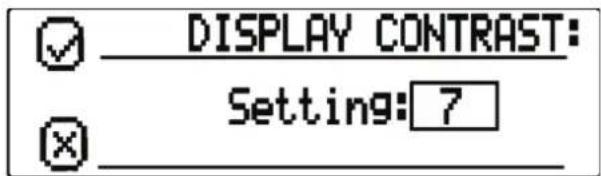
Figure 8.3: Display Contrast Menu Screen
To adjust the Contrast Level, do the following:
-
From the home state, press the MENU softkey. The MAIN MENU appears.
-
Using the arrow softkeys, select System Utilities.
-
Press the MENU softkey.
The SYSTEM UTILITIES menu appears.
-
Using the arrow softkeys, select Display Contrast.
-
Press the MENU softkey.
The DISPLAY CONTRAST menu appears.
-
Using the arrow softkeys, select the desired contrast level.
-
Press the MENU softkey to save the new contrast level.
-
Press the IC softkey to return to the previous menu.
Remote Access
The Remote Access menu is used to enable/disable Telex System Manager configuration (TSM Enable) or web browser configuration (Webpage Enable) of the IP-224.
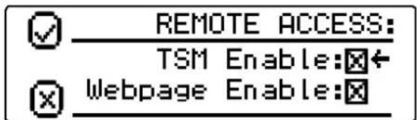
Figure 8.4: Remote Access Menu Screen
To change the remote access, do the following:
-
From the home state, press the MENU softkey. The MAIN MENU appears.
-
Using the arrow softkeys, select System Utilities.
-
Press the MENU softkey. The SYSTEM UTILITIES menu appears.
-
Using the arrow softkeys, select Remote Access.
-
Press the MENU softkey. The REMOTE ACCESS menu appears.
-
Using the arrow softkeys, select TSM Enable.
-
Press the menu softkey to enable/disable the TSM Enable check box.
-
Using the arrow softkeys, select Webpage Enable.
-
Press the MENU softkey to enable/disable the Webpage Enable check box.
-
Press the IC softkey to return to the previous menu.
Reboot IP-224 Menu
The Reboot IP-224 menu is used to reset the unit.

Figure 8.5: Reboot IP-224 Menu Screen
To reset the unit, do the following:
- From the home state, press the MENU softkey. The MAIN MENU appears.
- Using the arrow softkeys, select System Utilities.
- Press the MENU softkey. The SYSTEM UTILITIES menu appears.
- Using the arrow softkeys, select Reboot IP-224.
- Press the MENU softkey. The REBOOT IP-224 menu appears.
- Press the MENU softkey. The unit begins rebooting.
8.2.2 Network Settings
The Network Settings menu is used to view and set the IP-224's network parameters.
Available Selections include:
- Auto Failover
- Primary Port
- Secondary Port
- Set Active Port
Auto Failover Check Box
The Auto Failover Enabled check box, if selected, enables the IP-224 to ping a network IP Address with the Primary or Secondary Ethernet port. When the IP-224 boots, it sets the Primary Ethernet port as active. If the Auto Failover is enabled, the IP-224 pings the Primary Ethernet port's Ping IP Address. If the ping fails with the Primary Ethernet port, the IP-224 switches to the Secondary Ethernet port. The IP-224 continues using the Secondary Ethernet port until the ping fails on the secondary network, the port selection is changed via the web page/display, or the IP-224 is rebooted.
The Auto Failover can also be changed via the IP-224 web page configuration. This is the ping command with the fields described in the following sections:
ping -c

Notice!
Validate the Primary Port and Secondary Port Ping IP Addresses when enabling Auto Failover. If neither the Primary nor the Secondary Ping IP Address can be pinged successfully, the Active Port continuously switches between the Primary and Secondary Ethernet ports. This leads to an unreliable network connection to the IP-224.

Notice!
The current active port can be seen on the Ethernet Setup web page, System Status web page, or via the front panel display line selection icon where an asterisk (*) indicates the Primary Ethernet port is active and a pound sign (#) indicates the Secondary Ethernet port is active.

Figure 8.6: Auto Failover Check Box
To enable Auto Failover for the unit, do the following:
- From the home state, press the MENU softkey.
The MAIN MENU appears.
-
Using the arrow softkeys, select Network Settings.
-
Press the MENU softkey.
The NETWORK SETTINGS menu appears.
- Press the MENU softkey to enable the Auto Failover option check box.
An Updating message appears and the display returns to the NETWORK SETTINGS menu.
- Press the IC softkey to return to the previous menu.
Primary Port Menu
The Primary Port menu is used to enable DHCP, display or set the unit's IP Address, Subnet Mask, Gateway, Ping IP Address, Ping Count, Ping Timeout, and Time Btwn Pings for the Primary Ethernet port on the IP-224.
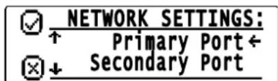
Figure 8.7: Primary Port Menu Screen
Secondary Port Menu
The Secondary Port menu is used to enable DHCP, display or set the unit's IP Address, Subnet Mask, Gateway, Ping IP Address, Ping Count, Ping Timeout, and Time Btwn Pings for the Secondary Ethernet port on the IP-224.

Figure 8.8: Secondary Port Menu Screen
DHCP Check Box
The DHCP (Dynamic Host Configuration Protocol) check box allows the IP-224 to acquire IP Addresses and other network configuration settings automatically when connected to a network.
By default DHCP check box is not selected.

Notice!
The network must allow DHCP service before the IP-224 can get the network parameters. Radio Dispatch does not recommend operating with DHCP enabled. Operating with DHCP enabled may cause the base IP Address to change unexpectedly, making changes to the software setup more difficult.

Figure 8.9: DHCP Check Box
To enable DHCP for the unit, do the following:
- From the home state, press the MENU softkey. The MAIN MENU appears.
- Using the arrow softkeys, select Network Settings.
- Press the MENU softkey. The NETWORK SETTINGS menu appears.
-
Using the arrow softkeys, select Primary Port. OR Using the arrow softkeys, select Secondary Port.
-
Press the MENU softkey. The PRIMARY PORT menu appears. OR The SECONDARY PORT menu appears.
-
Press the MENU softkey to enable the DHCP option check box. The Updating message appears and the display returns to the PRIMARY PORT or SECONDARY PORT menu.
To validate the new network setting, do the following:
- Using the arrow softkeys, select IP Address.
-
Press the MENU softkey. The IP Address of the unit appears.
-
Press the IC softkey to return to the previous menu.
Set IP Address Menu
The Set IP Address menu is used to display or set the unit's IP Address.

Figure 8.10: Set IP Address Menu Screen
To set the IP Address, do the following:
- From the home state, press the MENU softkey. The MAIN MENU appears.
-
Using the arrow softkeys, select Network Settings.
-
Press the MENU softkey.
The NETWORK SETTINGS menu appears.
- Using the arrow softkeys, select Primary Port.
OR
Using the arrow softkeys, select Secondary Port.
- Press the MENU softkey.
The PRIMARY PORT menu appears.
OR
The SECONDARY PORT menu appears.

Notice!
Verify the DHCP check box is not selected.
-
Using the arrow softkeys, select IP Address.
-
Press the MENU softkey.
The SET IP ADDRESS menu appears. The first IP Address quad is active.
-
Press the MENU softkey to change the quad field focus, as needed.
-
Press the arrow softkey to change the quad number up or down by a value of one. OR
Press and hold the arrow softkeys to rapidly change the quad number up or down.
-
Repeat steps 8 and 9 until the IP Address is complete.
-
Press the MENU softkey.
The Updating message appears and the display returns to the PRIMARY PORT or SECONDARY PORT menu.
- Press the IC softkey at any time to cancel and return to the previous menu.
Set Subnet Mask Menu
The Set Subnet Mask menu is used to display or set the unit's Subnet Mask Address. The Subnet Mask is used to distinguish local addresses from addresses requiring the use of a gateway to reach other networks. Contact your Network Administrator to obtain the proper value for this field.

SET SUBNET MASK:

255.255.0.0
Figure 8.11: Set Subnet Mask Menu Screen
To set the Subnet Mask, do the following:
- From the home state, press the MENU softkey.
The MAIN MENU appears.
-
Using the arrow softkeys, select Network Settings.
-
Press the MENU softkey.
The NETWORK SETTINGS menu appears.
- Using the arrow softkeys, select Primary Port.
OR
Using the arrow softkeys, select Secondary Port.
- Press the MENU softkey.
The PRIMARY PORT menu appears.
OR
The SECONDARY PORT menu appears.

Notice!
Verify the DHCP check box is not selected.
-
Using the arrow softkeys, select Subnet Mask.
-
Press the MENU softkey.
The SET SUBNET MASK menu appears. The first Subnet Mask quad is active.
-
Press the MENU softkey to change the quad field focus, as needed.
-
Press the arrow softkey to change the quad number up or down by a value of one.
OR
Press and hold the arrow softkeys to rapidly change the quad number up or down.
-
Repeat steps 8 and 9 until the Subnet mask settings are complete.
-
Press the MENU softkey.
The Updating message appears and the display returns to the PRIMARY PORT or SECONDARY PORT menu.
- Press the IC softkey at any time to cancel and return to the previous menu.
Set Gateway Menu
The Set Gateway menu, shown in Figure 49, is used to display or set the unit's gateway address. The gateway address is used to connect to another network.

Figure 8.12: Set Gateway Menu Screen
To set the Gateway Address, do the following:
- From the home state, press the MENU softkey.
The MAIN MENU appears.
-
Using the arrow softkeys, select Network Settings.
-
Press the MENU softkey.
The NETWORK SETTINGS menu appears.
- Using the arrow softkeys, select Primary Port.
OR
Using the arrow softkeys, select Secondary Port.
- Press the MENU softkey.
The PRIMARY PORT menu appears.
OR
The SECONDARY PORT menu appears.

Notice!
Verify the DHCP check box is not selected.
-
Using the arrow softkeys, select Gateway.
-
Press the MENU softkey.
The SET GATEWAY menu appears. The first gateway quad is active.
-
Press the MENU softkey to change the quad field focus, as needed.
-
Press the arrow softkey to change the quad number up or down by a value of one. OR
Press and hold the arrow softkeys to rapidly change the quad number up or down.
-
Repeat steps 8 and 9 until the gateway settings are complete.
-
Press the MENU softkey.
The Updating message appears and the display returns to the PRIMARY PORT or SECONDARY PORT menu.
- Press the IC softkey at any time to cancel and return to the previous menu.
Set Ping IP Address Menu
The Set Ping IP Address menu is used to display or set the Ping IP Address. The Ping IP Address is used, when Auto Failover is enabled, to set the network IP Address used in the ping command to determine if the IP-224 needs to switch Ethernet ports. If the network IP Address is unreachable, the ping command fails, and the IP-224 switches Ethernet ports.
The Ping IP Address can also be changed via the IP-224 web page configuration.

Figure 8.13: Set Ping IP Address Menu Screen
To set the Ping IP Address, do the following
-
From the home state, press the MENU softkey. The MAIN MENU appears.
-
Using the arrow softkeys, select Network Settings.
-
Press the MENU softkey. The NETWORK SETTINGS menu appears.
-
Using the arrow softkeys, select Primary Port. OR Using the arrow softkeys, select Secondary Port.
-
Press the MENU softkey. The PRIMARY PORT menu appears. OR The SECONDARY PORT menu appe
-
Using the arrow softkeys, select Ping IP Address.
-
Press the MENU softkey. The SET PING IP ADDRESS menu appears. The first Ping IP Address quad is active.
-
Press the MENU softkey to change the quad field focus, as needed.
-
Press the arrow softkey to change the quad number up or down by a value of one. OR Press and hold the arrow softkeys to rapidly change the quad number up or dow
-
Repeat steps 8 and 9 until the Ping IP Address is complete.
-
Press the MENU softkey. The Updating message appears and the display returns to the PRIMARY PORT or SECONDARY PORT menu.
-
Press the IC softkey at any time to cancel and return to the previous menu.
Set Ping Count Menu
The Set Ping Count menu is used to display or set the Ping Count. The Ping Count field is used, when Auto Failover is enabled, to set the number of ping attempts used in the ping command to determine if the IP-224 needs to switch Ethernet ports. The IP-224 attempts to ping the network IP Address the number of times configured in the Ping Count field. If the Ping IP Address is unreachable for ALL ping attempts, the ping command fails, and the IP-224 switches Ethernet ports.
The range for this field is 1 to 10.
The ping count can also be changed via the IP-224 web page configuration.

Notice!
The ping command inserts a 1 second delay between each ping attempt when the Ping IP Address is unreachable. For example, if the Ping Count is set to 5, the ping command requires a minimum of 4 seconds to complete for an unreachable Ping IP Address.
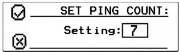
Figure 8.14: Set Ping Count Menu Screen
To set the Ping Count, do the following:
-
From the home state, press the MENU softkey. The MAIN MENU appears.
-
Using the arrow softkeys, select Network Settings.
-
Press the MENU softkey. The NETWORK SETTINGS menu appears.
-
Using the arrow softkeys, select Primary Port. OR
Using the arrow softkeys, select Secondary Port.
- Press the MENU softkey.
The PRIMARY PORT menu appears. OR
The SECONDARY PORT menu appears.
-
Using the arrow softkeys, select Ping Count.
-
Press the MENU softkey.
The SET PING COUNT menu appears.
-
Using the arrow softkeys, select the desired value.
-
Press MENU to save the new value.
The Updating message appears and the display returns to the PRIMARY PORT or SECONDARY PORT menu.
- Press the IC softkey at any time to cancel and return to the previous menu.
Set Ping Timeout Menu
The Set Ping Timeout menu is used to display or set the Ping Timeout. The Ping Timeout field is used, when Auto Failover is enabled, to set the timeout in seconds used to cancel the ping command. The timeout is started after all the Ping Count attempts have been sent. If the timer
expires and the ping command is still active, it cancels the ping command. If ALL ping attempts failed before the ping command was cancelled, then the IP-224 switches Ethernet ports.
The range for this field is 1 to 20 seconds.
The Ping Timeout can also be changed via the IP-224 web page configuration.

Notice!
There is a 1 second delay between each ping attempt. The ping command is cancelled in (Ping Count - 1) seconds plus Ping Timeout seconds when the Ping IP Address is unreachable. For example, the Ping Count is set to 5 and the Ping Timeout is set to 10, the ping command is cancelled in 14 seconds for an unreachable Ping IP Address.

Figure 8.15: Set Ping Timeout Menu Screen
To set the Ping Timeout, do the following:
- From the home state, press the MENU softkey. The MAIN MENU appears.
- Using the arrow softkeys, select Network Settings.
- Press the MENU softkey. The NETWORK SETTINGS menu appears.
- Using the arrow softkeys, select Primary Port. OR Using the arrow softkeys, select Secondary Port.
- Press the MENU softkey. The PRIMARY PORT menu appears. OR The SECONDARY PORT menu appe
- Using the arrow softkeys, select Ping Timeout.
- Press the MENU softkey. The SET PING TIMEOUT menu appears.
- Using the arrow softkeys, select the desired time.
- Press MENU to save the new time. The Updating message appears and the display returns to the PRIMARY PORT or SECONDARY PORT menu.
- Press the IC softkey at any time to cancel and return to the previous menu.
Set Time Btwn Pings Menu
The Set Time Btwn Pings menu is used to display or set the Time Between Pings. The Time Between Pings field is used, when Auto Failover is enabled, to set the amount of time in seconds between ping commands. When a ping command completes, successfully or unsuccessfully, this is the amount of time before the next ping command is executed. The range for this field is 5 to 60 seconds.
The Time Between Pings can also be changed via the IP-224 web page configuration.

Figure 8.16: Set Time Between Pings Menu Screen
To set the Time Between Pings, do the following:
- From the home state, press the MENU softkey. The MAIN MENU appears.
- Using the arrow softkeys, select Network Settings.
- Press the MENU softkey. The NETWORK SETTINGS menu appears.
-
Using the arrow softkeys, select Primary Port. OR Using the arrow softkeys, select Secondary Port.
-
Press the MENU softkey. The PRIMARY PORT menu appears. OR The SECONDARY PORT menu appears.
-
Using the arrow softkeys, select Time Btwn Pings.
-
Press the MENU softkey. The SET TIME BTWN PINGS menu appears.
-
Using the arrow softkeys, select the desired time.
-
Press MENU to save the new time. The Updating message appears and the display returns to the PRIMARY PORT or SECONDARY PORT menu.
-
Press the IC softkey at any time to cancel and return to the previous menu.
Active Port Menu
The Active Port menu is used to manually select the active Ethernet port on the IP-224. The active port can be changed regardless of the Auto Failover Enabled setting (for debug/setup purposes).
The Active Port can also be changed via the IP-224 web page configuration.
Available selections are:
Primary — Select Primary to set the PRIM Ethernet port on the IP-224 as the active port (Default).
Secondary — Select Secondary to set the SECOND Ethernet port on the IP-224 as the active port.
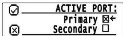
Figure 8.17: Active Port Menu Screen
To change the Active Port, do the following:
- From the home state, press the MENU softkey. The MAIN MENU appears.
- Using the arrow softkeys, select Network Settings.
-
Press the MENU softkey. The NETWORK SETTINGS menu appears.
-
Using the arrow softkeys, select the Set Active Port.
The ACTIVE PORT menu appears.
- Using the arrow softkeys, select the Secondary check box.
NOTE: By default the Primary check box is selected.

Notice!
By default, the Primary check box is selected.
- Press the MENU softkey.
The Updating message appears and the display returns to the ACTIVE PORT menu.
- Press the IC softkey to return to the previous menu.
8.2.3 Input VU Meters
The Input VU Meters menu is used to display and monitor various input audio levels. When the VU meter appears on the display and audio is being received, the total volume is represented graphically and the value is given in dB.
Available selections include:
- RX Inputs
- CTCSS Inputs
- RX IP Inputs
- TX IP Inputs
- TX Monitor Inputs
- Handset Mic
RX Input Levels Menu
The RX Input Levels menu is used to monitor the IP-224's Rx audio level.

Figure 8.18: RX Input Levels Menu Screen
To monitor the RX Inputs Levels, do the following:
- From the home state, press the MENU softkey. The MAIN MENU appears.
- Using the arrow softkeys, select Input VU Meters.
- Press the MENU softkey. The INPUT VU METERS menu appears.
- Using the arrow softkeys, select RX Inputs.
- Press the MENU softkey. The RX INPUT LEVELS menu appears. The VU meters for Line 1 and Line 2 appear.
- Press the IC softkey to return to the previous menu.
CTCSS Input Levels Menu
The CTCSS Input Levels menu is used to monitor the CTCSS audio level.
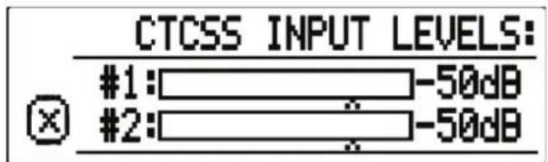
Figure 8.19: CTCSS Input Levels Menu Screen
To monitor the CTCSS Input Levels, do the following:
- From the home state, press the MENU softkey. The MAIN MENU appears.
- Using the arrow softkeys, select Input VU Meters.
- Press the MENU softkey. The INPUT VU METERS menu appears.
- Using the arrow softkeys, select CTCSS Inputs.
- Press the MENU softkey. The CTCSS INPUT LEVELS menu appears. The VU meters for Line 1 and Line 2 appear.
- Press the IC softkey to return to the previous menu.
RX IP Input Levels Menu
The RX IP Input Levels menu is used to monitor the RX Multicast audio level.

Figure 8.20: RX IP Input Levels Menu Screen
To monitor the RX IP Inputs Levels, do the following:
- From the home state, press the MENU softkey. The MAIN MENU appears.
- Using the arrow softkeys, select Input VU Meters.
- Press the MENU softkey. The INPUT VU METERS menu appears.
- Using the arrow softkeys, select RX IP Inputs.
- Press the MENU softkey. The RX IP INPUTS LEVELS menu appears. The VU meters for Line 1 and Line 2 appear.
- Press the IC softkey to return to the previous menu.
TX IP Input Levels Menu
The TX IP Input Levels menu is used to monitor the TX Multicast audio level from IP dispatch consoles.

Figure 8.21: TX IP Input Levels Menu Screen
To monitor the TX IP Input Levels, do the following:
- From the home state, press the MENU softkey. The MAIN MENU appears.
- Using the arrow softkeys, select Input VU Meters.
-
Press the MENU softkey. The INPUT VU METERS menu appears.
-
Using the arrow softkeys, select TX IP Inputs.
- Press the MENU softkey.
The TX IP INPUT LEVELS menu appears. The VU meters for Line 1 and Line 2 appear.
- Press the IC softkey to return to the previous menu.
TX Mon Input Levels Menu
The TX Mon Input Levels menu is used to monitor the TX Monitor audio level.
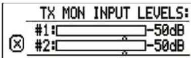
Figure 8.22: TX Mon Input Levels Menu Screen
To monitor the TX Monitor Input Levels, do the following:
- From the home state, press the MENU softkey.
The MAIN MENU appears. - Using the arrow softkeys, select Input VU Meters.
- Press the MENU softkey.
The INPUT VU METERS menu appears. - Using the arrow softkeys, select TX Monitor Inputs.
- Press the MENU softkey.
- Press the IC softkey to return to the previous menu.
The TX MON INPUT LEVELS menu appears. The VU meters for Line 1 and Line 2 appear.
Handset Mic Level Menu
The Handset Mic Level menu is used to monitor the current microphone input level from the handset.

Figure 8.23: Handset Mic Level Menu Screen
To monitor the Handset Mic Input Level, do the following:
-
From the home state, press the MENU softkey.
The MAIN MENU appears. -
Using the arrow softkeys, select Input VU Meters.
-
Press the MENU softkey.
The INPUT VU METERS menu appears.
-
Using the arrow softkeys, select Handset Mic.
-
Press the MENU softkey.
The HANDSET MIC LEVEL menu appears. The VU meter indicates the current microphone input from the handset.
- Press the IC softkey to return to the previous menu.
8.2.4 Gain Adjustment
The Gain Adjustment menu is used to view and set the IP-224's gain settings.
Available selections include:
- TX Outputs
- RX Inputs
- TX IP Inputs
- RX IP Inputs
- TX Monitor Inputs
- CTCSS Inputs
- CTCSS Outputs
- Recorder Outputs
- Handset
TX Output Gains Menu
The TX Output Gains menu is used to display or set the unit's TX Output gain settings.

Figure 8.24: TX Output Gains Menu Screen
To set the TX Output Gains, do the following:
- From the home state, press the MENU softkey.
The MAIN MENU appears. - Using the arrow softkeys, select Gain Adjustments.
- Press the MENU softkey.
The GAIN ADJUSTMENT menu appears. - Using the arrow softkeys, select TX Outputs.
-
Press the MENU softkey.
The TX OUTPUT GAINS menu appears. -
Using the arrow softkeys, scroll to the Output Gain you want to modify.
The available selections for this menu are:
Level [Line #1/2(dB)] - Adjusting the numeric value adjusts the TX Output gain for the selected line.
To adjust the gain setting, do the following:
- Using the arrow softkeys, position the indicator next to the value to be adjusted.
- Press the MENU softkey to enter gain adjustment mode.
A rectangular box appears around the gain value.
- Using the arrow softkeys, adjust the gain settings to the desired value.
Changes in gain value take effect immediately.
- Press the MENU softkey to save changes and exit the gain adjustment mode.
OR
Press the IC softkey to discard changes and exit the gain adjustment mode.
Tone - When the box is selected, the IP-224 generates an alignment tone at the TX+/- output pins.
To select/clear the Tone Enable box, do the following:
- Using the arrow softkeys, position the indicator next to the desired option.
- Press the MENU softkey to select or clear the check box.
PTT - When the box is selected, the IP-224 energizes the PTT relay for the selected line.
Alternatively, a handset plugged into the HANDSET port on the front of the unit can be used to assert PTT.
To select/clear the PTT Enable box, do the following:
- Using the arrow softkeys, position the indicator next to the desired option.
- Press the MENU softkey to select or clear the check box.
- When the gain adjustment is complete, press the IC softkey to return to the previous menu.
RX Input Gains Menu
The RX Input Gains menu is used to display or set the unit's RX Input gain settings.

Figure 8.25: RX Input Gains Menu Screen

Notice!
It is recommended to DISABLE the RX AGC (via the unit's webpage settings) while adjusting the RX Input gain.
To set the RX Input Gain, do the following:
-
From the home state, press the MENU softkey. The MAIN MENU appears.
-
Using the arrow softkeys, select Gain Adjustments.
-
Press the MENU softkey. The GAIN ADJUSTMENT menu appears.
-
Using the arrow softkeys, select RX Inputs.
-
Press the MENU softkey. The RX INPUT GAINS menu appears.
-
Using the arrow softkeys, scroll to the Input Gain you want to modify. An on-screen VU Meter displays the RX audio level for the selected line.
The available selection for this menu is:
Level [Line #1/2(dB)] - Adjusting the numeric value adjusts the RX Input gain for the selected line.
To adjust the gain setting, do the following:
- Using the arrow softkeys, position the indicator next to the value to be adjusted.
- Press the MENU softkey to enter gain adjustment mode. A rectangular box appears around the gain value.
- Using the arrow softkeys, adjust the gain settings to the desired value. Changes in gain value take effect immediately.
- Press the MENU softkey to save changes and exit the gain adjustment mode. OR
Press the IC softkey to discard changes and exit the gain adjustment mode.
- When the gain adjustment is complete, press the IC softkey to return to the previous menu.
TX IP Input Gains Menu
The TX IP Input Gains menu is used to display or set the unit's TX IP Input Gains settings.

Figure 8.26: TX IP Input Gains Menu Screen
To set the TX IP Input Gains, do the following:
- From the home state, press the MENU softkey.
The MAIN MENU appears. - Using the arrow softkeys, select Gain Adjustments.
- Press the MENU softkey.
The GAIN ADJUSTMENT menu appears. - Using the arrow softkeys, select TX IP Inputs.
-
Press the MENU softkey.
The TX IP INPUT GAINS menu appears. -
Using the arrow softkeys, scroll to the Input Gain you want to modify.
An on-screen VU Meter displays the TX IP audio level for the selected line.
The available selection for this menu are:
Level [Line #1/2(dB)] - Adjusting the numeric value adjusts the TX IP Input gain for the selected line.
To adjust the gain setting, do the following:
- Using the arrow softkeys, position the indicator next to the value to be adjusted.
- Press the MENU softkey to enter gain adjustment mode.
A rectangular box appears around the gain value.
- Using the arrow softkeys, adjust the gain settings to the desired value
Changes in gain value take effect immediately.
- Press the MENU softkey to save changes and exit the gain adjustment mode.
OR
Press the IC softkey to discard changes and exit the gain adjustment mode.
- When the gain adjustment is complete, press the IC softkey to return to the previous menu.
RX IP Input Gains Menu
The RX IP Input Gains menu is used to display or set the unit's RX IP Input Gains settings.

Figure 8.27: RX IP Input Gains Menu Screen
To set the RX IP Input Gains, do the following:
- From the home state, press the MENU softkey.
The MAIN MENU appears. - Using the arrow softkeys, select Gain Adjustments.
- Press the MENU softkey.
The GAIN ADJUSTMENT menu appears. - Using the arrow softkeys, select RX IP Inputs.
-
Press the MENU softkey.
The RX IP INPUT GAINS menu appears. -
Using the arrow softkeys, scroll to the Input Gain you want to modify.
An on-screen VU Meter displays the RX IP audio level for the selected line.
The available selection for this menu are:
Level [Line #1/2(dB)] - Adjusting the numeric value adjusts the RX IP Input gain for the selected line.
To adjust the gain setting, do the following:
- Using the arrow softkeys, position the indicator next to the value to be adjusted.
- Press the MENU softkey to enter gain adjustment mode.
A rectangular box appears around the gain value.
- Using the arrow softkeys, adjust the gain settings to the desired value.
Changes in gain value take effect immediately.
- Press the MENU softkey to save changes and exit the gain adjustment mode.
OR
Press the IC softkey to discard changes and exit the gain adjustment mode.
- When the gain adjustment is complete, press the IC softkey to return to the previous menu.
TX Mon Input Gains Menu
The TX Mon Input Gains menu is used to display or set the unit's TX Monitor Input Gains settings.

Figure 8.28: TX Monitor Input Gains Menu Screen

Notice!
It is recommended to DISABLE the RX AGC (via the unit's webpage settings) while adjusting the TX Monitor InputGains.
To set the TX Monitor Input Gains, do the following:
- From the home state, press the MENU softkey.
The MAIN MENU appears.
-
Using the arrow softkeys, select Gain Adjustments.
-
Press the MENU softkey.
The GAIN ADJUSTMENT menu appears.
-
Using the arrow softkeys, select TX Monitor Inputs.
-
Press the MENU softkey.
The TX MON INPUT GAINS menu appears.
- Using the arrow softkeys, scroll to the Input Gain you want to modify.
An on-screen VU Meter displays the TX Monitor audio level for the selected line.
The available selection for this menu is:
Level [Line #1/2(dB)] - Adjusting the numeric value adjusts the TX Monitor Input gain for the selected line.
To adjust the gain setting, do the following:
- Using the arrow softkeys, position the indicator next to the value to be adjusted.
- Press the MENU softkey to enter gain adjustment mode.
A rectangular box appears around the gain value.
- Using the arrow softkeys, adjust the gain settings to the desired value.
Changes in gain value take effect immediately.
- Press the MENU softkey to save changes and exit the gain adjustment mode.
OR
Press the IC softkey to discard changes and exit the gain adjustment mode.
- When the gain adjustment is complete, press the IC softkey to return to the previous menu
CTCSS Input Gains Menu
The CTCSS Input Gains menu is used to display or set the unit's CTCSS Input Gains settings.

Figure 8.29: CTCSS Input Gains Menu Screen
To set the CTCSS Input Gains, do the following:
-
From the home state, press the MENU softkey. The MAIN MENU appears.
-
Using the arrow softkeys, select Gain Adjustments.
-
Press the MENU softkey.
The GAIN ADJUSTMENTS menu appears.
-
Using the arrow softkeys, select CTCSS Inputs.
-
Press the MENU softkey.
The CTCSS INPUT GAINS menu appears.
- Using the arrow softkeys, scroll to the CTCSS Gain you want to modify.
An on-screen VU Meter displays the CTCSS audio level for the selected line.
The available selection for this menu is:
Level [Line #1/2(dB)] - Adjusting the numeric value adjusts the CTCSS Input gain for the selected line.
To adjust the gain setting, do the following:
- Using the arrow softkeys, position the indicator next to the value to be adjusted.
- Press the MENU softkey to enter gain adjustment mode.
A rectangular box appears around the gain value.
- Using the arrow softkeys, adjust the gain settings to the desired value.
Changes in gain value take effect immediately.
- Press the MENU softkey to save changes and exit the gain adjustment mode.
OR
Press the IC softkey to discard changes and exit the gain adjustment mode.
- When the gain adjustment is complete, press the IC softkey to return to the previous menu.
CTCSS Output Gains Menu
The CTCSS Output Gains menu is used to display or set the unit's CTCSS Output Gains settings.

Figure 8.30: CTCSS Input Gains Menu Screen
To set the CTCSS Output Gains, do the following:
- From the home state, press the MENU softkey.
The MAIN MENU appears. - Using the arrow softkeys, select Gain Adjustments.
- Press the MENU softkey.
The GAIN ADJUSTMENT menu appears. - Using the arrow softkeys, select CTCSS Outputs.
-
Press the MENU softkey.
The CTCSS OUTPUT GAINS menu appears. -
Using the arrow softkeys, scroll to the CTCSS Gain you want to modify.
The available selections for this menu are:
Level [Line #1/2(dB)] - Adjusting the numeric value adjusts the CTCSS Output gain for the selected line.
To adjust the gain setting, do the following:
- Using the arrow softkeys, position the indicator next to the value to be adjusted.
- Press the MENU softkey to enter gain adjustment mode.
A rectangular box appears around the gain value.
- Using the arrow softkeys, adjust the gain settings to the desired value.
Changes in gain value take effect immediately.
- Press the MENU softkey to save changes and exit the gain adjustment mode.
OR
Press the IC softkey to discard changes and exit the gain adjustment mode.
Enable Tone - When the box is selected, the IP-224 generates an alignment tone at the CTCSS output pin.
To select/clear the Tone Enable box, do the following:
- Using the arrow softkeys, position the indicator next to the desired option.
- Press the MENU softkey to select or clear the check box.
- When the gain adjustment is complete, press the IC softkey to return to the previous menu.
Rec Output Gains Menu
The Rec Output Gains menu is used to display or set the unit's Recorder Output Gains settings.

Figure 8.31: Recorder Output Gains Menu Screen
To set the Recorder Output Gains, do the following:
- From the home state, press the MENU softkey.
The MAIN MENU appears.
-
Using the arrow softkeys, select Gain Adjustments.
-
Press the MENU softkey.
The GAIN ADJUSTMENT menu appears.
-
Using the arrow soft keys, select Recorder Outputs.
-
Press the MENU softkey.
The REC OUTPUT GAINS menu appears.
- Using the arrow softkeys, scroll to the Recorder Gain you want to modify.
The available selections for this menu are:
Level [Line #1/2(dB)] - Adjusting the numeric value adjusts the Recorder Output gain for the selected line.
To adjust the gain setting, do the following:
- Using the arrow softkeys, position the indicator next to the value to be adjusted.
- Press the MENU softkey to enter gain adjustment mode.
A rectangular box appears around the gain value.
- Using the arrow softkeys, adjust the gain settings to the desired value.
Changes in gain value take effect immediately.
- Press the MENU softkey to save changes and exit the gain adjustment mode.
OR
Press the IC softkey to discard changes and exit the gain adjustment mode.
Enable Tone - When the box is selected, the IP-224 generates an alignment tone at the RECORDER +/- output pins.
To select/clear the Tone Enable box, do the following:
- Using the arrow softkeys, position the indicator next to the desired option.
- Press the MENU softkey to select or clear the check box.
- When the gain adjustment is complete, press the IC softkey to return to the previous menu.
Handset Gains Menu
The Handset Gains menu is used to configure the unit's Handset Gains settings.

Figure 8.32: Handset Gains Menu Screen
To set the Handset Gains, do the following:
-
From the home state, press the MENU softkey. The MAIN MENU appears.
-
Using the arrow softkeys, select Gain Adjustments.
-
Press the MENU softkey. The GAIN ADJUSTMENT menu appears.
-
Using the arrow softkeys, select Handset.
-
Press the MENU softkey. The HANDSET GAINS menu appears.
-
Using the arrow softkeys, scroll to the Handset Gains menu option desired.
The available selections for this menu are:
Mic Gain (dB) - Adjusting the numeric value adjusts the Handset Mic gain. An on-screen VU meter displays the Handset Mic input audio level.
To adjust the gain setting, do the following:
- Using the arrow softkeys, position the indicator next to the value to be adjusted.
- Press the MENU softkey to enter gain adjustment mode.
A rectangular box appears around the gain value.
- Using the arrow softkeys, adjust the gain settings to the desired value.
Changes in gain value takes effect immediately.
- Press the MENU softkey to save changes and exit the gain adjustment mode. OR
Press the IC softkey to discard changes and exit the gain adjustment mode.
Output Level [Line #1/2(dB)] - Adjusting the numeric value adjusts the Handset Output audio level for the selected line.
To adjust the gain setting, do the following:
- Using the arrow softkeys, position the indicator next to the value to be adjusted.
- Press the MENU softkey to enter gain adjustment mode.
A rectangular box appears around the gain value.
- Using the arrow softkeys, adjust the gain settings to the desired value.
Changes in gain value take effect immediately.
- Press the MENU softkey to save changes and exit the gain adjustment mode. OR
Press the IC softkey to discard changes and exit the gain adjustment mode.
Sidetone Gain- Adjusting the numeric value adjusts the Handset Sidetone audio level for the selected line.
To adjust the gain setting, do the following:
- Using the arrow softkeys, position the indicator next to the value to be adjusted.
- Press the MENU softkey to enter gain adjustment mode.
A rectangular box appears around the gain value.
- Using the arrow softkeys, adjust the gain settings to the desired value.
Changes in gain value take effect immediately.
- Press the MENU softkey to save changes and exit the gain adjustment mode. OR
Press the IC softkey to discard changes and exit the gain adjustment mode.
- When the gain adjustment is complete, press the IC softkey to return to the previous menu.
8.3 Factory Mode
Factory Mode is used to reset the web browser configuration user accounts and to reset all of the unit's parameters to factory defaults.
Factory Mode Screen
The Factory Mode screen is used to select Reset Accounts or Factory Defaults.

Figure 8.33: Factory Mode Menu Screen

Notice!
Once the menu is accessed, a left arrow appears in the display next to the currently selected menu option.
Reset Accounts Check Box
The Reset Accounts check box allows the operator to reset the web browser configuration user accounts on the IP-224. Once selected, the default username and the default password of the unit are reset to admin.
To reset the user accounts, do the following:
- Turn the unit on.
- From the home state, press the MENU softkey. The MAIN MENU appears.
- Using the arrow softkeys, scroll to System Utilities.
- Press the Menu softkey. The SYSTEM UTILITIES menu appears.
- Using the arrow softkeys, scroll to View Unit Info.
- Press the Menu softkey. The View Unit Info screen appears.
- While the View Unit Info screen is displayed, use the Arrow Up and Arrow Down buttons to perform the following sequence: up, up, down, and down. The FACTORY MODE menu appears.
- Using the arrow softkeys, select Reset Accounts.
- Press the Menu softkey. The Accounts are Reset.
Factory Defaults Check Box
The Factory Defaults check box allows the operator to reset all the unit's parameters to default.
To reset the IP-224 back to the factory defaults, do the following:
- Turn the unit on.
- From the home state, press the MENU softkey. The MAIN MENU appears.
- Using the arrow softkeys, scroll to System Utilities.
- Press the Menu softkey. The SYSTEM UTILITIES menu appears.
- Using the arrow softkeys, scroll to View Unit Info.
-
Press the Menu softkey. The View Unit Info screen appears.
-
While the View Unit Info screen is displayed, use the Arrow Up and Arrow Down softkeys to perform the following sequence: up, up, down, and down. The FACTORY MODE menu appears.
-
Using the arrow softkeys, select Factory Defaults.
-
Press the Menu softkey. Parameters are Reset and Rebooting appears.
8.4 Console Mode
Console Mode allows an analog tone console to be configured as a networked IP console resource. The IP-224 implements console mode to encode/decode industry standard tones allowing an analog tone console to control and monitor radio traffic via an IP network.
Features
- 2/4 Wire Tone Operations
- 6-Wire E&M Audio and Logic Operation
- RX and TX Audio, Simplex or Full-Duplex
- PTT and Monitor Decode
- Up to 16 Channel Changes
- Parallel Console Cross-Muting and Supervisor Function
- Parallel Console Updating from Remote Console Changes
8.4.1 System Operation
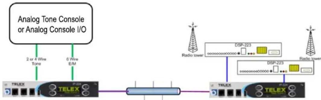
flowchart
graph LR
    A["TELEX"] -->|2 or 4 Wire Tone| B["TeLEX"]
    B -->|6 Wire E/M| C["Power Supply"]
    C --> D["TeLEX"]
    D --> E["DSP-223"]
    E --> F["Radio tower"]
    E --> G["DSP-223"]
    G --> H["Radio tower"]
IP-224 in Console mode
IP-224 in Tone mode
Console PTT
PTT tones and microphone audio generated by the analog console are decoded by the attached IP-224 operating in Console Mode, and CTX Fx (x = Frequency) will be shown on the unit's display. In addition to 2/4 wire tone operation, the IP-224 can support 6-wire E/M (Local) analog console input, controlling a single frequency.
The PTT tones are notched (removed) and the microphone audio is sampled and VOCODED for IP transport. TX packets are created with the decoded frequency tone in the packet header, and the voice payloads are transmitted to the network for transport to the radio end IP-224 in Local or Tone Modes.
The radio end IP-224 will receive and decode the network packets, regenerate the PTT tones, and insert the audio created at the analog console end IP-224 to the connected tone remote or radio.
Radio Receive
The radio end IP-224 receives RX audio from the attached radio. RX Fx (x = Frequency) will be shown on unit display and RX packets are generated to the network.
The analog console end IP-224 will receive and decode network packets. CRX Fx (x = Frequency) will be shown on unit display and RX audio is regenerated to the attached analog console.
8.4.2 Hardware Installation
2 and 4 Wire Tone

6 Wire E&M

flowchart
graph LR
    A["Analog Console I/O"] -->|TX Audio| B["Pins 20 & 21"]
    A -->|PTT Closure| C["Pin 32"]
    A -->|Ground| D["Pin 29"]
    A -->|RX Audio| E["Pins 1 & 2"]
Optional Connections

flowchart
graph LR
    A["Analog Tone Console or Analog Console I/O"] <-->|X-Mute| B["Pin 11"]
    A <-->|Supervisor| C["Pin 30"]

Notice!
The analog console may not support connections for hard-wired Crossmute and Supervisor functions between analog console and IP-224 (shown above).
8.4.3 Configuration
To configure Console Mode, do the following:
- From the left navigation, select Multicast Setup.
The Multicast Setup window appears.

Under Line Setup
- From the Line Type drop down menu, select Console Mode.
- In the RX Mcast field, enter the Receive Multicast IP Address.
- In the RX Port field, enter the Receive Multicast Port number.
- In the TX Mcast field, enter the Transmit Multicast IP Address.
- In the TX Port field, enter the Transmit Multicast Port number.
- Click the Submit button.
The changes are sent to the IP-224 temporary storage. - From the left navigation, select Hardware Setup.
The Hardware Setup window appears.
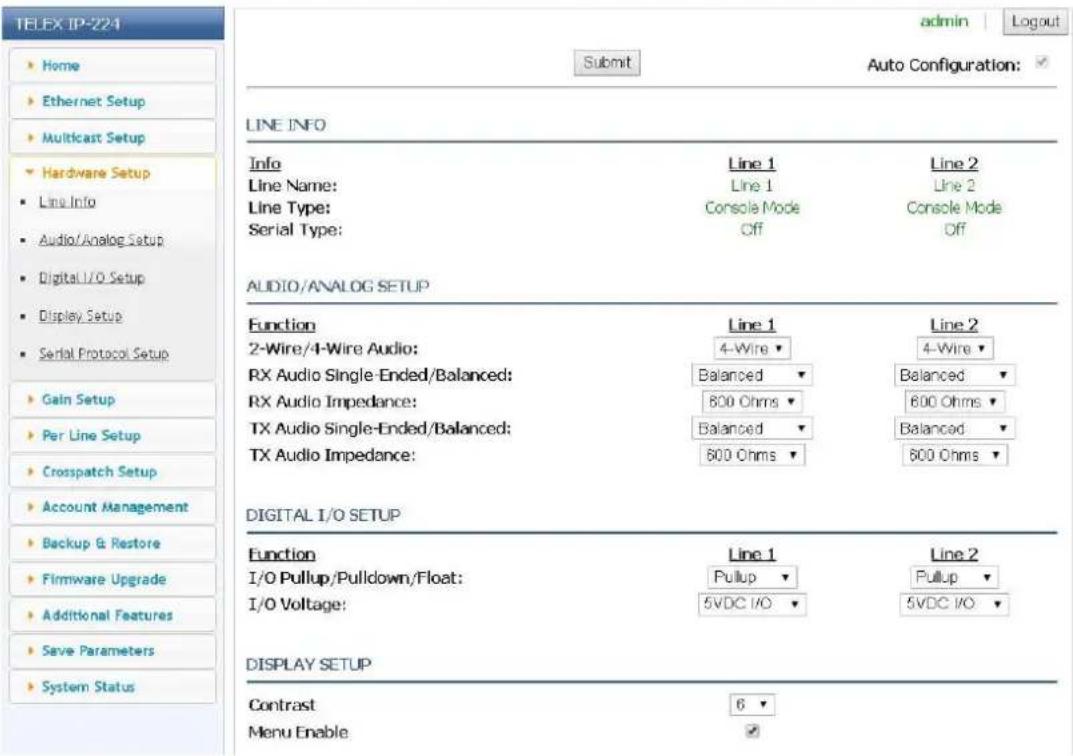
Under Audio/Analog Setup
- From the 2-Wire/4-Wire Audio drop down menu, select 2-Wire or 4-Wire, depending on analog console connections.
- Click the Submit button.
The changes are sent to the IP-224 temporary storage.
- From the left navigation, select Per Line Parameters.
The Per Line Parameters window appears.
Under Ethernet Crossmute Setup
- In the text fields, enter the IP Addresses of IP consoles located in the same room.

Under Function Tone Setup
- Select the Enable check box for each frequency you want the Console Mode IP-224 to encode.
NOTE: Tone Freq 1 and Freq 2 columns are for tone encoding only and have no effect on tone decoding.

Under LAM Setup
- Select the LAM Enable check box.
NOTE: Audio decode levels are based on LAM level; adjustments may be required based on system audio levels.
LAM SETUP

Under Optional Setup
- Select the desired check boxes.
NOTE: Optional setup determines operational characteristics that may be needed by the analog console.
OPTIONS SETUP
Cross Mute
Full Duplex
Hi-Pass RX
Monitor Enable
PTT Tones Decode
PTT Tones Encode
PTT Notch Filter
Supervisor
Cross Mute Check Box
The Cross Mute check box enables logic muting on PIN 11 of the I/O port; this is an input/output pin. It pulls low when an Ethernet TX is received, and sends cross mute signals to IP consoles when pulled low.
Full Duplex Check Box
The Full Duplex check box indicates full-duplex audio is supported. If selected, full-duplex (simultaneous TX and RX transmission) audio is allowed.
Hi-Pass RX Check Box
The Hi-Pass RX check box is used to enable a 300Hz Hi-Pass filter for the RX audio.
Monitor Enable Check Box
The Monitor Enable check box enables decoding of the Monitor function tone.
PTT Tones Decode Check Box
The PTT Tones Decode check box enables tone decoding to allow PTT frequency decoding. If not selected, the Console logic on Pin 32 is used to generate TX traffic for local (E&M) keying.
PTT Tones Encode Check Box
The PTT Tones Encode check box enables tone generators. This means for console systems supporting parallel updates are able to see remote channel changes.
PTT Notch Filter Check Box
The PTT Notch Filter check box enables tone notch filters based on the PTT frequency selected.
Supervisor Check Box
The Supervisor check box enables logic muting on PIN 30 of the I/O port; this is an input/output pin. It pulls low when an Ethernet SUP is received, and sends SUP signals to IP consoles when pulled low.
Under Tone Setup
TONE SETUP
| PTT/Notch Freq: | 2175 | Hz | Monitor Frequency: | 2050 | Hz |
| Guard Tone Duration: | 130 | ms | Guard Tone Magnitude: | 10 | dB |
| FTone Duration: | 40 | ms | FTone Magnitude: | 0 | dB |
| Hold Tone Hangtime: | 200 | ms | Hold Tone Magnitude: | -20 | dB |
Line Select:

Submit
- From the PTT/Notch Freq drop down menu, select the decode/encode frequency.
- Click Submit.
The changes are sent to the IP-224 temporary storage.
- From the left navigation, select Save Parameters.
The Save Parameters window appears.
- Click the Save Parameters button.
Changes are permanently saved to the IP-224 console.
9 Maintenance
9.1 IP-224 Main Board Service
The IP-224 mainboard can be replaced while the unit remains connected to radios, Ethernet, and power.
To replace the IP-224's mainboard, do the following:
- Remove the two screws (A) on the front of the unit.
- Thread the supplied thumbscrews into front panel.
- Pull the board display assembly (B) completely out of the unit. The board unplugs and the display is blank.
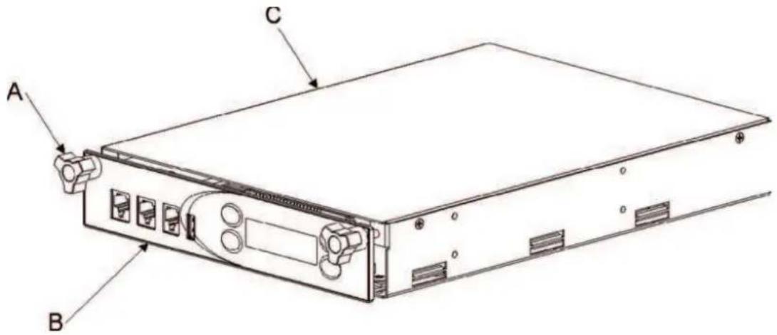
- Using the six board guides (C) inside the IP-224, carefully slide the replacement board into the unit, ensuring the board is located inside the board guides (C).
- Push the board completely into the unit (B) until it is seated in the connector (not shown) at the back of the unit.
The board is connected and the display is active.
- Using the two screws (removed in step 1), attach the board display assembly (A) to the IP-224 chassis (B).


Notice!
Thumbscrews are not used to install the PCB into the chassis.
10 Technical data
| Power Requirements +11 VDC to +16 VDC, 600 | mA nominal |
| Ethernet Speed 10 BASE-T or 100 BASE-TX | |
| Flash Memory 128 MB | |
| SDRAM Memory 256 MB | |
| Electro-Static Discharge Immunity 8 kV on all exposed operator control areas. At 8 kV no permanent damage | |
| Lease Line 2-Wire and 4-Wire supported | |
| Radio Interface ±45 VDC withstand rating | |
| Hum and Noise 60 dB below rated output for each line | |
| Non-Relay Outputs Open collector, active low, 200 mA maximum, 40 VDC collector to emitter voltage | |
| Radio Input Level 10 mVp-p to 10 Vp-p, adjustable | |
| Line Output Level 10 mVp-p to 10 Vp-p, adjustable (Single-Ended) 20 mVp-p to 40 Vp-p, adjustable (Balanced) | |
| Tone Frequencies Single or dual function tone generation Function tone range 0 Hz to 3200 Hz adjustable in 1 Hz increments Total tone duration 0 ms to 999 ms Tone magnitude -60 dB to +12 dB | |
| Vocoder Telex 32K (50 kbits/sec simplex, G.726 16K (34 kbits/sec simplex), G.726 32K (50 kbits/sec simplex), G.711 (82 kbits/sec simplex) | |
| Relay Contact Ratings | 1A at 63 V AC/DC |
| Digital I/O Ratings | Pull up/pull down/float 3.3 VDC/5 VDC/12 VDC 10K Ohm pull up/pull down |
| Transmit Output Impedance | 600 Ohms for balanced mode, 200 Ohms for single-ended mode |
| Receive Input Impedance | 10/600/K Ohms (User-selectable) |
| Audio Distortion | 2% THD maximum |
| Audio Frequency Response | 300 Hz to 3000 Hz +1, -3 dB less than 3% distortion |
| LAM Sensitivity | -50 dB to +10 dB |
| COR Sensitivity | User selectable rising or falling edge from radio |
| DTMF Detection Bandwidth | ±25 Hz around center of frequency |
| Monitor Timer | 10 ms to 9999 ms, adjustable |
| Control Type 32-bit Digital Media Processor | |
| Line Protection Fast-acting solid state surge protection | |
| Memory Protection Settings preserved in non-volatile memory | |
| Level Controls Menu driven front panel controls for TX, RX, spare audio and CTCSS | |
| Operating Temperature 32^ F to 122^ F ( 0^ C to 50^ C) for full specifications | |
| Storage Temperature -22^ F to 149^ F (- 30^ C to 65^ C) for full specifications | |
| Dimensions 1.625 in. H, 8.5 in W x 11.5 in D | (41.3 mm H x 215.9 mm W x 292.1 mm D) |
| Actual Weight 4.125 lbs (1.9 kg) | |
| Shipping Weight and Dimensions 7 lbs (5 in H x 16 in W x 15 in D)3.2 kg (127 mm H x 406 mm W x 381 mm D) | |

Notice!
Specifications are subject to change without notice.
11 Appendix A - CTCSS Tone Frequency Table
| Tone Number Freq. (Hz) | |
| 1 33.0 | |
| 2 35.4 | |
| 3 36.6 | |
| 4 37.9 | |
| 5 39.6 | |
| 6 44.4 | |
| 7 47.5 | |
| 8 49.2 | |
| 9 51.2 | |
| 10 53.0 | |
| 11 54.9 | |
| 12 56.8 | |
| 13 58.8 | |
| 14 63.0 | |
| 15 67.0 | |
| 16 69.4 | |
| 17 71.9 | |
| 18 74.4 | |
| 19 77.0 | |
| 20 79.7 | |
| 21 82.5 | |
| 22 85.1 | |
| 23 88.5 | |
| 24 91.5 | |
| 25 94.8 | |
| 26 97.4 | |
| 27 100.0 | |
| 28 103.5 | |
| 29 107.2 | |
| 30 110.9 | |
| 31 114.8 | |
| 32 118.8 | |
| 33 123.0 | |
| 34 127.3 | |
| 35 131.8 | |
| 36 136.5 | |
| 37 141.3 | |
| 38 146.2 | |
| 39 151.4 | |
| 40 156.7 | |
| 41 159.8 | |
| 42 162.2 | |
| 43 165.5 | |
| 44 167.9 | |
| 45 171.3 | |
| 46 173.8 | |
| 47 177.3 | |
| 48 179.9 | |
| 49 183.5 | |
| 50 186.2 | |
| 51 189.9 | |
| 52 192.8 | |
| 53 196.6 | |
| 54 199.5 | |
| 55 203.5 | |
| 56 206.5 | |
| 57 210.7 | |
| 58 218.1 | |
| 59 225.7 | |
| 60 229.1 | |
| 61 233.6 | |
| 62 241.8 | |
| 63 250.3 | |
| 64 254.1 |
Table 11.9: CTCSS Tone Frequencies
12 Appendix B - Digital Output Table
| Value DIG7 | DIG6 | DIG5 | DIG4 | DIG3 | DIG2 | DIG1 | DIG0 | ||||
| 0 | LLLL | LLLL | |||||||||
| 1 | LLLL | LLLH | |||||||||
| 2 | LLLL | LHL | |||||||||
| 3 | LLLL | LHH | |||||||||
| 4 | LLLL | HLL | |||||||||
| 5 | LLLL | HLH | |||||||||
| 6 | LLLL | HHL | |||||||||
| 7 | LLLL | HHH | |||||||||
| 8 | LLLL | HLLL | |||||||||
| 9 | LLLL | HLLH | |||||||||
| 10 | LLLL | HLHL | |||||||||
| 11 | LLLL | HLHH | |||||||||
| 12 | LLLL | HHLL | |||||||||
| 13 | LLLL | HHLH | |||||||||
| 14 | LLLL | HHHL | |||||||||
| 15 | LLLL | HHHH | |||||||||
| 16 | LLLL | LLLL | |||||||||
| 17 | LLLL | LLLH | |||||||||
| 18 | LLLL | LLHL | |||||||||
| 19 | LLLL | LLHH | |||||||||
| 20 | LLLL | LHLL | |||||||||
| 21 | LLLL | LHLH | |||||||||
| 22 | LLLL | LHHL | |||||||||
| 23 | LLLL | LHHH | |||||||||
| 24 | LLLL | HLLL | |||||||||
| 25 | LLLL | HLLH | |||||||||
| 26 | LLLL | HLHL | |||||||||
| 27 | LLLL | HLHH | |||||||||
| 28 | LLLL | HHLL | |||||||||
| 29 | LLLL | HHLH | |||||||||
| 30 | LLLL | HHHL | |||||||||
| 31 | LLLL | HHHH |
| Value DIG7 DIG6 DIG5 DIG4 DIG3 DIG2 DIG1 DIG0 | |||||||
| 32 L L H L | L L L L | ||||||
| 33 L L H L | L L L H | ||||||
| 34 L L H L | L L H L | ||||||
| 35 L L H L | L L H H | ||||||
| 36 L L H L | L H L L | ||||||
| 37 L L H L | L H L H | ||||||
| 38 L L H L | L H H L | ||||||
| 39 L L H L | L H H H | ||||||
| 40 L L H L | H L L L | ||||||
| 41 L L H L | H L L H | ||||||
| 42 L L H L | H L H L | ||||||
| 43 L L H L | H L H H | ||||||
| 44 L L H L | H H L L | ||||||
| 45 L L H L | H H L H | ||||||
| 46 L L H L | H H H L | ||||||
| 47 L L H L | H H H H | ||||||
| 48 L L H H | H L L L | ||||||
| 49 L L H H | H L L H | ||||||
| 50 L L H H | H L L H | ||||||
| 51 L L H H | H L H H | ||||||
| 52 L L H H | H L H L | ||||||
| 53 L L H H | H L H L H | ||||||
| 54 L L H H | H L H H | ||||||
| 55 L L H H | H L H H | ||||||
| 56 L L H H | H L L L | ||||||
| 57 L L H H | H L L H | ||||||
| 58 L L H H | H L H L | ||||||
| 59 L L H H | H L H H | ||||||
| 60 L L H H | H H H L | ||||||
| 61 L L H H | H H H L H | ||||||
| 62 L L H H | H H H H L | ||||||
| 63 L H H H | H H H H H | ||||||
| 64 L H H L | L L L L | ||||||
| 65 L H L L L L L H | |||||||
| 66 L H L L L L H L | |||||||
| 67 L H L L L L H H | |||||||
| 68 L H L L L H L L | |||||||
| 69 L H L L L H L H | |||||||
| 70 L H L L L H H L | |||||||
| 71 L H L L L H H H | |||||||
| 72 L H L L L H L L | |||||||
| 73 L H L L L H L L H | |||||||
| 74 L H L L L H L H L | |||||||
| 75 L H L L L H L H H | |||||||
| 76 L H L L L H H L L | |||||||
| 77 L H L L L H H L H | |||||||
| 78 L H L L L H H H L | |||||||
| 79 L H L L L H H H H | |||||||
| 80 L H L H L L L L | |||||||
| 81 L H L H L L L H | |||||||
| 82 L H L H L L H L | |||||||
| 83 L H L H L L H H | |||||||
| 84 L H L H L H L L | |||||||
| 85 L H L H L H L H | |||||||
| 86 L H L H L H H L | |||||||
| 87 L H L H L H H H | |||||||
| 88 L H L H H H L L | |||||||
| 89 L H L H H H L L H | |||||||
| 90 L H L H H H L H | |||||||
| 91 L H L H H H L H H | |||||||
| 92 L H L H H H H L L | |||||||
| 93 L H L H H H H L H | |||||||
| 94 L H L H H H H H L | |||||||
| 95 L H L H H H H H H | |||||||
| 96 L H H H L L L L L | |||||||
| 97 L H H H L L L L H | |||||||
| Value DIG | 7 DIG6 DIG | 5 DIG4 | DIG3 DIG2 | DIG1 DIG0 | |||
| 98 L H H L | L L H L | ||||||
| 99 L H H L | L L H H | ||||||
| 100 L H H | L L H L L | ||||||
| 101 L H H | L L H L H | ||||||
| 102 L H H | L L H H L | ||||||
| 103 L H H | L L H H H | ||||||
| 104 L H H | L H L L L | ||||||
| 105 L H H | L H L L H | ||||||
| 106 L H H | L H L H L | ||||||
| 107 L H H | L H L H H | ||||||
| 108 L H H | L H H L L | ||||||
| 109 L H H | L H H L H | ||||||
| 110 L H H | L H H H L | ||||||
| 111 L H H | L H H H H | ||||||
| 112 L H H | H L L L L | ||||||
| 113 L H H | H L L L H | ||||||
| 114 L H H | H L L H L | ||||||
| 115 L H H | H L L H H | ||||||
| 116 L H H | H L H L L | ||||||
| 117 L H H | H L H L H | ||||||
| 118 L H H | H L H H L | ||||||
| 119 L H H | H L H H H | ||||||
| 120 L H H | H H L L L | ||||||
| 121 L H H | H H L L H | ||||||
| 122 L H H | H H L H L | ||||||
| 123 L H H | H H L H H | ||||||
| 124 L H H | H H H L L | ||||||
| 125 L H H | H H H L H | ||||||
| 126 L H H | H H H H L | ||||||
| 127 L H H | H H H H H | ||||||
| 128 H L L | L L L L L | ||||||
| 129 H L L | L L L L H | ||||||
| 130 H L L | L L L H L | ||||||
| Value DIG | 7 DIG6 DIG5 DIG4 DIG3 DIG2 DIG1 DIG0 | ||||||
| 131 HLL | LLLHH | ||||||
| 132 HLL | LLHLL | ||||||
| 133 HLL | LLHHL | ||||||
| 134 HLL | LLHHL | ||||||
| 135 HLL | LLHHH | ||||||
| 136 HLL | LHLLL | ||||||
| 137 HLL | LHLLH | ||||||
| 138 HLL | LHLHL | ||||||
| 139 HLL | LHLHH | ||||||
| 140 HLL | LHHLL | ||||||
| 141 HLL | LHHLH | ||||||
| 142 HLL | LHHHL | ||||||
| 143 HLL | LHHHH | ||||||
| 144 HLL | HLLLL | ||||||
| 145 HLL | HLLLH | ||||||
| 146 HLL | HLLHL | ||||||
| 147 HLL | HLLHH | ||||||
| 148 HLL | HLHLL | ||||||
| 149 HLL | HLHLH | ||||||
| 150 HLL | HLHHL | ||||||
| 151 HLL | HLHHH | ||||||
| 152 HLL | HLLLL | ||||||
| 153 HLL | HHLHL | ||||||
| 154 HLL | HHLHL | ||||||
| 155 HLL | HHLHH | ||||||
| 156 HLL | HHHLL | ||||||
| 157 HLL | HHHLH | ||||||
| 158 HLL | HHHHL | ||||||
| 159 HLL | HHHHH | ||||||
| 160 HLL | LLLLL | ||||||
| 161 HLL | LLLLH | ||||||
| 162 HLL | LLLHL | ||||||
| 163 HLL | LLLHH | ||||||
| Value DIG | 7 DIG6 DIG | 5 DIG4 | DIG3 DIG2 | DIG1 DIG0 | |||
| 164 H L H | L L H L L | ||||||
| 165 H L H | L L H L H | ||||||
| 166 H L H | L L H H L | ||||||
| 167 H L H | L L H H H | ||||||
| 168 H L H | L H L L L | ||||||
| 169 H L H | L H L L H | ||||||
| 170 H L H | L H L H L | ||||||
| 171 H L H | L H L H H | ||||||
| 172 H L H | L H H H L | ||||||
| 173 H L H | L H H L H | ||||||
| 174 H L H | L H H H L | ||||||
| 175 H L H | L H H H H | ||||||
| 176 H L H | H L L L L | ||||||
| 177 H L H | H L L L H | ||||||
| 178 H L H | H L L H L | ||||||
| 179 H L H | H L L H H | ||||||
| 180 H L H | H L H H L | ||||||
| 181 H L H | H L H H L | ||||||
| 182 H L H | H L H H L | ||||||
| 183 H L H | H L H H H | ||||||
| 184 H L H | H H L L L | ||||||
| 185 H L H | H H L H L | ||||||
| 186 H L H | H H L H L | ||||||
| 187 H L H | H H L H H | ||||||
| 188 H L H | H H H H L | ||||||
| 189 H L H | H H H H L H | ||||||
| 190 H L H | H H H H H L | ||||||
| 191 H L H | H H H H H H | ||||||
| 192 H H L | L L L L L | ||||||
| 193 H H L | L L L L H | ||||||
| 194 H H L | L L L H L | ||||||
| 195 H H L | L L L H H | ||||||
| 196 H H L | L L H L L | ||||||
| Value DIG | 7 DIG6 DIG5 DIG4 DIG3 DIG2 DIG1 DIG0 | ||||||
| 197 H H L | L L H L H | ||||||
| 198 H H L | L L H H L | ||||||
| 199 H H L | L L H H H | ||||||
| 200 H H L | L H L L L | ||||||
| 201 H H L | L H L L H | ||||||
| 202 H H L | L H L H L | ||||||
| 203 H H L | L H L H H | ||||||
| 204 H H L | L H H L L | ||||||
| 205 H H L | L H H L H | ||||||
| 206 H H L | L H H H L | ||||||
| 207 H H L | L H H H H | ||||||
| 208 H H L | H L L L L | ||||||
| 209 H H L | H L L L H | ||||||
| 210 H H L | H L L H L | ||||||
| 211 H H L | H L L H H | ||||||
| 212 H H L | H L H L L | ||||||
| 213 H H L | H L H L H | ||||||
| 214 H H L | H L H H L | ||||||
| 215 H H L | H L H H H | ||||||
| 216 H H L | H H L L L | ||||||
| 217 H H L | H H L L H | ||||||
| 218 H H L | H H L H L | ||||||
| 219 H H L | H H L H H | ||||||
| 220 H H L | H H H L L | ||||||
| 221 H H L | H H H L H | ||||||
| 222 H H L | H H H H L | ||||||
| 223 H H L | H H H H H | ||||||
| 224 H H H | L L L L L | ||||||
| 225 H H H | L L L L H | ||||||
| 226 H H H | L L L H L | ||||||
| 227 H H H | L L L H H | ||||||
| 228 H H H | L L H L L | ||||||
| 229 H H H | L L H L H | ||||||
| Value DIG | 7 DIG6 DIG | 5 DIG4 DIG | 3 DIG2 DIG1 DIG0 | ||||
| 230 H H H | L L H H L | ||||||
| 231 H H H | L L H H H | ||||||
| 232 H H H | L H L L L | ||||||
| 233 H H H | L H L L H | ||||||
| 234 H H H | L H L H L | ||||||
| 235 H H H | L H L H H | ||||||
| 236 H H H | L H H L L | ||||||
| 237 H H H | L H H L H | ||||||
| 238 H H H | L H H H L | ||||||
| 239 H H H | L H H H H | ||||||
| 240 H H H | H L L L L | ||||||
| 241 H H H | H L L L H | ||||||
| 242 H H H | H L L H L | ||||||
| 243 H H H | H L L H H | ||||||
| 244 H H H | H L H L L | ||||||
| 245 H H H | H L H L H | ||||||
| 246 H H H | H L H H L | ||||||
| 247 H H H | H L H H H | ||||||
| 248 H H H | H H L L L | ||||||
| 249 H H H | H H L L H | ||||||
| 250 H H H | H H L H L | ||||||
| 251 H H H | H H L H H | ||||||
| 252 H H H | H H H L L | ||||||
| 253 H H H | H H H L H | ||||||
| 254 H H H | H H H H L | ||||||
| 255 H H H | H H H H H | ||||||
| 256 Previous Digital Output Values are used | |||||||
Table 12.10: Digital Output Values
TELEX
TELEX
12000 Portland Avenue South
Burnsville MN 55337
USA
www.telex.com
© Bosch Security Systems, LLC,
2022
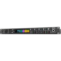
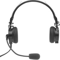
- Configuration 116
- Notices
- Proprietary notice
- Copyright notice
- Warranty notice (limited)
- Factory service center
- Contact information
- Sales
- Customer service repair
- Technical support
- Claims
- Warning
- Notice!
- OpenSSL project
- PC & Network Security consideration
- Introduction
- Features
- System Overview
- Requirements
- - Browser Requirements
- - Network Requirements
- Options
- Supported Serial Control Radio
- EF Johnson
- Hytera
- ICOM NXDN Radios
- iDEN Falcon Series
- Kenwood Radios
- Motorola MOTOTRBO
- PowerTrunk
- Sepura TETRA Radios
- Tait Mobile Radio
- Telex Generic Serial Type Version 1
- Telex Generic Serial Type Version 2
- Supported Signaling
- FleetSync
- Operating Modes
- Controls and Indicators
- Communications System Design
- Communications Control
- Tone Remote Control
- VoIP Radio Control
- Network Security Considerations
- Network Requirements
- IP Operation Overview
- Ethernet as Physical Layer
- Bandwidth
- Multicast
- Internet Group Management Protocol
- Network Performance
- TCP/IP and UDP/IP
- Multicast UDP/IP
- Telex Port-Centric Method
- IP-224 Installation
- Caution!
- IP-224 Rack Mounting
- Connection
- Front Panel Connections
- RADIO 1 and RADIO 2 Jack
- HANDSET Jack
- Back Panel Connections
- Power Terminal
- PRIM Port
- SECOND Port
- ACCESSORY Port
- DB-37 Port
- Configuration
- Browser Setup
- Setting the IP Address Information
- NOTE:
- IP-224 Web Browser Configuration
- Click the OK button.
- Web Setup Windows Standards
- IP-224 Browse Banner
- Home Window
- Device Name Field
- Submit Button
- Ethernet Setup
- Ethernet Port Setup
- Auto Failover Enabled Check Box
- Current Active Port Field
- Set Active Port Radio Button
- Primary Port Column
- Secondary Port Column
- DHCP Enabled Check Box
- Unit IP Address Field
- Subnet Mask Field
- Default Gateway Field
- Ping IP Address Field
- Ping Count
- Ping Timeout
- Time Between Pings
- Auto Failover Web Page Setup
- IPv6 Setup
- IPv6 Enable Check Box
- Link Local Address Field
- Subnet Prefix Length Field
- Gateway Field
- Packet Setup
- Packet Delay Before Playback Field
- QOS Precedence Bits Field
- QOS D, T, and R Bits Field
- CMS Setup
- IP Address Field
- Control Port Field
- SRTP Encryption Check Box
- Authorization Token Field
- SNMPv3 Setup
- SNMPv3 Enable Check Box
- Username Field
- Auth Password Field
- Privacy Password Field
- Change Password Button
- Trap Target 1 - 3 Enable Check Box and IP Address Field
- Telex System Manager Setup
- Enable Check Box
- Multicast Address Field
- Incoming Port Field
- Outgoing Port Field
- TTL Field
- Multicast Setup
- Auto Configuration
- Line Setup
- Line Enable Check Box
- Line Name Field
- Line Type Drop Down Menu
- Serial Type Drop Down Menu
- Vocoder Type Drop Down Menu
- Mcast Enable Check Box
- RX Mcast Address Field
- RX Port Field
- TX Mcast Field
- TX Port Field
- TX Group Port A Field
- TX Group Port B Field
- IP Recorder Setup
- Mcast Address Field
- Hardware Setup
- Line Info
- Audio/Analog Setup
- 2-Wire/4-Wire Audio Drop Down Menu
- RX Audio Single-Ended/Balanced Drop Down Menu
- RX Audio Impedance Drop Down Menu
- TX Audio Single-Ended/Balanced Drop Down Menu
- TX Audio Impedance Drop Down Menu
- Digital I/O Setup
- I/O Pullup/Pulldown/Float Drop Down Menu
- I/O Voltage Drop Down Menu
- Display Setup
- Contrast Drop Down Menu
- Menu Enable Check Box
- Serial Protocol Setup
- Baud Rate Drop Down Menu
- RS485 Address Drop Down Menu
- Serial Protocol Version Drop Down Menu
- Gain Setup
- Line Info
- Analog Recorder Gains
- Analog Recorder Output Gain Slider
- CTCSS Gains
- CTCSS Input Gain Slider
- CTCSS Output Gain Slider
- Handset Gains
- Handset Mic Input Gain Slider
- Handset Sidetone Gain Slider
- Handset Output Gain Slider
- RX AGC Gains
- RX AGC Enabled Check Box
- RX AGC Target Level Slider
- RX/TX Gains
- RX IP Input Gain Slider
- TX IP Input Gain Slider
- TX Monitor Input Gain Slider
- TX Output Gain Slider
- Per Line Setup
- Line Info
- CTCSS Setup
- On With PTT Radio Button
- Off Radio Button
- Delay/Timeout Setup
- RX Delay Field
- TX Delay Field
- PTT Delay Field
- Squelch Tail Delay Field
- Selcall Min. PTT Field
- Ethernet Crossmute Setup
- Function Tone Setup
- Jump To Entry Drop Down Menu
- Boot Up Frequency Drop Down Menu
- Relay Drop Down Menu
- Relay Group Drop Down Menu
- Relay Time (ms) Field
- Digital Output Field
- CTCSS Freq Field
- CTCSS Default Check Box
- System Field
- Chan Field
- Tone Encode Freq 1(Hz) and Tone Encode Freq 2(Hz) Fields
- LAM/COR Setup
- LAM Enable Check Box
- LAM Level Field
- LAM Time Field
- Rx w/PTT Field
- COR Enable Check Box
- COR Active High Check Box
- Options Setup
- F1 Last Call Check Box
- Freq Update w/PTT Check Box
- Full Duplex Check Box
- Hi-Pass RX Check Box
- Monitor Enable Check Box
- Pre-Emphasize TX Check Box
- PTT Notch Filter Check Box
- Scan List Check Box
- Cross Mute Check Box
- PTT Tones Decode Check Box
- PTT Tones Encode Check Box
- Supervisor Check Box
- Relay Setup
- Common to Ground Check Boxes
- Monitor Relay Radio Buttons
- PTT Relay Radio Buttons
- Signaling Setup
- FleetSync Decode Check Box
- FleetSync Encode Check Box
- MDC Decode Check Box
- MDC Encode Check Box
- MSK Tone Delay Field
- MSK Tone Gain Field
- Emerg. Status 1 Field
- Emerg. Status 2 Field
- Tone Setup
- PTT/Notch Freq Drop Down Menu
- Monitor Frequency Field
- Guard Tone Duration Field
- Crosspatch Setup
- Local Setup
- Line-Line Crosspatch Drop Down Menu
- Start Patch FTone Drop Down Menu
- Stop Patch FTone Drop Down Menu
- Network Setup
- Ethernet Patch Timeout Field
- Account Management
- User Accounts
- IMPORTANT:
- To edit a User Account, do the following:
- System Parameters
- Internal Storage
- Name Field
- Backup Button
- Available Backups List
- Name Column Display
- Time Column Display
- Version Column Display
- Restore Button
- Delete Button
- Click the Restore button.
- To delete a backup from the IP-224 persistent storage, do the following:
- External Storage
- Restore Settings from a File Field
- Browse Button
- To save a new backup to the local computer, do the following:
- Firmware Upgrade
- Firmware File Field
- Upgrade Status
- Status Text
- Progress Bar
- Download Telex Firmware
- Update Firmware Tool Window
- File Field
- Firmware File Info Group Box
- Device Type Field
- Date Field
- Firmware Version Field
- Checksum Field
- Destination Group Box
- Left Navigation Pane
- Manual Entry Field
- Login Group Box
- Password Field
- Write Firmware Button
- Close Button
- Upload VoIP Hardware Firmware
- Additional Features Window
- Save Parameters
- Save Parameters Button
- Reset IP-224 Button
- System Status
- Ethernet Port Status
- Level Status
- Handset Input Field
- Line 1 Column
- Line 2 Column
- CTCSS Input Field
- RX IP Input Field
- RX Input Field
- TX IP Input
- TX Monitor Input
- Serial Connection State
- Type Field
- State Field
- Operation
- Front Panel
- Front Panel Display
- Front Panel Softkeys
- MENU Softkey
- IC Softkey
- Arrow Up Softkey
- Arrow Down Softkey
- Main Menu
- System Utilities
- View Unit Info Menu
- Display Contrast Menu
- Remote Access
- Reboot IP-224 Menu
- Network Settings
- Auto Failover Check Box
- Primary Port Menu
- Secondary Port Menu
- DHCP Check Box
- Set IP Address Menu
- Set Subnet Mask Menu
- Set Gateway Menu
- Set Ping IP Address Menu
- Set Ping Count Menu
- Set Ping Timeout Menu
- Set Time Btwn Pings Menu
- Active Port Menu
- Input VU Meters
- RX Input Levels Menu
- CTCSS Input Levels Menu
- RX IP Input Levels Menu
- TX IP Input Levels Menu
- TX Mon Input Levels Menu
- Handset Mic Level Menu
- Gain Adjustment
- TX Output Gains Menu
- RX Input Gains Menu
- TX IP Input Gains Menu
- RX IP Input Gains Menu
- TX Mon Input Gains Menu
- CTCSS Input Gains Menu
- CTCSS Output Gains Menu
- Rec Output Gains Menu
- Handset Gains Menu
- Factory Mode
- Factory Mode Screen
- Reset Accounts Check Box
- Factory Defaults Check Box
- Console Mode
- System Operation
- Console PTT
- Radio Receive
- Hardware Installation
- Configuration
- Under Line Setup
- Under Audio/Analog Setup
- Under Ethernet Crossmute Setup
- Under Function Tone Setup
- Under LAM Setup
- LAM SETUP
- Under Optional Setup
- OPTIONS SETUP
- Under Tone Setup
- Maintenance
- IP-224 Main Board Service
- TELEX
Brand : Telex
Model : IP-224
Category : Radio