Airman 750 - Headset Telex - Free user manual and instructions
Find the device manual for free Airman 750 Telex in PDF.


| Product Type | Aviation Headset |
| Brand | Telex |
| Model | Airman 750 |
| Connectivity | Wired with dual plug (PJ-068 and PJ-055) |
| Impedance | 150 ohms per ear |
| Frequency Response | 100 Hz - 10 kHz (microphone), 100 Hz - 6 kHz (speaker) |
| Noise Attenuation | Passive NRR 23 dB |
| Microphone Type | Electret condenser, noise-cancelling |
| Microphone Impedance | 500 ohms |
| Weight | 340 g (12 oz) |
| Headband | Adjustable, padded |
| Earcups | Over-ear, foam-filled, leatherette cushions |
| Cable Length | 5 ft (1.5 m) straight cable |
| Features | Volume control, noise-cancelling microphone, gel-filled earpads |
| Maintenance | Clean with mild soap and water; avoid solvents |
| Safety | Compliant with ANSI S3.19-1974 (hearing protection) |
| Warranty | 1 year limited |
| Certification | FCC Part 15 |
Frequently Asked Questions - Airman 750 Telex
User questions about Airman 750 Telex
0 question about this device. Answer the ones you know or ask your own.
Ask a new question about this device
Download the instructions for your Headset in PDF format for free! Find your manual Airman 750 - Telex and take your electronic device back in hand. On this page are published all the documents necessary for the use of your device. Airman 750 by Telex.
USER MANUAL Airman 750 Telex
natural_image
Black-and-white photo of a dual-camera headset with earbuds and antenna (no text or symbols visible)en
Customer Maintenance Manual
Table of contents
| 1 | General information 5 | |
| 1.1 Record of Revisions 5 | ||
| 1.2 Purpose of manual 5 | ||
| 1.3 Technical support 5 | ||
| 1.4 Parts ordering 5 | ||
| 1.5 Repairs 6 | ||
| 2 | Description and specifications 7 | |
| 2.1 General description 7 | ||
| 2.2 Models covered 7 | ||
| 2.3 Specifications 8 | ||
| 3 | Parts list 10 | |
| 3.1 General 10 | ||
| 3.2 Airman 760, catalog number 64400-200 10 | ||
| 3.3 Airman 750, catalog number 64300-200, -205, -208, -210, -212, -218, -219, -220, and -300 11 | ||
| 4 | Disassembly and assembly | 14 |
| 4.1 Disassembly | 14 | |
| 4.1.1 | Removal of the receiver assembly | 14 |
| 4.1.2 | Removal of the cord assembly 15 | |
| 4.1.3 | Removal of the circuit board and boom assembly (Airman 750) | 16 |
| 4.1.4 | Removal of a glider | 16 |
| 4.2 Assembly | 16 | |
| 5 | Wiring and connectors | 17 |
| 5.1 Airman 750 wiring diagrams | 17 | |
| 5.1.1 | Catalog numbers 64300 -200, -220, -300 | 17 |
| 5.1.2 | Catalog number 64300 -210 | 18 |
| 5.1.3 | Catalog numbers 64300 -205, -208 | 18 |
| 5.1.4 | Catalog number 64300 -212 | 19 |
| 5.1.5 | Catalog number 64300 -218 | 19 |
| 5.1.6 | Catalog number 64300 -219 | 20 |
| 5.2 Airman 760 wiring diagrams | 20 | |
| 5.2.1 | Catalog number 64300 -200 | 20 |
| 5.3 Airman 750 connectors | 20 | |
| 5.3.1 | Connector view for catalog numbers 64300-200, -212, -300 | 20 |
| 5.3.2 | Connector view for catalog numbers 64300-205, -208, -210 | 21 |
| 5.3.3 | Connector view for catalog number 64300-218 | 21 |
| 5.3.4 | Connector wiring diagram for catalog number 64300-219 | 22 |
| 5.3.5 | Connector wiring diagram for catalog number 64300-220 | 22 |
| 5.4 Airman 760 connectors | 22 | |
| 5.4.1 | Connector view for catalog number 64400-200 | 22 |
| 6 | Maintenance | 24 |
| 6.1 Microphone validation and adjustment | 24 | |
| 6.1.1 | Microphone and amplifier sensitivity check | 24 |
| 6.1.2 | Microphone sensitivity adjustment | 25 |
| 6.1.3 | Microphone total harmonic distortion (THD) test | 26 |
| 6.2 Circuit board - 200/300 Series Airman 750 | 26 | |
| 6.2.1 | Testing the circuit board assembly | 26 |
| 6.3 Speaker validation 26 | ||
| 6.3.1 | Speaker sensitivity and frequency response verification | 26 |
7 Troubleshooting 29
7.1 Troubleshooting chart 29
1 General information
1.1 Record of Revisions
| Rev No Revision Date Change Description | |
| A 12/1988 | See previous revisions of 38108-965 for affected changes |
| B 06/1989 | |
| C 01/1990 | |
| D 11/1993 | |
| E 03/1995 | |
| F 04/1996 | |
| G 06/2000 | |
| 7 07/2017 This document was completely rewritten and a Bosch part number (F.01U.311.532) was assigned. | |
| 8 09/2017 – Updated revision on front cover– Removed the Insertion Date column from this table– Technical Support Contact information updated– In the models covered table, updated part number type-o | |
| 9 08/2018 – Minor formatting and parts list update | |
| 10 04/2022 – Update format | |
1.2 Purpose of manual
This manual, Bosch part number F.01U.311.532, contains information for the overhaul and servicing of the Airman 750/760 headset.
1.3 Technical support
A liaison between the customer and factory is provided by the Bosch Product Support Department. Consultation and assistance on technical problems, part information, and availability of local and factory repair facilities is available. When writing, include all information concerning problem and mail to:
Bosch Communications, LLC
8601 Cornhusker Hwy
Lincoln, NE 68506 U.S.A.
Attn: Aircraft Product Support Mgr.
Telephone: 877 863 4188
1.4 Parts ordering
Replacement parts may be ordered from our parts department. When ordering, please include the following information:
- Model Number
- Part Description
- Part Number
- Quantity
Mail to:
Bosch Communications, LLC
8601 Cornhusker Hwy
Lincoln, NE 68507 U.S.A.
Attn: Parts department
Telephone: 800 553 5992
Fax: 402 467 3279
E-mail: repair.lincoln@us.bosch.com
1.5 Repairs
In order to maintain the FAA certification, all repairs to the headset must be made only by persons authorized under Part 43 of the Federal Aviation Agency regulations. Bosch offers full support and repair.
2 Description and specifications
2.1 General description
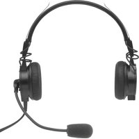
The Telex Airman 750 Headset and the Airman 760 Headphone are designed and engineered for high-quality aircraft communications. The Airman 750 is approved for aircraft use under the Federal Aviation Agency TSO C57a and C58a. The Airman 760 is approved for aircraft use under the Federal Aviation Agency TSO C57a.
The Airman 750 Headset features a miniature, noise-canceling electret microphone element which provides superior hum rejection. The microphone is mounted upon a boom which pivots 310 degrees for use on either side of the user's head. The headset amplifier has an adjustable gain control and provides output levels equivalent to carbon microphone levels. Several variations of the 750 headset exist; each model has a different connector and a unique wiring diagram.
The Airman 760 Headphone is designed for users who operate hand-held microphones. The 760 is virtually identical to the 750 headset, without the boom microphone.
2.2 Models covered
| Model Number Description Connector | ||
| Airman 750 | ||
| 64300-200 Double | side headset, 2x PJ, 150 Ω PJ-068/PJ-055 (or equivalent) | |
| 64300-205 Double | side headset, 2x A5M, 150 Ω XLR 5-pin Male | |
| 64300-208 Double | side headset, 2x A5M, 150 Ω, 7ft | XLR 5-pin Male |
| 64300-210 Double | side headset, 2x A5M, 600 Ω XLR 5-pin Male | |
| 64300-212 Double | side headset, 2x PJ, 600 Ω PJ-068/PJ-055 (or equivalent) | |
| 64300-218 Double | side headset, 2x PJ, 150 Ω, 8ft PJ-068 (or equivalent) | |
| 64300-219 Double | side headset, 2x A4F, 150 Ω XLR 4-pin Female | |
| 64300-220 Double | side headset, 2x PJ, 150 Ω PJ-068/PJ-055 (or equivalent) | |
| 64300-2300 Single | side headset, 2x PJ, 300 Ω PJ-068/PJ-055 (or equivalent) | |
| Airman 760 | ||
| 644-200 Double side | headphone, PJ, 150 Ω PJ-055 (or equivalent) | |
Table 2.1: Airman 750/760 Models and Connector

Notice!
Model 644-000, -203 and Models 64300-00, -005, -105, -008, -108, -010, -110, -012, -112, -016, -116, -018, -118, -019, -119, -020, -021, -121, -022, -122, -201, -216 are no longer supported and are not covered in this CMM.
2.3 Specifications
Receivers
Type: Dynamic
Impedance: 150
64300-200, -205, -208, -218, -219, -220;
64400-200
300 Ω
64300-300
600 Ω
64300-210,-212
Frequency response: 100 Hz to 3000 Hz
Sensitivity: 90 dB SPL ±5 dB at 1 kHz, 1 mW input
Microphone (Airman 750 only)
Type: Noise-canceling amplified electret
Matching impedance: 50 to 600 Ω
Frequency response (Airman 750): 300 Hz to 5000 Hz within limits shown below
Sensitivity: Ref. 1 V/μbar @1 kHz, 12 VDC
- 51 +3/-3 dB (all versions except -220)
-44+2/-1dB(-220)
Total Harmonic Distortion (THD): Less than 5% from 350 Hz to 6000 Hz when the microphone is exposed to 114 dB SPL input.
Operating voltage: 8 to 16 VDC (470 Ohm load)

line
| Frequency (Hz) | Series 1 (dB) | Series 2 (dB) | |---|---|---| | 100 | -10 | -35 | | 300 | 0 | -15 | | 100 | 5 | -10 | | 1k | 5 | -5 | | 2k | 5 | -5 | | 2.5k | 7 | -5 | | 3.5k | 7 | -5 | | 6k | 7 | -5 | | 10k | -5 | -5 |MICROPHONE FREQUENCY RESPONSE
Figure 2.1: Microphone Frequency Response
Approximate gross weight
| Airman 750 Airman 760 | ||
| Single-sided 4 oz. (113 g) 3 oz. | (85 g) | |
| Double-sided | 4.8 oz. (136 g) |
Approximate wearing weight
| Airman 750 Airman 760 | ||
| Single-sided 2.3 oz. (65 g) 2.2 | oz. (62 g) | |
| Double-sided 3.2 oz. (91 g) |
Plug type
Varies by model. Refer to Models covered, page 7.
Cord length
Varies by model. Refer to Disassembly and assembly, page 14.
3 Parts list
3.1 General
When replacing parts, consult the illustration, Airman 760, catalog number 64400-200, page 10 and Airman 750, catalog number 64300-200, -205, -208, -210, -212,-218, -219, -220, and -300, page 11. Choose the parts corresponding to the catalog/model.

Figure 3.1: Airman 750/760 series-200/300 exploded view
3.2 Airman 760, catalog number 64400-200
| Item Ordering Part Number Description Model | -200 | ||
| 1 59040 | 4360 SCRW PT, PAN HEAD, K15 X 6MM, BLK ZINC 4 | ||
| 2 59040 | 2002 EAR CUSHION (1 per pkg.) 2 | ||
| 800456055OR64301000 | EAR CUSHION (2 per pkg.) 1 | ||
| 3 70133 | 35000 CUSHION PAD 2 | ||
| 4 63988 | 8002 CORD | LENGTH: 5.5 ± 0.2 ft. ( 1.68 ± 0.15 m) | 1 |
| 5 590637000 CLOTHING CLIP 1 | |||
| 8 64308100 HOUSING (Receiver) ASSY PACKAGED, left side 1 | |||
| 9 64308110 HOUSING (Receiver) ASSY PACKAGED, right 1 | |||
| 10 64404018 HOUSING REAR, right side no printing 1 | |||
| 11 S-64318081 HEADBAND ASSEMBLY 1 | |||
| 12 64310000 GLIDER ASSEMBLY 2 | |||
| 13 64330500 GLIDER SPRING | |||
| 14 Not Available as a replaceable part | CIRCUIT BOARD | 1 | |
| 15 F01U327242 HOUSING REAR, LEFT SIDE 1 | |||
3.3
Airman 750, catalog number 64300-200, -205, -208, -210, -212, -218, -219, -220, and -300
| Item | Ordering Part Number | Description | Models | ||||||||
| 200 | 205 | 208 | 210 | 212 | 218 | 219 | 220 | 300 | |||
| 1 | 590404360 | SCREW, PT, PAN HEAD, K15 X 6MM, BLK ZINC | 4 | 4 | 4 | 4 | 4 | 4 | 4 | 4 | 2 |
| 2 | 590402002 | EAR CUSHION (1 per pkg.) | 2 | 2 | 2 | 2 | 2 | 2 | 2 | 2 | 1 |
| 8004560005OR64301000 | EAR CUSHION (2 per pkg.) | 1 | 1 | 1 | 1 | 1 | 1 | 1 | 1 | ||
| 3 | 701335000 | CUSHION PAD | 2 | 2 | 2 | 2 | 2 | 2 | 2 | 2 | 1 |
| 4 | 70113002 | CORDApproximate Length:5.5 ft. (1.67 m) | 1 | 1 | |||||||
| 63988018 | CORDApproximate Length:5.8 ft. (1.76 m) | 1 | |||||||||
| Item | Ordering Part Number | Description Models | |||||||||
| 63988025 C | ORD Approximate Length: 7 ft. (2.13 m) | 1 | |||||||||
| 63988031 C | ORD Approximate Length: 6 ft. (1.82 m) | 1 | |||||||||
| 70413002 C | ORD Approximate Length: 5.5 ft. (1.67 m) | 1 | |||||||||
| 63988043 C | ORD Approximate Length: 8 ft. (2.4 m) | 1 | |||||||||
| S-F01U327247 | CORD 1 | ||||||||||
| 70413006 C | ORD Approximate Length: 5.5 ft. (1.67 m) | 1 | |||||||||
| 5 590 | 637000 | CLOTHING CLIP 1 1 2 1 1 1 1 1 1 1 | |||||||||
| 8 643 | 08100 HOUS | ING (Receiver) ASSY PACKAGED, left side | 1 1 1 | ||||||||
| 64308108 H | OUSING (Receiver) ASSY PACKAGED, left side | 1 | |||||||||
| 64308115 H | OUSING (Receiver) ASSY PACKAGED, left side | 1 1 1 1 | |||||||||
| 64308117 H | OUSING (Receiver) ASSY PACKAGED, left side | 1 | |||||||||
| 9 643 | 08110 HOUS | ING (Receiver) ASSY PACKAGED, right side | 1 1 1 1 1 1 1 1 | ||||||||
| 10 64 | 404018 HOUS | SING REAR, right side 1 1 1 1 | 1 1 1 1 | ||||||||
| ESP-F01U323856 | HOUSING REAR, right side (printed) | ||||||||||
| 11 64 | 318069 HEAD | DBAND ASSEMBLY 1 | |||||||||
| 64318070 H | EADBAND ASSEMBLY 1 | ||||||||||
| 63993010 H | EADBAND ASSEMBLY 1 | ||||||||||
| 64318071 H | EADBAND ASSEMBLY | 1 | |||||||||
| S064318071 | HEADBAND ASSEMBLY 1 | ||||||||||
| 64318074 H | HEADBAND ASSEMBLY 1 | ||||||||||
| S-F01U327241 | HEADBAND ASSEMBLY 1 | ||||||||||
| S-64318075 | HEADBAND ASSEMBLY 1 | ||||||||||
| 64318085 H | HEADBAND ASSEMBLY 1 | ||||||||||
| 12 64 | 310000 GLIDER ASSEMBLY 2 2 2 2 2 2 2 2 2 2 2 2 2 2 2 2 2 2 2 2 2 2 2 2 2 2 2 2 2 2 2 2 2 2 2 2 2 2 2 2 2 2 2 2 2 2 2 2 2 2 1 | ||||||||||
| 13 64 | 305000 GLIDER SPRING 1-piece 2 2 2 2 2 2 2 2 2 2 2 2 2 2 2 2 2 2 2 2 2 2 2 2 2 2 2 2 2 2 2 2 2 2 2 2 2 2 2 2 2 2 2 2 2 2 2 2 2 3 | ||||||||||
| S-F01U327240 | GLIDER SPRING 10-piece | ||||||||||
| 14 60 | 0578000 | PCBA 1 1 1 1 1 1 1 1 1 1 1 1 1 1 1 1 1 1 1 1 1 1 1 1 1 1 1 1 1 1 1 1 1 1 1 1 1 1 1 1 1 1 1 1 1 1 1 1 1 1 3 | |||||||||
| 15 64 | 307008 BOOM ASSEMBLY 1 1 1 1 1 1 1 1 1 1 1 1 1 1 1 1 1 1 1 1 1 1 1 1 1 1 1 1 1 1 1 1 1 1 1 1 1 1 1 1 1 1 1 1 1 1 1 1 1 2 | ||||||||||
| 64307013 BOOM ASSEMBLY 1 | 1 | 1 | 1 | 1 | |||||||
| 16 59 | 688000 WINDSCREEN 1 1 1 1 1 1 1 1 1 1 1 1 1 1 1 1 1 1 1 1 1 1 1 1 1 1 1 1 1 1 1 1 1 1 1 1 1 1 1 1 1 1 1 1 1 1 1 1 1 4 | ||||||||||
| 800456001 | WINDSCREEN + O-RING | 1 1 1 1 1 1 1 1 1 1 1 1 1 1 1 1 1 1 1 1 1 1 1 1 1 1 1 1 1 1 1 1 1 1 1 1 1 1 1 1 1 1 1 1 1 1 1 1 1 1 | |||||||||
| 17^a | 580001003 | OPTIONAL O-RING | 1 1 1 1 1 1 1 1 1 1 1 1 1 1 1 1 1 1 1 1 1 1 1 1 1 1 1 1 1 1 1 1 1 1 1 1 1 1 1 1 1 1 1 1 1 1 1 1 | ||||||||
| 18 70 | 531004 TEMPLE PLATE | 1 | |||||||||
| 20 70 | 533000 TEMPLE PLATE FOAM PAD | 1 | |||||||||
| 21^b | 701246000 | BOOM ROTATOR CAP | 1 1 1 1 1 1 1 1 1 1 1 1 1 1 1 1 1 1 1 1 1 1 1 1 1 1 1 1 1 1 1 1 1 1 1 1 1 1 1 1 1 1 1 1 1 1 1 1 1 3 | ||||||||
| 22 S-F01U322242 | OVERHEAD CORD | 1 1 1 1 1 1 1 1 1 1 1 1 1 1 1 1 1 1 1 1 1 1 1 1 1 1 1 1 1 1 1 1 1 1 1 1 1 1 1 1 1 1 1 1 1 1 1 1 1 4 | |||||||||
^a Windscreen (59688000) is standard equipment. Optionally, windscreen + o-ring (800456001) can be used.
^b Not shown. Included as part of item 15 (Boom Assembly) or can be purchased separately.
4 Disassembly and assembly
The following procedure allows for complete disassembly of the Airman 750 and Airman 760. Refer to the illustration and to Parts list, page 10.

Figure 4.1: Airman 750/760 series-200/300 exploded view

Notice!
Assembly is the reversal of the disassembly procedure. Please take care when disassembling to note details that may be required in the assembly process, such as the locations of disconnected wires.
When soldering, be careful not to touch the plastic housing of the headset/headphone with the soldering iron.
4.1 Disassembly
4.1.1 Removal of the receiver assembly
To remove the receiver assembly, do the following:
-
Gently remove the foam ear cushion (2) (and ear cushion pad if present).
-
Using a Torx-5 screwdriver, remove the two screws (1) from the receiver assembly (8, 9).
The rear housing separates from the receiver assembly and the headband.

Notice!
Do not pull the receiver assembly more than 12 mm away from the rear housing at this time.
- For the cord side, using a soldering iron, carefully disconnect the red and white internal wires from either the circuit board or the receiver assembly.
OR
For the non-cord side, continue to the next step.
- Using a soldering iron, carefully disconnect the overhead cord wires from the receiver assembly.

Figure 4.2: Circuit board / Receiver / Cord Wiring

Notice!
Airman 750 model -300 does not have overhead cord wires.
4.1.2 Removal of the cord assembly
To remove the cord assembly, do the following:
- Gently remove the foam ear cushion (2) (and ear cushion pad if present).
- Using a Torx-5 screwdriver, remove the two screws (1) from the receiver assembly (8, 9). The rear housing separates from the receiver assembly and the headband.

Notice!
Do not pull the receiver assembly more than 12 mm away from the rear housing at this time.
- For the cord side, using a soldering iron, carefully disconnect the red and white internal wires from either the circuit board or the receiver assembly.
OR
For the non-cord side, continue to the next step.
- Using a soldering iron, on the circuit board carefully disconnect the four wires from the cord assembly (4).
4.1.3 Removal of the circuit board and boom assembly (Airman 750)
To remove the circuit board, do the following:
-
Follow steps 1 to 2 in the procedure for removing the cord assembly. Refer to Removal of the cord assembly, page 15.
-
If disassembling an Airman 750, use a soldering iron on the circuit board to carefully disconnect the two boom wires from J10 and J11.
OR
If disassembling an Airman 760, continue to next step.
- Pull back the black clasps on the side of the circuit board to release it for removal. The 750 boom assembly is now free of all headset components.

Notice!
Appearances vary slightly for some versions. Refer to Parts list, page 10 for part number descriptions and ordering number.
4.1.4 Removal of a glider
To remove a glider from the headset, do the following:
- Using a pair of needle nose pliers, straighten the crimp at the end of the glider.
- Once the crimp is straightened, gently slide the slider through the glider stabilizer.

Notice!
Take care not to lose the glider spring (a small curved rectangular piece of plastic). The glider spring provides tension to hold the glider in place when mounted in the headset. The outward facing arc should be touching the glider providing some tension.
- Repeat steps 1 and 2 for dual-sided headset models.
For a complete list of wiring diagram information, refer to Wiring and connectors, page 17.
4.2 Assembly

Notice!
Assembly is a reversal of the disassembly procedure. Steps need to be done exactly the reverse order of the disassembly procedure to ensure proper headset fit and operation. Please take care to properly align parts and wires to ensure proper operation. See disassembly procedure, parts lists, assembly diagrams, and wiring diagrams for reference.

Notice!
Speaker wires and overhead cord must be routed around the perimeter of the magnet in the receiver assembly to ensure they do not get pinched between the circuit board and the speaker.
5 Wiring and connectors
5.1 Airman 750 wiring diagrams

Notice!
On the speaker, the positive terminal is usually indicated with a dot.
5.1.1 Catalog numbers 64300 -200, -220, -300

Notice!
With model -300 omit overhead cordage.

Figure 5.1: Airman 750 Headset Model -200, -220, -300 Wiring Diagram
5.1.2 Catalog number 64300 -210

Figure 5.2: Airman 750 Headset Model -210 Wiring Diagram
5.1.3 Catalog numbers 64300 -205, -208

Figure 5.3: Airman 750 Headset Model -205, -208 Wiring Diagram
5.1.4 Catalog number 64300 -212
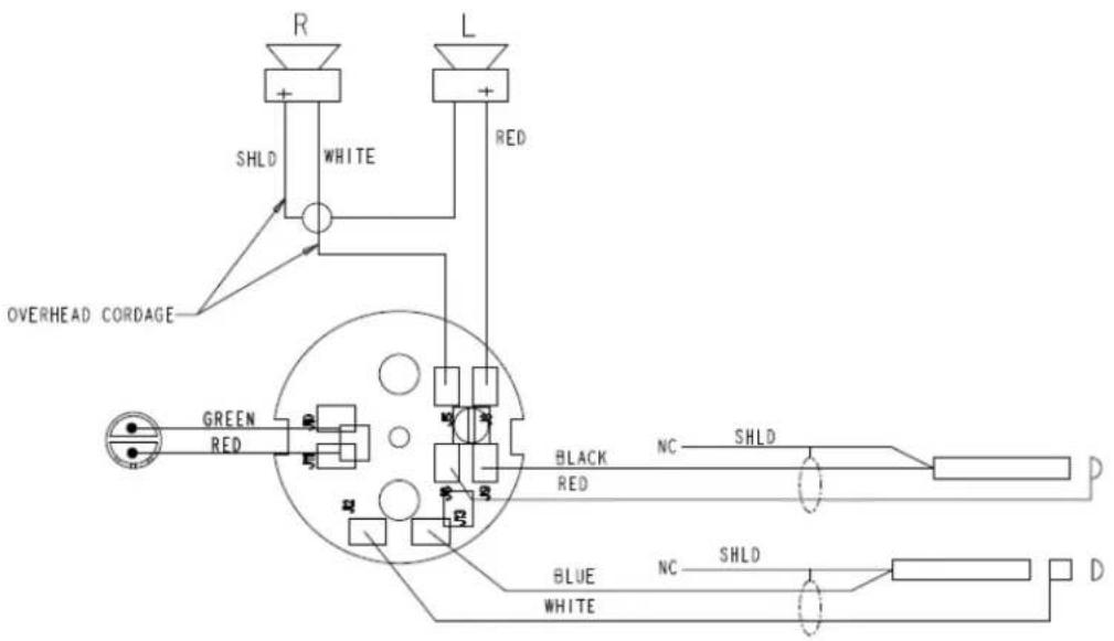
Figure 5.4: Airman 750 Headset Model -212 Wiring Diagram
5.1.5 Catalog number 64300 -218
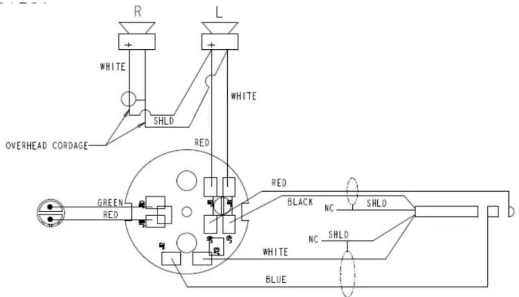
Figure 5.5: Airman 750 Headset Model -218 Wiring Diagram
5.1.6 Catalog number 64300 -219

Figure 5.6: Airman 750 Headset Model -219 Wiring Diagram
5.2 Airman 760 wiring diagrams
5.2.1 Catalog number 64300 -200

Figure 5.7: Airman 760 Headphone Model -200 Wiring Diagram
5.3 Airman 750 connectors
5.3.1 Connector view for catalog numbers 64300-200, -212, -300
Microphone: .206 in (5.2 mm) DIA.
Receiver: .250 in (6.4 mm) DIA.

natural_image
Two types of electrical connectors with internal circuitry, no text or symbols presentFigure 5.8: PJ068 and PJ055 Connector, 750 Model -200, -212, -300

Figure 5.9: PJ068 and PJ055 Connector Wiring, 750 Model -200, -212, -300
5.3.2 Connector view for catalog numbers 64300-205, -208, -210
XLR connector: Neutrik 5MC or equivalent

natural_image
Simple line drawing of a screwdriver with a handle and pointed tip (no text or symbols)Figure 5.10: XLR Connector, 750 Model -205, -208, -210

Figure 5.11: XLR Connector Wiring, 750 Model -205, -208, -210
5.3.3 Connector view for catalog number 64300-218
PJ-068: .206 in (5.2 mm) DIA.

natural_image
Pure electrical circuit lines without any symbolsFigure 5.12: PJ-068 Connector, 750 Model -218

Figure 5.13: PJ-068 Connector Wiring, 750 Model -218
5.3.4 Connector wiring diagram for catalog number 64300-219
XLR connector: Neutrik NC4FX or equivalent

natural_image
Simple line drawing of a tool handle (no text or symbols)Figure 5.14: XLR Connector, 750 Model -219
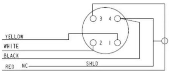
Figure 5.15: XLR Connector Wiring, 750 Model -219
5.3.5 Connector wiring diagram for catalog number 64300-220
Microphone: .206 in (5.2 mm) DIA. right angle
Receiver: .250 in (6.4 mm) DIA. right angle

natural_image
Pure electrical connector diagram without any text, numbers, or symbolsFigure 5.16: PJ068 and PJ055 Connector, 750 Model -220

Figure 5.17: PJ055 and PJ068 Connector Wiring, 750 Model -220
5.4 Airman 760 connectors
5.4.1 Connector view for catalog number 64400-200
PJ-055: .25 in (6.4 mm) DIA.

natural_image
Pure electrical circuit lines without any symbolsFigure 5.18: PJ-055 Connector, 460 Model -200

Figure 5.19: PJ-055 Connector Wiring, 760 Model -200
6 Maintenance
6.1 Microphone validation and adjustment
6.1.1 Microphone and amplifier sensitivity check
Headset specifications are designed to comply with FAA TSO C-57a, C-58a, including RCTA DO-170 and DO-160D.
To test the sensitivity of the microphone, do the following:
- Construct a test circuit. For more information, see Figure 1.
- Connect the test circuit to the microphone plug of the headset. For more information, refer to Models covered, page 7.

Figure 6.1: Airman 750 Headset Boom Microphone Sensitivity Check Test Circuit
- Calibrate a lab microphone.
- Place the calibrated lab microphone 1/4 inch (6 mm) above an artificial mouth (Bruel and Kjaer type 4219).
- Connect a signal generator to the artificial mouth.
- Adjust for an output of 100 dBspl or of 114 dBspl @ 1/4 inch from the opening to the lab microphone.
- Remove the lab microphone.
- Position the headset boom microphone 1/4 inch (6 mm) above the output of the artificial mouth.

Notice!
The acoustic hole in the boom mic should be aligned with the center of the artificial mouth opening. Windscreens should be removed for this test.
- Measure the output of the headset microphone with a digital voltmeter.
Artificial mouth output Microphone sensitivity specification
| All versions except -220: @100 dB | 63 mVrms +16/-7 mVrms |
| @114 dB | 316 mVrms +82/-34 mVrms |
| For -220 use: @100 dB | 126 mVrms +33/-14 mVrms |
| @114 dB | 631 mVrms +163/-169 mVrms |
Table 6.2: Microphone sensitivity specifications
6.1.2 Microphone sensitivity adjustment
Microphone sensitivity is adjusted by turning the gain adjustment control, using a small screwdriver through the opening in the left outer housing assembly. The screwdriver connects with the gain adjustment potentiometer (R11) on the circuit board. Clockwise adjustment increases output level.

natural_image
Technical line drawing of a mechanical component with a tool and circular feature (no text or symbols)Figure 6.2: Gain Adjustment Control

For Internal Reference Only
Figure 6.3: Gain Adjustment Potentiometer (R11)
Final sensitivity at 1 kHz shall be set with gain adjust potentiometer R11. Refer to Microphone and amplifier sensitivity check, page 24.
6.1.3 Microphone total harmonic distortion (THD) test
- Calibrate the sound pressure to be 114 dB SPL at 6 mm from an artificial mouth.
- Measure the THD of the microphone placed at that location using the same test circuit.
It meets the TSO spec when THD is less than 5% from 350 Hz to 6000 Hz.
6.2 Circuit board - 200/300 Series Airman 750
The same circuit board is used in all 200 and 300 Series versions of the Airman 750 Headset. Circuit boards may be tested while outside of the headset chassis using the following test circuit:
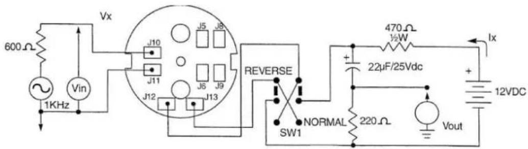
- Specifications apply with SW1 in both normal and reverse positions.
Specifications - Vin = 0.47mVAC, 1000 Hz
- lx = 17 ± 2mA
- Vout = 297 - 592 mV
When pot is set to midpoint.
Figure 6.4: Test circuit for Airman 750
6.2.1 Testing the circuit board assembly
To test the circuit board assembly, do the following:
- Construct the test circuit.
- Connect the circuit board to the test circuit.
- Remove the circuit board and wiring completely from the headset.
- Set Vin to measure 0.47 mVAC, 1Khz, VOUT should read 297-592 mV, when pot is set to midpoint.
If the output is outside this range, replace the circuit board. Specifications apply with SW1 in both normal and reverse positions.
6.3 Speaker validation
6.3.1 Speaker sensitivity and frequency response verification
Transducer type Dynamic
Sensitivity (All Models) 104 dB SPL ±5 dB at 1 kHz, 1 mW
input to headset, at LOW volume control setting. 1 mW based on input impedance of headset being tested.
Frequency response Must meet standards outlined in the
specifications.
Earphone testing for the Airman 750 and 760 is done on a flat plate coupler.
To measure the speaker, do the following:
-
Calibrate a lab microphone.
-
Connect an audio analyzer to the lab microphone.
- Place the calibrated lab microphone under the flat plate coupler and up through the hole, flush to the microphone positioning flange.

Figure 6.5: Flat Plate Coupler
- Place the speaker (without the foam ear cushion or pad) flush to the top of the flat plate coupler, centered over the hole.
- Use a constant voltage sine wave generator with a 50 Ω output impedance to supply the speaker with a 1 mW, 1 KHz signal to the appropriate connector. For more information, refer to Models covered, page 7.

Notice!
Once the headset/headphone is connected to the constant voltage sine wave generator, the output voltage can be measured at the sine wave generator or by the audio analyzer connected to the lab microphone.
6. Adjust the voltage across the headset per the following table.
| VERSION VOLTAGE AC | ROSS HEADSET PLUG | SPEAKER WIRING IMPEDANCE |
| 64300-200, -205,-208,-218, -219, -22064400-200 | .39 VRMS Parallel 150 Ω | |
| 64300-300 .39 VRMS Stereo 300 Ω | ||
| 64300-210, -212 .77 VRMS Series 600 Ω |
Table 6.3: Headset/headphone voltage, speaker wiring, and impedance
- Measure the acoustic output of the headset, using the audio analyzer OR the constant voltage sine wave generator.

Notice!
Earphone sensitivity @1 kHz should be 104 ±5 dB on the earphone.
- Measure and record the acoustic output over the frequency range of 350 Hz to 3 KHz.

Notice!
The resultant curve should fit the limits as defined in Description and specifications, page 7.
- Repeat steps 1 through 8 with the second speaker, if applicable.
7 Troubleshooting
7.1 Troubleshooting chart
| Check plug(s) | Check amplifier | Check cord | Check boom mic assembly and internal wiring | Check speaker(s) and internal wiring | Check amplifier gain adjust | |
| Receiver inoperative | X X X | |||||
| Microphone inoperative | X X X X | |||||
| Receiver intermittent | X X X | |||||
| Microphone intermittent | X X X X | |||||
| Distorted receiver signal | X | |||||
| Distorted microphone signal | X X X | |||||
| Microphone level cannot be adjusted properly | X X X |

natural_image
Front view of a white aircraft fuselage with visible structural details and window grilles, mounted on a concrete wall (no text or symbols)Bosch Security Systems, LLC
130 Perinton Parkway
Fairport, NY 14450
USA
www.boschsecurity.com
© Bosch Security Systems, LLC, 2022
- Troubleshooting 29
- General information
- Record of Revisions
- Purpose of manual
- Technical support
- Bosch Communications, LLC
- Parts ordering
- Repairs
- Description and specifications
- General description
- Models covered
- Notice!
- Specifications
- Receivers
- Microphone (Airman 750 only)
- Plug type
- Cord length
- Parts list
- General
- Airman 760, catalog number 64400-200
- Disassembly and assembly
- Disassembly
- Removal of the receiver assembly
- Removal of the cord assembly
- Removal of the circuit board and boom assembly (Airman 750)
- Removal of a glider
- Assembly
- Wiring and connectors
- Airman 750 wiring diagrams
- Catalog numbers 64300 -200, -220, -300
- Catalog number 64300 -210
- Catalog numbers 64300 -205, -208
- Catalog number 64300 -212
- Catalog number 64300 -218
- Catalog number 64300 -219
- Airman 760 wiring diagrams
- Catalog number 64300 -200
- Airman 750 connectors
- Connector view for catalog numbers 64300-200, -212, -300
- Connector view for catalog numbers 64300-205, -208, -210
- Connector view for catalog number 64300-218
- Connector wiring diagram for catalog number 64300-219
- Connector wiring diagram for catalog number 64300-220
- Airman 760 connectors
- Connector view for catalog number 64400-200
- Maintenance
- Microphone validation and adjustment
- Microphone and amplifier sensitivity check
- Microphone sensitivity adjustment
- For Internal Reference Only
- Microphone total harmonic distortion (THD) test
- Circuit board - 200/300 Series Airman 750
- Testing the circuit board assembly
- Speaker validation
- Speaker sensitivity and frequency response verification
- Troubleshooting
- Troubleshooting chart
- Bosch Security Systems, LLC
- www.boschsecurity.com
Brand : Telex
Model : Airman 750
Category : Headset