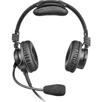
AIRMAN 7P - Headphones Telex - Free user manual and instructions
Find the device manual for free AIRMAN 7P Telex in PDF.


| Product Type | Aviation Headset |
| Brand | Telex |
| Model | AIRMAN 7P |
| Earcup Design | Over-ear, circumaural |
| Noise Attenuation | Passive noise reduction (approx. 24 dB) |
| Impedance | 150 ohms |
| Frequency Response | 20 Hz - 20 kHz |
| Microphone Type | Electret, noise-cancelling |
| Microphone Frequency Response | 100 Hz - 10 kHz |
| Connection Type | Wired dual plug (two 1/4-inch jacks) |
| Cable Length | Approx. 6 feet (1.8 m) |
| Weight | Approx. 340 g (12 oz) |
| Headband Adjustment | Adjustable, padded |
| Earcup Cushions | Replaceable leatherette |
| Volume Control | On-cable rotary control |
| Battery Requirement | None (passive) |
| Compatibility | General aviation aircraft with standard jacks |
| Warranty | 2 years (manufacturer) |
Frequently Asked Questions - AIRMAN 7P Telex
User questions about AIRMAN 7P Telex
0 question about this device. Answer the ones you know or ask your own.
Ask a new question about this device
Download the instructions for your Headphones in PDF format for free! Find your manual AIRMAN 7P - Telex and take your electronic device back in hand. On this page are published all the documents necessary for the use of your device. AIRMAN 7P by Telex.
USER MANUAL AIRMAN 7P Telex
AIRMAN7P-0210 DOUBLE SIDE HEADSET, 2PJ | AIRMAN7P-0211 DOUBLE SIDE HEADSET, XLR5

natural_image
Line drawing of a pair of headset headsets with adjustable necks and earpluses (no text or symbols)en
Customer Maintenance Manual
Table of contents
| 1 | Record of Revisions 4 | |
| 2 | Purpose of manual 5 | |
| 2.1 Technical support 5 | ||
| 2.2 Parts ordering 5 | ||
| 2.3 Repairs 5 | ||
| 2.4 Safety Precautions 5 | ||
| 3 | Introduction 6 | |
| 4 | Parts list and exploded view 8 | |
| 4.1 Exploded view 8 | ||
| 4.2 Parts list 8 | ||
| 5 | Maintenance 11 | |
| 5.1 Recommended maintenance schedule 11 | ||
| 5.2 Basic inspection 12 | ||
| 5.3 Microphone troubleshooting 13 | ||
| 5.3.1 | Validate continuity from plug to boom-side PCBA | 13 |
| 5.3.2 | Validate mic circuitry | 13 |
| 5.3.3 | Microphone/amplifier sensitivity test | 14 |
| 5.3.4 | Microphone sensitivity adjustment | 14 |
| 5.3.5 | Microphone total harmonic distortion (THD) test | 14 |
| 5.4 Speaker troubleshooting | 15 | |
| 5.4.1 | Speaker sensitivity and frequency response verification | 15 |
| 5.4.2 | Validate continuity from plug to boom-side PCBA | 16 |
| 5.4.3 | Validate the PCBA | 16 |
| 5.5 Cleaning the headset and connectors | 16 | |
| 5.6 Cleaning the ear cushions and headband pads | 16 | |
| 5.7 Replacing ear cushions and headband pads | 16 | |
| 5.8 Installing and replacing the hygienic covers | 17 | |
| 5.9 Replacing the windscreen | 17 | |
| 5.10 | Headset storage | 18 |
| 6 | Disassembly | 19 |
| 6.1 Ear cushion replacement | 19 | |
| 6.2 Headband pad holder and headpad replacement | 20 | |
| 6.3 Remove the mic prefilter | 22 | |
| 6.4 Remove the yoke assembly from the headband assembly | 22 | |
| 6.5 Boom side disassembly | 23 | |
| 6.6 Non-boom side disassembly | 24 | |
| 7 | Assembly | 27 |
| 7.1 Boom side assembly | 27 | |
| 7.2 Non-boom side assembly | 29 | |
| 7.3 Attach the prefilter | 31 | |
| 7.4 Replace the yoke assembly on the headband assembly | 31 | |
| 7.5 Reinstall the headband cover | 32 | |
| 8 | Wiring diagrams and connectors | 33 |
1 Record of Revisions
| Revision No. Revision Date Change Description | ||
| 01 04/2024 Creation | ||
2 Purpose of manual
This manual contains information for overhaul and servicing of the Airman7P headsets.
2.1 Technical support
A liaison between the customer and factory is provided by the Bosch Product Support Department. Consultation and assistance on technical problems, part information, and availability of local and factory repair facilities is available.
When writing, include all information concerning problems and mail to:
To find the proper address and phone number for your region, please reference https://telex.com/aviation-solutions/contact-telex-aviation/.
2.2 Parts ordering
Replacement parts may be ordered from our parts department. When ordering, please include the following information:
- Model Number
- Part Description
- Part Number
- Quantity
To find the proper address and phone number for your region, please reference https://telex.com/aviation-solutions/contact-telex-aviation/.
2.3 Repairs
In order to maintain the FAA certification, all repairs to the headset must be made only by persons authorized under Part 43 of the Federal Aviation Agency regulations. Bosch offers full support, repair, and recertification.
2.4 Safety Precautions

Caution!
This information is for use by qualified personnel only. Have all service work and repairs performed by a trained technician.
– Unauthorized changes, modifications, or alterations to the product is prohibited.

Caution!
An ESD protection method should be applied before proceeding with any Mechanical/Electrical instructions.

Caution!
Use of any replacement part, which does not have the same specifications, may cause malfunction in the device and could make the product not air-worthy.

Notice!
Any material to be disposed of should be done according to local environmental laws.
3 Introduction
The Telex AIRMAN 7P is a lightweight passive noise reduction headset designed specifically for optimizing pilot communications in commercial and business turbine aircraft. Building on the tradition of the Airman 750 and the Airman 7, AIRMAN 7P has improved durability, intelligibility, and comfort. Larger soft pliable ear cushions and headband pads combine with dual-direction ear cup pivots to provide increased passive noise reduction and long flight wearing comfort.
| Model Description | |
| AIRMAN7P-0210 Double | -side 600 Ohm headset, 2PJ connectors |
| AIRMAN7P-0211 Double | -side 600 Ohm headset, XLR5 connectors |
Reference view

Figure 3.1: Headset Reference View
| Call out Description | |
| 1 Headband pad holder | |
| 2 Headband pad | |
| 3 Ear cushion | |
| 4 Headband | |
| 5 Boom mic rotator | |
| 6 Cable | |
| 7 Boom mic | |
| 8 Windscreen |
4 Parts list and exploded view
4.1 Exploded view

4.2 Parts list
| Item | CTN SPR | ACC | Part No. | Description Model | ||
| -210 | -211 | |||||
| 1^a | AIRMAN8P-0909 | ACC F.01 | U.382.338 | CARRYING CASE 1 1 | ||
| 2^b | AIRMAN7-0900 | ACC F.01 | U.313.415 | WINDSCREEN (2PCS)Airman 850/7/7P/8/8P | 1 | 1 |
| S-F01U327249 | SPR F. | 01U.327.249 | WINDSCREEN (SINGLE)Airman 850/7/7P/8/8P | |||
| 3 | AIRMAN7-9050 | ACC F.01 | U.393.945 | WINDSCREEN BULK50PCAirman 850/7/7P/8/8P | - | - |
| 4 | AIRMAN7-9100 | ACC F.01 | U.393.946 | WINDSCREEN BULK100PCAirman 850/7/7P/8/8P | - | - |
| 5 | AIRMAN8P-0911 | ACC F.01 | U.395.085 | HEADBAND PAD ANDHOLDERAirman 7P/8P | ||
| Item | CTN SPR | ACC | Part No. Description Model | |||
| -210 -211 | ||||||
| 6^b | AIRMAN8P-0908 A | CC F.01 | U.382.336 HEAD PAD Airman 7P/8P | 1 | 1 | |
| ESP-F01U360393 PR F.01 | U.383.827 | |||||
| 7^{a,b} | AIRMAN8P-0910 A | CC F.01 | U.382.339 SANIT ARY COVER AIRMAN 7P/8P (10PCS) | 1 | 1 | |
| ESP-F01U379003PR F.01 | U.382.830 SPP SANITARY COVER AIRMAN 7P/8P (2 PCS) | |||||
| 8^b | AIRMAN8P-0903 A | CC F.01 | U.382.337 EAR CUSHION AIRMAN 7P/8P (2PCS) | 1 | 1 | |
| ESP-F01U347235 PR F.01 | U.383.825 SPP EAR CUSHION AIRMAN 7P/8P (2PCS) | |||||
| 9^{a,b} | AIRMAN7-0904 | ACC | F.01U.313.419 | CLOTHING CLIP | 1 | 1 |
| S-F01U342113 | SPR F.01 | F.01U.342.113 | ||||
| 10^{b,c} | AIRMAN7-0908 | ACC | F.01U.344.857 | MIC PREFILTER | 1 | 1 |
| S-F01U346184 | SPR F.01 | F.01U.346.184 | ||||
| 11 | 590404360 | SPR | F.01U.109.816 | SCREW, PT, PAN HEAD K15 X 6MM, BLK ZINC | 6 | 6 |
| 12^a | 54857101 | SPR F.01 | F.01U.150.106 WIRE 28 AWG 212 WHITE 2 2 | |||
| 13^a | 54857103 | SPR | F.01U.150.110 | WIRE 28 AWG RED | 2 | 2 |
| 14 | S-F01U342083 | SPR | F.01U.340.083 | CORD UNIT, PH Y-BLOCK | 1 | 0 |
| 15 | S-F01U342084 | SPR | F.01U.342.084 | EAR SHELL, BOOM SIDE AIRMAN 7+/8/8+ | 1 | 1 |
| 16 | S-F01U342085 | SPR | F.01U.342.085 | EAR SHELL, NON BOOM SIDE AIRMAN 7P/8/8P | 1 | 1 |
| 17 | S-F01U342086 | SPR | F.01U.342.086 | COVER, NON BOOM SIDE AIRMAN 7P/8/8P | 1 | 1 |
| 19 | S-F01U342088 | SPR | F.01U.342.088 | GLIDER STOP (2 PCS) | 1 | 1 |
| 20 | S-F01U342090 | SPR | F.01U.342.090 | HEADBAND COVER | 1 | 1 |
| 21 | ESP-F01U401078PR F.01 | U.402.500 PCBA, NON BOOM SIDE AIRMAN7P | 1 | 1 | ||
| 22 | ESP-F01U400820 PR F.01 | U.402.497 PCBA, BOOM SIDE AIRMAN 7P | 1 | 1 | ||
| 23 | S-F01U342097 | SPR | F.01U.342.097 | LABEL, TELEX | 1 | 1 |
| 24 | ESP-F01U384604PR F.01 | U.383.824 CORD UNIT, XLR, 5M 0 1 | ||||
| 25^d | ESP-F01U379469 PR F.01 | U.379.469 | SPEAKER ASSY 2 2 | |||
| Item | CTN SPR | ACC | Part No. | Description Model | ||
| -210 | -211 | |||||
| AIRMAN 7P/8P (INCLUDING FACEPLATE AND SEAL) | ||||||
| 26 S | F01U344918 SPR F | 01U.34 | 4.918 OVER HEAD | CABLE 1 1 | ||
| 27 S | F01U344922 SPR F | 01U.34 | 4.922 BOOM MIC | ASSY AIRMAN 7P/8/8P | 1 | 1 |
| 28 ESP-F01U360396 SPR | F.01U | 383.835 GLIDER | YOKE ASSY, AIRMAN 7P/8P | 2 | 2 | |
| 29 S | F01U344924 SPR F | 01U.34 | 4.924 SCREW, PT | PAN HEAD K15 X 3.5MM (25 PCS) | 4 | 4 |
| 30 ESP-F01U378961 SPR | F.01U | 389.974 SPP HEAD | DPAD HOLDER AIRMAN 7+/8+ (WITH VELCRO) | 1 | 1 | |
| 32 ESP-F01U351884 SPR | F.01U | 359.827 HEAD | AND PAD HOLDER AIRMAN 7/8 | 1 | 1 | |
| 33^b$ | AIRMAN7-0906 | ACC | F.01U.313.421 | HEADBAND PAD AIRMAN 7/8 | 1 | 1 |
| S-F01U342089 SPR | F.01U | U.342.089 | SPP HEAD PAD AIRMAN 7/8 | 1 | 1 | |
a. Not shown
b. Either part number is acceptable
c. Acoustic cloth is included as part of this item
d. The speaker assembly includes the speaker and the faceplate
5 Maintenance
The AIRMAN 7P headset is designed so that the boom microphone sensitivity can be adjusted as required to meet specification requirements. These headset adjustments are made in order to alter performance. All other maintenance requires replacement of parts, fixing open wires, or removing shorted wires. See specification instructions for boom microphone adjustment.
5.1 Recommended maintenance schedule

Notice!
Ear cushions, headband pads, and microphone wind screens are considered wear items. For proper headset performance, these items need to be inspected and replaced at regular intervals. See the maintenance schedule below for more information. Headset performance diminishes if items are not replaced when deterioration or damage is apparent.
| Tasks Per Use Monthly 6 Months | |||
| Check boom mic placement X | |||
| Check ear cup placement X | |||
| Check headband fit X | |||
| Clean connectors X | |||
| Clean ear cushions X | |||
| Clean headband pad X | |||
| Check connection cable X | |||
| Inspect & replace windscreen, if necessary X | |||
| Inspect & replace ear cushions, if necessary X | |||
| Inspect & replace headband pad, if necessary | X |
5.2 Basic inspection
Basic Inspection
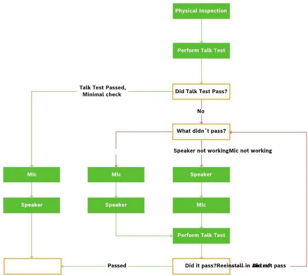
flowchart
graph TD
    A["Physical Inspection"] --> B["Perform Talk Test"]
    B --> C["Did Talk Test Pass?"]
    C -->|No| D["What didn't pass?"]
    C -->|Talk Test Passed, Minimal check| E["Mic"]
    D --> F["Speaker not working"]
    D --> G["Speaker not working"]
    F --> H["Speaker"]
    G --> I["Speaker"]
    H --> J["Micro"]
    I --> K["Micro"]
    J --> L["Micro"]
    K --> M["Micro"]
    L --> N["Micro"]
    M --> O["Micro"]
    N --> P["Micro"]
    O --> Q["Micro"]
    P --> R["Micro"]
    Q --> S["Micro"]
    R --> T["Micro"]
    S --> U["Micro"]
    T --> V["Micro"]
    U --> W["Micro"]
    V --> X["Micro"]
    W --> Y["Micro"]
    X --> Z["Micro"]
    Y --> AA["Micro"]
    Z --> AB["Micro"]
    AA --> AC["Micro"]
    AB --> AD["Micro"]
    AC --> AE["Micro"]
    AD --> AF["Micro"]
    AE --> AG["Micro"]
    AF --> AH["Micro"]
    AG --> AI["Micro"]
    AH --> AJ["Micro"]
    AI --> AK["Micro"]
    AJ --> AL["Micro"]
    AK --> AM["Micro"]
    AL --> AN["Micro"]
    AM --> AO["Micro"]
    AN --> AP["Micro"]
    AO --> AQ["Micro"]
    AP --> AR["Micro"]
    AQ --> AS["Micro"]
    AR --> AT["Micro"]
    AS --> AU["Micro"]
    AT --> AV["Micro"]
    AU --> AW["Micro"]
    AV --> AX["Micro"]
    AW --> AY["Micro"]
Review all plastic parts for cracks or breaks
To review plastic parts, do the following:
- Note any parts which need to be replaced
Review all cables for obvious signs of damage to the insulating materials
To review cables, do the following:
- Look for any cables that have been pulled out of the housings.
- Look for any cables with unnatural or unusual bends or breaks.
- Note any cable assemblies that need to be replaced.
Review user replaceable items
To review user replaceable items, do the following:
- Check ear cushions.
- Check headband pads.
- Check microphone windscreen.
- Check clothing clips.
- Note any replaceable items that need to be replaced.
Talk Test
When performing a talk test, things to be aware of:
- Note any unusual or unexpected noises, static, and oscillations.
- Note any distorted audio.
- Verify sound is heard in both ears.
5.3 Microphone troubleshooting

flowchart
graph TD
    A["Does Mic Pass theTalk Test"] -->|No| B["Validate Power Source"]
    A -->|Yes| C["Test Sensitivity and THD"]
    B --> D["Visual Inspection of all internal wires"]
    D --> E["Are wires damaged"]
    E -->|Yes| F["Replace the broken wires"]
    E -->|No| G["Is Mic circuitry validated"]
    G -->|Yes| H["Replace Microphone Assembly"]
    G -->|No| I["Replace PCBA"]
    C --> J["Does the Mic Meet Sensitivity and THD Specifications"]
    J -->|No| K["Adjust Microphone Sensitivity"]
    J -->|Yes| L["Replace Microphone or Circuit"]
    K --> M["Microphone Test Complete"]
    L --> N["Replace Cord"]
    M --> O["Validate continuity from plug to PCBA"]
    N --> P["Is there power to the PCBA"]
    O --> Q["Replace Cord"]
    P --> R["Replace Cord"]
    Q --> S["Replace Cord"]
5.3.1 Validate continuity from plug to boom-side PCBA
To validate continuity from the plug to the boom-side PCBA, do the following:
- Using an Ohmmeter, place one probe on the ring terminal of the PJ-068 plug or pin 3 of the XLR plug.
- Place the other probe at J1 on the PCBA.
- Record the measurement.
- Using an Ohmmeter, place one probe on the sleeve terminal of the PJ-068 plug or pin 4 of the XLR plug.
- Place the other probe at J2 on the PCBA.
- Record the measurement.
If the reading is approximately zero, continuity is good.
If any other reading is seen, the continuity is bad. Replace the cable.
5.3.2 Validate mic circuitry
To validate the mic PCBA, do the following:
- Construct a test circuit.
- Connect the test circuit to the microphone.
- Apply a signal/excitation to the microphone.
If audio signal is detected, the board is validated.
If audio signal is not detected, the board should be replaced.
5.3.3 Microphone/amplifier sensitivity test

Notice!
This headset was designed, tested, and approved to FAA TSO C139a. The TSO requires the headset meet the minimum performance specifications as defined in RTCA DO-214a. This document and specifications listed here reference the test procedures and equipment used as defined in these standards. Refer to the standard for details on how to perform individual tests.
To test sensitivity of the microphone, do the following:
- Calibrate an artificial mouth.
- Using the test circuit from the mic validation and TSO procedures, measure the output of the headset microphone with a true RMS AC voltmeter.
5.3.4 Microphone sensitivity adjustment
The microphone gain has been factory-adjusted to the nominal level required for normal radio operation. Microphone sensitivity adjusts by turning the gain adjustment control.
To adjust the microphone, do the following:
- Rotate the boom mic clockwise until the microphone gain adjustment access hole is aligned and open.
- Insert a 2mm x 0.5mm flat-bladed screwdriver into the gain adjustment access hole.

Notice!
If the gain adjustment access hole is properly aligned, the screwdriver can be inserted approximately 12 -inch into the hole. If not properly aligned, the screwdriver only inserts approximately 1/8-inch into the hole.
- Turn the gain adjustment potentiometer clockwise to increase the gain. OR
Turn the gain adjustment potentiometer counterclockwise to decrease the gain.
5.3.5 Microphone total harmonic distortion (THD) test
To test the microphone THD, do the following:
- Calibrate the sound pressure to be 114 dB SPL at 6 mm from an artificial mouth.
- Measure the THD of the microphone placed at that location using the same test circuit. It meets the TSO spec when THD is less than 5% from 350 Hz to 6000 Hz.
- Increase the sound pressure input from 114 dB SPL to 120 dB SPL at frequency response peak must yield an output increase of at least 5 dB.
5.4 Speaker troubleshooting

flowchart
graph TD
    A["Do the Speakers Pass the Talk Test"] --> B{Did Failure occur in both speakers?}
    B -->|No| C["Which Speaker Fact?"]
    B -->|Yes| D["Physically Impact the overhead cable"]
    C --> E{Are the speaker wire in good condition?}
    E -->|No| F["Replace the Beam Ligt Speaker Wire"]
    E -->|Yes| G{Check the soldier points at the speaker and at the board?}
    G -->|No| H{Are the soldier points in good condition?}
    H -->|Yes| I["Regulator the speaker worst"]
    H -->|No| J{Is the resistance good?}
    J -->|No| K["Replace the Speaker"]
    J -->|Yes| L{Test the PCBA}
    K --> M{Did the PCBA Pass?}
    M -->|No| N["Replace the PCBA"]
    M -->|Yes| O["Test Significantly"]

    C --> P["Physically Impact the overhead cable"]
    P --> Q{Is the overhead cable is good condition?}
    Q -->|No| R["Replace the cable"]
    Q -->|Yes| S{Are the speaker wire is good condition?}
    S -->|No| T["Replace the Beam rate Speaker Wire"]
    S -->|Yes| U{Check the soldier points at the speaker and at the board?}
    U -->|No| V["Replace the Beam side PCBA"]
    U -->|Yes| W{Are the soldier points in good condition?}
    W -->|No| X["Replace the speaker wire"]
    W -->|Yes| Y{Are the soldier points in good condition?}
    Y -->|No| Z["Replace the speaker wire"]
    Y -->|Yes| AA{Check the soldier points at the speaker and at the board?}
    AA -->|No| AB["Replace the speaker wire"]
    AA -->|Yes| AC{Are the soldier points in good condition?}
    AC -->|No| AD["Replace the speaker wire"]
    AC -->|Yes| AE{Are the soldier points in good condition?}
    AE -->|No| AF["Replace the speaker wire"]
    AE -->|Yes| AG{Measure Revolvement of Speaker}
    AG --> AH{Is the resistance good?}
    AH -->|No| AI["Replace the Speaker"]
    AH -->|Yes| AJ["Text the PCBA"]
    AH -->|Yes| AK["Did the PCBA Pass?"]
    AK --> AL{Did the PCBA Pass?}
    AL -->|No| AM["Replace the PCBA"]
    AL -->|Yes| AN["Replace the PCBA"]

    C --> AO["Physically Impact the other cable"]
    AO --> AP{Is the main cable is good condition?}
    AP -->|No| AQ["Replace the main cable"]
    AP -->|Yes| AR["Check soldier lines on beam side PCBA"]
    AQ --> AS{Are the soldier points in good condition?}
    AS -->|No| AT["Replace the rod line to the PCBA"]
    AS -->|Yes| AU["Test the Beam side PCBA"]
    AT --> AV{Did it Pass?}
    AV -->|No| AW["Replace the PCBA"]
    AV -->|Yes| AX["Remove constitutory from plug to PCBA"]
    AW --> AY{Is the continuity good?}
    AX --> AZ["Replace the Cable"]
    AX --> BA{Is the PCBA working?}
    BA --> BB{Prepare the PCBA}
    BA --> BC["Replace the operator"]

    AP --> BD{Does the speaker work?}
    BD -->|No| BE["middle the PCBA"]
    BD -->|Yes| BF{The speakers are wind in series, meaning when one speaker safe, both fast. Resistance verification on both speakers must be done.}
5.4.1 Speaker sensitivity and frequency response verification

Notice!
This headset was designed, tested, and approved to FAA TSO C139a. The TSO requires the headset meet the minimum performance specifications as defined in RTCA DO-214a. This document and specifications listed here reference the test procedures and equipment used as defined in these standards. Refer to the standard for details on how to perform individual tests.
All models tested, unless noted otherwise.
| Transducer Type: Dynamic | |
| Transducer: 600Ω | |
| Impedance (at the earphone plug) Must meet | standards outlined in the specifications table in either the technical manual or the technical data sheet. |
| Sensitivity: | |
| Frequency Response |
5.4.2 Validate continuity from plug to boom-side PCBA
To validate continuity from the plug to the boom-side PCBA, do the following:
- Using an Ohmmeter, place one probe on the tip terminal of the PJ-055 plug or pin 1 of the XLR plug.
- Place the other probe at J7 on the PCBA.
- Record the measurement.
- Using an Ohmmeter, place one probe on the sleeve terminal of the PJ-055 plug or pin 2 of the XLR plug.
- Place the other probe at J8 on the PCBA.
- Record the measurement.
- If the reading is approximately zero, continuity is good.
- If any other reading is seen, the continuity is bad. Replace the cable.
5.4.3 Validate the PCBA
To validate the PCBA, do the following:
- On the boom side PCBA, supply a 1 kHz sine wave, 1Vrms signal between J7 and J8.
- If a signal is heard from both speakers, the boards, speakers and wiring are good. If no sound is heard from one or both speakers, a speaker or the wiring is bad. Determine if a speaker needs to be replaced or the wires need re-soldering.
- If no sound is heard from one or both speakers after the above step, one or both boards are not good and should be replaced.
5.5 Cleaning the headset and connectors

Notice!
Do not allow alcohol or any liquid to touch the speaker or microphone element directly.
To clean the headset, do the following:
Clean the plastic and metal headset parts with a mild detergent with water and a soft towel or isopropyl alcohol wipes.

Notice!
Do not soak or allow liquid to puddle on the unit.
5.6 Cleaning the ear cushions and headband pads

Notice!
Do not soak cushions or pads.
To clean the ear cushions and headband pads, do the following:
Gently wipe the ear cushions and headband pad thoroughly with a soft towel dampened with water or isopropyl alcohol.
5.7 Replacing ear cushions and headband pads
To ensure optimal product performance, it is recommended you replace ear cushions and headband pads periodically (every six months, or sooner if needed).
For more information, see Recommended maintenance schedule, page 11.
For detailed instructions on replacing the ear cushions, see Ear cushion replacement, page 19.
For detailed instructions on replacing the headband pads, see Headband pad holder and headpad replacement, page 20.
5.8 Installing and replacing the hygienic covers

Notice!
Two hygienic covers are included with the headset. Extra hygienic covers can be purchased separately.
To replace the hygienic covers, do the following:
- Grasp the edge of the hygienic cover where it folds into the slot on the ear cup.
- Gently pull the hygienic cover up and away from the ear cup.
- Carefully work the new cover (starting at the top of the ear cup) around the ear cup until it is in place.
5.9 Replacing the windscreen
The foam windscreen, once removed from the microphone, can be cleaned using low pressure air to blow contaminates off from the exterior. If low-pressure air does not provide effective results, the windscreen should be replaced.

Notice!
Do not use any liquid on the foam windscreen.
To remove the windscreen, do the following:

Notice!
Do not use excessive force when removing the windscreen. This may result in damage to the microphone.
- Take care to pull the sides of the windscreen away from the mic pre-filter wings before removing the windscreen to avoid damaging the windscreen or microphone.

- Grasp the microphone windscreen and gently pull away from the microphone.
To replace the windscreen, do the following:
▶ Slide the new windscreen over the microphone.
5.10 Headset storage
To store the headset, do the following:
- Move the boom mic above the headband.
- Coil the cord into a loop.
- Place the coiled cord and headset in the carrying case.
6 Disassembly
The following procedure describes the complete disassembly of the AIRMAN 7P headset.

Notice!
The removal process requires the following steps to be followed in the order described. Assembly is the reversal of the disassembly procedure. Please take care when disassembling to note details that may be required in the reassembly process, such as the locations of disconnected wires.
When soldering, be careful not to touch the plastic housing of the headset/headphone with the soldering iron.

Notice!
Only disassemble parts that are necessary for the repair.
6.1 Ear cushion replacement
To ensure optimal product performance, replace cushions and pads periodically. For more information, see Recommended maintenance schedule, page 11.
To replace the ear cushions, do the following:
- Remove the hygiene covers, if installed.
- Grasp the edge of the ear cushion where it folds into the slot on the ear cup.
- Gently pull the ear cushion up and away from the ear cup.
- To install the replacement ear cushion, starting at the top of the ear cup (1), carefully work the cushion around the cup (2) until it is in place (3).
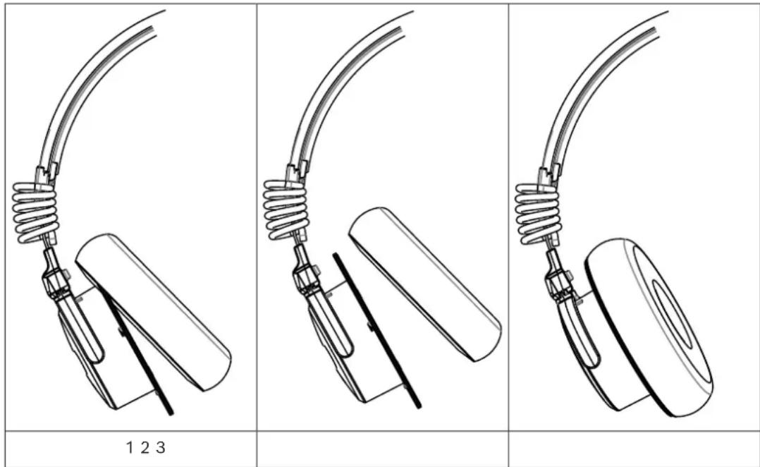
- Verify the replacement is fully seated by visually inspecting around the cushion before use.
6.2 Headband pad holder and headpad replacement
There are two styles of headband pads, a low profile headpad and a thicker cushioned headpad. The thicker headpad comes installed on the headset.
To replace the low profile headpad holder and headpad, do the following:
- At one end of the headpad holder, carefully pry the holder from the headband cover.

Carefully twisting slightly on the headpad holder can help remove the piece easier.
- With the new headpad holder, hook one side of the headpad holder over the headband cover.
- Snap the other side of the headpad holder in place. Be sure the headpad holder edge is over the headband cover.
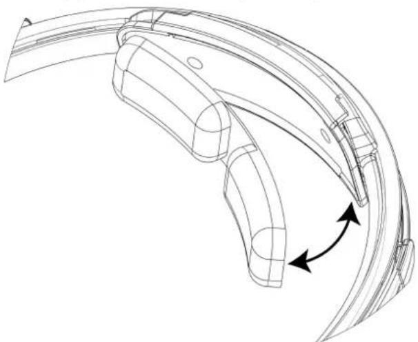
To replace the low profile headband pad, do the following:
- Grasp the edge of the headband pad.
- Gently pull the headband pad away from the headpad holder.
- Remove the paper from the sticky side of the new headband pad.
- Align the headband pad with the recessed area on the headpad holder.
- Firmly press the headband pad into place.
natural_image
Technical line drawing of a curved mechanical component with directional arrows indicating motion (no text or symbols)To replace the thicker cushioned headband pad, do the following:
- Grasp the edge of the headband pad.

natural_image
Line drawing of a headset with attached cable and earplugs, no text or symbols present- Gently pull the headband pad away from the headpad holder.
- Align the new headband pad with the Velcro on headpad holder.

natural_image
Line drawing of a dual-hHead耳机 with attached microphone and headband (no text or symbols)- Firmly press the new headband pad into place.
6.3 Remove the mic prefilter
To remove the prefilter, do the following:
▶ Carefully pry the prefilter from the mic.

natural_image
Pure mechanical component diagram without any text, numbers, or symbols6.4 Remove the yoke assembly from the headband assembly
To remove the yoke assembly from the headband assembly, do the following:
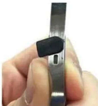
- Use a fingernail to lift the bottom edge of the black plastic spacer.
- Swivel the black plastic spacer to the side and remove it from the assembly.
natural_image
Close-up of a hand holding a metallic tool or device with a black clip, no visible text or symbols.- Slide the yoke assembly off of the headband.
6.5 Boom side disassembly
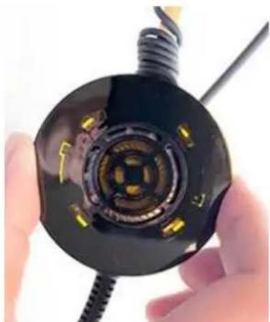
To remove the speaker assembly and sleeve, do the following:
- At the same time, push the two retaining cams located in the speaker assembly out of the way.
- Rotate the speaker faceplate approximately 15^ clockwise.
natural_image
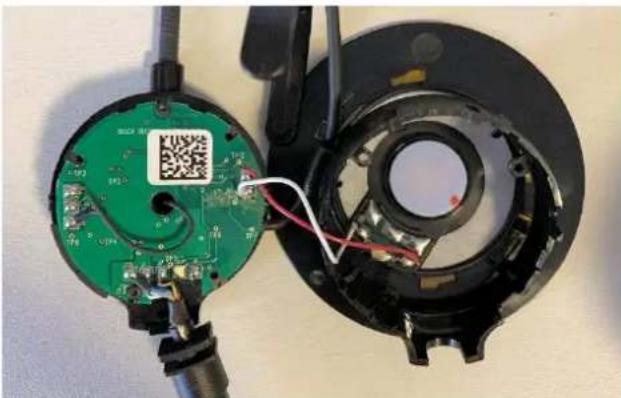
Close-up of a hand holding a black circular device with internal components, no visible text or symbols- Using a T-5 screwdriver, remove three screws (as shown).

natural_image
Close-up of a mechanical device with green circuit board and black circular components, no visible text or symbols- Remove the housing and the yoke/glider assembly.
natural_image
Close-up of a green circuit board with a QR code inserted, partially exposed to a black circular device (no text or symbols visible)- Using a T-5 screwdriver, remove two screws (as shown).

natural_image
Close-up of a green electronic circuit board with visible components and a QR code on top (no readable text or symbols beyond labels)-
Remove the PCBA.
-
Using a soldering iron, carefully disconnect the wires from the speaker and overhead cord and boom mic assembly, as needed.

natural_image
Close-up of a green printed circuit board being held by black plastic components, no visible text or symbols
Notice!
Take care to avoid touching the plastic housing with the soldering iron.
6.6 Non-boom side disassembly
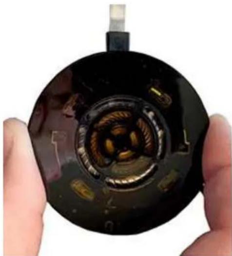
To remove the speaker assembly and sleeve, do the following:
- Pushing the two retaining cams simultaneously on the speaker assembly, rotate the speaker faceplate approximately 15^ clockwise.
natural_image
Close-up of hands holding a circular mechanical component with internal components (no visible text or symbols)
Notice!
To avoid pulling the wires from the board, do not pull the speaker assembly more than 12mm from the ear shell.
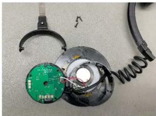
- Using a T-5 screwdriver, remove three screws (as shown).

natural_image
Disassembled electronic components including a green circuit board and black circular base with coiled spring (no text or symbols visible)- Remove the housing and the yoke/glider assembly.
natural_image
Disassembled electronic component with green circuit board and coiled spring, no visible text or symbols- Using a T-5 screwdriver, remove two screws (as shown).

natural_image
Disassembled electronic device with green circuit board and exposed wiring, partially enclosed in a black plastic housing (no text or symbols visible)- Remove the PCBA.
- Using a soldering iron, carefully disconnect the wires from the speaker and overhead cord, as needed.

natural_image
Close-up of an open electronic device with exposed circuit board and wires, next to a green printed circuit board (no visible text or symbols)7 Assembly
7.1 Boom side assembly
To assemble the boom side assembly, do the following:
- Solder the overhead cord to the PCBA.
| J10 Red |  | |
| J11 Shield |
- Solder the cable assembly to the PCBA.
- Thread the boom mic wires through the center hole.
- Using the two shorter screws, attach the PCBA to the boom mic assembly.

natural_image
Close-up of a green printed circuit board with visible components and a QR code on top (no readable text or symbols beyond labels)- Solder the boom mic wires to the PCBA.

Notice!
Use shield as an anchor point so there is slack on smaller wires.
| J4 Red | |
| J5 Green | |
| J6 Shield |
- Solder the main cord to the PCBA
| AIRMAN7P-0210 AIRMAN7P-0211 | ||
| J7 Yellow | ||
| J8 Black | ||
| J2 Blue Drain wire + blue | ||
| J1 White | ||
| J13 No Connection | ||
- Route the speaker wires through the housing and solder to the PCBA.
| J9 Red | |
| J12 White |
- Route the overhead cord and the headset cord through the corresponding grooves provided on the boom.


Notice!
Take care to verify the orientation of the yoke, because it does not rotate 360°.

Notice!
The side with the deep grooves goes toward the speaker.
- Place the housing on the boom mic assembly.
- Make sure the overhead cord is in the correct slot and the jacket is fully inside the housing. Also, make sure the headset cord is properly located in the housing.

natural_image
Close-up of a mechanical component with wires and wiring, no visible text or symbols- Using a T-5 screwdriver, replace the three screws (as shown) to attach the yoke and housing to the PCBA.
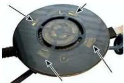
- Position the overhead cord in the guide, and then align the knob of the faceplate toward the bottom.
- Align the four tabs on the faceplate, and then rotate counterclockwise to lock.

Notice!
Verify all four tabs engage and retaining tabs are in the groove.
natural_image
Close-up of a circular mechanical component with arrows pointing to features, no visible text or symbols.
natural_image
Close-up of a black electric vehicle charging plug with cable and ear (no visible text or symbols)- Carefully wind the overhead cord around the glider.
7.2 Non-boom side assembly
To assemble the non-boom side assembly, do the following:
| J10 Red | 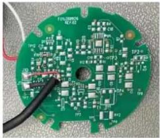 | |
| J11 Shield |
- Using the two shorter screws, attach the PCBA to the cover.

natural_image
Close-up of a circular mechanical component with labeled parts (1 and 2), no readable text or symbols beyond labels
1 Alignment posts for PCBA screw
2 Path for overhead cord

Notice!
Align the red wire with the polarity dot on the speaker (as shown)
| J9 Red | ||
| J12 White |
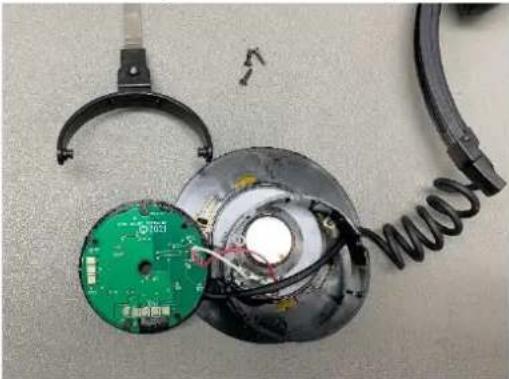
- Route the speaker wires through the housing and solder to the PCBA.
natural_image
Disassembled electronic components including a green circuit board, black clamping device, and coiled spring on a workbench (no text or symbols visible)- Place yoke on the housing.

Notice!
Take care to verify the orientation of the yoke, because it does not rotate 360°.
- Place the cover on the housing.

natural_image
Close-up of a black electronic device with a speaker and cable, showing mechanical components and a small circular component (no visible text or symbols)- Using a T-5 screwdriver, replace the three screws (as shown) to attach the yoke and housing to the PCBA.

natural_image
Disassembled electronic components including a green circuit board, black circular base with coiled spring, and exposed wiring (no text or symbols visible)-
Position the overhead cord in the retaining clip and align the knob of the faceplate toward the bottom.
-
Align the four tabs on the faceplate, and then rotate counterclockwise to lock.

Notice!
Verify all four tabs engage and retaining tabs are in the groove.

natural_image
Close-up of a mechanical component with arrows pointing to features, no visible text or symbols
natural_image
Close-up of a hand holding a black TEL brand camera lens with a small arrow pointing to the lens (no text or symbols visible)- Carefully wind the overhead cord around the glider.
7.3 Attach the prefilter
To attach the prefilter, do the following
▶ Carefully clip the prefilter to the mic.
7.4 Replace the yoke assembly on the headband assembly
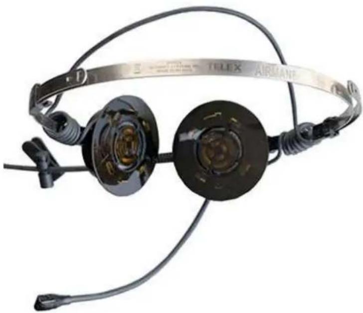
To replace the yoke assembly on the headband assembly, do the following:
- Slide the yoke assembly onto the headband.
natural_image
Close-up of a black TELIX AIRMAN2 headset with exposed wiring and earpluses (no text or symbols visible on the device itself)- Place the glider stop in the appropriate hole on the glider.
- Swivel the spacer in line with the glider.

natural_image
Close-up of a hand holding a metallic object with a black clip, no visible text or symbols- Click the bottom edge of the black plastic spacer into the retaining hole.
7.5 Reinstall the headband cover
To reinstall the headband cover, do the following:
- Take care to verify the overhead cord lays between the guides.
- Ensure the cover fully encloses around the headband at both sides.

natural_image
Close-up of a black flexible cable with a coiled spring, no text or symbols visible8 Wiring diagrams and connectors
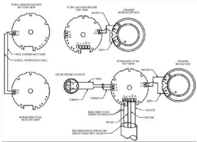
AIRMAN 7P Series headsets are available with multiple connector styles depending on the application of use. All models utilize custom cables developed specifically for cockpit use. All connection points implement strain and bend relief features to provide long-term durability. Shielded wire throughout the headset protects against RFI (Radio Frequency Interference) and EMI (Electromagnetic Interference).
PJ-068 / PJ-055 Connector Diagram for Airman7+ · 0210

natural_image
Technical line drawing of a mechanical component with two labeled parts (1 and 2), showing internal structure and assembly details (no text or symbols beyond labels)Figure 8.1: PJ Connector
| 1 P | J-068 or equivalent Description | |
| Tip Not Used | ||
| Ring Mic Signal (Power +) | ||
| Sleeve Mic GND (Power -) |
| 2 P | J-055 or equivalent Description | |
| Tip Headphone Signal | ||
| Sleeve Headphone GND |
5-Pin XLR Connector Diagram for Airman7+ - 0211

natural_image
Technical line drawing of a connector with threaded end and circular socket (no text or symbols)Figure 8.2: Airman 5-pin XLR
| Pin Description Color | ||
| 1 Headphone Signal Yellow | ||
| 2 Headphone GND Black | ||
| 3 Mic Power and Signal | White | |
| 4 Mic GND Blue/Drain or Shield | ||
| 5 Power Not used | ||
F01U398270, AIRMAN 7+ 2PJ, HEADSET WIRING DIAGRAM

F01U398271, AIRMAN 7+ XLR, HEADSET WIRING DIAGRAM

natural_image
Front view of a white aircraft fuselage with visible structural details and window grilles, mounted on a concrete wall (no text or symbols)Bosch Security Systems, LLC
130 Perinton Parkway
Fairport, NY 14450
USA
www.telex.com
© Bosch Security Systems, LLC, 2024
EU importer:

- Record of Revisions
- Purpose of manual
- Technical support
- Parts ordering
- Repairs
- Safety Precautions
- Caution!
- Notice!
- Introduction
- Reference view
- Parts list and exploded view
- Exploded view
- Parts list
- Maintenance
- Recommended maintenance schedule
- Basic inspection
- Basic Inspection
- Review all plastic parts for cracks or breaks
- Review all cables for obvious signs of damage to the insulating materials
- Review user replaceable items
- Talk Test
- Microphone troubleshooting
- Validate continuity from plug to boom-side PCBA
- Validate mic circuitry
- Microphone/amplifier sensitivity test
- Microphone sensitivity adjustment
- Microphone total harmonic distortion (THD) test
- Speaker troubleshooting
- Speaker sensitivity and frequency response verification
- Validate continuity from plug to boom-side PCBA
- Validate the PCBA
- Cleaning the headset and connectors
- Cleaning the ear cushions and headband pads
- Replacing ear cushions and headband pads
- Installing and replacing the hygienic covers
- Replacing the windscreen
- Headset storage
- Disassembly
- Ear cushion replacement
- Headband pad holder and headpad replacement
- Remove the mic prefilter
- Remove the yoke assembly from the headband assembly
- Boom side disassembly
- Non-boom side disassembly
- Assembly
- Boom side assembly
- Non-boom side assembly
- Attach the prefilter
- Replace the yoke assembly on the headband assembly
- Reinstall the headband cover
- Wiring diagrams and connectors
Brand : Telex
Model : AIRMAN 7P
Category : Headphones