
Airman 8 - Headphones Telex - Free user manual and instructions
Find the device manual for free Airman 8 Telex in PDF.


| Product Type | Aviation Headset |
| Brand | Telex |
| Model | Airman 8 |
| Connectivity | Wired, dual plug (PJ-068 and PJ-055) |
| Noise Cancellation | Active Noise Reduction (ANR) |
| Microphone | Noise-canceling electret microphone |
| Microphone Type | M-87 or M-102, adjustable |
| Speaker Impedance | 150 Ω per ear |
| Frequency Response | 300 Hz – 4 kHz (voice band) |
| Power Source | Aircraft power (helo or fixed wing) or 2 AA batteries (for ANR) |
| Battery Life (ANR) | Up to 40 hours with alkaline batteries |
| Dimensions (HxWxD) | 190 x 180 x 90 mm |
| Weight | 340 g (without batteries) |
| Headband | Adjustable, spring steel with foam padding |
| Earcups | Full ear enclosure, leatherette cushions |
| Environmental Sealing | Not specified (likely resistant to moisture) |
| Operating Temperature | -20 °C to 50 °C |
| Storage Temperature | -40 °C to 70 °C |
| Cable Length | 1.8 m (coiled, extends to 3 m) |
| Controls | Volume control on earcup, ANR on/off switch |
| Certifications | TSO C57a, C58a, C139 |
| Cleaning Instructions | Wipe with damp cloth; do not use solvents |
| Storage | Store in dry place, avoid extreme temperatures |
| Spare Parts | Earcushions, microphone, batteries, cable (replaceable) |
| Repairability | Repairable by authorized service centers; typical lifespan 10+ years |
Frequently Asked Questions - Airman 8 Telex
User questions about Airman 8 Telex
0 question about this device. Answer the ones you know or ask your own.
Ask a new question about this device
Download the instructions for your Headphones in PDF format for free! Find your manual Airman 8 - Telex and take your electronic device back in hand. On this page are published all the documents necessary for the use of your device. Airman 8 by Telex.
USER MANUAL Airman 8 Telex
Maintenance & Overhaul Manual for Airman 8 Headset & Headphone

natural_image
Black hardhead with earplugs and microphone, isolated on white background (no text or symbols)Record of Revisions
| Rev No. | Revision Date Change Description | |
| 01 08/2018 | Created | |
| 02 01/2019 | Add CTNs to Sec2.4 Parts List | |
Purpose of Manual
This manual contains information for the overhaul and servicing of the Airman 8 headsets.
Technical Support
A liaison between the customer and factory is provided by the Bosch Product Support Department. Consultation and assistance on technical problems, part information, and availability of local and factory repair facilities is available. When writing, include all information concerning problem and mail to:
Bosch Communications, Inc.
8601 Cornhusker Hwy
Lincoln, NE 68507 U.S.A.
Attn: Aircraft Product Support Mgr.
Telephone: 877.863.4168
Parts Ordering
Replacement parts may be ordered from our parts department. When ordering, please include the following information:
- Model Number
- Part Description
- Part Number
- Quantity
Mail To:
Bosch Communications, Inc.
8601 Cornhusker Hwy
Lincoln, NE 68507 U.S.A.
Attn: Parts Department
Telephone: 800.553.5992
Fax: 402.467.3279
E-mail: repair.lincoln@us.bosch.com
Repairs
In order to maintain the FAA certification, all repairs to the headset must be made only by persons authorized under Part 43 of the Federal Aviation Agency regulations. Bosch offers full support, repair, and recertification.
Safety Precautions

CAUTION:
This information is for use by qualified personnel only. Have all service work and repairs performed by a trained technician.
• Unauthorized changes, modifications, or alterations to the product are prohibited.

CAUTION:
An ESD protection method should be applied before proceeding with any Mechanical/Electrical instructions

CAUTION:
Use of any replacement part, which does not have the same specifications, may cause malfunctioning of the device and could make the product not air worthy!

NOTE: Any material to be disposed of should be done according to local environmental laws.
Table
of
Contents
CHAPTER 1
Introduction & Specifications.... 7
1.1 Introduction....7
1.1.1 General Description ...... 7
1.1.2 Models Covered 7
1.2 Specifications 7
1.2.1 For current specifications, see: 7
1.3 Reference View 8
CHAPTER 2
Parts List and Disassembly/Assembly.... 9
2.1 Parts List.... 9
2.2 Reference Views ...... 10
2.3 Disassembly/Assembly 11
2.3.1 Disassembly 11
2.3.1.1 Remove the headband cover clips (if present).... 11
2.3.1.2 Replace Cushions and Windscreen 12
2.3.1.3 Remove the mic prefilter.... 14
2.3.1.4 Remove the Yoke Assembly from the Headband Assembly 14
2.3.1.5 Boom Side Disassembly 15
2.3.1.6 Non-Boom Side Disassembly 17
2.3.2 Assembly 20
2.3.2.1 Boom Side Assembly 20
2.3.2.2 Non-Boom Side Assembly.... 25
2.3.2.3 Attach the mic prefilter 29
2.3.2.4 Reinstall the headband cover 29
2.3.2.5 Replace the Yoke Assembly from the Headband Assembly 30
2.3.2.6 Replace the headband cover clips (if present).... 31
2.3.2.7 Replace Cushions and Windscreen 32
CHAPTER 3
Maintenance.... 35
3.1 Troubleshoot and Maintenance 35
3.1.1 Recommended Maintenance Schedule 35
3.1.2 Physical Inspection.... 37
3.1.2.1 Review all plastic parts for cracks or breaks.... 37
3.1.2.2 Review all cables for obvious signs of damage to the insulting materials...... 37
3.1.2.3 Review user replaceable items 37
3.1.3 Talk Test.... 37
3.1.4 Microphone Troubleshooting and Workflow.... 39
6 Airman 8
3.1.4.1 Validate Continuity From Plug to PCBA 39
3.1.4.2 Validate Mic PCBA 39
3.1.4.3 Microphone/Amplifier Sensitivity Check 39
3.1.4.4 Microphone Sensitivity Adjustment 40
3.1.5 Speaker Troubleshooting and Workflow 41
3.1.5.1 Speaker Sensitivity and Frequency Response Verification 42
3.1.5.2 Measure the Resistance (Plug to PCBA) 42
3.1.5.3 Validate the Boom Side PCBA 42
3.1.5.4 Validate the Non-boom Side PCBA 42
3.1.6 ANR Troubleshooting and Workflow 43
3.1.6.1 Cleaning the Headset and Connectors 45
3.1.6.2 Cleaning the Ear Cushions and Headband Pads 45
3.1.6.3 Replacing Ear Cushions and Headband Pads 45
3.1.6.4 Installing and Replacing the Hygienic Covers 45
3.1.6.5 Replacing the Windscreen 46
3.1.6.6 Headset Storage 46
CHAPTER 4
Wiring / Connectors.... 49
4.1 Wiring Diagrams.... 49
4.1.1 Wiring Diagram Airman8-2010 and Airman8-0211 49
4.2 Connectors 50
4.2.1 PJ-068/PJ055 Connector Diagram for Airman8-0210.... 50
4.2.2 XLR Connector Diagram for Airman8-0211....51
1.1 Introduction
1.1.1 General Description
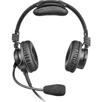
The Telex Airman 8 is a lightweight noise-reducing headset designed specifically for optimizing pilot communications in commercial and business turbine aircraft. Building on the tradition of the Airman 850, the Airman 8 has improved durability, intelligibility, and comfort. The Airman 8 is among the lightest ANR (Active Noise Reduction) headset on the market and the only FAA approved ANR headset to utilize Telex's proprietary battery-free, noise-reduction system.
1.1.2 Models Covered
TABLE 1. AIRMAN 8 Models and Connector/Wiring
| MODEL NUMBER | DESCRIPTION |
| AIRMAN8-0210 D | DOUBLE SIDE ANR HEADSET 2PJ 600 OHM |
| AIRMAN8-0211 D | DOUBLE SIDE ANR HEADSET XLR5 600 OHM |
1.2 Specifications
IMPORTANT: This document uses FAA standard HATS (Head and Torso Setup) for specification measurement testing.
1.2.1 For current specifications, see:
• Airman 8 Technical Manual (F01U307704) located on the website.
- Airm an 8 Technical Data Sheet (F01U307701) located on the website.
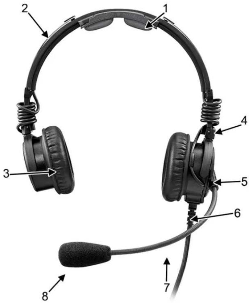
1.3 Reference View
- Headband Holder and Pad
- Headset Slider
- Ear Cushion
- Ear Cup Rotator
- Boom Rotator
- Cord with Strain Relief
- Boom
- Microphone/Windscreen
Parts List and Disassembly/Assembly
2.1 Parts List
| Item CTN PART NO. DESCRIPTION MODEL | |||||
| -0210 | -0211 | ||||
| 1^a,b | AIRMAN7-0905 F.01 | U.313.420 | CARRYING CASE 1 1 | ||
| S-F01U342107 F.01 | U.342.107 | ||||
| 2^b | AIRMAN7-0900 F.01 | U.313.415 WINDSCREEN (2PCS) | 1 | 1 | |
| S-F01U327249 F.01 | U.327.249 WINDSCREEN (SINGLE) | ||||
| 3^b | AIRMAN7-0906 F.01 | U.313.421 | HEAD PAD 1 1 | ||
| S-F01U342089 F.01 | U.342.089 | ||||
| 4^a,b | AIRMAN8-0901 F.01 | U.313.996 SANITARY COVER, AIRMAN 8 (10PCS) | |||
| S-F01U342106 F.01 | U.342.106 SANITARY COVER, AIRMAN 8 (2PCS) | ||||
| 5^b | AIRMAN8-0900 F.01 | U.313.418 | EAR CUSHION, AIRMAN 8 (2pcs) 1 1 | ||
| S-F01U342110 F.01 | U.342.110 | ||||
| 6^a,b | AIRMAN7-0904 F.01 | U.313.419 | CLOTHING CLIP | 1 1 | |
| S-F01U342113 F.01 | U.342.113 | ||||
| 7^b,c | AIRMAN7.0908 | F.01U.344.857 | MIC PREFILTER | 1 1 | |
| S-F01U346184 F.01 | U.346.184 | ||||
| 8^a | 590404360 | F.01U.109.816 | SCREW, PT, PAN HEAD, K15 X 6MM, BLK ZINC | 6 | 6 |
| 9^a | 54857101 | F.01U.150.106 | WIRE 28 AWG 212 WHITE | 2 | 2 |
| 10^a | 54857103 | F.01U.150.110 | WIRE 28 AWG RED | 2 | 2 |
| 11 | S-F01U342083 | F.01U.342.083 | CORD UNIT, PJ Y-BLOCK | 1 | 1 |
| 12 | S-F01U342084 | F.01U.342.084 | EAR SHELL, BOOM SIDE, AIRMAN 8 | 1 | 1 |
| 13 | S-F01U342085 | F.01U.342.085 | EAR SHELL, NON BOOM SIDE, AIRMAN 8 | 1 | 1 |
| 14 | S-F01U342086 | F.01U.342.086 | COVER, NON BOOM SIDE, AIRMAN 8 | 1 | 1 |
| 15 | S-F01U342087 | F.01U.342.087 | SWITCH ACTUATOR, AIRMAN 8 | 1 | 1 |
| 16 | S-F01U342088 | F.01U.342.088 | GLIDER STOP (2PCS) | 1 | 1 |
| 17 | S-F01U342090 | F.01U.342.090 | HEADBAND COVER | 1 | 1 |
| 18 | S-F01U342094 | F.01U.342.094 | PCBA, NON BOOM SIDE, AIRMAN 8 | 1 | 1 |
| 19 | S-F01U342096 | F.01U.342.096 | PCBA, BOOM SIDE, AIRMAN 8 | 1 | 1 |
| 20 | S-F01U342097 | F.01U.342.097 | LABEL, TELEX | 1 | 1 |
| 21 | S-F01U344915 | F.01U.344.915 | CORD UNIT, XLR, 5M | 1 | 1 |
| 22^d | S-F01U344917 F.01 | U.344.917 | SPEAKER ASSY, AIRMAN 8 (including faceplate) | 1 | 1 |
| 23 | S-F01U344918 | F.01U.344.918 | OVER HEAD CABLE | 1 | 1 |
| 24 | S-F01U344922 | F.01U.344.922 | BOOM MIC ASSY, AIRMAN 8 | 1 | 1 |
10 Parts List and Disassembly/Assembly Airman 8
| 25 | S-F01U344923 | F.01U.344.923 | GLIDER YOKE ASSY, AIRMAN 8 | 1 | 1 |
| 26^a | S-F01U344924 F.01 | U.344.924 | SCREW, PT PAN HEAD K15 X 3.5MM (25PCS) | 4 | 4 |
| 27 | ESP-F01U351884 | F.01U.359.827 | HEADBAND PAD HOLDER | 1 | 1 |
| 28^a,e | S-F01U347879 F.01 | U.347.879 HEADB | AND CLIP (2 PCS) | ||
| 29^a | S-F01U348100 F.01 | U.348.100 HEADB | AND COVER AND HEADBAND PAD |
a. Not shown.
b. Either part number is acceptable.
c. Acoustic cloth is included as part of this item.
d. The speaker assembly includes the speaker and the faceplate.
e. Only applies to earlier versions of the headset.
2.2 Reference Views

FIGURE 1. Airman 8 Basic Assembly
2.3 Disassembly/Assembly
The following procedure describes the complete disassembly of the Airman 8.
IMPORTANT: The removal process requires the following steps be followed in the order described.
- Assembly is the reversal of the disassembly procedure. Please take care when disassembling to note details that may be required in the re-assembly process, such as the locations of disconnected wires.
- When soldering, be careful not to touch the plastic housing of the headset/headphone with the soldering iron.
2.3.1 Disassembly
IMPORTANT: Only disassemble parts that are necessary for the repair.
2.3.1.1 Remove the headband cover clips (if present)
To remove the headband cover clips, do the following:
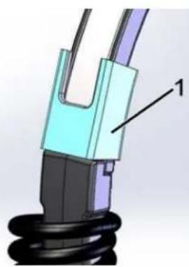
- Using a flat-head screwdriver, carefully p ry the clip from the headband.
natural_image
3D mechanical component diagram showing a spring and housing assembly (no text or symbols)IMPORTANT: Some headsets have a snap feature (2) at each end of the headband cover. If this feature (highlighted in white) is present, the external clips (1) are not used.

natural_image
3D mechanical assembly diagram showing a connector with labeled part '2' and a coiled spring (no text or symbols beyond label)2.3.1.2 Replace Cushions and Windscreen
To ensure optimal product performance, it is recommended you replace ear cushions and headband pads periodically (every six months or sooner, if needed).
2.3.1.2.1 Ear Cushion Replacement
Toreplace the ear cushions, do the following:
- Grasp the edge of the ear cushion where it folds into the slot on the ear cup.
- Gently pull the ear cushion up and away from the ear cup.
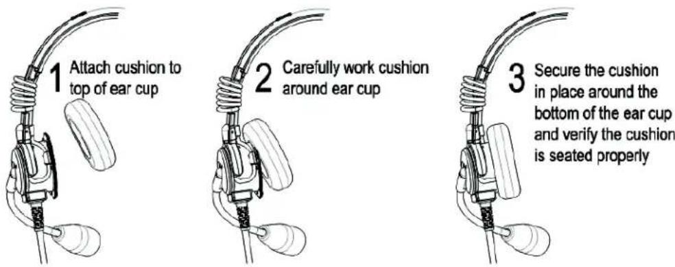
- Starting at the top of the ear cup (1), carefully work the cushion around the cup (2) until it is in place (3).
- Verify the cushion is seated properly by visually inspecting around the cushion before use.
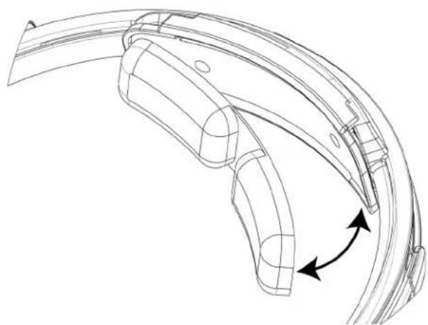
2.3.1.2.2 Headband Pad Replacement
Toreplace the headband pads, do the following:
Early Version Headband
- Carefully remove the headband clips (see "Remove the headband cover clips (if present)" on page 11).
- Gently pull the headband cover away from the headband.
- Starting at the either side of the headband carefully work the replacement cover around the metal headband until it is in place.
Current Version Headpad Holder and Headpad
Toreplace the headpad holder, do the following:
- At one end of the headpad holder, carefully pry the holder from the headband cover.
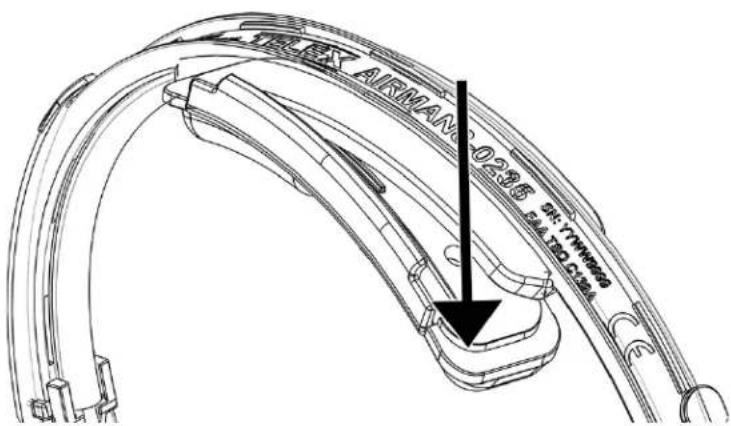
NOTE: Carefully twisting slightly on the headpad holder can help remove the piece easier
-
With the new headpad holder, hook one side of the headpad holder over the headband cover.
-
Snap the other side of headpad holder in place. Be sure the headpad holder edge is over the headband cover.
NOTE: The headpad holder should be centered on the headband cover.
Toreplace the headpad, do the following:
-
Grasp the edge of the headband pad.
-
Gently pull the headband pad away from the headpad holder.
-
Remove the paper from the sticky side of the new headband pad.
-
Align the headband pad with the recessed area on the headpad holder.
-
Firmly press the headband pad into place.
natural_image
Technical line drawing of a curved mechanical component with directional arrows indicating rotation (no text or symbols)2.3.1.3 Remove the mic prefilter
Toremove the prefilter, do the following:
- Using your nail, carefully pry the prefilter from the mic.

natural_image
Close-up of a black mechanical component with two directional arrows indicating upward and downward movement (no text or symbols)2.3.1.4 Remove the Yoke Assembly from the Headband Assembly
To remove the yoke assembly from the headband assembly, do the following:
- On the yoke assembly, use a fingernail to lift the bottom edge of the black plastic spacer.
- Swivel the black plastic spacer to the side and remove it from the assembly.

natural_image
Close-up of a hand holding a metal tool with a black clip, no visible text or symbols- Slide the yoke assembly off of the headband.
2.3.1.5 Boom Side Disassembly
To remove the speaker assembly and sleeve, do the following:
- At the same time, push the t wo retaining cams located in the speaker assembly out of the way.

natural_image
Close-up of a hand holding a mechanical component with visible internal cavities and mounting brackets (no text or symbols)- Rotate the speaker faceplate approximately 15^ clockwise.
IMPORTANT:
Do not pull more than 12mm away from the ear shell at this time.
- Using a T-5 screwdriver, remove three screws (as shown).

natural_image
Interior view of an electronic device showing a circular component with internal circuit board and wiring (no text or symbols visible)- Remove the housing and the yoke/glider assembly.

natural_image
Close-up of a black plastic clamp bracket above a green printed circuit board (no visible text or symbols)- Using a T-5 screwdriver, remove two screws (as shown).

natural_image
Close-up of a green printed circuit board with visible traces and components, no readable text or symbols present.-
Remove the PCBA.
-
Using a soldering iron, carefully disconnect the wires from the speaker, overhead cord, boom mic assembly, and ANR mic solder terminals, as needed.

natural_image
Close-up of a green printed circuit board with visible traces and components, no readable text or symbols present.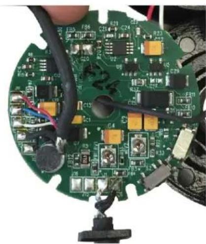
natural_image
Close-up of a green printed circuit board with visible components and wires, no readable text or symbols present.IMPORTANT: Take care to avoid touching the plastic housing with soldering iron.
2.3.1.6 Non-Boom Side Disassembly
NOTE: The following steps need to be done before going forward:
- "Remove the headband cover clips (if present)" on page 11
- "Replace Cushions and Wind screen" on page 12
- "Remove the mic prefilter" on page 14
- "Remove the Yoke Assembly from the Headband Assembly" on page 14
Tore move the speaker assembly and sleeve, do the following:
- Pushing the two retaining cams simult aneously on the speaker assembly, rotate the speaker faceplate approximately 15^ clockwise.
NOTE: To avoid pulling the wires from the board, do not pulling the speaker assembly more than 12mm from the ear shell.

natural_image
Close-up of a hand holding a circular mechanical component with visible slots and mounting hardware (no text or symbols)- Using a T-5 screwdriver, remove three screws (as shown).

natural_image
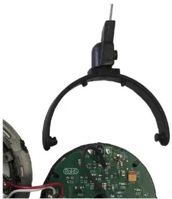
Interior view of a smartwatch with exposed circuit board and internal components (no text or symbols visible)- Remove the housing and the yoke/glider assembly.
natural_image
Close-up of a black plastic clamp bracket above a green printed circuit board (no visible text or symbols)- Using a T-5 screwdriver, remove two screws (as shown).

natural_image
Close-up of a green printed circuit board with visible traces and components, no readable text or symbols present.-
Remove the PCBA.
-
Using a soldering iron, carefully disconnect the wires from the speaker and overhead cord, and ANR mic solder terminals, as needed.

natural_image
Close-up of a green printed circuit board with visible traces and components, no readable text or symbols present.
natural_image
Close-up of a green printed circuit board with visible components and wires, no readable text or symbols present.IMPORTANT:
Take care to avoid touching the plastic housing with soldering iron.
2.3.2 Assembly
2.3.2.1 Boom Side Assembly
Toassemble the boom-side assembly, do the following
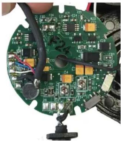
- Solder the overhead cord to PCBA.
| J11 red | |
| J12 blue | |
| J9 white | |
| J10 shield | |
| J17 black |
natural_image
Close-up of a green printed circuit board with visible components and wires, no readable text or symbols present.- Solder the cable assembly to PCBA. (See "Wiring Diagram Airman8-2010 and Airman8-0211" on page 49.)
- T hread the boom mic wires through the center hole.
- Solder the boom mic wires to the PCBA.
| J7 red | |
| J8 green | |
| J18 shield | |
NOTE: Use shield as an anchor point so there is slack on smaller wires.

natural_image
Close-up of a green printed circuit board with visible traces and components (no readable text or symbols)- Using the two shorter screws, attach the PCBA to the boom mic assembly(1).

NOTE: Take care to route the overhead cord and headset cord through the corresponding grooves provided on the boom (2).
- Verify the overhead cord is not caught between the ANR mic (3) and the boom mic housing.
Position 1 is correct, position 2 is incorrect.

- Solder the wires to the speaker.
NOTE: Align the red wire with the polarity dot on the speaker.

natural_image
Interior view of a speaker with visible circuit board and wiring (no text or symbols)- Route the speaker wires through the housing and solder to the PCBA.
J13 red
J14 white

natural_image
Two views of a speaker with exposed circuit board and wiring, showing internal components (no text or symbols visible)- Place yo ke on the housing.
NOTE: Take care to verify the orientation of the yoke, because it does not rotate 360^ .

natural_image
Close-up of a hand holding an open black plastic mechanical component with visible wiring and components (no text or symbols)- Place the switch cover on the ANR switch.
NOTE: The side with the deeper grooves goes toward the speaker.

natural_image
Close-up of a green printed circuit board with red and white wires, showing internal components and mounting points (no readable text or symbols)- Place the housing on the boom mic assembly.
NOTE: Make sure the overhead cord is in the correct slot and the jacket is fully inside the housing. Also, make sure the headset cord is properly located in the housing.

natural_image
Close-up of a black mechanical component with two arrows pointing to features (no visible text or symbols)- Using a T-5 screwdriver, replace the three screws (as shown) to attach the yoke and housing to the PCBA.
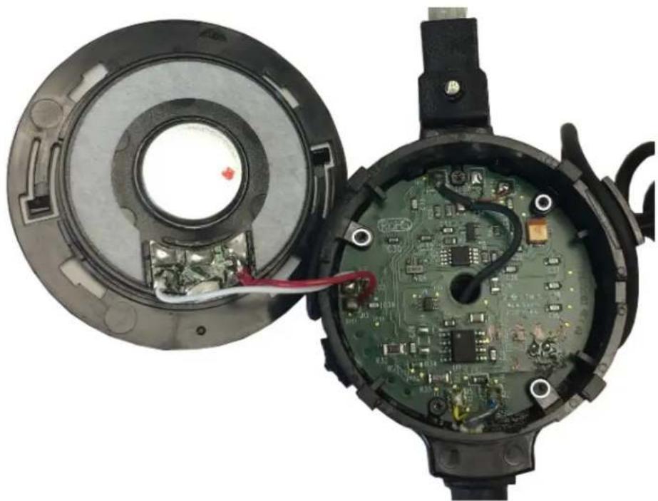
natural_image
Interior view of a device showing an open circuit board with internal components and wiring, no visible text or symbols.- Position the overhead cord in the retaining clip, and then align the knob of the faceplate toward the bottom.

natural_image
Interior view of a device showing an open circular component with internal circuit board and wiring, no visible text or symbols.- Align the four tabs on the faceplate, and then rotate counterclockwise to lock.
NOTE: Verify all four tabs are engaged and retaining tabs are in the groove.
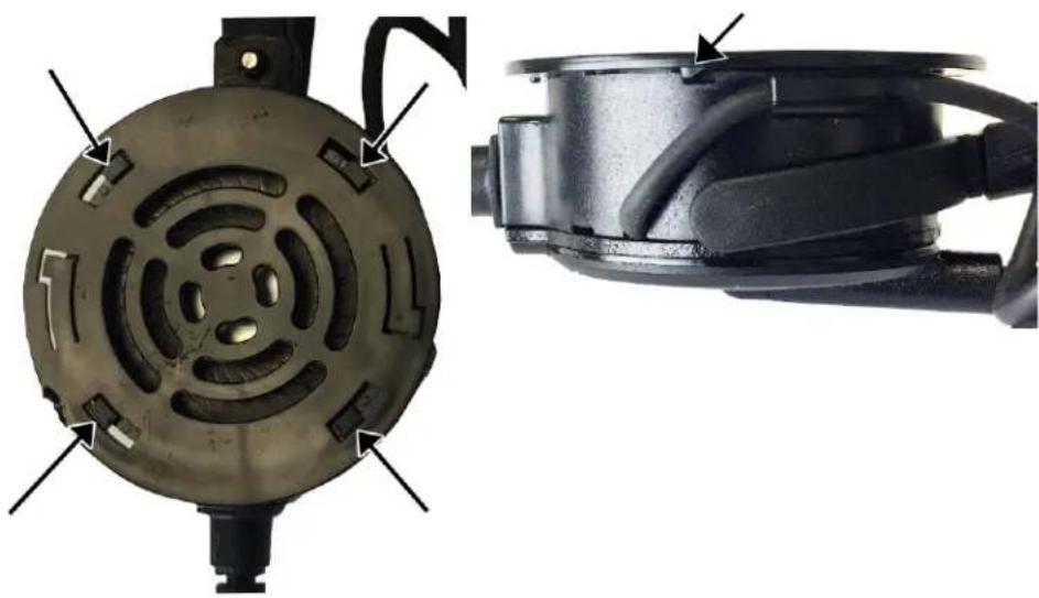
natural_image
Close-up of two mechanical components with internal cutouts and mounting brackets (no visible text or symbols)- Carefully wind the overhead cord around the glider

natural_image
Close-up of a black plastic brake component with coiled cable and wire, isolated on white background (no text or symbols)2.3.2.2 Non-Boom Side Assembly
To assemble the non-boom side assembly, do the following
- Solder ov erhead cord to PCBA.
| J11 red | |
| J12 blue | |
| J9 white | |
| J10 shield | |
| J17 black |

natural_image
Close-up of a green printed circuit board with visible components and wires, no readable text or symbols present.- Using the two shorter screws, attach the PCBA to the cover (1).
NOTE: The location of the alignment posts (1) and the path for the overhead cord (2).

natural_image
Two views of a mechanical device showing internal components and external circuit board (no text or symbols visible)- Solder the wires to the speaker.
NOTE: Align the red wire with the polarity dot on the speaker (as shown).

natural_image
Interior view of a speaker with visible circuit board and wiring (no text or symbols)- Route the speaker wires through the housing and solder to the PCBA.
J13 red
J14 white

natural_image
Two views of a speaker with exposed circuit board and wires, showing internal components (no text or symbols visible)- Place yoke on the housing.
NOTE: Take care to verify the orientation of the yoke, because it does not rotate 360°.
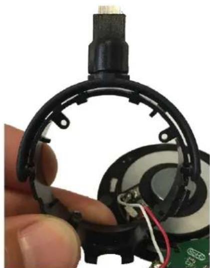
natural_image
Close-up of a hand holding an open electronic device with exposed wiring and components (no visible text or symbols)-
Place the hous ing on the boom mic assembly.
-
Place the cover on the housing.

natural_image
Close-up of a black industrial electrical outlet with a white arrow pointing to the outlet (no visible text or symbols)- Using a T-5 screwdriver, replace the three screws (as shown) to attach the yoke and housing to the PCBA.

natural_image
Interior view of an electronic device showing a circular component with internal circuit board and wiring (no text or symbols visible)- Position the overhead cord in retaining clip and align the knob of the faceplate toward the bottom.

natural_image
Interior view of a device showing internal components including a circular fan, circuit board, and electronic components (no text or symbols visible)- Align the four tabs (shown) on the faceplate, and then rotate counterclockwise to lock.
NOTE: Verify all four tabs are engaged and retaining tabs are in the groove.

natural_image
Close-up of a mechanical component with circular and linear features, showing internal components and mounting brackets (no text or symbols visible)- Carefully wind the overhead cord around the glider

natural_image
Close-up of a black plastic mechanical component with coiled spring and curved wire, isolated on white background (no text or symbols)2.3.2.3 Attach the mic prefilter
To attach the prefilter, do the following:
- Carefully attach the prefilter to the mic.

natural_image
Close-up of a black mechanical component with two directional arrows indicating force or movement (no text or symbols)2.3.2.4 Reinstall the headband cover
To reinstall the headband cover, do the following:
-
Take care to verify the overhead cord lays between the guides.
-
Ensure the cover fully encloses around the headband at both sides.

natural_image
Close-up of a black plastic cable with a coiled spring and a downward arrow indicating compression (no text or symbols)2.3.2.5 Replace the Yoke Assembly from the Headband Assembly
To replace the yoke assembly on the headband assembly, do the following:
- Slide the yoke assembly onto the headband.
- Place the glider stop in the appropriate hole on the glider.
- Swivel the spacer in line with the glider, and then click the bottom edge of the black plastic spacer into the retaining hole.

natural_image
Close-up of a hand holding a metal tool with a black clip, against a white background (no text or symbols visible)2.3.2.6 Replace the headband cover clips (if present)
Toreplace the headband cover clips, do the following:
- Carefully snap the clip on to the headband.
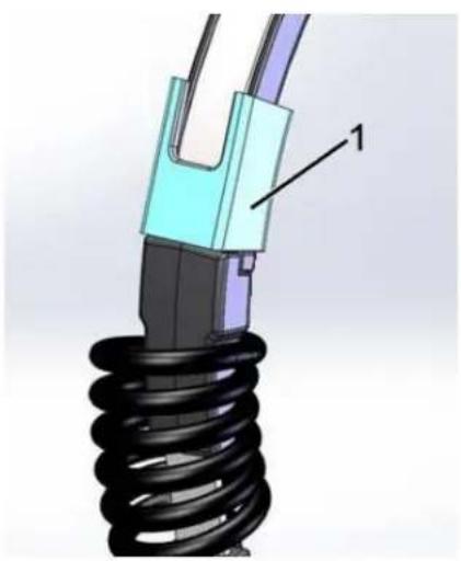
natural_image
3D mechanical component with coiled spring and labeled part 1 (no text or symbols beyond label)IMPORTANT:
Some headsets a snap feature (2) at each end of the headband cover. If this feature (highlighted in white) is present, the external clips (1) are not used.

natural_image
3D mechanical assembly diagram showing a cable connector with labeled part '2' (no text or symbols beyond label)2.3.2.7 Replace Cushions and Windscreen
To ensure optimal product performance, it is recommended you replace ear cushions and headband pads periodically (every six months or sooner, if needed).
2.3.2.7.1 Ear Cushion Replacement
Toreplace the headband pads, do the following:
Early Version Headband
- Carefully remove the headband clips (see "Remove the headband cover clips (if present)" on page 11).
- Gently pull the headband cover away from the headband.
- Starting at the either side of the headband carefully work the replacement cover around the metal headband until it is in place.
Current Version Headpad Holder and Headpad
Toreplace the headpad holder, do the following:
- At one end of the headpad holder, carefully pry the holder from the headband cover.
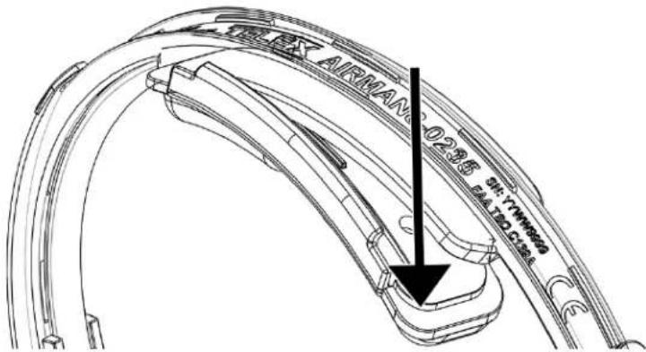
NOTE: Carefully twisting slightly on the headpad holder can help remove the piece easier.
- With the new headpad holder, hook one side of the headpad holder over the headband cover.
- Snap the other side of headpad holder in place. Be sure the headpad holder edge is over the headband cover.
Toreplace the headpad, do the following:
- Grasp the edge of the headband pad.
- Gently pull the headband pad away from the headpad holder.
- Remove the paper from the sticky side of the new headband pad.
-
Align the headband pad with the recessed area on the headpad holder.
-
Firmly press the headband pad into place.

natural_image
Technical line drawing of a curved mechanical component with directional arrows indicating movement (no text or symbols)| IMPORTANT: | The Airman 8 headset was designed, tested, and approved to FAA TSO C139a. The TSO requires the headset meet the minimum performance specifications as defined in RTCA DO-214a. This document and specifications listed here reference the test procedures and equipment used as defined in these standards. Refer to the standard for details on how to perform individual tests. |
3.1 Troubleshoot and Maintenance
The Airman 8 headset is designed so that ANR performance and boom microphone sensitivity can be adjusted as required to meet specification requirements. These are only adjustments that can be made to the headset in order to alter performance. All other maintenance requires replacement of parts, fixing open wires, or removing shorted wires. See specific instructions later in this section for ANR or boom microphone adjustment.
3.1.1 Recommended Maintenance Schedule
NOTE: Ear cushions, headband pads, and microphone wind screens are considered wear items. For proper headset performance, these items need to be inspected and replaced at regular intervals. See the maintenance schedule below for more information. Headset performance diminishes if items are not replaced when deterioration or damage is apparent.
| Task | Per Use | Monthly | 6 Months |
| Check Boom Mic Placement X | |||
| Check Ear Cup Placement X | |||
| Check Headband Fit X | |||
| Inspect & Clean Connectors X | |||
| Clean Ear Cushions X | |||
| Clean Headband Pad X | |||
| Check Connection Cable X | |||
| Inspect & Replace Windscreen X | |||
| Inspect & Replace Ear Cushions X | |||
| Inspect & Replace Headband Pad X |

flowchart
graph TD
    A["Physical Inspection"] --> B["Perform Talk Test"]
    B --> C{Did Talk Test Pass}
    C -->|No| D{What didn't Pass?}
    C -->|Yes| E["Reinstall in Aircraft"]
    D -->|Yes| F["Mic"]
    D -->|No| G["Speaker not working"]
    F --> H["Speaker"]
    G --> I["Speaker"]
    H --> J["ANR"]
    I --> K["ANR"]
    J --> L["ANR"]
    K --> M["AnR"]
    L --> N["Perform Talk Test"]
    M --> N
    N --> O{Did it pass?}
    O -->|Yes| P["Passed"]
    O -->|No| Q["Doesn't pass"]
    P --> R["Reinstall in Aircraft"]
    Q --> S["Talk Test Passed, Minimal Check"]
3.1.2 Physical Inspection
3.1.2.1 Review all plastic parts for cracks or breaks
Toreview plastic parts, do the following:
- Note any parts which need to be replaced
3.1.2.2 Review all cables for obvious signs of damage to the insulting materials
Toreview cables, do the following:
- Look for any cables which have been pulled out of the housings.
- Look for any cables with unnatural or unusual bends or breaks.
- Note any cable assemblies which need to be replaced.
3.1.2.3 Review user replaceable items
To review user replaceable items, do the following:
- Check ear cushions.
- Check headband pads.
- Check microphone windscreen.
- Check clothing clips.
- Note any replaceable items which need to be replaced. Talk Test
3.1.3 Talk Test
When performing a talk test, things to be aware of:
- Note any unusual or unexpected noises, static, and oscillations
- Note any distorted audio
- Turn ANR on and note noise reduction of fans, ambient noise etc.
- Turn ANR off and note noise levels return to normal.
- Verify sound is heard in both ears.

flowchart
graph TD
    A["*ANR is in OFF"] --> B{Does Mic Pass the Talk Test}
    B -->|No| C["Validate Power Source"]
    B -->|Yes| D["Test Sensitivity"]
    C --> E{Is there power to the PCBA}
    E -->|No| F["Replace Cord"]
    E -->|Yes| G["Visual Inspection of all internal wires"]
    G --> H{Are wires damaged}
    H -->|No| I["Power On ANR"]
    H -->|Yes| J["Replace the broken wires"]
    I --> K{Does ANR work}
    K -->|No| L["See ANR Troubleshooting"]
    K -->|Yes| M["But, the microphone doesn't work"]
    L --> N{Is Mic area of PCBA valid}
    N -->|No| O["Replace PCBA"]
    N -->|Yes| P["Replace Microphone Assembly"]
    O --> Q["Validate Mic PCBA"]
    P --> R["Adjust Microphone Sensitivity"]
    R --> S["Microphone Test Complete"]
    S --> T{Does the Mic Meet Sensitivity Specification}
    T -->|No| U["Adjust Microphone Sensitivity"]
    T -->|Yes| V["Close to Microphone Test Complete"]
    U --> T
3.1.4 Microphone Troubleshooting and Workflow
3.1.4.1 Validate Continuity From Plug to PCBA
To validate continuity from the plug to the PCBA, do the following:
- Using an Ohmmeter, place o ne probe on the ring terminal of the plug.
- Place the other probe at J1 on the PCBA.
- Record the me asurement.
- Using an Ohmmeter, place o ne probe on the sleeve terminal of the plug.
- Place the other probe at J2 on the PCBA.
- Record the me asurement.
If the reading is approximately 0, continuity is good. If any other reading is seen, the continuity is bad. Replace the cable.
3.1.4.2 Validate Mic PCBA
- Construct a test circuit.

-
Connect the test circuit to the microphone plug of the headset. For more information, see "Connectors" on page 50.
-
T est for an audio signal. If audio signal is detected, the board the valid. If audio signal is not detected, the board should be replaced.
3.1.4.3 Microphone/Amplifier Sensitivity Check
| IMPORTANT: | The Airman 8 headset was designed, tested, and approved to FAA TSO C139a. The TSO requires the headset meet the minimum performance specifications as defined in RTCA DO-214a. This document and specifications listed here reference the test procedures and equipment used as defined in these standards. Refer to the standard for details on how to perform individual tests. |
Totest the sensitivity of the microphone, do the following:
- Calibrate an art ificial mouth.
- Using the test circuit from the Mic validation and TSO procedures, measure the output of the headset microphone with a digital volt meter.
3.1.4.4 Microphone Sensitivity Adjustment
The microphone gain has been factory-adjusted to the nominal level required for normal radio operation. Microphone sensitivity is adjusted by turning the gain adjustment control.
To adjust the microphone, do the following:
- Rotate the boom mic fully clock wise until the microphone gain adjustment access hole is aligned and open.

natural_image
Close-up of a mechanical component with a circular housing and cable, no visible text or symbols- Insert a 2mm x .5mm flat-bladed screwdriver into the gain adjustment access hole.
NOTE: If gain adjustment access hole is properly aligned, the screwdriver can be inserted approximately 1/2 inch into the hole. If not properly aligned, the screwdriver only inserts approximately 1/8 inch into the hole.
- Turn the gain ad justment potentiometer clockwise to increase the gain. OR
Turn the gain ad justment potentiometer counterclockwise to decrease the gain.
3.1.5 Speaker Troubleshooting and Workflow

flowchart
graph TD
    A["Test Sensitivity"] --> B{PISA?}
    B -->|Yes| C["OK PISA?"]
    B -->|No| D["REMARK?"]
    C --> E["PISA?"]
    D --> F{REMARK?}
    F -->|Yes| G["REMARK?"]
    F -->|No| H["REMARK?"]
    G --> I{REMARK?}
    I -->|Yes| J["REMARK?"]
    I -->|No| K["REMARK?"]
    J --> L{REMARK?}
    L -->|Yes| M["REMARK?"]
    L -->|No| N["REMARK?"]
    M --> O{REMARK?}
    O -->|Yes| P["REMARK?"]
    O -->|No| Q["REMARK?"]
    P --> R{REMARK?}
    R -->|Yes| S["REMARK?"]
    R -->|No| T["REMARK?"]
    S --> U{REMARK?}
    U -->|Yes| V["REMARK?"]
    U -->|No| W["REMARK?"]
    V --> X{REMARK?}
    X -->|Yes| Y["REMARK?"]
    X -->|No| Z["REMARK?"]
    Y --> AA{REMARK?}
    AA -->|Yes| AB["REMARK?"]
    AA -->|No| AC["REMARK?"]
    AB --> AD{REMARK?}
    AD -->|Yes| AE["REMARK?"]
    AD -->|No| AF["REMARK?"]
    AE --> AG{REMARK?}
    AG -->|Yes| AH["REMARK?"]
    AG -->|No| AI["REMARK?"]
    AH --> AJ{REMARK?}
    AJ -->|Yes| AK["REMARK?"]
    AJ -->|No| AL["REMARK?"]
    AK --> AM{REMARK?}
    AM -->|Yes| AN["REMARK?"]
    AM -->|No| AO["REMARK?"]
    AN --> AP{REMARK?}
    AP -->|Yes| AQ["REMARK?"]
    AP -->|No| AR["REMARK?"]
    AQ --> AS{REMARK?}
    AS -->|Yes| AT["REMARK?"]
    AS -->|No| AU["REMARK?"]
    AT --> AV{REMARK?}
    AV -->|Yes| AW["REMARK?"]
    AV -->|No| AX["REMARK?"]
    AW --> AY{REMARK?}
    AY -->|Yes| AZ["REMARK?"]
    AY -->|No| BA{REMARK?}
    BA -->|Yes| BB["REMARK?"]
    BA -->|No| BC{REMARK?}
    BC -->|Yes| BD{REMARK?}
    BD -->|Yes| BE["REMARK?"]
    BD -->|No| BF{REMARK?}
    BE --> BG{REMARK?}
    BG -->|Yes| BH["REMARK?"]
    BG -->|No| BI{REMARK?}
    BH --> BJ{REMARK?}
    BJ -->|Yes| BK["REMARK?"]
    BJ -->|No| BL{REMARK?}
    BK --> BM{REMARK?}
    BM -->|Yes| BN{REMARK?}
    BM -->|No| BO{REMARK?}
    BN --> BP{REMARK?}
    BP -->|Yes| BQ{REMARK?}
    BP -->|No| BR{REMARK?}
    BQ --> BS{REMARK?}
    BS -->|Yes| BT{REMARK?}
    BS -->|No| BU{REMARK?}
    BT --> BV{REMARK?}
    BV -->|Yes| BW{REMARK?}
    BV -->|No| BX{REMARK?}
    BW --> BY{REMARK?}
    BY -->|Yes| BQ
    BY -->|No| BX
3.1.5.1 Speaker Sensitivity and Frequency Response Verification
NOTE: The Airman 8 headset was designed, tested, and approved to FAA TSO C139a. The TSO requires the headset meet the minimum performance specifications as defined in RTCA DO-214a. This document and specifications listed here reference the test procedures and equipment used as defined in these standards. Refer to the standard for details on how to perform individual tests.
All models tested, unless noted otherwise.
Transducer type: Dynamic
Transducer: 600Ω
Impedance (at the earphone plug):
Sensitivity:
Must meet standards outlined in the specifications table in either the technical manual or the technical data sheet.
Frequency Response:
3.1.5.2 Measure the Resistance (Plug to PCBA)
Tomeasure the resistance, do the following:
Using an Ohm Meter, place one probe on J5 and the other probe on J6 or J17.
If measured 300 ± 20% , continuity is good.
If measured at 600 , one of the speaker paths is defective.
If measured at 270Ω or less, there is a short in the speaker path.
3.1.5.3 Validate the Boom Side PCBA
Tovalidate the boom side PCBA, do the following:
- On the boom side PCBA, send a 1kHz sine wave, 1Vrms signal from J5 to J6.
- Verify the A NR switch is in the OFF position.
- Using an oscilloscope, place one probe at J13 and place the other probe at J14. If a signal is found, the board is good and if no sound is heard from the speaker, the speaker or wiring is bad. Determine if the speaker needs to be replaced or the wires need re-soldering. If a signal is not found, the board is not good and should be replaced.
3.1.5.4 Validate the Non-boom Side PCBA
Tovalidate the non-boom side PCBA, do the following:
- On the boom side PCBA, send a 1kHz sine wave, 1Vrms signal from J5 to J6.
- Verify the A NR switch is in the OFF position.
- On the non-boom side board using an oscilloscope, place one probe at J13 and place the other probe at J14.
If a signal is found, the board is good and if no sound is heard from the speaker, the speaker or wiring is bad. Determine if the speaker needs to be replaced or the wires need re-soldering.
If a signal is not found, the board is not good and should be replaced.
3.1.6 ANR Troubleshooting and Workflow

flowchart
graph TD
    A["Troubleshoot Speaker Troubleshoot Mic"] -->|No| B{Does ANR pass the talk test}
    B -->|Yes| C["Final Talk Test"]
    B -->|No| D["Turn the power and ANR on"]
    D --> E{Does ANR work}
    E -->|Yes| F["Adjust ANR"]
    E -->|No| G["Adjust ANR on the headset"]
    G --> H{Does ANR Work}
    H -->|No| I["Measure voltage on .J1 & .J2"]
    H -->|Yes| J["Troubleshoot Speaker Troubleshoot Mic"]
    I --> K{Is the voltage good}
    K -->|No| L["Replace Main PCBA"]
    K -->|Yes| M{Toubleshoot Speaker Troubleshoot Mic}
    M --> N{Are this speakers good?}
    N -->|Yes| O["Replace Boomside PCBA"]
    N -->|No| P{Does ANR Work}
    P -->|Yes| Q["Measure voltage on .J1 and .J2"]
    P -->|No| R["Replace Non-boomside PCBA"]
    Q --> S{Is Voltage Good}
    S -->|Yes| T["Very Continuity of Overhead Wire"]
    S -->|No| U["Replace Continuity of Overhead Wire"]
    S -->|No| V["Replace Overhead Wire"]
    S -->|Yes| W{Does ANR work}
    W -->|No| X["Replace Non-boomside PCBA"]
    W -->|Yes| Y["Replace Overhead Wire"]
    X --> Z{Are this speakers good?}
    Z -->|Yes| AA["Replace Boomside PCBA"]
    Z -->|No| AB["Replace Non-boomside PCBA"]
    AA --> AC{Does ANR Work}
    AC -->|No| AD["Measure voltage on .J1 and .J2"]
    AC -->|Yes| AE["Very Continuity of Overhead Wire"]
    AD --> AF{Is Voltage Good}
    AF -->|No| AG["Replace Non-boomside PCBA"]
    AF -->|Yes| AH{Is Continuity Good}
    AH -->|No| AI["Replace Overhead Wire"]
    AH -->|Yes| AJ{Does ANR Work}
    AJ -->|No| AK["Replace Non-boomside PCBA"]
    AJ -->|Yes| AL["Replace Overhead Wire"]
| IMPORTANT: | The Airman 8 headset was designed, tested, and approved to FAA TSO C139a. The TSO requires the headset meet the minimum performance specifications as defined in RTCA DO-214a. This document and specifications listed here reference the test procedures and equipment used as defined in these standards. Refer to the standard for details on how to perform individual tests. |
| IMPORTANT: | Minimum attenuation requirements are not requirements of FAA TSO. To achieve the minimum attenuation, Bosch approved test system setup is required. |
ANR Test Procedure
3.1.6.0.1 Measuring ANR Circuit Voltages and Switch Function
To measure voltage and switch function on boom-side, do the following:
- Verify the headset main cable plugs are powered on.
- Using a voltmeter, place the ground probe at J10.
- Place the positive probe on TP 14. If measurement is +3.3Vdc, power regulator is good. If measurement is anything other than 3.3Vdc +/-10 power regulator is bad. Replace the board.
To measure the switch functionality on boom side, do the following:
- If regulator is good, verify the ANR switch is in OFF position.
- Place the positive probe at J11. If measure is near 0, switch is open.
- Move the switch to On position. If measure is at 3.3Vdc +/- 10%, the switch is good. If measure at any other measurement, the switch is bad. Replace the board.
To measure the fail-safe control logic for ANR, do following:
- Verify the ANR switch is in the On position.
- Place the voltage meter probe at J12 on boom-side. If measurement is greater than -6Vdc the fail-safe logic is working properly. If the measurement is anything below -6Vdc, fail-safe logic is not working, replace the board.
To measure the switch and overhead cord functionality on non-boom side, do the following:
- If boom-side is good, place the positive probe at J11. If measure is near 0, switch is open.
- Move switch to On position. If measure is at 3.3V +/- 10%, the switch is good. If measure at any other measurement, the switch is bad. Replace the board.
To measure the fail-safe control logic for ANR, do following:
- Verify the ANR switch is in the On position.
- Place the voltage meter probe at J12 on boom-side. If measurement is greater than -6Vdc the fail-safe logic is working properly. If the measurement is anything below -6Vdc, fail-safe logic is not working, replace the board.
IMPORTANT: If a board needs replacement due to ANR adjustment, contact Bosch ASA or Bosch certified facility for replacement and adjustment.
3.1.6.1 Cleaning the Headset and Connectors
IMPORTANT: Do not allow alcohol or any liquid to touch the speaker or microphone element directly.
Toclean the headset, do the following:
Using a mild detergent with water and a soft towel, or isopropyl alcohol wipes, clean the plastic and metal headset parts.
IMPORTANT: Do not soak or allow liquid to puddle on the unit.
3.1.6.2 Cleaning the Ear Cushions and Headband Pads
IMPORTANT: Do not soak cushions or pads.
To clean the ear cushions and headband pad, do the following:
Using a damp (not wet) soft towel or isopropyl alcohol wipes, gently wipe the ear cushions and headband pad thoroughly.
3.1.6.3 Replacing Ear Cushions and Headband Pads
To ensure optimal product performance, it is recommended you replace ear cushions and headband pads periodically (every six (6) months, or sooner if needed). See “Ear Cushion Replacement” on page 12 and “Headband Pad Replacement” on page 12.
Toreplace the ear cushions, do the following:
- Grasp the edge of the ear cushion where it folds into the slot on the ear cup.
- Gently pull the ear cushion up and away from the ear cup.
- Starting at the top of the ear cup (1), carefully work the cushion around the cup (2) until it is in place (3).
3.1.6.4 Installing and Replacing the Hygienic Covers
NOTE: Two hygienic covers are included with the headset. However, extra hygienic covers can be purchased separately.
Toreplace the hygienic covers, do the following:
- Grasp the edge of the hygienic cover where it folds into the slot on the ear cup.
- Gently pull the hygienic cover up and away from the ear cup.
- Starting at the top of the ear cup, carefully work the cover around the ear cup until it is in place.
3.1.6.5 Replacing the Windscreen
The foam windscreen can be cleaned using low pressure air to blow contaminates off from the exterior, If low pressure air does not provide effective results the windscreen should be replaced.
IMPORTANT: Do not use any liquid on the foam windscreen.
To remove the windscreen, do the following:
Grasp the microphone windscreen and gently pull away from microphone.
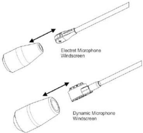
Toreplace the windscreen, do the following:
Slide new windscreen over microphone.
3.1.6.6 Headset Storage
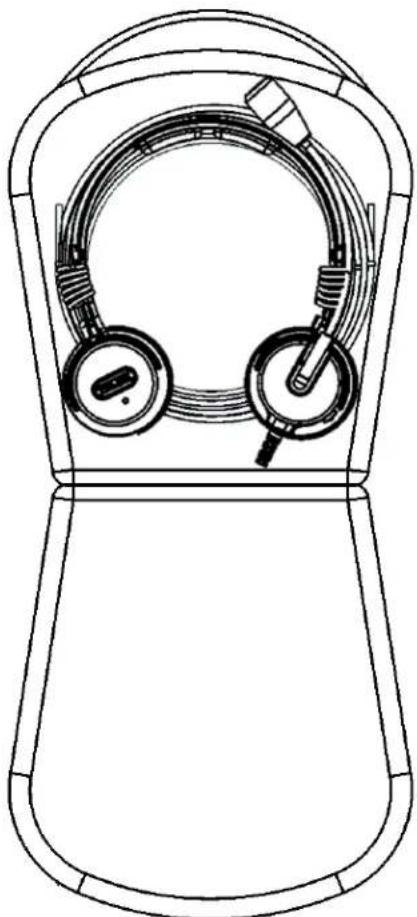
Tostore the headset, do the following:
- Move the boom mic above the headband.

natural_image
Line drawing of a dual-hear electronic device with earbuds and connectors (no text or symbols)-
Fold the ear cups flat.
-
Coil the cord into a loop.
natural_image
Line drawing of a device with two circular earbuds and a handle, shown in top-down view (no text or symbols)- Place the coiled cord and headset in the carrying case.
4.1 Wiring Diagrams
4.1.1 Wiring Diagram Airman8-2010 and Airman8-0211

| Wire Notes Wire Notes | |||||
| J15 | no connection | Outside (mic side) | J6 | outer shield + black | Inside |
| J1 | white | Outside (mic side) | J2 | inner shield + blue | Inside |
| J5 | yellow | Inside | J16 | no connection | Inside |
4.2 Connectors
4.2.1 PJ-068/PJ055 Connector Diagram for Airman8-0210
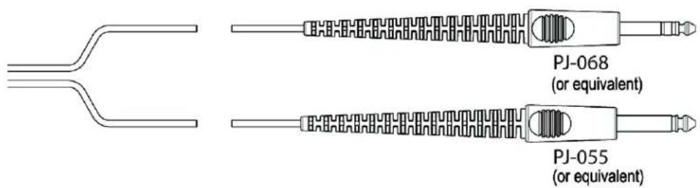
FIGURE 2. PJ-068 and PJ055 Connector Diagram Airman8-0210
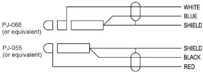
FIGURE 3. PJ-068 and PJ055 Wiring Diagram for Airman8-0210
| PJ-068 or equivalent Description Wiring Color | |
| Tip Not Used | |
| Ring Mic Signal White | |
| Sleeve Mic GND Blue/Shield |
| PJ-055 or equivalent Description Wiring Color | |
| Tip Headphone Signal Red | |
| Sleeve Headphone GND Black/Shield |
4.2.2 XLR Connector Diagram for Airman8-0211

natural_image
Technical line drawing of a mechanical component with threaded end and flange (no text or symbols)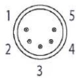
FIGURE 4. XLR Connector for Airman8-0211
| Pin Description Wiring Color | ||
| 1 Headphone Signal Red | ||
| 2 Headphone GND Black/Outer Shield | ||
| 3 Mic Power and Signal White | ||
| 4 Mic GND and ANR Return Blue/Inner Shield | ||
| 5 No Connection | ||
Bosch Security Systems, Inc.
12000 Portland Avenue South
Burnsville, MN 55337 U.S.A.
www.boschcommunications.com
- Purpose of Manual
- Technical Support
- Parts Ordering
- Repairs
- Safety Precautions
- CAUTION:
- Table
- of
- Contents
- CHAPTER 1
- Introduction & Specifications.... 7
- CHAPTER 2
- Parts List and Disassembly/Assembly.... 9
- CHAPTER 3
- Maintenance.... 35
- Airman 8
- CHAPTER 4
- Introduction
- General Description
- Models Covered
- Specifications
- For current specifications, see:
- Reference View
- Parts List and Disassembly/Assembly
- Reference Views
- Disassembly/Assembly
- Disassembly
- Remove the headband cover clips (if present)
- Replace Cushions and Windscreen
- Ear Cushion Replacement
- Headband Pad Replacement
- Early Version Headband
- Current Version Headpad Holder and Headpad
- Remove the mic prefilter
- Remove the Yoke Assembly from the Headband Assembly
- Boom Side Disassembly
- IMPORTANT:
- Non-Boom Side Disassembly
- Assembly
- Boom Side Assembly
- Non-Boom Side Assembly
- Attach the mic prefilter
- Reinstall the headband cover
- Replace the Yoke Assembly from the Headband Assembly
- Replace the headband cover clips (if present)
- Replace Cushions and Windscreen
- Ear Cushion Replacement
- Troubleshoot and Maintenance
- Recommended Maintenance Schedule
- Physical Inspection
- Review all plastic parts for cracks or breaks
- Review all cables for obvious signs of damage to the insulting materials
- Review user replaceable items
- Talk Test
- Microphone Troubleshooting and Workflow
- Validate Continuity From Plug to PCBA
- Validate Mic PCBA
- Microphone/Amplifier Sensitivity Check
- Microphone Sensitivity Adjustment
- Speaker Sensitivity and Frequency Response Verification
- Measure the Resistance (Plug to PCBA)
- Validate the Boom Side PCBA
- Validate the Non-boom Side PCBA
- Measuring ANR Circuit Voltages and Switch Function
- Cleaning the Headset and Connectors
- Cleaning the Ear Cushions and Headband Pads
- Replacing Ear Cushions and Headband Pads
- Installing and Replacing the Hygienic Covers
- Replacing the Windscreen
- IMPORTANT: Do not use any liquid on the foam windscreen.
- Headset Storage
- Wiring Diagrams
- Wiring Diagram Airman8-2010 and Airman8-0211
- Connectors
- PJ-068/PJ055 Connector Diagram for Airman8-0210
- XLR Connector Diagram for Airman8-0211
- Bosch Security Systems, Inc.
Brand : Telex
Model : Airman 8
Category : Headphones