
System 25 EFP 2 MCF - Camera Tripod Sachtler - Free user manual and instructions
Find the device manual for free System 25 EFP 2 MCF Sachtler in PDF.


| Product Type | Fluid Head Tripod System |
| Brand | Sachtler |
| Model | System 25 EFP 2 MCF (Video 25 Plus / V 25 Plus FB head) |
| Weight | 4.5 kg (9.9 lb) |
| Maximum Load | 35 kg (77 lb) |
| Pan Range | 360° |
| Tilt Range | +90° / -75° |
| Counterbalance Steps | 18 |
| Drag Grades (Horizontal/Vertical) | 7 + 0 each |
| Temperature Range | -40°C to 60°C (-40°F to 140°F) |
| Balance Plate Sliding Range | 100 mm (4.3 in) for FB version, 110 mm for standard |
| Tripod Fitting | 150 mm (6 in) half ball or flat base (convertible) |
| Pan Bar | Telescopic, 18/22 mm diameter, 350-520 mm length |
| Batteries (for illumination) | 3 x 625 U or LR9 button cells |
| Illumination Type | Self-illuminating spirit bubble (tap activated) |
| Quick Release System | Touch & Go with safety lock |
| Safety Features | Tilt safety lock, horizontal and vertical brakes |
| Modular Design | Balance plate and flat base conversion possible |
| Maintenance | Set damping to max and open brakes during transport; clean with dry cloth |
| Warranty | Extended warranty available via registration at www.sachtler.com |
Frequently Asked Questions - System 25 EFP 2 MCF Sachtler
User questions about System 25 EFP 2 MCF Sachtler
0 question about this device. Answer the ones you know or ask your own.
Ask a new question about this device
Download the instructions for your Camera Tripod in PDF format for free! Find your manual System 25 EFP 2 MCF - Sachtler and take your electronic device back in hand. On this page are published all the documents necessary for the use of your device. System 25 EFP 2 MCF by Sachtler.
USER MANUAL System 25 EFP 2 MCF Sachtler

sachtler
We want you to receive Sachtler products that are always state of the art.
Therefore we reserve the right to make changes based on technical advances.
Vitec Group Videocom Division
www.vitecgroup.com
Erfurter Strasse 16 Postfach / P.O.BOX 2039
D-85386 Eching D-85380 Eching
Germany Germany
Telefon: (+49) 89 321 58 200
Telefax: (+49) 89 321 58 227
E-Mail: contact@sachtler.de
Homepage: http://www.sachtler.com
Table of contents
1 Safety instructions ....1
2 Operating elements....1
3 Operation ....2
3.1 Levelling of the fluid head....2
3.2 Removing of the camera plate....2
3.3 Mounting of the camera....2
3.4 Removing of the camera....3
3.5 Positioning of the camera....3
3.6 Adjusting the camera's counterbalance ....4
3.7 Setting of the damping ....5
3.8 Brakes ....5
3.9 Support for viewfinder extension....5
3.10 Change of the batteries ....5
3.11 Transport setting of damping, counterbalance and brakes ....6
4 Technical specifications....7
4.1 General data ....7
4.2 Dimensions 8
5 The modular system ....8
5.1 Conversion to include different balance plate......9
5.2 Conversion of the Video 25 Plus to include flat base ....9
6 Warranty....10
Inhaltsverzeichnis
EC - Declaration of Conformity
Here we declare that this product complies with the requirements of the applied directives.
standards and regulations for safety and health, if used for its intended application.
This declaration becomes invalid. If any changes have been made without our agreement.
Standards and Regulations:
EN 55103-1:2006
1 Safety instructions
When the camera is mounted, the clamping screw of the fluid head must only be released if camera and tripod are secured against falling over.
When placing the camera plate into the fluid head, make sure not to hold fingers within the range of the locking lever, since it will snap back.
When releasing the vertical brake make sure that the camera is secured against any sudden movement.
Do not operate the fluid head upside down without the necessary securing devices, i.e. ropes etc.
2 Operating elements
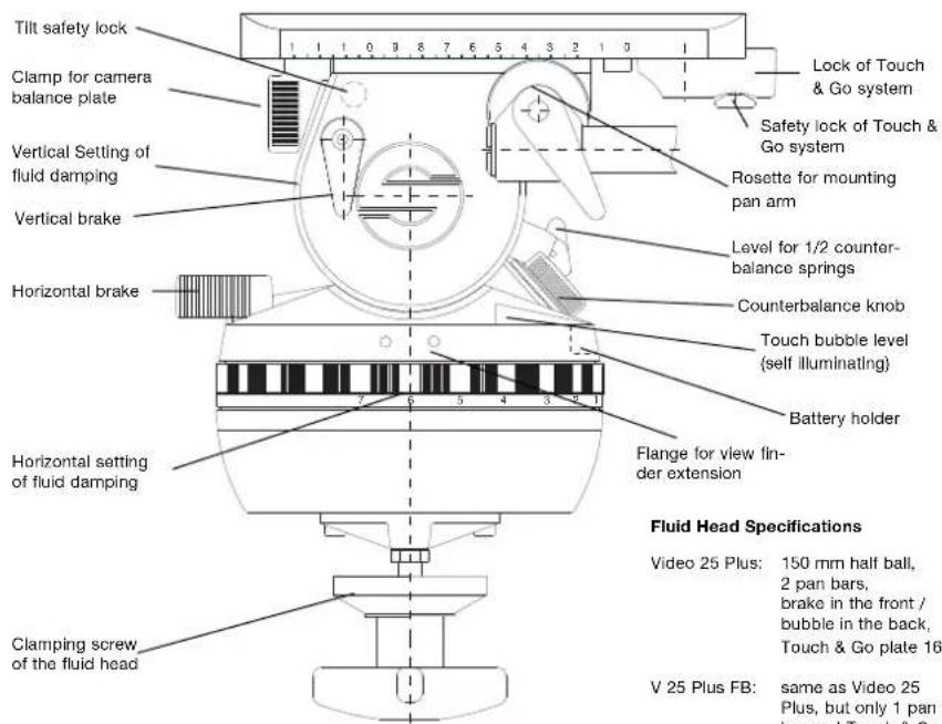
Fluid Head Specifications
Video 25 Plus: 150 mm half ball, 2 pan bars, brake in the front / bubble in the back, Touch & Go plate 16
V 25 Plus FB: same as Video 25 Plus, but only 1 pan bar and Touch & Go plate 35
3 Operation
3.1 Levelling of the fluid head (Video 25 Plus only)
The fluid head has a bubble to facilitate levelling.
Apply the vertical brake of the fluid head and hold the camera with one hand. Open the clamping screw of the fluid head and move the head in such a way, that the bubble moves into the levels black circle. Tighten the clamping screw firmly.
Touch Bubble
The fluid head has a self illuminating spirit bubble which allows easy levelling even under unfavourable lighting conditions.
The illumination is activated by strong tapping on the bubble. Depending on the force applied the bubble will glow up to 45 seconds.
3.2 Removing of the camera plate
The fluid head comes with a Touch & Go quick release plate.
Hold the camera plate with one hand.
→Grasp the locking lever with your thumb and index and pull down the red safety button.
→Move the locking lever as far as possible to the left (audible clicking) and take out the camera plate.
3.3 Mounting of the camera
Attach the camera plate to the tripod adapter plate (camera accessory) around the camera's centre of gravity.
→Turn the counterbalance knob to position 7.
Apply horizontal brake and release vertical brake.
The springs of the counterbalance engage automatically by tilting the camera through the horizontal position (audible clicking).
→Lock the head with the tilt safety lock.
The blocking and clicking into position of the tilt safety lock is achieved by pulling out the red knob and turning it 90°. Green marking on the red knob becomes visible.
Make sure that the tilt safety lock has engaged. (The head can't be tilted any more.)
→Put the front of the camera plate in place first.
By fitting the camera onto the head it will lock automatically and the locking lever will snap back audibly into its initial position.
3.4 Removing of the camera
→Lock the head with the tilt safety lock.
The blocking and clicking into position of the tilt safety lock is achieved by pulling out the red knob and turning it 90°. Green marking on the red knob becomes invisible.
Make sure that the tilt safety lock has engaged. (The head can't be tilted any more.)
→Hold the camera with one hand.
→Grasp the locking lever with your thumb and index and pull down the red safety button.
→Move the locking lever as far as possible to the left and take out the camera plate.
3.5 Positioning of the camera
Hold the camera by securing the pan bar.
Apply horizontal brake and release vertical brake and tilt safety lock by pulling out the red knob and turning it 90°. Green marking on the red knob becomes visible (rocking the pan bars up and down will facilitate this).
→Select 0 on the vertical drag adjustment ring.
→Open the lock of sliding balance plate.
You have to push back red lever underneath the balance plate as far as possible.
→By moving the sliding balance plate forwards and backwards you have to find the position where the camera is balanced horizontally. Rear-heavy cameras are moved to the front, front-heavy cameras are moved to the back. You will find it easier when holding the camera in a horizontal position.
Lock the sliding balance plate by pulling the red lever into its initial position.
Caution: If you can't manage to centre the camera, you should move the camera plate to a different position on the tripod mounting adapter.
3.6 Adjusting the camera's counterbalance
→Hold the camera by securing the pan bar.
Turn the counterbalance knob to that number which best compensates for the weight of the camera.
After each spring is released, check if the camera will remain in a tilted position, without moving upwards or downwards significantly.
Please note: A lower counterbalance setting becomes immediately effective in any tilt position. An increase of the counterbalance setting will only be effective in the horizontal position (springs must click in audibly).
3.7 Setting of the Damping
The fluid head is equipped with seven damping levels horizontally and vertically and a zero setting. Turning the vertical or horizontal setting one selects the desired level of the fluid damping. Turn the setting ring to "0" in order to switch off the damping completely.
Make sure that you always turn the setting to the next indexed position. Engage the retainer pins by slowly panning or tilting the camera.
ATTENTION: Panning or tilting the camera with settings between the indexed position can damage the retainer pins and/or disks.
If you set the setting rings on the same index number (e.g. "3") the degree of the horizontal and vertical damping is identical and thus enables precise diagonal panning movements without jerks and vibrations.
3.8 Brakes
The horizontal brake applies the lock for the pan and the vertical brake for the tilt movement. Both brakes are vibrationless and can be used during shooting.
3.9 Support for viewfinder extension
The fluid head Plus has on both sides a preparation to accept a support system for a viewfinder extension.
3.10 Change of the batteries
The illumination is powered by three standard type button cells (625 U or LR9) located in the battery holder, which can be opened with a sharp object such as a screwdriver.
Make sure to insert the new batteries according to the "plus" and "minus" symbols as indicated in the covering plate.
The batteries last for about 2000 illumination cycles.
3.11 Transport setting of damping, counterbalance and brakes
To ensure smooth operation of the setting rings for the damping over the long life time period of the fluid head, you should turn both setting rings from position "0" to maximum position, before and after the use of the fluid head.
Setting during transportation: the most important issue is to open both brakes - horizontal and vertical.
Counterbalance and damping should be set to maximum position.
4 Technical specifications
4.1 General data
Counterbalance: 18 steps (depends on COG of the camera)
Balance plate: 100 mm (4.3 in) sliding range (Video 25 Plus FB) 110 mm (Video 25 Plus)
Grades of drag: horizontal, and vertically 7 each and 0
Tilt angle: +90° / -75°
Panning range: 360°
Temperature range: -40°C (-40°F) to 60°C (140°F)
Weight: 4.5 kg (9.9 lb)
Max. load: 35 kg (77 lb)
Camera fitting: Touch & Go system
Tripod / Pedestal 150 mm (6 in) ball / flat base fitting:
Pan bar: telescopic with attachment diameter of 18/22 mm (0.7 / 0.8 in), length 350 to 520 mm (13.8 - 20.5 in)
Batteries: 3 each 625 U or LR969
4.2 Dimensions
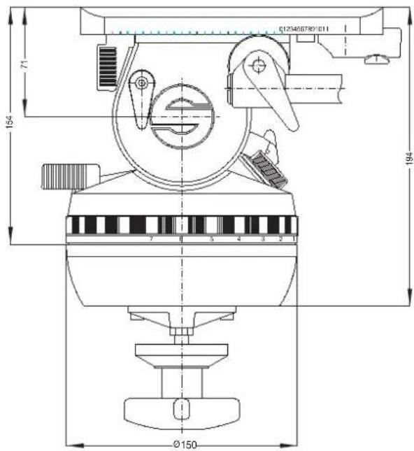
5 The modular system
Due to the Video 25 Plus / FB modular design you may perform certain modifications yourself. In order to safe time you can do all work with an allen wrench #4 unless otherwise specified.
The following modifications can be performed:
Conversion of the fluid head to include different balance plate
Conversion of Video 25 Plus to include flat base
5.1 Conversion of the fluid head to include different balance plate
Remove the camera plate.
Open the lock of the balance plate by pushing back red lever underneath the balance plate as far as possible.
Keep on moving the balance plate backwards until you see an allen screw in the camera plate's receptacle.
Remove the screw.
Now the balance plate can slide off the base plate. It can be exchanged for a different one with either smaller or bigger camera plate.
Don't forget to tighten again the allen screw in the camera plate's receptacle. It serves as a stopper.
The conversion is done.
5.2 Conversion of the Video 25 Plus to include flat base
Put the Video 25 Plus upside down, so that you can access the bottom of the head.
Next to the centre bolt you will see 4 allen screws. Those have to be unscrewed and the whole piece has to be removed.
Now the Video 25 Plus can be mounted onto flat base tripods and pedestals with 4 bolt flat base directly. For Quickfix mount and all Sachtler pedestals the Multi Disc from the Sachtler accessory range is required.
It is mounted onto the fluid heads 4 bolt flat base.
6 Warranty
Warranty expires if:
The fluid head was operated improperly or not in line with the specified technical data, or
the head housing was opened by unauthorised personnel.
We reserve the right to make changes based on technical advances.
Please register at www.sachtler.com for an extended warranty period.
Vitec Brazil Technologies Ltda
Rua Quintana, 950 - cj.32
Brooklin
Sâu Paulo, 04569-011
Brazil
Tel: +55 11 5102 4001
Fax: +55 11 5103 1164
JAPAN
Sachtler Japan
P.A. Building 4F
3-12-6 Aobadai
Meguro-ku
Tokyo 153-0042
Japan
Tel: +81 3 5457 1381
Fax: +81 3 5457 1382
CHINA
Vitec China
Rm 706, Tower B
Derun Building
YongAn Dongli A No.8
Jianwai Ave., Chaoyang District
100022 Beijing
China
Tel: +86 10 8528 8748
Fax: +86 10 8528 8749
SINGAPORE
Vitec Videocom Pte Ltd.
6 New Industrial Road
02-02 Hoe Huat Industrial Building
Singapore 536199
Tel: +65 629 757 76
Fax: +65 629 757 78
FRANCE
Vitec Videocom
William Vinten Building
Western Way
Bury St. Edmunds
Suffolk IP33 3TB
UK
Tel: +44 1284 776 700
Fax: +44 1284 750 560
Sales Fax: +44 1284 757 929
GERMANY
Vitec Videocom GmbH
Headquarters
Erfurter Strasse 16
85386 Eching
Germany
Tel: +49 89 321 58 200
Fax: +49 89 321 58 227
USA
Vitec Videocom Inc.
709 Executive Blvd.
Valley Cottage
New York 10989
USA
Tel: +1 845 268 0100
for more information, visit
www.sachtler.com


- TABLE OF CONTENTS
- INHALTSVERZEICHNIS
- EC - DECLARATION OF CONFORMITY
- 1 SAFETY INSTRUCTIONS
- FLUID HEAD SPECIFICATIONS
- 3 OPERATION
- 3.1 LEVELLING OF THE FLUID HEAD (VIDEO 25 PLUS ONLY)
- TOUCH BUBBLE
- 3.2 REMOVING OF THE CAMERA PLATE
- 3.3 MOUNTING OF THE CAMERA
- 3.4 REMOVING OF THE CAMERA
- 3.5 POSITIONING OF THE CAMERA
- 3.6 ADJUSTING THE CAMERA'S COUNTERBALANCE
- 3.7 SETTING OF THE DAMPING
- 3.8 BRAKES
- 3.9 SUPPORT FOR VIEWFINDER EXTENSION
- 3.10 CHANGE OF THE BATTERIES
- 3.11 TRANSPORT SETTING OF DAMPING, COUNTERBALANCE AND BRAKES
- 4 TECHNICAL SPECIFICATIONS
- 4.1 GENERAL DATA
- 4.2 DIMENSIONS
- 5 THE MODULAR SYSTEM
- 5.1 CONVERSION OF THE FLUID HEAD TO INCLUDE DIFFERENT BALANCE PLATE
- 5.2 CONVERSION OF THE VIDEO 25 PLUS TO INCLUDE FLAT BASE
- 6 WARRANTY
- JAPAN
- CHINA
- SINGAPORE
- HOE HUAT INDUSTRIAL BUILDING
- FRANCE
- GERMANY
- USA
Brand : Sachtler
Model : System 25 EFP 2 MCF
Category : Camera Tripod