
RM-IP10 - Joystick SONY - Free user manual and instructions
Find the device manual for free RM-IP10 SONY in PDF.


| Brand | Sony |
| Model | RM-IP10 |
| Product Type | Remote control panel (joystick) for PTZ camera |
| Dimensions (W × H × D) | 391.3 mm × 165 mm × 145.9 mm |
| Weight | Approx. 950 g |
| Power Supply | 12 V DC (AC adapter supplied); consumption 3.6 W max |
| Communication Methods | IP (up to 112 cameras), RS-232C/RS-422 (up to 7 cameras) |
| Connectors | VISCA RS-232C (mini-DIN 8-pin), VISCA RS-422 (9-pin), TALLY/CONTACT (9-pin), LAN RJ-45 |
| Main Functions | Pan/Tilt/Zoom control, presets (16 positions), auto/manual focus, white balance, exposure, backlight compensation, lock |
| Operating Temperature | 0 °C to 40 °C |
| Maintenance and Cleaning | Soft, dry cloth; avoid volatile solvents (alcohol, benzene, thinners) |
| Safety | Use the supplied Sony AC adapter; do not expose to rain/humidity; do not open the housing |
| Supplied Accessories | AC adapter, power cord, 2 RS-422 connector plugs, safety regulations |
| Estimated Service Life (capacitor) | Approx. 5 years under normal conditions |
Frequently Asked Questions - RM-IP10 SONY
User questions about RM-IP10 SONY
0 question about this device. Answer the ones you know or ask your own.
Ask a new question about this device
Download the instructions for your Joystick in PDF format for free! Find your manual RM-IP10 - SONY and take your electronic device back in hand. On this page are published all the documents necessary for the use of your device. RM-IP10 by SONY.
USER MANUAL RM-IP10 SONY
IP Remote Controller
Operating Instructions ____ GB
Mode d'emploi FR
Before operating the unit, please read this manual thoroughly and retain it for future reference.
Owner's Record
The model and serial numbers are located on the bottom. Record the serial number in the space provided below. Refer to these numbers whenever you call upon your Sony dealer regarding this product.
Model No. RM-IP10
Serial No. ____
WARNING
To reduce the risk of fire or electric shock, do not expose this apparatus to rain or moisture.
To avoid electrical shock, do not open the cabinet. Refer servicing to qualified personnel only.
WARNING
Use the Sony AC power adapter provided with this equipment as a power supply source. Any other power sources may result in hazards such as a fire. Disconnect device of this equipment is the mains plug of the AC adapter. The mains plug on this equipment must be used to disconnect mains power. Please ensure that the socket outlet is installed near the equipment and shall be easily accessible. In the event of abnormal operations, disconnect the mains plug.
IMPORTANT
The nameplate is located on the bottom.
For the customers in the U.S.A.
This equipment has been tested and found to comply with the limits for a Class A digital device, pursuant to part 15 of the FCC Rules. These limits are designed to provide reasonable protection against harmful interference when the equipment is operated in a commercial environment. This equipment generates, uses, and can radiate radio frequency energy and, if not installed and used in accordance with the instruction manual, may cause harmful interference to radio communications. Operation of this equipment in a residential area is likely to cause harmful interference in which case the user will be required to correct the interference at his own expense.
You are cautioned that any changes or modifications not expressly approved in this manual could void your authority to operate this equipment.
All interface cables used to connect peripherals must be shielded in order to comply with the limits for a digital device pursuant to Subpart B of part 15 of FCC Rules.
This device complies with part 15 of the FCC Rules.
Operation is subject to the following two conditions: (1) This device may not cause harmful interference, and (2) this device must accept any interference received, including interference that may cause undesired operation.
For the customers in Canada
This Class A digital apparatus complies with Canadian ICES-003.
For the customers in Europe, Australia and New Zealand
WARNING
This is a Class A product. In a domestic environment, this product may cause radio interference in which case the user may be required to take adequate measures. In the case that interference should occur, consult your nearest authorized Sony service facility.
For the customers in Europe
This apparatus shall not be used in the residential area.
Location and Function of Parts 5
Connections and Operations
Connections 12
Connecting cameras that are compatible with IP connection 12
Connecting cameras equipped with VISCA RS-232C connector 14
Connecting cameras equipped with VISCA RS-422 connector 15
Connecting the BRU-SF10 Optical Multiplex Unit 16
Connecting a video switcher ....17
Turning on the Power 17
Storing the Camera Settings in Memory
- Presetting Feature .... 18
Setting the speed of the camera moving to a preset position 19
Using the Function Stored in the Memory of the
RM-IP10 20
Setting a limit on the maximum panning/tilting speed 20
To Return to the Factory Setting 21
Appendix
Troubleshooting 22
Specifications 23
Dimensions 24
Pin Assignments 24
Using the VISCA RS-422 connector plug ..... 25
Example connection of TALLY/CONTACT connector for input 26
Example connection of TALLY/CONTACT connector for output 26
Input Waveform of TALLY/CONTACT Connector ....26
License 27
About the RM-IP Setup Tool
This is a software tool for configuring remote controller settings. It is used to configure the following.
- IP address settings
- Camera assignments
- Swapping camera numbers
- Checking camera tables
Install the software on the setup PC for the unit.
The setup tool software and setup tool guide can be downloaded from the download site.
For details, refer to the "RM-IP Setup Tool guide."
- Microsoft and Windows are registered trademarks of Microsoft Corporation in the United States and/or other countries.
- Intel and Core are registered trademarks of Intel Corporation or its subsidiaries in the United States and other countries.
All other company and product names are trademarks or registered trademarks of the respective companies or their respective makers.
Data and security
- SONY WILL NOT BE LIABLE FOR DAMAGES OF ANY KIND RESULTING FROM A FAILURE TO IMPLEMENT PROPER SECURITY MEASURES ON TRANSMISSION DEVICES, UNAVOIDABLE DATA LEAKS RESULTING FROM TRANSMISSION SPECIFICATIONS, OR SECURITY PROBLEMS OF ANY KIND.
- Depending on the operating environment, unauthorized third parties on the network may be able to access the unit. When connecting the unit to the network, be sure to confirm that the network is protected securely.
- Do not browse any other website in the Web browser while making settings or after making settings. Since the login status remains in the Web browser, close the Web browser when you complete the settings to prevent unauthorized third parties from using the unit or harmful programs from running.
Getting Started
Precautions
Operating or storage location
Operating or storing the unit in the following locations may cause damage to the unit:
- Extremely hot or cold places (Operating temperature: 0^ to 40^ [32 °F to 104 °F])
- Exposed in direct sunlight for a long time, or close to heating equipment (e.g., near heaters)
- Close to sources of strong magnetism
- Close to sources of powerful electromagnetic radiation, such as radios or TV transmitters
- Locations subject to strong vibration or shock
Ventilation
To prevent heat buildup, do not block air circulation around the unit.
Transportation
When transporting the unit, repack it as originally packed at the factory or in materials equal in quality.
Cleaning
- Use a soft, dry cloth to clean the external surfaces of the unit. Stubborn stains can be removed using a soft cloth dampened with a small quantity of detergent solution, then wipe dry.
- Do not use volatile solvents such as alcohol, benzene or thinners as they may damage the surface finishes.
On moisture condensation
If the unit is suddenly taken from a cold to a warm location, or if ambient temperature suddenly rises, moisture may form on the outer surface of the unit and/or inside of the unit. This is known as condensation. If condensation occurs, turn off the unit and wait until the condensation clears before operating the unit. Operating the unit while condensation is present may damage the unit.
On parts life expectancy
The life expectancy of the AC adapter and the electrolytic capacitor is about 5 years under normal operating temperatures and normal usage. The life expectancy changes depending on the usage environment.
Overview
Features
Operate up to 112 cameras\* by using the IP connection
You can operate up to 112 cameras by using a commercially available switching hub. The cameras can be operated by up to five IP remote controllers connected to the network ^*2 .
By using the supplied setup software, you can set the IP addresses of the 112 cameras and five IP remote controllers from your PC.
*1 Supported cameras: BRC-H900/BRC-Z330 with the optional BRBK-IP10 IP control card inserted, BRC-Z700 with the optional BRBK-IP7Z IP control card inserted, SRG-300H/301H/120DH/121DH/120DU/120DS/HD1/300SE/301SE/201SE/360SHE/280SHE/X400/201M2/X120/HD1M2, BRC-X1000/H800/H780/X400/X401
*2 The network should be independent from other systems and networks. When controlling a camera that is on a network of a different segment via a router, that network also should be independent. Using on a line with a packet loss or delay may cause a malfunction. Do not connect to the network that uses a public network, such as the internet. Do not have more than 112 cameras, 5 IP remote controllers, one PC for setting, connected with the IP connection.
The router is compatible with the IP remote controller with the firmware version 2.1 or higher, and BRBK-IP10/IP7Z optional card with the firmware version 2.1 or higher.
Compatible with VISCA RS-232C/RS-422\*3
You can select the one communication method from the IP, RS-232C, or RS-422 connection.
The unit can control up to seven cameras when the VISCA RS-232C/RS-422 connection is selected.
*3 Supported cameras: SRG-120DH/121DH/120DU/120DS/HD1 are not compatible with the RS-422 connection. SRG-300SE/301SE/201SE/360SHE/280SHE, BRC-X1000/H800/H780/X400/X401, or SRG-X400/201M2/X120/HD1M2 are not compatible with the RS-232C connection. BRC-H900/Z700/Z330 or SRG-300H/301H are compatible with the RS-232C/RS-422 connection.
Note
You cannot use the multiple communication methods simultaneously.
The optical three-axis joystick allows comfortable pan/tilt/zoom operations.
Easy operation of versatile camera adjustments
Using the buttons on the unit, you can easily perform various adjustments such as auto focusing, one-push auto focus adjustment, AE adjustment, one-push auto white balance adjustment and backlight compensation.
Preset feature to save camera settings
You can save up to 16 combinations of camera settings such as pan/tilt/zoom positions and other camera adjustment values, in the memory of the camera.
Notes
- The operable functions are limited to those that the camera is equipped with.
- This manual mainly explains the functions of the unit for the BRC-H900 camera.
When another camera is connected, refer to the Operating Instructions supplied with that camera for available functions.
System requirements for the PC
To use the supplied software, you need a PC with the following specifications.
- CPU: Intel Core2 Duo 2.4 GHz or higher (recommended)
• Memory: 1 GB or more (recommended)
• Hard disk: More than 50 MB available
• LAN port: 10BASE-T or 100BASE-TX - OS: Microsoft Windows 7 (32bit, 64bit), Windows 8.1 Pro (32bit, 64bit), Windows 10 Pro (32bit, 64bit)
Location and Function of Parts
This manual is based on operation of the RM-IP10 when used with a BRC series Color Video Camera.
Front
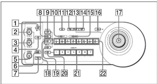
① LOCK button and JOYSTICK/KNOB indicators
Each time you press the LOCK button for more than one second, the JOYSTICK or/and KNOB indicator(s) turn on or off.*
When the JOYSTICK indicator is on, the 17 Joystick, 13 PAN-TILT RESET button, and 16 MENU button cannot be operated.
When the KNOB indicator is on, the 2 VALUE/R control, 3 BRIGHT/B control, 4 MODE button, 5 FOCUS control, 6 AUTO/MANUAL button, and 7 ONE PUSH AF button cannot be operated.
* For details of the lighting pattern of the JOYSTICK/KNOB indicators, check the setting of DIP 1 switches 7 and 8.
2 VALUE/R control
When the brightness adjustment mode is selected with the MODE button (with the VALUE indicator lit):
This control adjusts the value of the item (SHUTTER or IRIS) selected on the camera.
When the VALUE indicator is lit, the function of the control varies according to the exposure mode selected on the camera. For details, see “Functions of the VALUE and BRIGHT controls” on page 6.
When the white balance adjustment mode is selected with the MODE button (with the R indicator lit):
This control adjusts the R. GAIN (red gain).
The function of the control with the R indicator lit varies according to the white balance mode selected
on the camera. For details, see "Functions of the R and B controls" on page 6.
③ BRIGHT/B control
When the brightness adjustment mode is selected with the MODE button (with the BRIGHT indicator lit):
This control adjusts the value of the brightness of the camera, etc.
When the BRIGHT indicator is lit, the function of the control varies according to the exposure mode selected on the camera. For details, see “Functions of the VALUE and BRIGHT controls” on page 6.
When the white balance adjustment mode is selected with the MODE button (with the B indicator lit):
This control adjusts the B. GAIN (blue gain).
The function of the control with the B indicator lit varies according to the white balance mode selected on the camera. For details, see “Functions of the R and B controls” on page 6.
Functions of the VALUE and BRIGHT controls
The functions of the VALUE control and the BRIGHT control change according to the exposure mode setting on the camera, as follows:
| Exposure mode on the camera | Function of VALUE control | Function of BRIGHT control |
| FULL AUTO Not assigned Exposure | ||
| BACK LIGHT*3 | Not assigned | compensation level control (When the exposure compensation function is activated on the camera.) |
| SPOT LIGHT*3 | Not assigned | |
| SHUTTER Pri Shutter speed control | ||
| IRIS Pri Iris control | AE level control*4 | |
| GAIN Pri*2 | Gain control*2 | |
| BRIGHT*5 | Not assigned Brightness level control*5 | |
| MANUAL Shutter speed control | Iris control*1 | |
*1 Iris and gain controls are operable when DIP 2 switch 3 is set to ON.
*2 Available for the BRC-Z700 and BRC-Z330 only
*3 Available for the BRC-H900 only
*4 Available for the BRC-X1000/H800/H780/X400/X401 and SRG-X400/201M2/X120/HD1M2/360SHE/280SHE/300SE/301SE/201SE/300H/301H/120DH/121DH/120DU/120DS/HD1 only
*5 Available for the SRG-360SHE/280SHE/300SE/301SE/201SE/300H/301H/120DH only
Functions of the R and B controls
When the white balance adjustment mode is selected with the MODE button of this unit, the functions of the R control and B control change according to the white balance mode setting in the menu of the camera.
| White balance mode on the camera | Function of the R control | Function of the B control |
| MANUAL Red gain control Blue gain control | ||
| AUTO1^*1*3 , AUTO2^*1*3 | WB R.SHIFT control*1, OFFSET control*3 | WB B.SHIFT control*1, OFFSET control*3 |
| AUTO^*2 | OFFSET control*2 | OFFSET control*2 |
| ONE PUSH | WB R.SHIFT control*1, OFFSET control*2 *3 | WB B.SHIFT control*1, OFFSET control*2 *3 |
*1 Available for the BRC-Z700/Z330 only
*2 Available for the BRC-H900 and SRG-360SHE/280SHE/300SE/301SE/201SE/300H/301H/120DH/121DH/120DU/120DS/HD1 only
*3 Available for the BRC-X1000/H800/H780/X400/X401 and SRG-X400/201M2/X120/HD1M2 only
4 MODE button
Press this button to select the function of the VALUE/R control and BRIGHT/B control. When the brightness adjustment mode is selected, the VALUE and BRIGHT indicators are lit. When the white balance adjustment mode is selected, the R and B indicators are lit.
5 FOCUS control
This control is enabled when MANUAL is selected with the AUTO/MANUAL button. Turn the control counterclockwise (toward NEAR) to focus on a near subject, and clockwise (toward FAR) to focus on a far subject.
6 AUTO/MANUAL button and AUTO indicator
Press this button to select focus mode AUTO or MANUAL. When AUTO is selected, the AUTO indicator lights and the camera focuses automatically on the subject in the center of the screen. The FOCUS control and the ONE PUSH AF button are disabled. When MANUAL is selected, the FOCUS control and the ONE PUSH AF button are enabled (with the FOCUS indicator lit). For the BRC-Z700 or BRC-Z330, you can adjust the focus manually if AF ASSIST is set to ON in the FOCUS menu. For details, refer to the Operating Instructions of the BRC-Z700 or BRC-Z330.
7 ONE PUSH AF button
This button is enabled when MANUAL is selected with the AUTO/MANUAL button. Press the button to perform the one-push auto focus function.
8 PRESET button
Hold down this button and press one of the GROUP/POSITION buttons. The current camera settings are then stored in the memory of the camera corresponding to the pressed GROUP/POSITION button.
9 RESET button
Hold down this button and press one of the GROUP/POSITION buttons. The memory of the camera corresponding to the pressed GROUP/ POSITION button is then cleared to the factory-preset condition. When multiple cameras are connected with RS-232C/RS-422, the camera addresses are set by holding down this button and pressing the POWER button.
10GROUP indicator
11GROUP button
While holding down this button, the GROUP indicator lights and the GROUP/POSITION button of the group number that is being operated lights in yellow.*
The GROUP button works only for the LAN connection.
* When the upper indicator next to the SHIFT button is lit, the GROUP/POSITION buttons are for group numbers 1 to 8. When the lower indicator next to the SHIFT button is lit, the GROUP/POSITION buttons are for group numbers 9 to 16.
Press this button to enable the backlight compensation function of the camera. Press it again to disable the function.
Hold down the SHIFT button and press this button to enable the spotlight compensation function. This function adjusts the exposure to a darker level if a portion of the subject is brightly lit.
To disable spotlight compensation, hold down the SHIFT button and press this button again.
Notes
- The backlight compensation or spotlight compensation function may not work depending on the camera or exposure mode of the camera.
For details, refer to the Operating Instructions supplied with that camera.
- The backlight compensation and spotlight compensation exposure mode of the BRC-H900 differ from the FULL AUTO exposure mode. Spotlight compensation and backlight compensation adjustment cannot be performed at the same time.
13 PAN-TILT RESET button
Press this button to reset the pan/tilt position of the camera to its initial condition.
14 ONE PUSH AWB button
When the ONE PUSH white balance mode is selected on the camera, press this button to perform the one-push white balance adjustment.
Note
While the one-push white balance adjustment is being performed, the joystick operations (including stop operation) do not work.
15 POSITION indicator
16 MENU button
Press this button for about one second to display the menu of the camera, return to the main menu, or turn off the menu.
17Joystick
The joystick is used for pan/tilt and zoom operations. Select the camera you want to control using the CAMERA buttons and operate the joystick.
Panning and tilting
When you incline the joystick right or left, the camera pans. When you incline it forward or backward, the camera tilts. The pan/tilt speed changes according to the angle of the inclination. When you release the joystick, the camera movement stops.
Zooming
When you turn the dial on the upper part of the joystick clockwise, the subject becomes larger (zoom in). When you turn it counterclockwise, the subject becomes smaller (zoom out).
To face the camera back to the front
When you press the button on the top of the joystick for one or two seconds, the pan/tilt/zoom are reset and the camera returns to face directly ahead.
18SHIFT button and indicators
When pressing the SHIFT button, the lower indicator lights and the GROUP/POSITION buttons can be used for group/position numbers 9 to 16. If you release the SHIFT button, the upper indicator will light and the GROUP/POSITION buttons can be used for group/position numbers 1 to 8.
19 SELECT button
The camera group number can be changed by pressing the GROUP/POSITION button while this button is pressed. To select camera group numbers 9 to 16, press and hold the SHIFT button (the lower indicator lights).
The SELECT button works only for the LAN connection.
20 POWER button
Press this button to light the CAMERA button(s) corresponding to the status of the connected camera(s).
Yellow: The power of the camera is on.
Green: The camera is in standby mode.
Off: No camera is connected.
Hold down this button and press CAMERA buttons 1 to 7 to turn on/off the power of the camera corresponding to the pressed button.
21 CAMERA buttons
Press one of the buttons to select the camera from among those connected. The selected CAMERA button lights in yellow.
22 GROUP/POSITION buttons
You can store various camera settings such as the pan, tilt and zoom positions to the memory of the camera corresponding to each GROUP/POSITION button, and load the settings in the memory.
This buttons are also used for selecting the camera group number when connecting over a LAN.
Rear
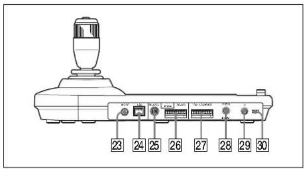
23 MODE selector
Select the position corresponding to the camera to be connected.
| Switch position Camera mode |
| 0 Automatically selected (default) |
| 1 Not used |
| 2 Not used |
| 3 Not used |
| 4 Not used |
| 5 Not used |
| 6 Not used |
| 7 BRC-Z700 |
| 8 BRC-Z330 |
| 9 BRC-H900 |
| A BRC-X1000/H800/H780 |
| B BRC-X400/X401, SRG-X400/201M2/X120/HD1M2 |
| C Not used |
| D Not used |
| E Not used |
| F Not used |
Note
Use positions 7 to 9, A, and B when all the connected cameras are of the same model. In other cases, use position 0.
24 LAN connector (RJ-45 8-pin)
For LAN connection.
Connect a LAN HUB (10BASE-T/100BASE-TX), using a LAN cable (category 5 or higher).
When a link is established, the green indicator lights, and it flashes during communication. While connected with 100BASE-TX, the yellow indicator also lights.
Notes
- For safety, do not connect the connector for peripheral device wiring that might have excessive voltage to this port. Follow the instructions for this port.
- When you connect the LAN cable of the unit to peripheral device, use a shielded-type cable to prevent malfunction due to radiation noise.
25 VISCA RS-232C connector
Connect to the VISCA RS-232C IN connector of the camera or the Optical Multiplex Unit.
26 VISCA RS-422 connector
Connect to the VISCA RS-422 connector of the camera or the Optical Multiplex Unit. An RS-422 connector plug is attached at the factory.
27 TALLY/CONTACT connector
This connector is used for the tally lamp input or the contact output. Select the function of this connector using the DIP switch on the bottom of the unit. You can use the factory fitted RS-422 connector plug for this connector.
28DC IN 12V connector
Connect the supplied AC power adaptor.
29 (power) switch
Press this switch to turn on/off this unit.
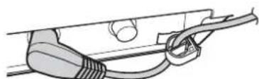
30 Cord clamper
Fixes the cord of the AC power adaptor.
- Release the lock of the cord clamper.
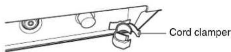
- Connect the supplied AC power adaptor.
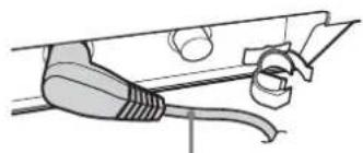
natural_image
Line drawing of a plug inserted into a socket (no text or symbols)Cord of the AC adaptor
- Thread the cord of the AC power adaptor into the cord clamper, then close the lock.
natural_image
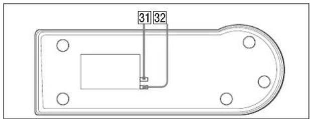
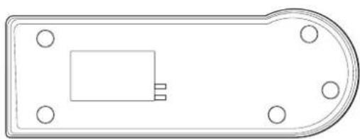
Diagram of a cable being inserted into a connector (no text or symbols present)Bottom
Notes
- The Mac address is printed on the bottom of the IP remote controller.
- Set the switches before you turn on the power of this unit. Otherwise, the setting is not effective (except for DIP 2 switches 1 and 2).
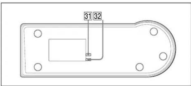
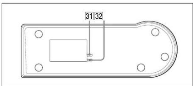
31DIP 1 switch
Switch 1: Serial/LAN connection selector
Selects the communication method. Set ON for serial connection, or OFF for LAN connection.
Switch 2: RS-232C/RS-422 selector
Selects the RS-232C or RS-422 when DIP 1 switch 1 is set to ON.
Set to ON for RS-422, or OFF for RS-232C.
Switch 3: Communication baud rate selector
Selects the communication baud rate for RS-232C/RS-422.
Set to ON for 38,400 bps, or OFF for 9,600 bps.
Switch 4, 5: TALLY/CONTACT switch
Selects the function of the TALLY/CONTACT connector.
You can select the following functions.
| Switch4 | Switch5 | Mode |
OFF OFF NORMAL TALLY mode:
The following actions are performed for the number that is input from the TALLY/CONTACT connector only while receiving the commands.
- The selected camera switches to the camera matching the number of the command from the TALLY/CONTACT connector.
- When the selected camera number matches that of the command from the TALLY/CONTACT connector: The selected camera is not switched, and can continue to be operated.
| Switch 4 | Switch 5 | Mode |
| - When the selected camera does not receive its own number command from the TALLY/CONTACT connector:The selected camera switches to the camera whose number matches that of the command from the TALLY/CONTACT connector.If two or more numbers are received from the TALLY/ CONTACT connector, the camera with the smallest number is selected.You can operate the selected camera after returning the joystick to the neutral position.(If you switch cameras and the camera group number changes, the GROUP/ POSITION button lights up for about 1 second.)The selected CAMERA button will flash in red and yellow alternately.If two or more numbers are received from the TALLY/ CONTACT connector, CAMERA buttons which are not selected will light in red. You can select a camera by pressing its respective CAMERA button (lit in red).The tally lamp of the camera receiving a command from the TALLY/CONTACT connector lights.*Complement:When there are no commands from the TALLY/CONTACT connector, the tally lamp of the selected camera lights.*If commands from the TALLY/CONTACT connector stop, the selected camera is not changed.* I f32DIP 2 switch 5 is set to camera TALLY lamps will not light. |
| Switch4 | Switch5 | Mode |
| ON OFF ON AIR TALLY mode:The following actions are performed for the number that is input from the TALLY/CONTACT connector only while receiving the commands.The corresponding CAMERA button lights in red.A camera can be selected arbitrarily. Selecting a CAMERA button lit in red will make it flash in red and yellow alternately.The tally lamp of the camera receiving a command from the TALLY/CONTACT connector lights.*I f32DIP 2 switch 5 is set to ON, camera TALLY lamps will not light. | ||
| OFF ON CONTACT mode:The camera number that is selected by the unit is output to the connected peripheral device. | ||
| ON ON CONTACT (TALLY) mode:The camera number that is selected by the unit is output to the connected peripheral device and the tally lamp of the selected camera lights.*I f32DIP 2 switch 5 is set to ON, camera TALLY lamps will not light. | ||
Switch 6: COMMAND selector
Switches the signal for the TALLY/CONTACT connector between STD (standard method) and EXPAND (expansion method).
Set ON for EXPAND, OFF for STD.
This setting is not effective for RS-232C/RS-422 (fixed as STD).
STD (standard method)
- When treating the TALLY/CONTACT connector as input:
When one of the terminals 1 to 7 is short-circuited to GND, the corresponding number is accepted. (Two or more numbers can be simultaneously accepted.) - When treating the TALLY/CONTACT connector as output:
Transmits to the external device by earthing one of the terminals 1 to 7.
Tip
When using camera number 8 or higher, use EXPAND.
EXPAND (expansion method)
- When treating the TALLY/CONTACT connector as input:
Treats the terminal 1 to 7 as a binary number. Accepts as number 1 when the terminal 1 is earthed and terminals 2 to 7 is open.
- When treating the TALLY/CONTACT connector as output:
Treats the terminal 1 to 7 as a binary number, and transmits to the external device.
Number 1 is output when the terminal 1 is earthed and terminal 2 to 7 is high.
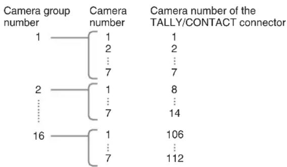
About the camera number that is input/output from the TALLY /CONTACT connector
Relation between total of 112 cameras (assigned to the camera numbers 1 to 7 in each of the camera group numbers 1 to 16) and the camera number of TALLY/CONTACT connector is as follows.
tree
| Camera group number | Camera number | Camera number of the TALLY/CONTACT connector | | :--- | :--- | :--- | | 1 | 1 | 1 | | 2 | 2 | 2 | | ... | ... | ... | | 7 | 7 | 7 | | 2 | 1 | 8 | | ... | ... | ... | | 7 | 7 | 14 | | 16 | 1 | 106 | | ... | ... | ... | | 7 | 7 | 112 |Switch 7, 8: LOCK button function selector
The lock has the following two functions.
①Controls and focus lock: The VALUE/R, BRIGHT/B, and FOCUS controls and AUTO/MANUAL button cannot be operated.
②Joystick lock: The joystick (slanting, dial on the upper part (zoom), button on the top), MENU button, and PAN-TILT RESET button cannot be operated.
You can select the functions that are locked by using the following settings.
| Switch7 | Switch8 | Setting |
| OFF OFF Setting 1: Each time you press the LOCK button, the lock function changes as follows: “1” ↔ unlocked | ||
| ON OFF Setting 2: Each time you press the LOCK button, the lock function changes as follows: “2” ↔ unlocked | ||
| OFF ON Setting 3: Each time you press the LOCK button, the lock function changes as follows: “1 and 2” ↔ unlocked | ||
| Switch7 | Switch8 | Setting |
| ON ON Setting 4: Each time you press the LOCK button, the lock function changes as follows: “1” → “2” → “1 and 2” → unlocked → “1” → ... | ||
32DIP 2 switch
Switch 1: PANEL LIGHT switch
Turns the PANEL button lighting on or off.
Set ON (the GROUP/POSITION and CAMERA buttons light in green), or OFF.
This switch setting is valid even if you change the setting while the power is turned on.
Switch 2: L/R DIRECTION selector
You can reverse the joystick direction.
Set to ON for the reverse operation, or OFF for the standard operation.
For the standard operation, the camera is preset to face toward the right (left) when the joystick is inclined to the right (left). For the reverse operation, the camera is preset to face toward the right (left) when the joystick is inclined to the left (right).
This switch setting is valid even if you change the setting while the power is turned on.
Switch 3: BRIGHT control function selector
Selects the function of the BRIGHT control.
Set to ON for IRIS and GAIN adjustments, or OFF for IRIS adjustment only.
Switch 4: ALL POSITION setting switch
The ALL POSITION function allows you to set the all cameras in the camera groups 15 and 16 to the same preset setting when you load the preset setting to just one camera in group 15 or 16. (Since preset setting is performed for 14 cameras sequentially, they cannot be started simultaneously.)
Set to ON to activate this function, OFF to turn this function off.
This function works only for the LAN connection.
Switch 5 to 7: Expansion switch
Set to OFF.
Complement:
Setting switch 5 to ON prevents the TALLY lamp of the camera from lighting in NORMAL TALLY, ON AIR TALLY or CONTACT (TALLY) mode.
Switch 8: Setting update mode switch
Set to ON to active the setting update mode. When set to ON, you can set and change the camera table from the setting software “RM-IP Setup Tool,” and check the firmware version of the unit.
Once the firmware version verification or camera table re-write is done, make sure to set to OFF to use.
Connections and Operations
Connections
This section focuses on the connection examples for the BRC-H900 camera. For connections with other cameras, refer to the Operating Instructions supplied with the camera you will connect.
Select the IP, RS-232C, or RS-422 connection.* You cannot use multiple communication methods simultaneously.
* SRG-120DH/121DH/120DU/120DS/HD1 are not compatible with the RS-422 connection. SRG-300SE/301SE/201SE/360SHE/280SHE, BRC-X1000/H800/H780/X400/X401, or SRG-X400/201M2/X120/HD1M2 are not compatible with the RS-232C connection. BRC-H900/Z700/Z330 or SRG-300H/301H are compatible with the RS-232C/RS-422 connection.
Connecting cameras that are compatible with IP connection
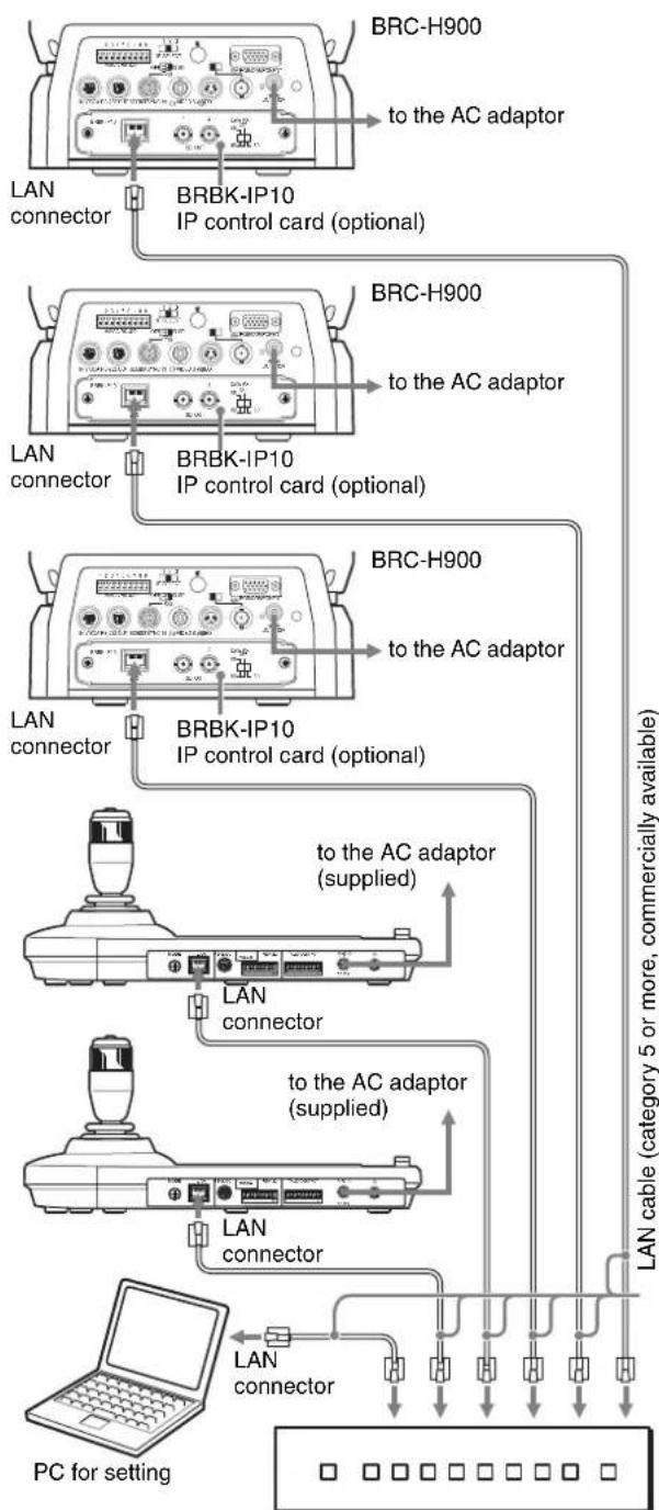
IP connection of cameras, IP remote controllers, and PC
1 Connect the LAN connectors of the unit(s) and camera(s) that are compatible with IP connection by using a LAN cable.
You can connect up to 112 cameras and five IP remote controllers on the same network.
Note
When you connect the LAN cable of the unit to a peripheral device, use a shielded-type cable to prevent malfunction that may result from radiation noise.
2 Connect the PC for the IP setting on the same network.
- Use a LAN cable (category 5 or higher).
- Connect the cameras, IP remote controllers, and PC via a commercially available switching hub (10BASE-T/100BASE-TX). Using on a line of a packet loss or delay may cause a malfunction. Use a high quality network.
-
Do not mix 10BASE-T and 100BASE-TX in the network.
-
The IP address is set at the factory to 192.168.0.10 for RM-IP10, and 192.168.0.100 for BRBK-IP10/BRBK-IP7Z.
- Network delay happens when stacking the switching hubs. We recommend that stacked switching hubs are limited to two.
- When connecting the LAN connectors of the IP remote controller and camera directly without using a switching hub, use a LAN crossover cable.
- Camera number 1 of camera group number 1 is selected and its IP address is set to 192.168.0.100 at the factory.
Notes
- Do not connect more than 112 cameras, five IP remote controllers, and one PC for IP setting, even if controlling a camera that is on a network of a different segment via a router. If you connect more than this or different types of network equipment, problems may occur, such as delay or IP addresses are not set because of IP address duplication.
- If you perform the setting from multiple PCs by using the setting software “RM-IP Setup Tool,” the setting may not be made correctly. Perform the setting from one PC.
- Set the PC so that only the network that you use is enabled.
- Cameras and IP remote controllers cannot be connected to the public network.
3 Connect the camera and IP remote controller to AC outlets by using the supplied AC adaptors and AC power cords.
The camera will automatically pan and tilt, and reset to the position stored in position 1 (Pan/tilt reset action).
Note
Set DIP1 switch 1 to OFF for IP connection (page 9).
Connecting example Default settings for the IP connection
flowchart
graph TD
    A["BRC-H900"] -->|to the AC adaptor| B["IP control card (optional)"]
    C["BRC-H900"] -->|to the AC adaptor| D["IP control card (optional)"]
    E["BRC-H900"] -->|to the AC adaptor| F["IP control card (optional)"]
    G["BRC-H900"] -->|to the AC adaptor| H["IP control card (optional)"]
    I["BRC-H900"] -->|to the AC adaptor| J["IP control card (optional)"]
    K["BRC-H900"] -->|to the AC adaptor| L["IP control card (optional)"]
    M["BRC-H900"] -->|to the AC adaptor| N["IP control card (optional)"]
    O["BRC-H900"] -->|to the AC adaptor| P["IP control card (optional)"]
    Q["BRC-H900"] -->|to the AC adaptor| R["IP control card (optional)"]
    S["BRC-H900"] -->|to the AC adaptor| T["IP control card (optional)"]
    U["BRC-H900"] -->|to the AC adaptor| V["IP control card (optional)"]
    W["BRC-H900"] -->|to the AC adaptor| X["IP control card (optional)"]
    Y["BRC-H900"] -->|to the AC adaptor| Z["IP control card (optional)"]
    AA["BRC-H900"] -->|to the AC adaptor| AB["IP control card (optional)"]
    AC["BRC-H900"] -->|to the AC adaptor| AC
    AD["BRC-H900"] -->|to the AC adaptor| AE["IP control card (optional)"]
    AF["BRC-H900"] -->|to the AC adaptor| AG["IP control card (optional)"]
    AH["BRC-H900"] -->|to the AC adaptor| AI["IP control card (optional)"]
    AJ["BRC-H900"] -->|to the AC adaptor| AK["IP control card (optional)"]
    AL["BRC-H900"] -->|to the AC adaptor| AM["IP control card (optional)"]
    AN["BRC-H900"] -->|to the AC adaptor| AO["IP control card (optional)"]
    AP["BRC-H900"] -->|to the AC adaptor| AQ["IP control card (optional)"]
    AR["BRC-H900"] -->|to the AC adaptor| AS["IP control card (optional)"]
    AT["BRC-H900"] -->|to the AC adaptor| AU["IP control card (optional)"]
    AV["BRC-H900"] -->|to the AC adaptor| AW["IP control card (optional)"]
    AX["BRC-H900"] -->|to the AC adaptor| AY["IP control card (optional)"]
    AZ["BRC-H900"] -->|to the AC adaptor| BA["IP control card (optional)"]
    BB["BRC-H900"] -->|to the AC adaptor| BC["IP control card (optional)"]
    BD["BRC-H900"] -->|to the AC adaptor| CA["IP control card (optional)"]
    CB["BRC-H900"] -->|to the AC adaptor| DA["IP control card (optional)"]
    DB["BRC-H900"] -->|to the AC adaptor| AE["IP control card (optional)"]
    AF["BRC-H900"] -->|to the AC adaptor| AF
    AG["BRC-H900"] -->|to the AC adaptor| AH["IP control card (optional)"]
    AI["BRC-H900"] -->|to the AC adaptor| AI
    AJ["BRC-H900"] -->|to the AC adaptor| AJ
    AK["BRC-H900"] -->|to the AC adaptor| AK
    AL["BRC-H900"] -->|to the AC adaptor| AL
    AM["BRC-H900"] -->|to the AC adaptor| AN["IP control card (optional)"]
    AO["BRC-H900"] -->|to the AC adaptor| AO
    AP["BRC-H900"] -->|to the AC adaptor| AP
    AQ["BRC-H900"] -->|to the AC adaptor| AQ
    AR["BRC-H900"] -->|to the AC adaptor| AR
    AS["BRC-H900"] -->|to the AC adaptor| AS
    AT["BRC-H900"] -->|to the AC adaptor| AT
    AU["BRC-H900"] -->|to the AC adaptor| AU
    AV["BRC-H900"] -->|to the AC adaptor| AV
    AW["BRC-H900"] -->|to the AC adaptor| AW
    AX["AIR"] --> AX
    AY["AIR"] --> AY
    AZ["AIR"] --> AZ
    AA["AIR"] --> AA
    AB["AIR"] --> AB
    AC["AIR"] --> AC
    AD["AIR"] --> AD
    AE["AIR"] --> AE
    AF["AIR"] --> AF
    AG["AIR"] --> AG
    AH["AIR"] --> AH
    AI["AIR"] --> AI
    AJ["AIR"] --> AJ
    AK["AIR"] --> AK
    AL["AIR"] --> AL
    AM["AIR"] --> AM
    AN["AIR"] --> AN
    AO["AIR"] --> AO
    AP["AIR"] --> AP
    AQ["AIR"] --> AQ
    AS["AIR"] --> AS
    AT["AIR"] --> AT
    AU["AIR"] --> AU
    AV["AIR"] --> AV
    AW["AIR"] --> AW
    AX["AIR"] --> AX
    AY["AIR"] --> AY
    AZ["AIR"] --> AZ
    AA["AIR"] --> AA
    AB["AIR"] --> AB
    AT["AIR"] --> AT
    AU["AIR"] --> AU
    AV["AIR"] --> AV
    AX["AIR"] --> AX
    AY["AIR"] --> AY
    AZ["AIR"] --> AZ
    AA["AIR"] --> AA
    AO["AIR"] --> AO
Switching hub (10BASE-T/100BASE-TX, commercially available)
1 Set the DIP 2 switch 8 to ON to perform settings of cameras and IP remote controllers (Setting update mode). Then turn the unit on by pressing the ⏻ switch.
The GROUP/POSITION and CAMERA buttons flash in green while the unit is in the setting update mode.
Notes
- Keep all the cameras and IP remote controllers turned on while setting. Do not turn off any camera or IP remote controller while setting.
- When turning on the unit, do not touch the joystick until the GROUP/POSITION and CAMERA buttons start flashing in green (for detecting an origin point).
- When turning on the unit, do not operate the unit until the GROUP/POSITION and CAMERA buttons start flashing in green.
When you use the signal of the TALLY/CONTACT connector in the NORMAL TALLY mode, the selected camera may be changed by this signal. To prevent this, remove the connection of the TALLY/CONTACT connector or set to the ON AIR TALLY mode.
2 Perform the following settings from the PC by using the setting software "RM-IP Setup Tool." For details on the settings, refer to the "RM-IP Setup Tool guide."
Note
Until about 35 seconds after a camera turns on or is rebooted, settings cannot be changed.
- Set the IP address* and name of the IP remote controller
- Assign each camera to a camera number (CAMERA button), and the camera group number (GROUP/POSITION button) that the camera number belongs to (7 camera numbers in each of 16 camera group numbers, a total of up to 112 cameras). (Camera table setting)**
* If there is a different segment, connect the PC to that segment and perform the settings. If you do not use a gateway, set "Gateway address" to 0.0.0.0.
**To assign a camera of a different segment, use the Export function of "RM-IP Setup Tool."
- Create a "Camera List" csv file for each segment.
-
Create a "Camera Table" csv file for the IP remote controller that you want to assign.
-
Open all the csv files that you created with a text editor, then add the required information to "Camera Table" from "Camera List."
- Import the created "Camera Table" to the IP remote controller by using the Import function.
"Unknown camera is assigned." is displayed on "RM-IP Setup Tool" for devices with different segments.
After setting the camera table, make sure that the relation between the camera and the corresponding camera number and camera group number, by operating with the joystick.* If not correct, set the camera table again by using the setting software "RM-IP Setup Tool."
* When the IP remote controller is moved to the different segment, make sure that “Gateway address” is changed.
To select camera group number
Press any GROUP/POSITION button while holding down the SELECT button. (For selecting 9 to 16, select the camera group number while holding down the SHIFT button.)
To select camera number
Press any CAMERA button.
Note
The GROUP/POSITION and CAMERA buttons flash and stop flashing (up to four times) while updating the IP address, name, and the camera table. Do not turn the IP remote controller off for at least 30 seconds. While in this status, do not operate the unit (especially the joystick, which will be detecting an origin point).
3
After completing the settings, turn off the camera, IP remote controller, and PC, then set DIP 2 switch 8 to OFF.
Tip
While the unit is in setting update mode, you can easily check the firmware version of the unit. The firmware version can be checked with the button where the GROUP/POSITION button lights in yellow while holding down the LOCK button. Refer to the RM-IP Setup Tool for the detailed firmware version No.
(You can also use the LOCK button to check the firmware version in setting update mode.)
Connecting cameras equipped with VISCA RS-232C connector
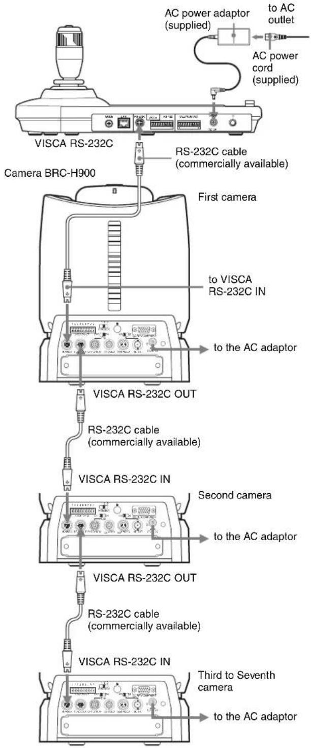
Connections with the VISCA RS-232C cables (cross type) enable control of up to seven cameras with a single RM-IP10 IP Remote Controller. (An RS-232C cable should be used up to 15 m (49.2 feet).)
Note
When connecting with the VISCA RS-232C connector, make sure that DIP 1 switch 1 is set to ON, and DIP 1 switch 2 is set to OFF (page 9).
To assign camera addresses
Before operating, you must assign the camera addresses to the connected cameras as follows. Then you can switch to the camera to be controlled simply by pressing the corresponding CAMERA button.
1 Turn on the power of all the connected cameras and this unit.
2 Hold down the RESET button and press the POWER button on this unit.
The unit recognizes the connected cameras and assigns them camera addresses 1 to 7 automatically in the connected order.
3 Press the POWER button on this unit and check that the CAMERA buttons light.
The number of the lit CAMERA buttons indicates how many cameras have the addresses assigned. Now you can switch to the camera you want to control by pressing the CAMERA button.
Connecting cameras equipped with VISCA RS-422 connector
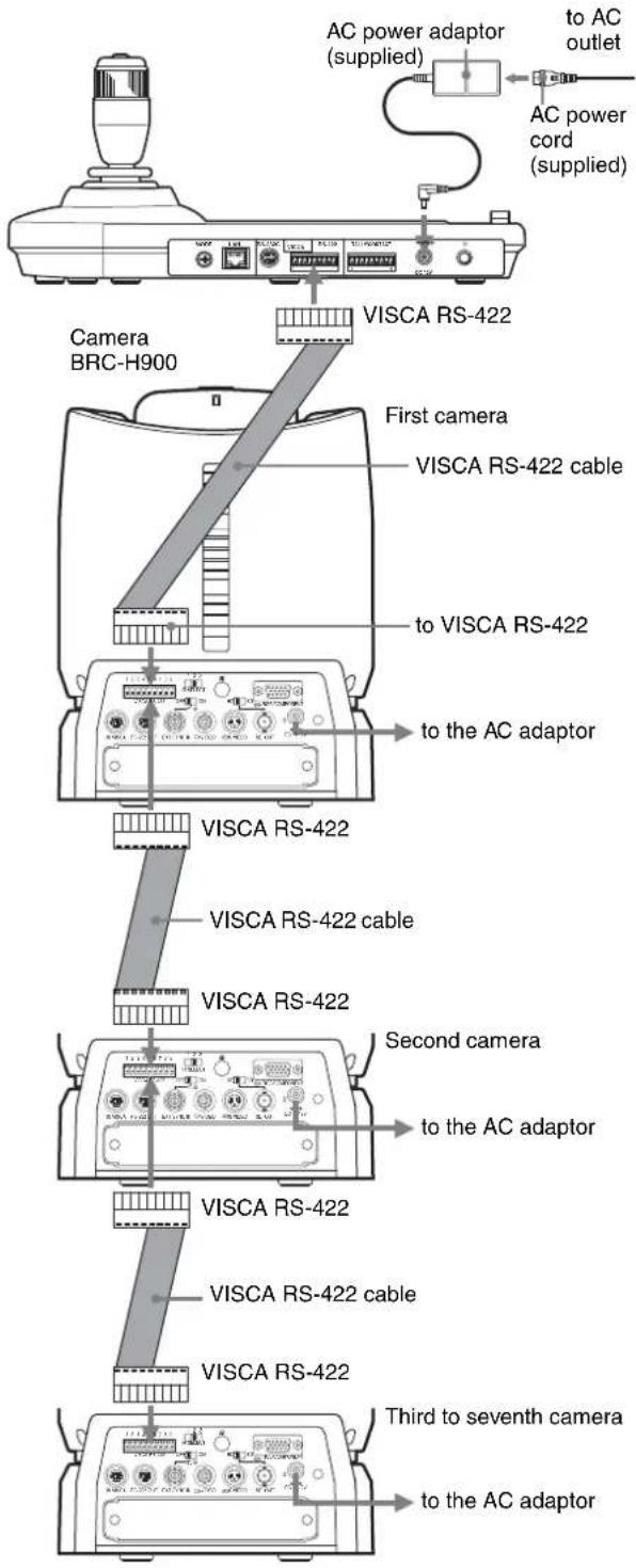
Connection via VISCA RS-422 connectors enables control of multiple cameras. This allows the connection up to 1,200 m (3,937 feet) away.
Prepare the connecting cable using the RS-422 connector plug that comes with this unit.
For making the cable, refer to the pin assignments of the VISCA RS-422 connector (page 24).
For the use of the RS-422 connector plugs, see page 25.
Notes
- When connecting with the VISCA RS-422 connector, make sure that DIP 1 switch 1 is set to ON, and DIP 1 switch 2 is set to ON (page 9).
- When the connections using the VISCA RS-422 connectors are made, the VISCA RS-232C connection is not available.
Connecting the BRU-SF10 Optical Multiplex Unit
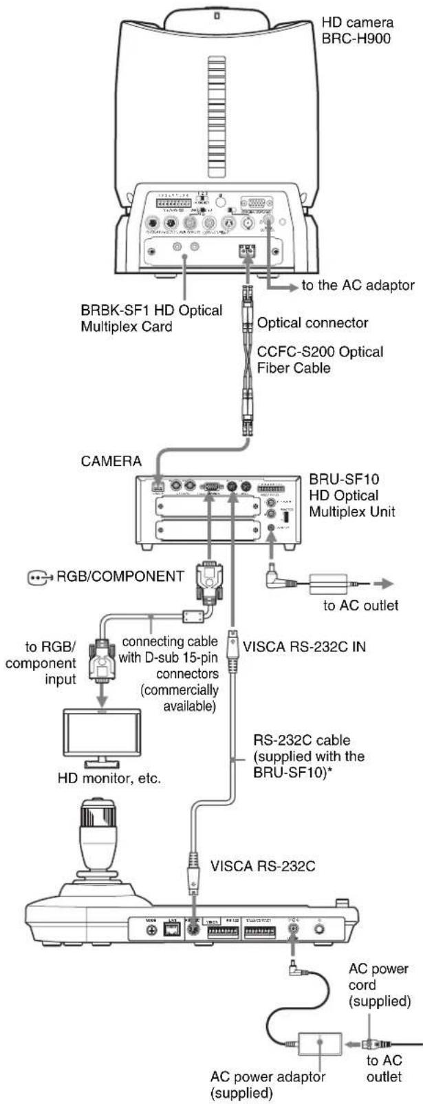
You can control the camera using this unit via the BRU-SF10 Optical Multiplex Unit (not supplied).
flowchart
graph TD
    A["HD camera BRC-H900"] -->|BRBK-SF1 HD Optical Multiplex Card| B["BRU-SF10 HD Optical Multiplex Unit"]
    B -->|to AC outlet| C["VISCA RS-232C IN"]
    C -->|RS-232C cable (supplied with the BRU-SF10)*| D["VISCA RS-232C"]
    D -->|AC power cord (supplied)| E["AC power adaptor (supplied)"]
    E -->|to AC outlet| F["BRB-KSF1 HD Optical Multiplex Card"]
    F -->|to the AC adaptor| G["Optical connector CCFC-S200 Optical Fiber Cable"]
    G -->|to RGB/COMPONENT| H["to RGB/component input"]
    H --> I["connecting cable with D-sub 15-pin connectors (commercially available)"]
    I --> J["HD monitor, etc."]
* The VISCA RS-422 connection is also available if you use the VISCA RS-422 connectors.
For other cameras, you can also use a matching Optical Multiplex Unit to control the camera with this unit. For details on connection, refer to the Operating Instructions supplied with your camera.
Notes
- When using the VISCA RS-232C connectors or VISCA RS-422 connectors, check the VISCA FUNCTION switch on the rear of the Optical Multiplex Unit and the DIP switch on the bottom of this unit (page 9) are set correctly.
- The BRU-SF10 and BRU-H700 Optical Multiplex Units are not compatible with the IP connection. Use them for the RS-232C or RS-422 connection only.
Connecting a video switcher
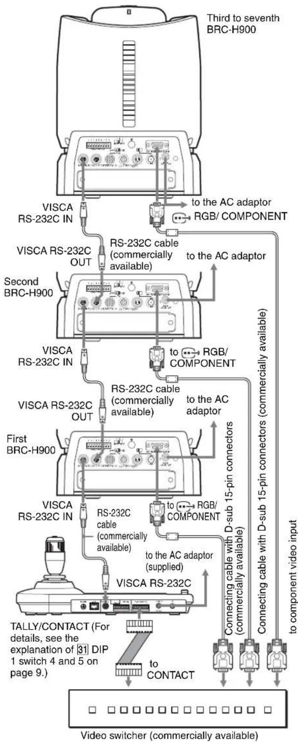
Use a commercially available contact-control type video switcher to switch between the multiple camera signals to be output.
flowchart
graph TD
    A["Third to seventh BRC-H900"] -->|to the AC adaptor RGB/ COMPONENT| B["RS-232C IN"]
    A -->|to the AC adaptor RGB/ COMPONENT| C["RS-232C OUT"]
    A -->|to the AC adaptor RGB/ COMPONENT| D["Second BRC-H900"]
    A -->|to the AC adaptor RGB/ COMPONENT| E["First BRC-H900"]
    A -->|to the AC adaptor RGB/ COMPONENT| F["RS-232C IN"]
    A -->|to the AC adaptor RGB/ COMPONENT| G["RS-232C OUT"]
    A -->|to the AC adaptor RGB/ COMPONENT| H["RS-232C OUT"]
    A -->|to the AC adaptor RGB/ COMPONENT| I["RS-232C OUT"]
    A -->|to the AC adaptor RGB/ COMPONENT| J["RS-232C OUT"]
    A -->|to the AC adaptor RGB/ COMPONENT| K["RS-232C OUT"]
    A -->|to the AC adaptor RGB/ COMPONENT| L["RS-232C OUT"]
    A -->|to the AC adaptor RGB/ COMPONENT| M["RS-232C OUT"]
    A -->|to the AC adaptor RGB/ COMPONENT| N["RS-232C OUT"]
    A -->|to the AC adaptor RGB/ COMPONENT| O["RS-232C OUT"]
    A -->|to the AC adaptor RGB/ COMPONENT| P["RS-232C OUT"]
    A -->|to the AC adaptor RGB/ COMPONENT| Q["RS-232C OUT"]
    A -->|to the AC adaptor RGB/ COMPONENT| R["RS-232C OUT"]
    A -->|to the AC adaptor RGB/ COMPONENT| S["RS-232C OUT"]
    A -->|to the AC adaptor RGB/ COMPONENT| T["RS-232C OUT"]
    A -->|to the AC adaptor RGB/ COMPONENT| U["RS-232C OUT"]
    A -->|to the AC adaptor RGB/ COMPONENT| V["RS-232C OUT"]
    A -->|to the AC adaptor RGB/ COMPONENT| W["RS-232C OUT"]
    A -->|to the AC adaptor RGB/ COMPONENT| X["RS-232C OUT"]
    A -->|to the AC adaptor RGB/ COMPONENT| Y["RS-232C OUT"]
    A -->|to the AC adaptor RGB/ COMPONENT| Z["RS-232C OUT"]
    A -->|to the AC adaptor RGB/ COMPONENT| AA["RS-232C OUT"]
    A -->|to the AC adaptor RGB/ COMPONENT| AB["RS-232C OUT"]
    A -->|to the AC adaptor RGB/ COMPONENT| AC["RS-232C OUT"]
    A -->|to the AC adaptor RGB/ COMPONENT| AD["RS-232C OUT"]
    A -->|to the AC adaptor RGB/ COMPONENT| AE["RS-232C OUT"]
    A -->|to the AC adaptor RGB/ COMPONENT| AF["RS-232C OUT"]
    A -->|to the AC adaptor RGB/ COMPONENT| AG["RS-232C OUT"]
    A -->|to the AC adaptor RGB/ COMPONENT| AH["RS-232C OUT"]
    A -->|to the AC adaptor RGB/ COMPONENT| AI["RS-232C OUT"]
    A -->|to the AC adaptor RGB/ COMPONENT| AJ["RS-232C OUT"]
    A -->|to the AC adaptor RGB/ COMPONENT| AK["RS-232C OUT"]
    A -->|to the AC adaptor RGB/ COMPONENT| AL["RS-232C OUT"]
    A -->|to the AC adaptor RGB/ COMPONENT| AM["RS-232C OUT"]
    A -->|to the AC adaptor RGB/ COMPONENT| AN["RS-232C OUT"]
    A -->|to the AC adaptor RGB/ COMPONENT| AO["RS-232C OUT"]
    A -->|to the AC adaptor RGB/ COMPONENT| AP["RS-232C OUT"]
    A -->|to the AC adaptor RGB/ COMPONENT| AQ["RS-232C OUT"]
    A -->|to the AC adaptor RGB/ COMPONENT| AR["RS-232C OUT"]
    A -->|to the AC adaptor RGB/ COMPONENT| AS["RS-232C OUT"]
    A -->|to the AC adaptor RGB/ COMPONENT| AT["RS-232C OUT"]
    A -->|to the AC adaptor RGB/ COMPONENT| AU["RS-232C OUT"]
    A -->|to the AC adaptor RGB/ COMPONENT| AV["RS-232C OUT"]
    A -->|to the AC adaptor RGB/ COMPONENT| AW["RS-232C OUT"]
    A -->|to the AC adaptor RGB/ COMPONENT| AX["RS-232C OUT"]
    A -->|to the AC adaptor RGB/ COMPONENT| AY["RS-232C OUT"]
    A -->|to the AC adaptor RGB/ COMPONENT| AZ["RS-232C OUT"]
    A -->|to the AC adaptor RGB/ COMPONENT| BA["RS-232C OUT"]
    A -->|to the AC adaptor RGB/ COMPONENT| BB["RS-232C OUT"]
    A -->|to the AC adaptor RGB/ COMPONENT| BC["RS-232C OUT"]
    A -->|to the AC adaptor RGB/ COMPONENT| BD["RS-232C OUT"]
    A -->|to the AC adaptor RGB/ COMPONENT| BE["RS-232C OUT"]
    A -->|to the AC adaptor RGB/ COMPONENT| BF["RS-232C OUT"]
    A -->|to the AC adaptor RGB/ COMPONENT| BG["RS-232C OUT"]
    A -->|to the AC adaptor RGB/ COMPONENT| BH["RS-232C OUT"]
    A -->|to the AC adaptor RGB/ COMPONENT| BI["RS-232C OUT"]
    A -->|to the AC adaptor RGB/ COMPONENT| BJ["RS-232C OUT"]
    A -->|to the AC adaptor RGB/ COMPONENT| BK["RS-232C OUT"]
    A -->|to the AC adaptor RGB/ COMPONENT| BL["RS-232C OUT"]
    A -->|to the AC adaptor RGB/ COMPONENT| BM["RS-232C OUT"]
    A -->|to the AC adaptor RGB/ COMPONENT| BN["RS-232C OUT"]
    A -->|to the AC adaptor RGB/ COMPONENT| BO["RS-232C OUT"]
    A -->|to the AC adaptor RGB/ COMPONENT| BP["RS-232C OUT"]
    A -->|to the AC adaptor RGB/ COMPONENT| BQ["RS-232C OUT"]
    A -->|to the AC adaptor RGB/ COMPONENT| BR["RS-232C OUT"]
    A -->|to the AC adaptor RGB/ COMPONENT| BS["RS-232C OUT"]
    A -->|to the AC adaptor RGB/ COMPONENT| BT["RS-232C OUT"]
    A -->|to the AC adaptor RGB/ COMPONENT| BU["RS-232C OUT"]
    A -->|to the AC adaptor RGB/ COMPONENT| BV["RS-232C OUT"]
    A -->|to the AC adaptor RGB/ COMPONENT| BW["RS-232C OUT"]
For connection with a video switcher, refer to the Operating Instructions of the switcher.
Turning on the Power
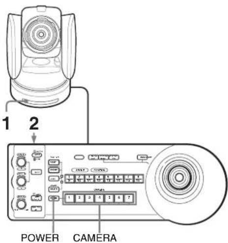
1 Connect the camera to an AC outlet.
The power of the camera is turned on and the POWER lamp lights.
The camera will automatically pan, tilt, and be reset to the position stored in POSITION 1 (Pan/tilt reset action).
2 Press the ⏻ switch on the unit to turn it on.
When the unit is turned on, buttons and indicators flash as follows:
Yellow (1 second) → Green (1 second) → Red (1 second) → The GROUP/POSITION button that was selected when the unit was turned off last (with the upper or lower indicator beside of the SHIFT button and GROUP indicator) and the CAMERA button (2 seconds)
Then, the CAMERA button representing the camera whose power was turned off last, lights.
(CAMERA 1 button lights by default.)
When connecting over a LAN, the unit starts with the last camera group is selected.
3 Turn on the peripheral devices.
Notes
- Be sure to turn on the power of the camera before the power of this unit. Otherwise, the unit cannot recognize the connected camera.
- Do not touch the joystick when turning on the power of the unit. Doing so may affect the confirmation of the origin.
To turn on/off the camera using this unit
As long as the camera is connected to an AC outlet, you can turn the camera on or off with the POWER button on this unit.
While holding down the POWER button, press the CAMERA button corresponding to the camera whose power you want to turn on/off.
When you turn the power off using this unit, the POWER lamp turns off and the STANDBY lamp lights on the camera.
Storing the Camera Settings in Memory
- Presetting Feature
Up to sixteen combinations of settings (sixteen positions), including camera position, zooming, focusing, and backlighting, can be stored in the memory of the camera using this unit.
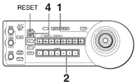
1 Press the PAN-TILT RESET button to reset the pan/tilt position.
2 Press the CAMERA button to select the camera whose settings you want to preset.
To change camera group number (for IP connection)
Press any GROUP/POSITION button while holding down the SELECT button. (For selecting 9 to 16, select the camera group number while holding down the SHIFT button.)
3 Adjust the position, zooming, focusing and backlighting of the camera.
4 While holding down the PRESET button (for POSITION 1 to 8) or the SHIFT and PRESET buttons (for POSITION 9 to 16), press the GROUP/POSITION button in which you want to store the settings.
While holding down (for POSITION 1 to 8)
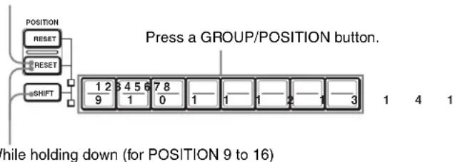
The settings are stored in the memory of the camera.
The pressed button flashes during storing. Flashing stops when storing is completed.
We recommend that you check the stored settings by recalling the preset.
To recall the stored settings
Press the GROUP/POSITION button in which you have stored the settings.
For POSITION 9 to 16, hold down the SHIFT button then press the GROUP/POSITION button.
Tip
To cancel preset recall of the camera, hold down the RESET button, then press the PRESET button.
To cancel the preset memory
While holding down the RESET button (for POSITION 1 to 8) or the SHIFT and RESET buttons (for POSITION 9 to 16), press the GROUP/POSITION button from which you want to cancel the settings.
While holding down (for POSITION 1 to 8)
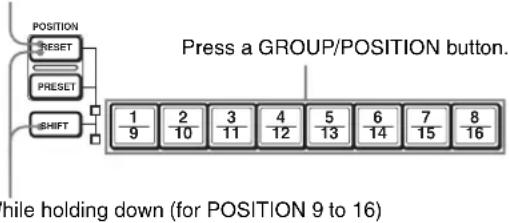
The pressed button flashes during canceling of the settings. Flashing stops when the settings have been canceled.
Notes
- When the power is turned on, the camera starts with the settings stored in POSITION 1.
- If you want to retain the previous pan and tilt positions when the power is turned off and turned on again, store those positions in POSITION 1.
- When you are storing or canceling the settings in one POSITION, you cannot call up, store or cancel the settings in another POSITION.
Setting the speed of the camera moving to a preset position\*
* The moving speed is stored in the internal memory of the camera.
You can select the panning/tilting speed when the camera moves to a preset position.
1 Press the CAMERA button to select the camera whose speed you want to set.
To change camera group number (for IP connection)
Press any GROUP/POSITION button while holding down the SELECT button. (For selecting 9 to 16, select the camera group number while holding down the SHIFT button.)
2 Press the GROUP/POSITION button for which you want to set the speed for more than one second. All the CAMERA buttons, 1 to 7, flash.
3 Press one of the CAMERA buttons to select the speed.
| CAMERA button | VISCA value*1 | Panning/tilting speed(Unit: degree/sec.) | |
| BRC-Z700, BRC-H900 | BRC-Z330 | ||
| 1 04h (4) 1 1.3 | |||
| 2 | 0 | A | h( |
| 3 | 0 | D | h( |
| 4 10h (16) | 11 | 11.6 | |
| 5 13h (19) | 23.3 | 23.9 | |
| 6 16h (22) | 43 | 43.4 | |
| 7 18h (24) | 19h (25)*2 (default) | 60 (default) | 60 (default) |
*1 For details on the setting of models which are not mentioned above, refer to the VISCA value of each model's command list.
*2 When BRC-X400/X401 or SRG-X400/201M2/X1 is connected.
Note
For SRG-360SHE, SRG-300SE, SRG-300H, SRG-120DH, SRG-120DU and SRG-120DS, you cannot set the speed when the camera moves to the position. The camera always moves in maximum speed.
Now the camera will move to the position preset to the pressed GROUP/POSITION button with the selected speed.
To set the speed of the camera moving to a preset position between 9 and 16
To set the speed of the camera moving to a preset position between 9 and 16, hold down the SHIFT button and press the corresponding GROUP/POSITION button.
Using the Function Stored in the Memory of the RM-IP10
The following function for panning/tilting operations with the RM-IP10 is stored in the memory of this unit.
Setting a limit on the maximum panning/tilting speed
You can limit the panning/tilting speed obtained when you incline the joystick at the maximum angle.
1 Hold the PAN-TILT RESET button for more than a second while pressing the SHIFT button. All of the CAMERA buttons 1 to 7 flash.
2 Press the CAMERA button corresponding to the speed you want to set, as shown in the table below.
| CAMERA button | VISCA value* | Maximum panning/tilting speed(Unit: degree/sec.) | |
| BRC-Z700, BRC-H900 | |||
| 1 0Ch (12) | 3.5 4.4 | ||
| 2 0Eh (14) | 6.4 6.7 | ||
| 3 10h (16) | 11 11.6 | ||
| 4 12h (18) | 18.3 18.6 | ||
| 5 14h (20) | 29 29.2 | ||
| 6 16h (22) | 43 43.4 | ||
| 7 18h (24) | 60 60 | ||
* For details on the setting of models which are not mentioned above, refer to the VISCA value of each model's command list.
Only the CAMERA button you pressed flashes, and the corresponding maximum panning/tilting speed is set.
Note
If you use another RM-IP10 or you connect another camera to this unit, set a limit on the maximum panning/tilting speed again.
To Return to the Factory Setting
1 Turn the unit on while holding down the RESET and SELECT buttons.
When the unit is turned on, buttons and indicators flash as follows:
Yellow (1 second) → Green (1 second) → Red (1 second) → The GROUP/POSITION button that was selected when the unit was turned off last (with the upper or lower indicator beside of the SHIFT button and GROUP indicator) and the CAMERA button (2 seconds)
2 When the GROUP/POSITION and CAMERA buttons flash in green, release the RESET and SELECT buttons, then turn the unit off by pressing the ⏻ button.
When the unit is turned on next time, the unit will start with its factory settings.
Factory settings
- IP address of the IP remote controller: 192.168.0.10
- Subnet mask of the IP remote controller: 255.255.255.0
- Default gateway of the IP remote controller: 0.0.0.0
- Name of the IP remote controller: CTL1
- A camera IP address of 192.168.0.100 is assigned to the camera number 1 of the camera group number 1. No other IP addresses are assigned to any of the other camera numbers or camera group numbers.
- The unit starts with camera number 1 of camera group number 1 selected.
- LOCK button: The lock function is not activated.
Appendix
Troubleshooting
Before bringing in your unit for service, check the following as a guide to troubleshoot the problem. If the problem cannot be corrected, consult with your Sony dealer.
| Symptom Cause Remedy | ||
| The power of the unit is not turned on. The AC power adaptor is not connected to the DC IN 12V jack firmly. | Insert the power cord firmly as far as it will go. | |
| The AC power cord is not inserted firmly into the AC power adaptor or the AC outlet. | Insert the power cord firmly as far as it will go. | |
| The camera cannot be operated with the unit. | Communication setting is not correct. Select the proper setting with the DIP switch on the bottom of the unit (page 9). Select one of the LAN, RS-232C, and RS-422 connection. | |
| The communication baud rate setting of the camera and the unit differ. (When connecting with RS-232C/RS-422.) | Select the communication baud rate, 9,600 bps or 38,400 bps, with the DIP switch on the unit (page 9) which is selected on the camera. | |
| The connection using the VISCA RS-422 connectors is not correctly made. (When connecting with RS-422.) | Check that the connection to the VISCA RS-422 connectors is correctly made, and the RS-422 cable is properly connected. | |
| The unit cannot be operated at all. | — | Pull out the plug of the power cord from the AC outlet, then reinsert it into the AC outlet after a while. |
| The IP remote controller setting cannot be changed from the setting software “RM-IP Setup Tool.” | The IP remote controller is not set to the setting update mode. | Set the IP remote controller to the setting update mode by using the DIP switch on the bottom of the unit (page 9). |
| The GROUP/POSITION and CAMERA buttons flash in green. | The IP remote controller is set to the setting update mode. | Cancel the setting update mode by using the DIP switch on the bottom of the unit (page 9). |
| The KNOB/JOYSTICK indicators do not light, or the lighting order is different. | The LOCK button function setting is not correct. | Check the setting of the DIP switch on the bottom of the unit (page 9). |
| The joystick and PAN TILT and MENU buttons cannot be operated. | The LOCK function is on. Cancel the LOCK function by pressing the LOCK button. | |
| The GROUP/POSITION and SELECT buttons cannot be operated. | You are not using the IP connection. These buttons work for the IP connection only. | |
| The camera cannot be operated from the IP remote controller when they are connected to each other directly. | You are not using a LAN crossover cable. Use a LAN crossover cable when making a one-to-one LAN connection. | |
Specifications
Input/output connectors
Control input/output
VISCA RS-232C OUT: Mini DIN 8-pin type
VISCA RS-422: 9-pin type
TALLY IN/CONTACT OUT: 9-pin type
LAN: RJ-45 (8-pin), 10BASE-T/100BASE-TX automatically detected
Control signal format (for RS-232C/RS-422
communication)
9,600 bps/38,400 bps
Data: 8 bit
Stop bit: 1
Power connector
JEITA type4 (DC IN 12V)
Notes
• Always verify that the unit is operating properly before use. SONY WILL NOT BE LIABLE FOR DAMAGES OF ANY KIND INCLUDING, BUT NOT LIMITED TO, COMPENSATION OR REIMBURSEMENT ON ACCOUNT OF THE LOSS OF PRESENT OR PROSPECTIVE PROFITS DUE TO FAILURE OF THIS UNIT, EITHER DURING THE WARRANTY PERIOD OR AFTER EXPIRATION OF THE WARRANTY, OR FOR ANY OTHER REASON WHATSOEVER.
- SONY WILL NOT BE LIABLE FOR CLAIMS OF ANY KIND MADE BY USERS OF THIS UNIT OR MADE BY THIRD PARTIES.
- SONY WILL NOT BE LIABLE FOR THE TERMINATION OR DISCONTINUATION OF ANY SERVICES RELATED TO THIS UNIT THAT MAY RESULT DUE TO CIRCUMSTANCES OF ANY KIND.
General
Input voltage 12 V DC (10.8 to 13.2 V DC)
Current consumption
0.3 A max. (at 12 V DC), 3.6 W
Operating temperature
0^ to 40^ (32°F to 104°F)
Storage temperature
-20^ to +60^ (-4^ to 140^)
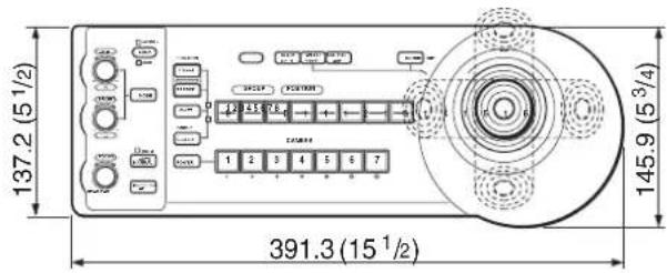
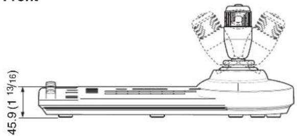
Dimensions 391.3 mm × 165 mm × 145.9 mm
(15^1/2inches × 6^1/2inches × 5^3/_4inches) (w/h/d)
Mass Approx. 950 g (2 lb 15 oz)
Supplied accessories
AC power adaptor (Sony) (1)
AC power cord (1)
RS-422 connector plug (attached to the unit) (2)
Safety Regulations (1)
Design and specifications are subject to change without notice.
Dimensions Pin Assignments
Top
Front
Side
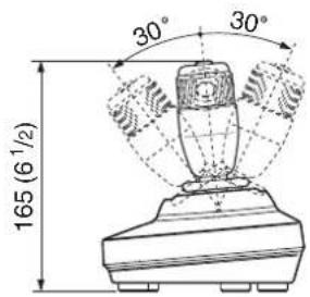
Bottom
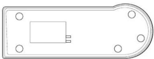
natural_image
Top-down schematic of a remote control panel with a rectangular component and four mounting holes (no text or symbols)Unit: mm (inches)
VISCA RS-232C output connector (mini DIN 8-pin, female)

| Pin No. Function |
| 1 No connection |
| 2 No connection |
| 3 TXD IN |
| 4 GND |
| 5 RXD IN |
| 6 GND |
| 7 No connection |
| 8 No connection |
VISCA RS-422 connector (connector plug, 9-pin)
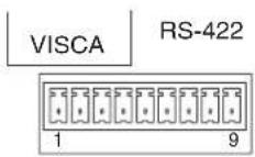
| Pin No. Function |
| 1 No connection |
| 2 No connection |
| 3 No connection |
| 4 No connection |
| 5 GND |
| 6 RXD IN- |
| 7 RXD IN+ |
| 8 TXD IN- |
| 9 TXD IN+ |
TALLY/CONTACT connector (connector plug, 9-pin)
TALLY/CONTACT
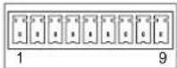
Using the VISCA RS-422 connector plug
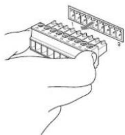
1 Grasp both ends of the VISCA RS-422 connector plug and pull it out as shown in the illustration.
natural_image
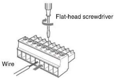
Illustration of hands using a handheld electronic device to interact with a grid of components (no text or symbols visible)2 Insert a wire (AWG Nos. 28 to 18) into the desired wire opening on the plug, and tighten the screw for that wire using a flat-head screwdriver.
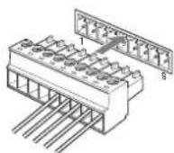
3 Insert the VISCA RS-422 connector plug into the VISCA RS-422 connector.
Notes
- In order to stabilize the voltage level of the signal, connect both ends to GND.
- The maximum connection distance with the VISCA RS-422 connection is approximately 1,200 m (3,937 feet).

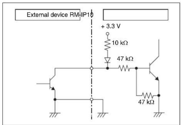
Example connection of TALLY/CONTACT connector for input
Switch or relay connection
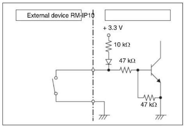
Open collector connection
Example connection of TALLY/CONTACT connector for output
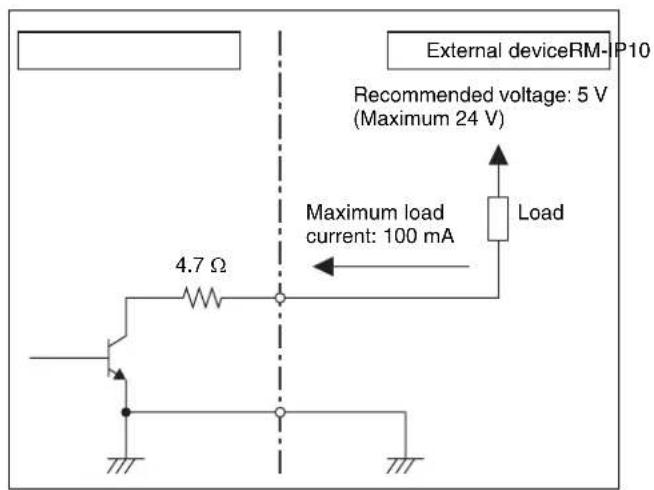
WARNING
If an inrush or reverse voltage that is over the rating is applied to the TALLY/CONTACT connector, it may cause a malfunction, smoke, or fire.
Input Waveform of TALLY/ CONTACT Connector
Approx. 2.7 V (open voltage)
0.2 V or less (closed voltage)
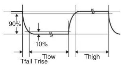
Tfall, Trise: within 5 msec
Tlow, Thigh: 33 msec or more
In the Expand mode, the following can also be applied:
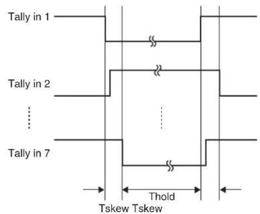
Tskew: within 0.5 msec
Thold: 33 msec or more
License
This software partially supports component uIP. Therefore the following license conditions apply.
Copyright (c) 2001-2006, Adam Dunkels and the Swedish Institute of Computer Science All rights reserved.
Redistribution and use in source and binary forms, with or without modification, are permitted provided that the following conditions are met:
- Redistributions of source code must retain the above copyright notice, this list of conditions and the following disclaimer.
- Redistributions in binary form must reproduce the above copyright notice, this list of conditions and the following disclaimer in the documentation and/or other materials provided with the distribution.
- The name of the author may not be used to endorse or promote products derived from this software without specific prior written permission.
THIS SOFTWARE IS PROVIDED BY THE AUTHOR 'AS IS' AND ANY EXPRESS OR IMPLIED WARRANTIES, INCLUDING, BUT NOT LIMITED TO, THE IMPLIED WARRANTIES OF MERCHANTABILITY AND FITNESS FOR A PARTICULAR PURPOSE ARE DISCLAIMED. IN NO EVENT SHALL THE AUTHOR BE LIABLE FOR ANY DIRECT, INDIRECT, INCIDENTAL, SPECIAL, EXEMPLARY, OR CONSEQUENTIAL DAMAGES (INCLUDING, BUT NOT LIMITED TO, PROCUREMENT OF SUBSTITUTE GOODS OR SERVICES; LOSS OF USE, DATA, OR PROFITS; OR BUSINESS INTERRUPTION) HOWEVER CAUSED AND ON ANY THEORY OF LIABILITY, WHETHER IN CONTRACT, STRICT LIABILITY, OR TORT (INCLUDING NEGLIGENCE OR OTHERWISE) ARISING IN ANY WAY OUT OF THE USE OF THIS SOFTWARE, EVEN IF ADVISED OF THE POSSIBILITY OF SUCH DAMAGE.
natural_image
Line drawing of a plug inserted into a container (no text or symbols)natural_image
Illustration of a cable being inserted into a connector (no text or symbols)Face inférieure
Remarques
Face inférieure
natural_image
Top-down schematic of a remote control panel with a rectangular component and four circular mounting holes (no text or symbols)Unité : mm (pouces)
natural_image
Illustration of hands holding a small electronic component with a ruler above it (no text or symbols visible)Copyright (c) 2001-2006, Adam Dunkels and the Swedish Institute of Computer Science All rights reserved.
Redistribution and use in source and binary forms, with or without modification, are permitted provided that the following conditions are met:
- Redistributions of source code must retain the above copyright notice, this list of conditions and the following disclaimer.
- Redistributions in binary form must reproduce the above copyright notice, this list of conditions and the following disclaimer in the documentation and/or other materials provided with the distribution.
- The name of the author may not be used to endorse or promote products derived from this software without specific prior written permission.
THIS SOFTWARE IS PROVIDED BY THE AUTHOR 'AS IS' AND ANY EXPRESS OR IMPLIED WARRANTIES, INCLUDING, BUT NOT LIMITED TO, THE IMPLIED WARRANTIES OF MERCHANTABILITY AND FITNESS FOR A PARTICULAR PURPOSE ARE DISCLAIMED. IN NO EVENT SHALL THE AUTHOR BE LIABLE FOR ANY DIRECT, INDIRECT, INCIDENTAL, SPECIAL, EXEMPLARY, OR CONSEQUENTIAL DAMAGES (INCLUDING, BUT NOT LIMITED TO, PROCUREMENT OF SUBSTITUTE GOODS OR SERVICES; LOSS OF USE, DATA, OR PROFITS; OR BUSINESS INTERRUPTION) HOWEVER CAUSED AND ON ANY THEORY OF LIABILITY, WHETHER IN CONTRACT, STRICT LIABILITY, OR TORT (INCLUDING NEGLIGENCE OR OTHERWISE) ARISING IN ANY WAY OUT OF THE USE OF THIS SOFTWARE, EVEN IF ADVISED OF THE POSSIBILITY OF SUCH DAMAGE.
27 Conector TALLY/CONTACT
28 Conector DC IN 12V
natural_image
Diagram of a cable connector with a plug and cable (no text or symbols)Parte inferior
Notas
Interruptor 4, 5: interruptor TALLY/CONTACT
OFF OFF Modo NORMAL TALLY:
Interruptor 6: selector COMMAND
Parte inferior
natural_image
Top-down schematic of a remote control panel with a rectangular component and four corner holes (no text or symbols)natural_image
Illustration of hands holding a grid-based electronic component with a ruler above (no text or symbols visible)Tfall, Trise: en 5 ms
Tskew: en 0,5 ms
Thold: 33 ms o más
Licencia
Copyright (c) 2001-2006, Adam Dunkels and the Swedish Institute of Computer Science All rights reserved.
Redistribution and use in source and binary forms, with or without modification, are permitted provided that the following conditions are met:
- Redistributions of source code must retain the above copyright notice, this list of conditions and the following disclaimer.
- Redistributions in binary form must reproduce the above copyright notice, this list of conditions and the following disclaimer in the documentation and/or other materials provided with the distribution.
- The name of the author may not be used to endorse or promote products derived from this software without specific prior written permission.
THIS SOFTWARE IS PROVIDED BY THE AUTHOR 'AS IS' AND ANY EXPRESS OR IMPLIED WARRANTIES, INCLUDING, BUT NOT LIMITED TO, THE IMPLIED WARRANTIES OF MERCHANTABILITY AND FITNESS FOR A PARTICULAR PURPOSE ARE DISCLAIMED. IN NO EVENT SHALL THE AUTHOR BE LIABLE FOR ANY DIRECT, INDIRECT, INCIDENTAL, SPECIAL, EXEMPLARY, OR CONSEQUENTIAL DAMAGES (INCLUDING, BUT NOT LIMITED TO, PROCUREMENT OF SUBSTITUTE GOODS OR SERVICES; LOSS OF USE, DATA, OR PROFITS; OR BUSINESS INTERRUPTION) HOWEVER CAUSED AND ON ANY THEORY OF LIABILITY, WHETHER IN CONTRACT, STRICT LIABILITY, OR TORT (INCLUDING NEGLIGENCE OR OTHERWISE) ARISING IN ANY WAY OUT OF THE USE OF THIS SOFTWARE, EVEN IF ADVISED OF THE POSSIBILITY OF SUCH DAMAGE.
For the customers in the U.S.A.
SONY LIMITED WARRANTY - Please visit http://www.sony.com/psa/warranty for important information and complete terms and conditions of Sony's limited warranty applicable to this product.
For the customers in Canada
SONY LIMITED WARRANTY - Please visit http://www.sonybiz.ca/pro/lang/en/ca/article/resources-warranty for important information and complete terms and conditions of Sony's limited warranty applicable to this product.
For the customers in Europe
Sony Professional Solutions Europe - Standard Warranty and Exceptions on Standard Warranty. Please visit https://pro.sony/en_GB/support-services/warranty/support-professional-solutions-europe-standard-product-warranty for important information and complete terms and conditions.
For the customers in Korea
SONY LIMITED WARRANTY - Please visit http://bpeng.sony.co.kr/handler/BPAS-Start for important information and complete terms and conditions of Sony's limited warranty applicable to this product.
- IP Remote Controller
- Owner's Record
- WARNING
- IMPORTANT
- For the customers in the U.S.A.
- For the customers in Canada
- For the customers in Europe, Australia and New Zealand
- For the customers in Europe
- Connections and Operations
- Appendix
- About the RM-IP Setup Tool
- Data and security
- Getting Started
- Precautions
- Operating or storage location
- Ventilation
- Transportation
- Cleaning
- On moisture condensation
- On parts life expectancy
- Overview
- Features
- Operate up to 112 cameras\* by using the IP connection
- Compatible with VISCA RS-232C/RS-422\*3
- Note
- The optical three-axis joystick allows comfortable pan/tilt/zoom operations.
- Easy operation of versatile camera adjustments
- Preset feature to save camera settings
- Notes
- System requirements for the PC
- Location and Function of Parts
- ① LOCK button and JOYSTICK/KNOB indicators
- VALUE/R control
- When the white balance adjustment mode is selected with the MODE button (with the R indicator lit):
- ③ BRIGHT/B control
- When the brightness adjustment mode is selected with the MODE button (with the BRIGHT indicator lit):
- When the white balance adjustment mode is selected with the MODE button (with the B indicator lit):
- Functions of the VALUE and BRIGHT controls
- Functions of the R and B controls
- MODE button
- FOCUS control
- AUTO/MANUAL button and AUTO indicator
- ONE PUSH AF button
- PRESET button
- RESET button
- 10GROUP indicator
- 11GROUP button
- PAN-TILT RESET button
- ONE PUSH AWB button
- POSITION indicator
- MENU button
- 17Joystick
- Panning and tilting
- Zooming
- To face the camera back to the front
- 18SHIFT button and indicators
- SELECT button
- POWER button
- CAMERA buttons
- GROUP/POSITION buttons
- MODE selector
- LAN connector (RJ-45 8-pin)
- VISCA RS-232C connector
- VISCA RS-422 connector
- TALLY/CONTACT connector
- 28DC IN 12V connector
- (power) switch
- Cord clamper
- Bottom
- 31DIP 1 switch
- Switch 1: Serial/LAN connection selector
- Switch 2: RS-232C/RS-422 selector
- Switch 3: Communication baud rate selector
- Switch 4, 5: TALLY/CONTACT switch
- Switch 6: COMMAND selector
- STD (standard method)
- Tip
- About the camera number that is input/output from the TALLY /CONTACT connector
- Switch 7, 8: LOCK button function selector
- 32DIP 2 switch
- Switch 1: PANEL LIGHT switch
- Switch 2: L/R DIRECTION selector
- Switch 3: BRIGHT control function selector
- Switch 4: ALL POSITION setting switch
- Switch 5 to 7: Expansion switch
- Switch 8: Setting update mode switch
- Connections
- Connecting cameras that are compatible with IP connection
- IP connection of cameras, IP remote controllers, and PC
- Connecting example Default settings for the IP connection
- To select camera group number
- To select camera number
- 3
- Connecting cameras equipped with VISCA RS-232C connector
- To assign camera addresses
- Connecting cameras equipped with VISCA RS-422 connector
- Connecting the BRU-SF10 Optical Multiplex Unit
- Connecting a video switcher
- Turning on the Power
- To turn on/off the camera using this unit
- Storing the Camera Settings in Memory
- - Presetting Feature
- To change camera group number (for IP connection)
- To recall the stored settings
- To cancel the preset memory
- Setting the speed of the camera moving to a preset position\*
- To set the speed of the camera moving to a preset position between 9 and 16
- Using the Function Stored in the Memory of the RM-IP10
- Setting a limit on the maximum panning/tilting speed
- To Return to the Factory Setting
- Turn the unit on while holding down the RESET and SELECT buttons.
- When the GROUP/POSITION and CAMERA buttons flash in green, release the RESET and SELECT buttons, then turn the unit off by pressing the ⏻ button.
- Factory settings
- Troubleshooting
- Specifications
- Input/output connectors
- General
- Supplied accessories
- Dimensions Pin Assignments
- TALLY/CONTACT connector (connector plug, 9-pin)
- Using the VISCA RS-422 connector plug
- Example connection of TALLY/CONTACT connector for input
- Input Waveform of TALLY/ CONTACT Connector
- License
- Remarques
- Conector TALLY/CONTACT
- Conector DC IN 12V
- Notas
- Interruptor 4, 5: interruptor TALLY/CONTACT
- OFF OFF Modo NORMAL TALLY:
- Interruptor 6: selector COMMAND
- Licencia
- For the customers in Korea
Brand : SONY
Model : RM-IP10
Category : Joystick