
Aures Slim - Boiler Ariston Thermo - Free user manual and instructions
Find the device manual for free Aures Slim Ariston Thermo in PDF.


| Product type | Wall-hung condensing boiler |
| Brand | Ariston Thermo |
| Model | Aures Slim |
| Dimensions (H x W x D) | 700 x 400 x 300 mm |
| Weight | 32 kg |
| Power supply | 230 V / 50 Hz |
| Nominal thermal output | 24 kW |
| Fuel | Natural gas (G20) / Propane (G31) |
| Seasonal efficiency | Up to 94% (class A) |
| Main functions | Central heating and instantaneous domestic hot water |
| Flue type | Concentric flue (60/100 mm) |
| Max. operating pressure | 3 bar |
| Hot water flow rate (ΔT 30°C) | 11.5 l/min |
| Sound level | ≤ 50 dB(A) |
| Maintenance and cleaning | Radiator bleeding, annual check by professional, cleaning of the heat exchanger |
| Safety | Anti-overheat safety sensor, 3-way valve, frost protection |
| Spare parts and repairability | Available through Ariston Thermo network; repairability index: 7.5/10 |
| Protection rating | IPX5D |
Frequently Asked Questions - Aures Slim Ariston Thermo
User questions about Aures Slim Ariston Thermo
0 question about this device. Answer the ones you know or ask your own.
Ask a new question about this device
Download the instructions for your Boiler in PDF format for free! Find your manual Aures Slim - Ariston Thermo and take your electronic device back in hand. On this page are published all the documents necessary for the use of your device. Aures Slim by Ariston Thermo.
USER MANUAL Aures Slim Ariston Thermo
Electric Tankless Water Heaters
This manual must only be used by a qualified installer / service technician. Read all instructions in this manual before installing. Perform steps in the given order. Failure to do so could result in substantial property damage, severe personal injury, or death.
California Proposition 65 Warning: This product contains chemicals known to the State of California to cause cancer, birth defects, or other reproductive harm.
NOTICE
The manufacturer reserves the right to make product changes or updates without notice and will not be held liable for typographical errors in literature.
The surfaces of these products contacted by potable (consumable) water contain less than 0.25% lead by weight as required by the Safe Drinking Water Act, Section 1417, and are certified as such by IAPMO.
NOTE TO CONSUMER: PLEASE KEEP ALL INSTRUCTIONS FOR FUTURE REFERENCE.

AVERTISSEMENT
The following defined terms are used throughout this manual to bring attention to the presence of hazards of various risk levels or to important product information.

DANGER
DANGER indicates an imminently hazardous situation which, if not avoided, will result in serious personal injury or death.

WARNING
WARNING indicates a potentially hazardous situation which, if not avoided, could result in personal injury or death.

CAUTION
CAUTION indicates a potentially hazardous situation which, if not avoided, may result in moderate or minor personal injury.
CAUTION
CAUTION used without the safety alert symbol indicates a potentially hazardous situation which, if not avoided, may result in property damage.
NOTICE
NOTICE is used to address practices not related to personal injury.
Foreword
This manual is intended to be used in conjunction with other literature provided with the water heater. This includes all related control information. It is important that this manual, all other documents included in this system, and additional publications be reviewed in their entirety before beginning any work.
Installation should be made in accordance with the regulations of the Authority Having Jurisdiction, local code authorities, and utility companies which pertain to this type of water heating equipment.
Authority Having Jurisdiction (AHJ) – The AHJ may be a federal, state, local government, or individual such as a fire chief, fire marshal, chief of a fire prevention bureau, labor department or health department, building official or electrical inspector, or others having statutory authority. In some circumstances, the property owner or his/her agent assumes the role, and at government installations, the commanding officer or departmental official may be the AHJ.
NOTE: The manufacturer reserves the right to modify product technical specifications and components without prior notice.
For the Installer
This water heater must be installed by qualified and licensed personnel. The installer should be guided by the instructions furnished with the water heater, and by local codes and utility company requirements.
Installations Must Comply With:
Local, state, provincial, and national codes, laws, regulations, and ordinances.
The latest version of the National Electrical Code, NFPA No. 70.
Table of Contents
Part 1 - General Safety Information 3
| A. When Servicing the Water Heating System |
| B. Heater Water 4 |
| C. Freeze Protection 4 |
| D. Water Temperature Adjustment 4 |
Part 2 - Prepare the Water Heater 5
| A. Model Overview 5 |
| B. Locating the Water Heater 5 |
| C. Water Chemistry Requirements 6 |
| D. Technical Specifications and Dimensions 7 |
Part 3 - Installation Instructions
| A. Wall Mounting the Water Heater |
| B. Plumbing |
| C. Pressure Relief Device (PRD) |
| D. Scalding |
| E. Filling the Heater |
| F. Aerator Installation (3kW Models ONLY) |
Part 4 - Electrical Connection 10
Part 5 - Installation Checklist 12
| Part 6 - Operation | 12 |
| A. Starting and Testing | 12 |
| B. Thermostat Adjustment | 12 |
Part 7 - Maintenance 12
| A. Removing the Cover | 13 |
| B. Draining the Heater | 13 |
| C. Removing the Heating Element | 13 |
| D. Descaling the Heating Element | 13 |
7 Part 8 - Troubleshooting 13
| 7 | A. Resetting the High Limit Switches | 14 |
| 9 | B. Checking Thermostat Operation | 14 |
| 9 | C. Changing the Heating Element | 15 |
| 9 | D. Changing the Thermostat | 15 |
| 10 | Part 9 - Replacement Parts | 15 |
| 10 | Limited Warranty | 17 |
| Customer Installation Record Form | 19 |
WARNING
IMPORTANT SAFETY INSTRUCTIONS
When using electrical appliances, basic safety precautions to reduce the risk of fire, electric shock, or injury to persons should be followed, including:
- READ ALL INSTRUCTIONS BEFORE USING THIS WATER HEATER.
- This water heater must be grounded.
- Install or locate this water heater only in accordance with the provided installation instructions.
- Use this water heater only for its intended use as described in this manual.
- For power supply connection use the correct AWG wires or larger, suitable for at least 194°F (90°C).
- The heater must be connected to a dedicated circuit breaker on the main electrical panel.
- The plumbing installation must be completed before the electrical installation.
- The plumbing installation requires metal pipes or reinforced hoses that can withstand pressure up to 116 psi.
- The included pressure relief device (PRD) must be installed at the inlet of the water supply line.
- To ensure proper operation, the water supply flow rate must be at least 0.55 gpm.
- Do not install the heater where it may be subjected to direct sunlight, rain, splashing water, or freezing temperatures.
- Before connecting the unit to a public power network, consult the local power supply authority to ensure the power network meets the stated requirements.
- Do not operate this water heater if it has damaged wiring, if it is not working properly, or if it has been damaged or dropped.
- This water heater should be serviced only by qualified service personnel. Contact the water heater installer or a qualified service agency for examination, repair, or adjustment.
SAVE THESE INSTRUCTIONS
Part 1 - General Safety Information
This water heater is approved for indoor installations only and is not intended for use as a pool heater. Heater must have room for service: 24" front, 6" top, 24" left side, 6" right side, and 12" bottom are minimum recommended service clearances. In addition, install the water heater a minimum of 18" above the ground. (A combustible door or removable panel is acceptable front clearance.) This water heater has been approved for closet installation. Install the water heater in a location where a leak will not result in damage to the surrounding area. If such a location is not available, install an auxiliary drain pan.
WARNING
Installer - Read all instructions in this manual before installing. Perform steps in the given order.
User - This manual is for use only by a qualified heating installer / service technician. Have this water heater serviced / inspected annually by a qualified service technician.
FAILURE TO ADHERE TO THE GUIDELINES ON THIS PAGE CAN RESULT IN SUBSTANTIAL PROPERTY DAMAGE, SEVERE PERSONAL INJURY, OR DEATH.
NOTE: If the water heater is exposed to the following, do not operate. Immediately call a qualified service technician.
- Fire
- Damage
- Water
Failure to follow this information could result in property damage, severe personal injury, or death.
NOTE: Obey all local codes. Obtain all applicable permits before installing the water heater.
NOTE: Install all system components and piping in such a manner that does not reduce the performance of any fi re rated assembly.
DO NOT USE THIS WATER HEATER IF ANY PART HAS BEEN SUBMERGED IN WATER. Immediately call a qualified service technician. The water heater MUST BE replaced if it has been submerged. Attempting to operate a water heater that has been submerged could create numerous harmful conditions, such as a potential gas leakage causing a fire and/or explosion, or the release of mold, bacteria, or other harmful particulates into the air. Operating a previously submerged water heater could result in property damage, severe personal injury, or death.
NOTE: Water heater damage due to flood or submersion is considered an Act of God, and IS NOT covered under product warranty.
The manufacturer cannot be responsible for damages caused by improper installation or by failure to follow the instructions in this manual.
CAUTION
Do not use this water heater for anything other than its intended purpose (as described in this manual). Doing so could result in property damage and WILL VOID product warranty.
High heat sources (sources generating heat 100^ F / 37^ C or greater, such as stove pipes, space heaters, etc.) may damage plastic components of the water heater as well as plastic vent pipe materials. Such damages ARE NOT covered by warranty. It is recommended to keep a minimum clearance of 8" from high heat sources. Observe heat source manufacturer instructions, as well as local, state, provincial, and national codes, laws, regulations and ordinances when installing this water heater and related components near high heat sources.
A. When Servicing the Water Heating System
WARNING
Be sure to disconnect electrical power before performing service. Failure to do so could result in electrical shock, property damage, serious personal injury, or death.
To avoid electric shock, disconnect electrical supply before performing maintenance.
NOTE: When inquiring about service or troubleshooting, reference the model and serial numbers from the water heater rating label.
To avoid severe burns, allow water heater and associated equipment to cool before servicing.
B. Heater Water
Do not use petroleum-based cleaning or sealing compounds in a water heating system. Gaskets and seals in the system may be damaged. This can result in substantial property damage.
Do not use "homemade cures" or "patent medicines". Damage to the water heater, substantial property damage, and/or serious personal injury may result.
C. Freeze Protection
NOTE: Consider piping and installation when determining heater location.
WARNING
Failure of the water heater due to freeze related damage IS NOT covered by product warranty.
CAUTION
NEVER use any toxic chemical, including automotive, standard glycol antifreeze, or ethylene glycol made for hydronic (non-potable) systems. These chemicals can attack gaskets and seals in water systems, are poisonous if consumed, and can cause personal injury or death.
If the ambient temperature falls below 32^ F ( 0^ C), protect the heater from potential damage by shutting off power to the unit by means of the dedicated circuit breaker on the main electrical panel. Open a faucet slightly to cause water to flow continuously through the device at a very low rate, without heating. Restore power to the unit when temperature conditions allow.
If the water freezes inside the unit, it can cause damage that is not covered by warranty. If you suspect water has frozen within the unit, do not turn it on until you are certain the frozen water has melted and there are no leaks in the unit. It is recommended to contact a qualified electrician or customer service in this situation.
D. Water Temperature Adjustment
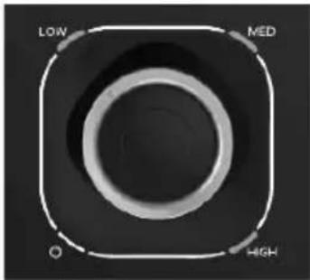
The water heater thermostat has been set at a temperature equal to or below 131^ F ( 55^ C). See Figure 1. If the water heater is going to have a set temperature above 120^ F, it is recommended to use an ASSE 1017 rated mixing valve to avoid severe burns or death from scalding temperatures.
natural_image
Top-down view of a camera lens with concentric rings and labeled sections (Low, High, MED), no additional text or symbols visible.Figure 1 - Thermostat
NOTE: After adjusting the water temperature at the thermostat, use a thermometer to measure the water temperature at a hot water outlet in the structure. The recommended temperature setting is 118^ F.
| Approximate Time / Temperature Relationships in Scalds | |
| 120°F More than 5 minutes | |
| 125°F 1 1/2 to 2 minutes | |
| 130°F About 30 seconds | |
| 135°F About 10 seconds | |
| 140°F Less than 5 seconds | |
| 145°F Less than 3 seconds | |
| 150°F About 1 1/2 seconds | |
| 155°F About 1 second |
Table 1 - Approx. Time / Temperature Relationships in Scalds

WARNING
Households with small children, disabled, or elderly persons may require a 120^ F or lower temperature setting to prevent severe personal injury or death due to scalding.
Part 2 - Prepare the Water Heater
Remove all sides of the shipping crate to allow the heater to be moved into its installation location.
NOTICE
UNCRATING THE WATER HEATER - Any claims for damage or shortage in shipment must be filed immediately against the transportation company by the consignee.
CAUTION
COLD WEATHER HANDLING - If the water heater has been stored in a very cold location (BELOW 0°F) before installation, handle with care until the components come to room temperature. Failure to do so could result in damage to the water heater.
A. Model Overview
The following figures detail specific water heater model components. Some components may ship factory installed. This depends on water heater model.
B. Locating the Water Heater

WARNING
This water heater is certified for indoor use only. DO NOT INSTALL OUTDOORS. Outdoor installations ARE NOT covered by warranty. Failure to install the water heater indoors could result in property damage, severe personal injury, or death.
CAUTION
All water heaters eventually leak. Locate the water heater where any leakage from the relief valve, related piping, tank, or connections will not result in damage to surrounding areas or lower floors of the building. Any water heater should be installed in such a manner that if it should leak the resulting flow of water will not cause damage to the area in which it is installed. National Plumbing codes require a drain pan for any water heater installation. Failure to install one is the sole responsibility of owner and/or installer. Reference UPC 2000 (Uniform Plumbing Code) Section 510 - Protection from Damage or IPC 200 (International Plumbing code) Section 504 - Safety Devices. Leakage damages ARE NOT covered by warranty. In addition, water leak detection devices and automatic water shutoff valves are readily available at plumbing supply houses. IT IS HIGHLY RECOMMENDED BY THE MANUFACTURER TO INSTALL WATER LEAK DETECTION DEVICES AND AUTOMATIC SHUTOFF VALVES IN ANY WATER HEATER INSTALLATION WHERE A LEAKAGE OF WATER COULD RESULT IN PROPERTY DAMAGES.
-
Installation Area (Mechanical Room) Operating Conditions
-
Ensure ambient temperatures are higher than 32^ / 0^ and lower than 104^ / 40^
- Avoid continuously high levels of humidity
- Never close existing ventilation openings
NOTE: When installing in a zero clearance location, it may not be possible to read or view some product labeling. It is recommended to make note of the water heater model and serial number.
NOTE: A combustible door or removable panel is acceptable front clearance.
NOTE: Keep water heater and hot outlet piping securely out of the reach of children to prevent tampering with the controls or contact with an extremely hot pipe.
CAUTION
The service life of the water heater's exposed metallic surfaces, such as the junction box, is directly influenced by proximity to damp and salty marine environments. In such areas higher concentration levels of chlorides from sea spray coupled with relative humidity can lead to degradation of water heater components and cause premature water heater failure. Such failures ARE NOT covered by warranty.
Failure of the water heater or components due to incorrect operating conditions IS NOT covered by product warranty.

WARNING
Incorrect ambient conditions can lead to damage to the heating system and put safe operation at risk. Ensure that the installation location adheres to the information included in this manual. Failure to do so could result in property damage, serious personal injury, or death.
- Choose a location for the water heater as centralized to the piping and electrical system as possible. Also, locate the water heater and domestic water piping where it will not be exposed to freezing temperatures. All piping should be insulated. Additionally, place the water heater so that the drain, controls, and inlets/outlets are easily accessible.
NOTE: To save on heating costs and improve energy efficiency keep the distance between the water heater and fixtures to a minimum to reduce heat loss from excess piping and keep friction loss at a minimum. Ensure all water heater piping is properly insulated to minimize heat loss.
NOTE: If you do not provide the minimum recommended service clearances it might not be possible to service the water heater without removing it from the space.
NOTE: In the State of California, the water heater must be braced, anchored, or strapped to avoid moving during an earthquake. Contact local utilities for code requirements in your area. Visit http://www.dsa.dgs.ca.gov or call 1-916-445-8100 and request instructions.
- Check area around water heater. Remove any combustible materials, gasoline, and other flammable liquids.

DANGER
This water heater must not be located near flammable liquids such as gasoline, butane, liquefied propane, adhesives, solvents, paint thinners, etc., as the controls of this water heater could ignite these vapors and cause an explosion resulting in property damage, severe personal injury, or death.

WARNING
This water heater must be installed upright in the vertical position as described in this manual. DO NOT attempt to install this water heater in any other orientation. Doing so will result in improper water heater operation and property damage, and could result in serious personal injury or death.
-
If the water heater is to replace an existing water heater, check for and correct any existing system problems such as:
-
System leaks
-
Location that could cause the system and water heater to freeze and leak
-
This water heater must be installed vertical on a level surface.
C. Water Chemistry Requirements
CAUTION
Chemical imbalance of the water supply may affect efficiency and cause severe damage to the appliance and associated equipment. Water quality must be professionally analyzed to determine whether it is necessary to treat the water. Various solutions are available to adjust water quality. Adverse water quality will affect the reliability of the system. In addition, operating temperatures above 135^ F will accelerate the build-up of lime scale and possibly shorten appliance service life. Failure of an appliance due to lime scale build-up, low pH, or other chemical imbalance IS NOT covered by the warranty.
The water must be potable, free of corrosive chemicals, sand, dirt, and other contaminates, and meet the manufacturer's requirements. It is up to the installer to ensure the water does not contain corrosive chemicals or elements that can damage the heat exchanger. Potable water is defined as drinkable water supplied from utility or well water in compliance with EPA secondary maximum contaminant levels (40 CFR Part 143.3). If the water contains contaminants higher than outlined by the EPA and the manufacturer, water treatment is recommended and additional, more frequent maintenance may be required. If you suspect that your water is contaminated in any way, discontinue use of the appliance and contact an authorized technician or licensed professional.
| Water Chemistry Requirements | |||
| pH | 6.5 - 8.5 | Chloride | Less than 250 mg/L |
| Total Dissolved Solids (TDS) | Less than 500 mg/L | Copper | Less than 1.0 mg/L |
| Free CO2 Iron | Less than 0.3 mg/L | ||
| Total Hardness | Less than 200 mg/L | Manganese | Less than 0.05 mg/L |
| Aluminum | Less than 0.2 mg/L | Zinc | Less than 5 mg/L |
Table 2 - Water Chemistry Requirements
*NOTE: To promote appliance service life, it is strongly recommended to follow the maintenance procedures in this manual.
CAUTION
Failure of electric elements due to lime scale build-up on the heating surface, low pH, or other imbalance IS NOT covered by the warranty.
D. Technical Specifications and Dimensions
| *Wattage (kW) | Voltage | Amperage | Phase | Circuit Breaker Size | Required Wire Size | |
| 3 | 110/120 | 28/29 | 1 | 1 x 30 | 10 AWG | |
| 6.5 | 240 | 27 | 1 x 30 | |||
| 8.5 | 36 | 1 x 40 | 6 AWG | |||
| 10.5 | 44 | 1 x 50 | ||||
| 13 | 54 | 1 x 60 | 4 AWG | |||
| Technical Data All Models | ||||||
| Minimum Water Flow to Activate Unit | 0.55 gpm | |||||
| Working Pressure 7 - 115 psi | (0.5 - 8 bar) | |||||
| Tested Pressure 230 psi (16 bar) | ||||||
| Water Connections 1/2" NPT | ||||||
| Elements 1 | ||||||
| Dimensions 12" (304 mm) | Width x 7" (178 mm) Height x 3.85" (98 mm) Depth | |||||
| Weight (Empty) 3.4 lb (1.54 kg) | ||||||
| Temperature Range 90 - 131 | °F (30 - 55°C) | |||||
| *Wattage (kW) | 110V | 120V | 208V | 240V |
| 3 | 3.1kW | 3.5kW - | ||
| 6.5 | - | - | 4.9kW | 6.5kW |
| 8.5 | 6.4kW | 8.5kW | ||
| 10.5 | 7.9kW | 10.5kW | ||
| 13 | 9.8kW | 13.0kW |
| Temperature Rise Δt (°F) | Flow Rate (GPM) | ||||
| 3kw | 6.5kw | 8.5kW | 10.5kW | 13kW | |
| 35 | 0.59 | 1.26 | 1.65 | 2.04 | 2.53 |
| 45 | 0.45 | 0.98 | 1.28 | 1.59 | 1.97 |
| 77 | 0.26 | 0.57 | 0.75 | 0.93 | 1.15 |
Table 3 - Technical Specifications - *Wattage based on maximum voltage.
Part 3 - Installation Instructions
Connect the included Pressure Relief Device (PRD) to the unit (Figure 2).
NOTE: IMPORTANT - Do not skip this step. A PRD must be installed with this water heater.
A. Wall Mounting the Water Heater
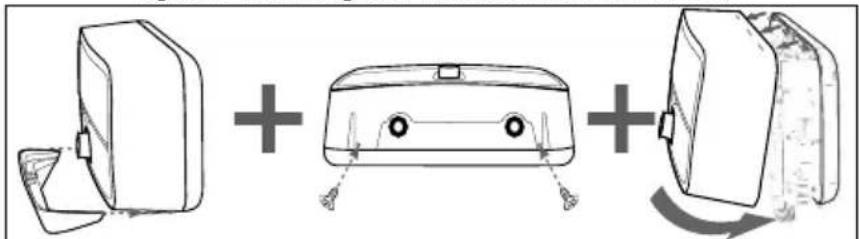
- Slide away the bottom cover and remove the knob by hand. Remove the two (2) screws attaching the water heater front cover. Remove the front cover. (Figure 3.)
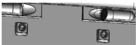
• Pass wires through knockout hole in back of unit (Right/Left back). See Figures 4 and 5.
• The mounting surface must be solid and secure. Do not install the unit above electrical boxes or junctions. - Position the unit on the mounting surface. Ensure the unit is level. Mount the unit to the wall with four (4) screws of at least one (1) inch in length at the marked points. See Figure 5.
NOTICE
Use screws suitable for the wall material and the weight of the water heater. Failure to do so could result in property damages and damage to the water heater. Such damages ARE NOT covered by product warranty.
• The appliance must be mounted horizontally, with water inlets and outlets at the bottom. See Figures 7 - 8.
! WARNING
This water heater must be installed upright in the vertical position as described in this manual. DO NOT attempt to install this water heater in any other orientation. Doing so will result in improper water heater operation and property damage, and could result in serious personal injury or death.
- Pull gently on the water heater to ensure that it is properly mounted.
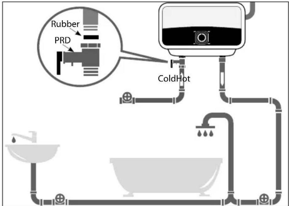
Figure 2 - Installing the Pressure Relief Device (PRD)
natural_image
Diagram showing three mechanical components with plus and minus signs, no text or symbols presentFigure 3 - Removing the Water Heater Cover
natural_image
Top-down view of two bullet-shaped objects with circular flanges, no text or symbols visibleFigure 4 - Wire Knockouts in Back of Unit
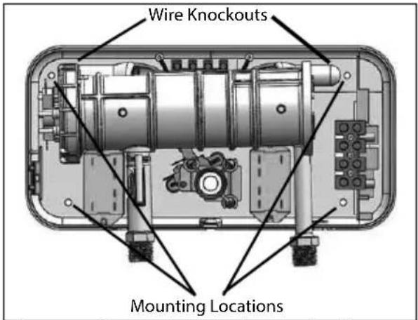
Figure 5 - Wire Knockouts and Mounting the Water Heater
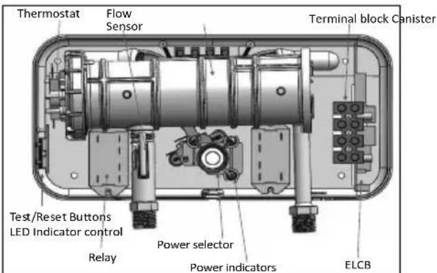
Figure 6 - Water Heater Component Detail
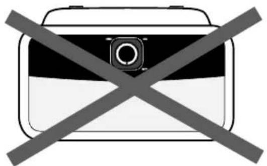
Figure 7 - DO NOT INSTALL THE WATER HEATER UPSIDE DOWN
NOTES:
- Minimum pipe size should match connection size. Upsize pipe accordingly if greater flow is required.
- Drains and check valve between will assist in purging air from system.
- These drawings are meant to demonstrate system piping only. The installer is responsible for all equipment and detailing required by local codes. In Massachusetts, you must install a vacuum relief valve per 248 CMR.
- A temperature and pressure (T&P) relief valve is not required for most installations, but may be required to meet local, state, or provincial codes. If codes require a T&P valve, install according to code and manufacturer instructions.
- Mixing valve application is optional, but recommended to help prevent scalding.
- It is highly recommended by the manufacturer to install water leak detection devices and automatic shutoff valves in any water heater installation where a leakage of water could result in property damages.
B. Plumbing
It is mandatory that all plumbing be done in accordance with federal, local, and state plumbing codes and practices. Failure to properly install the water heater WILL VOID the warranty. It is also necessary to use both thread tape and pipe dope on all mechanical plumbing connections.
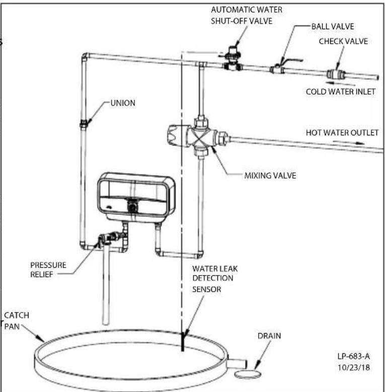
Figure 8 - Installation Detail
Install unions on the hot and cold water connections to easily disconnect the water heater for servicing.
- Connect the water inlet line to the entry point of the heater (left side inlet), and connect the outlet line to the water outlet. Use a line that can withstand a minimum pressure of 58 psi. Using any other type of line will cause damage. See Figure 8.
- Residential plumbing systems with unstable pressure or pressure above 73 psi require the application of a pressure stabilizer valve, set to 58 - 73 psi.
- Do not install the appliance with water inlets and outlets at the top. See Figure 7.
CAUTION
Do not apply heat to the Hot or Cold water heater connections. If sweat connections are used, sweat tubing to the adapter before fitting adapter to the water connections on the heater. Any heat applied to the water heater connections will permanently damage the water heater. Damages due to improper installation practices ARE NOT covered by warranty.
Failure of the water heater due to lime scale build-up on the heating surface, low pH, or other imbalance IS NOT covered by the warranty.
C. Pressure Relief Device (PRD)
For protection against excessive pressures in this water heater, install the supplied pressure relief device (PRD). The supplied PRD is marked with a maximum set pressure (123 psi). Install the PRD on the cold inlet line adapter of the water heater, and orient it or provide tubing so that any discharge from the valve will exit at least 6" above the structural floor. The relief line cannot be in contact with any live electrical parts. The discharge opening must not be blocked or reduced in size under any circumstances.
National Plumbing codes require a drain pan for any water heater installation. Failure to install one is the sole responsibility of owner and/or installer. Reference UPC 2000 (Uniform Plumbing Code) Section 510 - Protection from Damage or IPC 200 (International Plumbing code) Section 504 - Safety Devices.
D. Scalding
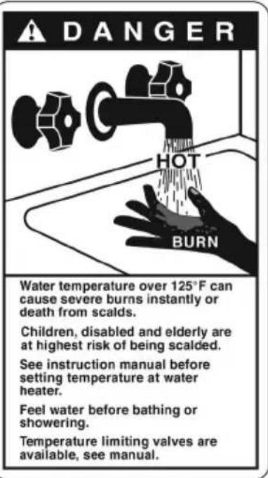
This water heater can deliver scalding water. Be careful whenever using hot water to avoid scalding injury. Certain appliances such as dishwashers and automatic clothes washers may require increased water temperatures. By setting the thermostat on this heater to obtain the increased water temperature required by these appliances you may create the potential for scald injury.
To protect against injury, install a mixing valve in the water system. This valve will reduce point of use discharge temperatures by mixing cold and hot water in branch supply lines. Such valves are available from your local plumbing supplier.
Table 1 details the relationship of water temperature and time with regard to scald injury and may be used as a guide in determining the safest water temperature for your applications.
WARNING
An ASSE 1017 or ASSE 1070 temperature limiting or mixing valve is recommended in installations servicing disabled or elderly persons, or children. Mixing valves do not eliminate the risk of scalding.
To avoid scalding:
- Set the water heater set point temperature as low as possible.
• Feel water before bathing or showering. - If thermostatic valves are required, use devices specifically designed for such purpose. Install these devices in accordance with instructions provided by the manufacturer.
Failure to install a temperature limiting or mixing valve and follow these instructions could result in property damage, severe personal injury, or death due to scalds.
E. Filling the Heater
- Make certain any drain valves in the system are completely closed.
- Open the shut-off valve in the cold water supply line.
- Open the hot water faucets to allow air to vent from the heater and piping.
- Allow sufficient time for the heater to completely fill with water.
- Check for and repair any leaks.
CAUTION
When fi lling the water heater, open a hot water tap to release air in the tank and piping. The tank must be full of water before the heater is turned on. Failure to ensure the water heater is full before turning it on could result in damage to the water heater and other property damages. Such damages ARE NOT covered by water heater warranty.
natural_image
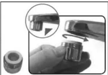
Close-up of a hand holding a small mechanical component with a magnified inset showing a close-up view (no text or symbols visible)Figure 9 - Aerator Installation (3kW Models ONLY)
F. Aerator Installation (3kW Models ONLY)
For optimal heating performance and proper operation, the provided 0.5 GPM aerator must be installed to your sink faucet. This will ensure a continuous flow and consistent maximum temperature rise. Output temperature will vary depending on seasonality and inlet cold water temperatures.
Maximum of 0.5 GPM flow rate is required for optimal heating performance.
Part 4 - Electrical Connection
CAUTION
Tank must be full of water before the power is turned on. The heating element will be damaged if energized for even a short time while tank is dry. Failures due to "dry-firing" ARE NOT covered by warranty.
The voltage requirement and dedicated wattage load for the heater is specified on the water heater rating label. Consult your local power company to determine if your electrical service is adequate for the additional load of the heater.
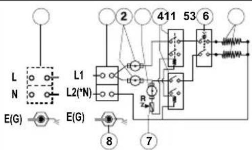
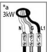
This water heater must be hard wired to the correct breaker size with the appropriate wire gauge. All wiring must conform to local code and the National Electric Code, and should be done by a qualified licensed electrician or the local electric utility. See Figures 4, 5, 10, and 11.
- Make sure power to the unit is shut off by means of the dedicated circuit breakers on the main electrical panel.
- Connect the appropriate AWG wire power cable for the model water heater to the terminal block and secure with conduit strain relief (not supplied).
- Make secure, appropriate wiring connections to the water heater per the National Electric Code.
• The unit must be grounded. - Secure the water heater cover once wiring connections have been made.
! WARNING
Be sure to ground the water heater. Failure to do so could result in property damage, severe personal injury, or death.
When the water heater is not within sight of the electrical circuit breakers, a circuit breaker lockout or additional local means of disconnection for all non-grounded conductors must be provided that is within sight of the appliance (Ref. NEC 422.31).
NOTE: It is recommended that the water heater electrical connections be tested once a year by a qualified technician.
After wiring is complete, slide the gray bottom cover of the water heater into place by hand. Use the two (2) screws removed earlier in the installation process to secure the front cover of the water heater.
- 3-3.4kW (110V) - Install Line 1 (L1), E(G)-Ground, N (Neutral)
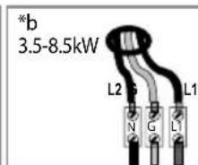
- 3.5-8.5kW (240V) - Install Line 1 (L1), E(G)-Ground, Line 2 (L2)
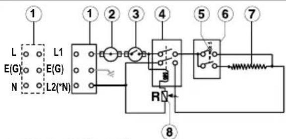
- Terminal block
- Thermal cut-out with reset
- Thermal cut-out
- Relay
- Light
- Switch 0-Off
(Option) 1- Low
- Heating element
- Read sensor
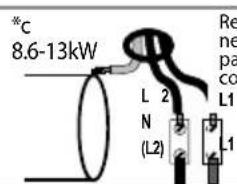
8.6kW-10.5kW (240V)
- Terminal block
- Thermal cut-out with reset
- Thermal Cut out
- Relay
- Switch 0-Off
1- Low
2- Medium
3- High
- Heating element
- Read sensor
- EARTH(G) Connection in the heating canister
10.6kW-13kW (240V)
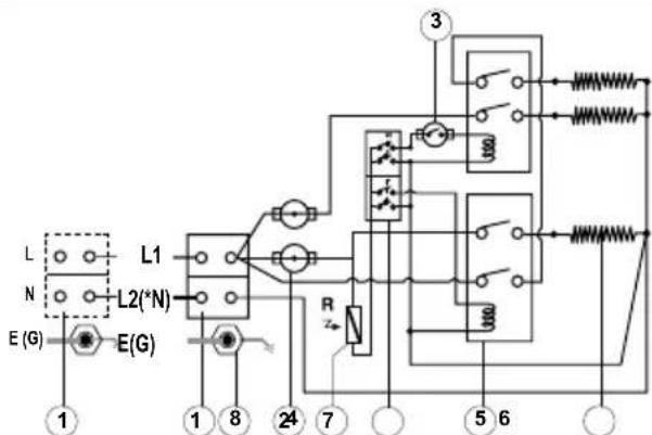
- Terminal block
- Thermostat with reset
- Thermostat
- Switches with lights
- Relay
- Heating elements
- Read sensor
- EARTH(G) Connection in the heating canister
L1/L2 = Line1/Line2 (Black or Red) E(G) = Ground (Green/Yellow)
*N = Neutral (White or Silver)
*Neutral acts as Line 2 (L2) for 220V/240V
*Neutral does not have to be connected for 3.5kW-13kW
Figure 10 - Water Heater Wiring
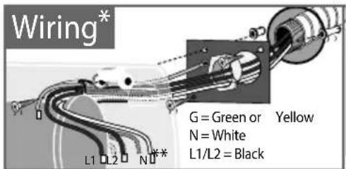
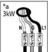
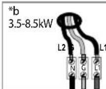
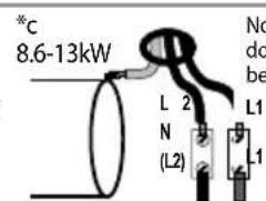
Figure 11 - Water Heater Wiring Detail
Part 5 - Installation Checklist
| Water Heater Location Yes No | ||
| Close to area of heated water demand | ||
| Indoors and protected from freezing temperatures | ||
| Area free of fl ammable vapors | ||
| Provisions made to protect area from water damage | ||
| Suffi cient room to service heater | ||
| Relief Valve YesNo | ||
| Pressure Relief Device (PRD) properly installed and discharge line run to open drain | ||
| Discharge line protected from freezing | ||
| Wiring YesNo | ||
| Power supply voltage agrees with water heater rating plate | ||
| Branch circuit wire and fusing or circuit breaker of proper size | ||
| Electrical connections tight and unit properly grounded | ||
| Water Supply YesNo | ||
| Water heater completely fi lled with water BEFORE operating the unit | ||
| Air purged from water heater and piping | ||
| Water connections tight and free of leaks |
Table 4 - Installation Checklist
Part 6 - Operation
| CAUTION |
| The water heater must be full of water before the power is turned on. The heater will be damaged if energized for even a short time while dry. Failures due to "dry-fi ring" ARE NOT covered by warranty. |
A. Starting and Testing
• Supply power to the water heater by turning on the circuit breaker.
- Turn the control knob in a clockwise direction.
- The LED on the control knob will turn on until the water temperature has reached the thermostat temperature setting. The light will come back on any time the water temperature inside the tank drops below the thermostat setting.
B. Thermostat Adjustment
The temperature of the hot water is adjusted by rotating the knob located on the front cover.
- Turn the knob clockwise to increase temperature.
- Turn the knob counterclockwise to decrease temperature.
• After adjusting the water temperature, allow the water heater enough time to heat the water to temperature. After the water heater has stopped heating, measure the water temperature at the nearest hot water outlet in the structure.
• Temperature can range from 90 - 134.6 °F (30 - 57°C).
| *Wattage (kW) | Low kW | Medium kW | High kW |
| 3 | 1 | 2 | 3.1 |
| 6.5 | 3 | 3.5 | 6.5 |
| 8.5 | 3.8 | 4.7 | 8.5 |
| 10.5 | 5.25 | 5.25 | 10.5 |
| 13 | 4.5 | 8.5 | 13 |
Table 5 - Model Operation Guide (by kW)
Part 7 - Maintenance
| WARNING |
| Do not attempt to repair this water heater yourself. Call a qualified service technician for assistance. Always turn off the power supply to the heater prior to servicing or draining the heater. Failure to do so could result in property damage, severe personal injury, or death. |
| NOTICE |
| For most of these maintenance operations, the water will have to be drained from the heater. For all of these operations, the power should be turned off at the circuit breaker and the front cover removed. |
A. Removing the Cover
- Pry off the round knob with a small fl at head screwdriver.
- Slide away the bottom cover by hand. (Figure 3.)
- Remove the two (2) screws attaching the water heater front cover. Remove the front cover.
- When reassembling, work in the opposite way.
B. Draining the Heater
If the heater has been installed with a drain valve, turn the water heater inlet off. Open a faucet or outlet in the system. Then open the drain valve to drain the heater.
C. Removing the Heating Element
- Shut off the power supply and drain the water heater.
- Remove the front cover following the instructions above. Disconnect the wires from the element. See Figure 13.
- Use a pipe wrench to remove the element containing cap from the water heating assembly.
- Carefully remove the heating element.
D. Descaling the Heating Element
Scale deposits can affect the heating capability of the element. Heavy scale can even cause damage to the element. The element can be descaled either chemically or manually.
- Soak the element in white vinegar or other food grade descaling solution approved for use in potable water systems.
- Once descaled, rinse well with a fresh water / baking soda solution.
The element can also be descaled manually:
- After the element has dried, use a soft brush (non-metallic to prevent damaging the element sheath) on the element.
- Brush the dried minerals off.
Reinstall the element after descaling. Ensure the element gasket is installed and that the element is rewired correctly.
CAUTION
Ensure the tank has been refilled with water before restoring power to the water heater. Failures due to "dry-fi ring" ARE NOT covered by warranty.
Part 8 - Troubleshooting
| Problem Possible | Cause Solution | |
| Water Not Hot Enough | Too much water flowing through the heater | Reduce the flow rate at the faucet or slightly close the shutoff valve on the unit's incoming water supply line to reduce flow rate |
| Reduction in the ambient temperature or temperature setting is too low | Increase the temperature setting on the unit | |
| Water pressure less than 7 psi (0.5 bar) | Make sure the shutoff valve is fully open and the water supply line is not blocked | |
| Electrical malfunction | Contact a qualified electrician or your local authorized distributor for service | |
| Water Too Hot | Not enough water flowing through the heater | Increase the flow rate at the water outlet |
| Increase in the ambient temperature or temperature setting is too high | Switch to a lower temperature setting | |
| Heater Shuts Off During Use | Power outage or faulty wiring | Check the power supply and circuit breaker. If problem persists, contact a qualified electrician. |
| Water Stops Flowing | Blockage in water pipes or hoses | Ensure the main water shutoff valve is fully open and there are no obstructions in the water supply line |
| No water supply | ||
| Problem Possible Cause Solution | ||
| Water Temperature Varies from Hot to Cold During Use | Water pressure has dropped below minimum level | Increase the flow rate from the water supply source |
| No Hot Water with the Unit's Water Supply Line Shutoff Valve Fully Open | Power outage or faulty wiring Check the power supply and circuit breaker. | |
| The flow rate needed to activate the heating element (0.5 gpm) has not been reached. | Increase the flow rate from the water supply source.Clean the filter screen on the unit's water inlet by turning the circuit breaker off, opening the valve to release pressure from the unit, and turning the circuit breaker on. | |
| High Limit Has Been Tripped | Check that the high limit reset buttons are pushed in. Follow steps to reset the switch, this manual. | |
| Leaks | Check for leaks at fittings | Check water fittings. Remove front cover and inspect heating element gasket. |
| If tank is leaking | Turn off water supply at the shutoff valve. Shut off power to the water heater, and review warranty to see if heater is still within warranty period. | |
Table 6 - Troubleshooting

WARNING
The risk of scald injury increases as you increase water temperature. A lower setting is more economical and reduces the risk of scalding. Use a water tempering or mixing valve and extreme caution when using hot water to avoid scald injury. Consult codes for conformance. Failure to follow the instructions in this warning statement could result in serious personal injury or death from scalds.
Be sure to disconnect electrical power before performing service. Failure to do so could result in electrical shock, property damage, serious personal injury, or death.
CAUTION
If draining of the water heater is necessary, open the relief valve or a hot water tap to prevent vacuum buildup in the tank and piping.
A. Resetting the High Limit Switches
Occasionally, the high temperature limit shut off device may trip the resets. This occurs when water temperature exceeds 185^ F / 85^ C. The shut-off devices may also trigger due to a power outage or electrical storm.
To reach the high limit switches:
- Shut off the circuit breaker and remove the front cover.
- Locate the resets to the right of the heating unit canister. See Figure 12.
- Firmly press the reset switches with the tip of a ball point pen or similar object.
CAUTION
Call a technician if the high limits need to be reset frequently.
B. Checking Thermostat Operation
To check thermostat operation:
- Turn the temperature dial from off to low. Open a hot water
outlet to create a demand on the hot water heater. Check water
temperature at the outlet with a thermometer. If water is too hot or water does not get hot, turn off the power supply and call a qualified service technician.
- If the water is heating properly, turn the dial to the desired setting. NOTE: A lower setting is more economical and reduces the risk of scalding.
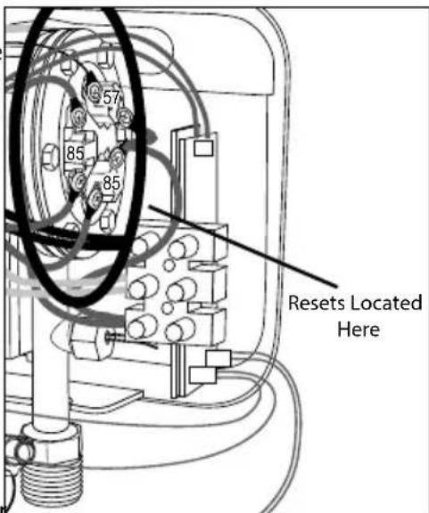
Figure 12 - Reset Locations
NOTE: After adjusting the water temperature, allow the heater enough time to heat the water to temperature.
Then use a thermometer to measure the water temperature at a hot water outlet in the structure.
C. Changing the Heating Element
- Turn off the power supply and drain the water heater (see procedure, this manual).
- Remove heating element (see procedure, this manual).
• Install new element with gasket, making sure the gasket and element are positioned correctly. Use a pipe wrench to tighten the element containing cap. - Reconnect the wires to the element. Reinstall the front cover (see procedure, this manual).
- Refi II the water heater with water before restoring power.
D. Changing the Thermostat
• Turn off the power supply.
- Disconnect the wire connectors from the thermostats. Take care to note / label removed wires to aid in reinstallation.
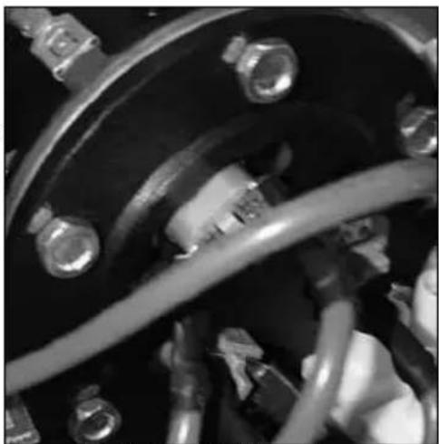
- Use an 8mm wrench or socket driver to remove the six (6) nuts and bolts from the canister. See Figure 13. Take care not to lose these bolts and nuts. Replacements are not included with the replacement thermostat.
- Remove the plastic cover.
• Install the new thermostat(s).
- Reinstall the plastic cover.
- Use an 8mm wrench or socket driver to reinstall the six (6) nuts and bolts to the canister.
- Reconnect the wiring.
- Restore power to the water heater and observe operation.
natural_image
Close-up of mechanical components with hoses and bolts, no visible text or symbolsFigure 14 - Nut and Bolt Locations
Part 9 - Replacement Parts
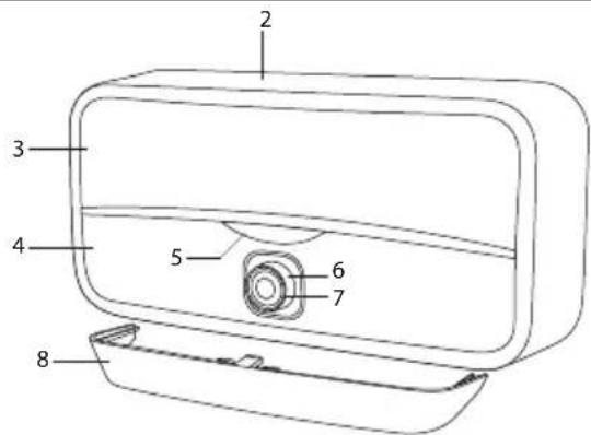
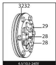
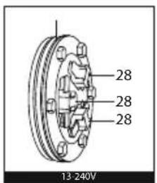
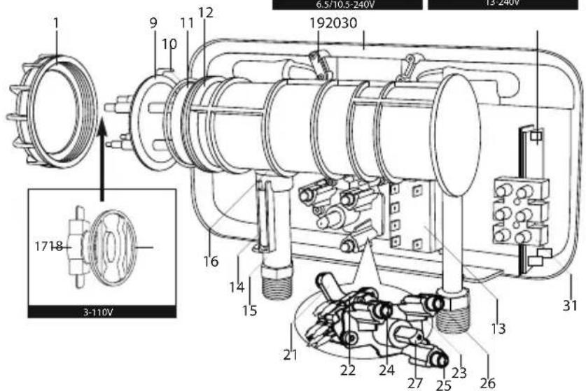
Figure 13 - Replacement Parts
| Item # | Description | Part # | ||||
| Model | ||||||
| 3kW 6.5 | kW 8.5kW 10.5 | 5kW 13kW | ||||
| 1 Big | Plastic Nut 65118337 | |||||
| 2 Front Cover 65118338 | ||||||
| 3 Top | Panel 65118339 | |||||
| 4 Low | Panel 65118340 | |||||
| 5 Logo | 65118341 | |||||
| 6 | Knob (Regulation) | 65118342 | ||||
| 7 | Knob Ring | 65118343 | ||||
| 8 | Bottom Cover | 65118344 | ||||
| 9 | Heating Element | 65118418 | 65118419 | 65118421 | 65118422 | |
| 10 | O Ring for Deep Flange | 65180269 | ||||
| 11 | Sleeve SS 65180307 | |||||
| 12 Heating Tank 65162074 | 65 | 18345 | ||||
| 13 | Relay | 65118346 | ||||
| 14 | Sensor (Reed) | 65180318 | ||||
| 15 | Inlet Pipe 65118347 | |||||
| 16 | O Ring 14x2.62 | 65180221 | ||||
| 17 | Thermostat ELTH with Reset | 65180209 | ||||
| 18 | Thermostat Holder | 65118286 | ||||
| 19 Cable Holder | 65118294 | |||||
| 20 | Back Cover | 65118348 | ||||
| 21 | Power Selector Housing | 65118293 | ||||
| 22 | Microswitch 3 Contacts | 65180239 | ||||
| 23 | LED Holder | 65118349 | ||||
| 24 | LED (Blue+Brown Wire) | 65118350 | ||||
| 25 | LED (Yellow+Black Wire) | 65118351 | ||||
| 26 | LED (Black+Red Wire) | 65118352 | ||||
| 27 | Knob Spindle | 65118295 | ||||
| 28 | Thermostat 85C | 65118353 | ||||
| 29 | Thermostat T1 | 65180328 | ||||
| 30 LED PCB | 65118354 | |||||
| 31 | Terminal Block | 65153714 | ||||
| 32 | Gasket 3mm | 65118420 | ||||
Table 7 - Replacement Part Numbers
Everlast Single and Multipoint Electric Tankless Water Heater Limited Warranty
The manufacturer warrants each small capacity point of use, electric water heater and its components to be free from defects in materials and workmanship according to the following terms, conditions, and time periods. UNLESS OTHERWISE NOTED THESE WARRANTIES COMMENCE ON THE DATE OF INSTALLATION. This limited warranty is only available to the original consumer purchaser (hereinafter "Owner") of the water heater, and is non-transferable.
WARRANTY PERIODS
| Slim Multi Electric Water Heater | Parts Tank | |
| Two (2) Years Six (6) Years | ||
COVERAGE
A. During the first two (2) years after the original date of installation the manufacturer warrants that it will repair or replace, at its option, any defective or malfunctioning component of the water heater. Replacement components will be warranted for ninety (90) days.
B. Should a defect or malfunction result in a leakage of water from the water heater within the first six (6) years after the original date of installation due to defective material or workmanship, malfunction, or failure to comply with the above warranty, with such defect or malfunction having been verified by an authorized representative of the manufacturer, the manufacturer will repair or replace, at its option, the defective or malfunctioning water heater. Replacements will be of the nearest comparable model available at the time of replacement. The replacement water heater will be warranted for the unexpired portion of the applicable warranty period of the original water heater.
C. In the event of a leakage of water of a replacement water heater due to defective material or workmanship, malfunction, or failure to comply with the above warranty, the manufacturer reserves the right to refund to the Owner the published wholesale price available at the date of manufacture of the original water heater.
D. If government regulations, industry certification, or similar standards require the replacement water heater or component(s) to have features not found in the defective water heater or component(s), the Owner will be charged the difference in price represented by those required features. If the Owner pays the price difference for those required features and/or to upgrade the size and/or other features available on a new replacement water heater or component(s), the Owner will also receive a complete new limited warranty for that replacement water heater or component(s).
E. If at the time of a request for service the Owner cannot provide a copy of the original sales receipt or the warranty registration, the warranty period for the water heater shall then be deemed to have commenced on the date of manufacture of the water heater and NOT the date of installation of the water heater, and be covered by the unexpired portion of the warranty detailed above.
F. This warranty extends only to water heaters utilized in water heating applications that have been properly installed by qualified professionals based upon the manufacturer installation instructions.
G. It is expressly agreed between the manufacturer and the Owner that repair, replacement, or refund are the exclusive remedies of the Owner.
OWNER RESPONSIBILITIES
The Owner or Qualified Installer / Service Technician must:
-
Have a relief valve bearing the listing marks of the American Society of Mechanical Engineers (ASME) installed with the water heater assembly in accordance with federal, state, and local codes.
-
Have a vacuum relief valve certified to ANSI Z21.22 - Relief Valves for Hot Water Supply Systems - installed with the water heater assembly in accordance with federal, state, and local codes and in installations prone to vacuum related damages.
-
Maintain the water heater in accordance with the maintenance procedure listed in the manufacturer's provided instructions. Preventive maintenance can help avoid any unnecessary breakdown of the water heater and keep it running at optimum efficiency.
-
Maintain all related system components in good operating condition.
-
Use the water heater at water pressures not exceeding the working pressure shown on the rating plate.
f6. Keep the water heater free of damaging scale deposits.
- Make provisions so if the water heater or any component or connection thereto should leak, the resulting flow of water will not cause damage to the area in which it is installed.
WARRANTY EXCLUSIONS
This limited warranty will not cover:
- Any water heater purchased from an unauthorized dealer.
-
Any water heater not installed by a qualified heating installer / service technician, or installations that do not conform to ANSI, CSA, and/or UL standards, as well as any applicable national or local building codes.
-
Service trips to teach the Owner how to install, use, maintain, or to bring the water heater installation into compliance with local building codes and regulations.
-
The workmanship of any installer. The manufacturer disclaims and does not assume any liability of any nature caused by improper installation, repair, or maintenance.
-
Electricity or fuel costs, or increased or unrealized savings for same, for any reason whatsoever.
-
Any water damage arising, directly or indirectly, from any defect in the water heater or component part(s) or from its use.
-
Any incidental, consequential, special, or contingent damages or expenses arising, directly or indirectly, from any defect in the water heater or the use of the water heater.
-
Failure to locate the water heater in an area where leakage of the tank or water line connections and the relief valve will not result in damage to the area adjacent to the water heater or lower floors of the structure, as well as failure to install the water heater in or with a properly sized drain pan routed to an approved drainage location.
-
Any failed components of the system not manufactured by the manufacturer as part of the water heater.
-
Water heaters repaired or altered without the prior written approval of the manufacturer.
-
Damages, malfunctions, or failures resulting from improper installation, or failure to install the water heater in accordance with applicable building codes/ordinances or good plumbing and electrical trade practices; or failure to operate and maintain the water heater in accordance with the manufacturer's provided instructions.
-
Damages, malfunctions, or failures resulting from failure to operate the water heater at pressures not exceeding the working pressure shown on the rating label.
-
Failure to operate the water heater in an open system, or in a closed system with a properly sized and installed thermal expansion tank.
-
Failure or performance problems caused by improper sizing of the water heater, expansion device, piping, electric service voltage, wiring or fusing.
- Damages, malfunctions, or failures resulting from vacuum conditions.
- Damages, malfunctions, or failures caused by operating the water heater with modified, altered, or unapprove components, or any component / attachment not supplied by the manufacturer.
- Damages, malfunctions, or failures caused by abuse, accident, fire, flood, freeze, lightning, electrochemical reaction, acts of God and the like.
- Tank failures (leaks) caused by operating the water heater in a corrosive or contaminated atmosphere.
- Damages, malfunctions, or failures caused by operating the water heater with an empty or partially empty tank ("dry fi ring"), or failures caused by operating the water heater when it is not supplied with potable water, free to circulate at all times.
- Failure of the heater due to the accumulation of solid materials or lime deposits.
- Any damage or failure resulting from improper water chemistry, or heating anything other than potable water. WATER CHEMISTRY REQUIREMENTS - Water pH between 6.5 and 8.5. Hardness less than 7 grains (120 mg/L). Chloride concentration less than 100 ppm (mg/L). TDS less than 500 ppm (mg/L).
- Production of noise, taste, odors, discoloration, or rusty water.
- Water heaters replaced for cosmetic reasons.
- Components of the water heater that are not defective, but must be replaced during the warranty period as a result of reasonable wear and tear.
- Components of the water heater that are subject to warranties, if any, given by their manufacturers; the manufacturer does not adopt these warranties.
- Damages, malfunctions, or failures resulting from the use of any attachment(s) not supplied by the manufacturer.
- Water heaters installed outside the fi fty states (and the District of Columbia) of the United States of America and Canada.
- Water heaters moved from the original installation location.
- Water heaters that have had their rating labels removed.
PROCEDURES FOR WARRANTY SERVICE REQUESTS
Any claim for warranty assistance must be made promptly. Determine if the water heater is "in-warranty" (that is, within the applicable warranty period) by reviewing a copy of the original sales receipt or warranty registration. The Owner must present a copy of the original sales receipt or warranty registration for a warranty service request.
If the water heater is "in-warranty", contact the retailer from whom the water heater was purchased (or the installer) for assistance. Be prepared to provide the retailer or installer with a copy of the original receipt, complete model and serial numbers, and the date of installation of the water heater, in addition to explanation of the water heater problem.
Warranty coverage is subject to validation of "in-warranty" coverage by the manufacturer claims department personnel. All alleged defective or malfunctioning components must be returned to the manufacturer via the local distribution channels where original purchase was made. NOTE: Any components or heaters returned to the manufacturer for warranty analysis will become the property of the manufacturer and will not be returned, even if credit is denied. If all warranty conditions are satisfied, the manufacturer will provide replacement components to the retailer.
For questions about the coverage of this warranty, please contact the manufacturer at the following address or phone
number: HTP (an Ariston Thermo Group Company), 272 Duchaine Blvd, New Bedford, MA, 02745 Attention: Warranty Service Department, 1 (774) 271 3108.
SERVICE, LABOR, AND SHIPPING COSTS
Except when specifically prohibited by the applicable state law, the Owner, and not the Manufacturer, shall be liable for and shall pay for all charges for labor or other expenses incurred in the removal, repair, or replacement of the appliance or any component part(s) claimed to be defective or any expense incurred to remedy any defect in the product. Such charges include, but are not necessarily limited to:
- All freight, shipping, handling, and delivery costs of forwarding a new appliance or replacement part(s) to the owner.
- All costs necessary or incidental in removing the defective appliance or component part(s) and installing a new appliance or replacement part(s).
- All administrative fees incurred by the Owner, as well as material required to complete, and/or permits required for, installation of a new appliance or replacement part(s), and
- All costs necessary or incidental in returning the defective water heater or component part(s) to a location designated by the manufacturer.
LIMITATIONS OF YOUR WARRANTY AND REMEDIES THE FOREGOING WARRANTIES ARE EXCLUSIVE AND ARE GIVEN AND ACCEPTED TO THE FURTHEST EXTENT UNDER APPLICABLE LAW IN LIEU OF ANY AND ALL OTHER WARRANTIES, EXPRESS OR IMPLIED, INCLUDING WITHOUT LIMITATION THE IMPLIED WARRANTIES OF MERCHANTABILITY AND FITNESS FOR A PARTICULAR PURPOSE AND ANY OBLIGATION, LIABILITY, RIGHT, CLAIM OR REMEDY IN CONTRACT OR TORT, WHETHER OR NOT ARISING FROM THE MANUFACTURER'S NEGLIGENCE, ACTUAL OR IMPUTED. THE REMEDIES OF THE OWNER SHALL BE LIMITED TO THOSE PROVIDED HEREIN TO THE EXCLUSION OF ANY OTHER REMEDIES INCLUDING WITHOUT LIMITATION, INCIDENTAL OR CONSEQUENTIAL DAMAGES, SAID INCIDENTAL AND CONSEQUENTIAL DAMAGES INCLUDING, BUT NOT LIMITED TO, PROPERTY DAMAGE, LOST PROFIT OR DAMAGES ALLEGED TO HAVE BEEN CAUSED BY ANY FAILURE OF THE MANUFACTURER TO MEET ANY OBLIGATION UNDER THIS AGREEMENT INCLUDING THE OBLIGATION TO REPAIR AND REPLACE SET FORTH ABOVE. NO AGREEMENT VARYING OR EXTENDING THE FOREGOING WARRANTIES, REMEDIES OR THIS LIMITATION WILL BE BINDING UPON THE MANUFACTURER. UNLESS IN WRITING AND SIGNED BY A DULY AUTHORIZED OFFICER OF THE MANUFACTURER. THE WARRANTIES STATED HEREIN ARE NOT TRANSFERABLE AND SHALL BE FOR THE BENEFIT OF THE OWNER ONLY.
NO OTHER WARRANTIES
This warranty gives the Owner specific legal rights. The Owner may also have other rights that vary from state to state. Some states do not allow the exclusion or limitation of incidental or consequential damages so this limitation or exclusion may not apply to the Owner. These are the only written warranties applicable to the water heater manufactured and sold by the manufacturer. The manufacturer neither assumes nor authorizes anyone to assume for it any other obligation or liability in connection with said water heaters.
The manufacturer reserves the right to change specifications or discontinue models without notice.
| Customer Installation Record Form | |
| The following form should be completed by the qualified installer / service technician for you to keep as a record of the installation in case of a warranty claim. After reading the important notes at the bottom of the page, please also sign this document. | |
| Customer's Name | |
| Date of Installation | |
| Installation Address | |
| Product Model / Serial Number(s) | |
| Comments | |
| Installer's Code / Name | |
| Installers Phone Number | |
| Signed by Installer | |
| Signed by Customer | |
| Installation Notes | |
IMPORTANT
Customer: Please only sign after the qualified installer / service technician has fully reviewed the installation, safety, proper operation, and maintenance of the system. If the system has any problems please call the qualified installer / service technician. If you are unable to make contact, please call your sales representative.
Distributor / Dealer: Please insert contact details.
ENCADRÉS D'AVERTISSEMENTS SPÉCIAUX
| Part 1 - General Safety Information 3 | Part 6 - Operation | 12 |
| A. When Servicing the Water Heating System 4 | A. Starting and Testing | 12 |
| B. Heater Water 4 | B. Thermostat Adjustment | 12 |
| C. Freeze Protection 4 | Part 7 - Maintenance | 12 |
| D. Water Temperature Adjustment 4 | A. Removing the Cover | 13 |
| Part 2 - Prepare the Water Heater 5 | B. Draining the Heater | 13 |
| A. Model Overview 5 | C. Removing the Heating Element | 13 |
| B. Locating the Water Heater 5 | D. Descaling the Heating Element | 13 |
| C. Water Chemistry Requirements | 6 Part 8 - Troubleshooting | 13 |
| D. Technical Specifications and Dimensions | 7 A. Resetting the High Limit Switches | 14 |
| Part 3 - Installation Instructions | 7 B. Checking Thermostat Operation | 14 |
| A. Wall Mounting the Water Heater | 7 C. Changing the Heating Element | 15 |
| B. Plumbing | 9 D. Changing the Thermostat | 15 |
| C. Pressure Relief Device (PRD) | 9 Part 9 - Replacement Parts | 15 |
| D. Scalding | 9 Limited Warranty | 17 |
| E. Filling the Heater | 10 Customer Installation Record Form | 19 |
| F. Aerator Installation (3kW Models ONLY) | 10 | |
| Part 4 - Electrical Connection | 10 | |
| Part 5 - Installation Checklist | 12 |
AVERTISSEMENT
CONSIGNES DE SÉCURITÉ IMPORTANTES
natural_image
Circular mechanical component with concentric rings and labeled sections (LOW, MED, HIGH), no readable text or symbols beyond labels.Figure 15 - Thermostat
natural_image
Diagram showing three mechanical components with plus and minus signs, no text or symbols presentnatural_image
Top-down view of two identical rocket engine flares mounted on a flat surface, with no visible text or symbols.Figure 20 - N'INSTALLEZ PAS LE CHAUFFE-EAU À L'ENVERS
REMARQUES :
natural_image
Close-up of a hand holding a small mechanical component with a magnified inset showing the process (no text or symbols visible)*N = Neutre (Blanc ou Argent)
natural_image
Close-up of mechanical components with hoses and bolts, no visible text or symbolsEXCLUSIONS DE LA GARANTIE
Table of Contents
Part 1 - General Safety Information 3
| A. When Servicing the Water Heating System |
| B. Heater Water 4 |
| C. Freeze Protection 4 |
| D. Water Temperature Adjustment 4 |
Part 2 - Prepare the Water Heater 5
| A. Model Overview 5 |
| B. Locating the Water Heater 5 |
| C. Water Chemistry Requirements 6 |
| D. Technical Specifications and Dimensions 7 |
Part 3 - Installation Instructions 7
| A. Wall Mounting the Water Heater 7 |
| B. Plumbing |
| C. Pressure Relief Device (PRD) |
| D. Scalding |
| E. Filling the Heater |
| F. Aerator Installation (3kW Models ONLY) |
Part 4 - Electrical Connection 10
4 Part 5 - Installation Checklist 12
| Part 6 - Operation | 12 |
| A. Starting and Testing | 12 |
| B. Thermostat Adjustment | 12 |
Part 7 - Maintenance 12
| A. Removing the Cover | 13 |
| B. Draining the Heater | 13 |
| C. Removing the Heating Element | 13 |
| D. Descaling the Heating Element | 13 |
Part 8 - Troubleshooting 13
| A. Resetting the High Limit Switches | 14 |
| B. Checking Thermostat Operation | 14 |
| C. Changing the Heating Element 15 | |
| D. Changing the Thermostat | 15 |
| Part 9 - Replacement Parts | 15 |
| Limited Warranty | 17 |
| Customer Installation Record Form | 19 |
ADVERTENCIA
natural_image
Top-down view of a circular mechanical component with labeled sections: LOW, MED, and HIGH (no additional text or symbols)Figure 29 - Termostato
natural_image
Diagram showing three mechanical components with plus and minus signs, no text or symbols presentnatural_image
Top-down view of two cylindrical objects with circular flanges, placed on a surface with two smaller square units below (no text or symbols visible)Figure 34 - NO INSTALAR EL CALENTADOR DE AGUA AL REVÉS
NOTAS:
natural_image
Close-up of hands holding a small mechanical component with a magnified inset showing a hand turning a valve (no text or symbols visible)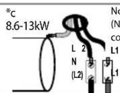
natural_image
Close-up of mechanical components with hoses and bolts, no visible text or symbolsnatural_image
Abstract black-and-white circular diagram with three curved arrows forming a cycle around a stylized cloud or tree silhouette (no text or symbols)WE MAKE USE OF RECYCLED PAPER

Ariston Thermo S.p.A.
Viale Aristide Merloni, 45
60044 Fabriano (AN)
Tel. (+39) 0732.6011
ariston.com
- Electric Tankless Water Heaters
- NOTICE
- AVERTISSEMENT
- DANGER
- WARNING
- CAUTION
- Foreword
- For the Installer
- Installations Must Comply With:
- IMPORTANT SAFETY INSTRUCTIONS
- SAVE THESE INSTRUCTIONS
- Part 1 - General Safety Information
- FAILURE TO ADHERE TO THE GUIDELINES ON THIS PAGE CAN RESULT IN SUBSTANTIAL PROPERTY DAMAGE, SEVERE PERSONAL INJURY, OR DEATH.
- When Servicing the Water Heating System
- Heater Water
- Freeze Protection
- Water Temperature Adjustment
- Part 2 - Prepare the Water Heater
- Model Overview
- Locating the Water Heater
- Water Chemistry Requirements
- Part 3 - Installation Instructions
- Wall Mounting the Water Heater
- ! WARNING
- NOTES:
- Plumbing
- Pressure Relief Device (PRD)
- Scalding
- Filling the Heater
- Aerator Installation (3kW Models ONLY)
- Part 4 - Electrical Connection
- Starting and Testing
- Thermostat Adjustment
- Removing the Cover
- Draining the Heater
- Removing the Heating Element
- Descaling the Heating Element
- Resetting the High Limit Switches
- Checking Thermostat Operation
- Changing the Heating Element
- Changing the Thermostat
- Part 9 - Replacement Parts
- Everlast Single and Multipoint Electric Tankless Water Heater Limited Warranty
- COVERAGE
- OWNER RESPONSIBILITIES
- WARRANTY EXCLUSIONS
- PROCEDURES FOR WARRANTY SERVICE REQUESTS
- SERVICE, LABOR, AND SHIPPING COSTS
- NO OTHER WARRANTIES
- ENCADRÉS D'AVERTISSEMENTS SPÉCIAUX
- CONSIGNES DE SÉCURITÉ IMPORTANTES
- REMARQUES :
- EXCLUSIONS DE LA GARANTIE
- ADVERTENCIA
- NOTAS:
Brand : Ariston Thermo
Model : Aures Slim
Category : Boiler