
GS1100-24E - Network switch ZYXEL - Free user manual and instructions
Find the device manual for free GS1100-24E ZYXEL in PDF.


| Product Type | Network Switch |
| Brand | ZyXEL |
| Model | GS1100-24E |
| Ports | 24 x RJ-45 10/100/1000 Mbps Gigabit Ethernet |
| Switch Type | Unmanaged |
| MAC Address Table | 8K entries |
| Switching Capacity | 48 Gbps |
| Forwarding Rate | 35.7 Mpps |
| Jumbo Frame Support | Up to 9K bytes |
| Dimensions (W x D x H) | 440 x 160 x 44 mm |
| Weight | 1.7 kg |
| Power Supply | Internal, 100-240V AC, 50/60 Hz |
| Power Consumption | 14.4W max |
| Cooling | Fanless (silent operation) |
| Operating Temperature | 0°C to 40°C |
| LED Indicators | Per port: Link/Activity; Device: Power |
| Mounting | Desktop or 19-inch rack-mountable (brackets included) |
| Standards | IEEE 802.3, 802.3u, 802.3ab, 802.3x |
| Features | Auto-negotiation, Auto-MDI/MDIX, Store-and-forward, Flow control |
| Maintenance | Clean with a soft, dry cloth; do not use liquids or chemicals |
| Safety | CE, FCC compliant |
| Spare Parts / Repairability | No user-serviceable parts; internal power supply; contact support for issues |
Frequently Asked Questions - GS1100-24E ZYXEL
User questions about GS1100-24E ZYXEL
0 question about this device. Answer the ones you know or ask your own.
Ask a new question about this device
Download the instructions for your Network switch in PDF format for free! Find your manual GS1100-24E - ZYXEL and take your electronic device back in hand. On this page are published all the documents necessary for the use of your device. GS1100-24E by ZYXEL.
USER MANUAL GS1100-24E ZYXEL
Unmanaged Gigabit Ethernet Switch
Version 1.00 Edition 7, 03/2021

natural_image
Abstract geometric illustration of two stylized buildings with blue and white coloring, separated by a crossed line (no text or symbols)IMPORTANT!
READ CAREFULLY BEFORE USE.
KEEP THIS GUIDE FOR FUTURE REFERENCE.
Screenshots and graphics in this book may differ slightly from your product due to differences in your product firmware or your computer operating system. Every effort has been made to ensure that the information in this manual is accurate.
- More Information
Go to https://businessforum.zyxel.com for product discussions.
Go to support.zyxel.com to find other information on the Switch.

Document Conventions
Warnings and Notes
These are how warnings and notes are shown in this guide.
Warnings tell you about things that could harm you or your device.
Note: Notes tell you other important information (for example, other things you may need to configure or helpful tips) or recommendations.
Syntax Conventions
- All models may be referred to as the "Switch" in this guide.
- Product labels, screen names, field labels and field choices are all in bold font.
Icons Used in Figures
Figures in this user guide may use the following generic icons. The Switch icon is not an exact representation of your device.
Switch Generic Router Wireless Router / Access Point |  |  |
Generic Switch Smart TV Desktop |  |  |
Laptop IP Camera Printer |  |  |
| Server[XXXY] | ||
Contents Overview
User's Guide 7
Getting to Know Your Switch 8
Hardware Installation and Connection 12
Hardware Panels 19
Troubleshooting 28
Table of Contents
Part I: User's Guide....7
Chapter 1
Getting to Know Your Switch 8
1.1 Introduction 8
1.2 Features 9
1.3 Example Applications ...... 9
1.3.1 PoE Example Application 9
1.3.2 Backbone Example Application .... 10
1.3.3 Bridging or Fiber Uplink Example Application 10
Chapter 2
Hardware Installation and Connection 12
2.1 Installation Scenarios 12
2.1.1 Before Using the Switch 12
2.2 Hardware Installation 12
2.3 Desktop Installation Procedure 13
2.4 Wall Mounting 14
2.4.1 Installation Requirements 14
2.5 Rack Mounting 16
2.5.1 Installation Requirements 16
2.5.2 Precautions 17
2.5.3 Attaching the Mounting Brackets to the Switch 17
2.5.4 Mounting the Switch on a Rack 17
Chapter 3
Hardware Panels....19
3.1 Front Panel 19
3.1.1 RJ-45 Auto-negotiating Ports 20
3.1.2 IEEE 802.3az EEE 20
3.1.3 Gigabit Ethernet Ports 20
3.1.4 PoE (GS1100-10HP) 21
3.1.5 SFP Slots (GS1100-24 and GS1100-10HP) 21
3.2 Rear Panel 23
3.2.1 Grounding (GS1100-10HP) 24
3.2.2 Power Connection 26
3.2.3 LEDs 26
Chapter 4
Troubleshooting....28
4.1 Power, Hardware Connections, and LEDs 28
4.2 Improper Network Cabling and Topology 29
Appendix A Customer Support 31
Appendix B Legal Information 37
Index 47
PART I
User's Guide
CHAPTER 1
Getting to Know Your Switch
1.1 Introduction
The GS1100 Series consists of the following models:
• GS1100-10HP
• GS1100-16
- GS1100-24E
• GS1100-24
The Switch is a 10/100/1000 Mbps multi-port switch that can be used to build high-performance switched workgroup networks. The Switch is a store-and-forward device that offers low latency for high-speed networking. The Switch is fanless and designed for workgroups, departments or backbone computing environments for small businesses.
All models are referred to as the "Switch" in this guide.
The following table describes the hardware features of the Switch by model.
Table 1 GS1100 Series Comparison Table
| PORT/ SWITCH DETAILS | GS1100-10HP | GS1100-16 | GS1100-24E | GS1100-24 |
| 10/100/1000Base-T Ethernet ports | 8 | 1 | 6 | |
| 100/1000Base-X SFP slots 2 2 | ||||
| 802.3at PoE ports 8 | ||||
| One physical IEEE 802.3az ON/OFF button 1 | ||||
| One power ON/OFF switch 1 | ||||
| Desktop Device Yes Yes | Yes | |||
| Wall-mountable | Yes | Yes | Yes | |
| Rack-mountable | Yes | Yes | Yes |
2
The GS1100-10HP has eight GbE PoE ports that can supply power to the connected PoE powered devices.
The GS1100-24 and GS1100-10HP have two SFP slots for uplink connection. Use SFP transceivers in these slots for 100Mbps or 1Gbps connections to backbone Ethernet switches.
The Switch has a built-in algorithm that automatically assigns priority to received packets. It can operate in low power idle mode in compliance with IEEE 802.3az Energy Efficient Ethernet (EEE).
1.2 Features
The following are the essential features of the Switch.
- Conforms to IEEE 802.3, 802.3u, 802.3ab and 802.3x standards.
• Auto-negotiating 10/100/1000 Mbps Gigabit Ethernet (GbE) RJ-45 ports. - Auto-sensing crossover for all 10/100/1000 Mbps Gigabit Ethernet (GbE) RJ-45 ports.
- Supports N-Way protocol for speed (10/100/1000 Mbps) and duplex mode (Half/Full) auto-detection.
• Supports store-and-forward switching.
• Supports automatic address learning.
• Supports IEEE 802.3az EEE.
• Supports IEEE 802.3af and IEEE 802.3at PoE standards (GS1100-10HP).
• Full wire speed forwarding rate.
• Supports 802.1p CoS. - Embedded 8K MAC address table providing 8000 MAC addresses entries.
1.3 Example Applications
This section shows a few examples of using the Switch in various network environments. Note that the Switch in the figure is just an example Switch and not your actual Switch.
1.3.1 PoE Example Application
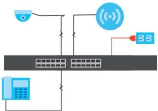
The following example figure shows a Switch supplying PoE (Power over Ethernet) to Powered Devices (PDs) such as an IP camera, a wireless router, an IP telephone and a general outdoor router that are not within reach of a power outlet.
Figure 1 Powered Device Example
flowchart
graph TD
    A["Central Server"] --> B["Mobile Phone"]
    A --> C["Wireless Signal"]
    A --> D["Network Port"]
    B --> E["Data Bus"]
    C --> F["Data Bus"]
    D --> G["Data Bus"]
The PoE function is available for the GS1100-10HP.
Ports 1 to 8 on the GS1100-10HP support both the IEEE 802.3af Power over Ethernet and IEEE 802.3at High Power over Ethernet standards. The ports supply power of up to 30W per Ethernet port and up to the total PoE power budget per Switch.
The Switch is Power Sourcing Equipment (PSE) because it provides a source of power via its Ethernet ports. A powered device (PD) is a device such as an access point or an IP phone, that supports PoE (Power over Ethernet) so that it can receive power from another device through a 10/100/1000 Mbps Ethernet port.
In the figure above, the IP camera and IP phone get their power directly from the Switch. Aside from minimizing the need for cables and wires, PoE removes the hassle of trying to find a nearby electric outlet to power up devices.
1.3.2 Backbone Example Application
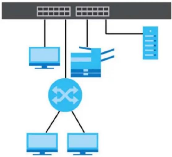
The Switch is an ideal solution for small networks where rapid growth can be expected in the near future. The Switch can be used standalone for a group of heavy traffic users. You can connect computers and servers directly to the Switch's port or connect other switches to the Switch.
In this example, all computers can share high-speed applications on the server. To expand the network, simply add more networking devices such as switches, routers, computers, print servers, and so on.
Figure 2 Backbone Application
flowchart
graph TD
    A["Server"] --> B["Client"]
    C["Client"] --> D["Switch"]
    E["Client"] --> D
    F["Client"] --> D
    G["Client"] --> D
    H["Client"] --> D
    I["Client"] --> D
    J["Client"] --> D
    K["Client"] --> D
    L["Client"] --> D
    M["Client"] --> D
    N["Client"] --> D
    O["Client"] --> D
    P["Client"] --> D
    Q["Client"] --> D
    R["Client"] --> D
    S["Client"] --> D
    T["Client"] --> D
    U["Client"] --> D
    V["Client"] --> D
    W["Client"] --> D
    X["Client"] --> D
    Y["Client"] --> D
    Z["Client"] --> D
1.3.3 Bridging or Fiber Uplink Example Application
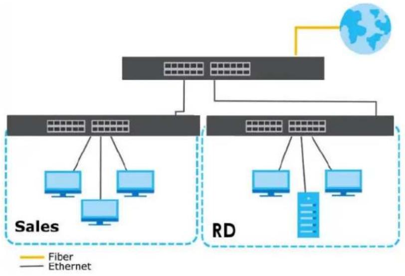
In this example, the Switch connects different company departments (RD and Sales) to the corporate backbone. It can alleviate bandwidth contention and eliminate server and network bottlenecks. All users that need high bandwidth can connect to high-speed department servers via the Switch. You can provide a super-fast uplink connection by using a Gigabit Ethernet or SFP port on the Switch.
Figure 3 Bridging Example Application
flowchart
graph TD
    A["Network"] --> B["Sales"]
    A --> C["RD"]
    B --> D["Computer 1"]
    B --> E["Computer 2"]
    B --> F["Computer 3"]
    C --> G["Computer 4"]
    C --> H["Computer 5"]
    C --> I["Computer 6"]
    D --> J["Data Tower"]
    E --> J
    F --> J
    G --> J
    H --> J
    I --> J
    J --> K["Fiber"]
    J --> L["Ethernet"]
CHAPTER 2
Hardware Installation and
Connection
2.1 Installation Scenarios
This chapter shows you how to install and connect the Switch.
The Switch can be:
- Placed on a desktop.
• Wall-mounted on a wall. - Rack-mounted on a standard EIA rack.
See Table 1 on page 8 for the comparison table of the hardware installation methods for each model.
2.1.1 Before Using the Switch
Please observe the following before using the Switch:
- It is recommended to ask an authorized technician to attach the Switch on a desk or to the rack or wall. Use the proper screws to prevent damage to the Switch. See the Installation Requirements sections in this chapter to know the types of screws and screw drivers for each mounting method.
- Make sure there is at least 2cm of clearance on the top and bottom of the Switch, and at least 5cm of clearance on all four sides of the Switch. This allows air circulation for cooling.
- Do NOT block the ventilation holes nor store cables or power cords on the Switch. Allow clearance for the ventilation holes to prevent your Switch from overheating. This is especially crucial when your Switch does not have fans. Overheating could affect the performance of your Switch, or even damage it.
- The surface of the Switch could be hot when it is functioning. Do NOT put your hands on it. You may get burned. This could happen especially when you are using a fanless Switch.
- The Switches with fans are not suitable for use in locations where children are likely to be present.
To start using the Switch, simply connect the power cables and turn it on.
2.2 Hardware Installation
See the following table for a comparison of the hardware installation methods of each GS1100 model:
Table 2 GS1100 Series Installation Comparison Table
| MODEL FEATURE | GS1100-10HP | GS1100-16 | GS1100-24E | GS1100-24 |
| Desktop Device | √ | √ | √ | |
| Wall-mountable | √ | √ | √ | |
| Rack-mountable | √ | √ | √ |
For GS1100-10HP, GS1100-16 and GS110-24E, you can place the Switch directly on top of your desk or have it wall-mounted. For GS1100-16, GS1100-24E and GS110-24, the size is suitable for rack-mounting and you can refer to Section 2.5 on page 16 for instruction. Take note of the following:
- The Switch should be placed on a desk that has a level surface and that is able to support the weight of the Switch.
To start using it, simply connect the power cables and turn on the Switch.
2.3 Desktop Installation Procedure
1 Make sure the Switch is clean and dry.
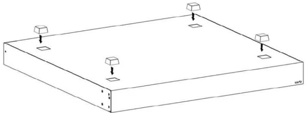
2 Remove the adhesive backing from the rubber feet.
3 Attach the rubber feet to each corner on the bottom of the Switch. These rubber feet help protect the Switch from shock or vibration and ensure space between devices when stacking.
Figure 4 Attaching Rubber Feet
natural_image
Isometric line drawing of a rectangular base with four square supports and three downward arrows indicating downward force or movement (no text or symbols)4 Set the Switch on a smooth, level surface strong enough to support the weight of the Switch and the connected cables. Make sure there is a power outlet nearby.
Cautions:
- Avoid stacking fanless Switches to prevent overheating.
- Ensure enough clearance around the Switch to allow air circulation for cooling.
- Do NOT remove the rubber feet as it provides space for air circulation.
2.4 Wall Mounting
The Switch can be mounted on a wall (see Table 1 on page 8). You may need screw anchors if mounting on a concrete or brick wall.
Do the following to attach your Switch to a wall.
See Table 3 on page 14 for how far apart to place the screws.
Table 3 Distance between the centers of the holes for wall mounting
| MODEL DISTANCE | |
| GS1100-10HP 176mm | |
| GS1100-16 148 mm | |
| GS1100-24E 120 mm |
2.4.1 Installation Requirements
• Distance above the floor: At least 1.8 m (5.9 feet)
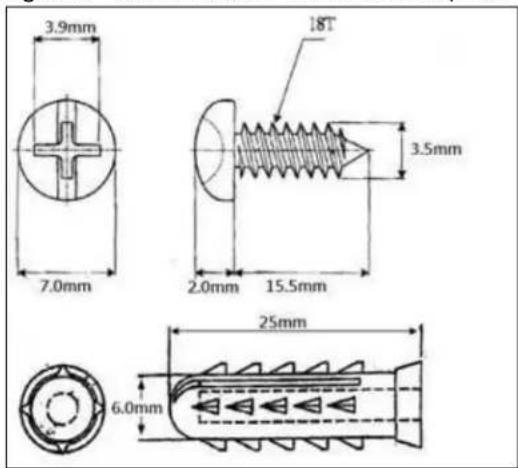
- Two M4 screws and a #2 Philips screwdriver
- Two screw anchors (optional)
Figure 5 GS1100-10HP screw specs
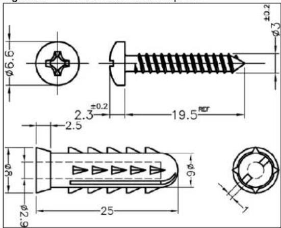
Figure 6 GS1100-16/GS1100-24E screw specs
1 Select a position free of obstructions on a wall strong enough to hold the weight of the Switch.
2 Mark two holes on the wall at the appropriate distance apart for the screws.
WARNING! Be careful to avoid damaging pipes or cables located inside the wall when drilling holes for the screws.
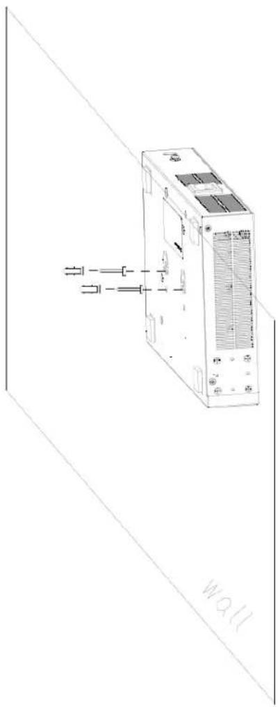
3 If using screw anchors, drill two holes for the screw anchors into the wall. Push the anchors into the full depth of the holes, then insert the screws into the anchors. Do NOT insert the screws all the way in - leave a small gap of about 0.5 cm.
If not using screw anchors, use a screwdriver to insert the screws into the wall. Do NOT insert the screws all the way in – leave a gap of about 0.5 cm.
4 Make sure the screws are fastened well enough to hold the weight of the Switch with the connection cables.
5 Align the holes on the back of the Switch with the screws on the wall. Hang the Switch on the screws.
Note: Make sure there is enough clearance between the wall and the Switch to allow ventilation.
natural_image
Line drawing of a server rack unit with indicator lights and ventilation slots (no text or symbols)WARNING! The Switch should be wall-mounted horizontally, and make sure the front panel is facing down. The Switch's side panels with ventilation slots should not be facing up or down as this position is less safe.
2.5 Rack Mounting
The Switch can be mounted on an EIA standard size, 19-inch rack or in a wiring closet with other equipment (see Table 1 on page 8). Follow the steps below to mount your Switch on a standard EIA rack using a rack-mounting kit.
Note: Make sure there is enough clearance between each equipment on the rack for air circulation.
2.5.1 Installation Requirements
- Two mounting brackets.
- Eight M3 flat head screws and a #2 Philips screwdriver.
- Four M5 flat head screws and a #2 Philips screwdriver.
2.5.2 Precautions
- Make sure the rack will safely support the combined weight of all the equipment it contains. The maximum weight a bracket can hold is 21.5 kg.
- Make sure the position of the Switch does not make the rack unstable or top-heavy. Take all necessary precautions to anchor the rack securely before installing the unit.
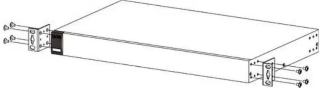
2.5.3 Attaching the Mounting Brackets to the Switch
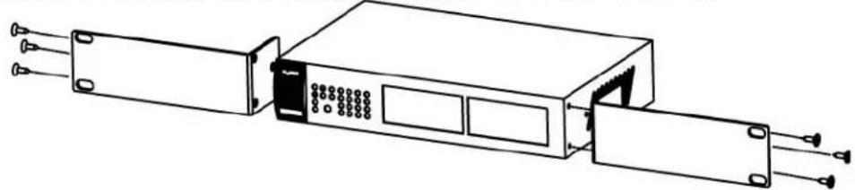
1 Position a mounting bracket on one side of the Switch, lining up the four screw holes on the bracket with the screw holes on the side of the Switch.
Figure 7 Attaching the Mounting Brackets (GS1100-16 and GS1100-24E)
natural_image
Technical line drawing of an electronic device with ports and connectors (no text or symbols)Figure 8 Attaching the Mounting Brackets (GS1100-24)
natural_image
Technical line drawing of a mechanical or electronic component with ports and connectors (no text or symbols)2 Using a #2 Philips screwdriver, install the M3 flat head screws through the mounting bracket holes into the Switch.
3 Repeat steps 1 and 2 to install the second mounting bracket on the other side of the Switch.
4 You may now mount the Switch on a rack. Proceed to the next section.
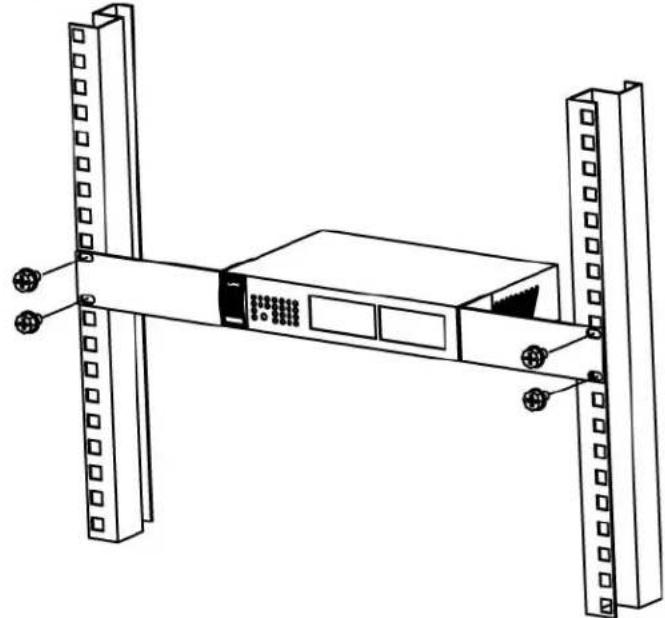
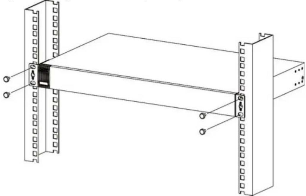
2.5.4 Mounting the Switch on a Rack
1 Position a mounting bracket (that is already attached to the Switch) on one side of the rack, lining up the two screw holes on the bracket with the screw holes on the side of the rack.
Figure 9 Mounting the Switch on a Rack (GS1100-16 and GS1100-24E)
natural_image
Technical line drawing of a server rack with two vertical supports and a central unit (no text or symbols)Figure 10 Mounting the Switch on a Rack (GS1100-24)
natural_image
Technical line drawing of a mechanical assembly with two vertical plates and a central rod (no text or symbols)2 Using a #2 Philips screwdriver, install the M5 flat head screws through the mounting bracket holes into the rack.
Note: Make sure you tighten all the four screws to prevent the Switch from getting slanted.
3 Repeat steps 1 and 2 to attach the second mounting bracket on the other side of the rack.
CHAPTER 3
Hardware Panels
This chapter describes the front panel and rear panel of the Switch and shows you how to make the hardware connections.
3.1 Front Panel
You can use either crossover or straight-through cables for all the ports.
The front panel of the Switch includes the auto-negotiating 10 Base-T/100 Base-TX/1000 Base-T RJ-45 ports and the LEDs.
The GS1100-24 and GS1100-10HP have two SFP slots. Refer to Section 3.1.5 on page 21 for more information.
The following figures show the front panels of the Switch.
Figure 11 Front Panel
GS1100-10HP

natural_image
Front view of a network switch device labeled 'ZYXEL 08100-24' with multiple Ethernet ports and indicator lights (no readable text beyond branding)You can use unshielded twisted pair (UTP) or shielded twisted-pair (STP) Ethernet cables for RJ-45 ports. The following table describes the types of network cable used for the different connection speeds.
Table 4 Network Cable Types
| SPEED NETWORK | CABLE TYPE |
| 10 Mbps Category | 3, 4 or 5 UTP/STP |
| 100 Mbps Category | 5 UTP/STP |
| 1000 Mbps Category | 5e, 6 UTP/STP |
3.1.1 RJ-45 Auto-negotiating Ports
The 10 Base-T/100 Base-TX/1000 Base-T RJ-45 ports are auto-negotiating and auto-crossover.
An auto-negotiating port can detect and adjust to the optimum Ethernet speed (10/100/1000 Mpbs) and duplex mode (full duplex or half duplex) of the connected device.
An auto-crossover (auto-MDI/MDI-X) port automatically works with a straight-through or crossover Ethernet cable.
3.1.2 IEEE 802.3az EEE
The Switch supports the IEEE 802.3az EEE (Energy Efficient Ethernet) standard to help reduce power consumption. This allows the Switch to go into power saving mode and switch off part of receive and transmit circuitry when it is not transmitting or receiving data through an Ethernet connection.
An EEE-enabled device initiates Low Power Idle (LPI) signals to negotiate and wake up the remote device when there is data to be transmitted. To use EEE, both devices should be EEE compliant.
EEE is configured on a per-system basis in the Switch. If one of the networking devices that connect to the Switch does not support EEE, EEE may not work in the Switch to save power.
Press the IEEE 802.3az EEE ON/OFF button on the GS1100-10HP to turn on the EEE feature. Disable it if you don't want the network performance to be impacted due to the latency from the additional time required for the sleep and wake transition or if the remote side does not support it.
Note: Only the GS1100-10HP has the IEEE 802.3az EEE button. For the GS1100-16/24E/24, the IEEE 802.3az EEE feature is enabled by default.
3.1.3 Gigabit Ethernet Ports
The Switch has 1000Base-T auto-negotiating, auto-crossover Ethernet ports. In 10/100/1000 Mbps Gigabit, the speed can be 10 Mbps, 100 Mbps or 1000 Mbps and the duplex mode can be half duplex or full duplex.
An auto-negotiating port can detect and adjust to the optimum Ethernet speed (10/100/1000 Mbps) and duplex mode (full duplex) of the connected device.
An auto-crossover (auto-MDI/MDI-X) port automatically works with a straight-through or crossover Ethernet cable.
When auto-negotiation is turned on, an Ethernet port negotiates with the peer automatically to determine the connection speed and duplex mode. If the peer Ethernet port does not support auto-negotiation or turns off this feature, the Switch determines the connection speed by detecting the signal on the cable. When the Switch's auto-negotiation is turned off, an Ethernet port uses the pre-configured speed and duplex mode when making a connection, thus requiring you to make sure that the settings of the peer Ethernet port are the same in order to connect.
All ports support auto-crossover, that is auto-MDIX ports (Media Dependent Interface Crossover), so you may use either a straight-through Ethernet cable or crossover Ethernet cable for all Gigabit port connections. Auto-crossover ports automatically sense whether they need to function as crossover or straight ports, so crossover cables can connect both computers and switches or hubs.
3.1.4 PoE (GS1100-10HP)
The Switch supports the IEEE 802.3af Power over Ethernet (PoE), IEEE 802.3at Power over Ethernet (PoE) plus. The Switch is a Power Sourcing Equipment (PSE) because it provides a source of power through its Ethernet ports. Each device that receives power through an Ethernet port is a Powered Device (PD).
3.1.5 SFP Slots (GS1100-24 and GS1100-10HP)
These are slots for SFP (Small Form-Factor Pluggable) transceivers. A transceiver is a single unit that houses a transmitter and a receiver. The Switch does not come with transceivers. You must use transceivers that comply with the Small Form-factor Pluggable (SFP) Transceiver MultiSource Agreement (MSA). See the SFF committee's INF-8074i specification Rev 1.0 for details.
You can change transceivers while the Switch is operating. You can use different transceivers to connect to Ethernet switches with different types of fiber or even copper cable connectors.
• Type: SFP connection interface
- Connection speed: 100/1000 Mbps
WARNING! To avoid possible eye injury, do not look into an operating fiber module's connectors.
HANDLING! All transceivers are static sensitive. To prevent damage from electrostatic discharge (ESD), it is recommended you attach an ESD preventive wrist strap to your wrist and to a bare metal surface when you install or remove a transceiver.
STORAGE! All modules are dust sensitive. When not in use, always keep the dust plug on. Avoid getting dust and other contaminant into the optical bores, as the optics do not work correctly when obstructed with dust.
3.1.5.1 Transceiver Installation
Use the following steps to install a transceiver.
1 Attach an ESD preventive wrist strap to your wrist and to a bare metal surface.
2 Align the transceiver in front of the slot opening.
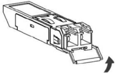
3 Make sure the latch is in the lock position (latch styles vary), then insert the transceiver into the slot with the exposed section of PCB board facing down.
4 Press the transceiver firmly until it clicks into place.
5 The Switch automatically detects the installed transceiver. Check the LEDs to verify that it is functioning properly.
6 Remove the dust plugs from the transceiver and cables (dust plug styles vary).
7 Identify the signal transmission direction of the fiber cables and the transceiver. Insert the fiber cable into the transceiver.
Figure 12 Latch in the Lock Position
natural_image
Technical line drawing of a mechanical component with no visible text or symbolsFigure 13 Transceiver Installation Example
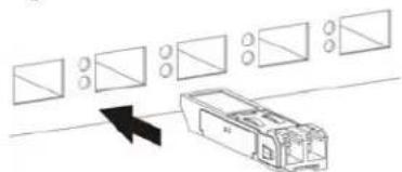
natural_image
Diagram showing a device with multiple rectangular components and an arrow pointing to it (no text or symbols present)Figure 14 Connecting the Fiber Cables
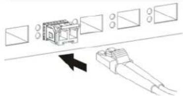
natural_image
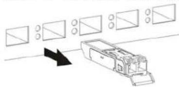
Diagram showing a device with rectangular components and directional arrows indicating movement or assembly (no text or symbols present)3.1.5.2 Transceiver Removal
Use the following steps to remove an SFP transceiver.
1 Attach an ESD preventive wrist strap to your wrist and to a bare metal surface on the chassis.
2 Remove the fiber cables from the transceiver.
3 Pull out the latch and down to unlock the transceiver (latch styles vary).
Note: Make sure the transceiver's latch is pushed all the way down, so the transceiver can be pulled out successfully.
4 Pull the latch, or use your thumb and index finger to grasp the tabs on both sides of the transceiver, and carefully slide it out of the slot.
Note: Do NOT pull the transceiver out by force. You could damage it. If the transceiver will not slide out, grasp the tabs on both sides of the transceiver with a slight up or down motion and carefully slide it out of the slot. If unsuccessful, contact Zyxel Support to prevent damage to your Switch and transceiver.
5 Insert the dust plug into the ports on the transceiver and the cables.
Figure 15 Removing the Fiber Cables
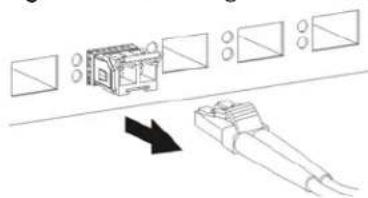
Figure 16 Opening the Transceiver's Latch Example
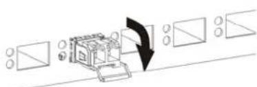
Figure 17 Transceiver Removal Example
natural_image
Diagram showing a vehicle with multiple rectangular boxes and circular components, connected by an arrow indicating direction (no text or symbols present)3.2 Rear Panel
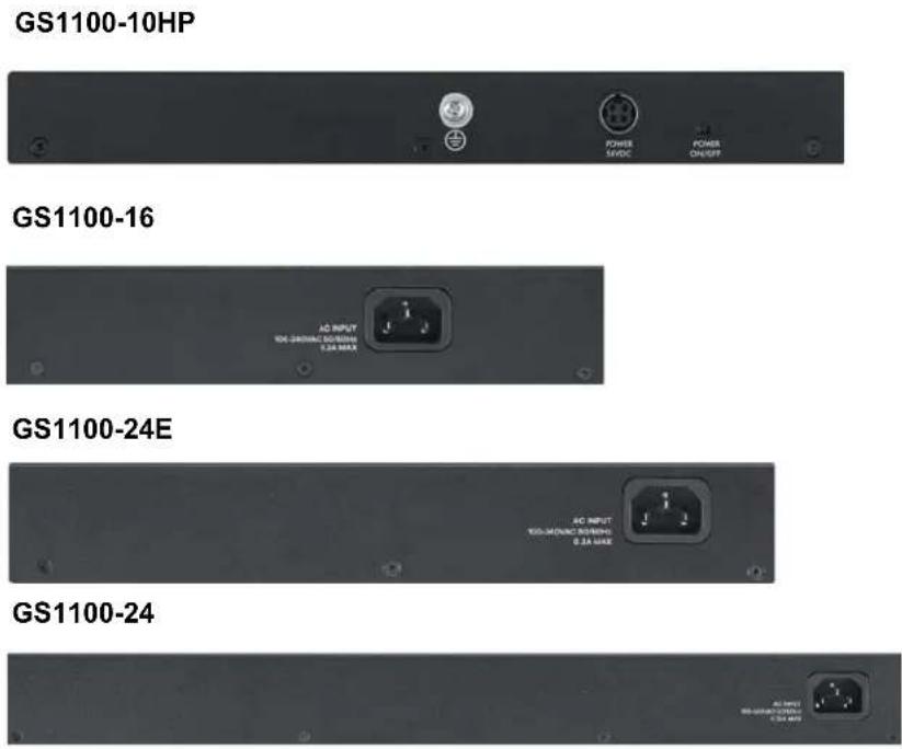
The following figures show the rear panels of the Switch. The rear panels contain:
The power receptacle is located on the rear panel of the Switch. Refer to the power supply requirements on the panel.
Figure 18 Rear Panel
3.2.1 Grounding (GS1100-10HP)
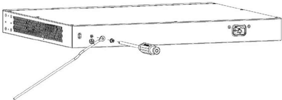
Grounding is a safety measure to direct excess electric charge to the ground. It prevents damage to the Switch, and protects you from electrocution. Use the grounding screw on the rear panel and the ground wire of the AC power supply to ground the Switch.
The grounding terminal and AC power ground where you install the Switch must follow your country's regulations. Qualified service personnel must ensure the building's protective earthing terminals are valid terminals.
Installation of Ethernet cables must be separate from AC power lines. To avoid electric surge and electromagnetic interference, use a different electrical conduit or raceway (tube/trough or enclosed conduit for protecting electric wiring) that is 15 cm apart, or as specified by your country's electrical regulations.
Any device that is located outdoors and connected to this product must be properly grounded and surge protected. To the extent permissible by your country's applicable law, failure to follow these guidelines could result in damage to your Switch which may not be covered by its warranty.
Note: The specification for surge or ESD protection assumes that the Switch is properly grounded.
1 Remove the M4 ground screw from the Switch's rear panel.
2 Secure a green or yellow ground cable (16 AWG or smaller) to the Switch's rear panel using the M4 ground screw.
Figure 19 Grounding
natural_image
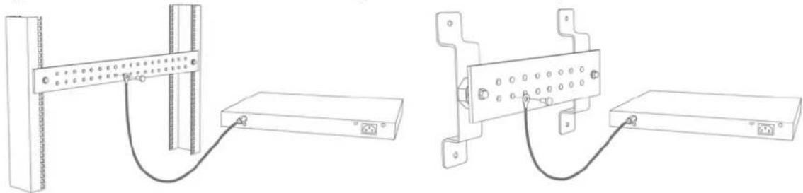
Line drawing of a server rack with ports and connectors (no text or symbols)3 Attach the other end of the ground cable to a grounding bar located on the rack where you install the Switch or to an on-site grounding terminal.
Figure 20 Attach Ground Cable to Grounding Bar or On-site Grounding Terminal
natural_image
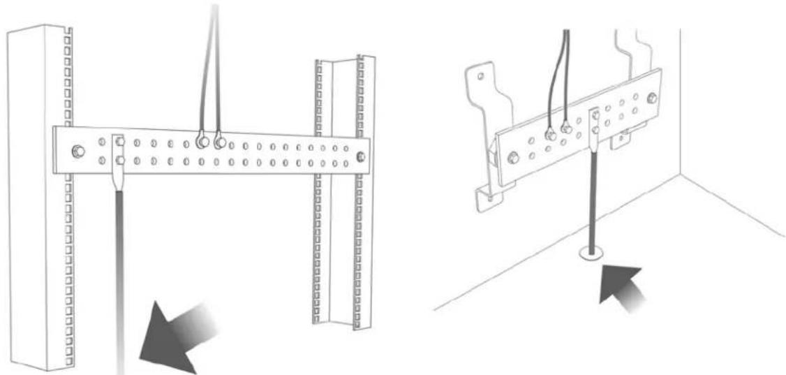
Technical line drawings of two electronic device setups with connectors and wiring (no text or symbols)4 The grounding terminal of the server rack or on-site grounding terminal must also be grounded and connected to the building's main grounding electrode. Make sure the grounding terminal is connected to the buildings grounding electrode and has an earth resistance of less than 10 ohms, or according to your country's electrical regulations.
Figure 21 Connecting to the Building's Main Grounding Electrode
natural_image
Technical line drawing showing two installation methods: one with a vertical rod and cable, the other with a horizontal rod and cable (no text or symbols present)If you are uncertain that suitable grounding is available, contact the appropriate electrical inspection authority or an electrician.
This device must be grounded. Do this before you make other connections.
3.2.2 Power Connection
Note: Make sure you are using the correct power source as shown on the panel.
GS1100-10HP: Connect the supplied power adapter to the power receptacle on the rear panel. Then use the included power cord to connect the power adapter to an appropriate power source. Set the power switch to the ON position.
GS1100-16/24E/24: To connect power to the Switch, insert the female end of the supplied power cord to the AC power receptacle on the rear panel. Connect the other end of the power cord to an appropriate power outlet.
3.2.3 LEDs
The LED Indicators give real-time information about the status of the Switch. The following table provides descriptions of the LEDs.
The following table describes the LEDs.
Table 5 LED Descriptions: GS1100-16/24/24E
| LED COLOR STATUS DESCRIPTION | ||
| PWR Green | On The Switch is receiving power from the power module in the power slot. | |
| Off The Switch is not receiving power from the power module in the power slot. | ||
| LINK/ACT | Green On The link to a 1000 Mbps Ethernet network is up. | |
| Blinking The Switch is transmitting/receiving to/from a 1000 Mbps Ethernet network. | ||
| The link to a 10 Mbps or a 100 Mbps Ethernet network is up. | ||
| Blinking | The Switch is transmitting/receiving to/from a 10 Mbps or a 100 Mbps Ethernet network. | |
| Off The portis not connected to an Ethernet network or the Switch is shut down. | ||
| Uplink Port LED (SFP) | Green On The port is connected to an Ethernet network at 1000 Mbps. | |
| Blinking The port is receiving or transmitting data at 1000 Mbps. | ||
| Amber On The link to a 100 Mbps Ethernet network is up. | ||
| Blinking The port is receiving or transmitting data at 100 Mbps. | ||
| Off The port is not connected to an Ethernet network or the Switch is shut down. | ||
Table 6 LED Descriptions: GS1100-10HP
| LED COLOR STATUS DESCRIPTION | |||||
| PWR Green | On The Switch | ch is receiving | power from the power module in the power slot. | ||
| Off The Switch | is not receiving power from the power module in the power slot. | ||||
| PoE MAX | Amber | On | Power supplied to the PoE port(s) has reached ninety-five percent of the power budget limit or has exceeded the total PoE power budget on the Switch. | ||
| Off Power supplied to the PoE port(s) is below the power budget limit. | |||||
| PoE 10/100/1000Base-T Ports | |||||
| Link/ACT (Left) | Green On | The link to a 1 Gbps Ethernet network is up. | |||
| Blinking The Switch is transmitting or receiving to/from a1 Gbps Ethernet network. | |||||
| Off The port is not connected to an Ethernet network. | |||||
| Amber On | The link to a 10 Mbps or a 100 Mbps Ethernet network is up. | ||||
| Blinking | The Switch is transmitting or receiving to/from a 10 Mbps or a 100 Mbps Ethernet network. | ||||
| Off The link to an Ethernet network is down. | |||||
| PoE Mode (Right) | Green | On | Power supplied to all PoE Ethernet ports meets the IEEE 802.3at standard | ||
| Off There is no power supplied. | |||||
| Amber | On | Power supplied to all PoE Ethernet ports meets the IEEE 802.3af standard. | |||
| Off There is no power supplied. | |||||
| SFP Green | On The uplink port is linking at 1 Gbps. | ||||
| Blinking The port is receiving or transmitting data at 1 Gbps. | |||||
| Off There is no link or port, or the uplink port is shut down. | |||||
| Amber On | The uplink port is linking at 100 Mbps. | ||||
| Blinking The port is receiving or transmitting data at 100 Mbps. | |||||
| Off There is no link or port, or the uplink port is shut down. | |||||
CHAPTER 4
Troubleshooting
This chapter offers some suggestions to solve problems you might encounter. The potential problems are divided into the following categories.
• Power, Hardware Connections, and LEDs
- Improper Network Cabling and Topology
4.1 Power, Hardware Connections, and LEDs
The Switch does not turn on. None of the LEDs turn on.
1 Make sure the Switch is turned on.
2 Make sure you are using the power adapter or cord included with the Switch.
3 Make sure the power adapter or cord is connected to the Switch and plugged in to an appropriate power source. Make sure the power source is turned on.
4 Turn the Switch off and on.
5 Disconnect and re-connect the power adapter or cord to the Switch.
6 If the problem continues, contact the vendor.
One of the LEDs does not behave as expected.
1 Make sure you understand the normal behavior of the LED. See Section 3.2.3 on page 26.
2 Check the hardware connections. See Section 3.1 on page 19.
3 Inspect your cables for damage. Contact the vendor to replace any damaged cables.
4 Turn the Switch off and on.
5 Disconnect and re-connect the power adapter or cord to the Switch.
6 If the problem continues, contact the vendor.
The PWR LED on the front panel does not light up.
- Check the connections from your Switch to the power source. Make sure you are using the supplied power cord and that you are using an appropriate power source. Refer to the product specifications.
- Make sure the power source is turned on and that the Switch is receiving sufficient power.
- If these steps fail to correct the problem, contact your local distributor for assistance.
The LNK/ ACT, 1G or 10/ 100 LED does not light up when a device is connected.
- Verify that the attached device(s) is turned on and properly connected to your Switch.
- Make sure the network adapters are working on the attached devices.
- Verify that proper network cable type is used and its length does not exceed 100 meters. For more information on network cable types, see Table 4 on page 20.
The PoE LED is off and/or power is not being supplied to my PoE-enabled device. (For GS1100-10HP)
- Check to see that the power adaptor is securely connected to the GS1100-10HP and an appropriate power source. Make sure the power source is on and functioning properly.
- Check that the Ethernet cables are connected properly and that you are using the correct type of Ethernet cable. Contact your local distributor if the problem persists.
4.2 Improper Network Cabling and Topology
Improper network cabling or topology setup is a common cause of poor network performance or even network failure.
Figure 22 Troubleshooting Improper Network Cabling and Topology
| PROBLEM CORRECTIVE ACTION | |
| Faulty cables | Using faulty network cables may affect data rates and have an impact on your network performance. Replace with new standard network cables. |
| Non-standard network cables | Non-standard cables may increase the number of network collisions and cause other network problems that affect your network performance. Refer to Table 4 on page 20 for more information on network cable types. |
| Cabling Length | If you use longer cables than are needed, transmission quality may be affected.The network cables should not be longer than the limit of 100 meters. |
Figure 22 Troubleshooting Improper Network Cabling and Topology
| PROBLEM CORRECTIVE ACTION | |
| Too many hubs between the computers in the network | Too many hubs (or repeaters) between the connected computers in the network may increase the number of network collision or other network problems. Remove unnecessary hubs from the network. |
| A loop in the data path | A data path loop forms when there is more than one path or route between two networked computers. This results in broadcast storms that will severely affect your network performance.Make sure there are no loops in your network topology. |
APPENDIX A
Customer Support
In the event of problems that cannot be solved by using this manual, you should contact your vendor. If you cannot contact your vendor, then contact a Zyxel office for the region in which you bought the device.
See https://www.zyxel.com/homepage.shtml and also
https://www.zyxel.com/about_zyxel/zyxel_worldwide.shtml for the latest information.
Please have the following information ready when you contact an office.
Required Information
- Product model and serial number.
- Warranty Information.
- Date that you received your device.
- Brief description of the problem and the steps you took to solve it.
Corporate Headquarters (Worldwide)
Taiwan
• Zyxel Communications Corporation
- http://www.zyxel.com
Asia
China
• Zyxel Communications (Shanghai) Corp.
Zyxel Communications (Beijing) Corp.
Zyxel Communications (Tianjin) Corp.
- https://www.zyxel.com/cn/zh/
India
• Zyxel Technology India Pvt Ltd.
- https://www.zyxel.com/in/en/
Kazakhstan
• Zyxel Kazakhstan
- https://www.zyxel.kz
Korea
• Zyxel Korea Corp.
- http://www.zyxel.kr
Malaysia
• Zyxel Malaysia Sdn Bhd.
- http://www.zyxel.com.my
Pakistan
• Zyxel Pakistan (Pvt.) Ltd.
- http://www.zyxel.com.pk
Philippines
• Zyxel Philippines
- http://www.zyxel.com.ph
Singapore
• Zyxel Singapore Pte Ltd.
- http://www.zyxel.com.sg
Taiwan
• Zyxel Communications Corporation
- https://www.zyxel.com/tw/zh/
Thailand
• Zyxel Thailand Co., Ltd.
- https://www.zyxel.com/th/th/
Vietnam
• Zyxel Communications Corporation-Vietnam Office
- https://www.zyxel.com/vn/vi
Europe
Belarus
- Z y x e l B Y
- https://www.zyxel.by
Belgium
• Zyxel Communications B.V.
- https://www.zyxel.com/be/nl/
• Zyxel Communications A/S
- https://www.zyxel.com/dk/da/
Estonia
- Zyxel Estonia
- https://www.zyxel.com/ee/et/
Finland
• Zyxel Communications
- https://www.zyxel.com/fi/fi/
France
• Zyxel France
- https://www.zyxel.fr
Germany
• Zyxel Communications Italy
- https://www.zyxel.com/it/it/
Latvia
• Z y x e l L a t v i a
- https://www.zyxel.com/lv/lv/
Lithuania
• Zyxel Lithuaniaia
- https://www.zyxel.com/lt/lt/
Netherlands
- Zyxel Benelux
- https://www.zyxel.com/nl/nl/
Norway
• Zyxel Communications
- https://www.zyxel.com/no/no/
Poland
• Zyxel Communications Poland
- https://www.zyxel.com/pl/pl/
Romania
• Zyxel Romania
- https://www.zyxel.com/ro/ro
Russia
• Zyxel Communications Czech s.r.o. organizacna zlozka
- https://www.zyxel.com/sk/sk/
Spain
• Zyxel Turkey A.S.
- https://www.zyxel.com/tr/tr/
UK
• Zyxel Communications UK Ltd.
- https://www.zyxel.com/uk/en/
Ukraine
• Zyxel Ukraine
- http://www.ua.zyxel.com
South America
Argentina
• Zyxel Communications Corporation
- https://www.zyxel.com/co/es/
Brazil
• Zyxel Communications Brasil Ltda.
- https://www.zyxel.com/br/pt/
Colombia
• Zyxel Communications Corporation
- https://www.zyxel.com/co/es/
Ecuador
• Zyxel Communications Corporation
- https://www.zyxel.com/co/es/
South America
• Zyxel Communications Corporation
- https://www.zyxel.com/co/es/
Middle East
Israel
• Zyxel Communications Corporation
- http://il.zyxel.com/
Middle East
• Zyxel Communications Corporation
- https://www.zyxel.com/me/en/
North America
USA
- Zyxel Communications, Inc. – North America Headquarters
- https://www.zyxel.com/us/en/
Oceania
Australia
• Zyxel Communications Corporation
- https://www.zyxel.com/au/en/
Africa
South Africa
• Nology (Pty) Ltd.
- https://www.zyxel.com/za/en/
APPENDIX B
Legal Information
Copyright
Copyright © 2021 by Zyxel Communications Corporation.
The contents of this publication may not be reproduced in any part or as a whole, transcribed, stored in a retrieval system, translated into any language, or transmitted in any form or by any means, electronic, mechanical, magnetic, optical, chemical, photocopying, manual, or otherwise, without the prior written permission of Zyxel Communications Corporation.
Published by Zyxel Communications Corporation. All rights reserved.
Disclaimer
Zyxel does not assume any liability arising out of the application or use of any products, or software described herein. Neither does it convey any license under its patent rights nor the patent rights of others. Zyxel further reserves the right to make changes in any products described herein without notice. This publication is subject to change without notice.
Regulatory Notice and Statement (Class A)
Model List: GS1100-16, GS1100-24, GS1100-24E
United States of America

The following information applies if you use the product within USA area.
US Importer: Zyxel Communications, Inc, 1130 North Miller Street Anaheim, CA92806-2001, https://www.zyxel.com/us/en/
Federal Communications Commission (FCC) EMC Statement
- This device complies with Part 15 of FCC rules. Operation is subject to the following two conditions:
(1) This device may not cause harmful interference.
(2) This device must accept any interference received, including interference that may cause undesired operations.
- Changes or modifications not expressly approved by the party responsible for compliance could void the user's authority to operate the equipment.
- This equipment has been tested and found to comply with the limits for a Class A digital device, pursuant to part 15 of the FCC Rules. These limits are designed to provide reasonable protection against harmful interference when the equipment is operated in a commercial environment. This equipment generates, uses, and can radiate radio frequency energy and, if not installed and used in accordance with the instruction manual, may cause harmful interference to radio communications. Operation of this equipment in a residential area is likely to cause harmful interference in which case the user will be required to correct the interference at his own expense.
Canada
The following information applies if you use the product within Canada area.
Innovation, Science and Economic Development Canada ICES statement
CAN ICES-3 (A)/NMB-3(A)
European Union

The following information applies if you use the product within the European Union.
CE EMC statement
WARNING: This equipment is compliant with Class A of EN55032. In a residential environment this equipment may cause radio interference.
List of National Codes
| COUNTRY ISO 3166 2 LETTER CODE COUNTRY ISO 3166 2 LETTER CODE | |||
| Austria AT Liechtenstein LI | |||
| Belgium BE Lithuania LT | |||
| Bulgaria BG Luxembourg LU | |||
| Croatia HR Malta | MT | ||
| Cyprus | CY | Netherlands | NL |
| Czech Republic | CR Norway | NO | |
| Denmark | DK | Poland | PL |
| Estonia | EE Portugal | PT | |
| Finland | FI | Romania RO | |
| France | FR Serbia | RS | |
| Germany | DE Slovakia | SK | |
| Greece GR Slovenia | SI | ||
| Hungary | HU | Spain | ES |
| Iceland | IS | Sweden SE | |
| Ireland | IE | Switzerland | CH |
| Italy | IT | Turkey | TR |
| Latvia | LV United Kingdom | GB | |
Notices
CLASS 1 LASER PRODUCT
APPAREIL À LASER DE CLASS 1
PRODUCT COMPLIES WITH 21 CFR 1040.10 AND 1040.11.
PRODUIT CONFORME SELON 21 CFR 1040.10 ET 1040.11.
Safety Warnings
• To avoid possible eye injury, do NOT look into an operating fiber-optic module's connector.
- Do NOT use this product near water, for example, in a wet basement or near a swimming pool.
- Do NOT expose your device to dampness, dust or corrosive liquids.
- Do NOT store things on the device.
- Do NOT obstruct the device ventilation slots as insufficient airflow may harm your device. For example, do not place the device in an enclosed space such as a box or on a very soft surface such as a bed or sofa.
- Do NOT install, use, or service this device during a thunderstorm. There is a remote risk of electric shock from lightning.
- Connect ONLY suitable accessories to the device.
- Do NOT open the device or unit. Opening or removing covers can expose you to dangerous high voltage points or other risks. Only qualified service personnel should service or disassemble this device. Please contact your vendor for further information.
- Make sure to connect the cables to the correct ports.
- Place connecting cables carefully so that no one will step on them or stumble over them.
• Always disconnect all cables from this device before servicing or disassembling.
- Do NOT remove the plug and connect it to a power outlet by itself; always attach the plug to the power adaptor first before connecting it to a power outlet.
- Do NOT allow anything to rest on the power adaptor or cord and do NOT place the product where anyone can walk on the power adaptor or cord.
- Please use the provided or designated connection cables/power cables/adaptors. Connect it to the right supply voltage (for example, 110V AC in North America or 230V AC in Europe). If the power adaptor or cord is damaged, it might cause electrocution. Remove it from the device and the power source, repairing the power adapter or cord is prohibited. Contact your local vendor to order a new one.
- Do NOT use the device outside, and make sure all the connections are indoors. There is a remote risk of electric shock from lightning.
- CAUTION: RISK OF EXPLOSION IF BATTERY IS REPLACED BY AN INCORRECT TYPE, DISPOSE OF USED BATTERIES ACCORDING TO THE INSTRUCTION. Dispose them at the applicable collection point for the recycling of electrical and electronic device. For detailed information about recycling of this product, please contact your local city office, your household waste disposal service or the store where you purchased the product.
• Use ONLY power wires of the appropriate wire gauge for your device. Connect it to a power supply of the correct voltage.
- Fuse Warning! Replace a fuse only with a fuse of the same type and rating.
• The POE (Power over Ethernet) devices that supply or receive power and their connected Ethernet cables must all be completely indoors.
- The following warning statements apply, where the disconnect device is not incorporated in the device or where the plug on the power supply cord is intended to serve as the disconnect device,
- For PERMANENTLY CONNECTED DEVICES, a readily accessible disconnect device shall be incorporated external to the device;
- For PLUGGABLE DEVICES, the socket-outlet shall be installed near the device and shall be easily accessible.
- This device must be grounded by qualified service personnel. Never defeat the ground conductor or operate the device in the absence of a suitably installed ground conductor. Contact the appropriate electrical inspection authority or an electrician if you are uncertain that suitable grounding is available. If your device has an earthing screw (frame ground), connect the screw to a ground terminal using an appropriate AWG ground wire. Do this before you make other connections. If your device has no earthing screw, but has a 3-prong power plug, make sure to connect the plug to a 3-hole earthed socket.
- When connecting or disconnecting power to hot-pluggable power supplies, if offered with your system, observe the following guidelines:
- Install the power supply before connecting the power cable to the power supply.
- Unplug the power cable before removing the power supply.
- If the system has multiple sources of power, disconnect power from the system by unplugging all power cables from the power supply.
• CLASS 1 LASER PRODUCT (for products with mini-GBIC slots or laser products, such as fiber-optic transceiver and GPON products). - PRODUCT COMPLIES WITH 21 CFR 1040.10 AND 1040.11. (for products with mini-GBIC slots or laser products, such as fiber-optic transceiver and GPON products)
• APPAREIL À LASER DE CLASS 1 (for products with mini-GBIC slots or laser products, such as fiber-optic transceiver and GPON products).
• PRODUIT CONFORME SELON 21 CFR 1040.10 ET 1040.11. (for products with mini-GBIC slots or laser products, such as fiber-optic transceiver and GPON products)
Important Safety Instructions
Environment Statement
European Union – Disposal and Recycling Information
The symbol below means that according to local regulations your product and/or its battery shall be disposed of separately from domestic waste. If this product is end of life, take it to a recycling station designated by local authorities. At the time of disposal, the separate collection of your product and/or its battery will help save natural resources and ensure that the environment is sustainable development.
natural_image
Simple line drawing of a trash bin with two crossed lines indicating no waste or prohibition (no text or symbols)
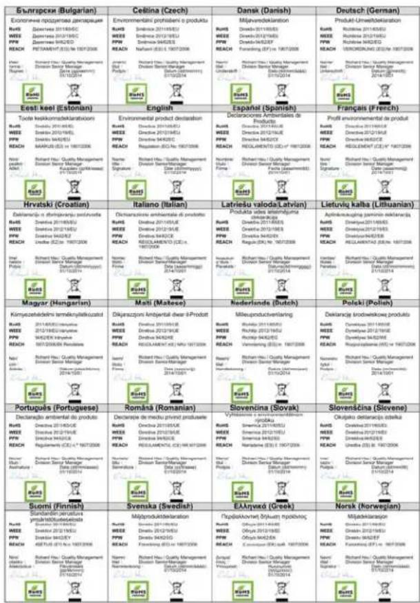
Environmental Product Declaration
台灣
以下訊息僅適用於產品銷售至台灣地區
Regulatory Notice and Statement (Class B)
Model List: GS1100-10HP
United States of America

The following information applies if you use the product within USA area.
US Importer: Zyxel Communications, Inc. 1130 North Miller Street Anaheim, CA92806-2001, https://www.zyxel.com/us/en/
Federal Communications Commission (FCC) EMC Statement
- This device complies with Part 15 of FCC rules. Operation is subject to the following two conditions:
(1) This device may not cause harmful interference.
(2) This device must accept any interference received, including interference that may cause undesired operations.
- Changes or modifications not expressly approved by the party responsible for compliance could void the user's authority to operate the equipment.
- This equipment has been tested and found to comply with the limits for a Class A digital device, pursuant to part 15 of the FCC Rules. These limits are designed to provide reasonable protection against harmful interference when the equipment is operated in a commercial environment. This equipment generates, uses, and can radiate radio frequency energy and, if not installed and used in accordance with the instruction manual, may cause harmful interference to radio communications. Operation of this equipment in a residential area is likely to cause harmful interference in which case the user will be required to correct the interference at his own expense.
Canada
The following information applies if you use the product within Canada area.
Innovation, Science and Economic Development Canada ICES statement
CAN ICES-3 (B)/NMB-3(B)
European Union

The following information applies if you use the product within the European Union.
List of National Codes
| COUNTRY ISO 3166 2 LETTER CODE COUNTRY ISO 3166 2 LETTER CODE | |||
| Austria AT Liechtenstein LI | |||
| Belgium BE Lithuania LT | |||
| Bulgaria BG Luxembourg LU | |||
| Croatia HR Malta | MT | ||
| Cyprus | CY | Netherlands | NL |
| Czech Republic | CR Norway | NO | |
| Denmark | DK | Poland | PL |
| Estonia | EE Portugal | PT | |
| Finland | FI | Romania RO | |
| France | FR Serbia | RS | |
| Germany | DE Slovakia | SK | |
| Greece GR Slovenia | SI | ||
| Hungary | HU | Spain | ES |
| Iceland | IS | Sweden SE | |
| Ireland | IE | Switzerland | CH |
| Italy | IT | Turkey | TR |
| Latvia | LV United Kingdom | GB | |
Safety Warnings
- To avoid possible eye injury, do NOT look into an operating fiber-optic module's connector.
- Do NOT use this product near water, for example, in a wel basement or near a swimming pool.
- Do NOT expose your device to dampness, dust or corrosive liquids.
- Do NOT store things on the device.
- Do NOT obstruct the device ventilation slots as insufficient airflow may harm your device. For example, do not place the device in an enclosed space such as a box or on a very soft surface such as a bed or sofa.
- Do NOT install, use, or service this device during a thunderstorm. There is a remote risk of electric shock from lightning.
- Connect ONLY suitable accessories to the device.
- Do NOT open the device or unit. Opening or removing covers can expose you to dangerous high voltage points or other risks. Only qualified service personnel should service or disassemble this device. Please contact your vendor for further information.
- Make sure to connect the cables to the correct ports.
- Place connecting cables carefully so that no one will step on them or stumble over them.
• Always disconnect all cables from this device before servicing or disassembling.
- Do NOT remove the plug and connect it to a power outlet by itself; always attach the plug to the power adaptor first before connecting it to a power outlet.
- Do NOT allow anything to rest on the power adaptor or cord and do NOT place the product where anyone can walk on the power adaptor or cord.
- Please use the provided or designated connection cables/power cables/adaptors. Connect it to the right supply voltage (for example, 110V AC in North America or 230V AC in Europe). If the power adaptor or cord is damaged, it might cause electrocution. Remove it from the device and the power source, repairing the power adapter or cord is prohibited. Contact your local vendor to order a new one.
- Do NOT use the device outside, and make sure all the connections are indoors. There is a remote risk of electric shock from lightning.
- CAUTION: RISK OF EXPLOSION IF BATTERY IS REPLACED BY AN INCORRECT TYPE, DISPOSE OF USED BATTERIES ACCORDING TO THE INSTRUCTION. Dispose them at the applicable collection point for the recycling of electrical and electronic device. For detailed information about recycling of this product, please contact your local city office, your household waste disposal service or the store where you purchased the product.
• Use ONLY power wires of the appropriate wire gauge for your device. Connect it to a power supply of the correct voltage.
- Fuse Warning! Replace a fuse only with a fuse of the same type and rating.
• The POE (Power over Ethernet) devices that supply or receive power and their connected Ethernet cables must all be completely indoors.
- The following warning statements apply, where the disconnect device is not incorporated in the device or where the plug on the power supply cord is intended to serve as the disconnect device.
- For PERMANENTLY CONNECTED DEVICES, a readily accessible disconnect device shall be incorporated external to the device;
- For PLUGGABLE DEVICES, the socket-outlet shall be installed near the device and shall be easily accessible.
- This device must be grounded by qualified service personnel. Never defeat the ground conductor or operate the device in the absence of a suitably installed ground conductor. Contact the appropriate electrical inspection authority or an electrician if you are uncertain that suitable grounding is available.
- When connecting or disconnecting power to hot-pluggable power supplies, if offered with your system, observe the following guidelines:
- Install the power supply before connecting the power cable to the power supply.
- Unplug the power cable before removing the power supply.
- If the system has multiple sources of power, disconnect power from the system by unplugging all power cables from the power supply.
• CLASS 1 LASER PRODUCT (for products with mini-GBIC slots or laser products, such as fiber-optic transceiver and GPON products).
- PRODUCT COMPLIES WITH 21 CFR 1040.10 AND 1040.11. (for products with mini-GBIC slots or laser products, such as fiber-optic transceiver and GPON products)
- APPAREIL À LASER DE CLASS 1 (for products with mini-GBIC slots or laser products, such as fiber-optic transceiver and GPON products).
- PRODUIT CONFORME SELON 21 CFR 1040.10 ET 1040.11. (for products with mini-GBIC slots or laser products, such as fiber-optic transceiver and GPON products)
Environment Statement
ErP (Energy-related Products)
All ZyXEL products put on the EU market in compliance with the requirement of the European Parliament and the Council published Directive 2009/125/EC establishing a framework for the setting of ecodesign requirements for energy-related products (recast), so called as “ErP Directive (Energy-related Products directive) as well as ecodesign requirement laid down in applicable implementing measures, power consumption has satisfied regulation requirements which are:
• Network standby power consumption < 12W and/or
- Off mode power consumption < 0.5 W and/or
- Standby mode power consumption < 0.5W .
Please refer to "Wireless" chapter for more details on Wireless settings.
Important Safety Instructions
1 Warning! Energy Hazard. Remove all metal jewelry, watches, and so on from your hands and wrists before serving this device.
2 Caution! The RJ-45 jacks are not used for telephone line connection.
3 Hazardous Moving Parts. Keep body parts away from fan blades.
4 Hot Surface. Do not touch.
Environment Statement
European Union – Disposal and Recycling Information
The symbol below means that according to local regulations your product and/or its battery shall be disposed of separately from domestic waste. If this product is end of life, take it to a recycling station designated by local authorities. At the time of disposal, the separate collection of your product and/or its battery will help save natural resources and ensure that the environment is sustainable development.
natural_image
Simple line drawing of a trash bin with crossed lines indicating no waste or restriction (no text or symbols)
Environmental Product Declaration

台灣
Various symbols are used in this product to ensure correct usage, to prevent danger to the user and others, and to prevent property damage. The meaning of these symbols are described below. It is important that you read these descriptions thoroughly and fully understand the contents.
Explanation of the Symbols
| SYMBOL EXPLANATION | ||
 | Alternating current (AC):AC is an electric current in which the flow of electric charge periodically reverses direction. | |
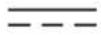 | Direct current (DC):DC if the unidirectional flow or movement of electric charge carriers. | |
 | Earth; ground:A wiring terminal intended for connection of a Protective Earthing Conductor. | |
 | Class II equipment:The method of protection against electric shock in the case of class II equipment is either double insulation or reinforced insulation. | |
Viewing Certifications
Go to http://www.zyxel.com to view this product's documentation and certifications.
Zyxel Limited Warranty
Zyxel warrants to the original end user (purchaser) that this product is free from any defects in material or workmanship for a specific period (the Warranty Period) from the date of purchase. The Warranty Period varies by region. Check with your vendor and/or the authorized Zyxel local distributor for details about the Warranty Period of this product. During the warranty period, and upon proof of purchase, should the product
have indications of failure due to faulty workmanship and/or materials, Zyxel will, at its discretion, repair or replace the defective products or components without charge for either parts or labor, and to whatever extent it shall deem necessary to restore the product or components to proper operating condition. Any replacement will consist of a new or re-manufactured functionally equivalent product of equal or higher value, and will be solely at the discretion of Zyxel. This warranty shall not apply if the product has been modified, misused, tampered with, damaged by an act of God, or subjected to abnormal working conditions.
Note
Repair or replacement, as provided under this warranty, is the exclusive remedy of the purchaser. This warranty is in lieu of all other warranties, express or implied, including any implied warranty of merchantability or fitness for a particular use or purpose. Zyxel shall in no event be held liable for indirect or consequential damages of any kind to the purchaser.
To obtain the services of this warranty, contact your vendor. You may also refer to the warranty policy for the region in which you bought the device at http://www.zyxel.com/web/support_warranty_info.php.
Registration
Register your product online at www.zyxel.com to receive email notices of firmware upgrades and related information.
Index
Numbers
10/100/1000 Mbps 8
A
air circulation for cooling 12
applications backbone 10 bridging 10 fiber uplink 10 PoE 9
authorized technician install the Switch 12
auto-MDIX port 21 auto-negotiating ports 20
C
Cabling Length 29
CE EMC statement 37
certifications viewing 45
clearance Switch installation 12
contact information customer support 31
copyright 37
crossover Ethernet cable 20
customer support 31
D
Data path loop 30 disclaimer 37
disposal and recycling information EU 39, 43
dual personality interface 23 dust plug 22
E
EEE 8, 20 electrical inspection authority 26 electrician 26 electrostatic discharge (ESD) 21 Energy Efficient Ethernet 20 Environment Statement 39, 43 Ethernet port auto-crossover 20 auto-negotiating 20
F
Faulty cables 29 FCC interference statement 37, 41 fiber cable connecting 22 removal 23 freestanding installation precautions 13 front panel 19
G
gigabit ports 20 grounding for safety 24
H
hardware installation 12
hardware overview 19
|
IEEE 802.3az 20
Innovation, Science and Economic Development Canada ICES statement 37, 41
installation
air circulation 12
desktop 13
rack-mounting 16
transceiver 21
wall mounting 14
installation requirements
rack-mounting 14
installation scenarios 12
L
LED Descriptions
LK/ACT 26
PWR 26
Low Power Idle 20
LPI signal 20
M
management method 9
MDIX (Media Dependent Interface Crossover) 21
mounting brackets 17
N
network applications 9
network cable
crossover 19
straight-through 19
Network Cable Types 20
Non-standard network cables 29
0
overheating
prevention 12
P
PD 10
power connections 26
power connector 26
power saving 20
powered device 10
product registration 46
R
rack-mounting 16
installation requirements 16
precautions 17
rear panel 23
registration
product 46
Regulatory Notice and Statement 37
rubber feet
attach 13
s
safety precautions
using the Switch 13
safety warnings 38, 42
screw anchors
using 15
SFP/SFP+ slot 21
Small Form-factor Pluggable (SFP) 21
straight-through Ethernet cable 20
Switch
fanless-type usage precaution 12
fan-type usage precaution 12
T
transceiver
connection speed 21
installation 21
removal 22
transceiver MultiSource Agreement (MSA) 21
transceivers 21
Troubleshooting
Improper Network Cabling and Topology 29
U
uplink connection
super-fast 10
v
ventilation holes 12
W
wall mounting 14
distance above the floor 14
distance between holes 14
warranty 45
note 46
- Document Conventions
- Warnings and Notes
- Warnings tell you about things that could harm you or your device.
- Syntax Conventions
- Icons Used in Figures
- Contents Overview
- User's Guide 7
- Table of Contents
- Part I: User's Guide....7
- Chapter 1
- Getting to Know Your Switch 8
- Chapter 2
- Hardware Installation and Connection 12
- Chapter 3
- Hardware Panels....19
- Chapter 4
- Troubleshooting....28
- PART I
- User's Guide
- Getting to Know Your Switch
- Introduction
- Features
- Example Applications
- PoE Example Application
- Backbone Example Application
- Bridging or Fiber Uplink Example Application
- Hardware Installation and
- Connection
- Installation Scenarios
- Before Using the Switch
- Hardware Installation
- Desktop Installation Procedure
- Cautions:
- Wall Mounting
- Installation Requirements
- WARNING! Be careful to avoid damaging pipes or cables located inside the wall when drilling holes for the screws.
- Rack Mounting
- Installation Requirements
- Precautions
- Attaching the Mounting Brackets to the Switch
- Mounting the Switch on a Rack
- Hardware Panels
- Front Panel
- RJ-45 Auto-negotiating Ports
- IEEE 802.3az EEE
- Gigabit Ethernet Ports
- PoE (GS1100-10HP)
- SFP Slots (GS1100-24 and GS1100-10HP)
- Transceiver Installation
- Transceiver Removal
- Rear Panel
- Grounding (GS1100-10HP)
- This device must be grounded. Do this before you make other connections.
- Power Connection
- LEDs
- Troubleshooting
- Power, Hardware Connections, and LEDs
- Improper Network Cabling and Topology
- APPENDIX A
- Customer Support
- Required Information
- Corporate Headquarters (Worldwide)
- Taiwan
- Asia
- China
- India
- Kazakhstan
- Korea
- Malaysia
- Pakistan
- Philippines
- Singapore
- Thailand
- Vietnam
- Europe
- Belarus
- Belgium
- Estonia
- Finland
- France
- Germany
- Latvia
- Lithuania
- Netherlands
- Norway
- Poland
- Romania
- Russia
- Spain
- UK
- Ukraine
- South America
- Argentina
- Brazil
- Colombia
- Ecuador
- Middle East
- Israel
- North America
- USA
- Oceania
- Australia
- Africa
- South Africa
- APPENDIX B
- Legal Information
- Copyright
- Disclaimer
- Regulatory Notice and Statement (Class A)
- United States of America
- Federal Communications Commission (FCC) EMC Statement
- Canada
- Innovation, Science and Economic Development Canada ICES statement
- European Union
- CE EMC statement
- Notices
- Safety Warnings
- Important Safety Instructions
- Environment Statement
- European Union – Disposal and Recycling Information
- 台灣
- Regulatory Notice and Statement (Class B)
- Environmental Product Declaration
- Viewing Certifications
- Zyxel Limited Warranty
- Note
- Registration
- Index
- Numbers
- A
- C
- D
- E
- F
- G
- H
- |
- L
- M
- N
- 0
- P
- R
- s
- T
- U
- v
- W
Brand : ZYXEL
Model : GS1100-24E
Category : Network switch