
GS1900-24 - Network switch ZYXEL - Free user manual and instructions
Find the device manual for free GS1900-24 ZYXEL in PDF.


| Product Type | Network Switch |
| Brand | ZyXEL |
| Model | GS1900-24 |
| Ports | 24 x Gigabit Ethernet (10/100/1000 Mbps) |
| Switching Capacity | 48 Gbps |
| MAC Address Table | 8K entries |
| Management | Web-based GUI, SNMP, CLI |
| VLAN Support | 802.1Q VLAN, up to 256 groups |
| Quality of Service | 802.1p, DiffServ, port-based QoS |
| Link Aggregation | Static LACP up to 8 groups |
| IGMP Snooping | v1, v2, v3 |
| Dimensions (W x D x H) | 440 x 131 x 44 mm (17.32 x 5.16 x 1.73 in) |
| Weight | 2.4 kg (5.29 lbs) |
| Power Supply | AC 100-240V, 50/60 Hz |
| Power Consumption | Less than 20W |
| Mounting | 19-inch rackmountable, wall-mountable |
| Operating Temperature | 0°C to 50°C (32°F to 122°F) |
| Safety | CE, FCC Class A |
| Cleaning Instructions | Use a dry, soft cloth. Do not use liquids or solvents. |
| Spare Parts / Repairability | No user-serviceable parts. Contact support for repairs. |
Frequently Asked Questions - GS1900-24 ZYXEL
User questions about GS1900-24 ZYXEL
0 question about this device. Answer the ones you know or ask your own.
Ask a new question about this device
Download the instructions for your Network switch in PDF format for free! Find your manual GS1900-24 - ZYXEL and take your electronic device back in hand. On this page are published all the documents necessary for the use of your device. GS1900-24 by ZYXEL.
USER MANUAL GS1900-24 ZYXEL
GbE Smart Managed Switch
Default Login Details
| IP Address http://192.168.1.1 (In-band ports) |
| User Name admin |
| Password 1234 |
Version 2.70 Edition 2, 04/2022

natural_image
Abstract geometric illustration of two green and white buildings with a crossed-line intersection (no text or symbols)IMPORTANT!
READ CAREFULLY BEFORE USE.
KEEP THIS GUIDE FOR FUTURE REFERENCE.
Screenshots and graphics in this book may differ slightly from your product due to differences in your product firmware or your computer operating system. Every effort has been made to ensure that the information in this manual is accurate.
Note: This guide is a reference for a series of products. Therefore some features or options in this guide may not be available in your product.
Note: It is recommended you use the Web Configurator to configure the Switch.
Related Documentation
- Online Help
Click the help link for a description of the fields in the Switch menus. - More Information
Go to https://businessforum.zyxel.com for product discussions. - Go to support.zyxel.com to find other information on the Switch.

Document Conventions
Warnings and Notes
These are how warnings and notes are shown in this guide.
Warnings tell you about things that could harm you or your device.
Note: Notes tell you other important information (for example, other things you may need to configure or helpful tips) or recommendations.
Syntax Conventions
- All models may be referred to as the "Switch" in this guide.
- Product labels, screen names, field labels and field choices are all in bold font.
- A right angle bracket (>) within a screen name denotes a mouse click. For example, Configuration > System > Information means you first click Configuration in the navigation panel, then the System sub menu and finally the Information tab to get to that screen.
Icons Used in Figures
Figures in this user guide may use the following generic icons. The Switch icon is not an exact representation of your device.
Switch Generic Switch Generic Router |  |  |
IP Camera Firewall Cell Tower |  |  |
Printer Server |  |
Contents Overview
User's Guide 16
Getting to Know Your Switch 17
Hardware Installation and Connection 25
Hardware Overview 31
ZON Utility 45
Web Configurator 50
Getting Started 61
Technical Reference 73
Monitor: System 74
Monitor: Port 77
Monitor: VLAN 86
Monitor: MAC Table 92
Monitor: Link Aggregation 95
Monitor: Loop Guard 97
Monitor: Multicast 100
Monitor: Spanning Tree 104
Monitor: LLDP 110
Monitor: Security 114
Monitor: Management 117
Configuration: System 120
Configuration: Port 125
Configuration: VLAN 138
Configuration: MAC Table 149
Configuration: Link Aggregation 152
Configuration: Loop Guard 158
Configuration: Mirror 161
Configuration: Time Range Group 164
Configuration: Multicast 169
Configuration: Spanning Tree 177
Configuration: LLDP 186
Configuration: QoS 198
Configuration: Security 207
Configuration: AAA 216
Configuration: Management 221
Maintenance 238
Troubleshooting 250
Table of Contents
Document Conventions ....3
Contents Overview 4
Table of Contents......5
Part I: User's Guide....16
Chapter 1 Getting to Know Your Switch ....17
1.1 Introduction ...... 17
1.1.1 Hardware Version Information 17
1.1.2 Hardware Comparison 19
1.2 Example Applications ...... 20
1.2.1 PoE Example Application 20
1.2.2 Backbone Example Application ...... 21
1.2.3 Bridging or Fiber-optic Uplink Example Application 21
1.2.4 Gigabit Ethernet to the Desktop 22
1.2.5 IEEE 802.1Q VLAN Application Example 22
1.2.6 IPv6 Support 23
1.3 Ways to Manage the Switch 23
1.4 Good Habits for Managing the Switch 24
Chapter 2 Hardware Installation and Connection ....25
2.1 Safety Precautions 25
2.2 Installation Scenarios 25
2.3 Desktop Installation Procedure 26
2.4 Wall Mounting 26
2.4.1 Wall-mounted Installation Requirement 27
2.5 Rack Mounting 28
2.5.1 Rack-mounted Installation Requirement 28
2.5.2 Attaching the Mounting Brackets to the Switch 29
2.5.3 Mounting the Switch on a Rack 29
Chapter 3 Hardware Overview....31
3.1 Front Panel Connections ...... 31
3.1.1 Ethernet Ports 33
3.1.2 SFP Slots 33
3.1.3 PoE Mode Button 36
3.2 Rear Panel 36
3.2.1 Grounding 38
3.2.2 Power Connection 40
3.3 LEDs 41
3.4 Resetting the Switch 43
3.5 Rebooting the Switch 44
Chapter 4
ZON Utility 45
4.1 Zyxel One Network (ZON) Utility 45
4.1.1 Requirements 45
4.1.2 Run the ZON Utility 46
Chapter 5
Web Configurator....50
5.1 Overview 50
5.2 Access 50
5.3 Navigating the Web Configurator 52
5.3.1 Title Bar 52
5.3.2 Navigation Panel 53
Chapter 6
Getting Started....61
6.1 Overview 61
6.1.1 What You Can Do in this Chapter 61
6.2 Getting Started 61
6.2.1 Wizard 62
Part II: Technical Reference....73
Chapter 7
Monitor: System....74
7.1 Overview 74
7.1.1 What You Can Do in this Chapter 74
7.2 IP Settings 74
7.2.1 IPv4 Settings 74
7.2.2 IPv6 Settings 75
7.3 Information 75
Chapter 8
Monitor: Port 77
8.1 Overview 77
8.1.1 What You Can Do in this Chapter 77
8.2 Port Settings 77
8.2.1 Status 77
8.2.2 Port Counters 78
8.2.3 Bandwidth Utilization 80
8.3 PoE Settings 81
8.4 Bandwidth Management 83
8.4.1 Bandwidth Control 83
8.5 Storm Control 84
Chapter 9
Monitor: VLAN....86
9.1 Overview 86
9.1.1 What You Can Do in this Chapter 86
9.2 VLAN Settings 86
9.2.1 VLAN 86
9.2.2 Port 87
9.2.3 VLAN Port 88
9.3 Guest VLAN 89
9.4 Voice VLAN 90
Chapter 10
Monitor: MAC Table 92
10.1 Overview 92
10.1.1 What You Can Do in this Chapter 93
10.2 MAC Table 93
Chapter 11
Monitor: Link Aggregation 95
11.1 Overview 95
11.1.1 What You Can Do in this Chapter 95
11.2 Link Aggregation 95
Chapter 12
Monitor: Loop Guard 97
12.1 Overview 97
12.1.1 What You Can Do in this Chapter 98
12.2 Loop Guard 98
Chapter 13
Monitor: Multicast....100
13.1 Overview 100
13.1.1 What You Can Do in this Chapter 100
13.2 IGMP Settings 100
13.2.1 VLAN 100
13.2.2 Statistics 101
13.2.3 Group 102
13.2.4 Router 103
Chapter 14
Monitor: Spanning Tree....104
14.1 Overview 104
14.1.1 What You Can Do in this Chapter 104
14.2 Spanning Tree 104
14.2.1 CIST Settings 104
14.2.2 CIST Port 105
14.2.3 MST Settings 106
14.2.4 MST Port 107
14.2.5 STP Statistics 108
Chapter 15
Monitor: LLDP 110
15.1 Overview 110
15.1.1 What You Can Do in this Chapter 110
15.2 LLDP Settings 110
15.2.1 Statistics Settings 110
15.2.2 Remote Information 11
15.2.3 Overloading 112
Chapter 16
Monitor: Security 114
16.1 Overview 114
16.1.1 What You Can Do in this Chapter 114
16.2 Port Security 114
16.3 802.1X Security Settings 115
16.3.1 Port Settings 115
16.3.2 Authenticated Hosts 116
Chapter 17
Monitor: Management 117
17.1 Overview 117
17.1.1 What You Can Do in this Chapter 117
17.2 Syslog 117
17.3 Error Disable 118
Chapter 18
Configuration: System 120
18.1 Overview 120
18.1.1 What You Can Do in this Chapter 120
18.2 IP Settings 120
18.2.1 IPv4 Settings 120
18.2.2 IPv6 Settings 121
18.3 Time 122
18.3.1 System Time Settings 122
18.3.2 SNTP Server Settings 123
18.4 Information 123
18.4.1 System Information Settings 123
Chapter 19
Configuration: Port 125
19.1 Overview 125
19.1.1 What You Can Do in this Chapter 125
19.2 Port Settings 125
19.2.1 Port 125
19.2.2 Port Edit 126
19.3 EEE Settings 127
19.3.1 EEE 127
19.3.2 EEE Edit 128
19.4 PoE Settings 129
19.4.1 Global Settings 129
19.4.2 Port Settings 129
19.4.3 PoE Edit 131
19.5 Bandwidth Management 134
19.5.1 Bandwidth Control 134
19.5.2 Port Rate Edit 135
19.6 Storm Control 135
19.6.1 Port Settings 136
19.6.2 Port Edit 136
Chapter 20
Configuration: VLAN 138
20.1 Overview 138
20.1.1 What You Can Do in this Chapter 138
20.2 VLAN Settings 139
20.2.1 VLAN 139
20.2.2 VLAN Add 139
20.2.3 Port Settings 140
20.2.4 Port Edit 141
20.2.5 VLAN Port 141
20.3 Guest VLAN 143
20.3.1 Global Settings 143
20.3.2 Port Settings 144
20.3.3 Port Edit 144
20.4 Voice VLAN 145
20.4.1 Global Settings 145
20.4.2 OUI Settings 146
20.4.3 OUI Add or Edit 147
20.4.4 Port Settings 147
20.4.5 Port Edit 148
Chapter 21
Configuration: MAC Table....149
21.1 Overview 149
21.1.1 What You Can Do in this Chapter 149
21.1.2 Static MAC 149
21.1.3 Static MAC Address 150
21.1.4 Filtering MAC Address 150
21.1.5 Filtering MAC Address (Add) 151
21.1.6 Dynamic Age 151
Chapter 22
Configuration: Link Aggregation....152
22.1 Overview 152
22.1.1 What You Can Do in this Chapter 152
22.2 Link Aggregation 152
22.2.1 Global Settings 152
22.2.2 LAG Management 153
22.2.3 LAG Management (Add) 154
22.2.4 LAG Port 155
22.2.5 LAG Port Edit 155
22.2.6 LACP Port 156
22.2.7 LACP Port Edit 157
Chapter 23
Configuration: Loop Guard 158
23.1 Overview 158
23.2 Loop Guard 158
23.2.1 Global Settings 158
23.2.2 Loop Guard Port 159
23.2.3 Port Edit 159
Chapter 24
Configuration: Mirror....161
24.1 Overview 161
24.2 Mirror Settings 161
24.2.1 Mirror 161
Chapter 25
Configuration: Time Range Group 164
25.1 Overview 164
25.1.1 What You Can Do 164
25.2 Time Range Group 164
25.2.1 Time Range Group Settings 164
25.2.2 Time Range Add 165
25.2.3 Time Range Edit 166
Chapter 26
Configuration: Multicast....169
26.1 Overview 169
26.2 IGMP Settings 169
26.2.1 Global Settings 169
26.2.2 VLAN Settings 170
26.2.3 Edit IGMP 171
26.2.4 Router Port 172
26.2.5 Add or Edit Router Port 172
26.2.6 Profile Settings 173
26.2.7 Add or Edit Profile 174
26.2.8 Throttling Settings 174
26.2.9 Edit Throttling 175
Chapter 27
Configuration: Spanning Tree ....177
27.1 Overview 177
27.2 Spanning Tree 177
27.2.1 Global Settings 177
27.2.2 STP Port 178
27.2.3 STP Port Edit 179
27.2.4 CIST Settings 180
27.2.5 CIST Port 181
27.2.6 CIST Port Edit 181
27.2.7 MST Settings 182
27.2.8 Add or Edit MST 183
27.2.9 MST Port Settings 183
27.2.10 MST Port Edit 184
Chapter 28
Configuration: LLDP 186
28.1 Overview 186
28.2 LLDP Settings 186
28.2.1 Global Settings 186
28.2.2 Port Settings 187
28.2.3 Port Edit 188
28.2.4 Local Information Settings 189
28.2.5 Local Information Edit 191
28.2.6 MED Network Policy 194
28.2.7 MED Network Policy Add or Edit 194
28.2.8 MED Port 196
28.2.9 MED Port Edit 196
Chapter 29
Configuration: QoS 198
29.1 Overview 198
29.2 General Settings 198
29.2.1 Port Settings 198
29.2.2 Port Edit 199
29.2.3 Queue Settings 200
29.2.4 CoS Mapping 201
29.2.5 DSCP Mapping 202
29.2.6 IP Precedence Mapping 203
29.3 Trust Mode 204
29.3.1 Global Settings 204
29.3.2 Port Settings 204
29.3.3 Trust Mode Edit 205
Chapter 30
Configuration: Security 207
30.1 Overview 207
30.2 Port Security 207
30.2.1 Global Settings 207
30.2.2 Port Settings 207
30.2.3 Port Edit 208
30.3 Port Isolation 209
30.3.1 Port Isolation Settings 209
30.3.2 Port Isolation Edit 210
30.4 802.1X Settings 210
30.4.1 Global Settings 210
30.4.2 Port Settings 211
30.4.3 Port Edit 212
30.5 DoS Settings 213
30.5.1 Global Settings 213
30.5.2 Port Settings 213
30.5.3 Port Edit 214
30.5.4 DoS Attack Types 215
Chapter 31
Configuration: AAA....216
31.1 Overview 216
31.2 Auth Method 216
31.2.1 Auth Method Settings 216
31.2.2 Auth Method Add or Edit 216
31.3 RADIUS Settings 217
31.3.1 RADIUS 217
31.3.2 RADIUS Add or Edit 218
31.4 TACACS+ Settings 219
31.4.1 TACACS+ 219
31.4.2 TACACS+ Add or Edit 219
Chapter 32
Configuration: Management....221
32.1 Overview 221
32.2 Syslog Settings 221
32.2.1 Global Settings 221
32.2.2 Local Settings 221
32.2.3 Local Add or Edit 222
32.2.4 Remote Settings 223
32.2.5 Remote Add or Edit 223
32.3 SNMP Settings 224
32.3.1 Global Settings 224
32.3.2 Community Settings 224
32.3.3 Community Add or Edit 225
32.3.4 Group Settings 225
32.3.5 Group Add or Edit 226
32.3.6 User Settings 227
32.3.7 User Add or Edit 228
32.3.8 Trap Settings 228
32.3.9 Trap Destination 229
32.3.10 Trap Destination Add or Edit 230
32.4 Error Disable 231
32.4.1 Error Disable Settings 231
32.5 HTTP/HTTPS 231
32.5.1 HTTP Settings 231
32.5.2 HTTPS Settings 232
32.6 TELNET/SSH 233
32.6.1 TELNET Settings 233
32.6.2 SSH Settings 233
32.7 Users Settings 234
32.7.1 Users 234
32.7.2 Users Add or Edit 234
32.8 Remote Access Control 235
32.8.1 Global Settings 235
32.8.2 Profile Add or Edit 236
Chapter 33
Maintenance 238
33.1 Firmware Upgrade 238
33.1.1 Overview 238
33.1.2 Upgrade the firmware from a file on a server 238
33.1.3 Upgrade the firmware from a file on your computer 239
33.2 Firmware Management 239
33.2.1 Overview 239
33.2.2 Select the Active Image 240
33.3 Backup a Configuration File 241
33.3.1 Overview 241
33.3.2 Back up configuration or log files to a server 242
33.3.3 Back up configuration or log files to your computer 242
33.4 Restore a Configuration File 242
33.4.1 Overview 242
33.4.2 Restore the configuration from a file on a server 243
33.4.3 Restore the configuration from a file on your computer 243
33.5 Manage Configuration Files 243
33.5.1 Overview 243
33.6 Reset to Factory Defaults 244
33.6.1 Overview 244
33.6.2 Reset the Switch to Factory Defaults 244
33.7 Network Diagnostics 245
33.7.1 Port Test 245
33.7.2 IPv4 Ping Test 245
33.7.3 IPv6 Ping Test 247
33.7.4 Trace Route 248
33.8 Reboot 249
Table of Contents
33.8.1 Overview 249
33.8.2 Reboot the Switch 249
Chapter 34
Troubleshooting....250
34.1 Power, Hardware Connections, and LEDs 250
34.2 Switch Access and Login 251
34.3 Switch Configuration 252
Appendix A Customer Support 253
Appendix B Legal Information 258
Index 265
PART I
User's Guide
CHAPTER 1
Getting to Know Your Switch
This chapter introduces the main features and applications of the Switch.
1.1 Introduction
The GS1900 series is a new generation Gigabit Ethernet (GbE) Web-Managed Switch.
1.1.1 Hardware Version Information
The GS1900 series have hardware revisions, and the major changes are:
- For the reset Switch back to factory default function, the RESET button is renamed to RESTORE to align with the rest of the Zyxel Switches
- For the GS1900-24 / GS1900-24EP / GS1900-24HP / GS1900-48 / GS1900-48HP models, the RESET button is added to support the reboot Switch function.
To find out the hardware version of your Switch, do the following:
• See the back label on the Switch
Figure 1 Example Back Label
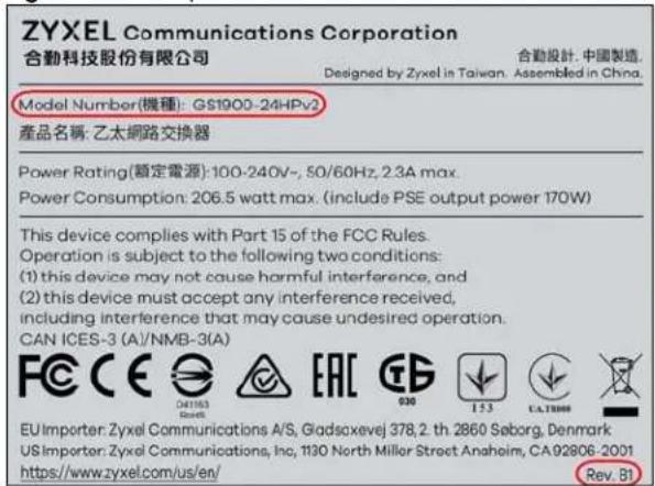
Note: The Rev. information is not shown on the back label of the A1 hardware version of GS1900 Series models.
- On the Web Configurator, see the Model Name and Revision fields in the Status screen.
Figure 2 Example Status > Device Information Screen: Model Name and Revision
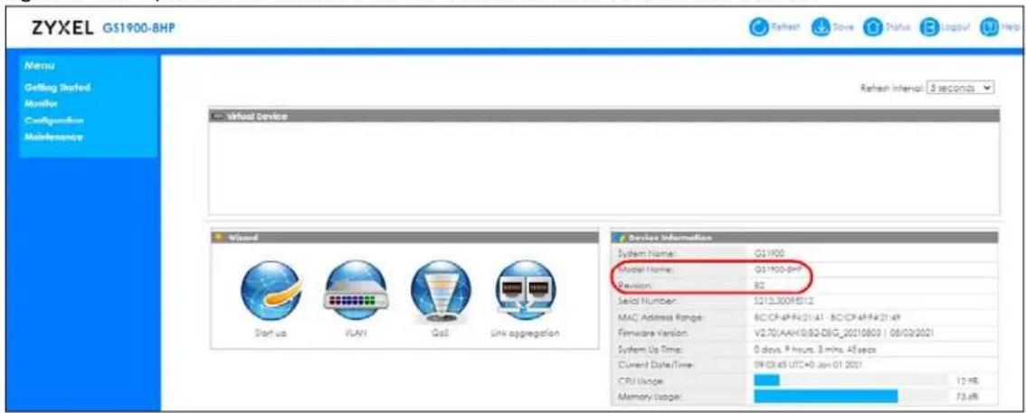
See the following table to use the back label or the Web Configurator to know the hardware version of your Switch.
Table 1 GS1900 Series Hardware Version Table
| MODEL BACK LABEL (Rev.) | WEB CONFIGURATOR(Model Name + Revision = HARDWARE VERSION) | |
| GS1900-8 None GS | 1900-8 A1 | |
| B1 GS1900-8 B1 | ||
| GS1900-8HP None | GS1900-8HP A1 | |
| B1 GS1900-8HP B1 | ||
| B2 GS1900-8HP B2 | ||
| GS1900-10HP None | GS1900-10HP A1 | |
| B1 GS1900-10HP B1 | ||
| GS1900-16 None GS | GS1900-16 A1 | |
| B1 GS1900-16 B1 | ||
| GS1900-24E None GS | GS1900-24E A1 | |
| B1 GS1900-24E B1 | ||
| GS1900-24EP None GS | GS1900-24EP A1 | |
| GS1900-24 None GS | GS1900-24 A1 | |
| B1 GS1900-24 B1 | ||
| GS1900-24HP None GS | GS1900-24HP A1 | |
| GS1900-24HPv2 B1 | GS1900-24HP B1 | |
| GS1900-48 None GS | GS1900-48 A1 | |
| B1 GS1900-48 B1 | ||
| GS1900-48HP None GS | GS1900-48HP A1 | |
| GS1900-48HPv2 B1 | GS1900-48HP B1 | |
1.1.2 Hardware Comparison
This User's Guide covers the following models. See Table 1 on page 18 for hardware version information.
Table 2 GS1900 Series Hardware Comparison Table 1
| MODEL GS1900-8 GS1900-8HP | GS1900-10HP GS1900-16 | ||||||||
| HARDWARE VERSION | A1 | B1 | A1 | B1 | B2 | A1 | B1 | A1 | B1 |
| 100/1000 Mbps Port | 8 | N | o | ||||||
| 100/1000 Mbps PoE Port | No | 8 | 8 | No | |||||
| 1G SFP Slots Fiber-optic | No | No | 2 | No | |||||
| Desktop | Yes | Yes | Yes | Yes | |||||
| Wall-mount | Yes | Yes | Yes | Yes | |||||
| Rack-mount | No | No | No | Yes | |||||
| Power ON/OFF Switch | Yes | No | Yes | No | Yes | No | No | ||
| Reboot Function | No | No | No | No | |||||
| Reset to Factory Default Function | Yes* | Yes** | Yes* | Yes** | Yes* | Yes** | Yes* | Yes** | |
| Note: * Press the RESET button for more than 6 seconds. ** Press the RESTORE button for more than 6 seconds. | |||||||||
| PoE MODE Button | No | No | No | No | |||||
| Kensington Lock | No | No | No | No | |||||
| Power | DC Jack-type | DC Pin-type | DC Jack-type | DC Pin-type | DC Jack-type | AC Input | |||
N O
Table 3 GS1900 Series Hardware Comparison Table 2
| MODEL | GS1900-24E | GS1900-24EP | GS1900-24 | GS1900-24HP | GS1900-48 | GS1900-48HP | |||||
| HARDWARE VERSION | A1 | B1 | A1 | A1 | B1 | A1 | B1 | A1 | B1 | A1 | B1 |
| 100/1000 Mbps Port | 24 | 12 | 24 | No | 48 | 24 | |||||
| 100/1000 Mbps PoE Port | No | 12 | No | 24 | No | 24 | |||||
| 1G SFP Slots Fiber-optic | No | No | 2 | 2 | 2 | 2 | |||||
| Desktop | Yes | No | No | No | No | No | |||||
| Wall-mount | Yes | No | No | No | No | No | |||||
| Rack-mount | Yes | Yes | Yes | Yes | Yes | Yes | |||||
| Power ON/OFF Switch | No | No | No | No | No | No | |||||
| Reboot Function No Yes* No Yes* No Yes* No Yes* | |||||||||||
| Note: * Press the RESET button. | |||||||||||
| Reset to Factory Default Function | Yes* | Yes** | Yes** | Yes* | Yes** | Yes* | Yes** | Yes* | Yes** | Yes* | Yes** |
| Note: * Press the RESET button for more than 6 seconds. ** Press the RESTORE button for more than 6 seconds. | |||||||||||
| PoE MODE Button | No | No | No | No | No | Yes | |||||
| Kensington Lock | No | Yes | No | Yes | No | Yes | No | Yes | No | Yes | |
| Power | AC Input | AC Input | AC Input | AC Input | AC Input | AC Input | |||||
1.2 Example Applications
This section shows a few examples of using the Switch in various network environments. Note that the Switch in the figure is just an example Switch and not your actual Switch.
1.2.1 PoE Example Application
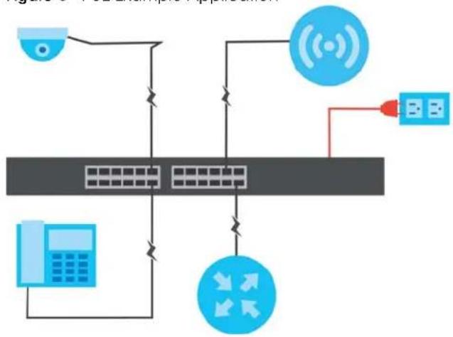
The Switch can supply PoE (Power over Ethernet) to Powered Devices (PDs) such as an IP camera, a wireless router, an IP telephone and a general outdoor router that are not within reach of a power outlet.
Figure 3 PoE Example Application
flowchart
graph TD
    A["Camera"] --> B["Network Device"]
    B --> C["Server"]
    C --> D["Data Input"]
    D --> E["Signal Receiver"]
    E --> F["Data Bus"]
    F --> G["Data Transfer"]
    G --> H["Server"]
    H --> I["Data Input"]
    I --> J["Data Transfer"]
    J --> K["Server"]
    K --> L["Data Input"]
    L --> M["Data Transfer"]
    M --> N["Server"]
    N --> O["Data Input"]
    O --> P["Data Transfer"]
    P --> Q["Server"]
    Q --> R["Data Input"]
    R --> S["Data Transfer"]
    S --> T["Server"]
    T --> U["Data Input"]
    U --> V["Data Transfer"]
    V --> W["Server"]
    W --> X["Data Input"]
    X --> Y["Data Transfer"]
    Y --> Z["Server"]
1.2.2 Backbone Example Application
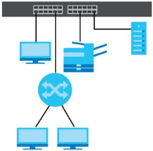
The Switch is an ideal solution for small networks where rapid growth can be expected in the near future. The Switch can be used standalone for a group of heavy traffic users. You can connect computers and servers directly to the Switch's port or connect other switches to the Switch.
All computers can share high-speed applications on the server. To expand the network, simply add more networking devices such as switches, routers, computers, print servers, and so on.
Figure 4 Backbone Example Application
flowchart
graph TD
    A["Server Rack"] --> B["Client 1"]
    A --> C["Client 2"]
    A --> D["Client 3"]
    A --> E["Client 4"]
    B --> F["Central System"]
    C --> F
    D --> F
    E --> F
    F --> G["Computer 1"]
    F --> H["Computer 2"]
1.2.3 Bridging or Fiber-optic Uplink Example Application
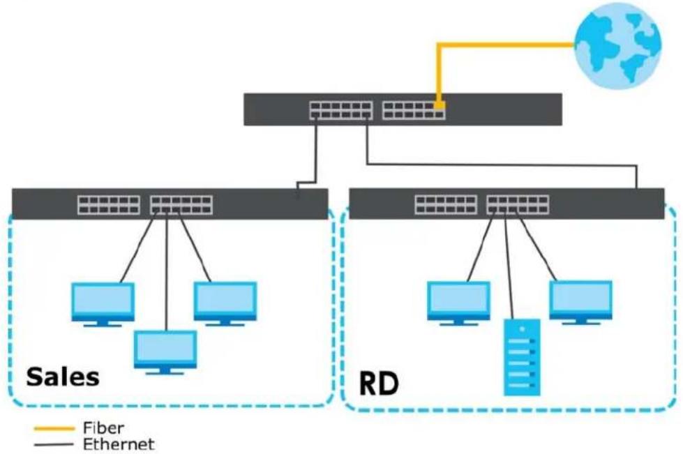
The Switch connects different company departments (RD and Sales) to the corporate backbone. It can alleviate bandwidth contention and eliminate server and network bottlenecks. All users that need high bandwidth can connect to high-speed department servers through the Switch. You can provide a super-fast uplink connection by using a Gigabit Ethernet or SFP port on the Switch.
Figure 5 Bridging or Fiber-optic Uplink Example Application
flowchart
graph TD
    A["Data Bus"] --> B["Sales"]
    A --> C["RD"]
    B --> D["Computer 1"]
    B --> E["Computer 2"]
    B --> F["Computer 3"]
    C --> G["Computer 4"]
    C --> H["Computer 5"]
    C --> I["Computer 6"]
    J["Fiber"] --> K["Ethernet"]
    K --> L["Global Network"]
1.2.4 Gigabit Ethernet to the Desktop
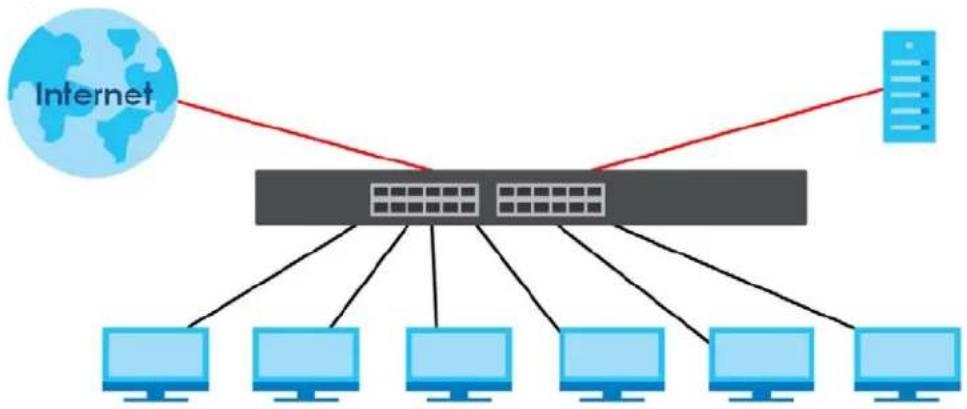
The Switch is an ideal solution for small networks which demand high bandwidth for a group of heavy traffic users. You can connect computers and servers directly to the Switch's port or connect other switches to the Switch.
In this example, all computers can share high-speed applications on the server and access the Internet. To expand the network, simply add more networking devices such as switches, routers, computers, print servers and so on.
Figure 6 Gigabit to the Desktop
flowchart
graph TD
    A["Internet"] --> B["Server"]
    B --> C["Computer 1"]
    B --> D["Computer 2"]
    B --> E["Computer 3"]
    B --> F["Computer 4"]
    B --> G["Computer 5"]
    B --> H["Computer 6"]
    B --> I["Computer 7"]
    B --> J["Computer 8"]
1.2.5 IEEE 802.1Q VLAN Application Example
A VLAN (Virtual Local Area Network) allows a physical network to be partitioned into multiple logical networks. Stations on a logical network belong to one or more groups. With VLAN, a station cannot
directly talk to or hear from stations that are not in the same groups unless such traffic first goes through a router.
For more information on VLANs, refer to Chapter 9 on page 86.
1.2.5.1 Tag-based VLAN Example
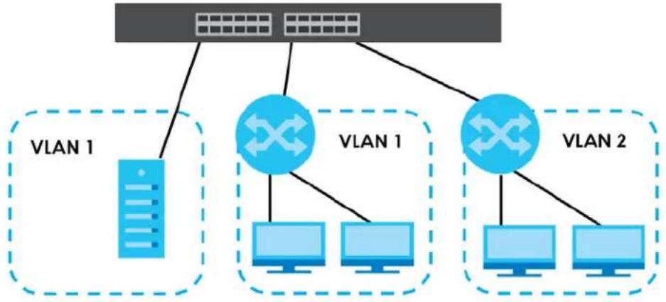
Ports in the same VLAN group share the same frame broadcast domain, therefore increasing network performance by reducing broadcast traffic. VLAN groups can be modified at any time by adding, moving or changing ports without any re-cabling.
Shared resources such as a server can be used by all ports in the same VLAN as the server. In the following figure only ports that need access to the server need to be part of VLAN 1. Ports can belong to other VLAN groups too.
Figure 7 Shared Server Using VLAN Example
flowchart
graph TD
    A["Central Server"] --> B["VLAN 1"]
    A --> C["VLAN 1"]
    A --> D["VLAN 2"]
    B --> E["Client 1"]
    C --> F["Client 1"]
    D --> G["Client 1"]
    E --> H["Computer 1"]
    F --> I["Computer 1"]
    G --> J["Computer 1"]
1.2.6 IPv6 Support
IPv6 (Internet Protocol version 6), is designed to enhance IP address size and features. The increase in IPv6 address size to 128 bits (from the 32-bit IPv4 address) allows up to 3.4 × 10^38 IP addresses. At the time of writing, the Switch supports the following features.
• Static address assignment and stateless auto-configuration
- Neighbor Discovery Protocol (a protocol used to discover other IPv6 devices in a network)
- Remote Management using PING, telnet, SNMP, HTTP and TFTP services
- ICMPv6 to report errors encountered in packet processing and perform diagnostic functions, such as "PING"
- IPv4/IPv6 dual stack; the Switch can run IPv4 and IPv6 at the same time
- DHCPv6 client
1.3 Ways to Manage the Switch
Use any of the following methods to manage the Switch.
- Web Configurator. This is recommended for everyday management of the Switch using a (supported) web browser. See Chapter 5 on page 50.
- TFTP. Use Trivial File Transfer Protocol for firmware upgrades and configuration backup or restore. See Section 33.1 on page 238, Section 33.3 on page 241, and Section 33.4 on page 242.
- SNMP. The device can be configured by a SNMP manager. See Section 32.3 on page 224.
- ZON Utility. ZON Utility is a program designed to help you deploy and perform initial setup on a network more efficiently. See Section 4.1 on page 45.
1.4 Good Habits for Managing the Switch
Do the following things regularly to make the Switch more secure and to manage the Switch more effectively.
- Change the password. Use a password that is not easy to guess and that consists of different types of characters, such as numbers and letters.
- Write down the password and put it in a safe place.
- Back up the configuration (and make sure you know how to restore it). Restoring an earlier working configuration may be useful if the device becomes unstable or even crashes. If you forget your password, you will have to reset the Switch to its factory default settings. If you backed up an earlier configuration file, you would not have to totally re-configure the Switch. You could simply restore your last configuration.
CHAPTER 2
Hardware Installation and
Connection
This chapter shows you how to install and connect the Switch.
2.1 Safety Precautions
Please observe the following before using the Switch:
- It is recommended to ask an authorized technician to attach the Switch on a desk or to the rack or wall. Use the proper screws to prevent damage to the Switch. See the Installation Requirements sections in this chapter to know the types of screws and screwdrivers for each mounting method.
- Make sure there is at least 2cm of clearance on the top and bottom of the Switch, and at least 5cm of clearance on all four sides of the Switch. This allows air circulation for cooling.
- Do NOT block the ventilation holes nor store cables or power cords on the Switch. Allow clearance for the ventilation holes to prevent your Switch from overheating. This is especially crucial when your Switch does not have fans. Overheating could affect the performance of your Switch, or even damage it.
- The surface of the Switch could be hot when it is functioning. Do NOT put your hands on it. You may get burned. This could happen especially when you are using a fanless Switch.
- The Switches with fans are not suitable for use in locations where children are likely to be present.
To start using the Switch, simply connect the power cables to turn it on.
2.2 Installation Scenarios
This chapter shows you how to install and connect the Switch.
The Switch can be:
- Placed on a desktop.
- Mounted on a wall.
- Rack-mounted on a standard EIA rack.
Note: Ask an authorized technician to attach the Switch to the rack or wall. See the Installation Requirements sections in this chapter to know the types of screws and screwdrivers for wall-mounting.
WARNING! Failure to use the proper screws may damage the unit.
Make sure you connect the Switch's power cord to a socket-outlet with an earthing connection or its equivalent.
WARNING! This Switch is not suitable for use in locations where children are likely to be present.
See Table 2 on page 19 for the comparison table of the hardware installation methods for each model.
2.3 Desktop Installation Procedure
1 Make sure the Switch is clean and dry.
2 Set the Switch on a smooth, level surface strong enough to support the weight of the Switch and the connected cables. Make sure there is a power outlet nearby.
3 Make sure there is at least 40 mm of clearance from the bottom to the Switch, and make sure there is enough clearance around the Switch to allow air circulation and the attachment of cables and the power cord. This is especially important for enclosed rack installations.
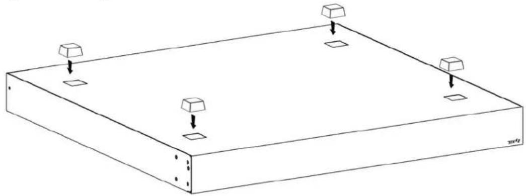
4 Remove the adhesive backing from the rubber feet.
5 Attach the rubber feet to each corner on the bottom of the Switch. These rubber feet help protect the Switch from shock or vibration and ensure space between devices when stacking.
Figure 8 Attaching Rubber Feet
natural_image
Isometric line drawing of a rectangular plate with four square supports and three downward arrows indicating downward force or displacement (no text or symbols)Note: Do NOT block the ventilation holes. Leave space between devices when stacking.
Note: For proper ventilation, allow at least 4 inches (10 cm) of clearance at the front and 3.4 inches (8 cm) at the back of the Switch. This is especially important for enclosed rack installations.
2.4 Wall Mounting
You may need screw anchors if mounting on a concrete or brick wall.
2.4.1 Wall-mounted Installation Requirement
The following are the wall-mounted installation requirements:
- Use screws with 6 mm – 8 mm (0.24" – 0.31") wide heads.
• See the following table for how far apart to place the screws.
Table 4 Distance between the centers of the holes for wall mounting
| GS1900-8 GS1 | 900-8HP GS1900-10HP GS1900-16 GS1900-24E | |
| 176 mm 176 | mm 176 mm 148 mm 207 mm |
The following figure shows the screw specifications used for wall mounting.
• D = 7.00 mm
• H = 2.00 mm
• L= 15.50 mm
- d = 3.50 mm
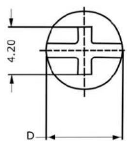
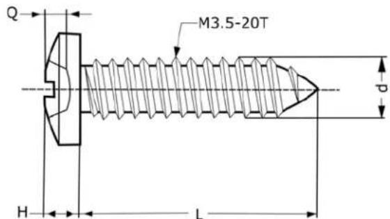
Do the following to attach your Switch to a wall.
1 Select a position free of obstructions on a wall strong enough to hold the weight of the Switch.
2 Mark two holes on the wall at the appropriate distance apart for the screws.
WARNING! Be careful to avoid damaging pipes or cables located inside the wall when drilling holes for the screws.
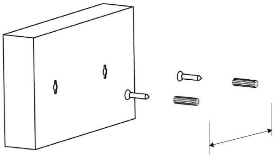
3 If using screw anchors, drill two holes for the screw anchors into the wall. Push the anchors into the full depth of the holes, then insert the screws into the anchors. Do NOT insert the screws all the way in – leave a small gap. The gap must be big enough for the screw heads to slide into the screw slots and the connection cables to run down the back of the Switch.
If not using screw anchors, use a screwdriver to insert the screws into the wall. Do NOT insert the screws all the way in - leave a gap.
natural_image
Diagram showing a rectangular block with three small holes and three separate screw-like objects aligned vertically (no text or symbols)Note: Make sure the screws are fastened well enough to hold the weight of the Switch with the connection cables.
4 Align the holes on the back of the Switch with the screws on the wall. Hang the Switch on the screws.
Note: Make sure there is enough clearance between the wall and the Switch to allow ventilation.
The Switch should be wall-mounted horizontally. The Switch's side panels with ventilation slots should not be facing up or down as this position is less safe.
2.5 Rack Mounting
The Switch can be mounted on an EIA standard size, 19-inch rack or in a wiring closet with other equipment. Follow the steps below to mount your Switch on a standard EIA rack using a rack-mounting kit.
Note: Make sure there is enough clearance between each equipment on the rack for air circulation.
2.5.1 Rack-mounted Installation Requirement
The following are the rack-mounted installation requirements:
- Two mounting brackets.
- Eight M3 flat head screws and a #2 Philips screwdriver.
- Four M5 flat head screws and a #2 Philips screwdriver.
Failure to use the proper screws may damage the unit.
2.5.1.1 Precautions
- Make sure the rack will safely support the combined weight of all the equipment it contains.
- Make sure the position of the Switch does not make the rack unstable or top-heavy. Take all necessary precautions to anchor the rack securely before installing the unit.
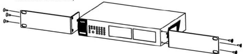
2.5.2 Attaching the Mounting Brackets to the Switch
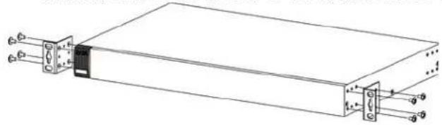
1 Position a mounting bracket on one side of the Switch, lining up the four screw holes on the bracket with the screw holes on the side of the Switch. See Table 1 on page 18 for hardware version information.
Figure 9 Attaching the Mounting Brackets (GS1900-16 A1/GS1900-16 B1, GS1900-24E A1/GS1900-24E B1, and GS1900-24EP A1)
natural_image
Line drawing of an electronic device with ports and a central panel (no text or symbols)Figure 10 Attaching the Mounting Brackets (GS1900-24 A1/GS1900-24 B1, GS1900-24HP A1/GS1900-24HP B1, GS1900-48 A1/GS1900-48 B1, and GS1900-48HP A1/GS1900-48HP B1)
natural_image
Technical line drawing of a rectangular electronic device with ports and connectors (no text or symbols)2 Using a #2 Philips screwdriver, install the M3 flat head screws through the mounting bracket holes into the Switch.
3 Repeat steps 1 and 2 to install the second mounting bracket on the other side of the Switch.
4 You may now mount the Switch on a rack. Proceed to the next section.
2.5.3 Mounting the Switch on a Rack
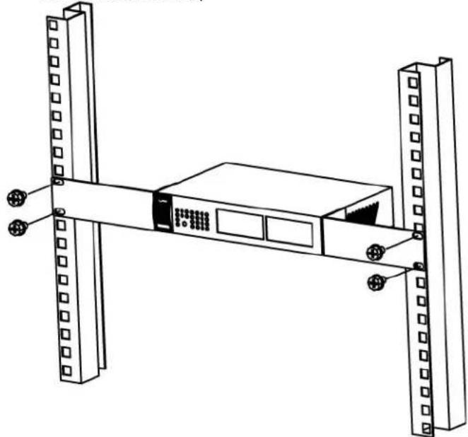
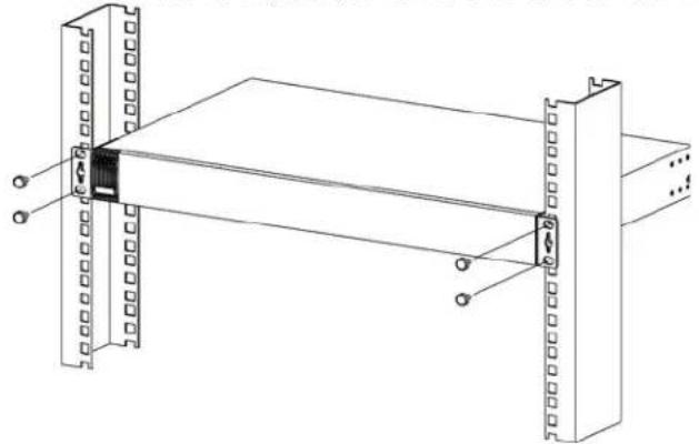
1 Position a mounting bracket (that is already attached to the Switch) on one side of the rack, lining up the two screw holes on the bracket with the screw holes on the side of the rack. See Table 1 on page 18 for hardware version information.
Figure 11 Mounting the Switch on a Rack (GS1900-16 A1/GS1900-16 B1, GS1900-24E A1/GS1900-24E B1, and GS1900-24EP A1)
natural_image
Technical line drawing of a server rack with two vertical supports and a central control unit (no text or symbols)Figure 12 Mounting the Switch on a Rack (GS1900-24 A1/GS1900-24 B1, GS1900-24HP A1/GS1900-24HP B1, GS1900-48 A1/GS1900-48 B1, and GS1900-48HP A1/GS1900-48HP B1)
natural_image
Technical line drawing of a mechanical assembly with two vertical plates and a central rod (no text or symbols)2 Using a #2 Philips screwdriver, install the M5 flat head screws through the mounting bracket holes into the rack.
Note: Make sure you tighten all the four screws to prevent the Switch from getting slanted.
3 Repeat steps 1 and 2 to attach the second mounting bracket on the other side of the rack.
CHAPTER 3
Hardware Overview
This chapter describes the front panel and rear panel of the Switch and shows you how to make the hardware connections.
3.1 Front Panel Connections
The following figures show the front panels of the Switch. See Table 1 on page 18 for hardware version information.
Figure 13 Front Panel: GS1900-8 A1

Figure 14 Front Panel: GS1900-8 B1

Figure 15 Front Panel: GS1900-8HP


Figure 16 Front Panel: GS1900-8HP B2

Figure 17 Front Panel: GS1900-10HP A1

Figure 18 Front Panel: GS1900-10HP B1

Figure 19 Front Panel: GS1900-16 A1

Figure 20 Front Panel: GS1900-16 B1
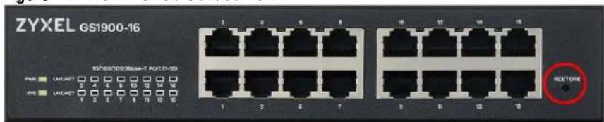
Figure 21 Front Panel: GS1900-24E A1

Figure 22 Front Panel: GS1900-24E B1

Figure 23 Front Panel: GS1900-24EP A1

Figure 24 Front Panel: GS1900-24 A1

Figure 25 Front Panel: GS1900-24 B1

Figure 26 Front Panel: GS1900-24HP A1

Figure 27 Front Panel: GS1900-24HP B1

natural_image
Front view of a network switchgear rack with multiple ports and indicator lights (no readable text or symbols)Figure 28 Front Panel: GS1900-48 A1

natural_image
Front view of a network switch device with multiple Ethernet ports and indicator lights (no readable text or symbols)Figure 29 Front Panel: GS1900-48 B1

Figure 30 Front Panel: GS1900-48HP A1

natural_image
Front view of a network switchgear rack with multiple ports and indicator lights (no readable text or symbols)Figure 31 Front Panel: GS1900-48HP B1

3.1.1 Ethernet Ports
The Switch has 1000Base-T auto-negotiating, auto-crossover Ethernet ports. In 10/100/1000 Mbps Gigabit Ethernet, the speed can be 10Mbps, 100 Mbps or 1000 Mbps. The duplex mode can be both half or full duplex at 100 Mbps and full duplex only at 1000 Mbps.
An auto-negotiating port can detect and adjust to the optimum Ethernet speed (10/100/1000 Mbps) and duplex mode (full duplex or half duplex) of the connected device.
An auto-crossover (auto-MDI/MDI-X) port automatically works with a straight-through or crossover Ethernet cable.
3.1.1.1 Default Ethernet Settings
The factory default negotiation settings for the Ethernet ports on the Switch are:
- Speed: Auto
- Duplex: Auto
- Flow control: Off
3.1.2 SFP Slots
These are slots for Small Form-Factor Pluggable (SFP) transceivers. A transceiver is a single unit that houses a transmitter and a receiver. Use a transceiver to connect a fiber-optic cable to the Switch. The Switch does not come with transceivers. You must use transceivers that comply with the Small Form-Factor Pluggable (SFP) Transceiver MultiSource Agreement (MSA). See the SFF committee's INF-8074i specification Rev 1.0 for details.
You can change transceivers while the Switch is operating. You can use different transceivers to connect to Ethernet switches with different types of fiber-optic connectors.
• Type: SFP connection interface
- Connection speed: 1 Gigabit per second (Gbps)
WARNING! To avoid possible eye injury, do not look into an operating fiber-optic module's connectors.
HANDLING! All transceivers are static sensitive. To prevent damage from electrostatic discharge (ESD), it is recommended you attach an ESD preventive wrist strap to your wrist and to a bare metal surface when you install or remove a transceiver.
STORAGE! All modules are dust sensitive. When not in use, always keep the dust plug on. Avoid getting dust and other contaminant into the optical bores, as the optics do not work correctly when obstructed with dust.
3.1.2.1 Transceiver Installation
Use the following steps to install a transceiver.
1 Attach an ESD preventive wrist strap to your wrist and to a bare metal surface.
2 Align the transceiver in front of the slot opening.
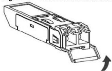
3 Make sure the latch is in the lock position (latch styles vary), then insert the transceiver into the slot with the exposed section of PCB board facing down.
4 Press the transceiver firmly until it clicks into place.
5 The Switch automatically detects the installed transceiver. Check the LEDs to verify that it is functioning properly.
6 Remove the dust plugs from the transceiver and cables (dust plug styles vary).
7 Identify the signal transmission direction of the fiber-optic cables and the transceiver. Insert the fiber-optic cable into the transceiver.
Figure 32 Latch in the Lock Position
natural_image
Technical line drawing of a mechanical component with no visible text or symbolsFigure 33 Transceiver Installation Example
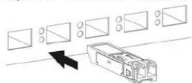
natural_image
Diagram showing a device with multiple rectangular components and an arrow pointing to it, no text or symbols present.Figure 34 Connecting the Fiber-optic Cables
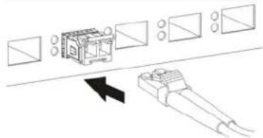
natural_image
Diagram showing a device with multiple rectangular components and a separate cylindrical component, no text or symbols present.3.1.2.2 Transceiver Removal
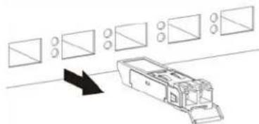
Use the following steps to remove an SFP transceiver.
1 Attach an ESD preventive wrist strap to your wrist and to a bare metal surface on the chassis.
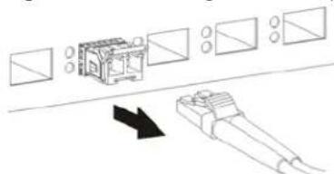
2 Remove the fiber-optic cables from the transceiver.
3 Pull out the latch and down to unlock the transceiver (latch styles vary).
Note: Make sure the transceiver's latch is pushed all the way down, so the transceiver can be pulled out successfully.
4 Pull the latch, or use your thumb and index finger to grasp the tabs on both sides of the transceiver, and carefully slide it out of the slot.
Note: Do NOT pull the transceiver out by force. You could damage it. If the transceiver will not slide out, grasp the tabs on both sides of the transceiver with a slight up or down motion and carefully slide it out of the slot. If unsuccessful, contact Zyxel Support to prevent damage to your Switch and transceiver.
5 Insert the dust plug into the ports on the transceiver and the cables.
Figure 35 Removing the Fiber-optic Cables
natural_image
Diagram showing a device with multiple rectangular components and a black arrow pointing to it, no text or symbols present.Figure 36 Opening the Transceiver's Latch Example

Figure 37 Transceiver Removal Example
natural_image
Diagram showing a vehicle with multiple rectangular components and a directional arrow, no text or symbols present.3.1.3 PoE Mode Button
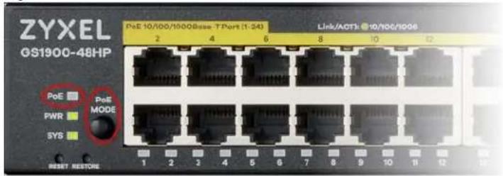
Push or release the PoE MODE button to change how the Ethernet port's Link/ ACT LED works.
- Each Ethernet port's LED is changed to act as a PoE MODE LED by pushing the PoE MODE button on the front panel. The PoE LED lights green when PoE mode is enabled.
- Each Ethernet port's LED is changed back to act as a Link/ ACT LED by releasing the PoE MODE button on the front panel. The PoE LED is off when PoE mode is disabled.
Figure 38 PoE LED and PoE MODE Button: GS1900-48HP A1
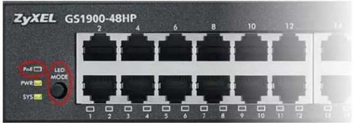
Figure 39 PoE LED and PoE MODE Button: GS1900-48HP B1
View the GS1900-48HP A1 / GS1900-48HP B1 LEDs to ensure proper functioning of the Switch and as an aid in troubleshooting (see Table 8 on page 42). See Table 1 on page 18 for hardware version information.
3.2 Rear Panel
The following figures show the rear panels of the Switch. See Table 1 on page 18 for hardware version information.
Figure 40 Rear Panel: GS1900-8 A1

Figure 41 Rear Panel: GS1900-8 B1

Figure 42 Rear Panel: GS1900-8HP
A1

natural_image
Close-up of a dark surface with a central circular connector labeled 'POWER SUVEC' and four corner markers (no additional text or symbols)B1

Figure 43 Rear Panel: GS1900-8HP B2

natural_image
Front view of a computer monitor with indicator lights and a power button labeled 'POWER DC 84V' (no additional text or symbols visible)Figure 44 Rear Panel: GS1900-10HP A1

Figure 45 Rear Panel: GS1900-10HP B1

Figure 46 Rear Panel: GS1900-16 A1
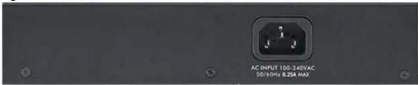
Figure 47 Rear Panel: GS1900-16 B1

Figure 48 Rear Panel: GS1900-24E A1

Figure 49 Rear Panel: GS1900-24E B1

Figure 50 Rear Panel: GS1900-24EP A1

Figure 51 Rear Panel: GS1900-24 A1

Figure 52 Rear Panel: GS1900-24 B1

Figure 53 Rear Panel: GS1900-24HP A1

Figure 54 Rear Panel: GS1900-24HP B1

Figure 55 Rear Panel: GS1900-48 A1

Figure 56 Rear Panel: GS1900-48 B1

Figure 57 Rear Panel: GS1900-48HP A1

Figure 58 Rear Panel: GS1900-48HP B1

3.2.1 Grounding
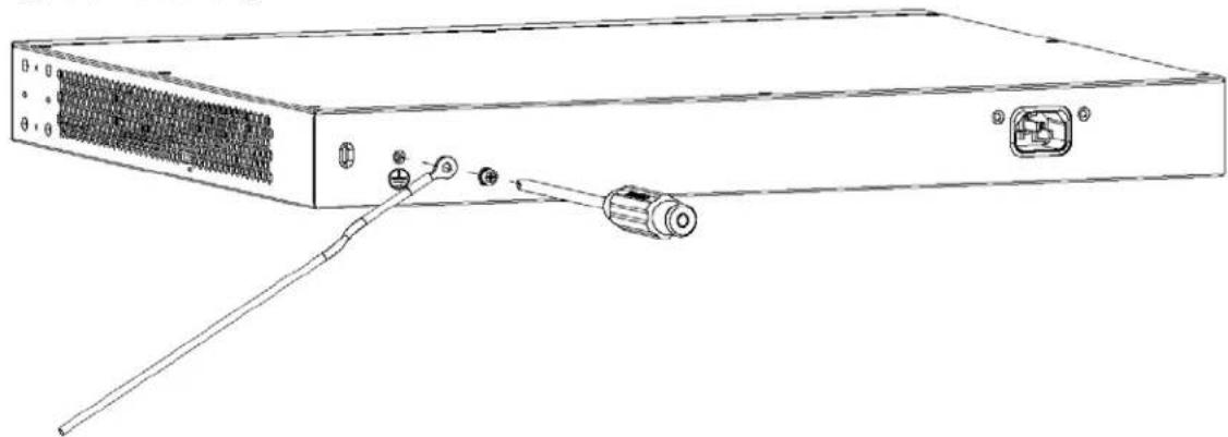
Grounding is a safety measure to direct excess electric charge to the ground. It prevents damage to the Switch, and protects you from electrocution. Use the grounding screw on the rear panel and the ground wire of the AC power supply to ground the Switch.
The grounding terminal and AC power ground where you install the Switch must follow your country's regulations. Qualified service personnel must ensure the building's protective earthing terminals are valid terminals.
Installation of Ethernet cables must be separate from AC power lines. To avoid electric surge and electromagnetic interference, use a different electrical conduit or raceway (tube/trough or enclosed conduit for protecting electric wiring) that is 15 cm apart, or as specified by your country's electrical regulations.
Any device that is located outdoors and connected to this product must be properly grounded and surge protected. To the extent permissible by your country's applicable law, failure to follow these guidelines could result in damage to your Switch which may not be covered by its warranty.
Note: The specification for surge or ESD protection assumes that the Switch is properly grounded.
1 Remove the M4 ground screw from the Switch's rear panel.
2 Secure a green or yellow ground cable (16 AWG or smaller) to the Switch's rear panel using the M4 ground screw.
Figure 59 Grounding
natural_image
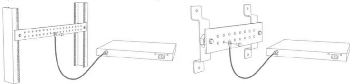
Line drawing of a server rack with ports and connectors (no text or symbols)3 Attach the other end of the ground cable to a grounding bar located on the rack where you install the Switch or to an on-site grounding terminal.
Figure 60 Attach Ground Cable to Grounding Bar or On-site Grounding Terminal
natural_image
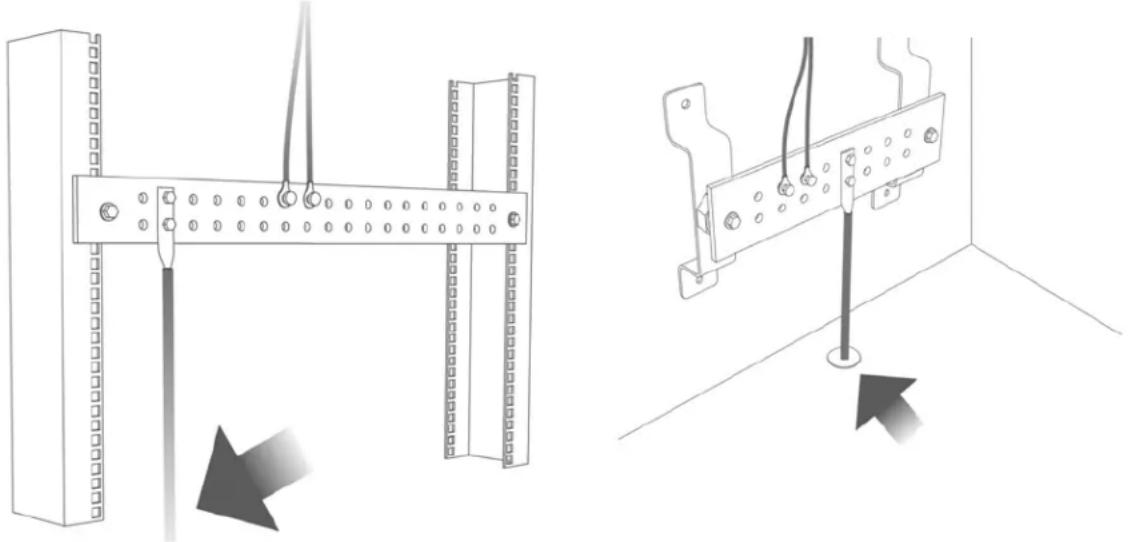
Technical line drawings of two electrical panel assemblies with wiring and mounting hardware (no text or symbols)4 The grounding terminal of the server rack or on-site grounding terminal must also be grounded and connected to the building's main grounding electrode. Make sure the grounding terminal is connected to the buildings grounding electrode and has an earth resistance of less than 10 ohms, or according to your country's electrical regulations.
Figure 61 Connecting to the Building's Main Grounding Electrode
natural_image
Technical illustration of two mechanical mounting brackets with wiring and a pull rod, shown from different angles (no text or symbols)If you are uncertain that suitable grounding is available, contact the appropriate electrical inspection authority or an electrician.
This device must be grounded. Do this before you make other connections.
3.2.2 Power Connection
Make sure you are using the correct power source and that no objects obstruct the airflow of the fans.
The Switch uses two power supply modules, one of which is redundant, so if one power module fails the system can operate on the remaining module.
Rear Panel Power Connection
Connect one end of the supplied power cord or power adapter to the power receptacle on the back of the Switch and the other end to the appropriate power source.
For Switches with a power switch (see Table 2 on page 19), use the POWER ON/OFF switch to have the Switch power on or off.
Connecting the Power
Use the following procedures to connect the Switch to a power source after you have installed it in a rack.
Note: Use the included power cord for the AC power connection.
1 Connect the female end of the power cord to the AC power socket.
2 Connect the other end of the cord to a power outlet.
Disconnecting the Power
The power input connectors can be disconnected from the power source individually.
1 Disconnect the power cord from the power outlet.
2 Disconnect the power cord from the AC power socket.
3.3 LEDs
After you connect the power to the Switch, view the LEDs to ensure proper functioning of the Switch and as an aid in troubleshooting. See Table 1 on page 18 for hardware version information.
Table 5 LED Descriptions
| LED COLOR STATUS DESCRIPTION | |||
| PWR Green On The system is turned on. | |||
| Off The system is off or has failed. | |||
| SYS Green On The system is on and functioning properly. | |||
| Blinking The system is rebooting and performing self-diagnostic tests. | |||
| Off The power is off or the system is not ready or malfunctioning. | |||
| Ethernet Ports | |||
| LNK/ACT | Green | Blinking | The system is transmitting/receiving to/from a 100/1000 Mbps Ethernet network. |
| On The link to a 100/1000 Mbps Ethernet network is up. | |||
| Off The link to an Ethernet network is down. | |||
| PoE(see Section 3.1.3 on page 36) | Green On | Power is supplied to all PoE Ethernet ports. | |
| Off There is no power supplied. | |||
| 1G SFP Slots (Fiber-optic Ports – see Section 1.1 on page 17) | |||
| LNK/ACT | Green | Blinking | The system is transmitting/receiving to/from a 100/1000 Mbps fiber-optic network. |
| On The link to a 100/1000 Mbps fiber-optic network is up. | |||
| Off The link to a fiber-optic network is down. | |||
Table 6 LED Descriptions (GS1900-8HP B1 and GS1900-10HP A1/GS1900-10HP B1 Only)
| LED COLOR STATUS DESCRIPTION | |||
| PWR Green On The system is turned on. | |||
| Off The system is off or has failed. | |||
| SYS Green On The system is on and functioning properly. | |||
| Blinking The system is rebooting. | |||
| Red On There is a system error. | |||
| PoE 10/100/1000Base-T Ports (1-8), 2 LEDs per portRightLeftLink 10M/100MLink 1000M | |||
| Right Amber On The port is in | PoE AF mode. That is, the Switch is following the IEEE 802.3af standard to supply power to this port. | ||
| Green On | The port is in | PoE AT mode. That is, the Switch is following the IEEE 802.3at standard to supply power to this port. | |
| Off Power is | not supplied to this port. | ||
| Left Amber On The link to a 10/100 Mbps Ethernet network is up. | |||
Table 7 LED Descriptions for SFP Port (GS1900-10HP A1/GS1900-10HP B1 Only)
| LED COLOR STATUS DESCRIPTION | |||
Two arrow LEDs for 1G SFP Slots (Fiber-optic Ports)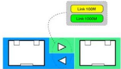 | |||
| right/left arrows Amber On The link to a 100 Mbps fiber-optic network is up. | |||
Table 8 LED Descriptions (GS1900-48HP A1/GS1900-48HP B1 Only)
| LED COLOR STATUS | US DESCRIPTION | ||
| Ethernet Ports when PoE MODE button is OFF | |||
| PoE(see Section3.1.3 on page 36) | Off | Each Ethernet port's LED acts as a Link/ACT LED. | |
| LED COLOR STATUS DESCRIPTION | |||
| LNK/ACT | Green | Blinking | The system is transmitting/receiving to/from a 100/1000 Mbps Ethernet network. |
| On The link to a 100/1000 Mbps Ethernet network is up. | |||
| Off The link to an Ethernet network is down. | |||
| Ethernet Ports when PoE MODE button is ON | |||
| PoE | Green | On | Each Ethernet port's LED acts as a PoE MODE LED. |
| PoE Mode Amber | On The port is in PoE AF | mode. That is, the Switch is following the IEEE 802.3af standard to supply power to this port. | |
| Green On | The port is in | PoE AT mode. That is, the Switch is following the IEEE 802.3at standard to supply power to this port. | |
| Off Power is | not supplied to this port. | ||
| 1G SFP Slots (Fiber-optic Ports – see Section 1.1 on page 17) | |||
| LNK/ACT | Green | Blinking | The system is transmitting/receiving to/from a 100/1000 Mbps fiber-optic network. |
| On The link to a 100/1000 Mbps fiber-optic network is up. | |||
| Off The link to a fiber-optic network is down. | |||
3.4 Resetting the Switch
If you lock yourself (and others) from the Switch, or you forget your password, or cannot access the Web Configurator, you will need to reload the factory-default configuration file.
- For the A1 hardware version, use the RESET button.
- For the B1 and later hardware version, use the RESTORE button.
To check which hardware version you are using, refer to Section 1.1.1 on page 17.
This means that you will lose all configurations that you had previously and the default Switch IP address, user name and password will be reset to 192.168.1.1, admin and 1234 respectively.
Follow the steps below to reset the Switch back to factory defaults.
1 Make sure the SYS LED is steady green (not blinking). Use a pointed instrument such as a pin to access the RESET/RESTORE buttons on the front of the Switch as shown in Section 3.1 on page 31.
2 Press the button for more than 6 seconds. After releasing the button, the SYS LED begins to blink. Wait for the Switch to restart (the SYS LED will be steady green again). This takes up to 2 minutes. See Section 3.3 on page 41 for more information about the LED behavior.
Note: If you want to access the Switch Web Configurator again, you may need to change the IP address of your computer to be in the same subnet as that of the default Switch IP address (192.168.1.1).
3.5 Rebooting the Switch
Use any of the following methods to reboot the Switch without turning the power off.
- RESET button. Refer to Table 2 on page 19 and Table 3 on page 19 to see the list of models that support the RESET button to reboot the Switch. See Section 3.3 on page 41 for more information about the LED behavior.
- Web Configurator. Click the Reboot button in the Maintenance >Reboot screen. See Section 33.8 on page 249 for more information.
- ZON Utility. Click the Reboot Device button in the ZON Utility screen. See Section 4.1.2 on page 46 for more information.
CHAPTER 4 ZON Utility
This chapter describes the screens for ZON Utility.
4.1 Zyxel One Network (ZON) Utility
ZON Utility is a program designed to help you deploy and manage a network more efficiently. It detects devices automatically and allows you to do basic settings on devices in the network without having to be near it.
The ZON Utility issues requests through Zyxel Discovery Protocol (ZDP) and in response to the query, the device responds back with basic information including IP address, firmware version, location, system and model name in the same broadcast domain. The information is then displayed in the ZON Utility screen and you can perform tasks like basic configuration of the devices and batch firmware upgrade in it. You can download the ZON Utility at www.zyxel.com and install it in a computer (Windows operating system).
4.1.1 Requirements
Before installing the ZON Utility on your computer, please make sure it meets the requirements listed below.
Operating System
At the time of writing, the ZON Utility is compatible with:
- Windows 7 (both 32-bit / 64-bit versions)
- Windows 8 (both 32-bit / 64-bit versions)
- Windows 8.1 (both 32-bit / 64-bit versions)
• Window 10 (both 32-bit / 64-bit versions)
Note: To check for your Windows operating system version, right-click on My Computer > Properties. You should see this information in the General tab.
Hardware
Here are the minimum hardware requirements to use the ZON Utility on your PC.
- Core i3 processor
• 2 G B R A M
• 100 MB free hard disk
• WXGA (Wide XGA 1280 by 800)
4.1.2 Run the ZON Utility
1 Double-click the ZON Utility to run it.
2 The first time you run the ZON Utility, you will see if your device and firmware version support the ZON Utility. Click the OK button to close this screen.
Figure 62 Supported Devices and Versions
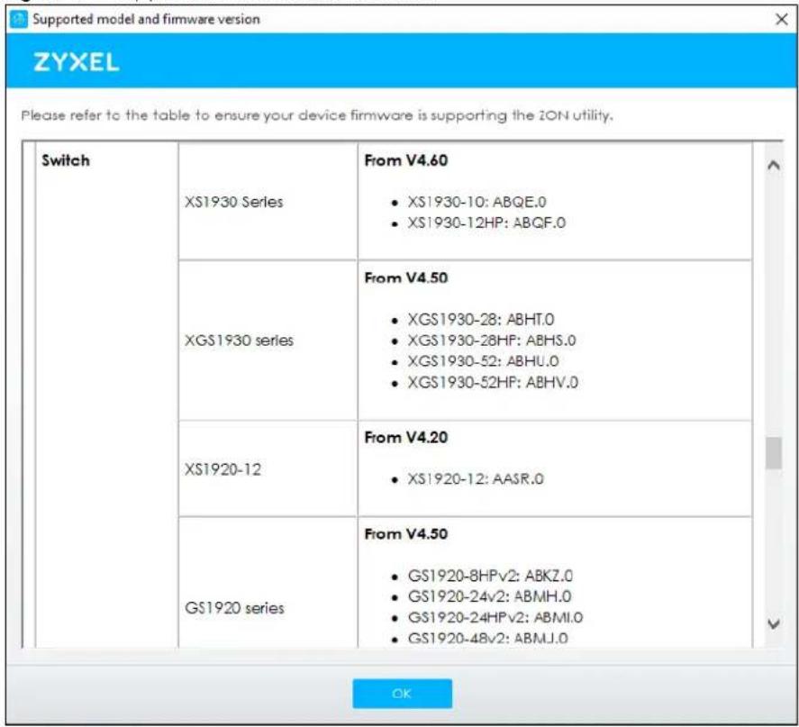
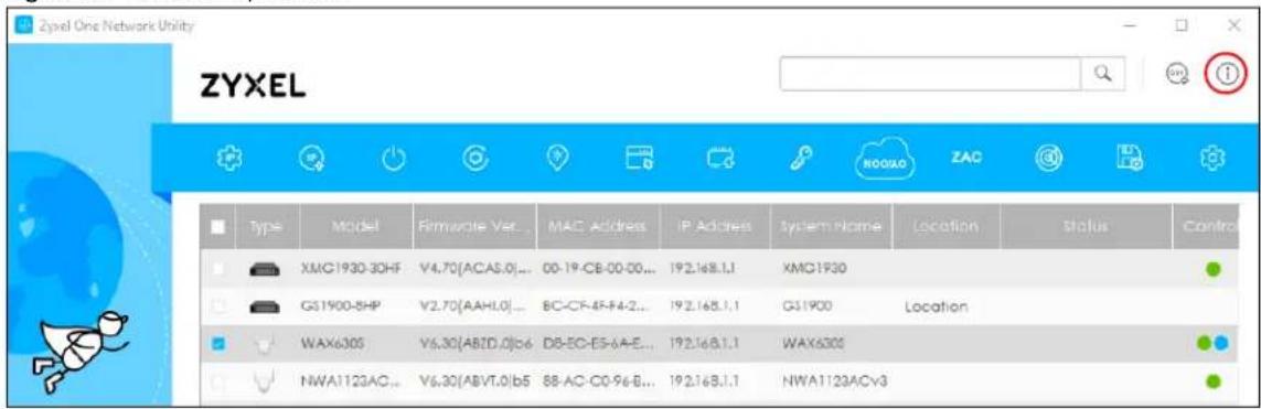
If you want to check the supported models and firmware versions later, you can click the Show information about ZON icon in the upper right hand corner of the screen. Then select the Supported model and firmware version link. If your device is not listed here, see the device release notes for ZON utility support. The release notes are in the firmware zip file on the Zyxel web site.
Figure 63 ZON Utility Screen
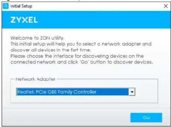
3 Select a network adapter to which your supported devices are connected.
Figure 64 Network Adapter
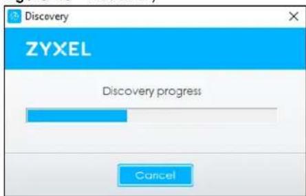
4 Click the Go button for the ZON Utility to discover all supported devices in your network.
Figure 65 Discovery
5 The ZON Utility screen shows the devices discovered.
Figure 66 ZON Utility Screen
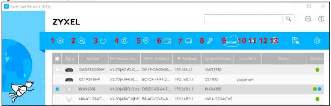
6 Select a device and then use the icons to perform actions. Some functions may not be available for your devices.
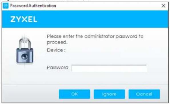
Note: You must know the selected device admin password before taking actions on the device using the ZON Utility icons.
Figure 67 Password Prompt
The following table describes the icons numbered from left to right in the ZON Utility screen.
Table 9 ZON Utility Icons
| ICON DESCRIPTION | |
| 1 IP configuration Change | the selected device's IP address. |
| 2 Renew IP Address Update | a DHCP-assigned dynamic IP address. |
| 3 Reboot Device | Use this icon to restart the selected devices. This may be useful when troubleshooting or upgrading new firmware. |
| 4 Reset Configuration to Default | If you forget your password or cannot access the Web Configurator, you can use this icon to reload the factory-default configuration file. This means that you will lose all configurations that you had previously. |
| 5 Locator LED | Use this icon to locate the selected device by causing its Locator LED to blink. |
| 6 Web GUI | Use this to access the selected device web configurator from your browser. You will need a user name and password to log in. |
| 7 Firmware Upgrade | Use this icon to upgrade new firmware to selected devices of the same model. Make sure you have downloaded the firmware from the Zyxel website to your computer and unzipped it in advance. |
| 8 Change Password | Use this icon to change the admin password of the selected device. You must know the current admin password before changing to a new one. |
| ICON | DESCRIPTION |
| 9 Configure NCC Discovery | You must have Internet access to use this feature. Use this icon to enable or disable the Nebula Control Center (NCC) discovery feature on the selected device. If it is enabled, the selected device will try to connect to the NCC. Once the selected device is connected to and has registered in the NCC, it will go into the Nebula cloud management mode. |
| 10 ZAC Use this icon to run the Zyxel AP Configurator of the selected AP. | |
| 11 Clear and Rescan | Use this icon to clear the list and discover all devices on the connected network again. |
| 12 Save Configuration | Use this icon to save configuration changes to permanent memory on a selected device. |
| 13 Settings | Use this icon to select a network adapter for the computer on which the ZON utility is installed, and the utility language. |
The following table describes the fields in the ZON Utility main screen.
Table 10 ZON Utility Fields
| LABEL DESCRIPTION | |
| Type This field displays an icon of the kind of device discovered. | |
| Model This field displays the model name of the discovered device. | |
| Firmware Version This field displays the firmware version of the discovered device. | |
| MAC Address This field displays the MAC address of the discovered device. | |
| IP Address | This field displays the IP address of an internal interface on the discovered device that first received an ZDP discovery request from the ZON Utility. |
| System Name This field displays the system name of the discovered device. | |
| Location This field displays where the discovered device is. | |
| Status This field displays whether changes to the discovered device have been done successfully. As the Switch does not support IP Configuration, Renew IP address and Flash Locator LED, this field displays “Update failed”, “Not support Renew IP address” and “Not support Flash Locator LED” respectively. | |
| NCC Discovery This field displays if the discovered device supports the Nebula Control Center (NCC) discovery feature. If it is enabled, the selected device will try to connect to the NCC. Once the selected device is connected to and has registered in the NCC, it will go into the Nebula cloud management mode. | |
| Serial Number | Enter the admin password of the discovered device to display its serial number. |
| Hardware Version | This field displays the hardware version of the discovered device. |
CHAPTER 5
Web Configurator
5.1 Overview
This section introduces the configuration and functions of the Web Configurator.
The Web Configurator is an HTML-based management interface that allows easy Switch setup and management through Internet browser. Use a browser that supports HTML5, such as Microsoft Edge, Internet Explorer 11, Mozilla Firefox, or Google Chrome. The recommended minimum screen resolution is 1024 by 768 pixels.
In order to use the Web Configurator, you need to allow:
• Web browser pop-up windows
- JavaScript (enabled by default)
- Java permissions (enabled by default)
5.2 Access
1 Make sure your Switch hardware is properly connected. See the Quick Start Guide.
2 Browse to https://192.168.1.1. The Login screen appears.
Figure 68 Login Screen
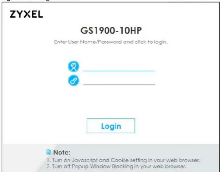
3 Enter the user name (default: "admin") and password (default: "1234").
4 Click Login. If you logged in using the default user name and password, getting start appears. The Getting Started screen appears every time you log in using the default user name and default password.
5 If you did not change the default administrator password and/or SNMP community values, a warning screen displays each time you log into the Web Configurator. Click Password / SNMP to open a screen where you can change the administrator and SNMP passwords simultaneously. Otherwise, click Ignore to close it.
Figure 69 Web Configurator: Warning
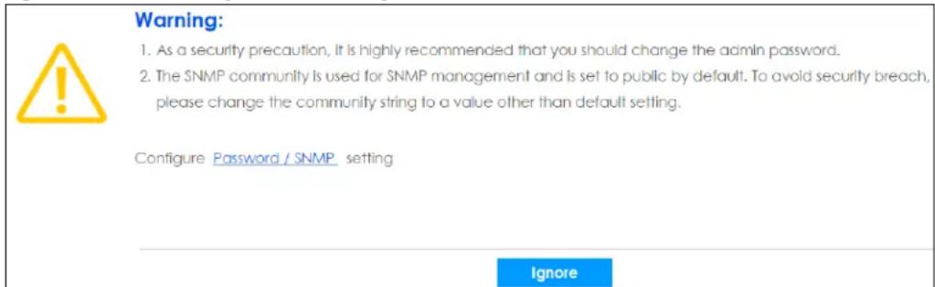
Figure 70 Web Configurator: Password

Change the default administrator and/or SNMP passwords, and then click Apply to save your changes.
Table 11 Web Configurator: Password > Users/SNMP
| LABEL DESCRIPTION | |
| UsersUse this section to set the admin login password. | |
| User | This is the default administrator account with the “admin” user name. You cannot change the default administrator user name. |
| Old Password | Type the existing system password (1234is the default password when shipped). |
| New Password | Enter your new system password using the keyboard characters ("a-z", "A-Z", "0-9", ~!@#$%^&*()_+`-={}[]::<>./). The allowed string length is 1 to 64. |
| New Password Confirm | Re-enter your new system password for confirmation. |
| Apply | Click Applyto save your changes to the Switch's run-time memory. The Switch loses these changes if it is turned off or loses power, so use the Savelink on the top navigation panel to save your changes to the non-volatile memory when you are done configuring. |
| Cancel | Click Cancelto begin configuring the password section afresh. |
| SNMPUse this section to specify the SNMP community and access right values. | |
| Community | Enter a string identifying the community name that this entry should belong to. The allowed string length is 1 to 20, and the allowed content is ASCII characters from 33 to 126. |
| Access Right | Select the access mode for this entry. The possible values are Read-Only and Read-Write. |
| Apply | Click Apply to save your changes to the Switch's run-time memory. The Switch loses these changes if it is turned off or loses power, so use the Save link on the top navigation panel to save your changes to the non-volatile memory when you are done configuring. |
| Cancel | Click Cancel to begin configuring this screen afresh. |
5.3 Navigating the Web Configurator
The following summarizes how to navigate the Web Configurator from the Getting Started screen. This guide uses the GS1900-10HP and GS1900-24HP screens as an example. The screens may vary slightly for different models.
Figure 71 Web Configurator's Main Screen
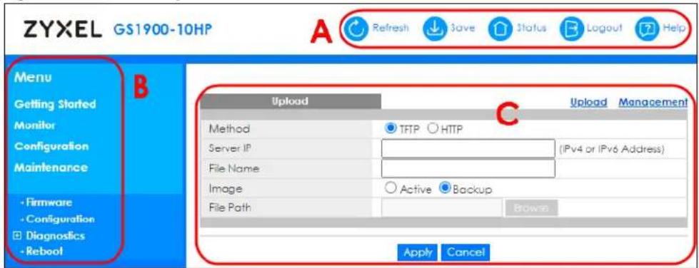
The Web Configurator's main screen is divided into these parts:
• A - Title Bar
• B – Navigation Panel
• C - Main Window
5.3.1 Title Bar
The title bar provides some useful links that always appear over the screens below, regardless of how deep into the Web Configurator you navigate.
Figure 72 Title Bar

The icons provide the following functions.
Table 12 Title Bar: Web Configurator Icons
| LABEL DESCRIPTION | |
| Refresh Click Refresh to reload the page. | |
| Save | Click this to apply your changes to the Switch's run-time memory. The Switch loses these changes if it is turned off or loses power, so use the Save link on the top navigation panel to save your changes to the non-volatile memory when you are done configuring. |
| Status Click this to display basic information about the Switch. | |
| Logout Click this to log out of the Web Configurator. | |
| Help Click this to open the help page for the current screen. | |
Click Logout in a screen to exit the Web Configurator. You have to log in with your password again after you log out. This is recommended after you finish a management session for security reasons.
5.3.2 Navigation Panel
Use the menu items on the navigation panel to open screens to configure Switch features. The following sections introduce the Switch's navigation panel menus and their screens.
Figure 73 Navigation Panel
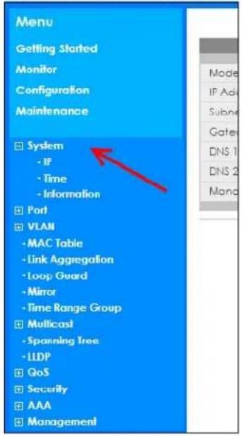
Getting Started
Getting Started displays general device information, system status, system resource usage, and interface status.
For details on Getting Started features, see Chapter 6 on page 61.
Monitor Menu
The monitor menu screens display status and statistics information.
Table 13 Monitor Menu Screens Summary
| FOLDER OR LINK TAB FUNCTION | ||
| System | This link takes you to a screen where you can see general identification information for the Switch. | |
| IP | IPv4 | This link takes you to a screen where you can see an IPv4 interface and the IPv4 settings on the Switch. |
| IPv6 | This link takes you to a screen where you can see an IPv6 interface and the IPv6 settings on the Switch. | |
| Information | This link takes you to a screen that displays general system information: system name, system location, and system contact. | |
| Port | This link takes you to screens where you can see speed, flow control and priority settings of individual Switch ports. | |
| Port | Status | This link takes you to a screen to view the statistics of individual Switch ports. |
| Port Counters | This link takes you to a screen to view the interface, port 1 interface mib counters, port 1 etherlike mib counters, port 1 RMON mib counters settings of individual Switch ports. | |
| Bandwidth Utilization | This link takes you to a screen to view the Tx and Rx bandwidth utilization of individual Switch ports. | |
| PoE | This link takes you to a screen to view the current amount of power that PDs are receiving from the Switch. | |
| Bandwidth Management | This link takes you to a screen to view the egress global burst and port rate for individual Switch ports. | |
| Storm Control | This link takes you to a screen that displays broadcast filters. | |
| VLAN | This link takes you to screens where you can see port-based or 802.1Q VLAN (depending on what you configured in the Switch Setup menu). You can also see a protocol based VLAN or a subnet based VLAN in these screens. | |
| VLAN | VLAN | This link takes you to a screen to view the Switch's VLAN settings. |
| Port | This link takes you to a screen to view the Switch's port setting in VLAN. | |
| VLAN Port | This link takes you to a screen to view the Switch's VLAN port settings. | |
| Guest VLAN | This link takes you to a screen to view the Switch's guest VLAN settings. | |
| Voice VLAN | This link takes you to a screen to view the Switch's global and port voice VLAN settings for voice traffic. | |
| MAC Table | This link takes you to a screen where you can view the MAC address and VLAN ID of a device attach to a port. You can also view what kind of MAC address it is. | |
| Link Aggregation | This link takes you to screen where you can view aggregate physical links to form one logical, higher-bandwidth link. | |
| Loop Guard | This link takes you to a screen where you can view protection against network loops that occur on the edge of your network. | |
| Multicast | This link takes you to screen where you can view various multicast features, IGMP snooping and create multicast VLANs. | |
| FOLDER OR LINK | TAB FUNCTION | |
| IGMP | VLAN | This link takes you to a screen to view the Switch's IGMP VLAN status. |
| Statistics | This link takes you to a screen to view the Switch's IGMP statistics. | |
| Group | This link takes you to a screen to view the Switch's IGMP group information. | |
| Router | This link takes you to a screen to view the Switch's IGMP router information. | |
| Spanning Tree This link takes you to screens where you can view CIST, MST, STP preventing network loops. | ||
| LLDP | This link takes you to screens where you can view the LLDP settings. | |
| Statistics | This link takes you to a screen to view the Switch's LLDP global and port statistics. | |
| Remote Information | This link takes you to a screen to view the Switch's LLDP remote device information. | |
| Overloading This link takes you to a screen to view the Switch's LLDP port overloading status. | ||
| Security | This link takes you to screens where you can view the port security and 802.1X settings. | |
| Port Security | This link takes you to a screen to view the Switch's port security status. | |
| 802.1X | Port | This link takes you to a screen to view the Switch's 802.1X port status. |
| Authenticated Hosts | This link takes you to a screen to view the Switch's 802.1X security authenticated host status. | |
| Management | This link takes you to screens where you can view the syslog and error disable status. | |
| Syslog | This link takes you to a screen to view the Switch's logging filter settings and system logs. | |
| Error Disable | This link takes you to a screen to view the Switch's global and port error disable status. | |
Configuration Menu
Use the configuration menu screens to configure the Switch's features.
Table 14 Configuration Menu Screens Summary
| FOLDER OR LINK | TAB FUNCTION | |
| System | This link takes you to a screen where you can configure general identification information and time settings for the Switch. | |
| IP | IPv4 | This link takes you to a screen where you can enable an IPv4 interface and configure the IPv4 settings on the Switch. |
| IPv6 This link takes you to a screen where you can enable an IPv6 interface and configure the IPv6 settings on the Switch. | ||
| Time | System Time | This link takes you to a screen to configure the time of the system. |
| SNTP Server | This link takes you to a screen to configure the SNTP server settings. | |
| Information This link takes you to a screen that configures general system information: system name, system location, and system contact. | ||
| Port This link takes you to screens where you can configure speed, flow control and priority settings for individual Switch ports. | ||
| Port This link takes you to a screen to view the Switch's port settings and select individual Switch ports for configuration. | ||
| EEE This link takes you to a screen to view the Switch's port EEE (Energy-Efficient Ethernet) state and select ports for configuration. | ||
| PoE | Global | This link takes you to a screen where you can configure the global settings for the Switch to supply power over Ethernet (PoE). |
| Port | This link takes you to a screen where you can configure port PoE settings. | |
| Bandwidth Management | This link takes you to a screen where you can view and configure the egress global burst and port rate. | |
| Storm Control This link takes you to a screen to set up broadcast filters. | ||
| VLAN | This link takes you to screens where you can configure VLAN, guest VLAN, and voice VLAN settings. | |
| VLAN | VLAN | This link takes you to a screen where you can view and add/edit the VLAN settings. |
| Port | This link takes you to a screen where you can view port settings and select VLANs for configuration. | |
| VLAN Port | This link takes you to a screen where you can view and configure the VLAN port settings. | |
| Guest VLAN | Global | This link takes you to a screen where you can configure the global guest VLAN settings. |
| Port | This link takes you to a screen where you can view the guest VLAN port settings and select VLAN ports for configuration. | |
| Voice VLAN | Global | This link takes you to a screen where you can configure the global voice VLAN settings. |
| OUI | This link takes you to a screen where you can view and edit/delete the OUI settings. | |
| Port | This link takes you to a screen where you can view the voice VLAN port settings and select a port for configuration. | |
| MAC Table | This link takes you to a screen where you can configure the MAC address and VLAN ID of a device attach to a port. You can also configure what kind of MAC address it is. | |
| Static MAC | This link takes you to screens where you can configure static MAC addresses for a port. These static MAC addresses do not age out. | |
| Filtering MAC | This link takes you to a screen to set up filtering rules. | |
| Dynamic Age | This link takes you to a screen where you can enter the dynamic MAC aging time. | |
| FOLDER OR LINK | TAB | FUNCTION |
| Link Aggregation This link | takes you to a screen where you can logically aggregate physical links to form one logical, higher-bandwidth link. | |
| Global | This link takes you to a screen where you can configure the global link aggregation settings. | |
| LAG Management | This link takes you to a screen where you can configure the LAG management settings. | |
| LAG Port This link | takes you to a screen where you can view or edit the LAG port settings. | |
| LACP Port | This link takes you to a screen where you can view or edit the LACP port settings. | |
| Loop Guard | This link takes you to screens where you can configure protection against network loops that occur on the edge of your network. | |
| Global | This link takes you to a screen where you can configure the global loop guard settings. | |
| Port | This link takes you to a screen where you can view or edit the port's loop guard settings. | |
| Mirror | This link takes you to a screen where you can copy traffic from one port or ports to another port. This allowing you to examine the traffic from the first port without interference. | |
| Time Range Group | This link takes you to a screen where you can view/define/delete time range (schedule) rules. | |
| Multicast This link takes you to a screen where you can configure various multicast features, IGMP snooping and create multicast VLANs. | ||
| IGMP | Global | This link takes you to a screen where you can configure the IGMP global settings. |
| VLAN | This link takes you to a screen where you can view or edit the IGMP VLAN settings. | |
| Router Port | This link takes you to a screen where you can add or view the router port settings. | |
| Profile | This link takes you to a screen where you can add or view the IGMP profile settings. | |
| Throttling | This link takes you to a screen where you can view or edit the throttling settings. | |
| Spanning Tree | This link takes you to screens where you can configure the RSTP/MRSTP/MSTP to prevent network loops. | |
| Global | This link takes you to a screen where you can configure the global settings. | |
| STP Port | This link takes you to a screen where you can view or edit the STP port settings. | |
| CIST | This link takes you to a screen where you can configure the CIST settings. | |
| CIST Port | This link takes you to a screen where you can view or edit the CIST port settings. | |
| MST | This link takes you to a screen where you can add/edit/delete the MST instance settings. | |
| MST Port | This link takes you to a screen where you can view or edit the MST port settings. | |
| LLDP | This link takes you to screens where you can configure the global, port, local information, MED network policy, and MED port settings. | |
| Global | This link takes you to a screen where you can configure the global LLDP settings. | |
| Port | This link takes you to a screen where you can view or edit the LLDP port settings. | |
| Local Information | This link takes you to a screen where you can view or edit the LLDP local information settings. | |
| MED Network Policy | This link takes you to a screen where you can add/edit/delete the LLDP MED network policy settings. | |
| MED Port | This link takes you to a screen where you can view or edit the LLDP MED port settings. | |
| QoS | This link takes you to screens where you can configure the general and trust mode settings. | |
| General | Port | This link takes you to a screen where you can view or edit the QoS port settings. |
| Queue | This link takes you to a screen where you can configure queuing with associated queue weights for each port. | |
| CoS Mapping | This link takes you to a screen where you can configure the CoS to queue mapping and Queue to CoS mapping settings. | |
| DSCP Mapping | This link takes you to a screen where you can configure the DSCP to queue and queue to DSCP mapping settings. | |
| IP Precedence Mapping | This link takes you to a screen where you can configure the IP precedence to queue and queue to IP precedence mapping settings. | |
| Trust Mode | Global | This link takes you to a screen where you can configure the global trust mode setting. |
| Port This link takes you to a screen where you can view or edit the QoS port trust mode setting. | ||
| Security | This link takes you to screens where you can configure the port security, port isolation, 802.1X and DoS settings. | |
| Port Security | Global | This link takes you to a screen where you can enable the global port security. |
| Port | This link takes you to a screen where you can view or edit the port's security settings. | |
| Port Isolation | This link takes you to a screen where you can view the state or enable/ disable port isolation. | |
| 802.1X | Global | This link takes you to a screen where you can enable the global 802.1X security setting. |
| Port | This link takes you to a screen where you can view or edit the 802.1X port security settings. | |
| DoS | Global | This link takes you to a screen where you can enable Denial of Service (DoS). |
| Port | This link takes you to a screen where you can view or edit the Switch's port DoS state. | |
| AAA | This link takes you to a screen where you can view authentication, authorization and accounting services through external servers. The external servers can be either RADIUS (Remote Authentication Dial-In User Service) or TACACS+ (Terminal Access Controller Access-Control System Plus). | |
| Auth Method | This link takes you to a screen where you can add/edit/delete an authentication method. | |
| RADIUS | This link takes you to a screen where you can add/edit/delete RADIUS server settings. | |
| TACACS+ | This link takes you to a screen where you can add/edit/delete TACACS+ server settings. | |
| Management This link takes you to screens where you can configure the syslog, SNMP, error disable, HTTP/HTTPS, users and remote access control. | ||
| Syslog | Global | This link takes you to a screen where you can enable syslog (system logging). |
| Local | This link takes you to a screen where you can add/edit/delete the local syslog settings. | |
| Remote | This link takes you to a screen where you can add/edit/delete the remote syslog settings. | |
| SNMP | Global | This link takes you to a screen where you can enable SNMP (Simple Network Management Protocol). |
| Community This link takes you to a screen where you can add/delete the SNMP community settings. | ||
| Group | This link takes you to a screen where you can add/edit/delete the SNMP group settings. | |
| User | This link takes you to a screen where you can add/edit/delete the SNMP users' settings. | |
| Trap This link takes you to a screen where you can enable the SNMP traps. | ||
| Trap Destination | This link takes you to a screen where you can add/edit/delete the SNMP trap host settings. | |
| Error Disable | This link takes you to a screen where you can configure the error disable settings. | |
| HTTP/HTTPS | HTTP | This link takes you to a screen where you can enable and configure the management HTTP settings. |
| HTTPS This link takes you to a screen where you can enable and configure the management HTTPS settings. | ||
| TELNET/SSH | TELNET | This link takes you to a screen where you can enable remote Telnet access. |
| SSH | This link takes you to a screen where you can enable SSH connection. | |
| Users | This link takes you to a screen where you can configure the management users' settings. | |
| Remote Access Control | This link takes you to a screen where you can enable remote access control and add/edit/delete profile settings. | |
Maintenance Menu
Use the maintenance menu screens to manage configuration and firmware files, run diagnostics, and reboot or shut down the Switch.
Table 15 Maintenance Menu Screens Summary
| FOLDER OR LINK TAB FUNCTION | ||
| Firmware | Upload | This link takes you to a screen where you can manage the firmware upload settings. |
| Management This link takes you to a screen where you can view the active/backup firmware image information and activate an image. | ||
| Configuration | Backup | This link takes you to a screen where you can backup your current Switch configuration and log files to a server or as a local file to your computer. |
| Restore This link takes you to a screen where you can restore a previously saved configuration from a server or your computer. | ||
| Management This link takes you to a screen where you can replace the startup and backup configuration files. | ||
| Factory Default | This link takes you to a screen where you can reset the Switch back to factory default settings. | |
| Diagnostics | This link takes you to screens where you can view system logs and test ports. | |
| Port Test This link takes you to a screen | where you can perform an internal loop-back test on an Ethernet port. | |
| PING | IPv4 | This link takes you to a screen where you can ping an IPv4 server. |
| IPv6 This link takes you to a screen where you can ping an IPv6 server. | ||
| Trace Route This link takes you to a screen where you can print the route that IP packets take to a network host. | ||
| Reboot | This link takes you to a screen where you can restart the Switch without turning the power off. | |
CHAPTER 6
Getting Started
6.1 Overview
Use the Getting Started screens to check status information about the Switch.
6.1.1 What You Can Do in this Chapter
The main Getting Started screen (Section 6.2 on page 61) displays the Switch's general device information, system status, system resource usage, and interface status. You can also display other status screens for more information.
6.2 Getting Started
This screen is the first thing you see when you log into the Switch. It also appears every time you click the Getting Started icon in the navigation panel. The Getting Started displays general device information, system status, system resource usage, and interface status in widgets.
Figure 74 Getting Started
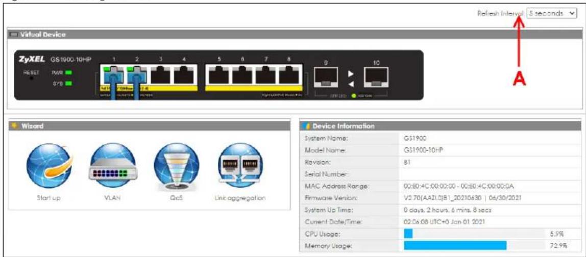
The following table describes the labels in this screen.
Table 16 Getting Started
| LABEL DESCRIPTION | |
| Refresh Interval (A) | Use the drop-box to select: None, 5 seconds, 10 seconds, 15 seconds, 20 seconds, 25 seconds, or 30 seconds. |
| Virtual Device Displays | an image of the Switch. |
| Wizard Displays the following links: Start up, VLAN, QoS, and Link aggregation. | |
| Device Information | |
| System Name This field displays the name used to identify the Switch on any network. | |
| Model Name This field displays the model name of this Switch. | |
| Revision This field displays the hardware revision number of this Switch. | |
| Serial Number This field displays the serial number of this Switch. | |
| MAC Address Range | This field displays the MAC addresses used by the Switch. Each physical port or wireless radio has one MAC address. The first MAC address is assigned to the Ethernet LAN port, the second MAC address is assigned to the first radio, and so on. |
| Firmware Version | This field displays the version number and date of the firmware the Switch is currently running. |
| System Up Time This field displays how long the Switch has been running since it last restarted or was turned on. | |
| Current Date/Time | This field displays the current date and time in the Switch. The format is hh:mm:ss yyyy-mm-dd. |
| CPU Usage This field displays the Switch's recent CPU usage. | |
| Memory Usage This field displays the Switch's recent memory usage. | |
6.2.1 Wizard
Wizard displays start up, VLAN, QoS, and link aggregation.
For details on Wizard features, see system Chapter 7 on page 74, VLAN Chapter 9 on page 86, QoS Chapter 29 on page 198, and link aggregation Chapter 11 on page 95.
Start up
In start up, you can set up IP or DNS, set up your user name or password, and view finished results.
In order to set up your IP or DNS, please do the following. Click Getting Started > Start up > 1 Step 1 Set up IP to access this screen.
Figure 75 Getting Started > Start up > 1 Step 1 Set up IP
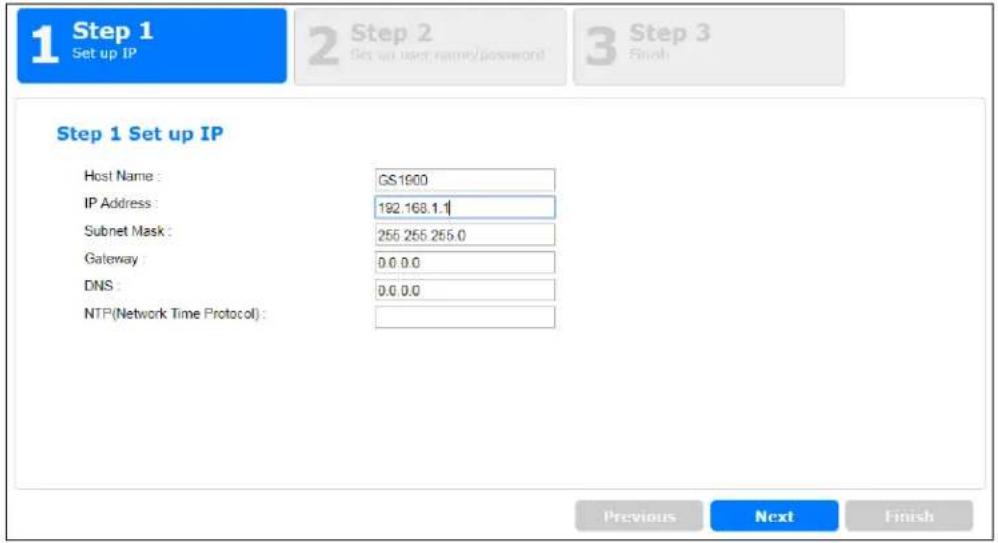
Each field is described in the following table.
Table 17 Getting Started > Start up > 1 Step 1 Set up IP
| LABEL DESCRIPTION | |
| Host Name This field displays a host name. | |
| IP Address | The Switch needs an IP address for it to be managed over the network. The factory default IP address is 192.168.1.1. |
| Subnet Mask The subnet mask specifies the network number portion of an IP address.The factory default subnet mask is 255.255.255.0. | |
| Gateway | Type the IP address of the default outgoing gateway in dotted decimal notation, for example 192.168.1.254. |
| DNS | DNS (Domain Name System) is for mapping a domain name to its corresponding IP address and vice versa. Enter a domain name server IP address in order to be able to use a domain name instead of an IP address. |
| NTP (Network Time Protocol) | This field displays the NTP time servers from which the Switch gets the time and date. |
| Next | Click Next to show the next screen. |
After clicking Next, the set up your user name screen appears.
Figure 76 Getting Started > Start up > 2 Step 2 Set up user name/password
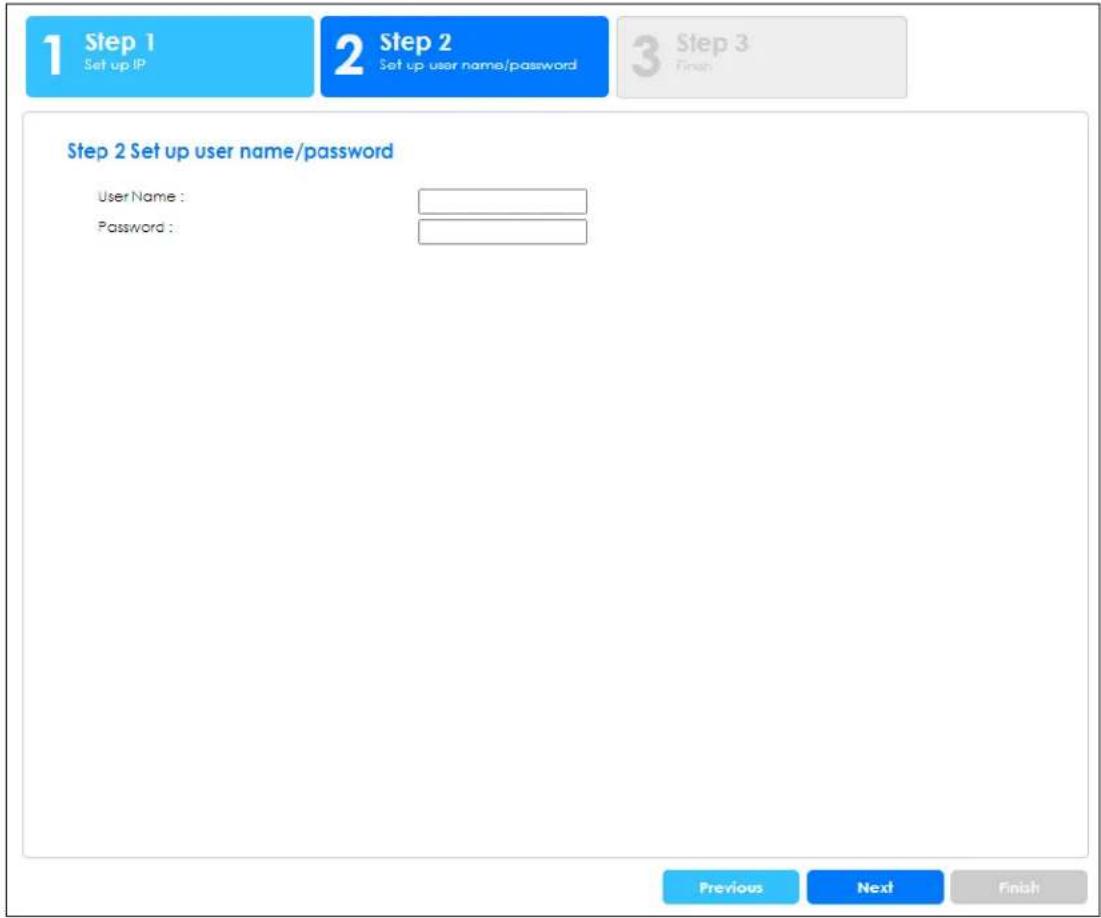
Each field is described in the following table.
Table 18 Getting Started > Start up > 2 Step 2 Set up user name/password
| LABEL DESCRIPTION | |
| Username | The default user name isadminand associated default password is1234.Enter a user name using the keyboard characters ("a-z", "A-Z", "0-9", ~!@#%^&*()_+'-=[]::<>./\) for the user. The allowed string length is 1 to 32. |
| Password | The default user name isadminand associated default password is1234.Enter a new password using the keyboard characters ("a-z", "A-Z", "0-9", ~!@#%^&*()_+'-={}[]::<>./\) for the user. The allowed string length is 1 to 64. |
| Previous Click Previous | to show the previous screen. |
| Next | ClickNextto show the next screen. |
After clicking Next, the finish screen appears.
Figure 77 Getting Started > Start up > 3 Step 3 Finish
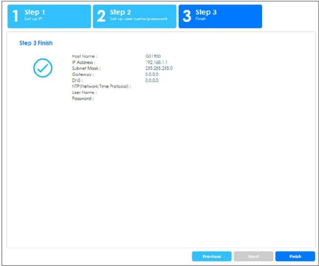
Each field is described in the following table.
Table 19 Getting Started > Start up > 3 Step 3 Finish
| LABEL DESCRIPTION | |
| Host Name This field displays a host name. | |
| IP Address | The Switch needs an IP address for it to be managed over the network. The factory default IP address is 192.168.1.1. |
| Subnet Mask The subnet mask specifies the network number portion of an IP address.The factory default subnet mask is 255.255.255.0. | |
| Gateway | Type the IP address of the default outgoing gateway in dotted decimal notation, for example 192.168.1.254. |
| DNS | DNS (Domain Name System) is for mapping a domain name to its corresponding IP address and vice versa. Enter a domain name server IP address in order to be able to use a domain name instead of an IP address. |
| NTP (Network Time Protocol) | This field displays the NTP time servers from which the Switch gets the time and date. |
| Username | The default user name isadminand associated default password is1234. |
| Password | The default user name isadminand associated default password is1234. |
| Previous Click Previous | to show the previous screen. |
| Finish | Review the information and clickFinishto create the task. |
VLAN
In VLAN, you can create VLAN, tag VLAN setting, and view finished results.
In order to create VLAN, please do the following. Click Getting Started > VLAN > 1 Step 1 Create VLAN to access this screen.
Figure 78 Getting Started > VLAN > 1 Step 1 Create VLAN
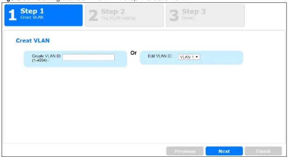
Each field is described in the following table.
Table 20 Getting Started > VLAN > 1 Step 1 Create VLAN
| LABEL DESCRIPTION | |
| Create VLAN ID (1-4094) | Type a number between 1 and 4094 to create a VLAN ID. |
| Edit VLAN ID Select from the drop-box a VLAN ID. | |
| Next | Click Next to show the next screen. |
After clicking Next, the tag VLAN setting screen appears.
Figure 79 Getting Started > VLAN > 2 Step 2 Tag VLAN Setting
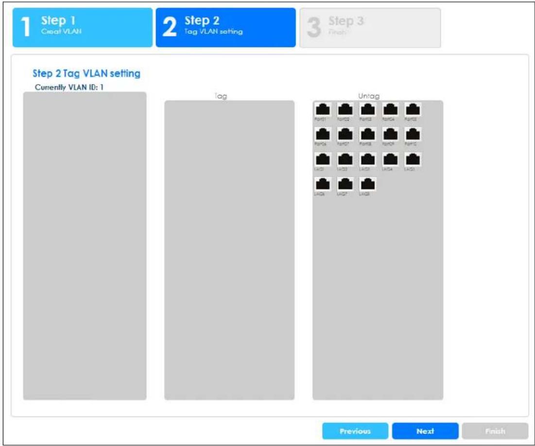
flowchart
graph TD
    A["Step 1<br>Croat VLAN"] --> B["Step 2<br>Tag VLAN setting"]
    B --> C["Step 3<br>Finish"]
    D["Step 2 Tag VLAN setting<br>Currently VLAN ID: 1"] --> E["Tag"]
    E --> F["Untag"]
    F --> G["Previous"]
    F --> H["Next"]
    F --> I["Finish"]
Each field is described in the following table.
Table 21 Getting Started > VLAN > 2 Step 2 Tag VLAN Setting
| LABEL DESCRIPTION | |
| Currently VLAN ID This field | displays the VLAN identification number. |
| Tag Ports belonging to the | specified VLAN tag all outgoing frames transmitted. |
| Untag | Ports belonging to the specified VLAN do not tag all outgoing frames transmitted. |
| Previous Click Previous to show the previous screen. | |
| Next Click Next to show the next screen. | |
After clicking Next, the finish screen appears.
Figure 80 Getting Started > VLAN > 3 Step 3 Finish
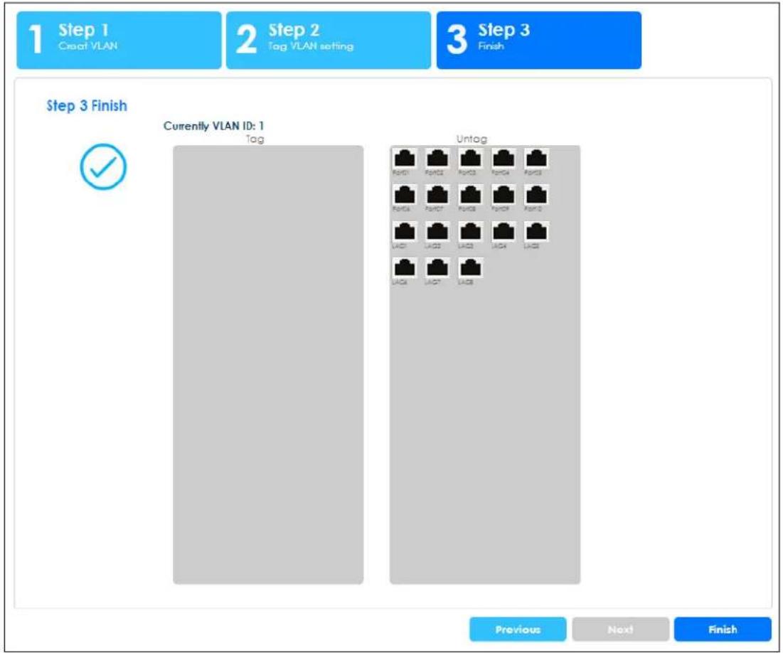
flowchart
graph TD
    A["Step 1<br>Create VLAN"] --> B["Step 2<br>Tag VLAN setting"]
    B --> C["Step 3<br>Finish"]
    D["Currently VLAN ID: 1"] --> E["Tag"]
    D --> F["Untag"]
    E --> G["Previous"]
    F --> H["Next"]
    F --> I["Finish"]
Each field is described in the following table.
Table 22 Getting Started > VLAN > 3 Step 3 Finish
| LABEL DESCRIPTION | |
| Currently VLAN ID This field displays the VLAN identification number. | |
| Tag Ports belonging to the specified VLAN tag all outgoing frames transmitted. | |
| Untag Ports belonging to the specified VLAN do not tag all outgoing frames transmitted. | |
| Previous Click Previous to show the previous screen. | |
| Finish | Review the information and click Finish to create the task. |
QoS
In QoS, you can create QoS settings, and view finished results.
In order to create QoS settings, please do the following. Click Getting Started > QoS > 1 Step 1 QoS (Quality of Service) to access this screen.
Figure 81 Getting Started > QoS > 1 Step 1 QoS (Quality of Service)
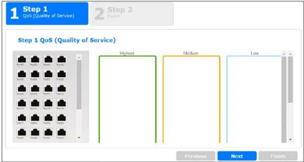
flowchart
graph TD
    A["Step 1 QoS (Quality of Service)"] --> B["Highest"]
    A --> C["Medium"]
    A --> D["Low"]
Each field is described in the following table.
Table 23 Getting Started > QoS > 1 Step 1 QoS (Quality of Service)
| LABEL DESCRIPTION | |
| Highest Click and drag icons located on the left to desired preference. | |
| Medium Click and drag icons located on the left to desired preference. | |
| Low Click and drag icons located on the left to desired preference. | |
| Next | Click Next to show the next screen. |
After clicking Next, the finish screen appears.
Figure 82 Getting Started > QoS > 2 Step 2 Finish
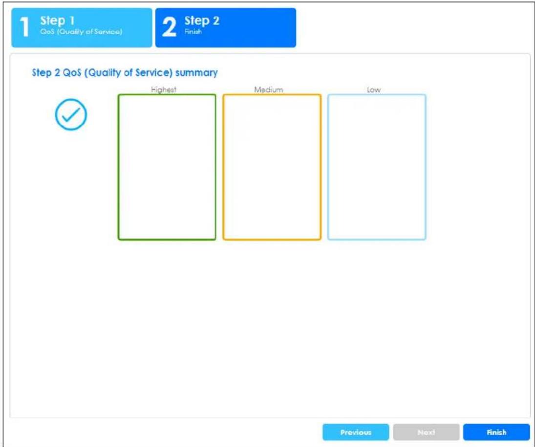
Each field is described in the following table.
Table 24 Getting Started > QoS > 2 Step 2 Finish
| LABEL DESCRIPTION | |
| Highest Displays summary results. | |
| Medium Displays summary results. | |
| Low Displays summary results. | |
| Previous Click Previous to show the previous screen. | |
| Finish | Review the information and click Finish to create the task. |
Link Aggregation
In link aggregation, you can link aggregation and view finished results.
In order to create link aggregation settings, please do the following. Click Getting Started > Link aggregation > 1 Step 1 Link aggregation to access this screen.
Figure 83 Getting Started > Link aggregation > 1 Step 1 Link aggregation
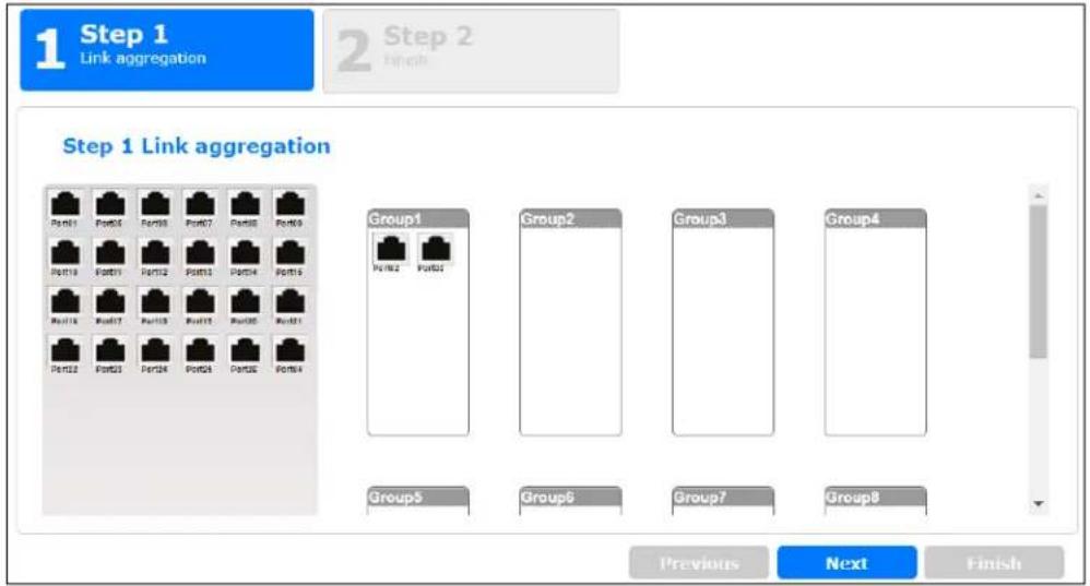
flowchart
graph TD
    A["Step 1 Link aggregation"] --> B["Port1"]
    A --> C["Port2"]
    A --> D["Port3"]
    A --> E["Port4"]
    A --> F["Port5"]
    A --> G["Port6"]
    A --> H["Port7"]
    A --> I["Port8"]
    A --> J["Port9"]
    K["Previous"] --> L["Next"]
    L --> M["Finish"]
Each field is described in the following table.
Table 25 Getting Started > Link aggregation > 1 Step 1 Link aggregation
| LABEL DESCRIPTION | |
| Group 1 Click and drag icons located on the left to desired preference. | |
| Group 2 Click and drag icons located on the left to desired preference. | |
| Group 3 Click and drag icons located on the left to desired preference. | |
| Group 4 Click and drag icons located on the left to desired preference. | |
| Group 5 Click and drag icons located on the left to desired preference. | |
| Group 6 Click and drag icons located on the left to desired preference. | |
| Group 7 Click and drag icons located on the left to desired preference. | |
| Group 8 Click and drag icons located on the left to desired preference. | |
| Next | Click Next to show the next screen. |
After clicking Next, the finish screen appears.
Figure 84 Getting Started > Link aggregation > 2 Step 2 Finish
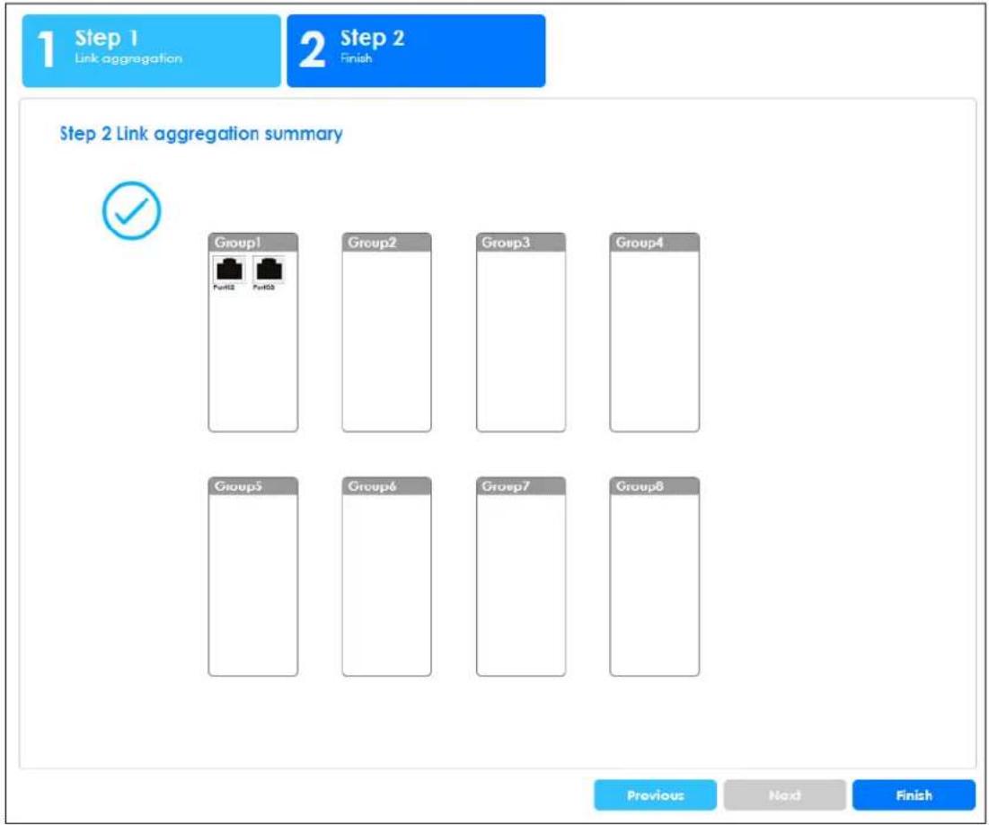
Each field is described in the following table.
Table 26 Getting Started > Link aggregation > 2 Step 2 Finish
| LABEL DESCRIPTION | |
| Group 1 Displays summary results. | |
| Group 2 Displays summary results. | |
| Group 3 Displays summary results. | |
| Group 4 Displays summary results. | |
| Group 5 Displays summary results. | |
| Group 6 Displays summary results. | |
| Group 7 Displays summary results. | |
| Group 8 Displays summary results. | |
| Previous Click Previous to show the previous screen. | |
| Finish | Review the information and click Finish to create the task. |
PART II
Technical Reference
CHAPTER 7
Monitor: System
7.1 Overview
This section provides information for System in Monitor. Use the System screens to view general Switch settings.
7.1.1 What You Can Do in this Chapter
- The IP screen (Section 7.2 on page 74) displays IPv4 and IPv6.
- The Information screen (Section 7.3 on page 75) displays the system information.
7.2 IP Settings
The Switch needs an IP address for it to be managed over the network. The factory default IP address is 192.168.1.1. The subnet mask specifies the network number portion of an IP address. The factory default subnet mask is 255.255.255.0.
7.2.1 IPv4 Settings
Use this screen to view the Switch's IPv4 information. Click Monitor > System > IP > IPv4 to open this screen.
Figure 85 Monitor > System > IP > IPv4
| IPv4 Information | IPv4 | IPv6 | |
| DHCP State | Disable | ||
| IP Address | 10.214.80.211 | ||
| Subnet Mask | 255.255.255.0 | ||
| Gateway | 0.0.0.0 | ||
| DNS Server 1 | 0.0.0.0 | ||
| DNS Server 2 | 0.0.0.0 | ||
| Management VLAN | 1 |
The following table describes the labels in this screen.
Table 27 Monitor > System > IP > IPv4
| LABEL DESCRIPTION | |
| DHCP State | This field displays the state of Dynamic Host Configuration Protocol RFC 2131 and RFC 2132 (DHCP). |
| IP Address | This field displays IP address of the Switch in the IP domain. |
| Subnet Mask | This field displays the subnet mask of the Switch in the IP domain. |
| Gateway | This field displays the IP address of the default outgoing gateway in dotted decimal notation, for example 192.168.1.254. |
| DNS Server 1 | DNS (Domain Name System) is for mapping a domain name to its corresponding IP address and vice versa. This field displays a domain name server IP address, enabling the use of a domain. |
| DNS Server 2 | DNS (Domain Name System) is for mapping a domain name to its corresponding IP address and vice versa. This field displays a domain name server IP address, enabling the use of a domain. |
| Management VLAN | This field displays the management VLAN. |
7.2.2 IPv6 Settings
Use this screen to view the Switch's IPv6 information. Click Monitor > System > IP > IPv6 to open this screen.
Figure 86 Monitor > System > IP > IPv6
| IPv6 Information | IPv4 | IPv6 | |
| Auto Configuration | Enable | ||
| IPv6 Address | fe80::4e9e:ffff:fe72:4a87 / 64 | ||
| IPv6 Gateway | :: | ||
| DHCPv6 Client | Disable |
The following table describes the labels in this screen.
Table 28 Monitor > System > IP > IPv6
| LABEL DESCRIPTION | |
| Auto Configuration | This field displays auto configuration. |
| IPv6 Address | This field displays IP address of the Switch in the IP domain. |
| IPv6 Gateway | This field displays the IP address of the default outgoing gateway. |
| DHCPv6 Client | This field displays the Switch’s DHCP settings when it is acting as a DHCPv6 client. |
7.3 Information
In the navigation panel, click Monitor > System > Information > System Information to display the screen as shown. You can view system information.
Figure 87 Monitor > System > Information > System Information
| System Information | |
| System Name | GS1900 |
| System Location | Location |
| System Contact | Contact |
The following table describes the labels in this screen.
Table 29 Monitor > System > Information > System Information
| LABEL DESCRIPTION | |
| System Name | This field displays the descriptive name of the Switch for identification purposes. |
| System Location | This field displays the geographic location of the Switch for identification purposes. |
| System Contact | This field displays the person in charge of the Switch for identification purposes. |
CHAPTER 8
Monitor: Port
8.1 Overview
This section provides information for Port in Monitor. Use the Port screens to view general Switch port settings.
8.1.1 What You Can Do in this Chapter
- The Port screen (Section 8.2 on page 77) displays status, port counters, and bandwidth utilization.
• The PoE screen (Section 8.3 on page 81) displays PoE. - The Bandwidth Management screen (Section 8.4 on page 83) displays bandwidth control.
- The Storm Control screen (Section 8.5 on page 84) displays port settings of the Switch.
8.2 Port Settings
Use this screen to view Switch port settings.
8.2.1 Status
Use this screen to view the Switch's port statistics. Click Monitor > Port > Port > Status to access this screen.
Figure 88 Monitor > Port > Port > Status
| Status | Status Port Counters Bandwidth Utilization | ||||||
| Port | Port Name | State | Link Status | Speed | Duplex | FlowCtrl Status | Type |
| 1 | Enable | Down | Auto | Auto | Disable | Copper | |
| 2 | Enable | Down | Auto | Auto | Disable | Copper | |
| 3 | Enable | Down | Auto | Auto | Disable | Copper | |
| 4 | Enable | Down | Auto | Auto | Disable | Copper | |
| 5 | Enable | Down | Auto | Auto | Disable | Copper | |
| 6 | Enable | Down | Auto | Auto | Disable | Copper | |
| 7 | Enable | Down | Auto | Auto | Disable | Copper | |
| 8 | Enable | Down | Auto | ||||
| 21 | Enable | Down | Auto | Auto | Disable | Copper | |
| 22 | Enable | Up | Auto-1000M | Auto-full | Disable | Copper | |
| 23 | Enable | Down | Auto | Auto | Disable | Copper | |
| 24 | Enable | Up | Auto-1000M | Auto-full | Disable | Copper | |
| 25 | Enable | Down | Auto | Auto | Disable | Fiber | |
| 26 | Enable | Down | Auto | Auto | Disable | Fiber | |
Each field is described in the following table.
Table 30 Monitor > Port > Port > Status
| LABEL DESCRIPTION | |
| Port This is the port index number. | |
| Port Name A descriptive name that identifies this port. | |
| State This is port admin setting state. | |
| Link Status | This field displaysUp, Down or Not Present. It displaysUpwhen the port is linked up orDown when it is not. When no any physical port is binding with this group, it displaysNot Present. |
| Speed View the speed of the Ethernet connection on this port. | |
| Duplex View the duplex mode of the Ethernet connection on this port. | |
| FlowCtrl Status A concentration of traffic on a port decreases port bandwidth and overflows buffer memory causing packet discards and frame losses. Flow Control is used to regulate transmission of signals to match the bandwidth of the receiving port. | |
| Type View the type on this port. | |
8.2.2 Port Counters
Use this screen to view the Switch's port counters settings. Click Monitor > Port > Port > Port Counters to access this screen.
Figure 89 Monitor > Port > Port > Port Counters (Port 1 Interface mib Counters)
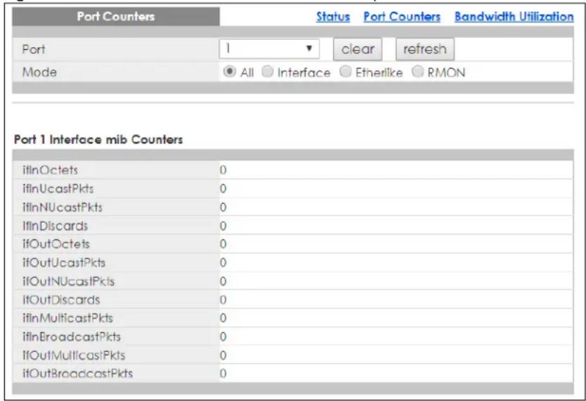
Figure 90 Monitor > Port > Port > Port Counters (Port 1 Etherlike mib Counters)
| Port 1 Etherlike mib Counters | |
| dot3StatsAlignmentErrors | 0 |
| dot3StatsFCSErrors | 0 |
| dot3StatsSingleCollisionFrames | 0 |
| dot3StatsMultipleCollisionFrames | 0 |
| dot3StatsDeferredTransmissions | 0 |
| dot3StatsLateCollisions | 0 |
| dot3StatsExcessive Collisions | 0 |
| dot3StatsFrameTooLongs | 0 |
| dot3StatsSymbolErrors | 0 |
| dot3ControlInUnknownOpcodes | 0 |
| dot3InPauseFrames | 0 |
| dot3OutPauseFrames | 0 |
Figure 91 Monitor > Port > Port > Port Counters (Port 1 RMON mib Counters)
| Port 1 RMON mib Counters | |
| etherStatsDropEvents | 0 |
| etherStatsOctets | 0 |
| etherStatsPkts | 0 |
| etherStatsBroadcastPkts | 0 |
| etherStatsMulticastPkts | 0 |
| etherStatsCRCAlignErrors | 0 |
| etherStatsUnderSizePkts | 0 |
| etherStatsOverSizePkts | 0 |
| etherStatsFragments | 0 |
| etherStatsJabbers | 0 |
| etherStatsCollisions | 0 |
| etherStatsPkts64Octets | 0 |
| etherStatsPkts65to127Octets | 0 |
| etherStatsPkts128to255Octets | 0 |
| etherStatsPkts256to511Octets | 0 |
| etherStatsPkts512to1023Octets | 0 |
| etherStatsPkts1024to1518Octets | 0 |
Each field is described in the following table.
Table 31 Monitor > Port > Port > Port Counters
| LABEL DESCRIPTION | |
| Port Counters | |
| Port This field displays the port. | |
| Mode This field displays the mode. | |
| Port 1 Interface mib Counters | |
| ifInOctets This field displays the ifInOctets. | |
| ifInUcastPkts This field displays the ifInUcastPkts. | |
| ifInNUcastPkts This field displays the ifInNUcastPkts. | |
| ifInDiscards This field displays the ifInDiscards. | |
| ifOutOctets This field displays the ifOutOctets. | |
| ifOutUcastPkts This field displays the ifOutUcastPkts. | |
| ifOutNUcastPkts This field displays the ifOutNUcastPkts. | |
| ifOutDiscards This field displays the ifOutDiscards. | |
| ifInMulticastPkts This field displays the ifInMulticastPkts. | |
| ifInBroadcastPkts This field displays the ifInBroadcastPkts. | |
| LABEL | DESCRIPTION |
| ifOutMulticastPkts This field displays the ifOutMulticastPkts. | |
| ifOutBroadcastPkts This field displays the ifOutBroadcastPkts. | |
| Port 1 Etherlike mib Counters | |
| dot3StatsAlignmentErrors This field displays the dot3StatsAlignmentErrors. | |
| dot3StatsFCSErrors This field displays the dot3StatsFCSErrors. | |
| dot3StatsSingleCollisionFrames | This field displays the dot3StatsSingleCollisionFrames. |
| dot3StatsMultipleCollisionFrames This field displays the dot3StatsMultipleCollisionFrames. | |
| dot3StatsDeferredTransmissions This field displays the dot3StatsDeferredTransmissions. | |
| dot3StatsLateCollisions This field displays the dot3StatsLateCollisions. | |
| dot3StatsExcessiveCollisions This field displays the dot3StatsExcessiveCollisions. | |
| dot3StatsFrameTooLongs This field displays the dot3StatsFrameTooLongs. | |
| dot3StatsSymbolErrors This field displays the dot3StatsSymbolErrors. | |
| dot3ControllInUnkownOpcodes This field displays the dot3ControllInUnkownOpcodes. | |
| dot3IInPauseFrames This field displays the dot3IInPauseFrames. | |
| dot3IOutPauseFrames This field displays the dot3IOutPauseFrames. | |
| Port 1 RMON mib Counters | |
| etherStatsDropEvents | This field displays the etherStatsDropEvents. |
| etherStatsOctets | This field displays the etherStatsOctets. |
| etherStatsPkts | This field displays the etherStatsPkts. |
| etherStatsBroadcastPkts | This field displays the etherStatsBroadcastPkts. |
| etherStatsMulticastPkts This field displays the etherStatsMulticastPkts. | |
| etherStatsCRCAignErrors This field displays the etherStatsCRCAignErrors. | |
| etherStatsUnderSizePkts | This field displays the etherStatsUnderSizePkts. |
| etherStatsOverSizePkts | This field displays the etherStatsOverSizePkts. |
| etherStatsFragments | This field displays the etherStatsFragments. |
| etherStatsJabbers | This field displays the etherStatsJabbers. |
| etherStatsCollisions This field displays the etherStatsCollisions. | |
| etherStatsPkts64Octets This field displays the etherStatsPkts64Octets. | |
| etherStatsPkts65to127Octets | This field displays the etherStatsPkts65to127Octets. |
| etherStatsPkts128to255Octets | This field displays the etherStatsPkts128to255Octets. |
| etherStatsPkts256to511Octets | This field displays the etherStatsPkts256to511Octets. |
| etherStatsPkts512to1023Octets | This field displays the etherStatsPkts512to1023Octets. |
| etherStatsPkts1024to1518Octets | This field displays the etherStatsPkts1024to1518Octets. |
8.2.3 Bandwidth Utilization
Utilization is the percentage of a network's bandwidth that is currently being consumed by network traffic. Each vertical bar represents the highest utilization on a port, and can be either transmitted (Tx) traffic or received (Rx) traffic during the last time interval in seconds.
Use this screen to view the Switch's bandwidth utilization settings. Click Monitor > Port > Port > Bandwidth Utilization to access this screen.
Figure 92 Monitor > Port > Port > Bandwidth Utilization
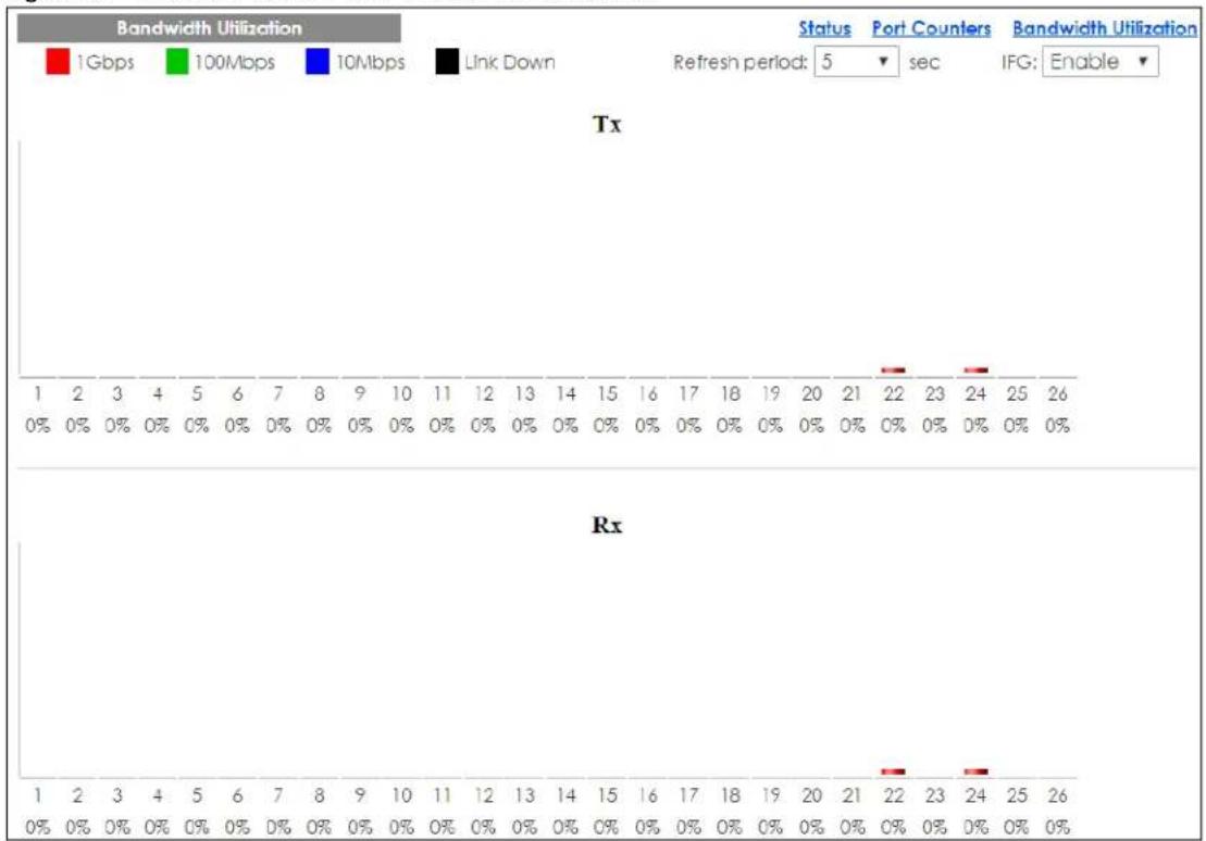
Each field is described in the following table.
Table 32 Monitor > Port > Port > Bandwidth Utilization
| LABEL DESCRIPTION | |
| Bandwidth Utilization | |
| 1Gbps This field displays the 1 Gbps. | |
| 100Mbps This field displays the 100 Mbps. | |
| 10Mbps This field displays the 10 Mbps. | |
| Link down This field displays the link down. | |
| Refresh period This field displays the refresh period. | |
| IFG This field displays the IFG. | |
| Tx Transmitted (Tx) traffic during the last time interval in seconds. | |
| Rx Received (Rx) traffic during the time interval in seconds. | |
8.3 PoE Settings
Note: The PoE function and the following screens are available for models ending in "HP" only.
The Switch supports both the IEEE 802.3af Power over Ethernet (PoE) and IEEE 802.3at High Power over Ethernet (PoE) standards. The Switch is Power Sourcing Equipment (PSE) because it provides a source of power through its Ethernet ports, and each device that receives power through an Ethernet port is a
Powered Device (PD).
In the figure below, the IP camera and IP phone get their power directly from the Switch. Aside from minimizing the need for cables and wires, PoE removes the hassle of trying to find a nearby electric outlet to power up devices.
Figure 93 Powered Device Examples
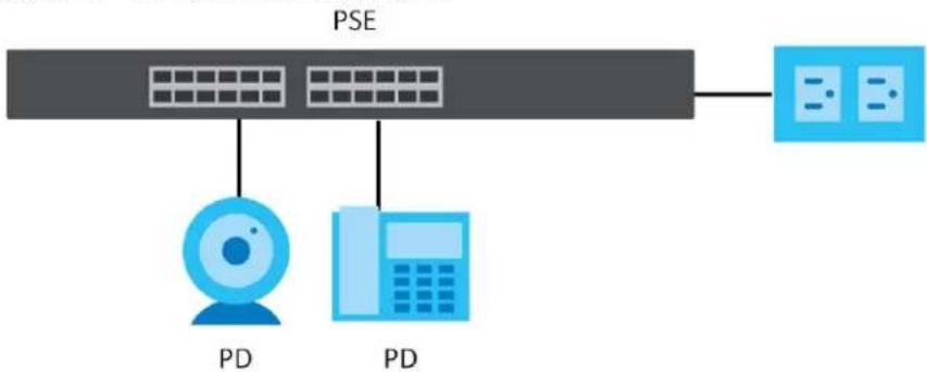
flowchart
graph TD
    A["PSE"] --> B["Server"]
    A --> C["PD"]
    A --> D["PD"]
You can also set priorities so that the Switch is able to reserve and allocate power to certain PDs.
Note: The PoE devices that supply or receive power and their connected Ethernet cables must all be completely indoors.
To view the current amount of power that PDs are receiving from the Switch, click Monitor > Port > PoE.
Figure 94 Monitor > Port > PoE
| PoE | ||||
| PoE Mode | Total Power(W) | Consuming Power(W) | Allocated Power(W) | Remaining Power(W) |
| Consumption | 170.0 | 0.0 | 0.0 | 170.0 |
Each field is described in the following table.
Table 33 Monitor > Port > PoE
| LABEL DESCRIPTION | |
| PoE Mode | This field displays the power management mode used by the Switch, whether it is in Classification or Consumption mode. |
| Total Power(W) | This field displays the total power the Switch can provide to the connected PoE-enabled devices on the PoE ports. The total power of GS1900-10HP is 77 W and GS1900-8HP is 70 W. |
| Consuming Power(W) | This field displays the total amount of power the Switch is currently supplying to the connected PoE-enabled devices. |
| Allocated Power(W) | This field displays the total amount of power the Switch (in Classification mode) has reserved for PoE after negotiating with the connected PoE devices. It shows NA when the Switch is in Consumption mode.Consuming Power (W) can be less than or equal but not more than the Allocated Power (W). |
| Remaining Power(W) | This field displays the amount of power the Switch can still provide for PoE.Note: The Switch must have at least 16 W of remaining power in order to supply power to a PoE device, even if the PoE device needs less than 16 W. |
8.4 Bandwidth Management
This section shows you the maximum bandwidth using the Bandwidth Management screen. Bandwidth management shows the maximum allowable bandwidth for incoming and/or out-going traffic flows on a port.
8.4.1 Bandwidth Control
Use this screen to view the Switch's bandwidth control in egress global burst and port rate.
An egress port is an outgoing port, that is, a port through which a data packet leaves for both ports. An ingress port is an incoming port, that is, a port through which a data packet enters.
Click Monitor > Port > Bandwidth Management > Bandwidth Control to access this screen.
Figure 95 Monitor > Port > Bandwidth Management > Bandwidth Control
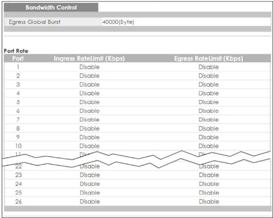
Each field is described in the following table.
Table 34 Monitor > Port > Bandwidth Management > Bandwidth Control
| LABEL DESCRIPTION | |
| Bandwidth Control | |
| Egress Global Burst | This field specifies the current egress burst size in bytes all ports. |
| Port Rate | View the maximum bandwidth allowed in kilobits per second (Kbps) for the traffic flow on a port. |
| Port This field displays the port number. | |
| Ingress RateLimit (Kbps) | View the maximum bandwidth allowed in kilobits per second (Kbps) for the incoming traffic flow on a port. |
| Egress RateLimit (Kbps) | View the maximum bandwidth allowed in kilobits per second (Kbps) for the out-going traffic flow on a port. |
8.5 Storm Control
This section shows you the storm control feature.
Storm control limits the number of broadcast, multicast and unicast packets the Switch receives per second on the ports. When the maximum number of allowable broadcast, multicast and/or unicast packets is reached per second, the subsequent packets are discarded. Enabling this feature reduces broadcast, multicast and/or unicast packets in your network. You can specify limits for each packet type on each port.
Click Monitor > Port > Storm Control to access this screen.
Figure 96 Monitor > Port > Storm Control
| Storm Control | |||||
| Port | State | Broadcast (pps) | Unknown Multicast (pps) | Unknown Unicast (pps) | Action |
| 1 | Disable | Disable | Disable | Disable | Drop |
| 2 | Disable | Disable | Disable | Disable | Drop |
| 3 | Disable | Disable | Disable | Disable | Drop |
| 4 | Disable | Disable | Disable | Disable | Drop |
| 5 | Disable | Disable | Disable | Disable | Drop |
| 6 | Disable | Disable | Disable | Disable | Drop |
| 7 | Disable | Disable | Disable | Disable | Drop |
| 8 | Disable | Disable | Disable | Disable | Drop |
| 9 | Disable | Disable | Disable | Disable | Drop |
| 10 | Disable | Disable | Disable | Disable | Drop |
| 11 | Disable | Disable | Disable | Disable | Drop |
| 12 | Disable | Disable | Disable | Disable | Drop |
| 13 | Disable | Disable | Disable | Disable | Drop |
| 14 | Disable | Disable | Disable | Disable | Drop |
| 15 | Disable | Disable | Disable | Disable | Drop |
| 16 | Disable | Disable | Disable | Disable | Drop |
| 17 | Disable | Disable | Disable | Disable | Drop |
| 18 | Disable | Disable | Disable | Disable | Drop |
| 19 | Disable | Disable | Disable | Disable | Drop |
| 20 | Disable | Disable | Disable | Disable | Drop |
| 21 | Disable | Disable | Disable | Disable | Drop |
| 22 | Disable | Disable | Disable | Disable | Drop |
| 23 | Disable | Disable | Disable | Disable | Drop |
| 24 | Disable | Disable | Disable | Disable | Drop |
| 25 | Disable | Disable | Disable | Disable | Drop |
| 26 | Disable | Disable | Disable | Disable | Drop |
Each field is described in the following table.
Table 35 Monitor > Port > Storm Control
| LABEL DESCRIPTION | |
| Storm Control | |
| Port This field displays the port number. | |
| State This field displays the state. | |
| Broadcast (pps) Displays how many broadcast packets the port receives (in pps). | |
| Unknown Multicast (pps) | Displays how many unknown multicast packets the port receives (in pps). |
| Unknown Unicast (pps) | Displays how many unknown unicast packets the port receives (in pps). |
| Action | Displays the action the device takes when a limit is reached. The following options are available:Drop – drop the packet.Shutdown – shutdown the connection. |
9.1 Overview
This section provides information for VLAN in Monitor.
A VLAN (Virtual Local Area Network) allows a physical network to be partitioned into multiple logical networks. Devices on a logical network belong to one group. A device can belong to more than one group. With VLAN, a device cannot directly talk to or hear from devices that are not in the same groups; the traffic must first go through a router.
In MTU (Multi-Tenant Unit) applications, VLAN is vital in providing isolation and security among the subscribers. When properly configured, VLAN prevents one subscriber from accessing the network resources of another on the same LAN, therefore a user will not see the printers and hard disks of another user on the same network.
VLAN also increases network performance by limiting broadcasts to a smaller and more manageable logical broadcast domain. In traditional switched environments, all broadcast packets go to each and every individual port. With VLAN, all broadcasts are confined to a specific broadcast domain.
9.1.1 What You Can Do in this Chapter
- The VLAN screen (Section 9.2 on page 86) displays VLAN, port, and VLAN port settings.
- The Guest VLAN screen (Section 9.3 on page 89) displays the global and port settings of the Switch.
- The Voice VLAN screen (Section 9.4 on page 90) displays the global and port settings of the Switch.
9.2 VLAN Settings
Use this screen to view Switch VLAN settings.
9.2.1 VLAN
Use this screen to view the Switch's VLAN settings. Click Monitor > VLAN > VLAN > VLAN to access this screen.
Figure 97 Monitor > VLAN > VLAN > VLAN
| VLAN | VLAN Port VLAN Port | |
| VLAN ID | VLAN Name | VLAN Type |
| 1 | default | Default |
Each field is described in the following table.
Table 36 Monitor > VLAN > VLAN > VLAN
| LABEL DESCRIPTION | |
| VLAN | |
| VLAN ID This is the VLAN identification number. | |
| VLAN Name Displays a descriptive name for the VLAN for identification purposes. | |
| VLAN Type Displays a type for the VLAN for identification purposes. | |
9.2.2 Port
Use this screen to view the Switch's port setting in VLAN. Click Monitor > VLAN > VLAN > Port to access this screen.
Figure 98 Monitor > VLAN > VLAN > Port
| Port | VLAN Port VLAN Port | |||
| Port | PVID | Accept Frame Type | Ingress Check | VLAN Trunk |
| 1 | 1 | ALL | Disable | Disable |
| 2 | 1 | ALL | Disable | Disable |
| 3 | 1 | ALL | Disable | Disable |
| 4 | 1 | ALL | Disable | Disable |
| 5 | 1 | ALL | Disable | Disable |
| 6 | 1 | ALL | Disable | Disable |
| 7 | 1 | ALL | Disable | Disable |
| 8 | 1 | ALL | Disable | Disable |
| 9 | 1 | ALL | Disable | Disable |
| 10 | 1 | Disable | ||
| ALL | Disable | Disable | ||
| 21 | 1 | ALL | Disable | Disable |
| 22 | 1 | ALL | Disable | Disable |
| 23 | 1 | ALL | Disable | Disable |
| 24 | 1 | ALL | Disable | Disable |
| 25 | 1 | ALL | Disable | Disable |
| 26 | 1 | ALL | Disable | Disable |
| LAG1 | 1 | ALL | Disable | Disable |
| LAG2 | 1 | ALL | Disable | Disable |
| LAG3 | 1 | ALL | Disable | Disable |
| LAG4 | 1 | ALL | Disable | Disable |
| LAG5 | 1 | ALL | Disable | Disable |
| LAG6 | 1 | ALL | Disable | Disable |
| LAG7 | 1 | ALL | Disable | Disable |
| LAG8 | 1 | ALL | Disable | Disable |
Each field is described in the following table.
Table 37 Monitor > VLAN > VLAN > Port
| LABEL DESCRIPTION | |
| Port | |
| Port This field displays the port number. | |
| PVID This is the port | VLAN identification number.A PVID (Port VLAN ID) is a tag that adds to incoming untagged frames received on a port so that the frames are forwarded to the VLAN group that the tag defines. |
| Accept Frame Type | This field displays the type that is accepted by the frame.Specifies the type of frames allowed on a port. Choices are All, Tag Only and Untag Only.All accepts all untagged or tagged frames on this port. This is the default setting. Tag Only accepts only tagged frames on this port. All untagged frames will be dropped. Untag Only accepts only untagged frames on this port. All tagged frames will be dropped. |
| Ingress Filter If set, | the Switch discards incoming frames for VLANs that do not have this port as a member. |
| VLAN Trunks | Enable VLAN Trunking on ports connected to other switches or routers (but not ports directly connected to end users) to allow frames belonging to unknown VLAN groups to pass through the Switch. |
9.2.3 VLAN Port
Port-based VLANs are VLANs where the packet forwarding decision is based on the destination MAC address and its associated port. Port-based VLANs require allowed outgoing ports to be defined for each port. Therefore, if you wish to allow two subscriber ports to talk to each other, for example, between conference rooms in a hotel, you must define the egress (an egress port is an outgoing port, that is, a port through which a data packet leaves) for both ports. Port-based VLANs are specific only to the Switch on which they were created.
Use this screen to view the Switch's VLAN port settings. Click Monitor > VLAN > VLAN > VLAN Port to access this screen.
Figure 99 Monitor > VLAN > VLAN > VLAN Port
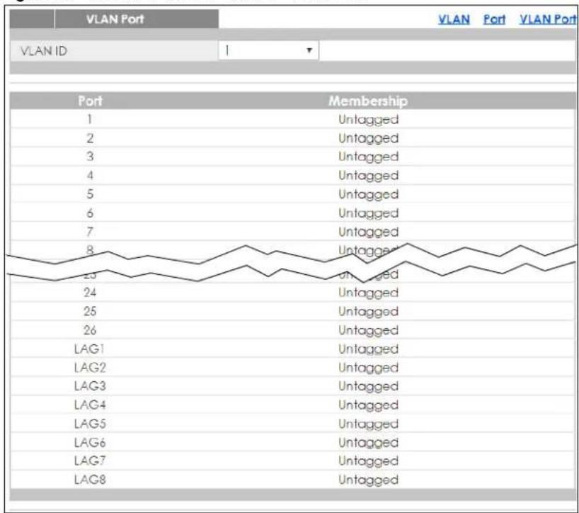
line
| Port | Membership | |---|---| | 1 | Untagged | | 2 | Untagged | | 3 | Untagged | | 4 | Untagged | | 5 | Untagged | | 6 | Untagged | | 7 | Untagged | | 8 | Untagged | | 23 | Untagged | | 24 | Untagged | | 25 | Untagged | | 26 | Untagged | | LAG1 | Untagged | | LAG2 | Untagged | | LAG3 | Untagged | | LAG4 | Untagged | | LAG5 | Untagged | | LAG6 | Untagged | | LAG7 | Untagged | | LAG8 | Untagged |Each field is described in the following table.
Table 38 Monitor > VLAN > VLAN > VLAN Port
| LABEL DESCRIPTION | |
| VLAN Port | |
| VLAN ID This is the VLAN identification number. | |
| Port Displays the port index value. | |
| Membership | Displays the status of the VLAN group: Forbidden, Excluded, Tagged or Untagged. |
9.3 Guest VLAN
When 802.1x port authentication is enabled on the Switch and its ports, clients that do not have the correct credentials are blocked from using the ports. You can configure your Switch to have one VLAN that acts as a guest VLAN. If you enable the guest VLAN (102 in the example) on a port (2 in the example), the user (A in the example) that is not IEEE 802.1x capable or fails to enter the correct user name and password can still access the port, but traffic from the user is forwarded to the guest VLAN. That is, unauthenticated users can have access to limited network resources in the same guest VLAN, such as the Internet. The rights granted to the Guest VLAN depends on how the network administrator configures switches or routers with the guest network feature.
Figure 100 Guest VLAN Example
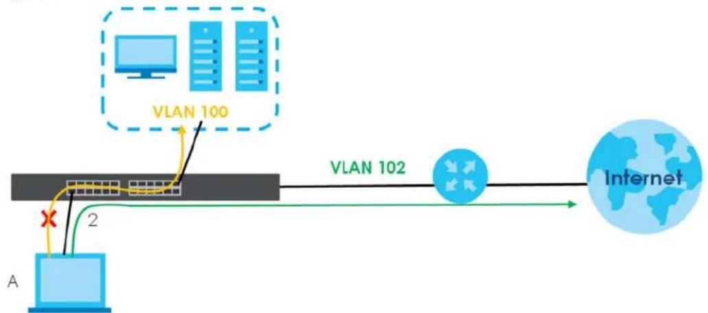
flowchart
graph LR
    A["Server"] -->|VLAN 100| B["VLAN 102"]
    B --> C["Internet"]
    D["Switch"] -->|2| A
    E["Router"] -->|VLAN 100| B
    F["Router"] -->|VLAN 102| B
    style A fill:#cce5ff,stroke:#333
    style B fill:#cce5ff,stroke:#333
    style C fill:#cce5ff,stroke:#333
    style D fill:#cce5ff,stroke:#333
    style E fill:#cce5ff,stroke:#333
    style F fill:#cce5ff,stroke:#333
Use this screen to view the Switch's guest VLAN. Click Monitor > VLAN > Guest VLAN to access this screen.
Figure 101 Monitor > VLAN > Guest VLAN
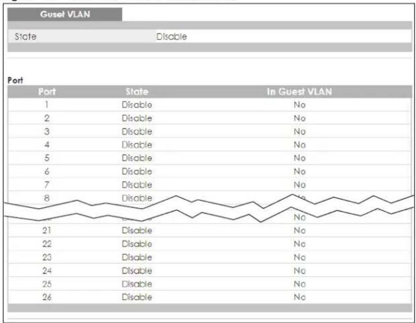
Each field is described in the following table.
Table 39 Monitor > VLAN > Guest VLAN
| LABEL DESCRIPTION | |
| Guest VLAN | |
| State This field displays the state of global guest VLAN. | |
| Port | |
| Port This field displays a port number. | |
| State This field displays the state of a port. | |
| In Guest VLAN | This field displays the status of the port, is the port is in guest VLAN or not. |
9.4 Voice VLAN
Voice VLANs are VLANs configured specially for voice traffic. By adding the ports connected with voice devices to voice VLANs, you can have voice traffic transmitted within voice VLANs and perform QoS-related configuration for voice traffic as required, therefore ensuring the transmission priority of voice traffic and voice quality.
Use this screen to view Switch global and port voice VLAN settings for voice traffic. Click Monitor > VLAN > Voice VLAN to access this screen.
Figure 102 Monitor > VLAN > Voice VLAN
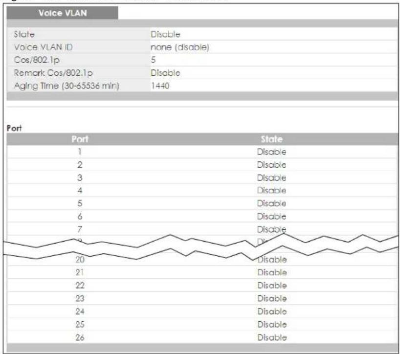
Each field is described in the following table.
Table 40 Monitor > VLAN > Voice VLAN
| LABEL DESCRIPTION | |
| Voice VLAN | |
| State This field displays the state of a port. | |
| Voice VLAN ID This is the voice VLAN identification number. | |
| Cos/802.1p This displays the packet's 802.1p priority field. | |
| Remark Cos/802.1p This field displays the state of the cos/802.1p. | |
| Aging Time (30-65536 min) Displays the time interval (from 30 to 65536) in minutes. | |
| Port | |
| Port This field displays a port number. | |
| State This field displays the state of a port. | |
CHAPTER 10
Monitor: MAC Table
10.1 Overview
This section provides information for MAC Table in Monitor.
The MAC Table screen (a MAC table is also known as a filtering database) shows how frames are forwarded or filtered across the Switch's ports. When a device (which may belong to a VLAN group) sends a packet which is forwarded to a port on the Switch, the MAC address of the device is shown on the Switch's MAC Table. It also shows whether the MAC address is dynamic (learned by the Switch) or static (manually entered in the Static MAC Forwarding screen).
The Switch uses the MAC Table to determine how to forward frames. See the following figure.
1 The Switch examines a received frame and learns the port from which this source MAC address came.
2 The Switch checks to see if the frame's destination MAC address matches a source MAC address already learned in the MAC Table.
- If the Switch has already learned the port for this MAC address, then it forwards the frame to that port.
- If the Switch has not already learned the port for this MAC address, then the frame is flooded to all ports. Too much port flooding leads to network congestion.
- If the Switch has already learned the port for this MAC address, but the destination port is the same as the port it came in on, then it filters the frame.
Figure 103 MAC Table Flowchart
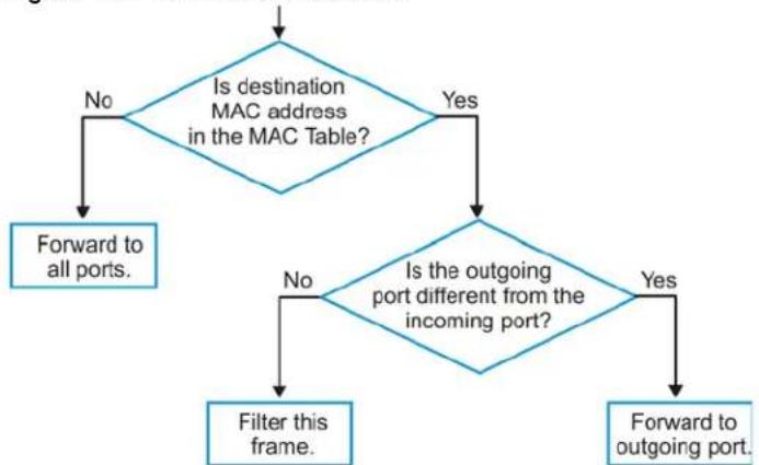
flowchart
graph TD
    A["Is destination MAC address in the MAC Table?"] -->|No| B["Forward to all ports."]
    A -->|Yes| C{Is the outgoing port different from the incoming port?}
    C -->|No| D["Filter this frame."]
    C -->|Yes| E["Forward to outgoing port."]
This link takes you to a screen where you can view the MAC address and VLAN ID of a device attach to a port. You can also view what kind of MAC address it is.
10.1.1 What You Can Do in this Chapter
The MAC Table screen (Section 10.2 on page 93) displays view filter and MAC table of the Switch.
10.2 MAC Table
Use this screen to view filter static and MAC table settings. Click Monitor > MAC Table to access this screen.
Figure 104 Monitor > MAC Table
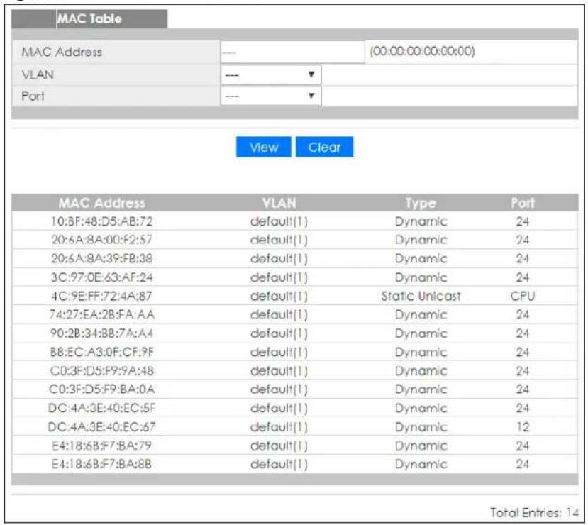
Each field is described in the following table.
Table 41 Monitor > MAC Table
| LABEL DESCRIPTION | |
| MAC Table | |
| MAC Address This is the MAC address of the device from which this incoming frame came. | |
| VLAN Displays a type for the VLAN for identification purposes. | |
| Port This is the port from which the above MAC address was learned. | |
| View This link takes you to a screen where you can view the MAC address and VLAN ID of a device attach to a port. You can also view what kind of MAC address it is. | |
| Clear | Click Clear to return the fields to the factory defaults. |
| MAC Address This is the MAC address of the device from which this incoming frame came. | |
| VLAN Displays a type for the VLAN for identification purposes. | |
| Type | This shows whether the MAC address is dynamic (learned by the Switch) or static (manually entered in the Static MAC Forwarding screen). |
| Port This is the port from which the above MAC address was learned. | |
| Total Entries Displays the number of total entries. | |
CHAPTER 11
Monitor: Link Aggregation
11.1 Overview
This section provides information for Link Aggregation in Monitor.
Link aggregation (trunking) is the grouping of physical ports into one logical higher-capacity link. You may want to trunk ports if for example, it is cheaper to use multiple lower-speed links than to under-utilize a high-speed, but more costly, single-port link. However, the more ports you aggregate then the fewer available ports you have. A trunk group is one logical link containing multiple ports.
The Switch supports both static and dynamic link aggregation.
Note: In a properly planned network, it is recommended to implement static link aggregation only. This ensures increased network stability and control over the trunk groups on your Switch.
11.1.1 What You Can Do in this Chapter
The Link Aggregation screen (Section 11.2 on page 95) displays link aggregation status.
11.2 Link Aggregation
Use the Link Aggregation screens to view Switch link aggregation status. Click Monitor > Link Aggregation to access this screen.
Figure 105 Monitor > Link Aggregation
| Link Aggregation | |||||
| LAG | Name | Type | Link Status | Active Member | Standby Member |
| LAG1 | --- | Not Present | --- | --- | |
| LAG2 | --- | Not Present | --- | --- | |
| LAG3 | --- | Not Present | --- | --- | |
| LAG4 | --- | Not Present | --- | --- | |
| LAG5 | --- | Not Present | --- | --- | |
| LAG6 | --- | Not Present | --- | --- | |
| LAG7 | --- | Not Present | --- | --- | |
| LAG8 | --- | Not Present | --- | --- | |
Each field is described in the following table.
Table 42 Monitor > Link Aggregation
| LABEL DESCRIPTION | |
| LAG Displays the link aggregation status index value. | |
| Name This field displays the name. | |
| Type This field displays the type. | |
| Link Status | This field displays the status of the link. It displaysUpwhen the port is linked up orDownwhen it is not. When no any physical port is binding with this group, it displaysNotPresent. |
| Active Member Displays if this member is an active member of a trunk. | |
| Standby Member Displays if this member is an standby member of a trunk. | |
CHAPTER 12
Monitor: Loop Guard
12.1 Overview
This section provides information for Loop Guard in Monitor.
Loop guard is designed to handle loop problems on the edge of your network. This can occur when a port is connected to a Switch that is in a loop state. Loop state occurs as a result of human error. It happens when two ports on a switch are connected with the same cable. When a switch in loop state sends out broadcast messages the messages loop back to the switch and are re-broadcast again and again causing a broadcast storm.
If a switch (not in loop state) connects to a switch in loop state, then it will be affected by the switch in loop state in the following way:
- It will receive broadcast messages sent out from the switch in loop state.
- It will receive its own broadcast messages that it sends out as they loop back. It will then re-broadcast those messages again.
The following figure shows port N on switch A connected to switch B. Switch B is in loop state. When broadcast or multicast packets leave port N and reach switch B, they are sent back to port N on A as they are rebroadcast from B.
Figure 106 Switch in Loop State
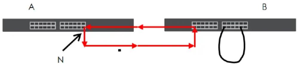
flowchart
graph LR
    A["Path A"] -->|Red Arrow| B["Path B"]
    B -->|Red Arrow| A
    style A fill:#f9f,stroke:#333
    style B fill:#bbf,stroke:#333
    note right of A
        N
    end
The loop guard feature checks to see if a loop guard enabled port is connected to a switch in loop state. This is accomplished by periodically sending a probe packet and seeing if the packet returns on the same port. If this is the case, the Switch will shut down the port connected to the switch in loop state.
The following figure shows a loop guard enabled port N on switch A sending a probe packet P to switch B. Since switch B is in loop state, the probe packet P returns to port N on A. The Switch then shuts down port N to ensure that the rest of the network is not affected by the switch in loop state.
Figure 107 Loop Guard – Probe Packet
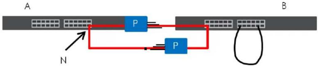
flowchart
graph TD
    A["Gene Array"] -->|N| B["Protein"]
    B --> C["P"]
    C --> D["Protein"]
    D --> E["Protein"]
    E --> F["Protein"]
    F --> G["Protein"]
    G --> H["Protein"]
    H --> I["Protein"]
    I --> J["Protein"]
    J --> K["Protein"]
    K --> L["Protein"]
    L --> M["Protein"]
    M --> N["Protein"]
    N --> O["Protein"]
    O --> P["Protein"]
    P --> Q["Protein"]
    Q --> R["Protein"]
    R --> S["Protein"]
    S --> T["Protein"]
    T --> U["Protein"]
    U --> V["Protein"]
    V --> W["Protein"]
    W --> X["Protein"]
    X --> Y["Protein"]
    Y --> Z["Protein"]
The Switch also shuts down port N if the probe packet returns to switch A on any other port. In other words loop guard also protects against standard network loops. The following figure illustrates three switches forming a loop. A sample path of the loop guard probe packet is also shown. In this example, the probe packet is sent from port N and returns on another port. As long as loop guard is enabled on port N. The Switch will shut down port N if it detects that the probe packet has returned to the Switch.
Figure 108 Loop Guard – Network Loop
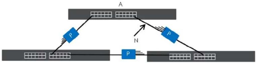
flowchart
graph TD
    A["Layer A"] -->|P| B["Layer B"]
    B -->|N| C["Layer C"]
    C --> D["Layer D"]
    D --> E["Layer E"]
    E --> F["Layer F"]
    F --> G["Layer G"]
    G --> H["Layer H"]
    H --> I["Layer I"]
    I --> J["Layer J"]
    J --> K["Layer K"]
    K --> L["Layer L"]
    L --> M["Layer M"]
    M --> N["Layer N"]
12.1.1 What You Can Do in this Chapter
The Loop Guard screen (Section 12.2 on page 98) displays loop guard status.
12.2 Loop Guard
Use the Loop Guard screen to view Switch loop guard status. Click Monitor > Loop Guard to access this screen.
Figure 109 Monitor > Loop Guard
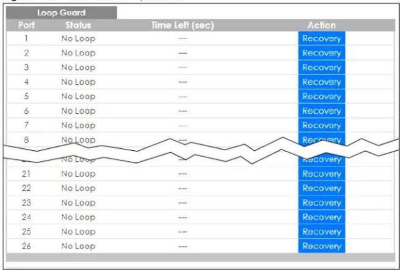
line
Loop Guard | Port | Status | Time Left (sec) | Action | |---|---|---|---| | 1 | No Loop | --- | Recovery | | 2 | No Loop | --- | Recovery | | 3 | No Loop | --- | Recovery | | 4 | No Loop | --- | Recovery | | 5 | No Loop | --- | Recovery | | 6 | No Loop | --- | Recovery | | 7 | No Loop | --- | Recovery | | 8 | No Loop | --- | Recovery | | 9 | No Loop | --- | Recovery | | 21 | No Loop | --- | Recovery | | 22 | No Loop | --- | Recovery | | 23 | No Loop | --- | Recovery | | 24 | No Loop | --- | Recovery | | 25 | No Loop | --- | Recovery | | 26 | No Loop | --- | Recovery |Each field is described in the following table.
Table 43 Monitor > Loop Guard
| LABEL DESCRIPTION | |
| Loop Guard | |
| Port This field displays a port number. | |
| Status This field displays the status. | |
| Time Left (sec) This field displays the amount of time left in seconds. | |
| Action This field displays the action. | |
CHAPTER 13
Monitor: Multicast
13.1 Overview
This section provides information for Multicast in Monitor.
Traditionally, IP packets are transmitted in one of either two ways – Unicast (1 sender to 1 recipient) or Broadcast (1 sender to everybody on the network). Multicast delivers IP packets to just a group of hosts on the network.
IGMP (Internet Group Management Protocol) is a network-layer protocol used to establish membership in an IPv4 multicast group – it is not used to carry user data. Refer to RFC 1112, RFC 2236 and RFC 3376 for information on IGMP versions 1, 2 and 3 respectively.
13.1.1 What You Can Do in this Chapter
The IGMP screen (Section 13.2 on page 100) displays VLAN, statistics, group, and router.
13.2 IGMP Settings
Use this screen to view Switch various multicast features.
13.2.1 VLAN
Use this screen to view the Switch's IGMP VLAN. Click Monitor > Multicast > IGMP > VLAN to access this screen.
Figure 110 Monitor > Multicast > IGMP > VLAN
| IGMP Vlan | VLAN | Statistics | Group | Router | ||||||||
| VLAN ID | Operate Status | Router Ports Auto Learn | Retry | Query Interval | Max. Response Interval | Last Member Query Count | Interval | Status | Querier Version | IP | ||
| 1 | Disable | Enable | 2 | 125 | 10 | 2 | 1 | Non-Querier | --- | --- | ||
Each field is described in the following table.
Table 44 Monitor > Multicast > IGMP > VLAN
| LABEL DESCRIPTION | |
| IGMP Vlan | |
| VLAN ID Displays the identification for the VLAN. | |
| Operate Status Displays the status of the operation. | |
| Router Ports Auto Learn | Displays whether the router ports are auto learn or not. |
| Query | |
| Retry Displays the number of retry. | |
| Interval Displays the number (in seconds) for the time interval. | |
| Max. Response Interval (sec) | Displays the maximum response (in seconds) for the time interval. |
| Last Member Query | |
| Count Displays the number of count. | |
| Interval (sec) Displays the in seconds for the time interval. | |
| Querier | Allows the Switch to send IGMP General Query messages to the VLANs with the multicast hosts attached. |
| Status This field displays the entry as querier or non-querier. | |
| Version This field displays the entry querier version. | |
| IP This field displays the entry querier IP address. | |
| Total Entries This field displays the number of total entries. | |
13.2.2 Statistics
Use this screen to view the Switch's IGMP statistics. Click Monitor > Multicast > IGMP > Statistics to access this screen.
Figure 111 Monitor > Multicast > IGMP > Statistics
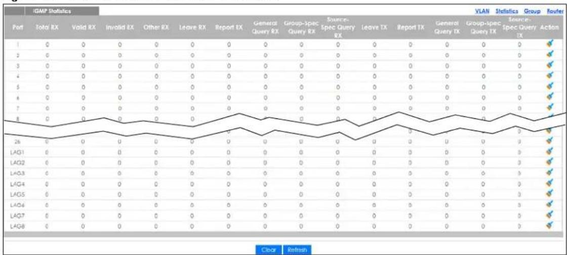
Each field is described in the following table.
Table 45 Monitor > Multicast > IGMP > Statistics
| LABEL DESCRIPTION | |
| IGMP Statistics | |
| Port This field displays a port number. | |
| Total RX This field displays the total amount of RX. | |
| LABEL | DESCRIPTION |
| Valid RX This field displays the total | amount of valid RX. |
| Invalid RX This field displays the total | amount of invalid RX. |
| Other RX This field displays the total | amount of other RX. |
| Leave RX This field displays the total | amount of leave RX. |
| Report RX This field displays the total | amount of report RX. |
| General Query RX This field displays the total | amount of general query RX. |
| Group-Spec Query RX This field displays the total | amount of group-spec query RX. |
| Source-Spec Query RX This field displays the total | amount of source-spec query RX. |
| Leave TX This field displays the total | amount of leave TX. |
| Report TX This field displays the total | amount of report TX. |
| General Query TX This field displays the total | amount of general query TX. |
| Group-Spec Query TX This field displays the total | amount of group-spec query TX. |
| Source-Spec Query TX This field displays the total | amount of source-spec query TX. |
| Action | Click Action to reset the statistics of the specific field back to zero. |
| Clear | Click Clear to clear statistics on this port. |
| Clear | Click Clear to reset the fields to the factory defaults. |
| Refresh | Click Refresh to reload the page. |
In the Action column, the Action option allows you to clear the statistics.
Click OK and confirm at the pop-up screen to complete the task. Click Cancel and confirm at the pop-up screen to discard the changes.
Figure 112 Monitor > Multicast > IGMP > Statistics > Action
13.2.3 Group
Use this screen to view the Switch's IGMP group. Click Monitor > Multicast > IGMP > Group to access this screen.
Figure 113 Monitor > Multicast > IGMP > Group
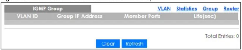
Each field is described in the following table.
Table 46 Monitor > Multicast > IGMP > Group
| LABEL DESCRIPTION | |
| IGMP Group | |
| VLAN ID Displays the identification for the VLAN. | |
| Group IP Address This field displays the group IP address. | |
| Member Ports This field displays the member ports. | |
| Life(sec) Displays life in seconds for the time interval. | |
| Total Entries This field displays the number of total entries. | |
| Clear Click Clear to delete the dynamic groups. | |
| Refresh Click Refresh to reload the page. | |
13.2.4 Router
Use this screen to view the Switch's IGMP router. Click Monitor > Multicast > IGMP > Router to access this screen.
Figure 114 Monitor > Multicast > IGMP > Router

Each field is described in the following table.
Table 47 Monitor > Multicast > IGMP > Router
| LABEL DESCRIPTION | |
| IGMP Router | |
| VLAN ID Displays the identification for the VLAN. | |
| Dynamic Router Ports This field displays the dynamic router ports. | |
| Static Router Ports This field displays the static router ports. | |
| Forbidden Router Ports | This field displays the forbidden router ports. |
| Total Entries This field displays the number of total entries. | |
CHAPTER 14
Monitor: Spanning Tree
14.1 Overview
This section provides information for Spanning Tree in Monitor.
The Switch supports Spanning Tree Protocol (STP), Common and Internal Spanning Tree (CIST), and Multiple Spanning Tree (MST).
14.1.1 What You Can Do in this Chapter
The Spanning Tree screen (Section 14.2 on page 104) displays CIST, CIST port, MST, MST port, STP statistics.
14.2 Spanning Tree
Use this screen to view Switch spanning tree settings.
14.2.1 CIST Settings
Use this screen to view the Switch's spanning tree CIST instance. Click Monitor > Spanning Tree > CIST to access this screen.
Figure 115 Monitor > Spanning Tree > CIST
| CIST Instance | CIST | CIST Port | MST | MST Port | STP Statistics | |
| State | Disable | |||||
| Bridge Identifier | 32768/ 0/4C:9E:FF:72:4A:87 | |||||
| Designated Root Bridge | 0/ 0/00:00:00:00:00:00 | |||||
| External Root Path Cost | 0 | |||||
| Regional Root Bridge | 0/ 0/00:00:00:00:00:00 | |||||
| Internal Root Path Cost | 0 | |||||
| Designated Bridge | 0/ 0/00:00:00:00:00:00 | |||||
| Root Port | 0/0 | |||||
| Remaining Hops | 0 | |||||
| Last Topology Change | 0 | |||||
Each field is described in the following table.
Table 48 Monitor > Spanning Tree > CIST
| LABEL DESCRIPTION | |
| CIST Instance | |
| State This field displays the state. | |
| Bridge Identifier | This is the unique identifier for this bridge, consisting of the bridge priority plus the MAC address. |
| Designated Root Bridge | Root bridge refers to the base of the spanning tree. |
| External Root Path Cost | The cost of the path from this bridge to the CIST Root Bridge. |
| Regional Root Bridge | Root bridge refers to the base of the spanning tree. |
| Internal Root Path Cost | The cost of the path from this bridge to the internal Regional Root Bridge. |
| Designated Bridge | For each LAN segment, a designated bridge is selected. This bridge has the lowest cost to the root among the bridges connected to the LAN. |
| Root Port | On each bridge, the bridge communicates with the root through the root port. The root port is the port on this Switch with the lowest path cost to the root (the root path cost). If there is no root port, then this Switch has been accepted as the root bridge of the spanning tree network. |
| Remaining Hops | This field displays the number of remaining hops. |
| Last Topology Change | Topology change information is directly propagated throughout the network from the device that generates the topology change. |
14.2.2 CIST Port
Use this screen to view the Switch's spanning tree CIST port status. Click Monitor > Spanning Tree > CIST Port to access this screen.
Figure 116 Monitor > Spanning Tree > CIST Port
| CIST Port | CIST | CIST Port | MST | MST Port | STP Stabilis | ||||||||
| Port | Infrastructure (Priority / Port of) | External Path Cost Operation | Internal Path Cost Operation | Designated Root Bridge | External Root Cost | Regional Root Bridge | Internal Root Cost | Designated Bridge | Edge Port Operation | P2F MAC Operation | Port State | Port State | |
| 1 | 128/1 | 20000 | 20000 | 0/00:00:00:00:00:00 | 0 | 0/00:00:00:00:00 | 0 | 0/00:00:00:00:00 | Yes | No | Disagree | Disagree | |
| 2 | 128/2 | 20000 | 20000 | 0/00:00:00:00:00:00 | 0 | 0/00:00:00:00:00 | 0 | 0/00:00:00:00:00 | Yes | No | Disagree | Disagree | |
| 3 | 128/3 | 20000 | 20000 | 0/00:00:00:00:00:00 | 0 | 0/00:00:00:00:00 | 0 | 0/00:00:00:00:00 | Yes | No | Disagree | Disagree | |
| 4 | 128/4 | 20000 | 20000 | 0/00:00:00:00:00:00 | 0 | 0/00:00:00:00:00 | 0 | 0/00:00:00:00:00 | Yes | No | Disagree | Disagree | |
| 5 | 128/5 | 20000 | 20000 | 0/00:00:00:00:00:00 | 0 | 0/00:00:00:00:00 | 0 | 0/00:00:00:00:00 | Yes | No | Disagree | Disagree | |
| 6 | 128/6 | 20000 | 20000 | 0/00:00:00:00:00:00 | 0 | 0/00:00:00:00:00 | 0 | 0/00:00:00:00:00 | Yes | No | Disagree | Disagree | |
| 7 | 128/7 | 20000 | 20000 | 0/00:00:00:00:00:00 | 0 | 0/00:00:00:00:00 | 0 | 0/00:00:00:00:00 | Yes | No | Disagree | Disagree | |
| 8 | 128/8 | 20000 | 20000 | 0/00:00:00:00:00:00 | 0 | 0/00:00:00:00:00 | 0 | 0/00:00:00:00:00 | Yes | No | Disagree | Disagree | |
| 9 | 128/9 | 20000 | 20000 | 0/00:00:00:00:00:00 | 0 | 0/00:00:00:00:00 | 0 | 0/00:00:00:00:00 | Yes | No | Disagree | Disagree | |
| 10 | 128/10 | 20000 | 20000 | 0/00:00:00:00:00:00 | 0 | 0/00:00:00:00:00 | 0 | 0/00:00:00:00:00 | Yes | No | Disagree | Disagree | |
| 11 | 128/11 | 20000 | 20000 | 0/00:00:00:00:00:00 | 0 | 0/00:00:00:00:00 | 0 | 0/00:00:00:00:00 | Yes | No | Disagree | Disagree | |
| 12 | 128/12 | 20000 | 20000 | 0/00:00:00:00:00:00 | 0 | 0/00:00:00:00:00 | 0 | 0/00:00:00:00:00 | Yes | No | Disagree | Disagree | |
| LAQ1 | 128/127 | 20000 | 20000 | 0/00:00:00:00:00:00 | 0 | 0/00:00:00:00:00 | 0 | 0/00:00:00:00:00 | Yes | No | Disagree | Disagree | |
| LAQ2 | 128/128 | 20000 | 20000 | 0/00:00:00:00:00:00 | 0 | 0/00:00:00:00:00 | 0 | 0/00:00:00:00:00 | Yes | No | Disagree | Disagree | |
| LAQ3 | 128/129 | 20000 | 20000 | 0/00:00:00:00:00:00 | 0 | 0/00:00:00:00:00 | 0 | 0/00:00:00:00:00 | Yes | No | Disagree | Disagree | |
| LAQ4 | 128/130 | 20000 | 20000 | 0/00:00:00:00:00:00 | 0 | 0/00:00:00:00:00 | 0 | 0/00:00:00:00:00 | Yes | No | Disagree | Disagree | |
| LAQ5 | 128/131 | 20000 | 20000 | 0/00:00:00:00:00:00 | 0 | 0/00:00:00:00:00 | 0 | 0/00:00:00:00:00 | Yes | No | Disagree | Disagree | |
| LAQ6 | 128/132 | 20000 | 20000 | 0/00:00:00:00:00:00 | 0 | 0/00:00:00:00:00 | 0 | 0/00:00:00:00:00 | Yes | No | Disagree | Disagree | |
| LAQ7 | 128/133 | 20000 | 20000 | 0/00:00:00:00:00:00 | 0 | 0/00:00:00:00:00 | 0 | 0/00:00:00:00:00 | Yes | No | Disagree | Disagree | |
| LAQ8 | 128/134 | 20000 | 20000 | 0/00:00:00:00:00:00 | 0 | 0/00:00:00:00:00 | 0 | 0/00:00:00:00:00 | Yes | No | Disagree | Disagree | |
Each field is described in the following table.
Table 49 Monitor > Spanning Tree > CIST Port
| LABEL DESCRIPTION | |
| Port This field displays the port number. | |
| Identifier (Priority / Port Id) | This field displays the identifier (in priority / port number). |
| External Path Cost Operation | Path cost is the cost of transmitting a frame on to a LAN through that port. It is recommended to assign this value according to the speed of the bridge. The slower the media, the higher the cost. |
| LABEL DESCRIPTION | |
| Internal Path Cost Operation | Path cost is the cost of transmitting a frame on to a LAN through that port. It is recommended to assign this value according to the speed of the bridge. The slower the media, the higher the cost. |
| Designated Root Bridge | Root bridge refers to the base of the spanning tree. |
| External Root Cost This field displays the external root cost. | |
| Regional Root Bridge | Root bridge refers to the base of the spanning tree. |
| Internal Root Cost This field displays the internal root cost. | |
| Designated Bridge | For each LAN segment, a designated bridge is selected. This bridge has the lowest cost to the root among the bridges connected to the LAN. |
| Edge Port Operation | An edge port changes its initial STP port state from blocking state to forwarding state immediately without going through listening and learning states right after the port is configured as an edge port or when its link status changes. |
| P2P MAC Operation | This field displays the state of the P2P MAC operation. |
| Port Role This field displays the state of the port role. | |
| Port State This field displays the state of the port. | |
14.2.3 MST Settings
Use this screen to view the Switch's spanning tree MST instance. Click Monitor > Spanning Tree > MST to access this screen.
Figure 117 Monitor > Spanning Tree > MST
| MST Instance | CIST | CIST Port | MST | MST Port | STP Statistics | |
| MST ID | 1 | |||||
| State | Disable | |||||
| Regional Root Bridge | ---/--- | |||||
| Internal Root Cost | --- | |||||
| Designated Bridge | --/-- | |||||
| Root Port | ---/--- | |||||
| Remaining Hops | ---/--- | |||||
| Last Topology Change | ---/--- | |||||
Each field is described in the following table.
Table 50 Monitor > Spanning Tree > MST
| LABEL DESCRIPTION | |
| MST Instance | |
| MST ID This is the unique identifier for this MST.Select a number from the drop-down menu to display results. | |
| State This field displays the state. | |
| Regional Root Bridge Root bridge refers to the base of the spanning tree. | |
| Internal Root Cost This field displays the internal root cost. | |
| Designated Bridge | For each LAN segment, a designated bridge is selected. This bridge has the lowest cost to the root among the bridges connected to the LAN. |
| Root Port | On each bridge, the bridge communicates with the root through the root port. The root port is the port on this Switch with the lowest path cost to the root (the root path cost). If there is no root port, then this Switch has been accepted as the root bridge of the spanning tree network. |
| Remaining Hops This field displays the number of remaining hops. | |
| Last Topology Change | Topology change information is directly propagated throughout the network from the device that generates the topology change. |
14.2.4 MST Port
Use this screen to view the Switch's spanning tree MST port status. Click Monitor > Spanning Tree > MST Port to access this screen.
Figure 118 Monitor > Spanning Tree > MST Port
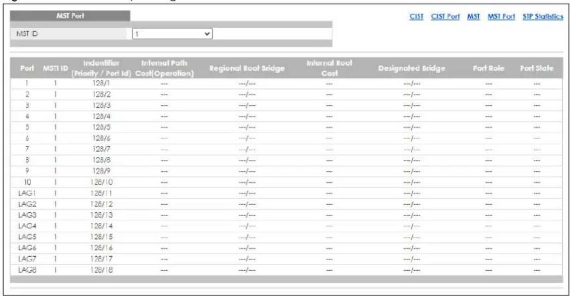
Each field is described in the following table.
Table 51 Monitor > Spanning Tree > MST Port
| LABEL DESCRIPTION | |
| MST Port | |
| MST ID This is the unique | e identifier for this MST.Select a number from the drop-down menu to display results. |
| Port This field displays | the port number. |
| MSTI ID | A VLAN can be mapped to a specific Multiple Spanning Tree Instance (MSTI). MSTI allows multiple VLANs to use the same spanning tree. |
| Identifier (Priority / Port Id) | This field displays the identifier (in priority / port number). |
| Internal Path Cost(Operation) | Path cost is the cost of transmitting a frame on to a LAN through that port. It is recommended to assign this value according to the speed of the bridge. The slower the media, the higher the cost. |
| Regional Root Bridge | Root bridge refers to the base of the spanning tree. |
| Internal Root Cost This | field displays the internal root cost. |
| Designated Bridge | For each LAN segment, a designated bridge is selected. This bridge has the lowest cost to the root among the bridges connected to the LAN. |
| Port Role This field displays the state of the port role. | |
| Port State This field displays the state of the port. | |
14.2.5 STP Statistics
(R)STP detects and breaks network loops and provides backup links between switches, bridges or routers. It allows a Switch to interact with other (R)STP-compliant switches in your network to ensure that only one path exists between any two stations on the network.
The Switch uses IEEE 802.1w RSTP (Rapid Spanning Tree Protocol) that allows faster convergence of the spanning tree than STP (while also being backwards compatible with STP-only aware bridges). In RSTP, topology change information is directly propagated throughout the network from the device that generates the topology change. In STP, a longer delay is required as the device that causes a topology change first notifies the root bridge and then the root bridge notifies the network. Both RSTP and STP flush unwanted learned addresses from the filtering database. In RSTP, the port states are Discarding, Learning, and Forwarding.
Note: In this user's guide, "STP" refers to both STP and RSTP.
Use this screen to view the Switch's spanning tree STP statistics. Click Monitor > Spanning Tree > STP Statistics to access this screen.
Figure 119 Monitor > Spanning Tree > STP Statistics
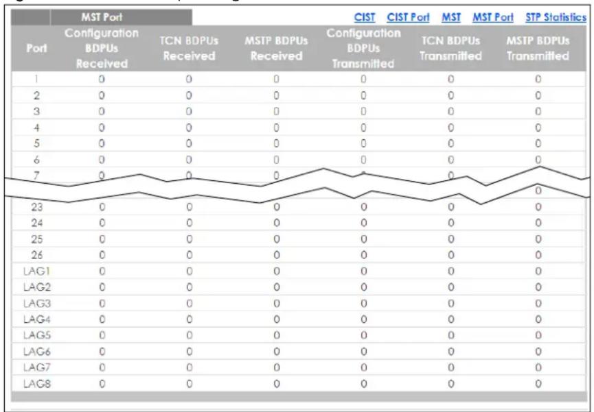
line
| Port | MST Port Configuration BDPUs Received | MSTP BDPUs Received | CIST Configuration BDPUs Transmitted | CIST Port TCN BDPUs Transmitted | MST MST Port MST BDPUs Transmitted | MST PMST Statistics MST BDPUs Transmitted | |---|---|---|---|---|---|---| | 1 | 0 | 0 | 0 | 0 | 0 | 0 | | 2 | 0 | 0 | 0 | 0 | 0 | 0 | | 3 | 0 | 0 | 0 | 0 | 0 | 0 | | 4 | 0 | 0 | 0 | 0 | 0 | 0 | | 5 | 0 | 0 | 0 | 0 | 0 | 0 | | 6 | 0 | 0 | 0 | 0 | 0 | 0 | | 7 | 0 | 0 | 0 | 0 | 0 | 0 | | 23 | 0 | 0 | 0 | 0 | 0 | 0 | | 24 | 0 | 0 | 0 | 0 | 0 | 0 | | 25 | 0 | 0 | 0 | 0 | 0 | 0 | | 26 | 0 | 0 | 0 | 0 | 0 | 0 | | LAG1 | 0 | 0 | 0 | 0 | 0 | 0 | | LAG2 | 0 | 0 | 0 | 0 | 0 | 0 | | LAG3 | 0 | 0 | 0 | 0 | 0 | 0 | | LAG4 | 0 | 0 | 0 | 0 | 0 | 0 | | LAG5 | 0 | 0 | 0 | 0 | 0 | 0 | | LAG6 | 0 | 0 | 0 | 0 | 0 | 0 | | LAG7 | 0 | 0 | 0 | 0 | 0 | 0 | | LAG8 | 0 | 0 | 0 | 0 | 0 | 0 | The chart displays a line graph with values for each port configuration. The x-axis represents port numbers (1 to 8), and the y-axis represents the count of received or transmitted units. The legend indicates that 'CIST Port' and 'STP Statistics' are labeled above the chart.Each field is described in the following table.
Table 52 Monitor > Spanning Tree > STP Statistics
| LABEL DESCRIPTION | |
| MST Port | |
| Port This field displays the port number. | |
| Configuration BDPUs Received | This field displays the configuration BDPUs received. |
| TCN BDPUs Received | This field displays the TCN BDPUs received. |
| MSTP BDPUs Received | This field displays the Multiple Spanning Tree Protocol (MSTP) BDPUs received. |
| Configuration BDPUs Transmitted | This field displays the configuration BDPUs transmitted. |
| TCN BDPUs Transmitted | This field displays the TCN BDPUs transmitted. |
| MSTP BDPUs Transmitted | This field displays the Multiple Spanning Tree Protocol (MSTP) BDPUs transmitted. |
CHAPTER 15
Monitor: LLDP
15.1 Overview
This section provides information for LLDP in Monitor.
Link Layer Discovery Protocol (LLDP), defined as IEEE 802.1ab, enables LAN devices that support LLDP to exchange their configured settings. This helps eliminate configuration mismatch issues.
15.1.1 What You Can Do in this Chapter
The LLDP screen (Section 15.2 on page 110) displays statistics, remote information, and overloading.
15.2 LLDP Settings
This link takes you to a screen where you can view LLDP on the Switch. LLDP allows a network device to advertise its identity and capabilities on the local network. It also allows the device to maintain and store information from adjacent devices which are directly connected to the network device.
15.2.1 Statistics Settings
Use this screen to view the Switch's LLDP global and port statistics. Click Monitor > LLDP > Statistics to access this screen.
Figure 120 Monitor > LLDP > Statistics
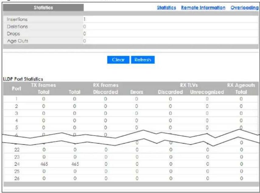
other
Statistics Statistics Remote Information Overloading | Port | TX Frames Total | TX Frames Total | RX Frames Discarded | RX Frames Errors | RX TLVs Discarded | RX TLVs Unrecognized | RX Ageouts Total | |---|---|---|---|---|---|---|---| | 1 | 0 | 0 | 0 | 0 | 0 | 0 | 0 | | 2 | 0 | 0 | 0 | 0 | 0 | 0 | 0 | | 3 | 0 | 0 | 0 | 0 | 0 | 0 | 0 | | 4 | 0 | 0 | 0 | 0 | 0 | 0 | 0 | | 5 | 0 | 0 | 0 | 0 | 0 | 0 | 0 | | 6 | 0 | 0 | 0 | 0 | 0 | 0 | 0 | | 22 | 0 | 0 | 0 | 0 | 0 | 0 | 0 | | 23 | 0 | 0 | 0 | 0 | 0 | 0 | 0 | | 24 | 465 | 465 | 0 | 0 | 0 | 0 | 0 | | 25 | 0 | 0 | 0 | 0 | 0 | 0 | 0 | | 26 | 0 | 0 | 0 | 0 | 0 | 0 | 0 | Clear Refresh LLDP Port Statistics Port: TX Frames Total RX Frames Discarded Errors Discarded Unrecognized TotalEach field is described in the following table.
Table 53 Monitor > LLDP > Statistics
| LABEL DESCRIPTION | |
| Statistics | |
| Insertions This field displays the number of insertions. | |
| Deletions This field displays the number of deletions. | |
| Drops This field displays the number of drops. | |
| Age Outs This field displays the number of age outs. | |
| Clear Click Clear to clear statistics. | |
| Refresh Click Refresh to reload the page. | |
| LLDP Port Statistics | |
| Port This field displays the port number. | |
| TX Frames Total This field displays the total number of TX LLDP frames. | |
| RX Frames Total This field displays the total number of RX LLDP frames. | |
| RX Frames Discarded This field displays the number of discarded RX LLDP frames. | |
| RX Frames Errors This field displays the number of RX LLDP frames errors. | |
| RX TLVs Discarded This field displays the number of discarded RX LLDP TLVs. | |
| RX TLVs Unrecognized This field displays the number of unrecognized RX LLDP TLVs. | |
| RX Ageouts Total This field displays the total number of RX LLDP ageouts. | |
15.2.2 Remote Information
Use this screen to view the Switch's LLDP remote device information. Click Monitor > LLDP > Remote Information to access this screen.
Figure 121 Monitor > LLDP > Remote Information
| Remote Device | Statistics | Remote Information | Overloading | ||||
| Local Port | Chassis ID Subtype | Chassis ID | Port ID Subtype | Port ID | System Name | Time to Live | Action |
| 24 | MAC address | E4:18:68:F7:8 A:79 | Locally assigned | 18 | 11A01_64 | 95 | |
Each field is described in the following table.
Table 54 Monitor > LLDP > Remote Information
| LABEL DESCRIPTION | |
| Remote Device | |
| Local Port This field displays the local port. | |
| Chassis ID Subtype This field displays the chassis ID subtype. | |
| Chassis ID This field displays the chassis ID. | |
| Port ID Subtype This field displays the port ID subtype. | |
| Port ID This field displays the port ID. | |
| System Name | This field displays the descriptive name of the Switch for identification purposes. |
| Time to Live This field displays the live time of this entry. | |
| Action | |
| Detail | Click Detail to show more information about this entry. |
| Delete Click Delete | to remove the entry. |
15.2.3 Overloading
Use this screen to view the Switch's LLDP port overloading. Click Monitor > LLDP > Overloading to access this screen.
Figure 122 Monitor > LLDP > Overloading
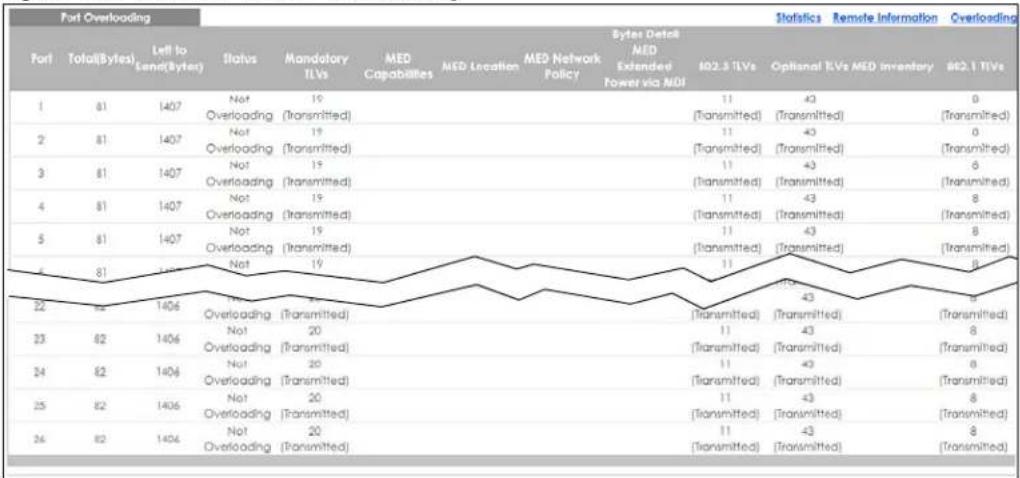
line
Port Overloading Statistics Remote Information Overloading Port Total(Bytes) Left to Land(Bytes) Status Mandatory MED Capabilities MED Location MED Network Policy Bytes Detail MED Extended Power via NDI 102.3 TLVs Optional TLVs MED Inventory #2.1 TLVs | Port | Total(Bytes) | Left to Land(Bytes) | StatusEach field is described in the following table.
Table 55 Monitor > LLDP > Overloading
| LABEL DESCRIPTION | |
| Port Overloading | |
| Port This label shows the port you are viewing. | |
| Total (Bytes) This field displays the total in bytes. | |
| Left to Send (Bytes) This field displays what is left to send in bytes. | |
| Status This field displays whether the Switch is overloading or not. | |
| Bytes Detail This field displays how many bytes used by TLVs | |
| Mandatory TLVs This field displays how many bytes used by mandatory TLVs. | |
| MED Capabilities This field displays how many bytes used by MED capabilities. | |
| MED Location This field displays how many bytes used by MED location. | |
| MED Network Policy | This field displays how many bytes used by MED network policy. |
| MED Extended Power via MDI | This field displays how many bytes used by MED extended power through MDI. |
| 802.3 TLVs This field displays how many bytes used by 802.3 TLVs. | |
| Optional TLVs This field displays how many bytes used by optional TLVs. | |
| MED Inventory This field displays how many bytes used by MED inventory. | |
| 802.1 TLVs This field displays how many bytes used by 802.1 TLVs. | |
CHAPTER 16
Monitor: Security
16.1 Overview
This section provides information for Security in Monitor.
This link takes you to a screen where you can view the settings or traffic statistics which contain detailed information about specific activities.
16.1.1 What You Can Do in this Chapter
- The Port Security screen (Section 16.2 on page 114) displays global and port.
- The 802.1X screen (Section 16.3 on page 115) displays port and authenticated hosts.
16.2 Port Security
Port security allows only packets with dynamically learned MAC addresses and/or configured static MAC addresses to pass through a port on the Switch. The Switch can learn up to 8K MAC addresses in total with no limit on individual ports; system total MAC address entry is 8K. Static MAC address still can be configured when port security is enabled; the function of port security is concerned with dynamic MAC address learn action. When total MAC address entry is 8k, static MAC can not be configured.
Use this screen to view Switch port security settings. Click Monitor > Security > Port Security to access this screen.
Figure 123 Monitor > Security > Port Security
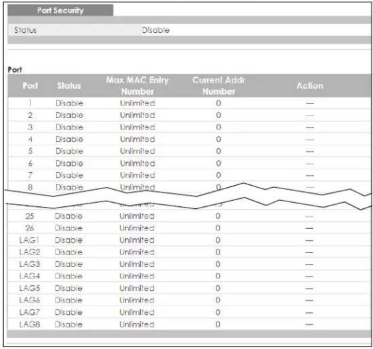
other
Port Security Status Disable Port Port Status Max MAC Entry Number Current Addr Number Action 1 Disable Unlimited 0 --- 2 Disable Unlimited 0 --- 3 Disable Unlimited 0 --- 4 Disable Unlimited 0 --- 5 Disable Unlimited 0 --- 6 Disable Unlimited 0 --- 7 Disable Unlimited 0 --- 8 Disable Unlimited 0 --- 25 Disable Unlimited 0 --- 26 Disable Unlimited 0 --- LAG1 Disable Unlimited 0 --- LAG2 Disable Unlimited 0 --- LAG3 Disable Unlimited 0 --- LAG4 Disable Unlimited 0 --- LAG5 Disable Unlimited 0 --- LAG6 Disable Unlimited 0 --- LAG7 Disable Unlimited 0 --- LAG8 Disable Unlimited 0 --- Max MAC Entry Number Current Addr Number ActionEach field is described in the following table.
Table 56 Monitor > Security > Port Security
| LABEL DESCRIPTION | |
| Port Security | |
| Status This field displays the status of global control information. | |
| Port | |
| Port This field displays a port number. | |
| Status This field displays the status of port based control information. | |
| Max MAC Entry Number | Displays the designated maximum number of allowed MAC entries. The maximum MAC entry number can be learned for individual ports. |
| Current Addr Number | This field displays the number of the current addr. |
| Action | This field displays the actions the Switch takes on the associated classified traffic flow. |
16.3 802.1X Security Settings
Use this screen to view Switch 802.1x security settings.
16.3.1 Port Settings
Use this screen to view the Switch's 802.1x port status. Click Monitor > Security > 802.1X > Port to access this screen.
Figure 124 Monitor > Security > 802.1X > Port
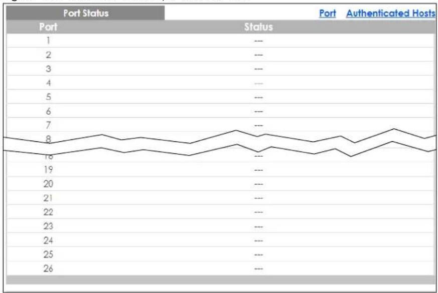
line
| Port | Status | | ---- | ------ | | 1 | --- | | 2 | --- | | 3 | --- | | 4 | --- | | 5 | --- | | 6 | --- | | 7 | --- | | 8 | --- | | 9 | --- | | 10 | --- | | 11 | --- | | 12 | --- | | 13 | --- | | 14 | --- | | 15 | --- | | 16 | --- | | 17 | --- | | 18 | --- | | 19 | --- | | 20 | --- | | 21 | --- | | 22 | --- | | 23 | --- | | 24 | --- | | 25 | --- | | 26 | --- |Each field is described in the following table.
Table 57 Monitor > Security > 802.1X > Port
| LABEL DESCRIPTION | |
| Port Status | |
| Port This label shows the port you are viewing. | |
| Status This field displays status of the port. | |
16.3.2 Authenticated Hosts
Use this screen to view the Switch's 802.1x security authenticated host status. Click Monitor > Security > 802.1X > Authenticated Hosts to access this screen.
Figure 125 Monitor > Security > 802.1X > Authenticated Hosts

flowchart
graph LR
    A["Authenticated Hosts"] --> B["User Name"]
    A --> C["Port"]
    A --> D["Session Time"]
    D --> E["Authentication Method"]
    E --> F["MAC Address"]
    G["Port"] --> H["Authenticated Hosts"]
Each field is described in the following table.
Table 58 Monitor > Security > 802.1X > Authenticated Hosts
| LABEL DESCRIPTION | |
| Authenticated Hosts | |
| User Name This field displays the name of a user. | |
| Port This label shows the port you are viewing. | |
| Session Time This label shows the session time. | |
| Authentication Method | This label shows the authentication method. |
| MAC Address This field displays the source MAC address in the binding. | |
CHAPTER 17
Monitor: Management
17.1 Overview
This section provides information for Management in Monitor.
This chapter describes how to view management settings on the Switch.
17.1.1 What You Can Do in this Chapter
- The Syslog screen (Section 17.2 on page 117) displays logging filter select and shows system log.
- The Error Disable screen (Section 17.3 on page 118) displays global and port.
17.2 Syslog
Use this screen to view Switch syslog management. Click Monitor > Management > Syslog to access this screen.
Figure 126 Monitor > Management > Syslog
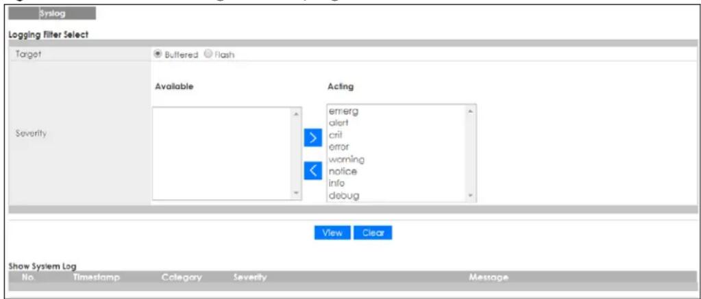
Each field is described in the following table.
Table 59 Monitor > Management > Syslog
| LABEL DESCRIPTION | ||
| Logging Filter Select | ||
| Target | SelectBufferedor Flash.Buffered: Login saved to temporary memory.Flash: Login saved to permanent memory. | |
| Severity This field displays two options: Available and Acting. | ||
| Severity type: crit, emerg, alert, error, warning, notice, info, and debug. | ||
| Available | Click < to move a severity type from the acting box to the available box.Click > to move a severity type to the acting box from the available box. | |
| Acting | Click < to move a severity type from the acting box to the available box.Click > to move a severity type to the acting box from the available box. | |
| > | Click > to move a severity type to the acting box from the available box. | |
| < | Click < to move a severity type from the acting box to the available box. | |
| View | Click View to display results. | |
| Clear | Click Clear to clear results. | |
| Show System Log | The syslog protocol allows devices to send event notification messages across an IP network to syslog servers that collect the event messages. A syslog-enabled device can generate a syslog message and send it to a syslog server | |
| No. This field displays the number you are viewing. | ||
| Timestamp This field displays the timestamp. | ||
| Category This field displays the category. | ||
| Severity This field displays the severity. | ||
| Message | The syslog protocol allows devices to send event notification messages across an IP network to syslog servers that collect the event messages. A syslog-enabled device can generate a syslog message and send it to a syslog server. | |
17.3 Error Disable
This link takes you to a screen where you can view CPU protection and error disable recovery.
Use this screen to view Switch global and port error disable management. Click Monitor > Management > Error Disable to access this screen.
Figure 127 Monitor > Management > Error Disable
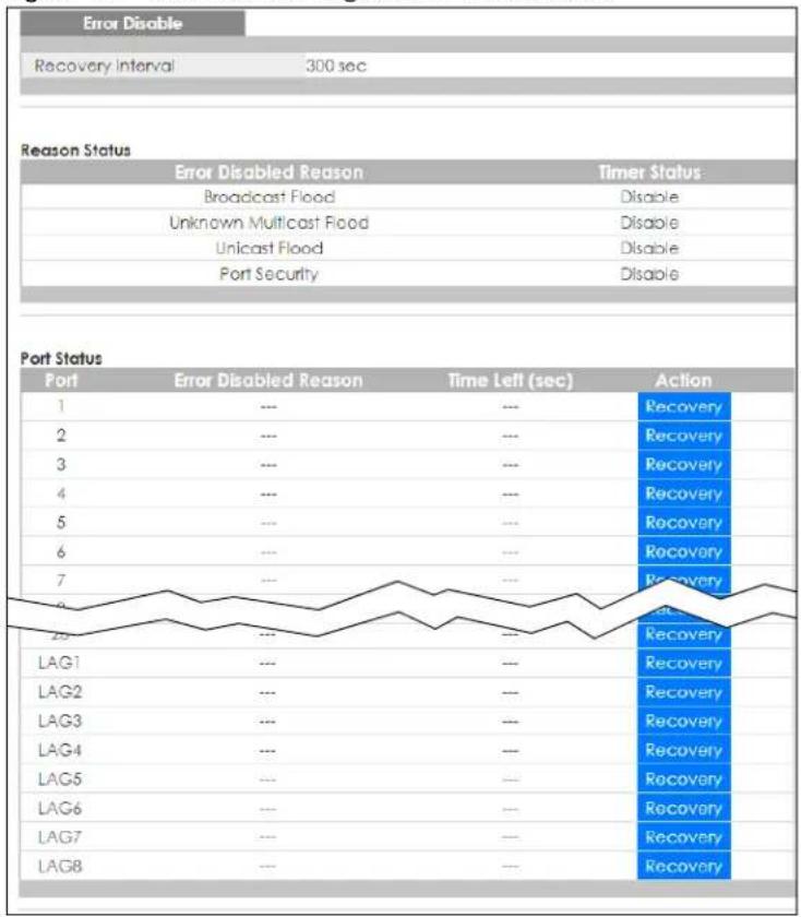
Each field is described in the following table.
Table 60 Monitor > Management > Error Disable
| LABEL DESCRIPTION | |
| Error Disable | |
| Recovery Interval | View the number of seconds (from 30 to 2592000) for the time interval of the recovery. |
| Reason Status | |
| Error Disabled Reason | This field displays the supported features that allow the Switch to shut down a port or discard packets on a port according to the feature requirements and what action you configure. |
| Timer Status | Select this option to allow the Switch to wait for the specified time interval to activate a port or allow specific packets on a port, after the error was gone. De-select this option to turn off this rule. |
| Port Status | |
| Port This field displays the port number. | |
| Error Disabled Reason | This field displays the supported features that allow the Switch to shut down a port or discard packets on a port according to the feature requirements and what action you configure. |
| Time Left (sec) This | field displays the time left in seconds. |
| Action This field displays the action. | |
CHAPTER 18
Configuration: System
18.1 Overview
This section provides information for System in Configuration.
18.1.1 What You Can Do in this Chapter
- The IP screen (Section 18.2 on page 120) displays IPv4 and IPv6 settings.
- The Time screen (Section 18.3 on page 122) displays the system time and SNTP settings.
- The Information screen (Section 18.4 on page 123) displays the system information.
18.2 IP Settings
The Switch needs an IP address for it to be managed over the network. The factory default IP address is 192.168.1.1. The subnet mask specifies the network number portion of an IP address. The factory default subnet mask is 255.255.255.0.
18.2.1 IPv4 Settings
Use this screen to view the IPv4 interface status and Switch's management IPv4 addresses. Click Configuration > System > IP > IPv4 to open this screen.
Figure 128 Configuration > System > IP > IPv4
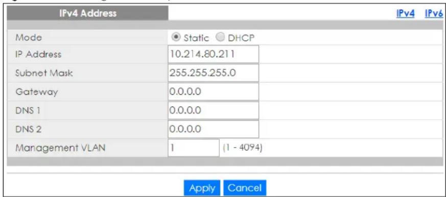
The following table describes the labels in this screen.
Table 61 Configuration > System > IP > IPv4
| LABEL DESCRIPTION | |
| IPv4 Address | |
| Mode | Select Static to define the IPv4 network properties or DHCP to allow the device to define the properties. |
| IP Address Enter the IP address of the Switch in the IP domain. | |
| Subnet Mask | Enter the subnet mask of the Switch in the IP domain. |
| Gateway Enter the IP address of the default outgoing gateway in dotted decimal notation, for example 192.168.1.254. | |
| DNS 1 Enter the IP address for the primary domain name server. DNS (Domain Name System) is for mapping a domain name to its corresponding IP address and vice versa. | |
| DNS 2 Enter the IP address for the secondary domain name server. DNS (Domain Name System) is for mapping a domain name to its corresponding IP address and vice versa. | |
| Management VLAN | Enter the port number of the management VLAN. |
| Apply | Click Apply to save the changes. |
| Cancel | Click Cancel to discard the changes. |
18.2.2 IPv6 Settings
Use this screen to view the IPv6 interface status and Switch's management IPv6 addresses.
Click Configuration > System > IP > IPv6 to open this screen.
Figure 129 Configuration > System > IP > IPv6
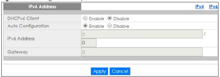
The following table describes the labels in this screen.
Table 62 Configuration > System > IP > IPv6
| LABEL DESCRIPTION | |
| IPv6 Address | |
| DHCPv6 Client | Select Enable to allow the device to act as a DHCPv6 client or Disable to disallow it. This field displays the Switch's DHCP settings when it is acting as a DHCPv6 client. |
| Auto Configuration | Select Enable to allow the device to auto-configure the IPv6 properties or Disable to manually enter the properties. |
| IPv6 Address | Enter the IPv6 address of the Switch in the IP domain. |
| Gateway | Enter the IPv6 address of the default outgoing gateway. |
| Apply | Click Apply to save the changes. |
| Cancel | Click Cancel to discard the changes. |
18.3 Time
The Time option is used to setup the system time and SNTP (Simple Network Time Protocol) server settings.
18.3.1 System Time Settings
In the navigation panel, click Configuration > System > Time > System Time to display the screen as shown.
Figure 130 Configuration > System > Time > System Time
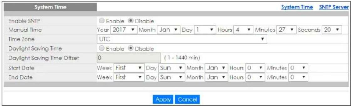
The following table describes the labels in this screen.
Table 63 Configuration > System > Time > System Time
| LABEL DESCRIPTION | |
| System Time | |
| Enable SNTP | Select Enable to enable using a simple network time protocol (SNTP) server to manage the system time or Disable to manually manage system time. |
| Manual Time | Select the system date and time values from the dropdown lists. |
| Time Zone Select the time zone from the dropdown list. | |
| Daylight Saving Time | Select Enable to use Daylight Saving Time to offset the system time or Disable to not adjust system time. |
| Daylight Saving Time Offset | Enter the daylight saving time offset value in minutes. |
| Start Date | Select the start date of the daylight saving time period from the dropdown lists. |
| End Date Select the end date of the daylight saving time period from the dropdown lists. | |
| Apply | Click Apply to save the changes. |
| Cancel | Click Cancel to discard the changes. |
18.3.2 SNTP Server Settings
In the navigation panel, click Configuration > System > Time > SNTP Server to display the screen as shown.
Figure 131 Configuration > System > Time > SNTP Server
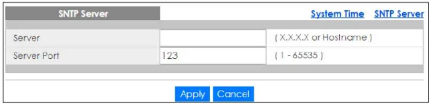
The following table describes the labels in this screen.
Table 64 Configuration > System > Time > SNTP Server
| LABEL DESCRIPTION | |
| SNTP Server | |
| Server | Enter the address of the simple network time protocol (SNTP) server as an IP address (192.168.0.1) or as a URL (www.zyxel.com). |
| Server Port | Enter the port number of the SNTP server. The numeric value can be between 1 and 65535. |
| Apply | Click Apply to save the changes. |
| Cancel | Click Cancel to discard the changes. |
18.4 Information
The information option is used to set the following system information properties: system name, system location, and system contact information.
18.4.1 System Information Settings
In the navigation panel, click Configuration > System > Information > System Information to display the screen as shown. You can set the system name, system location, and system contact.
Figure 132 Configuration > System > Information > System Information
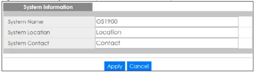
The following table describes the labels in this screen.
Table 65 Configuration > System > Information > System Information
| LABEL DESCRIPTION | |
| System Information | |
| System Name | Enter the descriptive name of the Switch for identification purposes. |
| System Location | Enter the geographic location of the Switch for identification purposes. |
| System Contact Enter | the person in charge of the Switch for identification purposes. |
| Apply | Click Apply to save the changes. |
| Cancel | Click Cancel to discard the changes. |
CHAPTER 19
Configuration: Port
19.1 Overview
This section provides information for Port in Configuration.
19.1.1 What You Can Do in this Chapter
- The Port screen (Section 19.2 on page 125) displays general port settings.
- The EEE screen (Section 19.3 on page 127) displays the port EEE settings.
- The PoE screen (Section 19.4 on page 129) displays the port PoE settings.
- The Bandwidth Management screen (Section 19.5 on page 134) displays the port ingress and egress settings.
- The Storm Control screen (Section 19.6 on page 135) displays the port storm control settings.
19.2 Port Settings
Use this screen to view and edit general port settings.
19.2.1 Port
Use this screen to view Switch port settings and select ports for configuration. Click Configuration > Port > Port to open this screen.
Figure 133 Configuration > Port > Port
| Port | ||||||
| Port | Port Name | State | Link Status | Speed | Duplex | FlowCtrl State |
| 1 | Enable | Down | Auto | Auto | Disable | |
| 2 | Enable | Down | Auto | Auto | Disable | |
| 3 | Enable | Down | Auto | Auto | Disable | |
| 4 | Enable | Down | Auto | Auto | Disable | |
| 5 | Enable | Down | Auto | Auto | Disable | |
| 6 | Enable | Down | Auto | Auto | Disable | |
| 7 | Enable | Down | Auto | Auto | Disable | |
| 8 | Enable | Down | Auto | Auto | Disable | |
| 9 | Enable | Down | Auto | Auto | Disable | |
| 10 | ||||||
| 11 | ||||||
| 12 | Enable | Down | Auto | Auto | Disable | |
| 23 | Enable | Down | Auto | Auto | Disable | |
| 24 | Enable | Up | Auto | Auto | Disable | |
| 25 | Enable | Down | Auto | Auto | Disable | |
| 26 | Enable | Down | Auto | Auto | Disable | |
The following table describes the labels in this screen.
Table 66 Configuration > Port > Port
| LABEL DESCRIPTION | |
| Port | |
| Port Displays the port index number. | |
| Port Name | Displays a descriptive name that identifies this port. The length of the name can be up to 32 alpha-numerical characters.Note: Due to space limitations, the port name may be truncated in some Web Configurator screens. |
| State Displays the port status as enabled or disabled. | |
| Link Status Displays the link status as up or down. | |
| Speed | Displays the speed of the Ethernet connection on this port. The choices areAuto, 10M, 100M, and1000M. |
| Duplex | Displays the duplex mode of the Ethernet connection on this port. The choices areauto, full, or half. |
| FlowCtrl State | Displays the flow control state as enabled or disabled. A concentration of traffic on a port decreases port bandwidth and overflows buffer memory causing packet discards and frame losses. Flow Control is used to regulate transmission of signals to match the bandwidth of the receiving port. |
| Edit | Select this check box to configure the properties of a port. Click theEditbutton change the properties of the port. |
| Cancel | Click Cancelto discard the changes. |
19.2.2 Port Edit
Use this screen to configure Switch port settings. Click Configuration > Port > Port > Edit to open this screen.
Figure 134 Configuration > Port > Port > Edit
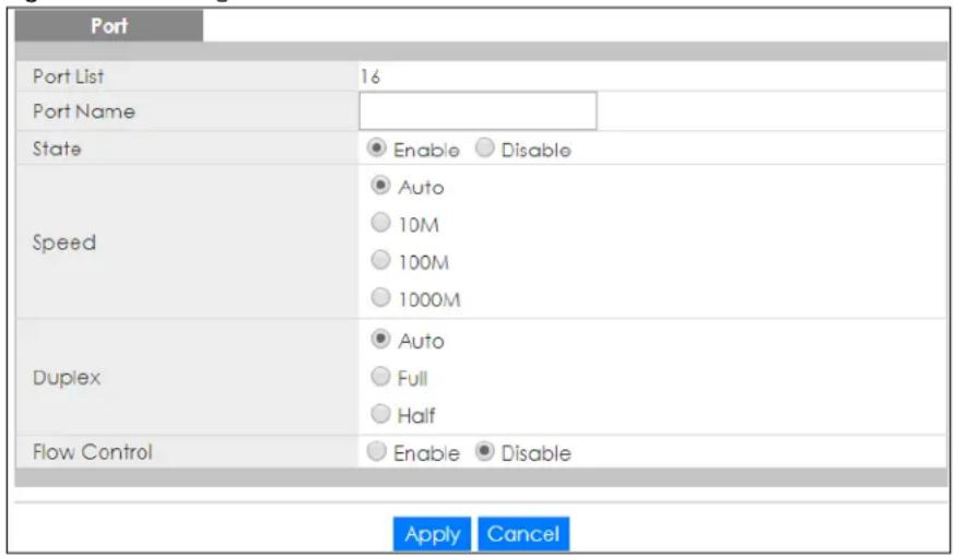
The following table describes the labels in this screen.
Table 67 Configuration > Port > Port > Edit
| LABEL DESCRIPTION | |
| Port | |
| Port List | Displays the list of port index numbers that are being configured. |
| Port Name | Enter a descriptive name that identifies this port. The length of the name can be up to 32 alpha-numerical characters.Note: Due to space limitations, the port name may be truncated in some Web Configurator screens. |
| State | Select Enable to enable the ports or Disable to disable them. |
| Speed | Select the speed of the Ethernet connection on this port. The choices are Auto, 10M, 100M, and 1000M. |
| Duplex | Select the duplex mode of the Ethernet connection on this port. The choices are Auto, Full, or Half. |
| FlowCtrl State | Select Enable to allow the device to manage data flow or Disable to have no data flow management. A concentration of traffic on a port decreases port bandwidth and overflows buffer memory causing packet discards and frame losses. Flow Control is used to regulate transmission of signals to match the bandwidth of the receiving port. |
| Apply | Click Apply to save the changes. |
| Cancel | Click Cancel to discard the changes. |
19.3 EEE Settings
Use this screen to view and edit the port EEE settings.
19.3.1 EEE
Use this screen to view Switch port Energy-Efficient Ethernet (EEE) settings and select ports for configuration. Click Configuration > Port > EEE > EEE to open this screen.
Figure 135 Configuration > Port > EEE > EEE
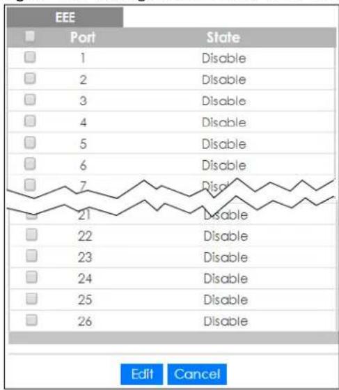
The following table describes the labels in this screen.
Table 68 Configuration > Port > EEE > EEE
| LABEL DESCRIPTION | |
| EEE | |
| Port Displays the port index number. | |
| State Displays the port status as enabled or disabled. | |
| Edit | Select this check box to configure the properties of a port. Click the Edit button change the properties of the port. |
| Cancel | Click Cancel to discard the changes. |
19.3.2 EEE Edit
Use this screen to configure Switch port EEE settings. Click Configuration > Port > EEE > EEE > Edit to open this screen.
Figure 136 Configuration > Port > EEE > EEE > Edit
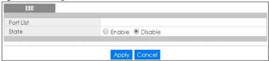
The following table describes the labels in this screen.
Table 69 Configuration > Port > EEE > EEE > Edit
| LABEL DESCRIPTION | |
| EEE | |
| Port List | Displays the list of port index numbers that are being configured. |
| State | Select Enable to designate the ports as EEE or Disable to not designate them as EEE. |
| Apply | Click Apply to save the changes. |
| Cancel | Click Cancel to discard the changes. |
19.4 PoE Settings
The Switch supports both the IEEE 802.3af Power over Ethernet (PoE) and IEEE 802.3at High Power over Ethernet (PoE) standards. The Switch is Power Sourcing Equipment (PSE) because it provides a source of power through its Ethernet ports, and each device that receives power through an Ethernet port is a Powered Device (PD).
19.4.1 Global Settings
In the navigation panel, click Configuration > Port > PoE > Global to display the screen as shown. Use this screen to configure Power over Ethernet (PoE) global settings.
Figure 137 Configuration > Port > PoE > Global

The following table describes the labels in this screen.
Table 70 Configuration > Port > PoE > Global
| LABEL DESCRIPTION | |
| PoE Mode Select the power management mode you want the Switch to use. | Classification– Select this if you want the Switch to reserve the maximum power for each PD according to the PD's power class and priority level. If the total power supply runs out, PDs with lower priority do not get power to function. In this mode, the maximum power is reserved based on what you configure inMax Poweror the standard power limit for each class.Consumption– Select this if you want the Switch to supply the actual power that the PD needs. The Switch also allocates power based on a port'sMax Powerand the PD's power class and priority level. The Switch puts a limit on the maximum amount of power the PD can request and use. In this mode, the default maximum power that can be delivered to the PD is 33 W (IEEE 802.3at Class 4) or 22 W (IEEE 802.3af Classes 0 to 3). |
| Pre-Allocate | This field is only available on GS1900-8HP (Revision B1) and GS1900-10HP only.SelectEnableto have the Switch pre-allocate power to each port based on the classification of the PD device. Otherwise, selectDisable. |
| Apply | ClickApplyto save the changes. |
| Cancel | ClickCancelto discard the changes. |
19.4.2 Port Settings
Use this screen to view Switch port PoE settings and select ports for configuration. Click Configuration >Port >PoE >Port to open this screen.
Figure 138 Configuration > Port > PoE > Port
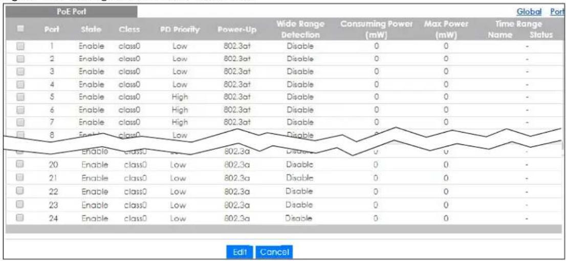
The following table describes the labels in this screen.
Table 71 Configuration > Port > PoE > Port
| LABEL DESCRIPTION | |
| Edit | Select one or more ports in the first column of the table and click this to configure PoE settings for the ports. |
| Port Displays the port index number. | |
| State | Displays which ports can receive power from the Switch. You can set this in theConfiguration> Port > PoE Edit screen.Disable– The powered device (PD) connected to this port cannot get power.Enable– The PD connected to this port can receive power. |
| Class | This shows the power classification of the PD. Each PD has a specified maximum power that fall under one of the classes.The Class is a number from 0 to 4, where each value represents the range of power that the Switch provides to the PD. The power ranges for each class are as follows.Class 0– Default, 0.44 to 12.94Class 1– Optional, 0.44 to 3.84Class 2– Optional, 3.84 to 6.49Class 3– Optional, 6.49 to 12.95Class 4– Reserved (PSEs classify as Class 0) in a switch that supports IEEE 802.3af only.Optional, 12.95 to 25.50 in a switch that supports IEEE 802.3af. |
| PD Priority | When the total power requested by the PDs exceeds the total PoE power budget on the Switch, you can set the PD priority to allow the Switch to provide power to ports with higher priority first.Criticalhas the highest priority.Highhas the Switch assign power to the port after all critical priority ports are served.Mediumhas the Switch assign power to the port after all critical and high priority ports are served.Lowhas the Switch assign power to the port after all critical, high and medium priority ports are served. |
| Power-Up This shows how the Switch provides power to the connected PD at power-up.802.3af – the Switch follows the IEEE 802.3af Power over Ethernet standard to supply power to the connected PDs during power-up.Legacy – the Switch can provide power to the connected PDs that require high inrush currents at power-up.Pre-802.3at – the Switch initially offers power on the port according to the IEEE 802.3af standard, and then switches to support the IEEE 802.3at standard within 75 milliseconds after a PD is connected to the port. Select this option if the Switch is performing 2-event Layer-1 classification (PoE+ hardware classification) or the connected PD is NOT performing Layer 2 power classification using Link Layer Discovery Protocol (LLDP).802.3at – the Switch supports the IEEE 802.3at High Power over Ethernet standard and can supply power of up to 30W per Ethernet port. IEEE 802.3at is also known as PoE+ or PoE Plus. An IEEE 802.3at compatible device is referred to as Type 2. Power Class 4 (High Power) can only be used by Type 2 devices. If the connected PD requires a Class 4 current when it is turned on, it will be powered up in this mode. | |
| Wide Range Detection | This field is available on GS1900-8HP (Revision B1) and GS1900-10HP only.This shows whether the Switch enables a wider detection range for the PD or not.The Switch detects whether a connected device is a powered device or not before supplying power to the port. For the PD detection, the Switch applies a fixed voltage to the device and then receives returned current. If the returned current is within the IEEE 802.3AF/AT standard range, the device will be considered as a valid PD by the Switch.However, in real cases, environmental interferences might easily cause the returned current out of the standard range. This field displays Enable if the Switch applies a wider range for PD detection. Otherwise, it displays Disable. |
| Consuming Power (mW) | This field displays the current amount of power consumed by the PD from the Switch on this port. |
| Max Power (mW) | This field displays the maximum amount of power the PD could use from the Switch on this port. |
| Time Range | |
| Name | This field displays the name of the time range (schedule) rule which is applied to the port. PoE is enabled at the specified time or date. |
| Status | This field displays whether the port can receive power from the Switch (In) or not (Out) currently.It shows – if there is no schedule applied to the port. |
19.4.3 PoE Edit
Use this screen to configure Switch port PoE settings. Select a port and click Edit in the Configuration >Port >PoE >Port screen to open this screen.
Figure 139 Configuration > Port > PoE > Port > Edit
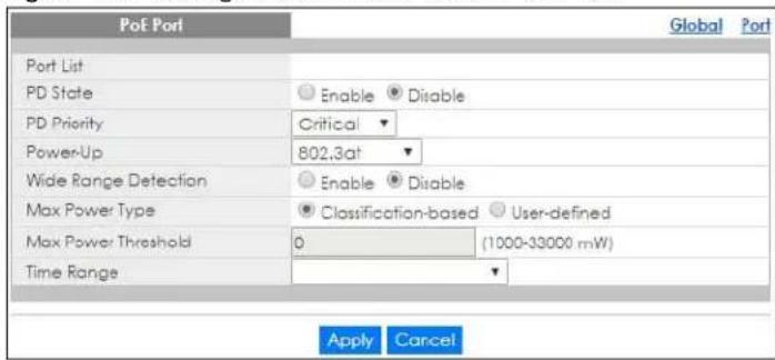
The following table describes the labels in this screen.
Table 72 Configuration > Port > PoE > Port > Edit
| LABEL DESCRIPTION | |
| PoE Port | |
| Port List | Displays the list of port index numbers that are being configured. |
| PD State | Select Enable to provide power to a PD connected to the port or Disable so the port cannot receive power from the Switch. |
| PD Priority This field | is not available for the SFP or SFP+ ports.When the total power requested by the PDs exceeds the total PoE power budget on the Switch, you can set the PD priority to allow the Switch to provide power to ports with higher priority.Select Critical to give the PD connected to this port the highest priority.Select High to set the Switch to assign the remaining power to the port after all critical priority ports are served.Select Medium to set the Switch to assign the remaining power to the port after all critical and high priority ports are served.Select Low to set the Switch to assign the remaining power to the port after all critical, high and medium priority ports are served. |
| Power-Up Set how | the Switch provides power to a connected PD at power-up.802.3af – the Switch follows the IEEE 802.3af Power over Ethernet standard to supply power to the connected PDs during power-up.Legacy – the Switch can provide power to the connected PDs that require high inrush currents at power-up.Pre-802.3at – the Switch initially offers power on the port according to the IEEE 802.3af standard, and then switches to support the IEEE 802.3at standard within 75 milliseconds after a PD is connected to the port. Select this option if the Switch is performing 2-event Layer-1 classification (PoE+ hardware classification) or the connected PD is NOT performing Layer 2 power classification using Link Layer Discovery Protocol (LLDP).802.3at – the Switch supports the IEEE 802.3at High Power over Ethernet standard and can supply power of up to 30W per Ethernet port. IEEE 802.3at is also known as PoE+ or PoE Plus. An IEEE 802.3at compatible device is referred to as Type 2. Power Class 4 (High Power) can only be used by Type 2 devices. If the connected PD requires a Class 4 current when it is turned on, it will be powered up in this mode. |
| Wide Range Detection | This field is available on the GS1900-8HP (Revision B1) and GS1900-10HP only.Select whether to enable a wider detection range for the PD or not.The Switch detects whether a connected device is a powered device or not before supplying power to the port. For the PD detection, the Switch applies a fixed voltage to the device and then receives returned current. If the returned current is within the IEEE 802.3AF/AT standard range, the device will be considered as a valid PD by the Switch.However, in real cases, environmental interferences might easily cause the returned current out of the standard range. This field displays Enable if the Switch applies a wider range for PD detection. Otherwise, it displays Disable. |
| Max Power Type | Select Classification-based to have the Switch automatically decide the maximum amount of power it can provide on the port according to the connected PD's power classification.Select User-defined to manually specify the maximum amount of power the PD could use from the Switch on this port. |
| Max Power Threshold | Specify the maximum amount of power the Switch can provide on the port if you set Max Power Type to User-defined.Enter a value between 1000 and 33000 in increments of 200. |
| Time Range | Select a pre-defined schedule (created using the Time Range screen) to control when the Switch enables PoE to provide power on the port.If you leave this field blank, there is no schedule applied to the port. |
| Apply | Click Apply to save the changes. |
| Cancel | Click Cancel to discard the changes. |
19.5 Bandwidth Management
Bandwidth management means defining a maximum allowable bandwidth for incoming and/or outgoing traffic flows on a port.
19.5.1 Bandwidth Control
Use this screen to view Egress Bandwidth Management settings and select ports for configuration. Click Configuration > Port > Bandwidth Management > Egress Global Burst to open this screen.
Figure 140 Configuration > Port > Bandwidth Management > Egress Global Burst
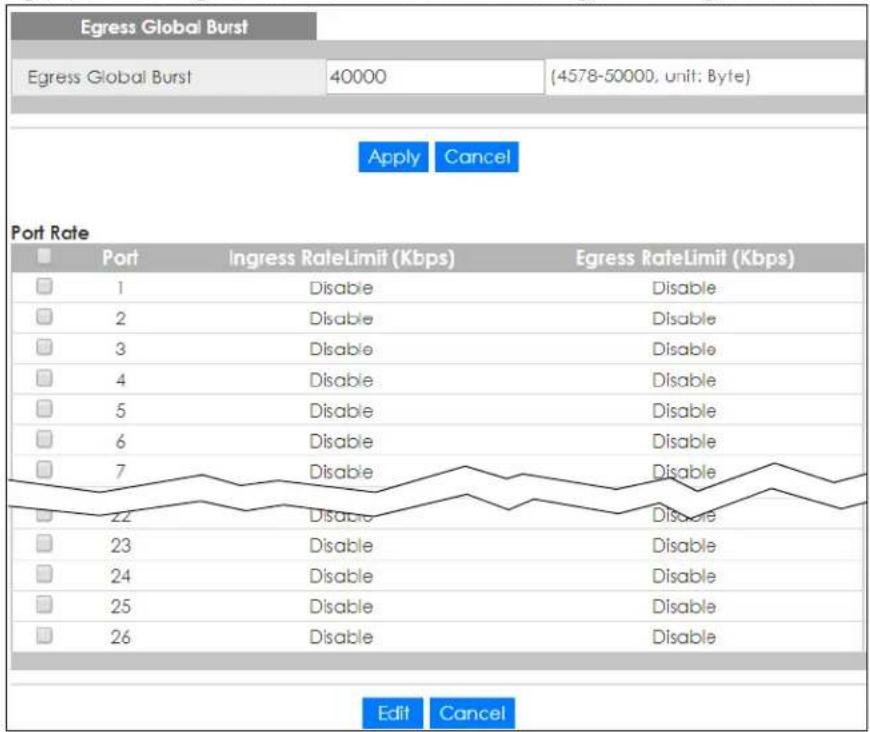
The following table describes the labels in this screen.
Table 73 Configuration > Port > Bandwidth Management > Egress Global Burst
| LABEL DESCRIPTION | |
| Egress Global Burst | |
| Egress Global Burst | Specify the current egress burst size in bytes for all ports. |
| Port Rate | |
| Port Displays the port index number. | |
| Ingress Rate Limit (Kbps) | Displays the maximum bandwidth allowed in kilobits per second (Kbps) for the incoming traffic flow on a port. |
| Egress Rate Limit (Kbps) | Displays the maximum bandwidth allowed in kilobits per second (Kbps) for the outgoing traffic flow on a port. |
| Edit | Select this check box to configure the properties of a port. Click the Edit button change the properties of the port. |
| Cancel | Click Cancel to discard the changes. |
19.5.2 Port Rate Edit
Use this screen to configure port rate Bandwidth Management settings. Click Configuration > Port > Bandwidth Management > Egress Global Burst > Edit to open this screen.
Figure 141 Configuration > Port > Bandwidth Management > Egress Global Burst > Edit
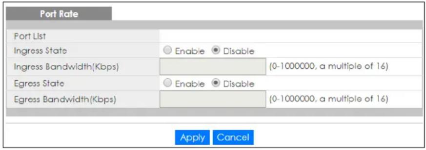
The following table describes the labels in this screen.
Table 74 Configuration > Port > Bandwidth Management > Egress Global Burst > Edit
| LABEL DESCRIPTION | |
| Port Rate | |
| Port List | Displays the list of port index numbers that are being configured. |
| Ingress State | Select Enable to activate ingress peak rate limits on the ports. |
| Ingress Bandwidth (Kbps) | Enter the maximum bandwidth allowed in kilobits per second (Kbps) for the outgoing traffic flow on a port. |
| Egress State | Select Enable to activate egress peak rate limits on the ports. |
| Egress Bandwidth (Kbps) | Enter the maximum bandwidth allowed in kilobits per second (Kbps) for the outgoing traffic flow on a port. |
| Apply | Click Apply to save the changes. |
| Cancel | Click Cancel to discard the changes. |
19.6 Storm Control
Broadcast storm control limits the number of broadcast, multicast and destination lookup failure (DLF) packets the Switch receives per second on the ports. When the maximum number of allowable broadcast, multicast and/or DLF packets is reached per second, the subsequent packets are discarded. Enable this feature to reduce broadcast, multicast and/or DLF packets in your network. You can specify limits for each packet type on each port.
19.6.1 Port Settings
Use this screen to view Storm Control settings for individual ports. Click Configuration > Port > Storm Control > Storm Control to open this screen.
Figure 142 Configuration > Port > Storm Control > Storm Control
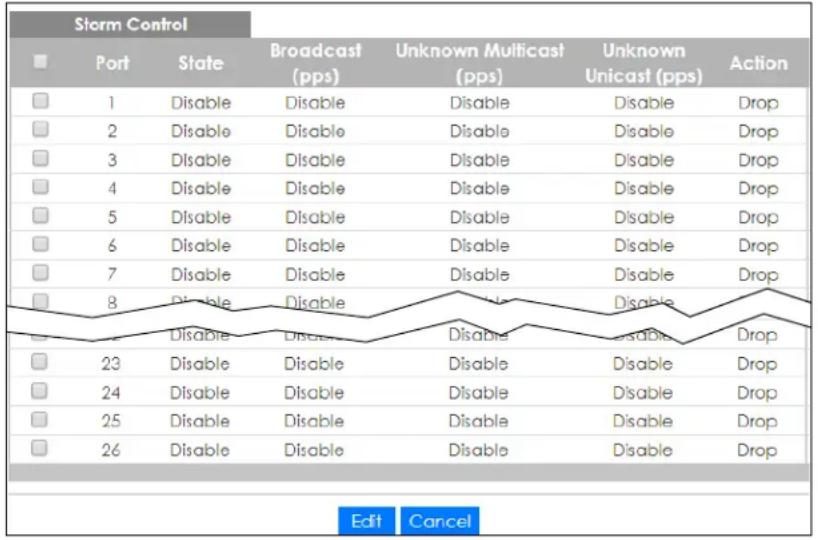
The following table describes the labels in this screen.
Table 75 Configuration > Port > Storm Control > Storm Control
| LABEL DESCRIPTION | |
| Storm Control | |
| Port Displays the port index number. | |
| State Displays whether the traffic storm control on the Switch is enabled or disabled. | |
| Broadcast (pps) | Displays how many broadcast packets the port receives per second. |
| Unknown Multicast (pps) | Displays how many multicast packets the port receives per second. |
| Unknown Unicast (pps) | Displays how many unicast packets the port receives per second. |
| Action | Displays the action the device takes when a limit is reached. The following options are available:Drop – drop the packet.Shutdown – shutdown the connection. |
| Edit | Select this check box to configure the properties of a port. Click the Edit button change the properties of the port. |
| Cancel | Click Cancel to discard the changes. |
19.6.2 Port Edit
Use this screen to configure Storm Control settings for individual ports. Click Configuration > Port > Storm Control > Storm Control > Edit to open this screen.
Figure 143 Configuration > Port > Storm Control > Storm Control > Edit
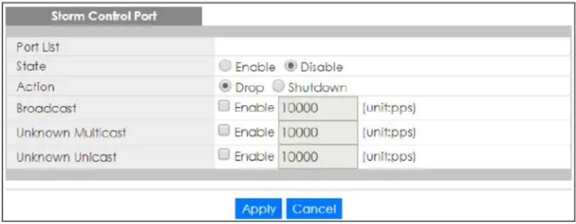
The following table describes the labels in this screen.
Table 76 Configuration > Port > Storm Control > Storm Control > Edit
| LABEL DESCRIPTION | |
| Storm Control Port | |
| Port List Displays the port list index numbers. | |
| State | Select Enable to activate traffic storm control on the ports. |
| Action | Determines the action the device takes when a limit is reached. The following options are available:Drop – drop the packet when limit is reached.Shutdown – shutdown the connection when a limit is reached. |
| Broadcast (pps) | Click the Enable checkbox to active the feature.Enter the maximum number of broadcast packets the port can receive per second. |
| Unknown Multicast (pps) | Click the Enable checkbox to active the feature.Enter the maximum number of multicast packets the port can receive per second. |
| Unknown Unicast (pps) | Click the Enable checkbox to active the feature.Enter the maximum number of unicast packets the port can receive per second. |
| Apply | Click Apply to save the changes. |
| Cancel | Click Cancel to discard the changes. |
CHAPTER 20
Configuration: VLAN
20.1 Overview
This section provides information for VLAN in Configuration.
A VLAN (Virtual Local Area Network) allows a physical network to be partitioned into multiple logical networks. Devices on a logical network belong to one group. A device can belong to more than one group. With VLAN, a device cannot directly talk to or hear from devices that are not in the same groups; the traffic must first go through a router.
In MTU (Multi-Tenant Unit) applications, VLAN is vital in providing isolation and security among the subscribers. When properly configured, VLAN prevents one subscriber from accessing the network resources of another on the same LAN, therefore a user will not see the printers and hard disks of another user on the same network.
VLAN also increases network performance by limiting broadcasts to a smaller and more manageable logical broadcast domain. In traditional switched environments, all broadcast packets go to each and every individual port. With VLAN, all broadcasts are confined to a specific broadcast domain.
20.1.1 What You Can Do in this Chapter
- The VLAN screen (Section 20.2 on page 139) displays VLAN, port, and VLAN port settings.
- The Guest VLAN screen (Section 20.3 on page 143) displays the global and port settings of the Switch.
- The Voice VLAN screen (Section 20.4 on page 145) displays the global, OUI, and port settings of the Switch.
20.2 VLAN Settings
Use this screen to view and configure VLAN settings.
20.2.1 VLAN
Use this screen to view VLAN settings. Click Configuration > VLAN > VLAN > VLAN to open this screen.
Figure 144 Configuration > VLAN > VLAN > VLAN
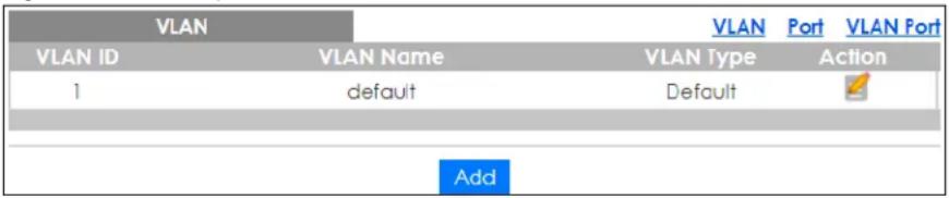
The following table describes the labels in this screen.
Table 77 Configuration > VLAN > VLAN > VLAN
| LABEL DESCRIPTION | |
| VLAN | |
| VLAN ID Displays the VLAN ID number. | |
| VLAN Name | Displays a descriptive name for the VLAN group for identification purposes. This name consists of up to 64 printable characters; spaces are allowed. |
| VLAN Type | Displays Default or Static. |
| Action | |
| Edit | Click Edit to make changes to the entry. |
| Add | Click Add to create a new VLAN entry. |
20.2.2 VLAN Add
Use this screen to add a VLAN. Click Configuration > VLAN > VLAN > VLAN > Add to open this screen.
Figure 145 Configuration > VLAN > VLAN > VLAN > Add
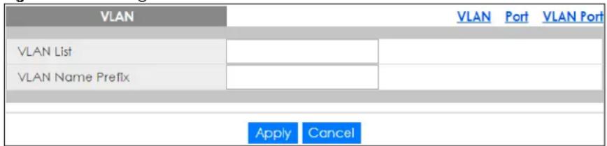
The following table describes the labels in this screen.
Table 78 Configuration > VLAN > VLAN > VLAN > Add
| LABEL DESCRIPTION | |
| VLAN | |
| VLAN List Enter the | VLAN ID numbers.Use a dash to associate consecutive VLANs and a comma (no spaces) to associate non-consecutive VLANs. For example, 51–53 includes 51, 52 and 53, but 51,53 does not include 52. |
| VLAN Name Prefix | Enter a prefix for the VLAN name. |
| Apply | ClickApplyto save the changes. |
| Cancel | ClickCancelto discard the changes. |
20.2.3 Port Settings
Use this screen to view port settings and select VLANs for configuration. Click Configuration > VLAN > VLAN > Port to open this screen.
Figure 146 Configuration > VLAN > VLAN > Port
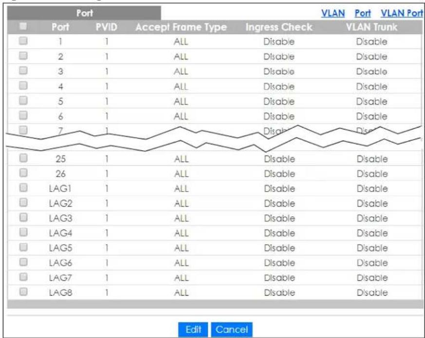
The following table describes the labels in this screen.
Table 79 Configuration > VLAN > VLAN > Port
| LABEL DESCRIPTION | |
| Port | |
| Port Displays the port index number. | |
| PVID | A PVID (Port VLAN ID) is a tag that adds to incoming untagged frames received on a port so that the frames are forwarded to the VLAN group that the tag defines. |
| Accept Frame Type | Specify the type of frames allowed on a port. Choices are All, Tag Only and Untag Only. |
| Ingress Check | If this check box is selected for a port, the Switch discards incoming frames for VLANs that do not include this port in its member set. |
| VLAN Trunk | Enable VLAN Trunking on ports connected to other switches or routers (but not ports directly connected to end users) to allow frames belonging to unknown VLAN groups to pass through the Switch. |
| Edit | Select this check box to configure the properties of a port. Click the Edit button change the properties of the port. |
| Cancel | Click Cancel to discard the changes. |
20.2.4 Port Edit
Use this screen to configure port settings. Click Configuration > VLAN > VLAN > Port > Edit to open this screen.
Figure 147 Configuration > VLAN > VLAN > Port > Edit
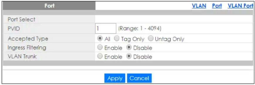
The following table describes the labels in this screen.
Table 80 Configuration > VLAN > VLAN > Port > Edit
| LABEL DESCRIPTION | |
| Port | |
| Port Select | Displays the list of port index numbers that are being configured. |
| PVID Enter a number | er between 1 and 4094 as the port VLAN ID. |
| Accepted Type | Select All from the drop-down list box to accept all untagged or tagged frames on this port. This is the default setting.Select Tag Only to accept only tagged frames on this port. All untagged frames will be dropped.Select Untag Only to accept only untagged frames on this port. All tagged frames will be dropped. |
| Ingress Filtering | If this check box is selected for a port, the Switch discards incoming frames for VLANs that do not include this port in its member set.Clear this check box to disable ingress filtering. |
| VLAN Trunk | Enable VLAN Trunking on ports connected to other switches or routers (but not ports directly connected to end users) to allow frames belonging to unknown VLAN groups to pass through the Switch. |
| Apply | Click Apply to save the changes. |
| Cancel | Click Cancel to discard the changes. |
20.2.5 VLAN Port
Port-based VLANs are VLANs where the packet forwarding decision is based on the destination MAC address and its associated port. Port-based VLANs require allowed outgoing ports to be defined for each port. Therefore, if you wish to allow two subscriber ports to talk to each other, for example,
between conference rooms in a hotel, you must define the egress (an egress port is an outgoing port, that is, a port through which a data packet leaves) for both ports. Port-based VLANs are specific only to the Switch on which they were created.
Use this screen to view VLAN port settings. Click Configuration > VLAN > VLAN > VLAN Port to open this screen.
Figure 148 Configuration > VLAN > VLAN > VLAN Port
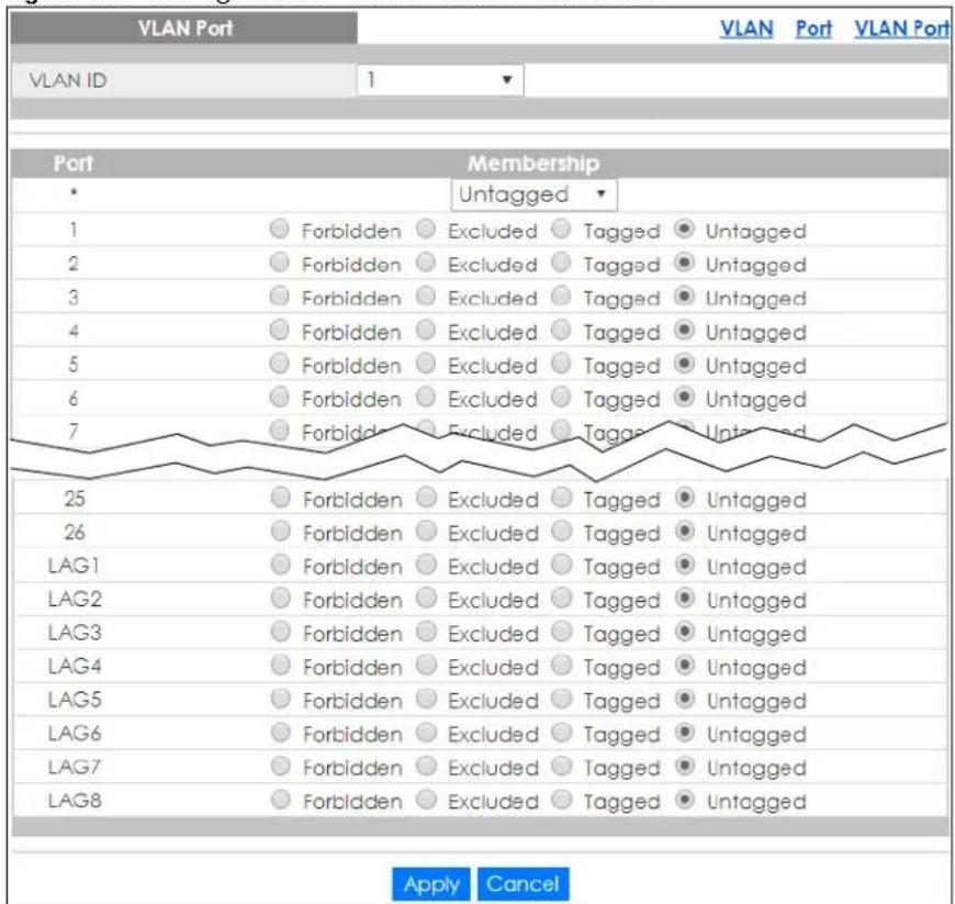
The following table describes the labels in this screen.
Table 81 Configuration > VLAN > VLAN > VLAN Port
| LABEL DESCRIPTION | |
| VLAN Port | |
| VLAN ID Select the | ID of the VLAN you want to configure. |
| Port Displays the port index value. | |
| Membership | Select Forbidden if you want to prohibit the port from joining this VLAN group.Select Excluded to remove the port from the VLAN.Select Tagged to set the port TX tag status to tagged in the VLAN.Select Untagged to set the port TX tag status to untagged in the VLAN. |
| Apply | Click Apply to save the changes. |
| Cancel | Click Cancel to discard the changes. |
20.3 Guest VLAN
When 802.1x port authentication is enabled on the Switch and its ports, clients that do not have the correct credentials are blocked from using the ports. You can configure your Switch to have one VLAN that acts as a guest VLAN. If you enable the guest VLAN (102 in the example) on a port (2 in the example), the user (A in the example) that is not IEEE 802.1x capable or fails to enter the correct user name and password can still access the port, but traffic from the user is forwarded to the guest VLAN. That is, unauthenticated users can have access to limited network resources in the same guest VLAN, such as the Internet. The rights granted to the Guest VLAN depends on how the network administrator configures switches or routers with the guest network feature.
Figure 149 Guest VLAN Example
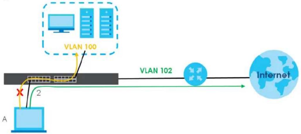
flowchart
graph LR
    A["Router A"] -->|2| B["VLAN 100"]
    B --> C["VLAN 102"]
    C --> D["Internet"]
    style A fill:#cce5ff,stroke:#333
    style B fill:#e6f7ff,stroke:#333
    style C fill:#ffe6cc,stroke:#333
    style D fill:#cce5ff,stroke:#333
Use this screen to view and configure guest VLAN settings.
20.3.1 Global Settings
Use this screen to configure the global Guest VLAN settings. Click Configuration > VLAN > Guest VLAN > Global to open this screen.
Figure 150 Configuration > VLAN > Guest VLAN > Global
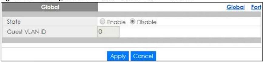
The following table describes the labels in this screen.
Table 82 Configuration > VLAN > Guest VLAN > Global
| LABEL DESCRIPTION | |
| Global | |
| State Select to enable the global Guest VLAN feature. | |
| Guest VLAN ID Enter the global guest VLAN ID. | |
| Apply | Click Apply to save the changes. |
| Cancel | Click Cancel to discard the changes. |
20.3.2 Port Settings
Use this screen to view the Guest VLAN port settings and select VLAN ports for configuration. Click Configuration > VLAN > Guest VLAN > Port to open this screen.
Figure 151 Configuration > VLAN > Guest VLAN > Port
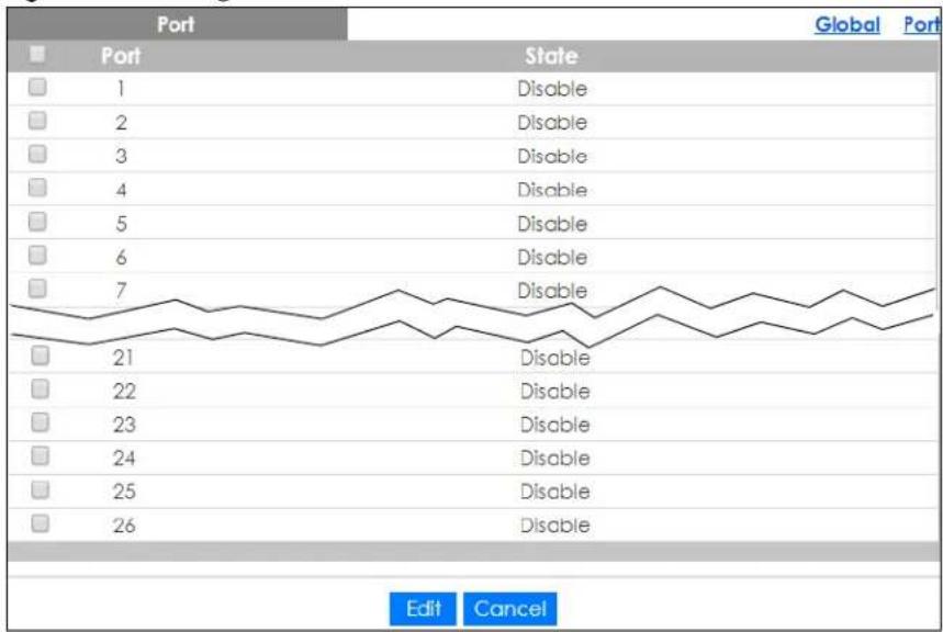
The following table describes the labels in this screen.
Table 83 Configuration > VLAN > Guest VLAN > Port
| LABEL DESCRIPTION | |
| Port | |
| Port Displays the port index number. | |
| State Display the state of the selected port. | |
| Edit | Select this check box to configure the properties of a port. Click the Edit button change the properties of the port. |
| Cancel | Click Cancel to discard the changes. |
20.3.3 Port Edit
Use this screen to configure the guest VLAN port EEE settings. Click Configuration > VLAN > Guest VLAN > Port > Edit to open this screen.
Figure 152 Configuration > VLAN > Guest VLAN > Port > Edit
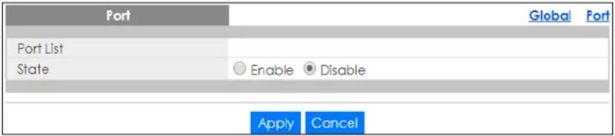
The following table describes the labels in this screen.
Table 84 Configuration > VLAN > Guest VLAN > Port > Edit
| LABEL DESCRIPTION | |
| Port | |
| Port List | Displays the list of port index numbers that are being configured. |
| State Enable/Disable the guest VLAN feature. | |
| Apply | ClickApplyto save the changes. |
| Cancel | ClickCancelto discard the changes. |
20.4 Voice VLAN
The Voice VLAN feature enables voice traffic forwarding on the Voice VLAN, then the switch can classify and schedule network traffic. It is recommended that there be two VLANs on a port – one for voice, one for data.
Use this screen to view and configure voice VLAN settings.
20.4.1 Global Settings
Use this screen to configure the global Voice VLAN settings. Click Configuration > VLAN > Voice VLAN > Global to open this screen.
Figure 153 Configuration > VLAN > Voice VLAN > Global
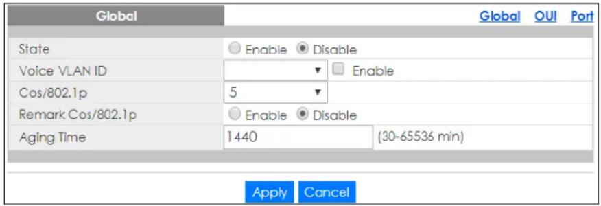
The following table describes the labels in this screen.
Table 85 Configuration > VLAN > Voice VLAN > Global
| LABEL DESCRIPTION | |
| Global | |
| State | Select Enable to activate the global voice VLAN feature. |
| Voice VLAN ID | Enter the global voice VLAN ID. It should be a unique VLAN ID in the system and cannot equal each port PVID. It is a conflict in configuration if the value equals management VID, MVR VID, PVID, and so on. The allowed range is 1 to 4094. |
| Cos/802.1p Displays the 802.1p packet priority field. | |
| Remark Cos/802.1p | Select to Enable the priority remark function for cos/802.1p. |
| Aging Time | Enter the voice VLAN secure learning aging time. The allowed range is 10 to 10000000 seconds. It is used when security mode or auto detect mode is enabled. In other cases, it will be based on hardware aging time. The actual aging time will be situated between the [age_time; 2 * age_time] interval. |
| Apply | Click Apply to save the changes. |
| Cancel | Click Cancel to discard the changes. |
20.4.2 OUI Settings
Use this screen to view the OUI settings. The maximum number of entries is 16. Modifying the OUI table will restart auto detection of OUI process. Click Configuration > VLAN > Voice VLAN > OUI to open this screen.
Figure 154 Configuration > VLAN > Voice VLAN > OUI
| OUI | Global | OUI | Port | |
| OUI Address | Description | Action | ||
| 00:E0:B8 | 3COM | |||
| 00:03:68 | Cisco | |||
| 00:E0:75 | Veritel | |||
| 00:D0:1E | Pingtel | |||
| 00:01:E3 | Siemens | |||
| 00:60:B9 | NEC/Philips | |||
| 00:0F:E2 | H3C | |||
| 00:09:6E | Avaya | |||
| Add | ||||
The following table describes the labels in this screen.
Table 86 Configuration > VLAN > Voice VLAN > OUI
| LABEL DESCRIPTION | |
| OUI | |
| OUI Address | Displays an OUI address. A telephony OUI address is a globally unique identifier assigned to a vendor by IEEE. It must be 6 characters long and the input format is "xx-xx-xx" (x is a hexadecimal digit). |
| Description | Displays a description of the OUI address. Normally, it describes which vendor telephony device it belongs to. The allowed string length is 0 to 32. |
| Action | |
| Edit | Click Edit to make changes to the entry. |
| Delete | Click Delete to remove the entry. |
| Add | Click Add to create a new OUI entry. |
20.4.3 OUI Add or Edit
Use this screen to add or edit an OUI address. Click Configuration > VLAN > Voice VLAN > OUI > Add or Edit to open this screen.
Figure 155 Configuration > VLAN > Voice VLAN > OUI > Add or Edit
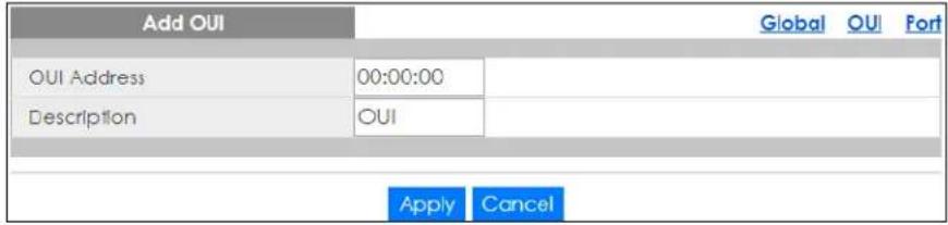
The following table describes the labels in this screen.
Table 87 Configuration > VLAN > Voice VLAN > OUI > Add or Edit
| LABEL DESCRIPTION | |
| Add/Edit OUI | |
| OUI Address | Enter an OUI address. A telephony OUI address is a globally unique identifier assigned to a vendor by IEEE. It must be 6 characters long and the input format is "xx-xx-xx" (x is a hexadecimal digit). |
| Description | Enter a description of the OUI address. Normally, it describes which vendor telephony device it belongs to. The allowed string length is 0 to 32. |
| Apply | Click Apply to save the changes. |
| Cancel | Click Cancel to discard the changes. |
20.4.4 Port Settings
Use this screen to view the Voice VLAN port settings and select a port for configuration. Click Configuration > VLAN > Voice VLAN > Port to open this screen.
Figure 156 Configuration > VLAN > Voice VLAN > Port
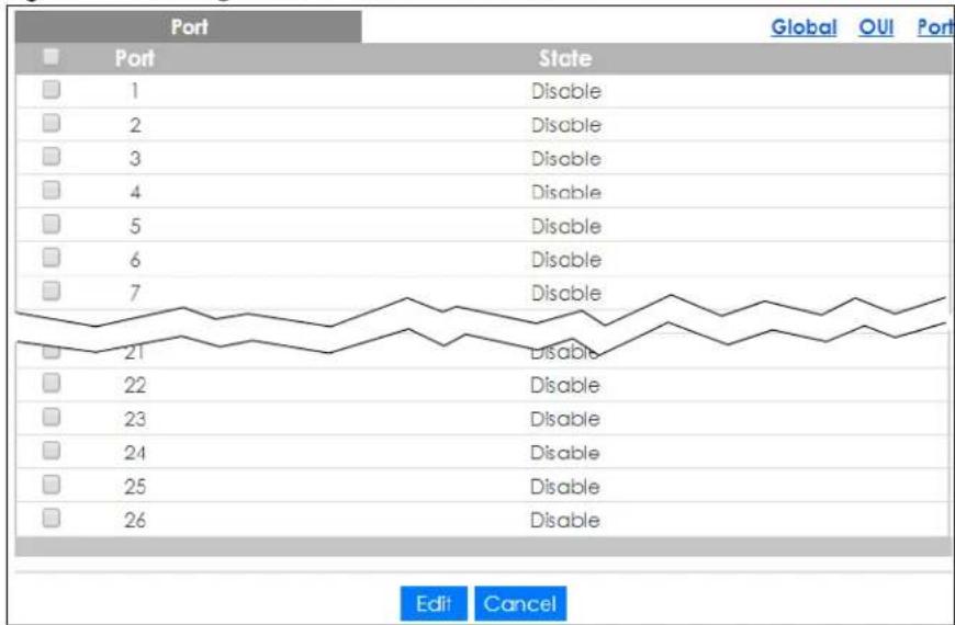
The following table describes the labels in this screen.
Table 88 Configuration > VLAN > Voice VLAN > Port
| LABEL DESCRIPTION | |
| Port | |
| Port Displays the port index value. | |
| State | Displays the Voice VLAN port security mode state. When the function is enabled, all non-telephonic MAC addresses in the Voice VLAN will be blocked for 10 seconds. Possible port modes are:Enabled: Enable Voice VLAN security mode operation.Disabled: Disable Voice VLAN security mode operation. |
| Edit | Select this check box to configure the properties of a port. Click the Edit button change the properties of the port. |
| Cancel | Click Cancel to discard the changes. |
20.4.5 Port Edit
Use this screen to edit the ports security state. Click Configuration > VLAN > Voice VLAN > Port > Edit to open this screen.
Figure 157 Configuration > VLAN > Voice VLAN > Port > Edit
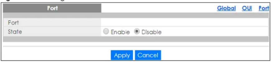
The following table describes the labels in this screen.
Table 89 Configuration > VLAN > Voice VLAN > Port > Edit
| LABEL DESCRIPTION | |
| Port | |
| Port Displays the ports index value. | |
| State | Select the Voice VLAN port security mode state. When the function is enabled, all non-telephonic MAC addresses in the Voice VLAN will be blocked for 10 seconds. Possible port modes are:Enabled: Enable Voice VLAN security mode operation.Disabled: Disable Voice VLAN security mode operation. |
| Apply | Click Apply to save the changes. |
| Cancel | Click Cancel to discard the changes. |
CHAPTER 21
Configuration: MAC Table
21.1 Overview
This section provides information for MAC Table in Configuration.
The MAC Table screen (a MAC table is also known as a filtering database) shows how frames are forwarded or filtered across the Switch's ports. When a device (which may belong to a VLAN group) sends a packet which is forwarded to a port on the Switch, the MAC address of the device is shown on the Switch's MAC Table. It also shows whether the MAC address is dynamic (learned by the Switch) or static (manually entered in the Static MAC Forwarding screen).
21.1.1 What You Can Do in this Chapter
The MAC Table screen displays Static MAC, Filtering MAC, and Dynamic MAC settings.
21.1.2 Static MAC
Use this screen to view Static MAC addresses settings. Click Configuration > MAC Table > Static MAC to open this screen.
Figure 158 Configuration > MAC Table > Static MAC
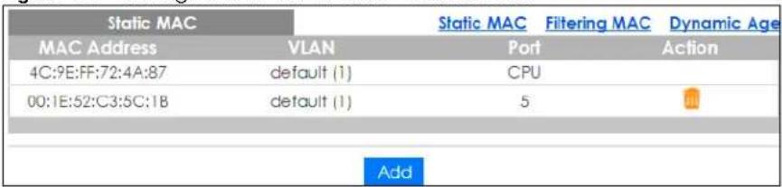
The following table describes the labels in this screen.
Table 90 Configuration > MAC Table > Static MAC
| LABEL DESCRIPTION | |
| Static MAC | |
| MAC Address | Displays the object MAC address from which this incoming frame came. |
| VLAN Displays the | VLAN group to which this frame belongs. |
| Port Displays the port from which the above MAC address was learned. | |
| Action Click Delete to remove the MAC address. | |
| Add | Click Add to create a new Static MAC entry. |
21.1.3 Static MAC Address
Use this screen to add new Static MAC addresses. Click Configuration > MAC Table > Static MAC > Add to open this screen.
Figure 159 Configuration > MAC Table > Static MAC > Add
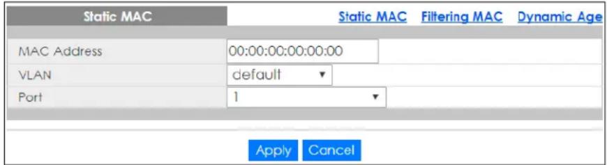
The following table describes the labels in this screen.
Table 91 Configuration > MAC Table > Static MAC > Add
| LABEL DESCRIPTION | |
| Static MAC | |
| MAC Address Enter the object MAC address. | |
| VLAN Select the VLAN group which to associate the MAC address. | |
| Port Select the port which to associate the above MAC address. | |
| Apply | Click Apply to save the changes. |
| Cancel | Click Cancel to discard the changes. |
21.1.4 Filtering MAC Address
Use this screen to view Filtering MAC addresses. Click Configuration > MAC Table > Filtering MAC to open this screen.
Figure 160 Configuration > MAC Table > Filtering MAC

The following table describes the labels in this screen.
Table 92 Configuration > MAC Table > Filtering MAC
| LABEL DESCRIPTION | |
| Filtering MAC | |
| MAC Address | Displays the filtering object MAC address from which this incoming frame came. |
| VLAN Displays the | VLAN group to which this frame belongs. |
| Action | |
| Delete | Click Delete to remove the entry. |
| Add | Click Add to create a new Filtering MAC entry. |
21.1.5 Filtering MAC Address (Add)
Use this screen to add new Filtering MAC addresses. Click Configuration > MAC Table > Filtering MAC > Add to open this screen.
Figure 161 Configuration > MAC Table > Filtering MAC > Add
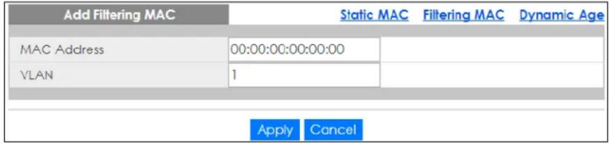
The following table describes the labels in this screen.
Table 93 Configuration > MAC Table > Filtering MAC > Add
| LABEL DESCRIPTION | |
| Add Filtering MAC | |
| MAC Address Enter | the MAC address of the device. |
| VLAN Select the VLAN group to associate the filtering object MAC address. | |
| Apply | ClickApplyto save the changes. |
| Cancel | ClickCancelto discard the changes. |
21.1.6 Dynamic Age
Use this screen to enter the Dynamic MAC Age. The dynamic MAC age is how long all dynamically learned MAC addresses remain in the MAC address table before they age out (and must be relearned). Click Configuration > MAC Table > Dynamic Age to open this screen.
Figure 162 Configuration > MAC Table > Dynamic Age

The following table describes the labels in this screen.
Table 94 Configuration > MAC Table > Dynamic Age
| LABEL DESCRIPTION | |
| Dynamic MAC Age | |
| Aging Time | Enter the aging time of the MAC address. The value can be between 10 and 630 seconds. |
| Apply | Click Apply to save the changes. |
| Cancel | Click Cancel to discard the changes. |
CHAPTER 22
Configuration: Link
Aggregation
22.1 Overview
This section provides information for Link Aggregation in Configuration.
This chapter shows you how to logically aggregate physical links to form one logical, higher bandwidth link.
22.1.1 What You Can Do in this Chapter
The Link Aggregation screen (Section 22.2 on page 152) displays global, LAG management, LAG port, and LACP port settings.
22.2 Link Aggregation
Link aggregation (trunking) is the grouping of physical ports into one logical higher-capacity link. You may want to trunk ports if for example, it is cheaper to use multiple lower-speed links than to under-utilize a high-speed, but more costly, single-port link.
However, the more ports you aggregate then the fewer available ports you have. A trunk group is one logical link containing multiple ports.
The Switch supports both static and dynamic link aggregation.
Note: In a properly planned network, it is recommended to implement static link aggregation only. This ensures increased network stability and control over the trunk groups on your Switch.
22.2.1 Global Settings
Use this screen to configure global Link Aggregation settings. Click Configuration > Link Aggregation > Global to open this screen.
Figure 163 Configuration > Link Aggregation > Global
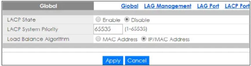
The following table describes the labels in this screen.
Table 95 Configuration > Link Aggregation > Global
| LABEL DESCRIPTION | |
| Global | |
| LACP State | Select Enable to activate the link aggregation control protocol. |
| LACP System Priority | LACP system priority is a number between 1 and 65,535. The switch with the lowest system priority (and lowest port number if system priority is the same) becomes the LACP “server”. The LACP “server” controls the operation of LACP setup. Enter a number to set the priority of an active port using Link Aggregation Control Protocol (LACP). The smaller the number, the higher the priority level. |
| Load Balance Algorithm | Select the outgoing traffic distribution type. Packets from the same source and/or to the same destination are sent over the same link within the trunk. By default, the Switch uses the IP/MAC Address distribution type. If the Switch is behind a router, the packet's destination or source MAC address will be changed. In this case, set the Switch to distribute traffic based on its IP address to make sure port trunking can work properly.Select MAC Address to distribute traffic based on a combination of the packet's source and destination MAC addresses.Select IP/MAC Address to distribute traffic based on a combination of the packet's source and destination IP addresses. |
| Apply | Click Apply to save the changes. |
| Cancel | Click Cancel to discard the changes. |
22.2.2 LAG Management
Use this screen to view LAG management settings. Click Configuration > Link Aggregation > LAG Management to open this screen.
Figure 164 Configuration > Link Aggregation > LAG Management

The following table describes the labels in this screen.
Table 96 Configuration > Link Aggregation > LAG Management
| LABEL DESCRIPTION | |
| LAG Management | |
| LAG | Displays the link aggregation group (LAG), that is, one logical link containing multiple ports. |
| Name Displays the | name of the link aggregation group. |
| Type This field disp | ays how these ports were added to the trunk group. It displays:Static – if the ports are configured as static members of a trunk group.LACP – if the ports are configured to join a trunk group through LACP. |
| Link Status | Displays link status as either Link up or Link down. |
| Active Member Dis | plays if this member is an active member of a trunk. |
| Standby Member | Displays if this member is an standby member of a trunk. |
| Action | |
| Edit | Click Edit to make changes to the entry. |
| Delete | Click Delete to remove the entry. |
| Add | Click Add to create a new LAG Management entry. |
22.2.3 LAG Management (Add)
Use this screen to add a LAG. Click Configuration > Link Aggregation > LAG Management > Add to open this screen.
Figure 165 Configuration > Link Aggregation > LAG Management > Add
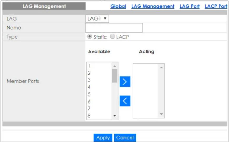
The following table describes the labels in this screen.
Table 97 Configuration > Link Aggregation > LAG Management > Add
| LABEL DESCRIPTION | |
| LAG Management | |
| LAG Select the link aggregation group (LAG). | |
| Name Enter the name of this entry. | |
| Type | Select Static or LACP. |
| Member Ports Select the member ports to be part of the LAG. | |
| Apply | Click Apply to save the changes. |
| Cancel | Click Cancel to discard the changes. |
22.2.4 LAG Port
Use this screen to view LAG port settings. Click Configuration > Link Aggregation > LAG Port to open this screen.
Figure 166 Configuration > Link Aggregation > LAG Port
| LAG Port | Global | LAG Management | LAG Port | LACP Port | ||||
| LAG | Name | Port Type | State | Speed | Duplex | FlowCtrl State | FlowCtrl Status | |
| LAG1 | Enable | Auto | Auto | Disable | Disable | |||
| LAG2 | Enable | Auto | Auto | Disable | Disable | |||
| LAG3 | Enable | Auto | Auto | Disable | Disable | |||
| LAG4 | Enable | Auto | Auto | Disable | Disable | |||
| LAG5 | Enable | Auto | Auto | Disable | Disable | |||
| LAG6 | Enable | Auto | Auto | Disable | Disable | |||
| LAG7 | Enable | Auto | Auto | Disable | Disable | |||
| LAG8 | Enable | Auto | Auto | Disable | Disable | |||
The following table describes the labels in this screen.
Table 98 Configuration > Link Aggregation > LAG Port
| LABEL DESCRIPTION | |
| LAG Port | |
| LAG Displays the L | LAG index value. |
| Name Displays the | LAG name. |
| Port Type Displays | the port type. |
| State | Displays the state as Enable or Disable. |
| Speed | Displays the speed value as Auto, Auto-10M, Auto-100M, Auto-1000M, Auto-10/100M, 10M, 100M, or 1000M. |
| Duplex | Displays the duplex value as Full, Half, or Auto. |
| FlowCtrl State | Displays whether flow control is Enable or Disable. |
| FlowCtrl Status | Displays whether flow control is in use (Enable) or not (Disable). |
| Edit | Select this check box to configure the properties of a port. Click the Edit button change the properties of the port. |
| Cancel | Click Cancel to discard the changes. |
22.2.5 LAG Port Edit
Use this screen to edit a LAG port. Click Configuration > Link Aggregation > LAG Port > Edit to open this screen.
Figure 167 Configuration > Link Aggregation > LAG Port > Edit
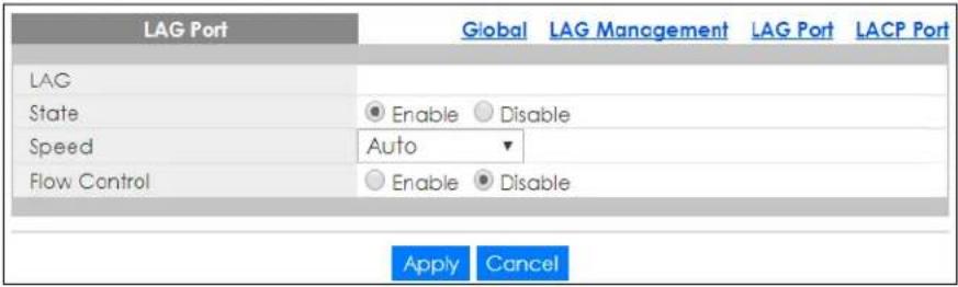
The following table describes the labels in this screen.
Table 99 Configuration > Link Aggregation > LAG Port > Edit
| LABEL DESCRIPTION | |
| LAG Port | |
| LAG Displays the L | LAG index values. |
| State | Select the state to be Enable or Disable. |
| Speed | Displays the speed value as Auto, 10M, 100M, or 1000M. |
| Flow Control | Select Enable to use the flow control feature. |
| Apply | Click Apply to save the changes. |
| Cancel | Click Cancel to discard the changes. |
22.2.6 LACP Port
Use this screen to view LACP Port settings. Click Configuration > Link Aggregation > LACP Port to open this screen.
Figure 168 Configuration > Link Aggregation > LACP Port
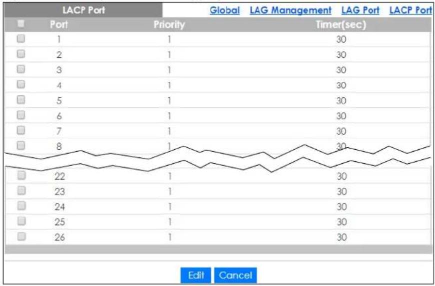
line
| Port | Priority | Timer(sec) | |---|---|---| | 1 | 1 | 30 | | 2 | 1 | 30 | | 3 | 1 | 30 | | 4 | 1 | 30 | | 5 | 1 | 30 | | 6 | 1 | 30 | | 7 | 1 | 30 | | 8 | 1 | 30 | | 22 | 1 | 30 | | 23 | 1 | 30 | | 24 | 1 | 30 | | 25 | 1 | 30 | | 26 | 1 | 30 | Edit CancelThe following table describes the labels in this screen.
Table 100 Configuration > Link Aggregation > LACP Port
| LABEL DESCRIPTION | |
| LACP Port | |
| Port Displays the port index number. | |
| Priority Displays the priority value. | |
| Timer (sec) Displays the Timer value in seconds. | |
| Edit | Select this check box to configure the properties of a port. Click the Edit button change the properties of the port. |
| Cancel | Click Cancel to discard the changes. |
22.2.7 LACP Port Edit
Use this screen to edit a LACP Port. Click Configuration > Link Aggregation > LACP Port > Edit to open this screen.
Figure 169 Configuration > Link Aggregation > LACP Port > Edit
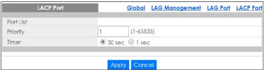
The following table describes the labels in this screen.
Table 101 Configuration > Link Aggregation > LACP Port > Edit
| LABEL DESCRIPTION | |
| LACP Port | |
| Port List Displays the list of port index numbers to be configured. | |
| Priority | Enter a value for the port priority. The number can be between 1 and 65,535. |
| Timer Select a timer value of either 1 second or 30 seconds. | |
| Apply | ClickApplyto save the changes. |
| Cancel | ClickCancelto discard the changes. |
CHAPTER 23
Configuration: Loop Guard
23.1 Overview
This section provides information for Loop Guard in Configuration.
This chapter shows you how to configure the Switch to guard against loops on the edge of your network.
23.2 Loop Guard
Loop guard allows you to configure the Switch to shut down a port if it detects that packets sent out on that port loop back to the Switch. While you can use Spanning Tree Protocol (STP) to prevent loops in the core of your network. STP cannot prevent loops that occur on the edge of your network.
23.2.1 Global Settings
Use this screen to configure the global Loop Guard. Click Configuration > Loop Guard > Global to open this screen.
Figure 170 Configuration > Loop Guard > Global
The following table describes the labels in this screen.
Table 102 Configuration > Loop Guard > Global
LABEL DESCRIPTION
| Global | |
| State | Select Enable to activate loop protection on this Switch. |
| Recovery Time | Enter the period (in seconds) for which a port will be kept disabled in the event of a loop is detected (and the port action shuts down the port). |
| Apply | Click Apply to save the changes. |
| Cancel | Click Cancel to discard the changes. |
23.2.2 Loop Guard Port
Use this screen to view the port's Loop Guard settings. Click Configuration > Loop Guard > Port to open this screen.
Figure 171 Configuration > Loop Guard > Port
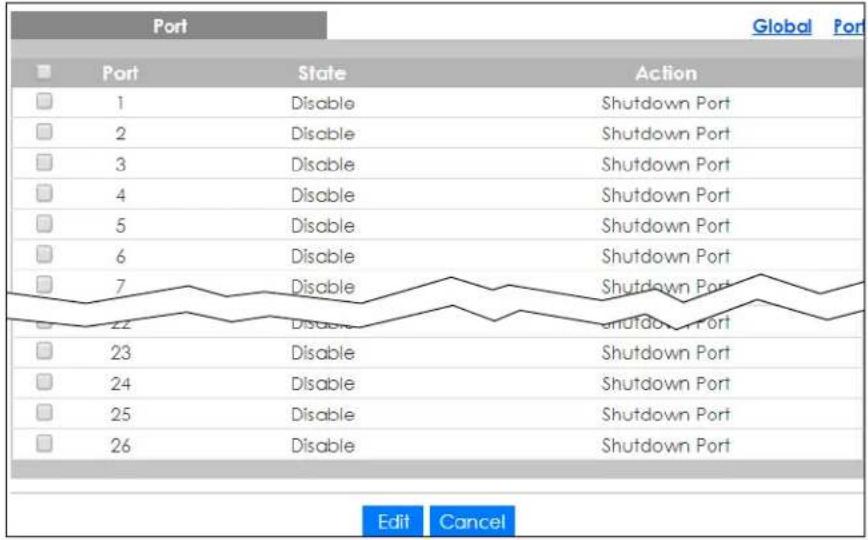
The following table describes the labels in this screen.
Table 103 Configuration > Loop Guard > Port
| LABEL DESCRIPTION | |
| Port | |
| Port Displays the port index number. | |
| State | Displays whether the loop guard feature is Enable or Disable on the port. |
| Action | Displays the action to take by the Switch. The options are Log, Shutdown Port, and Shutdown and Log. |
| Edit | Select this check box to configure the properties of a port. Click the Edit button change the properties of the port. |
| Cancel | Click Cancel to discard the changes. |
23.2.3 Port Edit
Use this screen to configure Loop Guard settings on a port. Click Configuration > Loop Guard > Port > Edit to open this screen.
Figure 172 Configuration > Loop Guard > Port > Edit
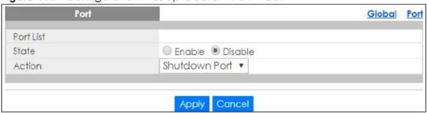
The following table describes the labels in this screen.
Table 104 Configuration > Loop Guard > Port > Edit
| LABEL DESCRIPTION | |
| Port | |
| Port List Displays the list of port index numbers to be configured. | |
| State Select to enable or disable the loop guard feature on the port. | |
| Action | Select to have the Switch shut down a port and/or generate a log message if it detects that packets sent out on that port loop back to the Switch. |
| Apply | Click Apply to save the changes. |
| Cancel | Click Cancel to discard the changes. |
CHAPTER 24
Configuration: Mirror
24.1 Overview
This section provides information for Mirror in Configuration.
24.2 Mirror Settings
Port mirroring allows you to copy a traffic flow to a monitor port (the port you copy the traffic to) in order that you can examine the traffic from the monitor port without interference.
The Switch supports local port mirroring.
24.2.1 Mirror
Use this screen to configure Mirroring. Click Configuration > Mirror to open this screen.
Figure 173 Configuration > Mirror
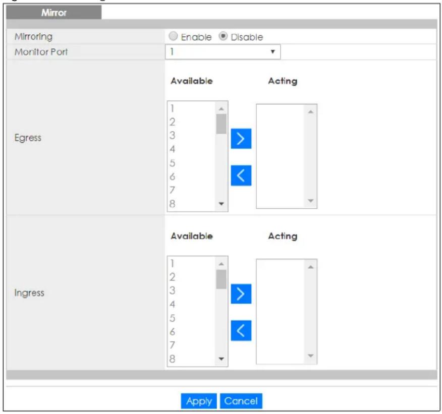
The following table describes the labels in this screen.
Table 105 Configuration > Mirror
| LABEL DESCRIPTION | |
| Mirror | |
| Mirroring | Select Enable to activate port mirroring on the Switch or Disable to disable the feature. |
| Monitor Port | The monitor port is the port you copy the traffic to in order to examine it in more detail without interfering with the traffic flow on the original ports. Type the port number of the monitor port. |
| Egress Specify the | ports to mirror outgoing traffic. |
| Available | Click < to move a severity type from the acting box to the available box.Click > to move a severity type to the acting box from the available box. |
| Acting | Click < to move a severity type from the acting box to the available box.Click > to move a severity type to the acting box from the available box. |
| > | Click > to move a severity type to the acting box from the available box. |
| < | Click < to move a severity type from the acting box to the available box. |
| Ingress Specify the | ports to mirror incoming traffic. |
| Available | Click < to move a severity type from the acting box to the available box.Click > to move a severity type to the acting box from the available box. |
| Acting | Click < to move a severity type from the acting box to the available box.Click > to move a severity type to the acting box from the available box. |
| >< | Click > to move a severity type to the acting box from the available box.Click < to move a severity type from the acting box to the available box. |
| Apply | Click Apply to save the changes. |
| Cancel | Click Cancel to discard the changes. |
CHAPTER 25
Configuration: Time Range
Group
25.1 Overview
You can set up one-time and recurring schedules for time-oriented features, such as PoE. The Switch supports one-time and recurring schedules. One-time schedules are effective only once, while recurring schedules usually repeat. Both types of schedules are based on the current date and time in the Switch.
25.1.1 What You Can Do
The Time Range Group screen (Section 25.2.1 on page 164) displays or defines a time range (schedule) rule on the Switch.
25.2 Time Range Group
Use this screen to view or edit a time range rule on the Switch.
25.2.1 Time Range Group Settings
Use this screen to view the time range rules. Click Configuration > Time Range Group in the navigation panel to display the screen as shown.
Figure 174 Configuration > Time Range Group
| Time Range Group | ||||
| Index | Name | Type | Range | Action |
| 1 | Weekday | Periodic | Weekdays 08:00 to 17:00 | |
| 2 | Weekend | Absolute | 2017/08/26 08:00 to 2017/08/27 17:0 0 | |
| Add | ||||
The following table describes the labels in this screen.
Table 106 Configuration > Time Range Group
| LABEL DESCRIPTION | |
| Index This field displays the index number of the rule. | |
| Name | This field displays the descriptive name for this rule. This is for identification purpose only. |
| Type This field displays the type of the rule. | |
| Range This field displays the time periods to which this rule applies. | |
| Action Click Edit to change the rule settings.Click Delete to remove the rule. | |
| Add Click Add to create a new time range rule. | |
25.2.2 Time Range Add
Use this screen to add a new time range (schedule) rule. Click Configuration > Time Range Group > Add in the navigation panel to display the screen as shown.
Figure 175 Configuration > Time Range Group > Add
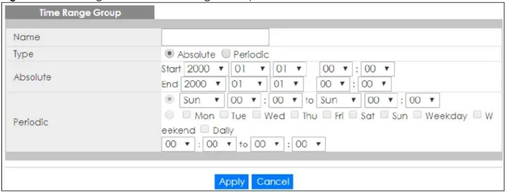
The following table describes the labels in this screen.
Table 107 Configuration > Time Range Group > Add
| LABEL DESCRIPTION | |
| Name Enter a descriptive name for this rule for identifying purposes. | |
| Type | SelectAbsoluteto create a one-time schedule. One-time schedules begin on a specific start date and time and end on a specific stop date and time. One-time schedules are useful for long holidays and vacation periods.Alternatively, selectPeriodicto create a recurring schedule. Recurring schedules begin at a specific start time and end at a specific stop time on selected days of the week (Sunday, Monday, Tuesday, Wednesday, Thursday, Friday, and Saturday). Recurring schedules are useful for defining the workday and off-work hours. |
| Absolute | This section is available only when you setType to Absolute. |
| Start Specify the year, month, day, hour and minute when the schedule begins. | |
| End Specify the year, month, day, hour and minute when the schedule ends. | |
| Periodic | This section is available only when you setType to Periodic.Select the first option if you want to define a recurring schedule for a consecutive time period. You then select the day of the week, hour and minute when the schedule begins and ends respectively.Select the second option if you want to define a recurring schedule for multiple non-consecutive time periods. You need to select each day of the week the recurring schedule is effective. You also need to specify the hour and minute when the schedule begins and ends each day. The schedule begins and ends in the same day. |
| Apply | Click Apply to save your changes to the Switch's run-time memory. The Switch loses these changes if it is turned off or loses power, so use the Save link on the top navigation panel to save your changes to the non-volatile memory when you are done configuring. |
| Cancel | Click Cancel to reset the fields to your previous configuration. |
25.2.3 Time Range Edit
Use this screen to modify an existing time range rule. Click Configuration > Time Range Group > Edit in the navigation panel to display the screens as shown.
25.2.3.1 Edit an Absolute Time Range Rule
Click the Edit button in the Action field to modify an absolute time range rule.
Figure 176 Configuration > Time Range Group > Edit (Absolute)
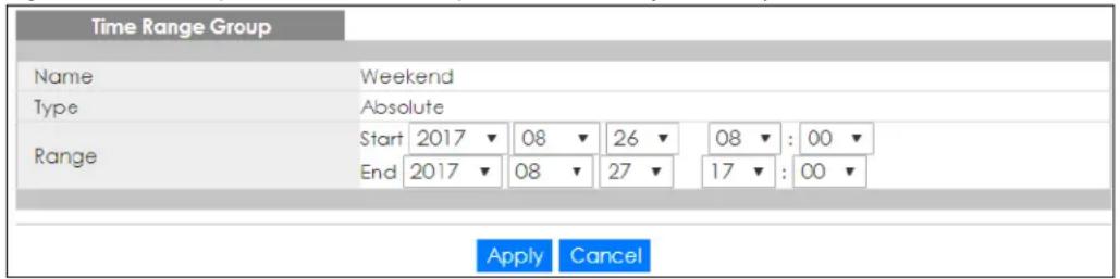
The following table describes the labels in this screen.
Table 108 Configuration > Time Range Group > Edit (Absolute)
| LABEL DESCRIPTION | |
| Name | This field displays the descriptive name for this rule. This is for identification purpose only. |
| Type This field displays the type of the rule. | |
| Range Specify the year, month, day, hour and minute when the schedule begins and ends. | |
| Apply | Click Apply to save your changes to the Switch's run-time memory. The Switch loses these changes if it is turned off or loses power, so use the Save link on the top navigation panel to save your changes to the non-volatile memory when you are done configuring. |
| Cancel | Click Cancel to reset the fields to your previous configuration. |
25.2.3.2 Edit a Periodic Time Range Rule
Click the Edit button in the Action field to modify a periodic time range rule. A screen will appear showing the name, type, and range of this rule. Click the Edit button again to modify it, or you can click the Add button to create a new range under a periodic time range rule.
Figure 177 Configuration > Time Range Group > Edit (Periodic)
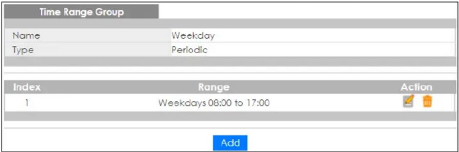
The following table describes the labels in this screen.
Table 109 Configuration > Time Range Group > Edit (Periodic)
| LABEL DESCRIPTION | |
| Time Range Group | |
| Name | This field displays the descriptive name for this rule. This is for identification purpose only. |
| Type This field displays the type of the rule. | |
| Index This field displays the index number of the rule. | |
| Range This field displays the time periods to which this rule applies. | |
| Action Click Edit to change the rule settings.Click Delete to remove the rule. | |
| Add Click Add to create a new range. | |
Figure 178 Configuration > Time Range Group > Edit (Periodic) > Add
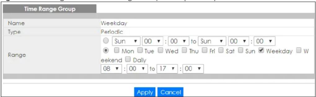
The following table describes the labels in this screen.
Table 110 Configuration > Time Range Group > Edit (Periodic) > Add
| LABEL DESCRIPTION | |
| Time Range Group | |
| Name Enter a descriptive name for this rule for identifying purposes. | |
| Type This field displays the type of the rule. | |
| Range | Select the first option if you want to define a recurring schedule for a consecutive time period. You then select the day of the week, hour and minute when the schedule begins and ends respectively.Select the second option if you want to define a recurring schedule for multiple non-consecutive time periods. You need to select each day of the week the recurring schedule is effective. You also need to specify the hour and minute when the schedule begins and ends each day. The schedule begins and ends in the same day. |
| Apply | Click Apply to save your changes to the Switch's run-time memory. The Switch loses these changes if it is turned off or loses power, so use the Save link on the top navigation panel to save your changes to the non-volatile memory when you are done configuring. |
| Cancel | Click Cancel to reset the fields to your previous configuration. |
CHAPTER 26
Configuration: Multicast
26.1 Overview
This section provides information for Multicast in Configuration.
Traditionally, IP packets are transmitted in one of either two ways – Unicast (1 sender to 1 recipient) or Broadcast (1 sender to everybody on the network). Multicast delivers IP packets to just a group of hosts on the network.
26.2 IGMP Settings
IGMP (Internet Group Management Protocol) is a network-layer protocol used to establish membership in an IPv4 multicast group – it is not used to carry user data. Refer to RFC 1112, RFC 2236 and RFC 3376 for information on IGMP versions 1, 2 and 3 respectively.
26.2.1 Global Settings
Use this screen to view the IGMP Global settings. Click Configuration > Multicast > IGMP > Global to open this screen.
Figure 179 Configuration > Multicast > IGMP > Global
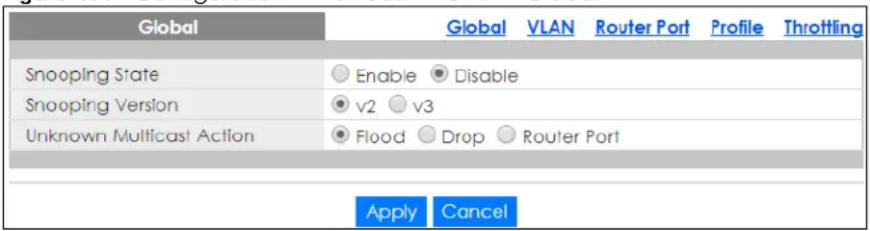
The following table describes the labels in this screen.
Table 111 Configuration > Multicast > IGMP > Global
| LABEL DESCRIPTION | |
| Global | |
| Snooping State | Select Enable to turn on IGMP packet snooping or Disable to turn snooping off. |
| Snooping Version | Select v2 or v3 depending on the snooping version you require. |
| Unknown Multicast Action | Select to send the IPv4 unknown multicast frame to the router port. The following options are available:•Flood – select to send the frames to all ports.•Drop – select to discard the frames.•Router Port– select to send the frame to router port. |
| Apply | ClickApplyto save the changes. |
| Cancel | ClickCancelto discard the changes. |
26.2.2 VLAN Settings
Use this screen to view the IGMP VLAN settings. Click Configuration > Multicast > IGMP > VLAN to open this screen.
Figure 180 Configuration > Multicast > IGMP > VLAN
| IGMP Vian | Global | VLAN | Router Port | Profile | Throttling | |||||||
| VLAN ID | State | Router Ports Auto Learn | Retry | Query Interval | Max. Response Interval | Last Member Query Count | Interval | Querier State | Version | |||
| 1 | Disable | Enable | 2 | 125 | 10 | 2 | 1 | Disable | --- | |||
The following table describes the labels in this screen.
Table 112 Configuration > Multicast > IGMP > VLAN
| LABEL DESCRIPTION | |
| IGMP Vlan | |
| VLAN ID Displays the status of the VLAN as enabled or disabled. | |
| State Display the status of the VLAN as enabled or disabled. | |
| Router Ports Auto Learn | Displays the Switch learn multicast router port member status of any VLANs as enabled or disabled. |
| Query | |
| Retry Displays the number of query retry times. | |
| Interval | Displays the amount of time (in seconds) between general query messages sent by the router connected to the upstream port. |
| Max. Response Interval (sec) | Displays the amount of time (in seconds) the router connected to the upstream port waits for a response to an IGMP general query message. |
| Last Member Query | |
| Count Displays the number of queries. | |
| Interval | Displays the amount of time (in milliseconds) between the IGMP group-specific queries sent by an upstream port when an IGMP Done message is received. |
| Querier | |
| State | Displays the Switch current VLAN querier entry as Enable or Disable. |
| Version Displays the Switch current VLAN querier entry version. | |
| Edit | Click Edit to change the properties of the IGMP VLAN entry. |
26.2.3 Edit IGMP
Use this screen to configure the IGMP VLAN settings. Click Configuration > Multicast > IGMP > VLAN > Edit to open this screen.
Figure 181 Configuration > Multicast > IGMP > VLAN > Edit
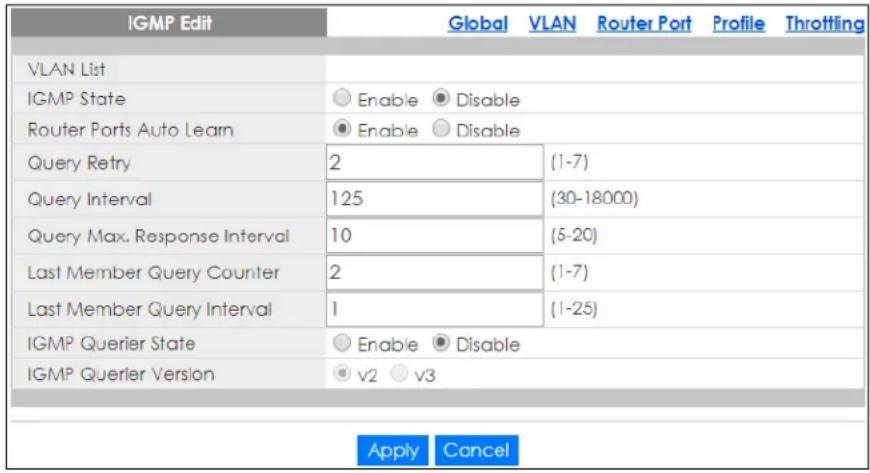
The following table describes the labels in this screen.
Table 113 Configuration > Multicast > IGMP > VLAN > Edit
| LABEL DESCRIPTION | |
| IGMP Edit | |
| VLAN List Enter the | ID of a static VLAN; the valid range is between 1 and 4094. |
| IGMP State | Select the status of the VLAN to Enable or Disable the function. |
| Router Ports Auto Learn | Select Enabled to have the Switch learn multicast router membership information of any VLANs automatically. |
| Query Retry Enter | the number of query retry times. The value can be between 1 and 7. |
| Query Interval | Enter the amount of time (in seconds) between general query messages sent by the router connected to the upstream port. The value can be between 30 and 18000. |
| Query Max. Response Interval | Enter the amount of time (in seconds) the router connected to the upstream port waits for a response to an IGMP general query message. |
| Last Member Query Count | Enter the number of queries. |
| Last Member Query Interval | Enter the amount of time (in seconds) between the IGMP group-specific queries sent by an upstream port when an IGMP Done message is received. |
| IGMP Querier State | Select the IGMP querier status to Enable or Disable the function. |
| IGMP Querier Version | Select the IGMP Querier version to v2 or v3. |
| Apply | Click Apply to save the changes. |
| Cancel | Click Cancel to discard the changes. |
26.2.4 Router Port
Use this screen to view the Router Port settings. Click Configuration > Multicast > IGMP > Router Port to open this screen.
Figure 182 Configuration > Multicast > IGMP > Router Port

The following table describes the labels in this screen.
Table 114 Configuration > Multicast > IGMP > Router Port
| LABEL DESCRIPTION | |
| Router Port | |
| VLAN ID Displays the ID of a static VLAN; the valid range is between 1 and 4094. | |
| Static Router Ports | Displays the ports that are defined as static router ports. |
| Forbidden Router Ports | Displays the ports that are defined as forbidden router ports. |
| Action | |
| Edit | Click Edit to make changes to the entry. |
| Delete | Click Delete to remove the entry. |
| Add | Click Add to create a new Router Port entry. |
26.2.5 Add or Edit Router Port
Use this screen to configure the Router Port settings. Click Configuration > Multicast > IGMP > Router Port > Add or Edit to open this screen.
Figure 183 Configuration > Multicast > IGMP > Router Port > Add or Edit
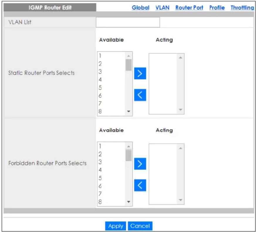
The following table describes the labels in this screen.
Table 115 Configuration > Multicast > IGMP > Router Port > Add or Edit
| LABEL DESCRIPTION | |
| IGMP Router Edit | |
| VLAN List | Enter the static VLAN IDs (valid range for each ID value is between 1 and 4094). |
| Static Router Ports Selects | Select the ports to be static router ports. |
| Forbidden Router Ports Selects | Select the ports to be forbidden router ports. |
| Apply | Click Apply to save the changes. |
| Cancel | Click Cancel to discard the changes. |
26.2.6 Profile Settings
Use this screen to view the IGMP Profile settings. Click Configuration > Multicast > IGMP > Profile to open this screen.
Figure 184 Configuration > Multicast > IGMP > Profile
| IGMP Profile | Global | VLAN | Router Port | Profile | Throttling | |
| Profile | Group From | Group To | Match Action | Action | ||
| Add | ||||||
The following table describes the labels in this screen.
Table 116 Configuration > Multicast > IGMP > Profile
| LABEL DESCRIPTION | |
| IGMP Profile | |
| Profile | Displays the Profile index number. |
| Group From Displays the profile start group IP address. | |
| Group To Displays the profile end group IP address. | |
| Match Action | Displays the action of the profile as Permit or Deny. |
| Action | |
| Edit | Click Edit to make changes to the entry. |
| Delete | Click Delete to remove the entry. |
| Add | Click Add to create a new IGMP Profile entry. |
26.2.7 Add or Edit Profile
Use this screen to configure the IGMP Profile settings. Click Configuration > Multicast > IGMP > Profile > Add or Edit to open this screen.
Figure 185 Configuration > Multicast > IGMP > Profile > Add or Edit
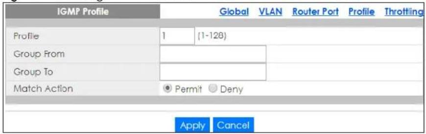
The following table describes the labels in this screen.
Table 117 Configuration > Multicast > IGMP > Profile > Add or Edit
| LABEL DESCRIPTION | |
| IGMP Profile | |
| Profile | Enter the Profile index number. |
| Group From Enter | the profile start group IP address. |
| Group To Enter the | profile end group IP address. |
| Match Action | Select the action of the profile as to be Permit or Deny. |
| Apply | Click Apply to save the changes. |
| Cancel | Click Cancel to discard the changes. |
26.2.8 Throttling Settings
Use this screen to view the Throttling settings. Click Configuration > Multicast > IGMP > Throttling to open this screen.
Figure 186 Configuration > Multicast > IGMP > Throttling
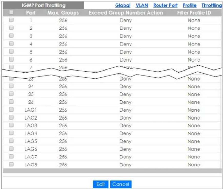
other
IGMP Port Throttling | Port | Max. Groups | Exceed Group Number Action | Filter Profile ID | |---|---|---|---| | 1 | 256 | Deny | None | | 2 | 256 | Deny | None | | 3 | 256 | Deny | None | | 4 | 256 | Deny | None | | 5 | 256 | Deny | None | | 6 | 256 | Deny | None | | 7 | 256 | Deny | None | | 23 | 256 | Deny | None | | 24 | 256 | Deny | None | | 25 | 256 | Deny | None | | 26 | 256 | Deny | None | | LAG1 | 256 | Deny | None | | LAG2 | 256 | Deny | None | | LAG3 | 256 | Deny | None | | LAG4 | 256 | Deny | None | | LAG5 | 256 | Deny | None | | LAG6 | 256 | Deny | None | | LAG7 | 256 | Deny | None | | LAG8 | 256 | Deny | None | Edit CancelThe following table describes the labels in this screen.
Table 118 Configuration > Multicast > IGMP > Throttling
| LABEL DESCRIPTION | |
| IGMP Port Throttling | |
| Port Displays the port index value. | |
| Max. Groups Displays the maximum number of groups. | |
| Exceed Group Number Action | Displays the action taken by the groups asPermit or Deny. |
| Filter Profile ID Displays the throttling filter profile ID. | |
| Edit | Select this check box to configure the properties of a port. Click theEditbutton change the properties of the port. |
| Cancel | Click Cancelto discard the changes. |
26.2.9 Edit Throttling
Use this screen to configure the Throttling settings. Click Configuration > Multicast > IGMP > Throttling > Edit to open this screen.
Figure 187 Configuration > Multicast > IGMP > Throttling > Edit
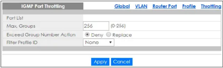
The following table describes the labels in this screen.
Table 119 Configuration > Multicast > IGMP > Throttling > Edit
| LABEL DESCRIPTION | |
| IGMP Port Throttling | |
| Port List Enter the port index values. | |
| Max. Groups Enter the maximum number of groups. Enter a value between 0 and 256. | |
| Exceed Group Number Action | Select the action taken by the groups to be Deny or Replace. |
| Filter Profile ID Select the throttling filter profile ID from the dropdown list. | |
| Apply | Click Apply to save the changes. |
| Cancel | Click Cancel to discard the changes. |
CHAPTER 27
Configuration: Spanning Tree
27.1 Overview
This section provides information for Spanning Tree in Configuration.
The Switch supports Spanning Tree Protocol (STP), Rapid Spanning Tree Protocol (RSTP) and Multiple Spanning Tree Protocol (MSTP) as defined in the following standards.
• IEEE 802.1D Spanning Tree Protocol
- IEEE 802.1w Rapid Spanning Tree Protocol
- IEEE 802.1s Multiple Spanning Tree Protocol
The Switch also allows you to set up multiple STP configurations (or trees). Ports can then be assigned to the trees.
27.2 Spanning Tree
(R)STP detects and breaks network loops and provides backup links between switches, bridges or routers. It allows a switch to interact with other (R)STP-compliant switches in your network to ensure that only one path exists between any two stations on the network.
27.2.1 Global Settings
Use this screen to view the Global settings. Click Configuration > Spanning Tree > Global to open this screen.
Figure 188 Configuration > Spanning Tree > Global
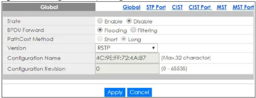
The following table describes the labels in this screen.
Table 120 Configuration > Spanning Tree > Global
| LABEL DESCRIPTION | |
| Global | |
| State | Select to Enable or Disable the Spanning-Tree function. |
| BPDU Forward | Select the bridge protocol data units forward (BPDU) option to be Flooding or Filtering. |
| Path Cost Method | Select Short or Long as a Path Cost method.Path cost is the cost of transmitting a frame on to a LAN through that port. It is recommended that you assign this value according to the speed of the bridge. The slower the media, the higher the cost. |
| Version | Select the type of spanning tree protocol to use. The following options are available:STPRSTPMSTP |
| Configuration Name | Enter the name of the configuration in hexadecimal. The maximum number characters is 32. |
| Configuration Revision | Enter the revision number of configuration. The number can be between 0 and 65535. |
| Apply | Click Apply to save the changes. |
| Cancel | Click Cancel to discard the changes. |
27.2.2 STP Port
Use this screen to view the STP Port settings. Click Configuration > Spanning Tree > STP Port to open this screen.
Figure 189 Configuration > Spanning Tree > STP Port
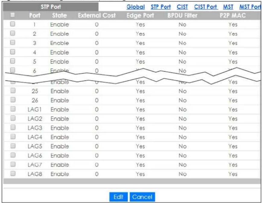
The following table describes the labels in this screen.
Table 121 Configuration > Spanning Tree > STP Port
| LABEL DESCRIPTION | |
| STP Port | |
| Port Displays the in | dex number of the STP port. |
| State Display the s | status of the STP port as enabled or disabled. |
| External Cost Dis | ays the external path cost. |
| Edge Port | Displays the edge port status as Yes or No. |
| BPDU Filter | Displays the BPDU filter status as Yes or No. |
| P2P MAC | Displays the P2P MAC status as Yes or No. |
| Edit | Select this check box to configure the properties of a port. Click the Edit button change the properties of the port. |
| Cancel | Click Cancel to discard the changes. |
27.2.3 STP Port Edit
Use this screen to configure the STP Port Edit settings. Click Configuration > Spanning Tree > STP Port > Edit to open this screen.
Figure 190 Configuration > Spanning Tree > STP Port > Edit
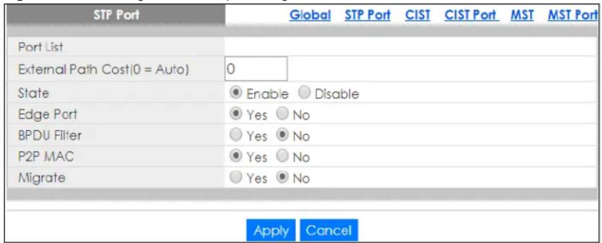
The following table describes the labels in this screen.
Table 122 Configuration > Spanning Tree > STP Port > Edit
| LABEL DESCRIPTION | |
| STP Port | |
| Port List Enter the index number of the STP ports. | |
| External Path Cost (0=Auto) | Enter the external path cost. Enter 0 for Auto. |
| State Select the state of the STP port as enabled or disabled. | |
| Edge Port | Select this check box to configure a port as an edge port when it is directly attached to a computer. An edge port changes its initial STP port state from blocking state to forwarding state immediately without going through listening and learning states right after the port is configured as an edge port or when its link status changes.Note: An edge port becomes a non-edge port as soon as it receives a Bridge Protocol Data Unit (BPDU). |
| BPDU Filter | Select Yes to activate BPDU filter or No to deactivate it. |
| P2P MAC | Select Yes to activate P2P MAC or No to deactivate it. |
| Migrate | Select Yes to activate Migrate or No to deactivate it. |
| Apply | Click Apply to save the changes. |
| Cancel | Click Cancel to discard the changes. |
27.2.4 CIST Settings
Use this screen to view the CIST settings. Click Configuration > Spanning Tree > CIST to open this screen.
Figure 191 Configuration > Spanning Tree > CIST
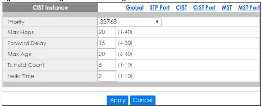
The following table describes the labels in this screen.
Table 123 Configuration > Spanning Tree > CIST
| LABEL DESCRIPTION | |
| CIST Instance | |
| Priority Configure | priority of CIST bridge ID.Priority is part of bridge ID, used for CIST root bridge selection. |
| Max Hops Enter a | maximum number of hops value. The value can be between 1 and 40. |
| Forward Delay | This is the maximum time (in seconds) a switch will wait before changing states. This delay is required because every switch must receive information about topology changes before it starts to forward frames. In addition, each port needs time to listen for conflicting information that would make it return to a blocking state; otherwise, temporary data loops might result. The allowed range is 4 to 30 seconds.As a general rule:2 * (Forward Delay - 1) >= Max Age >= 2 * (Hello Time + 1) |
| Max Age | This is the maximum time (in seconds) a switch can wait without receiving a BPDU before attempting to reconfigure. All switch ports (except for designated ports) should receive BPDUs at regular intervals. Any port that ages out STP information (provided in the last BPDU) becomes the designated port for the attached LAN. If it is a root port, a new root port is selected from among the switch ports attached to the network. The allowed range is 6 to 40 seconds. |
| Tx Hold Count Enter a transmission hold count value. The value can be between 1 and 10. | |
| Hello Time | This is the time interval in seconds between BPDU (Bridge Protocol Data Units) configuration message generations by the root switch. The allowed range is 1 to 10 seconds. |
| Apply | Click Apply to save the changes. |
| Cancel | Click Cancel to discard the changes. |
27.2.5 CIST Port
Use this screen to view the CIST Port settings. Click Configuration > Spanning Tree > CIST Port to open this screen.
Figure 192 Configuration > Spanning Tree > CIST Port
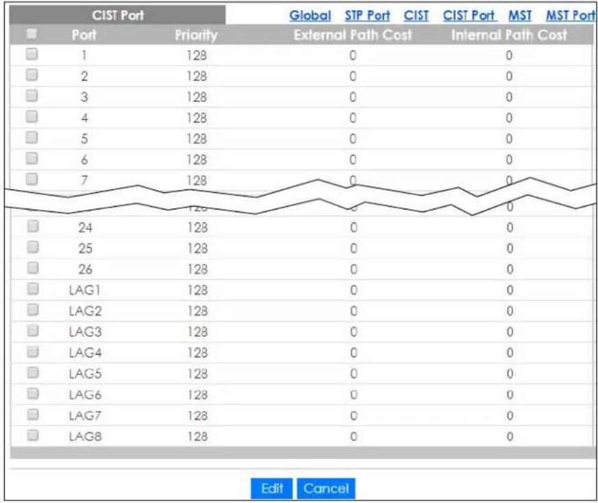
line
| Port | Priority | Global | STP Port | CIST | CIST Port | MST | MST Port | |---|---|---|---|---|---|---|---| | 1 | 128 | 0 | 0 | 0 | 0 | 0 | 0 | | 2 | 128 | 0 | 0 | 0 | 0 | 0 | 0 | | 3 | 128 | 0 | 0 | 0 | 0 | 0 | 0 | | 4 | 128 | 0 | 0 | 0 | 0 | 0 | 0 | | 5 | 128 | 0 | 0 | 0 | 0 | 0 | 0 | | 6 | 128 | 0 | 0 | 0 | 0 | 0 | 0 | | 7 | 128 | 0 | 0 | 0 | 0 | 0 | 0 | | 24 | 128 | 0 | 0 | 0 | 0 | 0 | 0 | | 25 | 128 | 0 | 0 | 0 | 0 | 0 | 0 | | 26 | 128 | 0 | 0 | 0 | 0 | 0 | 0 | | LAG1 | 128 | 0 | 0 | 0 | 0 | 0 | 0 | | LAG2 | 128 | 0 | 0 | 0 | 0 | 0 | 0 | | LAG3 | 128 | 0 | 0 | 0 | 0 | 0 | 0 | | LAG4 | 128 | 0 | 0 | 0 | 0 | 0 | 0 | | LAG5 | 128 | 0 | 0 | 0 | 0 | 0 | 0 | | LAG6 | 128 | 0 | 0 | 0 | 0 | 0 | 0 | | LAG7 | 128 | 0 | 0 | 0 | 0 | 0 | 0 | | LAG8 | 128 | 0 | 0 | 0 | 0 | 0 | 0 | Edit CancelThe following table describes the labels in this screen.
Table 124 Configuration > Spanning Tree > CIST Port
| LABEL DESCRIPTION | |
| CIST Port | |
| Port Displays the in | dex number of the STP port. |
| Priority Displays the | priority for each port here. |
| External Path Cost | Displays the external path cost. |
| Internal Path Cost | Displays the internal path cost. |
| Edit | Select this check box to configure the properties of a port. Click the Edit button change the properties of the port. |
| Cancel | Click Cancel to discard the changes. |
27.2.6 CIST Port Edit
Use this screen to configure the CIST Port Edit settings. Click Configuration > Spanning Tree > CIST Port > Edit to open this screen.
Figure 193 Configuration > Spanning Tree > CIST Port > Edit
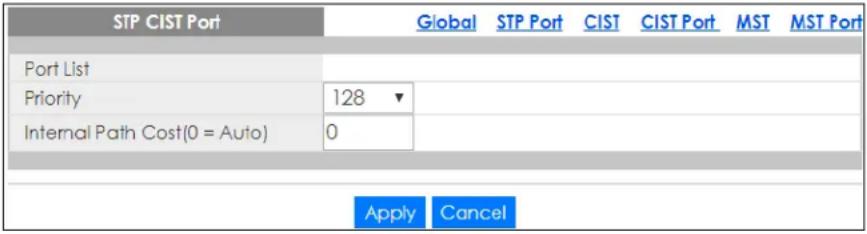
The following table describes the labels in this screen.
Table 125 Configuration > Spanning Tree > CIST Port > Edit
| LABEL DESCRIPTION | |
| STP CIST Port | |
| Port List Enter the index number of the STP ports. | |
| Priority Configure the priority for each port here. | |
| Internal Path Cost (0=Auto) | Enter the internal path cost. Enter 0 or Auto. |
| Apply | Click Apply to save the changes. |
| Cancel | Click Cancel to discard the changes. |
27.2.7 MST Settings
Use this screen to view the MST settings. Click Configuration > Spanning Tree > MST to open this screen.
Figure 194 Configuration > Spanning Tree > MST

The following table describes the labels in this screen.
Table 126 Configuration > Spanning Tree > MST
| LABEL DESCRIPTION | |
| MST Instance | |
| MSTI | This displays the Multiple Spanning Tree Instances (MSTI). |
| VLAN List This displays a list of MSTI VLANs. | |
| VLAN Count This displays the VLAN count. | |
| Priority This displays the priority for each port here. | |
| Action | |
| Edit | Click Edit to make changes to the entry. |
| Delete | Click Delete to remove the entry. |
| Add | Click Add to create a new MST Instance entry. |
27.2.8 Add or Edit MST
Use this screen to configure the MST settings. Click Configuration > Spanning Tree > MST > Add or Edit to open this screen.
Figure 195 Configuration > Spanning Tree > MST > Add or Edit
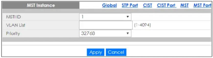
The following table describes the labels in this screen.
Table 127 Configuration > Spanning Tree > MST > Add or Edit
| LABEL DESCRIPTION | |
| MST Instance | |
| MST ID Select a Multiple Spanning Tree Instance (MSTI) ID. | |
| VLAN List Enter a MSTI VLAN ID | |
| Priority Select a MSTI bridge ID priority value. | |
| Apply | ClickApplyto save the changes. |
| Cancel | ClickCancelto discard the changes. |
27.2.9 MST Port Settings
Use this screen to view the MST Port settings. Click Configuration > Spanning Tree > MST Port to open this screen.
Figure 196 Configuration > Spanning Tree > MST Port
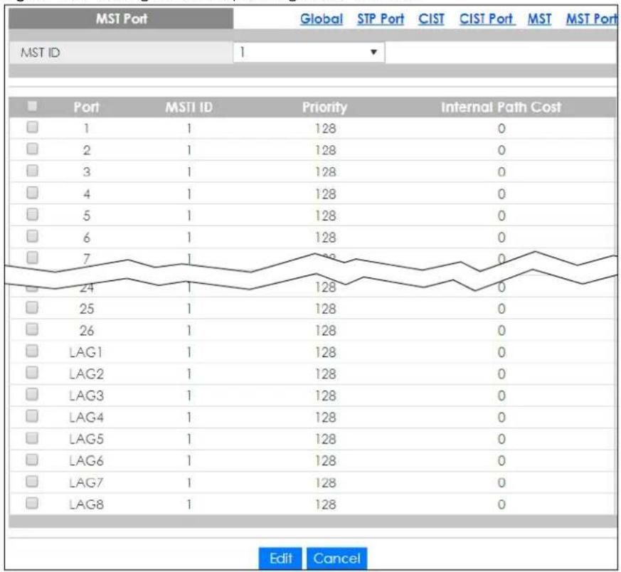
line
| Port | MST ID | Priority | Internal Path Cost | |---|---|---|---| | 1 | 1 | 128 | 0 | | 2 | 1 | 128 | 0 | | 3 | 1 | 128 | 0 | | 4 | 1 | 128 | 0 | | 5 | 1 | 128 | 0 | | 6 | 1 | 128 | 0 | | 7 | 1 | 128 | 0 | | 24 | 1 | 128 | 0 | | 25 | 1 | 128 | 0 | | 26 | 1 | 128 | 0 | | LAG1 | 1 | 128 | 0 | | LAG2 | 1 | 128 | 0 | | LAG3 | 1 | 128 | 0 | | LAG4 | 1 | 128 | 0 | | LAG5 | 1 | 128 | 0 | | LAG6 | 1 | 128 | 0 | | LAG7 | 1 | 128 | 0 | | LAG8 | 1 | 128 | 0 | Edit CancelThe following table describes the labels in this screen.
Table 128 Configuration > Spanning Tree > MST Port
| LABEL DESCRIPTION | |
| MST Port | |
| MST ID Select the MST port ID number from the dropdown list. | |
| Port This displays the index number of the MST port. | |
| MSTI ID This displays the index value of the MSTI. | |
| Priority This displays the priority for each port. | |
| Internal Path Cost | This displays the internal path cost. |
| Edit | Select this check box to configure the properties of a port. Click the Edit button change the properties of the port. |
| Cancel | Click Cancel to discard the changes. |
27.2.10 MST Port Edit
Use this screen to configure the MST Port Edit settings. Click Configuration > Spanning Tree > MST Port > Edit to open this screen.
Figure 197 Configuration > Spanning Tree > MST Port > Edit
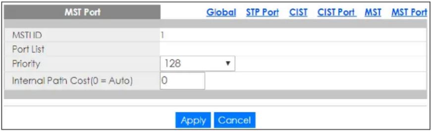
The following table describes the labels in this screen.
Table 129 Configuration > Spanning Tree > MST Port > Edit
| LABEL DESCRIPTION | |
| STP MST Port | |
| MST ID This displays the MST ID number. | |
| Port List Enter the index number of the MTP ports. | |
| Priority Configure the priority for each port here. | |
| Internal Path Cost (0=Auto) | Enter the internal path cost. Enter 0 for Auto. |
| Apply | Click Apply to save the changes. |
| Cancel | Click Cancel to discard the changes. |
CHAPTER 28
Configuration: LLDP
28.1 Overview
This section provides information for LLDP in Configuration.
Use the Link Layer Discovery Protocol (LLDP) screens to configure LLDP Switch settings.
28.2 LLDP Settings
This page allows the user to inspect and configure the current LLDP port settings.
28.2.1 Global Settings
Use this screen to configure the Global settings. Click Configuration > LLDP > Global to open this screen.
Figure 198 Configuration > LLDP > Global
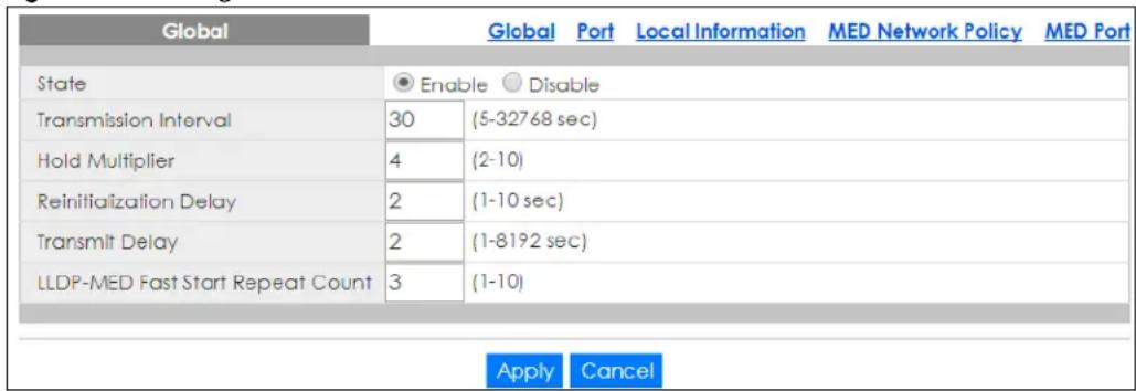
The following table describes the labels in this screen.
Table 130 Configuration > LLDP > Global
| LABEL DESCRIPTION | |
| Global | |
| State | Select Enable to activate the global LLDP. |
| Transmission Interval | Enter the transmission interval value.The switch periodically transmits LLDP frames to its neighbors for having the network discovery information up-to-date. The interval between each LLDP frame is determined by the Tx Interval value. Valid values are restricted to 5 – 32768 seconds. |
| Hold Multiplier Enter the hold multiplier value.Each LLDP frame contains information about how long the information in the LLDP frame shall be considered valid. The LLDP information valid period is set to Tx Hold multiplied by Tx Interval seconds. Valid values are restricted to 2 – 10 times. | |
| Reinitialization Delay | Enter the re-initialization delay value.When a port is disabled, LLDP is disabled or the switch is rebooted, an LLDP shutdown frame is transmitted to the neighboring units, signaling that the LLDP information is not valid anymore. Tx Reinit controls the amount of seconds between the shutdown frame and a new LLDP initialization. Valid values are restricted to 1 – 10 seconds. |
| Transmit Delay Enter the transmission delay value.If some configuration is changed (for example, the IP address) a new LLDP frame is transmitted, but the time between the LLDP frames will always be at least the value of Tx Delay seconds. Tx Delay cannot be larger than 1/4 of the Tx Interval value. Valid values are restricted to 1 – 8192 seconds. | |
| LLDP-MED Fast Start Repeat Count | Enter the LLDP-MED fast start repeat count value.Because there is a risk of an LLDP frame being lost during transmission between neighbors, it is recommended to repeat the fast start transmission multiple times to increase the possibility of the neighbors receiving the LLDP frame. With Fast start repeat count it is possible to specify the number of times the fast start transmission would be repeated. The recommended value is four times, given that four LLDP frames with a 1 second interval will be transmitted, when an LLDP frame with new information is received. |
| Apply | Click Apply to save the changes. |
| Cancel | Click Cancel to discard the changes. |
28.2.2 Port Settings
Use this screen to view the Port settings. Click Configuration > LLDP > Port to open this screen.
Figure 199 Configuration > LLDP > Port
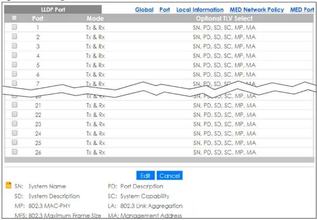
The following table describes the labels in this screen.
Table 131 Configuration > LLDP > Port
| LABEL DESCRIPTION | |
| LLDP VLAN | |
| Port Displays the index number of the LLDP port. | |
| Mode | Displays the mode of the LLDP port as Disable, Tx Only, Rx Only, or Tx & Rx. |
| Optional TLV Select | Displays the TLV as one or more of the following options:• SN – System Name• PD – Port Description• SD – System Description• SC – System Capability• MP – 802.3 MAC-PHY• LA – 802.3 Link Aggregation• MFS – 802.3 Maximum Frame Size• MA – Management Address |
| Edit | Select this check box to configure the properties of a port. Click the Edit button change the properties of the port. |
| Cancel | Click Cancel to discard the changes. |
28.2.3 Port Edit
Use this screen to configure the Port Edit settings. Click Configuration > LLDP > Port > Edit to open this screen.
Figure 200 Configuration > LLDP > Port > Edit
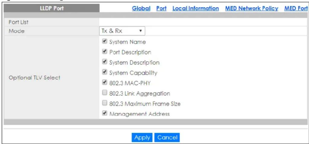
The following table describes the labels in this screen.
Table 132 Configuration > LLDP > Port > Edit
| LABEL DESCRIPTION | |
| LLDP Port | |
| Port List Displays the index number of the LLDP ports. | |
| Mode | Select the mode of the LLDP port as Disable, Tx Only, Rx Only, or Tx & Rx. |
| Optional TLV Select | Select the TLV as one or more of the following options:SN – System NamePD – Port DescriptionSD – System DescriptionSC – System CapabilityMP – 802.3 MAC-PHYLA – 802.3 Link AggregationMFS – 802.3 Maximum Frame SizeMA – Management Address |
| Apply | Click Apply to save the changes. |
| Cancel | Click Cancel to discard the changes. |
28.2.4 Local Information Settings
Use this screen to view the Local Information settings. Click Configuration > LLDP > Local Information to open this screen.
Figure 201 Configuration > LLDP > Local Information
| Local Information | Global Port Local Information MED Network Policy MED Port | ||||
| Chassis ID Subtype | MAC Address | ||||
| Chassis ID | 4C:9E:FF:72:4A:87 | ||||
| System Name | GS1900 | ||||
| System Description | GS1900-24HP | ||||
| Capabilities Supported | Bridge | ||||
| Capabilities Enable | Bridge | ||||
| Port ID Subtype | Interface name | ||||
| MED Part Location | |||||
| Port Coordinate Civic Address ECS ELIN | |||||
| 1 | Latitude:0.0000 North, Longitude:0.0000 East, Altitude:0.0000, Map Datum: | --- | --- | ||
| 2 | Latitude:0.0000 North, Longitude:0.0000 East, Altitude:0.0000, Map Datum: | --- | --- | ||
| 3 | Latitude:0.0000 North, Longitude:0.0000 East, Altitude:0.0000, Map Datum: | --- | --- | ||
| 4 | Latitude:0.0000 North, Longitude:0.0000 East, Altitude:0.0000, Map Datum: | --- | --- | ||
| 5 | Latitude:0.0000 North, Longitude:0.0000 East, Altitude:0.0000, Map Datum: | --- | --- | ||
| 22 | Latitude:0.0000 North, Longitude:0.0000 East, Altitude:0.0000, Map Datum: | --- | --- | ||
| 23 | Latitude:0.0000 North, Longitude:0.0000 East, Altitude:0.0000, Map Datum: | --- | --- | ||
| 24 | Latitude:0.0000 North, Longitude:0.0000 East, Altitude:0.0000, Map Datum: | --- | --- | ||
| 25 | Latitude:0.0000 North, Longitude:0.0000 East, Altitude:0.0000, Map Datum: | --- | --- | ||
| 26 | Latitude:0.0000 North, Longitude:0.0000 East, Altitude:0.0000, Map Datum: | --- | --- | ||
The following table describes the labels in this screen.
Table 133 Configuration > LLDP > Local Information
| LABEL DESCRIPTION | |
| Local Information | |
| Chassis ID Subtype | Displays the chassis ID subtype. |
| Chassis ID | The Chassis ID is the identification of the neighbor's LLDP frames. |
| System Name | System Name is the name advertised by the neighbor unit. |
| System Description | Displays the System Description. |
| Capabilities Supported | Capabilities Supported describes the neighbor unit's capabilities. The possible capabilities are:1. Other2. Repeater3. Bridge4. WLAN Access Point5. Router6. Telephone7. DOCSIS cable device8. Station only9. ReservedWhen a capability is enabled, the capability is followed by (+). If the capability is disabled, the capability is followed by (-). |
| Capabilities Enable | Displays which capability is enabled. |
| Port ID Subtype Displays the Port ID Subtype. | |
| MED Port Location | |
| Port Displays the index number of the LLDP ports. | |
| Coordinate Displays the location coordinate of the LLDP ports. | |
| Civic Address Displays the location of the civic addresses in hexadecimal. | |
| ECS ELIN Emergency Call Service (for example, E911 and others), such as defined by TIA or NENA.Emergency Call Service ELIN identifier data format is defined to carry the ELIN identifier as used during emergency call setup to a traditional CAMA or ISDN trunk-based PSAP. This format consists of a numerical digit string, corresponding to the ELIN to be used for emergency calling. | |
| Edit | Select this check box to configure the properties of a port. Click the Edit button change the properties of the port. |
| Cancel | Click Cancel to discard the changes. |
28.2.5 Local Information Edit
Use this screen to configure the Port Edit settings. Click Configuration > LLDP > Local Information > Edit to open this screen.
Figure 202 Configuration > LLDP > Local Information > Edit
| MED Port Location | Global Port Local Information MED Network Policy MED Port | ||
| Port List | |||
| Location Coordinate | Latitude 0.0000° North ▼ | ||
| Longitude 0.0000° East ▼ | |||
| Altitude 0.0000 Meters ▼ | |||
| MapDatum WGS84 ▼ | |||
| Location Civic Address | Country code | ||
| State | |||
| Country | |||
| City | |||
| City district | |||
| Block (Neighbourhood) | |||
| Street | |||
| Leading street direction | |||
| Trailing street suffix | |||
| Street suffix | |||
| House no. | |||
| House no. suffix | |||
| Landmark | |||
| Additional location info | |||
| Name | |||
| Zip code | |||
| Building | |||
| Apartment | |||
| Floor | |||
| Room no. | |||
| Place type | |||
| Postal community name | |||
| P.O. Box | |||
| Location ECS ELIN | |||
The following table describes the labels in this screen.
Table 134 Configuration > LLDP > Local Information > Edit
| LABEL DESCRIPTION | |
| MED Port Location | |
| Port List | Displays the index number of the LLDP ports. The value is made of 16 pairs of hexadecimal characters. |
| Location Coordinates | |
| Latitude | Latitude SHOULD be normalized to within 0 – 90 degrees with a maximum of four digits.It is possible to specify the direction to either North of the equator or South of the equator. |
| Longitude | Longitude SHOULD be normalized to within 0 – 180 degrees with a maximum of four digits.It is possible to specify the direction to either East of the prime meridian or West of the prime meridian. |
| Altitude | Altitude SHOULD be normalized to within -32767 to 32767 with a maximum of four digits.It is possible to select between two altitude types (floors or meters).Meters: Representing meters of Altitude defined by the vertical datum specified.Floors: Representing altitude in a form more relevant in buildings which have different floor-to-floor dimensions. An altitude = 0.0 is meaningful even outside a building, and represents ground level at the given latitude and longitude. Inside a building, 0.0 represents the floor level associated with ground level at the main entrance. |
| Map Datum | The Map Datum is used for the coordinates given in these options:WGS84: (Geographical 3D) – World Geodesic System 1984, CRS Code 4327, Prime Meridian Name: Greenwich.NAD83/NAVD88: North American Datum 1983, CRS Code 4269, Prime Meridian Name: Greenwich; The associated vertical datum is the North American Vertical Datum of 1988 (NAVD88). This datum pair is to be used when referencing locations on land, not near tidal water (which would use Datum = NAD83/MLLW).NAD83/MLLW: North American Datum 1983, CRS Code 4269, Prime Meridian Name: Greenwich; The associated vertical datum is Mean Lower Low Water (MLLW). This datum pair is to be used when referencing locations on water/sea/ocean. |
| Location Civic Address | IETF Geopriv Civic Address based Location Configuration Information (Civic Address LCI).Country code: The two-letter ISO 3166 country code in capital ASCII letters – Example: DK, DE or US.State: National subdivisions (state, canton, region, province, prefecture).County: County, parish, gun (Japan), district.City: City, township, shi (Japan) – Example: Copenhagen.City district: City division, borough, city district, ward, chou (Japan).Block (Neighborhood): Neighborhood, block.Street: Street – Example: Poppelvej.Leading street direction: Leading street direction – Example: N.Trailing street suffix: Trailing street suffix – Example: SW.Street suffix: Street suffix - Example: Ave, Platz.House no.: House number – Example: 21.House no. suffix: House number suffix – Example: A, 1/2.Landmark: Landmark or vanity address – Example: Columbia University.Additional location info: Additional location info – Example: South Wing.Name: Name (residence and office occupant) – Example: Flemming Jahn.Zip code: Postal/zip code – Example: 2791.Building: Building (structure) – Example: Low Library.Apartment: Unit (Apartment, suite) – Example: Apt 42.Floor: Floor – Example: 4.Room no.: Room number – Example: 450F.Place type: Place type – Example: Office.Postal community name: Postal community name – Example: Leonia.P.O. Box: Post office box (P.O. BOX) – Example: 12345. |
| Location ECS ELIN | Emergency Call Service (for example, E911 and others), such as defined by TIA or NENA.Emergency Call Service ELIN identifier data format is defined to carry the ELIN identifier as used during emergency call setup to a traditional CAMA or ISDN trunk-based PSAP. This format consists of a numerical digit string, corresponding to the ELIN to be used for emergency calling. |
| Apply | Click Apply to save the changes. |
| Cancel | Click Cancel to discard the changes. |
28.2.6 MED Network Policy
Use this screen to view the MED Network Policy settings. Click Configuration > LLDP > MED Network Policy to open this screen.
Figure 203 Configuration > LLDP > MED Network Policy

The following table describes the labels in this screen.
Table 135 Configuration > LLDP > MED Network Policy
| LABEL DESCRIPTION | |
| Network Policy Configuration | |
| No. Displays index | of network policy. |
| Application | Displays the Application type indicating the primary function of the applications. |
| VLAN ID Displays the VLAN ID (VID) for the port as defined in IEEE 802.1Q-2003. | |
| VLAN Tag | Displays the VLAN Tag value as Tagged or Untagged. |
| L2 Priority Displays the L2 priority layer value. | |
| DSCP Value Displays the DSCP Value. | |
| Action | |
| Edit | Click Edit to make changes to the entry. |
| Delete | Click Delete to remove the entry. |
| Add | Click Add to create a new Network Policy Configuration entry. |
28.2.7 MED Network Policy Add or Edit
Use this screen to configure the Port Edit settings. Click Configuration > LLDP > MED Network Policy > Add or Edit to open this screen.
Figure 204 Configuration > LLDP > MED Network Policy > Add or Edit
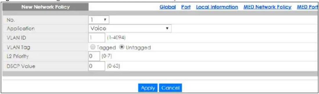
The following table describes the labels in this screen.
Table 136 Configuration > LLDP > MED Network Policy > Add or Edit
| LABEL DESCRIPTION | |
| New Network Policy | |
| No. Select the index of network policy | |
| Application | Select the Application type indicating the primary function of the applications defined for this network policy, advertised by an Endpoint or Network Connectivity Device. The possible application types are shown below.1. Voice – for use by dedicated IP Telephony handsets and other similar appliances supporting interactive voice services. These devices are typically deployed on a separate VLAN for ease of deployment and enhanced security by isolation from data applications.2. Voice Signaling – for use in network topologies that require a different policy for the voice signaling than for the voice media.3. Guest Voice – to support a separate limited feature-set voice service for guest users and visitors with their own IP Telephony handsets and other similar appliances supporting interactive voice services.4. Guest Voice Signaling – for use in network topologies that require a different policy for the guest voice signaling than for the guest voice media.5. Softphone Voice – for use by softphone applications on typical data centric devices, such as PCs or laptops.6. Video Conferencing – for use by dedicated Video Conferencing equipment and other similar appliances supporting real-time interactive video or audio services.7. Streaming Video – for use by broadcast or multicast based video content distribution and other similar applications supporting streaming video services that require specific network policy treatment. Video applications relying on TCP with buffering would not be an intended use of this application type.8. Video Signaling – for use in network topologies that require a separate policy for the video signaling than for the video media. |
| VLAN ID | Enter the VLAN ID (VID) for the port as defined in IEEE 802.1Q-2003. A value of 1 through 4094 is used to define a valid VLAN ID. A value of 0 (Priority Tagged) is used if the device is using priority tagged frames as defined by IEEE 802.1Q-2003, meaning that only the IEEE 802.1D priority level is significant and the default PVID of the ingress port is used instead. |
| VLAN Tag | TAG is indicative of whether the specified application type is using a tagged or an untagged VLAN. Select Tagged or Untagged.Untagged: The device is using an untagged frame format and as such does not include a tag header as defined by IEEE 802.1Q-2003.Tagged: The device is using the IEEE 802.1Q tagged frame format. |
| L2 Priority | Priority is the Layer 2 priority to be used for the specified application type. One of the eight priority levels (0 through 7). |
| DSCP Value | DSCP is the DSCP value to be used to provide Diffserv node behavior for the specified application type as defined in IETF RFC 2474. Contain one of 64 code point values (0 through 63). |
| Apply | Click Apply to save the changes. |
| Cancel | Click Cancel to discard the changes. |
28.2.8 MED Port
Use this screen to view the MED Port settings. Click Configuration > LLDP > MED Port to open this screen.
Figure 205 Configuration > LLDP > MED Port
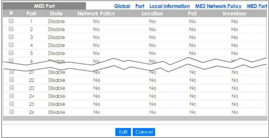
The following table describes the labels in this screen.
Table 137 Configuration > LLDP > MED Port
| LABEL DESCRIPTION | |
| MED Port | |
| Port | Displays the MED Port value. |
| State | Displays the state of the MED port as Enable or Disable. |
| Network Policy | Displays the Network Policy value. |
| Location Displays the Location value. | |
| PoE Displays the PoE value. | |
| Inventory Displays the Inventory value. | |
| Edit | Select this check box to configure the properties of a port. Click the Edit button change the properties of the port. |
| Cancel | Click Cancel to discard the changes. |
28.2.9 MED Port Edit
Use this screen to configure the MED Port Edit settings. Click Configuration > LLDP > MED Port > Edit to open this screen.
Figure 206 Configuration > LLDP > MED Port > Edit
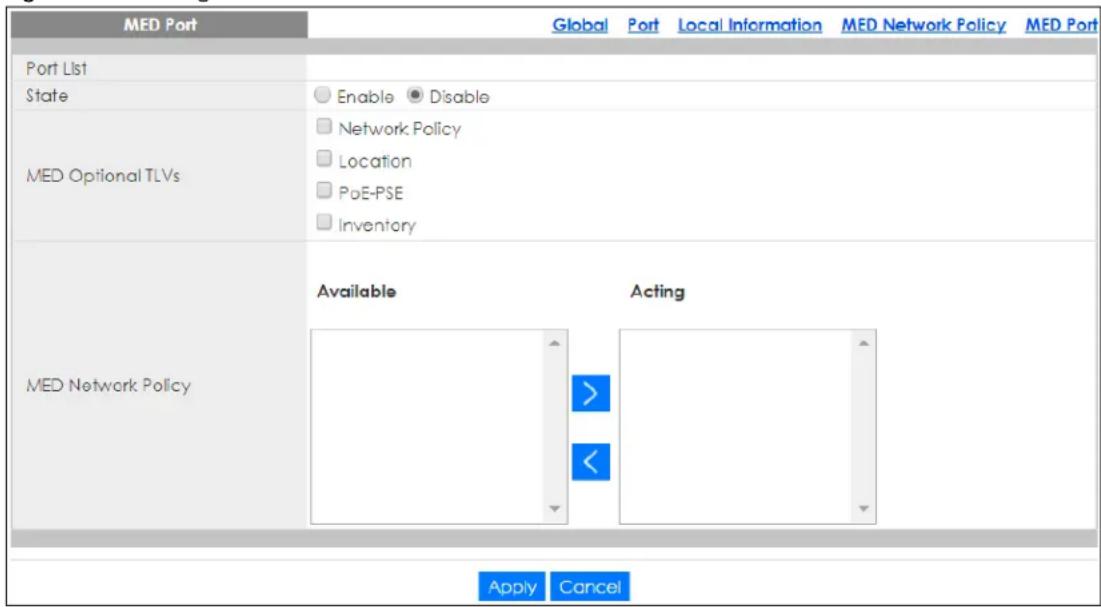
The following table describes the labels in this screen.
Table 138 Configuration > LLDP > MED Port > Edit
| LABEL DESCRIPTION | |
| MED Port | |
| Port List | Displays the Port List. |
| State Select Enable to activate the MED Port feature. | |
| MED Optional TLVs | Select one or more of the MED Optional TLVs:Network PolicyLocationPo EPSEIn v e n t o ry |
| MED Network Policy | Select one or more of the MED Network Policies in Available and move them to Acting to activate. |
| Apply | Click Apply to save the changes. |
| Cancel | Click Cancel to discard the changes. |
CHAPTER 29
Configuration: QoS
29.1 Overview
This section provides information for QoS (Quality of Service) in Configuration.
29.2 General Settings
Quality of Service (QoS) refers to both a network's ability to deliver data with minimum delay, and the networking methods used to control the use of bandwidth. Without QoS, all traffic data is equally likely to be dropped when the network is congested. This can cause a reduction in network performance and make the network inadequate for time-critical application such as video-on-demand.
29.2.1 Port Settings
Use this screen to view the Port settings. Click Configuration > QoS > General > Port to open this screen.
Figure 207 Configuration > QoS > General > Port
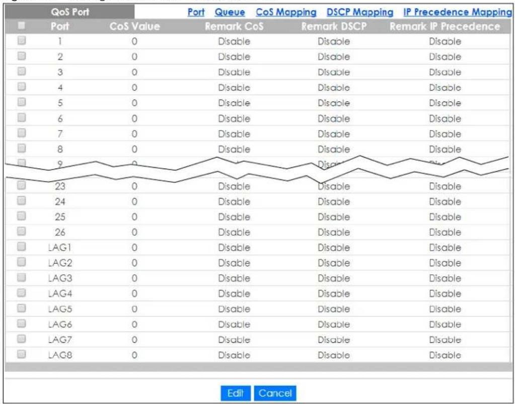
The following table describes the labels in this screen.
Table 139 Configuration > QoS > General > Port
| LABEL DESCRIPTION | |
| QoS Port | |
| Port Displays the QoS port list. | |
| CoS Value Displays the CoS value, range: 0 – 7. | |
| Remark CoS Displays if this function is disabled or enabled. | |
| Remark DSCP Displays if this function is disabled or enabled. | |
| Remark IP Precedence | Displays if this function is disabled or enabled. |
| Edit | Select this check box to configure the properties of a port. Click the Edit button change the properties of the port. |
| Cancel | Click Cancel to discard the changes. |
29.2.2 Port Edit
Use this screen to configure the Port Edit settings. Click Configuration > QoS > General > Port > Edit to open this screen.
Figure 208 Configuration > QoS > General > Port > Edit
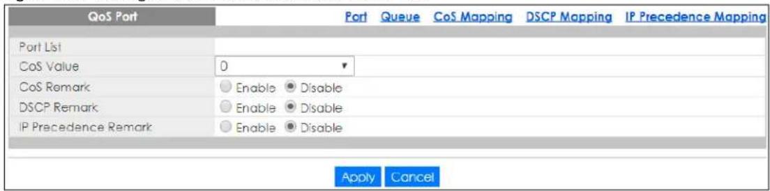
The following table describes the labels in this screen.
Table 140 Configuration > QoS > General > Port > Edit
| LABEL DESCRIPTION | |
| QoS Port | |
| Port List Displays the index number of the QoS ports. | |
| CoS Value | Select the CoS Value from the dropdown list. |
| CoS Remark Select | Enable to activate CoS Remark. |
| DSCP Remark Select | Enable to activate DSCP Remark. |
| IP Precedence Remark | Select Enable to activate IP Precedence Remark. |
| Apply | Click Apply to save the changes. |
| Cancel | Click Cancel to discard the changes. |
29.2.3 Queue Settings
Use this screen to view the Queue settings. Click Configuration > QoS > General > Queue to open this screen.
Figure 209 Configuration > QoS > General > Queue
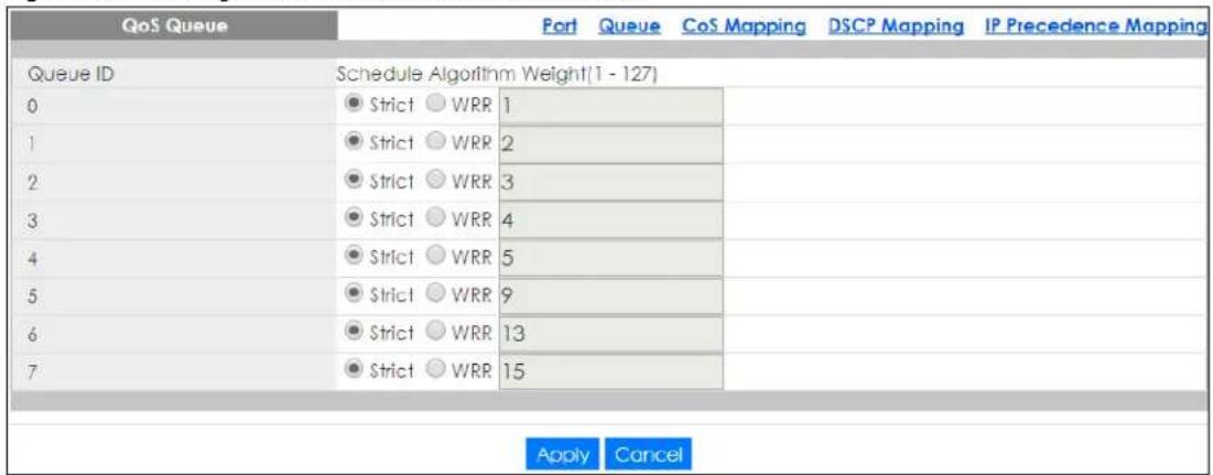
The following table describes the labels in this screen.
Table 141 Configuration > QoS > General > Queue
| LABEL DESCRIPTION | |
| QoS Queue | |
| Queue ID | Displays the Queue ID value. |
| Schedule Algorithm | Select the Schedule Algorithm as Strict or WRR. |
| Weight (1-127) Enter the weight of the QoS item. | |
| Apply | Click Apply to save the changes. |
| Cancel | Click Cancel to discard the changes. |
29.2.4 CoS Mapping
Use this screen to configure the CoS Mapping settings. Click Configuration > QoS > General > CoS Mapping to open this screen.
Figure 210 Configuration > QoS > General > CoS Mapping
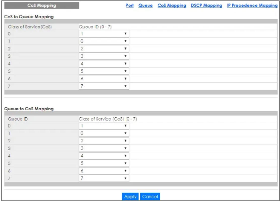
The following table describes the labels in this screen.
Table 142 Configuration > QoS > General > CoS Mapping
| LABEL DESCRIPTION | |
| CoS to Queue Mapping | |
| Class of Service (CoS) Displays a listing of the CoS, range: 0 – 7. | |
| Queue ID (0-7) Click the drop-down menu to map the CoS to a specific Queue ID. | |
| Queue to CoS Mapping | |
| Queue ID Displays a listing of the Queue ID, range: 0 – 7. | |
| Class of Service (CoS) (0–7) | Click the drop-down menu to map the Queue ID to a specific CoS. |
| Apply | ClickApplyto save the changes. |
| Cancel | Click Cancelto discard the changes. |
29.2.5 DSCP Mapping
Use this screen to configure the DSCP Mapping settings. Click Configuration > QoS > General > DSCP Mapping to open this screen.
Figure 211 Configuration > QoS > General > DSCP Mapping
| DSCP Mapping | Port | Queue | CoS Mapping | DSCP Mapping | IP Precedence Mapping | |||||
| DSCP to Queue Mapping | ||||||||||
| DSCP (0-7) | 0 | 0▼ | 1 | 0▼ | 2 | 0▼ | 3 | 0▼ | ||
| 4 | 0▼ | 5 | 0▼ | 6 | 0▼ | 7 | 0▼ | |||
| DSCP (8-15) | 8 | 1▼ | 9 | 1▼ | 10 | 1▼ | 11 | 1▼ | ||
| 12 | 1▼ | 13 | 1▼ | 14 | 1▼ | 15 | 1▼ | |||
| DSCP (16-23) | 16 | 2▼ | 17 | 2▼ | 18 | 2▼ | 19 | 2▼ | ||
| 20 | 2▼ | 21 | 2▼ | 22 | 2▼ | 23 | 2▼ | |||
| DSCP (24-31) | 24 | 3▼ | 25 | 3▼ | 26 | 3▼ | 27 | 3▼ | ||
| 28 | 3▼ | 29 | 3▼ | 30 | 3▼ | 31 | 3▼ | |||
| DSCP (32-39) | 32 | 4▼ | 33 | 4▼ | 34 | 4▼ | 35 | 4▼ | ||
| 36 | 4▼ | 37 | 4▼ | 38 | 4▼ | 39 | 4▼ | |||
| DSCP (40-47) | 40 | 5▼ | 41 | 5▼ | 42 | 5▼ | 43 | 5▼ | ||
| 44 | 5▼ | 45 | 5▼ | 46 | 5▼ | 47 | 5▼ | |||
| DSCP (48-55) | 48 | 6▼ | 49 | 6▼ | 50 | 6▼ | 51 | 6▼ | ||
| 52 | 6▼ | 53 | 6▼ | 54 | 6▼ | 55 | 6▼ | |||
| DSCP (56-63) | 56 | 7▼ | 57 | 7▼ | 58 | 7▼ | 59 | 7▼ | ||
| 60 | 7▼ | 61 | 7▼ | 62 | 7▼ | 63 | 7▼ | |||
The following table describes the labels in this screen.
Table 143 Configuration > QoS > General > DSCP Mapping
| LABEL DESCRIPTION | |
| DSCP Mapping | |
| DSCP to Queue Mapping | |
| Queue ID | Displays the DSCP Queue ID value. |
| Queue to DSCP Mapping | |
| DSCP (0-63) Select | the DSCP mapping value from the dropdown list. |
| Apply | Click Apply to save the changes. |
| Cancel | Click Cancel to discard the changes. |
Use this screen to configure the IP Precedence Mapping settings. Click Configuration > QoS > General > IP Precedence Mapping to open this screen.
Figure 212 Configuration > QoS > General > IP Precedence Mapping
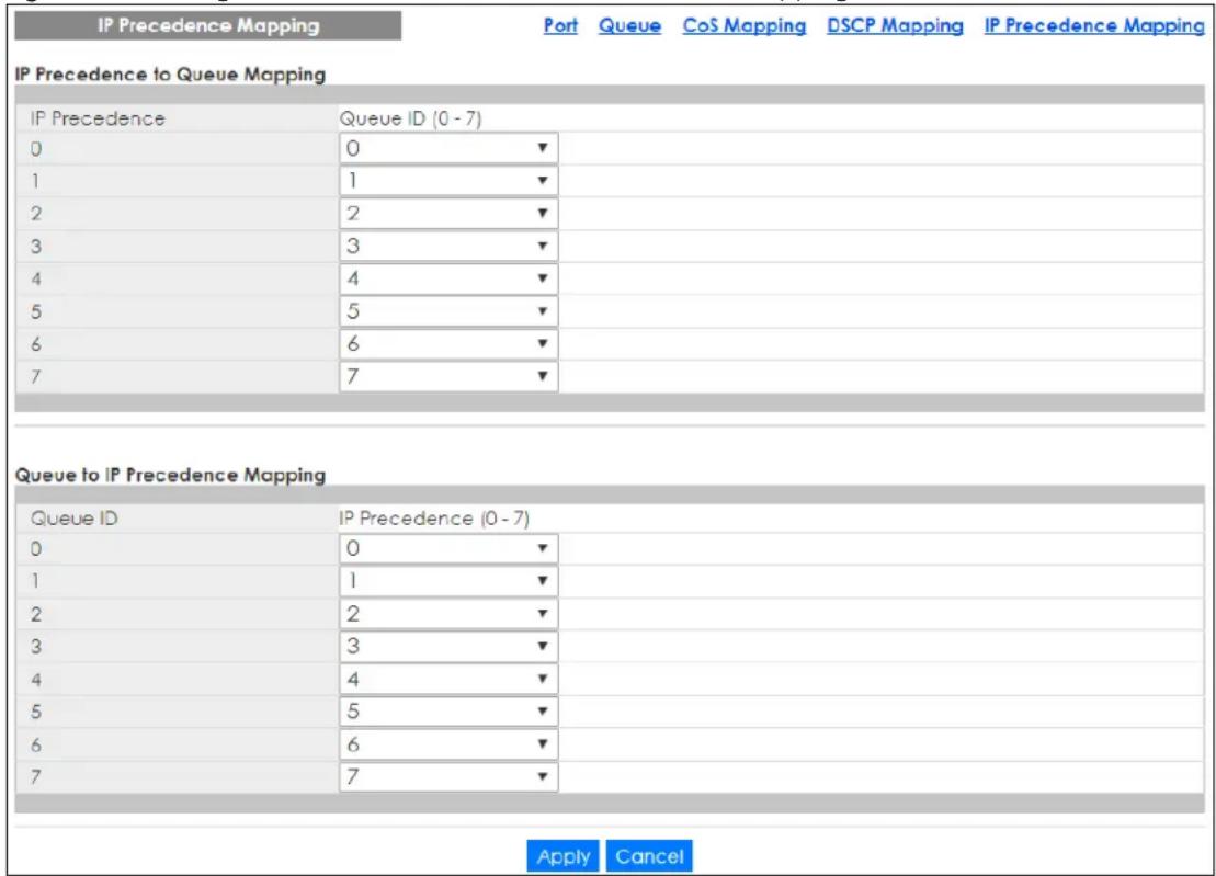
The following table describes the labels in this screen.
Table 144 Configuration > QoS > General > IP Precedence Mapping
| LABEL DESCRIPTION |
| IP Precedence Mapping |
| IP Precedence to Queue Mapping |
Table 144 Configuration > QoS > General > IP Precedence Mapping (continued)
| LABEL DESCRIPTION | |
| IP Precedence | Displays a listing of IP Precedence, range: 0 – 7. |
| Queue ID (0–7) | Click the drop-down menu to map an IP Precedence designation to a specific Queue ID (0 – 7). |
| Queue to IP Precedence Mapping | |
| Queue ID | Displays a listing of Queue ID, range: 0 – 7. |
| IP Precedence (0–7) | Click the drop-down menu to map a Queue ID to a specific IP precedence. |
| Apply | Click Apply to save the changes. |
| Cancel | Click Cancel to discard the changes. |
29.3 Trust Mode
29.3.1 Global Settings
Use this screen to view the Global settings. Click Configuration > QoS > Trust Mode > Global to open this screen.
Figure 213 Configuration > QoS > Trust Mode > Global

The following table describes the labels in this screen.
Table 145 Configuration > QoS > Trust Mode > Global
| LABEL DESCRIPTION | |
| Global | |
| Trust Mode | Select the Trust Mode from the dropdown list. |
| Apply | Click Apply to save the changes. |
| Cancel | Click Cancel to discard the changes. |
29.3.2 Port Settings
Use this screen to view the Port settings. Click Configuration > QoS > Trust Mode > Port to open this screen.
Figure 214 Configuration > QoS > Trust Mode > Port
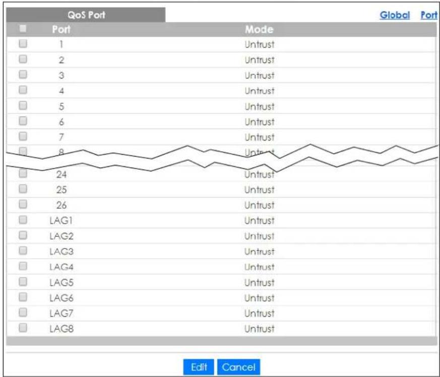
line
| Port | Mode | Value | |------|------------|-------| | 1 | Untrust | 1 | | 2 | Untrust | 2 | | 3 | Untrust | 3 | | 4 | Untrust | 4 | | 5 | Untrust | 5 | | 6 | Untrust | 6 | | 7 | Untrust | 7 | | 8 | Untrust | 8 | | 24 | Untrust | 24 | | 25 | Untrust | 25 | | 26 | Untrust | 26 | | LAG1 | Untrust | LAG1 | | LAG2 | Untrust | LAG2 | | LAG3 | Untrust | LAG3 | | LAG4 | Untrust | LAG4 | | LAG5 | Untrust | LAG5 | | LAG6 | Untrust | LAG6 | | LAG7 | Untrust | LAG7 | | LAG8 | Untrust | LAG8 |The following table describes the labels in this screen.
Table 146 Configuration > QoS > Trust Mode > Port
| LABEL DESCRIPTION | |
| QoS Port | |
| Port Displays the port index value. | |
| Mode | Displays the Trust status asTrustorUntrust. |
| Edit | Select this check box to configure the properties of a port. Click theEditbutton change the properties of the port. |
| Cancel | Click Cancelto discard the changes. |
29.3.3 Trust Mode Edit
Use this screen to configure the Trust Mode settings. Click Configuration > QoS > Trust Mode > Port > Edit to open this screen.
Figure 215 Configuration > QoS > Trust Mode > Port > Edit
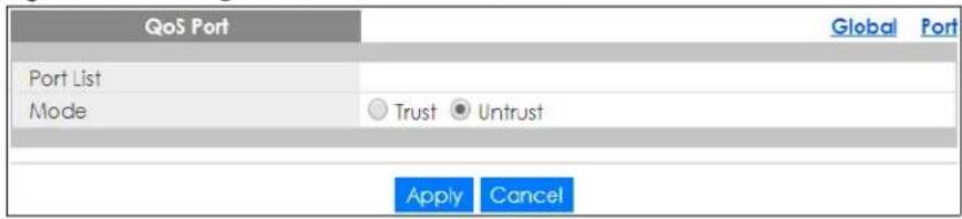
The following table describes the labels in this screen.
Table 147 Configuration > QoS > Trust Mode > Port > Edit
| LABEL DESCRIPTION | |
| QoS Port | |
| Port List Displays the port index values. | |
| Mode | Select the Trust Mode for the QoS port list as Trust or Untrust. |
| Apply | Click Apply to save the changes. |
| Cancel | Click Cancel to discard the changes. |
CHAPTER 30
Configuration: Security
30.1 Overview
This section provides information for Security in Configuration.
30.2 Port Security
30.2.1 Global Settings
Use this screen to view the Global settings. Click Configuration > Security > Port Security > Global to open this screen.
Figure 216 Configuration > Security > Port Security > Global

The following table describes the labels in this screen.
Table 148 Configuration > Security > Port Security > Global
| LABEL DESCRIPTION | |
| Global | |
| State | Select the global security setting to be enabled or disabled. |
| Apply | Click Apply to save the changes. |
| Cancel | Click Cancel to discard the changes. |
30.2.2 Port Settings
Use this screen to view the Port settings. Click Configuration > Security > Port Security > Port to open this screen.
Figure 217 Configuration > Security > Port Security > Port
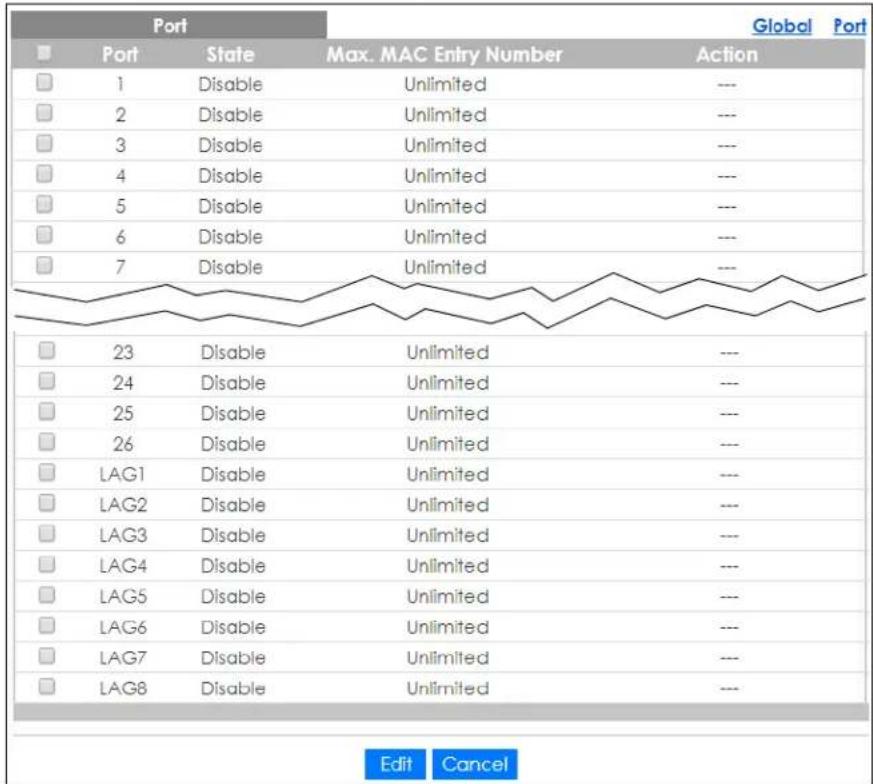
The following table describes the labels in this screen.
Table 149 Configuration > Security > Port Security > Port
| LABEL DESCRIPTION | |
| Port | |
| Port Displays the port index value. | |
| State | Displays the Trust status as Enable or Disable. |
| Max. MAC Entry Number | Displays the designated maximum number of allowed MAC entries. The maximum MAC entry number can be learned for individual ports. |
| Action | Displays the Action as Discard or Shutdown. |
| Edit | Select this check box to configure the properties of a port. Click the Edit button change the properties of the port. |
| Cancel | Click Cancel to discard the changes. |
30.2.3 Port Edit
Use this screen to configure the Port settings. Select the ports you want to configure and then click Edit in the Configuration > Security > Port Security > Port screen to open this screen.
Figure 218 Configuration > Security > Port Security > Port > Edit
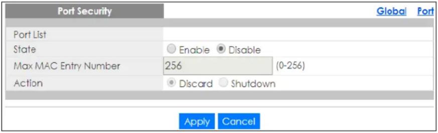
The following table describes the labels in this screen.
Table 150 Configuration > Security > Port Security > Port > Edit
| LABEL DESCRIPTION | |
| Port Security | |
| Port List Displays the port index value. | |
| State | Select Enable or Disable for the Trust status. |
| Max MAC Entry Number | Enter the maximum MAC entry number (maximum MAC entry number can be learned for individual ports). |
| Action | Select the Action as Discard or Shutdown. |
| Apply | Click Apply to save the changes. |
| Cancel | Click Cancel to discard the changes. |
30.3 Port Isolation
30.3.1 Port Isolation Settings
Use this screen to view the Port settings. Click Configuration > Security > Port Isolation to open this screen.
Figure 219 Configuration > Security > Port Isolation
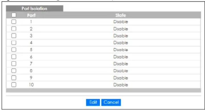
The following table describes the labels in this screen.
Table 151 Configuration > Security > Port Isolation
| LABEL DESCRIPTION | |
| Port Isolation | |
| Port Displays the port index value. | |
| State | Displays the Trust status as Enable or Disable. |
| Edit | Select this check box to configure the properties of a port. Click the Edit button change the properties of the port. |
| Cancel | Click Cancel to discard the changes. |
30.3.2 Port Isolation Edit
Use this screen to configure the Port settings. Click Configuration > Security > Port Isolation > Edit to open this screen.
Figure 220 Configuration > Security > Port Isolation > Edit
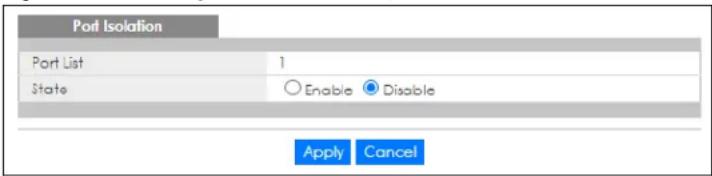
The following table describes the labels in this screen.
Table 152 Configuration > Security > Port Isolation > Edit
| LABEL DESCRIPTION | |
| Port Isolation | |
| Port List Displays the port list index values. | |
| State | Select Enable or Disable for the Protected Port status. |
| Apply | Click Apply to save the changes. |
| Cancel | Click Cancel to discard the changes. |
30.4 802.1X Settings
30.4.1 Global Settings
Use this screen to view the Global settings. Click Configuration > Security > 802.1X > Global to open this screen.
Figure 221 Configuration > Security > 802.1X > Global

The following table describes the labels in this screen.
Table 153 Configuration > Security > 802.1X > Global
| LABEL DESCRIPTION | |
| Global | |
| State Select the 80 | 2.1X security setting to be enabled or disabled. |
| Apply | ClickApplyto save the changes. |
| Cancel | Click Cancelto discard the changes. |
30.4.2 Port Settings
Use this screen to view the Port settings. Click Configuration > Security > 802.1X > Port to open this screen.
Figure 222 Configuration > Security > 802.1X > Port
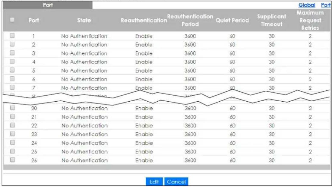
other
| Port | State | Reauthentication | Reauthentication Period | Quiet Period | Supplicant Timeout | Global Port Maximum Request Retries | |---|---|---|---|---|---|---| | 1 | No Authentication | Enable | 3600 | 60 | 30 | 2 | | 2 | No Authentication | Enable | 3600 | 60 | 30 | 2 | | 3 | No Authentication | Enable | 3600 | 60 | 30 | 2 | | 4 | No Authentication | Enable | 3600 | 60 | 30 | 2 | | 5 | No Authentication | Enable | 3600 | 60 | 30 | 2 | | 6 | No Authentication | Enable | 3600 | 60 | 30 | 2 | | 7 | No Authentication | Enable | 3600 | 60 | 30 | 2 | | 8 | ReAuthentication | Enable | 3600 | 60 | 30 | 2 | | 20 | No Authentication | Enable | 3600 | 60 | 30 | 2 | | 21 | No Authentication | Enable | 3600 | 60 | 30 | 2 | | 22 | No Authentication | Enable | 3600 | 60 | 30 | 2 | | 23 | No Authentication | Enable | 3600 | 60 | 30 | 2 | | 24 | No Authentication | Enable | 3600 | 60 | 30 | 2 | | 25 | No Authentication | Enable | 3600 | 60 | 30 | 2 | | 26 | No Authentication | Enable | 3600 | 60 | 30 | 2 | Edit CancelThe following table describes the labels in this screen.
Table 154 Configuration > Security > 802.1X > Port
| LABEL DESCRIPTION | |
| Port | |
| Port Displays the port index value. | |
| State Displays the Trust status as enabled or disabled. | |
| Reauthentication | Displays if Reauthentication function is enabled. If enabled, the subscriber has to periodically re-enter his or her user name and password to stay connected to the port. |
| Reauthentication Period | Displays the Reauthentication period for the function: the period of time when a client has to re-enter his or her user name and password to stay connected to the port. |
| Quiet Period | Display the time out period to transmit request after receiving a rejection from the server. |
| Supplicant Time out | Display the time out period to transmit a request when the client does not respond. |
| Maximum Request Retries | Enter the maximum number of request retries. |
| Edit | Select this check box to configure the properties of a port. Click the Edit button change the properties of the port. |
| Cancel | Click Cancel to discard the changes. |
30.4.3 Port Edit
Use this screen to configure the Port settings. Click Configuration > Security > 802.1X > Port > Edit to open this screen.
Figure 223 Configuration > Security > 802.1X > Port > Edit
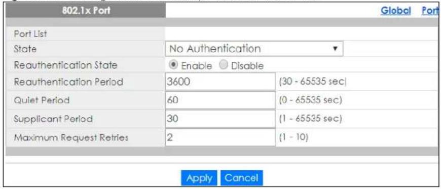
The following table describes the labels in this screen.
Table 155 Configuration > Security > 802.1X > Port > Edit
| LABEL DESCRIPTION | |
| 802.1X Port | |
| Port List Displays the | port index value. |
| State Displays the Trust status as enabled or disabled. | |
| Reauthentication State | Specify if a subscriber has to periodically re-enter his or her user name and password to stay connected to the port. Select Enable to activate feature. |
| Reauthentication Period | Specify how often a client has to re-enter his or her user name and password to stay connected to the port. |
| Quiet Period | Display the time out period to transmit request after receiving a rejection from the sever. |
| Supplicant Period | Display the time out period to transmit a request when the client does not respond. |
| Maximum Request Retries | Enter the maximum number of request retries. |
| Apply | Click Apply to save the changes. |
| Cancel | Click Cancel to discard the changes. |
30.5 DoS Settings
The Switch protects against Denial of Service (DoS) attacks, such as Scan attack and Ping of Death. The goal of DoS attacks is not to steal information, but to disable a device or network on the Internet.
By default, the DoS feature is disabled. You need to enable it on the Switch and its ports. See Table 159 on page 215 for the types of DoS attacks that the Switch prevents when you turn on this feature. You cannot set the Switch to block a specific type of DoS attacks.
Note: DoS protection does not work on LACP-enabled ports.
30.5.1 Global Settings
Use this screen to view the Global settings. Click Configuration > Security > DoS > Global to open this screen.
Figure 224 Configuration > Security > DoS > Global

The following table describes the labels in this screen.
Table 156 Configuration > Security > DoS > Global
| LABEL DESCRIPTION | |
| Global | |
| State Select the DoS security setting to be enabled or disabled. | |
| Apply | ClickApplyto save the changes. |
| Cancel | ClickCancelto discard the changes. |
30.5.2 Port Settings
Use this screen to view the Port settings. Click Configuration > Security > DoS > Port to open this screen.
Figure 225 Configuration > Security > DoS > Port
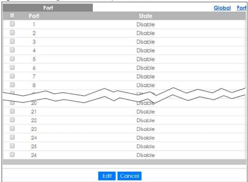
The following table describes the labels in this screen.
Table 157 Configuration > Security > DoS > Port
| LABEL DESCRIPTION | |
| Port | |
| Port Displays the port index value. | |
| State | Displays the port's DoS feature as Enable or Disable. |
| Edit | Select this check box to configure the properties of a port. Click the Edit button change the properties of the port. |
| Cancel | Click Cancel to discard the changes. |
30.5.3 Port Edit
Use this screen to configure the Port settings.
Click Configuration > Security > DoS > Port > Edit to open this screen.
Figure 226 Configuration > Security > DoS > Port > Edit
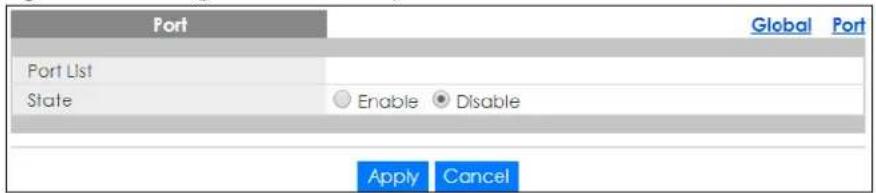
The following table describes the labels in this screen.
Table 158 Configuration > Security > DoS > Port > Edit
| LABEL DESCRIPTION | |
| Port | |
| Port List Displays the | port index value. |
| State | Select Enable to activate the port's DoS feature. |
| Apply | Click Apply to save the changes. |
| Cancel | Click Cancel to discard the changes. |
30.5.4 DoS Attack Types
The following table describes the types of DoS attacks that the Switch can prevent when you enable the DoS feature on the Switch and the ports.
Table 159 DoS Attack Types
| TYPE PACKET TYPE DESCRIPTION | ||
| DA_EQUAL_SA | Layer 2 | These attacks result from sending a specially crafted packet to a machine where the source MAC address is the same as the destination MAC address. The system attempts to reply to itself, resulting in system lockup. |
| LAND | Layer 3 IPv4/IPv6 | These attacks result from sending a specially crafted packet to a machine where the source host IPv4/IPv6 address is the same as the destination host IPv4/IPv6 address. The system attempts to reply to itself, resulting in system lockup. |
| UDP_BLAT/TCP_BLAT (Blat Attack) | Layer 3 IPv4/IPv6 | These attacks result from sending a specially crafted packet to a machine where the source host UDP/TCP port is the same as the destination host UDP/TCP port. The system attempts to reply to itself, resulting in system lockup. |
| PoD (Ping of Death) | Layer 3 IPv4/IPv6 | Ping of Death uses a "ping" utility to create and send an IP packet that exceeds the maximum 65,536 bytes of data allowed by the IP specification. This may cause systems to crash, hang or reboot. |
| IPv6_FRAG_LEN_MIN | Layer 3 IPv6 | This attack uses IPv6 fragmented packets (excluding the last one) whose payload length is less than 1240 bytes. |
| ICMP_FRAG_PKT | Layer 3 IPv4/IPv6 | This attack uses many small fragmented ICMP packets. |
| ICMPv4_PING_MAX / ICMPv6_PING_MAX | Layer 3 IPv4/IPv6 | This attack uses Ping packets whose length is larger than 512 bytes. |
| SMURF | Layer 3 IPv4 | This attack uses Internet Control Message Protocol (ICMP) echo requests packets (pings) to cause network congestion or outages. |
| SYNchronization (SYN), ACKnowledgment (ACK) and FINish (FIN) packets are used to initiate, acknowledge and conclude TCP/IP communication sessions. The following scans exploit weaknesses in the TCP/IP specification and try to illicit a response from a host to identify ports for an attack: | ||
| TCP_HDR_LEN_MIN | Layer 3 IPv4 | TCP packets with header length less than 20 bytes. |
| SYN_SPORT_LESS_1024 | Layer 3 IPv4/IPv6 | TCP SYN packets with source port less than 1024. |
| NULL_SCAN (Scan Attack) | Layer 3 IPv4/IPv6 | TCP sequence number is zero and all control bits are zeros. |
| XMAS (Scan Attack) | Layer 3 IPv4/IPv6 | TCP sequence number is zero and the FIN, URG and PSH bits are set. |
| SYN_FIN | Layer 3 IPv4/IPv6 | SYN and FIN bits are set in the TCP packet. |
CHAPTER 31
Configuration: AAA
31.1 Overview
This section provides information for AAA in Configuration.
Use the AAA screens to configure authentication, authorization and accounting settings on the Switch.
31.2 Auth Method
Authentication is the process of determining who a user is and validating access to the Switch. The Switch can authenticate users who try to log in based on user accounts configured on the Switch itself. The Switch can also use an external authentication server to authenticate a large number of users.
31.2.1 Auth Method Settings
Use this screen to view the Auth Method settings. Click Configuration > AAA > Auth Method to open this screen.
Figure 227 Configuration > AAA > Auth Method
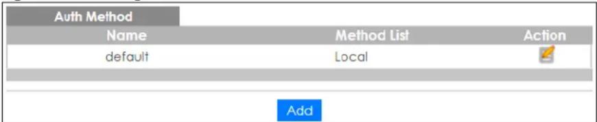
The following table describes the labels in this screen.
Table 160 Configuration > AAA > Auth Method
| LABEL DESCRIPTION | |
| Auth Method | |
| Name | Displays the authentication method name. The name can be between 1 and 31 ASCII Alphanumeric Characters. |
| Method List | Displays the list of authentication methods as being Local or Radius or TACACS+. |
| Action | Click the Action button to change the configuration settings for a VLAN entry. |
| Add | Click Add to create a new Auth Method entry. |
31.2.2 Auth Method Add or Edit
Use this screen to configure the Auth Method settings. Click Configuration > AAA > Auth Method > Add or Edit to open this screen.
Figure 228 Configuration > AAA > Auth Method > Add or Edit
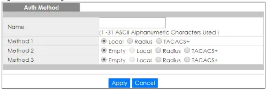
The following table describes the labels in this screen.
Table 161 Configuration > AAA > Auth Method > Add or Edit
| LABEL DESCRIPTION | |
| Auth Method | |
| Name Enter the authentication method name. The name can be between 1 and 31 ASCII Alphanumeric Characters. | |
| Method 1 | Select the first authentication method as being Local, Radius, or TACACS+. |
| Method 2 | Select the second authentication method as being Empty, Local, Radius, or TACACS+. |
| Method 3 | Select the third authentication method as being Empty, Local, Radius, or TACACS+. |
| Apply | Click Apply to save the changes. |
| Cancel | Click Cancel to discard the changes. |
31.3 RADIUS Settings
31.3.1 RADIUS
Use this screen to configure the RADIUS settings. Click Configuration > AAA > RADIUS to open this screen.
Figure 229 Configuration > AAA > RADIUS

The following table describes the labels in this screen.
Table 162 Configuration > AAA > RADIUS
| LABEL DESCRIPTION | |
| RADIUS Servers | |
| Server Displays the | server names as an IP address or a domain name. |
| Auth Port | Displays the authentication port numbers as a value between 0 and 65535. |
| Key Displays the authentication key. | |
| Time out | Displays the number of time outs for replies. The value can be between 1 and 30 seconds. |
| Retries | Displays the number of retries. The value can be between 1 and 30. |
| Priority | Displays the server priority asHighor Low. |
| Usage Type | Displays the server usage type asLogin, 802.1X, orAll. |
| Action | |
| Edit | Click toEditmodify the entry. |
| Delete | ClickDeleteto delete the entry. |
| Add | ClickAddto create a newServerentry. |
31.3.2 RADIUS Add or Edit
Use this screen to configure the RADIUS settings. Click Configuration > AAA > RADIUS > Add or Edit to open this screen.
Figure 230 Configuration > AAA > RADIUS > Add or Edit
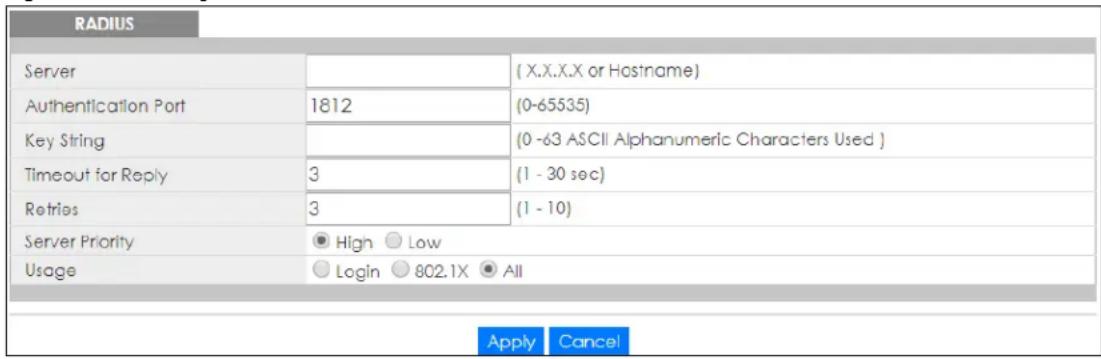
The following table describes the labels in this screen.
Table 163 Configuration > AAA > RADIUS > Add or Edit
| LABEL DESCRIPTION | |
| RADIUS | |
| Server Enter the server names as an IP address or a domain name. | |
| Authentication Port | Enter the authentication port numbers as a value between 0 and 65535. |
| Key String Enter the authentication key string: 0 – 63 ASCII Alphanumeric Characters. | |
| Timeout for Reply | Enter the number of time outs for replies. The value can be between 1 and 30 seconds. |
| Retries | Enter the number of retries. The value can be between 1 and 30. |
| Server Priority | Select the server priority as High or Low. |
| Usage | Select the server usage type as Login, 802.1X, or All. |
| Apply | Click Apply to save the changes. |
| Cancel | Click Cancel to discard the changes. |
31.4 TACACS+ Settings
31.4.1 TACACS+
Use this screen to configure the TACACS+ settings. Click Configuration > AAA > TACACS+ to open this screen.
Figure 231 Configuration > AAA > TACACS+

The following table describes the labels in this screen.
Table 164 Configuration > AAA > TACACS+
| LABEL DESCRIPTION | |
| TACACS+ Servers | |
| Server Displays the | server names as an IP address or a domain name. |
| Port | Displays the port numbers as a value between 0 and 65535. |
| Key Displays the authentication key. | |
| Timeout | Displays the number of time outs for replies. The value can be between 1 and 30 seconds. |
| Priority | Displays the priority as High or Low. |
| Action | |
| Edit | Click to Edit modify the entry. |
| Delete | Click Delete to delete the entry. |
| Add | Click Add to create a new Server entry. |
31.4.2 TACACS+ Add or Edit
Use this screen to configure the TACACS+ settings. Click Configuration > AAA > TACACS+ > Add or Edit to open this screen.
Figure 232 Configuration > AAA > TACACS+ > Add or Edit
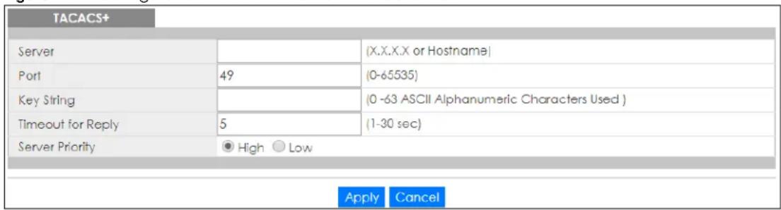
The following table describes the labels in this screen.
Table 165 Configuration > AAA > TACACS+ > Add or Edit
| LABEL DESCRIPTION | |
| TACACS+ | |
| Server Enter the server names as an IP address or a domain name. | |
| Port | Enter the port numbers as a value between 0 and 65535. |
| Key String Enter the authentication key string: 0 – 63 ASCII alphanumeric characters. | |
| Timeout for Reply | Enter the number of time outs for replies. The value can be between 1 and 30 seconds. |
| Server Priority | Select the server priority as High or Low. |
| Apply | Click Apply to save the changes. |
| Cancel | Click Cancel to discard the changes. |
CHAPTER 32
Configuration: Management
32.1 Overview
This section provides information for Management in Configuration.
Use the Management screens to configure settings on the Switch. The following sub-menus are accessed from this section: Syslog, SNMP, Error Disable, HTTP/HTTPS, TELNET/SSH, Users, Remote Access Control.
32.2 Syslog Settings
The syslog feature can stores logs in the Switch's memory or sends logs to an external syslog server.
32.2.1 Global Settings
Use this screen to view and configure the Global settings. Click Configuration > Management > Syslog > Global to open this screen.
Figure 233 Configuration > Management > Syslog > Global

The following table describes the labels in this screen.
Table 166 Configuration > Management > Syslog > Global
| LABEL DESCRIPTION | |
| Global | |
| State | Select Enable to turn on syslog (system logging) on the Switch. Otherwise, select Disable to turn it off. |
| Apply | Click Apply to save the changes. |
| Cancel | Click Cancel to discard the changes. |
32.2.2 Local Settings
Use this screen to view the Local settings. Click Configuration > Management > Syslog > Local to open this screen.
Figure 234 Configuration > Management > Syslog > Local
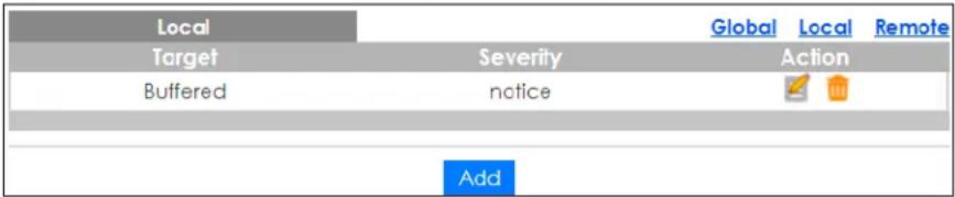
The following table describes the labels in this screen.
Table 167 Configuration > Management > Syslog > Local
| LABEL DESCRIPTION | |
| Local | |
| Target Displays the | local storage target for logging messages.It shows whether the logs are stored in the Switch's run-time memory buffer or flash (permanent) memory. If the logs are stored in the Switch's memory buffer, the logs will be erased when the Switch reboots. |
| Severity | Displays the severity level of messages to be stored in the Switch's memory.The Switch stores the messages of that severity level or higher. |
| Action | |
| Edit | Click Edit to make changes to the entry. |
| Delete | Click Delete to remove the entry. |
| Add | Click Add to create a new Local entry. |
32.2.3 Local Add or Edit
Use this screen to configure the Local settings. Click Configuration > Management > Syslog > Local > Add or Edit to open this screen.
Figure 235 Configuration > Management > Syslog > Local > Add or Edit
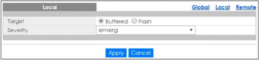
The following table describes the labels in this screen.
Table 168 Configuration > Management > Syslog > Local > Add or Edit
| LABEL DESCRIPTION | |
| Local | |
| Target | Select the local storage target for logging messages. The options areBufferedorFlash. |
| Severity | Select the severity level of the messages that you want to save in the Switch’s memory. The Switch stores the logging messages with the severity level equal to or higher than what you selected. For example, if you selectwarning, all messages with thewarning,error,crit,alertoremergseverity level will be stored. |
| Apply | ClickApplyto save the changes. |
| Cancel | ClickCancelto discard the changes. |
32.2.4 Remote Settings
Use this screen to view the Remote settings. Click Configuration > Management > Syslog > Remote to open this screen.
Figure 236 Configuration > Management > Syslog > Remote

The following table describes the labels in this screen.
Table 169 Configuration > Management > Syslog > Remote
| LABEL DESCRIPTION | |
| Remote | |
| Server | Displays the external syslog server information which includes the server IP address and port number. |
| Severity Displays the severity level of messages to be sent to the syslog server.The Switch sends the messages of that severity level or higher. | |
| Facility | Displays the facility designation of the remote entry. |
| Action | |
| Edit | Click Edit to make changes to the entry. |
| Delete | Click Delete to remove the entry. |
| Add | Click Add to create a new Remote entry. |
32.2.5 Remote Add or Edit
Use this screen to add an external syslog server. Click Configuration > Management > Syslog > Remote > Add or Edit to open this screen.
Figure 237 Configuration > Management > Syslog > Remote > Add or Edit
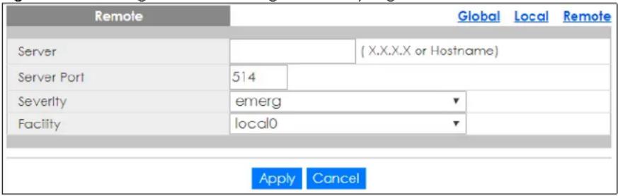
The following table describes the labels in this screen.
Table 170 Configuration > Management > Syslog > Remote > Add or Edit
| LABEL DESCRIPTION | |
| Remote | |
| Server Enter the IP | address or domain name of the syslog server. |
| Server Port Enter port number of the syslog server. | |
Table 170 Configuration > Management > Syslog > Remote > Add or Edit
| LABEL DESCRIPTION | |
| Severity | Select the severity level of the messages that you want the Switch to send to this syslog server. The Switch sends the logging messages with the severity level equal to or higher than what you selected. For example, if you select warning, all messages with the warning, error, crit, alert or emerg severity level will be sent. |
| Facility | Select the log facility from the dropdown list. The log facility allows you to send logs to different files in the syslog server. Refer to the documentation of your syslog program for more details. |
| Apply | Click Apply to save the changes. |
| Cancel | Click Cancel to discard the changes. |
32.3 SNMP Settings
Simple Network Management Protocol (SNMP) is an application layer protocol used to manage and monitor TCP/IP-based devices. SNMP is used to exchange management information between the network management system (NMS) and a network element (NE). A manager station can manage and monitor the Switch through the network through SNMP version 1 (SNMPv1), SNMP version 2c or SNMP version 3.
32.3.1 Global Settings
Use this screen to view and configure the Global settings. Click Configuration > Management > SNMP > Global to open this screen.
Figure 238 Configuration > Management > SNMP > Global

The following table describes the labels in this screen.
Table 171 Configuration > Management > SNMP > Global
| LABEL DESCRIPTION | |
| Global | |
| State Select the global SNMP setting to be enabled or disabled. | |
| Apply | Click Apply to save the changes. |
| Cancel | Click Cancel to discard the changes. |
32.3.2 Community Settings
Use this screen to view the Community settings. Click Configuration > Management > SNMP > Community to open this screen.
Figure 239 Configuration > Management > SNMP > Community
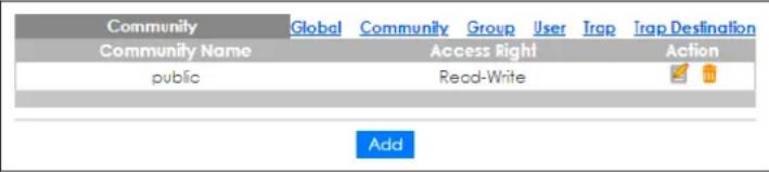
The following table describes the labels in this screen.
Table 172 Configuration > Management > SNMP > Community
| LABEL DESCRIPTION | |
| Community | |
| Community Name | Displays a string identifying the community name that this entry should belong to. The allowed string length is 1 to 20, and the allowed content is ASCII characters from 33 to 126. |
| Access Right | Displays the access mode for this entry. The possible values are Read-Only and Read-Write. |
| Action | |
| Edit | Click Edit to make changes to the entry. |
| Delete | Click Delete to remove the entry. |
| Add | Click Add to create a new SNMP Community entry. |
32.3.3 Community Add or Edit
Use this screen to configure the Community settings. Click Configuration > Management > SNMP > Community > Add or Edit to open this screen.
Figure 240 Configuration > Management > SNMP > Community > Add or Edit
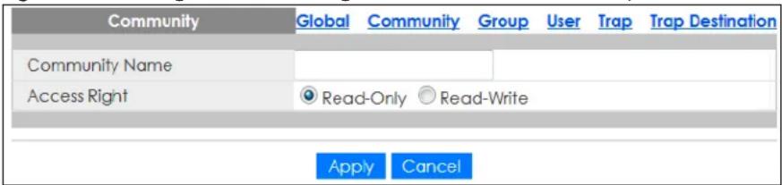
The following table describes the labels in this screen.
Table 173 Configuration > Management > SNMP > Community > Add or Edit
| LABEL DESCRIPTION | |
| Community | |
| Community Name | Enter a string identifying the community name that this entry should belong to. The allowed string length is 1 to 20, and the allowed content is ASCII characters from 33 to 126. |
| Access Right | Select the access mode for this entry. The possible values are Read-Only and Read-Write. |
| Apply | Click Apply to save the changes. |
| Cancel | Click Cancel to discard the changes. |
32.3.4 Group Settings
Use this screen to view the Group settings. Click Configuration > Management > SNMP > Group to open this screen.
Figure 241 Configuration > Management > SNMP > Group
| SNMPv3 Group | Global Community Group User Trap Trap Destination | |||
| Group Name | Security Model | Security Level | Access Right | Action |
| TW | v3 | noauth | Read-Only | |
| TW-1 | v3 | auth | Read-Only | |
| TW-2 | v3 | noauth | Read-Write | |
| TW-3 | v3 | priv | Read-Only | |
| TW-4 | v3 | auth | Read-Write | |
| TW-5 | v3 | priv | Read-Write | |
The following table describes the labels in this screen.
Table 174 Configuration > Management > SNMP > Group
| LABEL DESCRIPTION | |
| SNMPv3 Group | |
| Group Name | Displays a string identifying the group name that this entry should belong to. The allowed string length is 1 to 30, and the allowed content is ASCII characters from 33 to 126. |
| Security Model Displays the security model that this entry belongs to.v3: Reserved for SNMPv3. | |
| Security Level | Displays the security level that this entry belongs to. Possible security levels are:noauth: No authentication and no privacy.auth: Authentication and no privacy.Priv: Authentication and privacy. |
| Access Right | Displays the access mode for this entry. The possible values are Read Only and Read-Write. |
| Action | |
| Edit | Click Edit to make changes to the entry. |
| Delete | Click Delete to remove the entry. |
| Add | Click Add to create a new SNMPv3 Group entry. |
32.3.5 Group Add or Edit
Use this screen to configure the Group settings. Click Configuration > Management > SNMP > Group > Add or Edit to open this screen.
Figure 242 Configuration > Management > SNMP > Group > Add or Edit
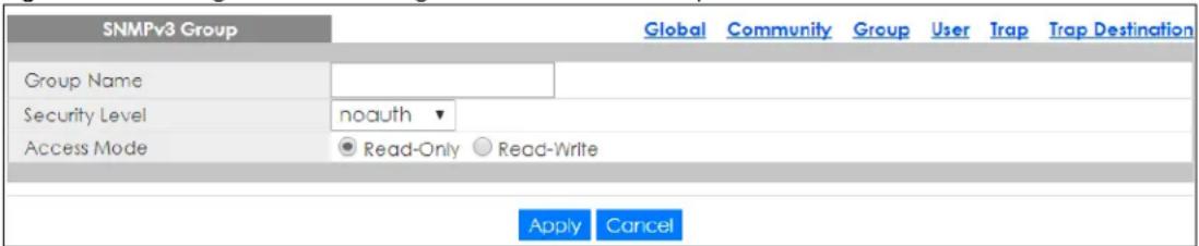
The following table describes the labels in this screen.
Table 175 Configuration > Management > SNMP > Group > Add or Edit
| LABEL DESCRIPTION | |
| SNMPv3 Group | |
| Group Name | Enter a string identifying the group name that this entry should belong to. The allowed string length is 1 to 30, and the allowed content is ASCII characters from 33 to 126. |
| Security Level | Select the security level that this entry belongs to. Possible security levels are:noauth: No authentication and no privacy.auth: Authentication and no privacy.priv: Authentication and privacy. |
| Access Mode | Select the access mode for this entry. The possible values are Read-Only and Read-Write. |
| Apply | Click Apply to save the changes. |
| Cancel | Click Cancel to discard the changes. |
32.3.6 User Settings
Use this screen to view the User settings. Click Configuration > Management > SNMP > User to open this screen.
Figure 243 Configuration > Management > SNMP > User

The following table describes the labels in this screen.
Table 176 Configuration > Management > SNMP > User
| LABEL DESCRIPTION | |
| SNMP User | |
| User Name | Displays a string identifying the user name that this entry belongs to. The allowed string length is 1 to 30, and the allowed content is ASCII characters from 33 to 126. |
| Group | Displays a string identifying the group name that this entry belongs to. The allowed string length is 1 to 30, and the allowed content is ASCII characters from 33 to 126. |
| Privilege Mode | Displays the privilege mode that this entry belongs to. |
| Authentication Protocol | Displays the authentication protocol that this entry belongs to. Possible authentication protocols are:None: No authentication protocol.MD5: An optional flag to indicate that this user uses MD5 authentication protocol.SHA: An optional flag to indicate that this user uses SHA authentication protocol.The value of the security level cannot be modified if the entry already exists. That means you must first ensure that the value is set correctly. |
| Encryption Protocol | Displays the encryption protocol that this entry belongs to. |
| Access Right | Displays the access mode for this entry. The possible values are Read-Only and Read-Write. |
| Action | |
| Edit | Click Edit to make changes to the entry. |
| Delete | Click Delete to remove the entry. |
| Add Click Add to create a new SNMP user. | |
32.3.7 User Add or Edit
Use this screen to configure the User settings. Click Configuration > Management > SNMP > User > Add or Edit to open this screen.
Figure 244 Configuration > Management > SNMP > User > Add or Edit
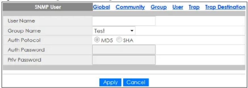
The following table describes the labels in this screen.
Table 177 Configuration > Management > SNMP > User > Add or Edit
| LABEL DESCRIPTION | |
| SNMP User | |
| User Name | Enter a string identifying the user name that this entry belongs to. The allowed string length is 1 to 30, and the allowed content is ASCII characters from 33 to 126. |
| Group Name | Enter a string identifying the group name that this entry belongs to. The allowed string length is 1 to 30, and the allowed content is ASCII characters from 33 to 126. |
| Auth Protocol | Select the authentication protocol that this entry belongs to. Possible authentication protocols are:MD5: An optional flag to indicate that this user uses MD5 authentication protocol.SHA: An optional flag to indicate that this user uses SHA authentication protocol.The value of the security level cannot be modified if the entry already exists. That means you must first ensure that the value is set correctly. |
| Auth Password | Enter a string identifying the authentication password phrase. For MD5 authentication protocol, the allowed string length is 8 to 32. For SHA authentication protocol, the allowed string length is 8 to 32. The allowed content is ASCII characters from 33 to 126. |
| Priv Password | Enter a string identifying the privacy password phrase. The allowed string length is 8 to 64 and the allowed content is ASCII characters from 33 to 126. |
| Apply | Click Apply to save the changes. |
| Cancel | Click Cancel to discard the changes. |
32.3.8 Trap Settings
Use this screen to configure the Trap settings. Click Configuration > Management > SNMP > Trap to open this screen.
Figure 245 Configuration > Management > SNMP > Trap
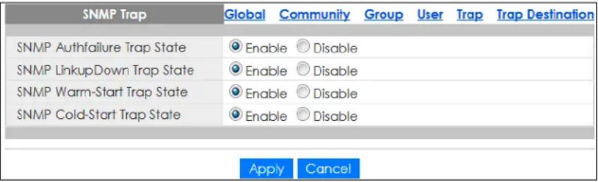
The following table describes the labels in this screen.
Table 178 Configuration > Management > SNMP > Trap
| LABEL DESCRIPTION | |
| SNMP Trap | |
| SNMP Authfailure Trap State | Select the SNMP entity is permitted to generate authentication failure traps. Possible modes are:Enabled: Enable SNMP trap authentication failure.Disabled: Disable SNMP trap authentication failure. |
| SNMP LinkupDown Trap State | Select the SNMP trap link-up and link-down mode operation. Possible modes are:Enabled: Enable SNMP trap link-up and link-down mode operation.Disabled: Disable SNMP trap link-up and link-down mode operation. |
| SNMP Warm-Start Trap State | Reboot using software or hardware button reboot. |
| SNMP Cold-Start Trap State | Reboot though power off. |
| Apply | ClickApplyto save the changes. |
| Cancel | ClickCancelto discard the changes. |
32.3.9 Trap Destination
Use this screen to view the Trap Destination settings. Click Configuration > Management > SNMP > Trap Destination to open this screen.
Figure 246 Configuration > Management > SNMP > Trap Destination

The following table describes the labels in this screen.
Table 179 Configuration > Management > SNMP > Trap Destination
| LABEL DESCRIPTION | |
| SNMP Trap Host | |
| Server Displays a string identifying the server address that this entry belongs to. | |
| Version Indicates the SNMP trap supported version. Possible versions are:• v1: Set SNMP trap supported version 1.• v2c: Set SNMP trap supported version 2c.• v3: Set SNMP trap supported version 3. | |
| Community/User Name | Displays the community or user name that this entry belongs to. |
| UDP Port Displays the trap use destination for the UDP port. | |
| Action | |
| Edit | Click Edit to make changes to the entry. |
| Delete | Click Delete to remove the entry. |
| Add | Click Add to create a new SNMP Trap Host entry. |
32.3.10 Trap Destination Add or Edit
Use this screen to configure the Trap Destination settings. Click Configuration > Management > SNMP > Trap Destination > Add or Edit to open this screen.
Figure 247 Configuration > Management > SNMP > Trap Destination > Add or Edit
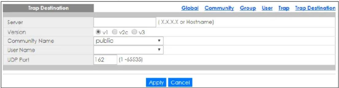
The following table describes the labels in this screen.
Table 180 Configuration > Management > SNMP > Trap Destination > Add or Edit
| LABEL DESCRIPTION | |
| Trap Destination | |
| Server Enter the IP | address of the server or a string identifying the server address that this entry belongs to. |
| Version Select the | SNMP trap supported version. Possible versions are:• v1: Set SNMP trap supported version 1.• v2c: Set SNMP trap supported version 2c.• v3: Set SNMP trap supported version 3. |
| Community Name | Displays the community name that this entry belongs to. |
| User Name Displays the user name that this entry belongs to. | |
| UDP Port Enter a UDP port for this entry. | |
| Apply | Click Apply to save the changes. |
| Cancel | Click Cancel to discard the changes. |
32.4 Error Disable
32.4.1 Error Disable Settings
Use this screen to configure the Error Disabled settings. Click Configuration > Management > Error Disable to open this screen.
Figure 248 Configuration > Management > Error Disable
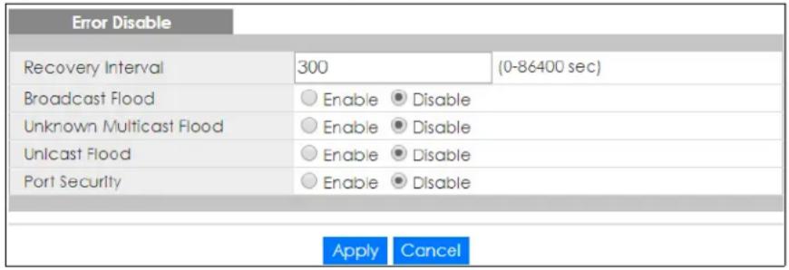
The following table describes the labels in this screen.
Table 181 Configuration > Management > Error Disable
| LABEL DESCRIPTION | |
| Error Disable | |
| Recovery Interval | Enter the recovery interval value. |
| Broadcast Flood | Select an option to Enable or Disable the Broadcast Flood. |
| Unknown Multicast Flood | Select an option to Enable or Disable the Unknown Multicast Flood. |
| Unicast Flood | Select an option to Enable or Disable the Unicast Flood. |
| Port Security | Select an option to Enable or Disable the Port Security. |
| Apply | Click Apply to save the changes. |
| Cancel | Click Cancel to discard the changes. |
32.5 HTTP/HTTPS
32.5.1 HTTP Settings
Use this screen to configure the HTTP settings. Click Configuration > Management > HTTP/HTTPS > HTTP to open this screen.
Figure 249 Configuration > Management > HTTP/HTTPS > HTTP
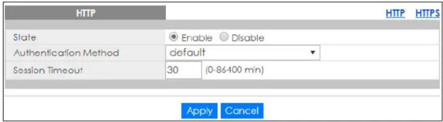
The following table describes the labels in this screen.
Table 182 Configuration > Management > HTTP/HTTPS > HTTP
| LABEL DESCRIPTION | |
| HTTP | |
| State Select the HTTP mode operation. Possible modes are: • Enabled: Enable HTTP mode operation. • Disabled: Disable HTTP mode operation. | |
| Authentication Method | Select the authentication method from the dropdown list. |
| Session Timeout Enter the session timeout value. The timeout can be between 0 and 86400 minutes. | |
| Apply | Click Apply to save the changes. |
| Cancel | Click Cancel to discard the changes. |
32.5.2 HTTPS Settings
Use this screen to configure the HTTPS settings. Click Configuration > Management > HTTP/HTTPS > HTTPS to open this screen.
Figure 250 Configuration > Management > HTTP/HTTPS > HTTPS
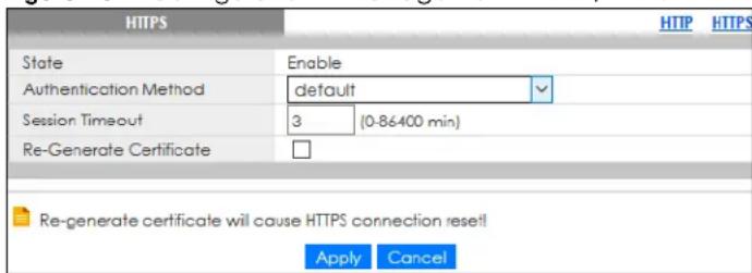
The following table describes the labels in this screen.
Table 183 Configuration > Management > HTTP/HTTPS > HTTPS
| LABEL DESCRIPTION | |
| HTTPS | |
| State Select the HTTPS mode operation.Possible mode is:Enable: Enable HTTPS mode operation. | |
| Authentication Method | Select the authentication method from the dropdown list. |
| Session Timeout Enter the session timeout value. The timeout can be between 0 and 86400 minutes. | |
| Re-Generate Certificate | Click this to renew the HTTPS certificate that is verified by a third-party to create secure HTTPS connections between your computer and the Switch. This allows you to securely access the Switch using the Web Configurator.Note: Re-generating the certificate will cause a network connection reset. |
| Apply | Click Apply to save the changes. |
| Cancel | Click Cancel to discard the changes. |
32.6 TELNET/SSH
32.6.1 TELNET Settings
Use this screen to configure the TELNET settings. Click Configuration > Management > TELNET/SSH > TELNET to open this screen.
Figure 251 Configuration > Management > TELNET/SSH > TELNET
| TELNET | TELNET | SSH | ||
| State | ○ Enable | ● Disable | ||
| Apply | Cancel | |||
The following table describes the labels in this screen.
Table 184 Configuration > Management > TELNET/SSH > TELNET
| LABEL DESCRIPTION | |
| TELNET | |
| State | You can allow the Switch for remote Telnet access. The administrator uses Telnet from a computer on a remote network to access the Switch.Enable: allow remote Telnet access.Disable: do not allow remote Telnet access. |
| Apply | ClickApplyto save the changes. |
| Cancel | ClickCancelto discard the changes. |
32.6.2 SSH Settings
Use this screen to configure the SSH settings. Click Configuration > Management > TELNET/SSH > SSH to open this screen.
Figure 252 Configuration > Management > TELNET/SSH > SSH
| SSH | TELNET | SSH | |||
| State | ○ Enable | ● Disable | |||
| Apply | Cancel | ||||
The following table describes the labels in this screen.
Table 185 Configuration > Management > TELNET/SSH > SSH
| LABEL DESCRIPTION | |
| SSH | |
| State | You can allow a remote computer to access the Switch using SSH (Secure SHell protocol).Enable: allow SSH connection.Disable: do not allow SSH connection. |
| Apply | ClickApplyto save the changes. |
| Cancel | Click Cancelto discard the changes. |
32.7 Users Settings
32.7.1 Users
Use this screen to configure the Users settings. Click Configuration > Management > Users to open this screen.
Figure 253 Configuration > Management > Users
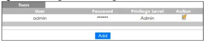
The following table describes the labels in this screen.
Table 186 Configuration > Management > Users
| LABEL DESCRIPTION | |
| Users | |
| User | A string identifying the user name that this entry should belong to. The allowed string length is 1 to 32. The valid user name is a combination of letters, numbers and underscores. |
| Password Displays | the password of the user. The allowed string length is 1 to 64. |
| Privilege Level Displays | the privilege level of the user, range: admin and user. |
| Action | |
| Edit | Click Edit to make changes to the entry. |
| Delete | Click Delete to remove the entry. |
| Add | Click Add to create a new User entry. |
32.7.2 Users Add or Edit
Use this screen to configure the Users settings. Click Configuration > Management > Users > Add or Edit to open this screen.
Figure 254 Configuration > Management > Users > Add or Edit
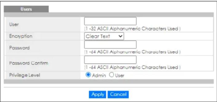
The following table describes the labels in this screen.
Table 187 Configuration > Management > Users > Add or Edit
| LABEL DESCRIPTION | |
| Users | |
| User | Enter a string identifying the user name that this entry should belong to. The allowed string length is 1 to 32. The valid user name is a combination of letters, numbers and underscores. |
| Encryption | Select how the password is shown in theConfiguration > Management > Usersscreen and in the configuration file saved inMaintenance > Configuration > Backup.Note: Make sure to selectEncryptedto avoid displaying passwords as plain text in theUsersscreen and configuration file.Clear Text– The password is shown in plain text.Encrypted– The password is shown as asterisks (*).Note: Be careful who can access configuration files with no password or clear text passwords. |
| Password | Enter a password using the keyboard characters ("a – z", "A – Z", "0 – 9", ~!@#$%^&*()_+`-=[]::<>./) for the user. The allowed string length is 1 to 64. |
| Password Confirm | Enter the same password again to confirm. |
| Privilege Level | Select the privilege level of the user range:AdminandUser. |
| Apply | ClickApplyto save the changes. |
| Cancel | ClickCancelto discard the changes. |
32.8 Remote Access Control
32.8.1 Global Settings
Use this screen to configure the Global settings. Click Configuration > Management > Remote Access Control > Global to open this screen.
Figure 255 Configuration > Management > Remote Access Control > Global
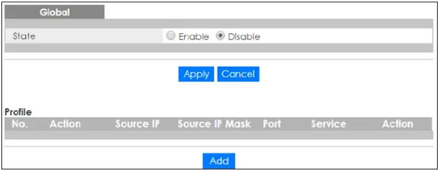
The following table describes the labels in this screen.
Table 188 Configuration > Management > Remote Access Control > Global
| LABEL DESCRIPTION | |
| Global | |
| State Select the global remote access setting to be enabled or disabled. | |
| Apply | Click Apply to save the changes. |
| Cancel | Click Cancel to discard the changes. |
| Profile | |
| No. | Displays the priority level of the entry. The value can be between 1 and 16. |
| Action | Displays the action value. The values are Permit or Deny. |
| Source IP Display the source IP value. | |
| Source IP Mask Displays the source IP mask. | |
| Port Display the port value. | |
| Service | Display the service used for remote access. The values are ALL, HTTP, HTTPS, or SNMP. |
| Action | |
| Edit | Click Edit to make changes to the entry. |
| Delete | Click Delete to remove the entry. |
| Add Click Add to create a new profile entry. | |
32.8.2 Profile Add or Edit
Use this screen to configure the Profile settings. Click Configuration > Management > Remote Access Control > Global > Add or Edit to open this screen.
Figure 256 Configuration > Management > Remote Access Control > Global > Add or Edit
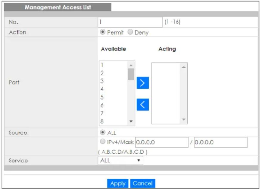
The following table describes the labels in this screen.
Table 189 Configuration > Management > Remote Access Control > Global > Add or Edit
| LABEL DESCRIPTION | |
| Management Access List | |
| No. | Enter the priority level of the entry. The value can be between 1 and 16. |
| Action | Select the action value. The values are Permit or Deny. |
| Port | Select a value in Available and click the Add (>) icon to transfer to the Acting column.Select a value in Acting and click the Remove (<) icon to transfer to the Available column. |
| Source | Select the source IP value. The options are ALL or IPv4/ Mask. |
| IPv4/Mask Select and enter the IPv4 address and subnet mask of a computer which will be allowed or denied to access the Switch. | |
| Service | Select the service to use for remote access. The values are ALL, HTTP, HTTPS, or SNMP. |
| Apply | Click Apply to save the changes. |
| Cancel | Click Cancel to discard the changes. |
CHAPTER 33
Maintenance
33.1 Firmware Upgrade
33.1.1 Overview
Firmware updates contain bug fixes and fixes for security vulnerabilities. It is recommended to keep the Switch's firmware up to date. You can upgrade the Switch's firmware manually using a file downloaded on your computer or through the online Web Configurator.
Note: Be sure to upload the correct model firmware as uploading the wrong model firmware may damage your device.
From the Maintenance screen, display the Upload screen as shown next. Use this screen to upgrade the Switch's firmware.
Figure 257 Maintenance > Firmware > Upload
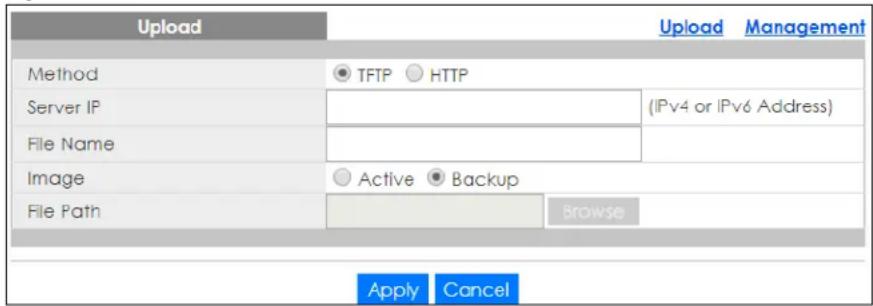
The following table describes the labels under Upload.
Table 190 Maintenance > Firmware > Upload
| LABEL DESCRIPTION | |
| Upload | |
| Method | Choose HTTP to use the Web Configurator for the firmware upload. Alternatively, choose TFTP to download the firmware from a TFTP server. |
| Server IP | To download from a TFTP server, enter the TFTP server IP address. |
| File Name | Enter the name of the firmware file on the TFTP server. |
| Image | Choose Backup to upload the firmware file as the backup image. Alternatively, choose Active to upload the firmware file as the active image. |
| File Path | Browse to the path on your computer to upload the firmware you want as the active image. |
33.1.2 Upgrade the firmware from a file on a server
Follow the steps below to upgrade the firmware from a TFTP server.
- In Method, choose TFTP.
- In Server IP, enter the TFTP server IP address.
- In File Name, enter the name of the firmware file on the TFTP server.
- In Image, choose Backup to upload the firmware file as the backup image. OR
Choose Active to upload the firmware file as the active image.
- Click Apply to upgrade the chosen image.
OR
Click Cancel to discard the changes.
After the firmware upgrade process is complete, see the System Info screen to verify your current firmware version number.
33.1.3 Upgrade the firmware from a file on your computer
Note: For manual upgrade, make sure you have downloaded (and unzipped) the correct model firmware and version to your computer before uploading it to the device. The file name should have a .bix extension.
Follow the steps below to upgrade the firmware from a file on your computer.
- In Method, choose HTTP.
- In Image, choose Active to upload the firmware file on the active partition image. OR
Choose Backup to upload the firmware file on the backup partition image.
- In File Path, click Browse to display the Choose File screen from which you can locate the firmware file in the bix format on your computer.
- Click Apply to upload the chosen file.
OR
Click Cancel to discard the changes.
After the firmware upgrade process is complete, see the System Info screen to verify your current firmware version number.
33.2 Firmware Management
33.2.1 Overview
The Firmware Management screen provides instant access to the firmware versions installed on your Switch. Active and backup firmware versions are saved as images on flash partitions. The backup image is used when the active partition has problems during boot.
From the Maintenance screen, display the Firmware Management screen as shown next. Use this screen to view image information and activate an image.
Figure 258 Maintenance > Firmware > Management
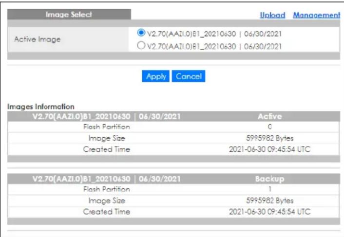
The following table describes the labels shown under Images Information.
Table 191 Maintenance > Firmware > Management
| LABEL DESCRIPTION | |
| Image Select | |
| Active Image | Select which firmware should load, clickApplyand reboot the Switch to see changes. |
| Apply | ClickApplyto save the changes. |
| Cancel | ClickCancelto discard the changes. |
| Images Information | |
| Flash Partition Displays the partition number. | |
| Image Size Displays the size of the partition image in bytes. | |
| Created Time | Displays the date and time when the image was created in the Coordinated Universal Time (UTC) format. |
33.2.2 Select the Active Image
The available partition is shown under Image Select.
Follow the steps below to choose the active image, which will be the default partition during boot. When you selected the active image and saved the changes, the other one will be the backup.
If you are facing problems with the active partition when booting, the Switch will use the backup one and it'll be loaded automatically.
- In Active Image, choose the backup image according to the information displayed in Images Information.
- Click Apply to activate the backup image.
OR
Click Cancel to discard the changes.
33.3 Backup a Configuration File
33.3.1 Overview
You can save various "snapshots" of your device to the server or your computer and restore them at a later date, if required.
Click Maintenance > Configuration > Backup to display the screen as shown next. Use this screen to back up your current Switch configuration and log files to a server or as local files to your computer.
Figure 259 Maintenance > Configuration > Backup
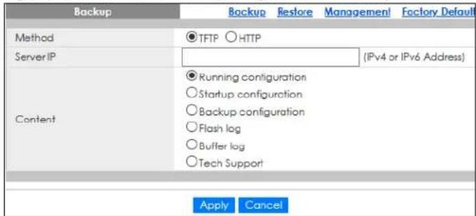
The following table describes the labels under Backup.
Table 192 Maintenance > Configuration > Backup
| LABEL DESCRIPTION | |
| Backup | |
| Method | Choose HTTP to use the Web Configurator to backup the configuration. Alternatively, choose TFTP to upload the snapshot to a TFTP server. |
| Server IP To upload | the backup to a TFTP server, enter the TFTP server IP address. |
| Content | Choose the type of file for backup. You can back up configuration files (running, startup, or backup) or log files (flash or buffer).There are three different types of configuration files:Backup configuration – this is saved in the Switch. If you make changes to the current configuration, and there are problems, you can revert to the Backup configuration without having to restore a new fileStartup configuration – this is the configuration used when the Switch is booting up.Running configuration – this is the configuration when the Switch is running.There are two different types of log files:Flash log: Select this to save logs in the Switch's flash (permanent) memory.Buffer log: Select this to save logs in the Switch's memory buffer. If the logs are stored in the Switch's memory buffer, the logs will be erased when the Switch reboots.Tech Support: Select this to upload the configuration/log files to the TFTP server. The log files contain useful information such as CPU utilization, history, memory and Mbuf (Memory Buffer) log, and crash reports for issue analysis by customer support should you have difficulty with your Switch. |
| Apply | Click Apply to save the changes. |
| Cancel | Click Cancel to discard the changes. |
33.3.2 Back up configuration or log files to a server
Follow the steps below to backup configuration or log files to a TFTP server.
- In Method, choose TFTP.
- In Server IP, enter the TFTP server IP address.
- In Content, choose any one file type.
- Click Apply to save a snapshot of your current configuration to the TFTP server. OR
Click Cancel to discard the changes.
33.3.3 Back up configuration or log files to your computer
Follow the steps below to backup configuration or log files to your computer.
- In Method, choose HTTP.
- In Content, choose any one file type.
- Click Apply to display the Save File screen from which you can save the configuration file in the cfg format or the log file in the log format to your computer.
OR
Click Cancel to discard the changes.
33.4 Restore a Configuration File
33.4.1 Overview
You can restore a previously saved device configuration from the server or your computer.
Click Maintenance > Configuration > Restore to display the screen as shown next. Use this screen to restore a previously saved configuration from a server or your computer.
Figure 260 Maintenance > Configuration > Restore
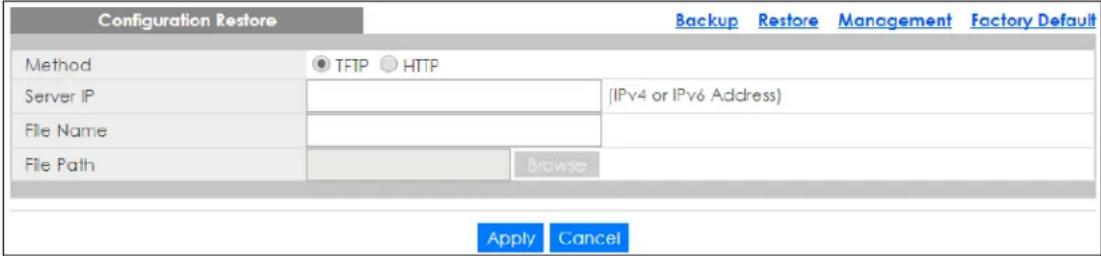
The following table describes the labels under Configuration Restore.
Table 193 Maintenance > Configuration > Restore
| LABEL DESCRIPTION | |
| Configuration Restore | |
| Method | Choose HTTP to use the Web Configurator for restoring the configuration file. Alternatively, choose TFTP to download the snapshot from a TFTP server. |
| Server IP | To download from a TFTP server, enter the TFTP server IP address. |
| File Name Enter the name of the configuration file on the TFTP server. | |
| File Path | Browse to the path on your computer to upload the configuration you want to restore. |
| Apply | Click Apply to save the changes. |
| Cancel | Click Cancel to discard the changes. |
33.4.2 Restore the configuration from a file on a server
Follow the steps below to restore the configuration from a server.
- In Method, choose TFTP.
- In Server IP, enter the TFTP server IP address.
- In File Name, enter the name of the configuration file on the TFTP server.
- Click Apply to restore to the chosen file as the running configuration. OR
Click Cancel to discard the changes.
33.4.3 Restore the configuration from a file on your computer
Follow the steps below to restore the configuration from a file on your computer.
- In Method, choose HTTP.
- In File Path, click Browse to display the Choose File screen from which you can locate the configuration file in the cfg format on your computer.
- Click Apply to restore to the chosen file as the running configuration. OR
Click Cancel to discard the changes.
33.5 Manage Configuration Files
33.5.1 Overview
The Configuration Management screen provides instant access to the configuration files of your Switch. You can overwrite the startup and backup configurations with the current running, startup, or backup configuration file.
Click Maintenance > Configuration > Management to display the screen as shown next. Use this screen to replace startup and backup configuration files.
Figure 261 Maintenance > Configuration > Management
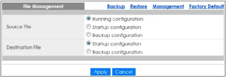
Follow the steps to overwrite the startup or backup configuration file.
- In Source File, select the file to be used as a reference.
- In Destination File, select the file to be overwritten.
- Click Apply to restore to overwrite the destination file with the source file. OR
Click Cancel to discard the changes.
33.6 Reset to Factory Defaults
33.6.1 Overview
You can reset the Switch to it's original settings.
Click Maintenance > Configuration > Factory Default to display the screen as shown next. Use this screen to reset the Switch back to factory defaults.
Table 194 Maintenance > Configuration > Factory Default

33.6.2 Reset the Switch to Factory Defaults
Follow the steps below to reset the Switch back to factory defaults.
- Click Restore.
- Click OK to reset all Switch configurations to the factory defaults. Wait for the Switch to restart. This takes up to 2 minutes.
OR
Click Cancel to discard the changes.
Note: If you want to access the Switch Web Configurator again, you may need to change the IP address of your computer to be in the same subnet as that of the default Switch IP address (192.168.1.1).
33.7 Network Diagnostics
Use the network utilities to perform diagnostics.
33.7.1 Port Test
Click Maintenance > Diagnostics > Port Test > Cable Diag in the navigation panel to open this screen. Use this screen to perform an internal loop-back test on an Ethernet port.
Note: The Switch measures the cable length by sending an electric signal through the cable and reading the signal that is reflected back. To prevent possible interference from a connected device, it is suggested that you disconnect the other end of the Ethernet cable which is connected to the specified port.
Figure 262 Maintenance > Diagnostics > Port Test > Cable Diag
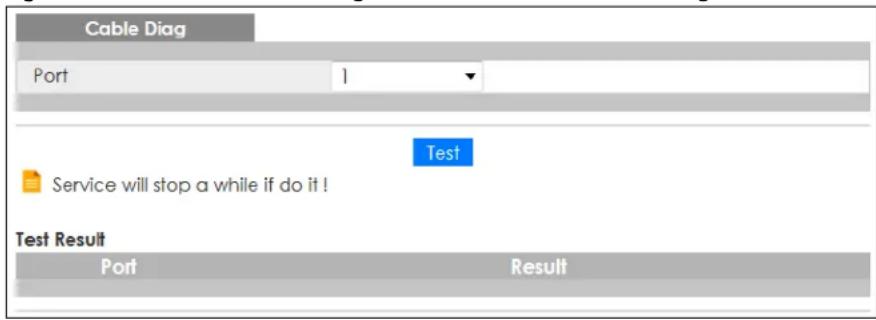
Follow the steps to perform the port test.
- In Port Test, select the port number from the Port drop-down list.
- Click Test to start the port test.
The test results are displayed in Test Results.
33.7.2 IPv4 Ping Test
Click Maintenance > Diagnostics > PING > IPv4 in the navigation panel to open this screen. Use this screen to ping an IPv4 server.
Figure 263 Maintenance > Diagnostics > PING > IPv4
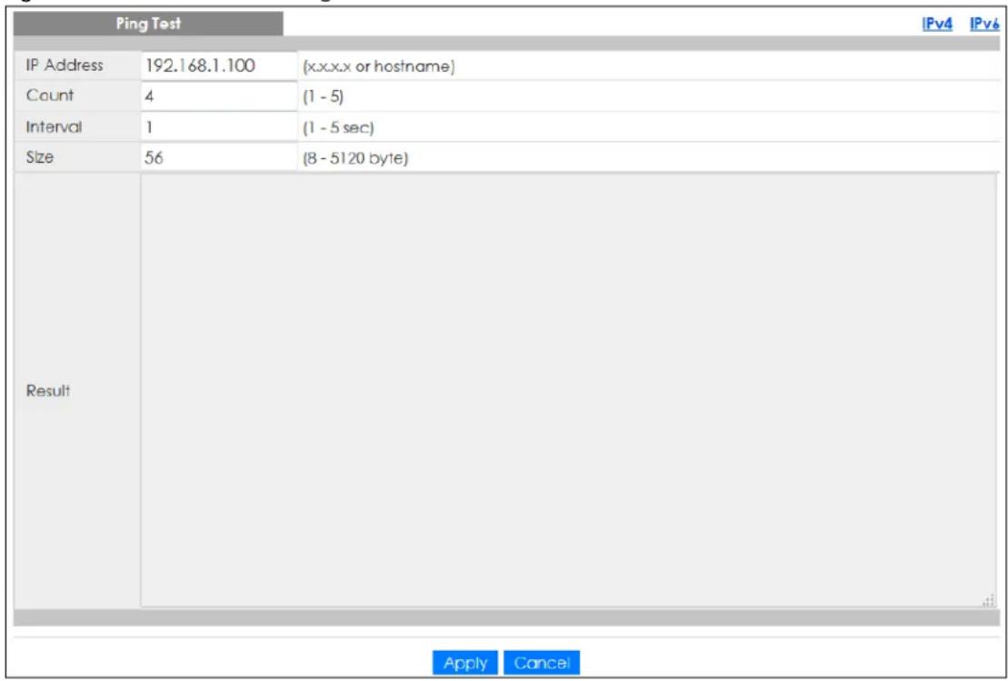
The following table describes the labels under Ping Test.
Table 195 Maintenance > Diagnostics > PING > IPv4
| LABEL DESCRIPTION | |
| Ping Test | |
| IP Address Enter the address of the target host server. | |
| Count | Enter the number of ping packets to send. The range is 1 to 5 packets; the default count is 4. |
| Interval | Enter the time in seconds between sending ping packets. The range is 1 to 5 seconds; the default is 1 second. |
| Size | Enter the individual packet size in bytes. The range is 8 to 5120 bytes; the default is 56 bytes. |
| Apply | Click Apply to save the changes. |
| Cancel | Click Cancel to discard the changes. |
Follow the steps to perform a ping test.
- In IP Address, enter the IPv4 address.
- In Count, enter the number of ping packets.
- In Interval, enter the time interval in seconds.
- In Size, enter the packet size in bytes
- Click Apply to perform the ping test.
OR
Click Cancel to discard the changes.
The test results are displayed in Results.
33.7.3 IPv6 Ping Test
Click Maintenance > Diagnostics > PING > IPv6 in the navigation panel to open this screen. Use this screen to ping an IPv6 server.
Figure 264 Maintenance > Diagnostics > PING > IPv6
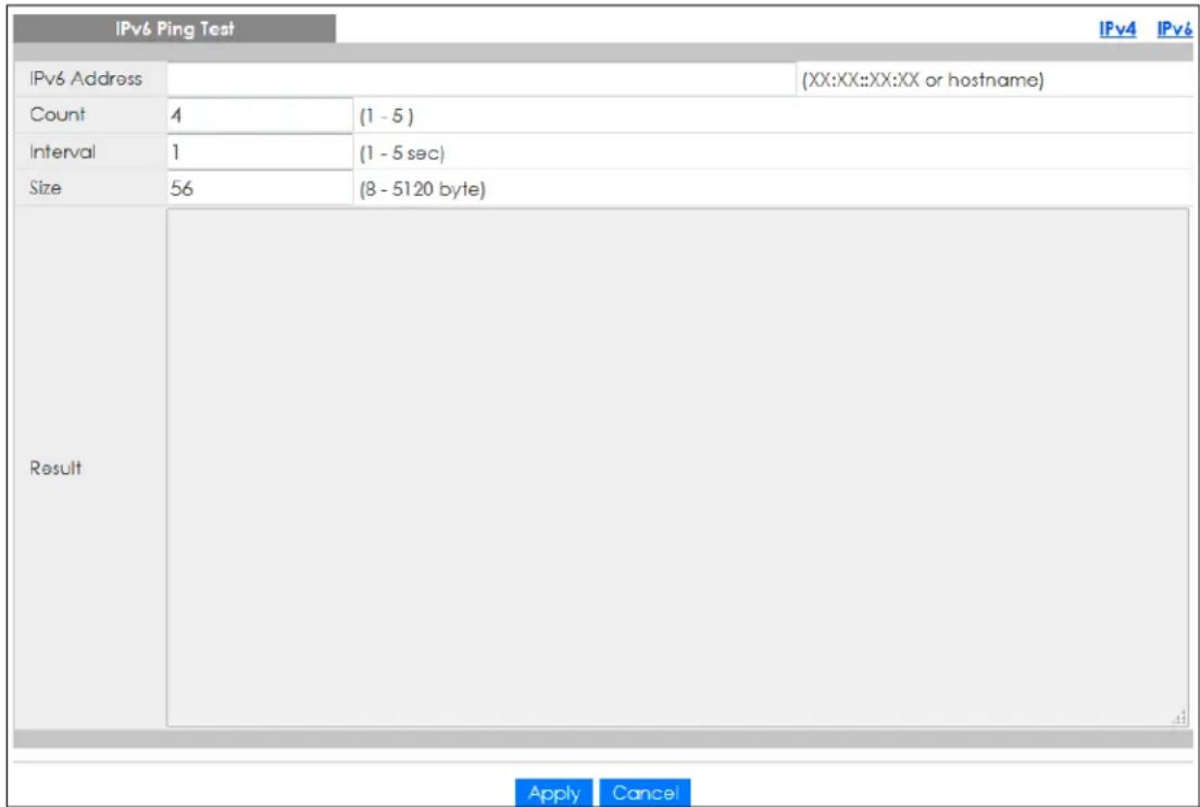
The following table describes the labels in IPv6 Ping Test.
Table 196 Maintenance > Diagnostics > PING > IPv6
| LABEL DESCRIPTION | |
| IPv6 Ping Test | |
| IPv6 Address Enter | the address of the target host server. |
| Count | Enter the number of ping packets to send. The range is 1 to 5 packets; the default count is 4. |
| Interval | Enter the time in seconds between sending ping packets. The range is 1 to 5 seconds; the default is 1 second. |
| Size | Enter the individual packet size in bytes. The range is 8 to 5120 bytes; the default is 56 bytes. |
| Apply | Click Apply to save the changes. |
| Cancel | Click Cancel to discard the changes. |
Follow the steps to perform a ping test.
- In IPv6 Address, enter the IPv6 address.
- In Count, enter the number of ping packets.
- In Interval, enter the time interval in seconds.
- In Size, enter the packet size in bytes.
- Click Apply to perform the ping test.
OR
Click Cancel to discard the changes.
The test results are displayed in Results.
33.7.4 Trace Route
Click Maintenance > Diagnostics > Trace > Trace Route in the navigation panel to open this screen. Use this screen to print the route that IP packets take to a network host.
Figure 265 Maintenance > Diagnostics > Trace > Trace Route
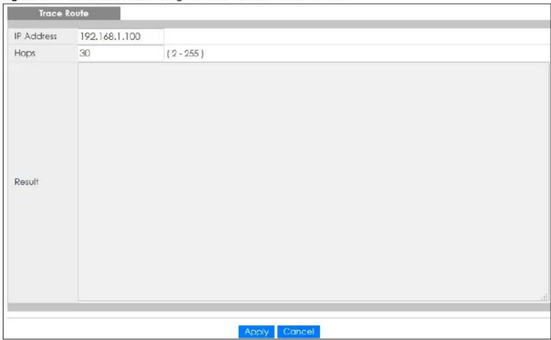
The following table describes the labels in Trace Route.
Table 197 Maintenance > Diagnostics > Trace > Trace Route
| LABEL DESCRIPTION | |
| Trace Route | |
| IP Address Enter the address of the target host server. | |
| Hops | Enter the maximum number of time-to-live or hops used in outgoing probe packets. The range is 2 to 255 packets; the default is 30 hops. |
| Apply | Click Apply to save the changes. |
| Cancel | Click Cancel to discard the changes. |
Follow the steps to perform a trace route.
- In IP Address, enter the IPv6 address.
- In Hops, enter the number of hops.
- Click Apply to perform the test.
OR
Click Cancel to discard the changes.
The test results are displayed in Result.
33.8 Reboot
33.8.1 Overview
You can reboot the Switch from the Web Configurator.
Click Maintenance > Reboot in the navigation panel to open this screen. Use this screen to restart the Switch without physically turning the power off.
Figure 266 Maintenance > Reboot
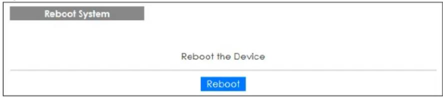
33.8.2 Reboot the Switch
Follow the steps below to restart the Switch.
- Click Reboot.
- Click OK and then wait for the Switch to restart. This process takes up to 2 minutes and does not affect the Switch's configuration.
OR
Click Cancel to discard the changes.
CHAPTER 34
Troubleshooting
This chapter offers some suggestions to solve problems you might encounter. The potential problems are divided into the following categories.
• Power, Hardware Connections, and LEDs
- Switch Access and Login
- Switch Configuration
34.1 Power, Hardware Connections, and LEDs
The Switch does not turn on. None of the LEDs turn on.
1 Make sure the Switch is turned on (in DC models or if the DC power supply is connected in AC/DC models).
2 Make sure you are using the power adapter or cord included with the Switch.
3 Make sure the power adapter or cord is connected to the Switch and plugged in to an appropriate power source. Make sure the power source is turned on.
4 Turn the Switch off and on (in DC models or if the DC power supply is connected in AC/DC models).
5 Disconnect and re-connect the power adapter or cord to the Switch (in AC models or if the AC power supply is connected in AC/DC models).
6 If the problem continues, contact the vendor.
One of the LEDs does not behave as expected.
1 Make sure you understand the normal behavior of the LED. See Section 3.3 on page 41.
2 Check the hardware connections. See Chapter 2 on page 25.
3 Inspect your cables for damage. Contact the vendor to replace any damaged cables.
4 Turn the Switch off and on (in DC models or if the DC power supply is connected in AC/DC models).
5 Disconnect and re-connect the power adapter or cord to the Switch (in AC models or if the AC power
supply is connected in AC/DC models).
6 If the problem continues, contact the vendor.
34.2 Switch Access and Login
I forgot the IP address for the Switch.
1 The default in-band IP address is 192.168.1.1 or http://DHCP-assigned IP (when connecting to a DHCP server).
2 If this does not work, you have to reset the device to its factory defaults. See Section 3.4 on page 43 or Section 33.6 on page 244.
I forgot the user name and/or password.
1 The default user name is admin and the default password is 1234.
2 If this does not work, you have to reset the device to its factory defaults. See Section 3.4 on page 43 or Section 33.6 on page 244.
I cannot see or access the Login screen in the Web Configurator.
1 Make sure you are using the correct IP address.
• The default in-band IP address is 192.168.1.1.
- If you changed the IP address, use the new IP address.
- If you changed the IP address and have forgotten it, see the troubleshooting suggestions for I forgot the IP address for the Switch.
2 Check the hardware connections, and make sure the LEDs are behaving as expected. See Chapter 2 on page 25.
3 Make sure your Internet browser does not block pop-up windows and has JavaScripts and Java enabled.
4 Make sure your computer is in the same subnet as the Switch. (If you know that there are routers between your computer and the Switch, skip this step.)
5 Reset the device to its factory defaults, and try to access the Switch with the default IP address. See Section 3.4 on page 43 or Section 33.6 on page 244.
6 If the problem continues, contact the vendor, or try one of the advanced suggestions.
Advanced Suggestions
- Try to access the Switch using another service, such as HTTPS. If you can access the Switch, check the remote management settings to find out why the Switch does not respond to HTTP.
I can see the Login screen, but I cannot log in to the Switch.
1 Make sure you have entered the user name and password correctly. The default user name is admin, and the default password is 1234. These fields are case-sensitive, so make sure [Caps Lock] is not on.
2 Check that you have enabled logins for HTTP. If you have configured a secured client IP address, your computer's IP address must match it. Refer to the chapter on access control for details.
3 Disconnect and re-connect the cord to the Switch.
4 If this does not work, you have to reset the device to its factory defaults. See Section 3.4 on page 43 or Section 33.6 on page 244.
Pop-up Windows, JavaScripts and Java Permissions
In order to use the Web Configurator you need to allow:
- Web browser pop-up windows from your device.
- JavaScripts (enabled by default).
- Java permissions (enabled by default).
34.3 Switch Configuration
I lost my configuration settings after I restart the Switch.
Make sure you save your configuration into the Switch's non-volatile memory each time you make changes. Click Save at the top right corner of the Web Configurator to save the configuration permanently. See also Section 5.3.1 on page 52 for more information about how to save your configuration.

Refresh


Status

Logout

Help
APPENDIX A
Customer Support
In the event of problems that cannot be solved by using this manual, you should contact your vendor. If you cannot contact your vendor, then contact a Zyxel office for the region in which you bought the device.
For Zyxel Communication offices, see https://service-provider.zyxel.com/global/en/contact-us for the latest information.
For Zyxel Network offices, see https://www.zyxel.com/index.shtml for the latest information.
Please have the following information ready when you contact an office.
Required Information
- Product model and serial number.
- Warranty Information.
- Date that you received your device.
- Brief description of the problem and the steps you took to solve it.
Corporate Headquarters (Worldwide)
Taiwan
• Zyxel Communications Corporation
- https://www.zyxel.com
Asia
China
• Zyxel Communications (Shanghai) Corp.
Zyxel Communications (Beijing) Corp.
Zyxel Communications (Tianjin) Corp.
- https://www.zyxel.com/cn/zh/
India
• Zyxel Technology India Pvt Ltd.
- https://www.zyxel.com/in/en/
Kazakhstan
• Zyxel Kazakhstan
- https://www.zyxel.kz
Korea
• Zyxel Korea Corp.
- http://www.zyxel.kr
Malaysia
• Zyxel Malaysia Sdn Bhd.
- http://www.zyxel.com.my
Pakistan
• Zyxel Pakistan (Pvt.) Ltd.
- http://www.zyxel.com.pk
Philippines
• Zyxel Philippines
- http://www.zyxel.com.ph
Singapore
• Zyxel Singapore Pte Ltd.
- http://www.zyxel.com.sg
Taiwan
• Zyxel Communications Corporation
- https://www.zyxel.com/tw/zh/
Thailand
• Zyxel Thailand Co., Ltd.
- https://www.zyxel.com/th/th/
Vietnam
• Zyxel Communications Corporation-Vietnam Office
- https://www.zyxel.com/vn/vi
Europe
Belarus
- Z y x e l B Y
- https://www.zyxel.by
Bulgaria
• Z y x e l България
- https://www.zyxel.com/bg/bg/
Czech Republic
• Zyxel Communications Czech s.r.o
- https://www.zyxel.com/cz/cs/
Denmark
• Zyxel Communications A/S
- https://www.zyxel.com/dk/da/
Finland
• Zyxel Communications
- https://www.zyxel.com/fi/fi/
France
• Zyxel France
- https://www.zyxel.fr
Germany
• Zyxel Communications Italy
- https://www.zyxel.com/it/it/
Netherlands
- Zyxel Benelux
- https://www.zyxel.com/nl/nl/
Norway
• Zyxel Communications
- https://www.zyxel.com/no/no/
Poland
• Zyxel Communications Poland
- https://www.zyxel.com/pl/pl/
Romania
• Zyxel Romania
- https://www.zyxel.com/ro/ro
Russia
• Zyxel Communications Czech s.r.o. organizacna zlozka
- https://www.zyxel.com/sk/sk/
Spain
• Zyxel Turkey A.S.
- https://www.zyxel.com/tr/tr/
UK
• Zyxel Communications UK Ltd.
- https://www.zyxel.com/uk/en/
Ukraine
• Zyxel Ukraine
- http://www.ua.zyxel.com
South America
Argentina
• Zyxel Communications Corporation
- https://www.zyxel.com/co/es/
Brazil
• Zyxel Communications Brasil Ltda.
- https://www.zyxel.com/br/pt/
Colombia
• Zyxel Communications Corporation
- https://www.zyxel.com/co/es/
Ecuador
• Zyxel Communications Corporation
- https://www.zyxel.com/co/es/
South America
• Zyxel Communications Corporation
- https://www.zyxel.com/co/es/
Middle East
Israel
• Zyxel Communications Corporation
- http://il.zyxel.com/
North America
USA
• Zyxel Communications, Inc. – North America Headquarters
- https://www.zyxel.com/us/en/
APPENDIX B
Legal Information
Copyright
Copyright © 2022 by Zyxel and/or its affiliates.
The contents of this publication may not be reproduced in any part or as a whole, transcribed, stored in a retrieval system, translated into any language, or transmitted in any form or by any means, electronic, mechanical, magnetic, optical, chemical, photocopying, manual, or otherwise, without the prior written permission of Zyxel and/or its affiliates.
Published by Zyxel and/or its affiliate. All rights reserved.
Disclaimer
Zyxel does not assume any liability arising out of the application or use of any products, or software described herein. Neither does it convey any license under its patent rights nor the patent rights of others. Zyxel further reserves the right to make changes in any products described herein without notice. This publication is subject to change without notice.
Regulatory Notice and Statement (Class A)
Model List: GS1900-8 (Revision B1), GS1900-8HP (Revision A1, B2), GS1900-10HP (Revision B1), GS1900-16 (Revision B1), GS1900-24, GS1900-24E (Revision B1), GS1900-24EP, GS1900-24HP/GS1900-24HPv2, GS1900-48, GS1900-48HP/GS1900-48HPv2
United States of America

The following information applies if you use the product within USA area.
Federal Communications Commission (FCC) EMC Statement
- This device complies with Part 15 of FCC rules. Operation is subject to the following two conditions:
(1) This device may not cause harmful interference.
(2) This device must accept any interference received, including interference that may cause undesired operations.
- Changes or modifications not expressly approved by the party responsible for compliance could void the user's authority to operate the equipment.
- This equipment has been tested and found to comply with the limits for a Class A digital device, pursuant to part 15 of the FCC Rules. These limits are designed to provide reasonable protection against harmful interference when the equipment is operated in a commercial environment. This equipment generates, uses, and can radiate radio frequency energy and, if not installed and used in accordance with the instruction manual, may cause harmful interference to radio communications. Operation of this equipment in a residential area is likely to cause harmful interference in which case the user will be required to correct the interference at his own expense.
Canada
The following information applies if you use the product within Canada area
Industry Canada ICES statement
CAN ICES-3 (A)/NMB-3(A)
European Union and United Kingdom

The following information applies if you use the product within the European Union and United Kingdom.
EMC statement
WARNING: This equipment is compliant with Class A of EN55032. In a residential environment this equipment may cause radio interference.
List of National Codes
| COUNTRY ISO 3166 2 LETTER CODE COUNTRY ISO 3166 2 LETTER CODE | |||
| Austria AT Liechtenstein LI | |||
| Belgium BE Lithuania LT | |||
| Bulgaria BG Luxembourg LU | |||
| Croatia HR Malta | MT | ||
| Cyprus | CY | Netherlands | NL |
| Czech Republic | CZ Norway NO | ||
| Denmark | DK | Poland | PL |
| Estonia | EE Portugal | PT | |
| Finland | FI | Romania RO | |
| France | FR Serbia | RS | |
| Germany | DE Slovakia | SK | |
| Greece GR Slovenia | SI | ||
| Hungary | HU | Spain | ES |
| Iceland | IS | Sweden SE | |
| Ireland | IE | Switzerland | CH |
| Italy | IT | Turkey | TR |
| Latvia | LV United Kingdom | GB | |
Safety Warnings
- Do not use this product near water, for example, in a wet basement or near a swimming pool.
- Do not expose your device to dampness, dust or corrosive liquids.
- Do not store things on the device.
- Do not obstruct the device ventilation slots as insufficient airflow may harm your device. For example, do not place the device in an enclosed space such as a box or on a very soft surface such as a bed or sofa.
- Do not install, use, or service this device during a thunderstorm. There is a remote risk of electric shock from lightning.
- Connect ONLY suitable accessories to the device.
- Do not open the device or unit. Opening or removing covers can expose you to dangerous high voltage points or other risks. Only qualified service personnel should service or disassemble this device. Please contact your vendor for further information.
- Make sure to connect the cables to the correct ports.
- Place connecting cables carefully so that no one will step on them or stumble over them.
• Always disconnect all cables from this device before servicing or disassembling.
- Do not remove the plug and connect it to a power outlet by itself; always attach the plug to the power adaptor first before connecting it to a power outlet.
- Do not allow anything to rest on the power adaptor or cord and do NOT place the product where anyone can walk on the power adaptor or cord.
- Please use the provided or designated connection cables/power cables/ adaptors. Connect it to the right supply voltage (for example, 110V AC in North America or 230V AC in Europe). If the power adaptor or cord is damaged, it might cause electrocution. Remove it from the device and the power source, repairing the power adapter or cord is prohibited. Contact your local vendor to order a new one.
- Do not use the device outside, and make sure all the connections are indoors. There is a remote risk of electric shock from lightning.
- Caution: Risk of explosion if battery is replaced by an incorrect type, dispose of used batteries according to the instruction. Dispose them at the applicable collection point for the recycling of electrical and electronic device. For detailed information about recycling of this product, please contact your local city office, your household waste disposal service or the store where you purchased the product.
• Use ONLY power wires of the appropriate wire gauge for your device. Connect it to a power supply of the correct voltage.
- Fuse Warning! Replace a fuse only with a fuse of the same type and rating.
• The POE (Power over Ethernet) devices that supply or receive power and their connected Ethernet cables must all be completely indoors.
- The following warning statements apply, where the disconnect device is not incorporated in the device or where the plug on the power supply cord is intended to serve as the disconnect device,
- For permanently connected devices, a readily accessible disconnect device shall be incorporated external to the device;
- For pluggable devices, the socket-outlet shall be installed near the device and shall be easily accessible.
- This equipment must be grounded by qualified service personnel. Never defeat the ground conductor or operate the equipment in the absence of a suitably installed ground conductor. Contact the appropriate electrical inspection authority or an electrician if you are uncertain that suitable grounding is available.
- If your device has an earthing screw (frame ground), connect the screw to a ground terminal using an appropriate AWG ground wire. Do this before you make other connections.
• If your device has no earthing screw, but has a 3-prong power plug, make sure to connect the plug to a 3-hole earthed socket.
- When connecting or disconnecting power to hot-pluggable power supplies, if offered with your system, observe the following guidelines:
- Install the power supply before connecting the power cable to the power supply.
- Unplug the power cable before removing the power supply.
- If the system has multiple sources of power, disconnect power from the system by unplugging all power cables from the power supply.
• CLASS 1 LASER PRODUCT (for products with mini-GBIC slots or laser products, such as fiber-optic transceiver and GPON products).
- PRODUCT COMPLIES WITH 21 CFR 1040.10 AND 1040.11. (for products with mini-GBIC slots or laser products, such as fiber-optic transceiver and GPON products)
• APPAREIL À LASER DE CLASS 1 (for products with mini-GBIC slots or laser products, such as fiber-optic transceiver and GPON products).
• PRODUIT CONFORME SELON 21 CFR 1040.10 ET 1040.11. (for products with mini-GBIC slots or laser products, such as fiber-optic transceiver and GPON products)
Environment Statement
Disposal and Recycling Information
The symbol below means that according to local regulations your product and/or its battery shall be disposed of separately from domestic waste. If this product is end of life, take it to a recycling station designated by local authorities. At the time of disposal, the separate collection of your product and/or its battery will help save natural resources and ensure that the environment is sustainable development.
Regulatory Notice and Statement (Class B)
Model List: GS1900-8, GS1900-8HP (Revision B1), GS1900-10HP, GS1900-16, GS1900-24E
UNITED STATES of AMERICA

The following information applies if you use the product within USA area.
FCC EMC Statement
• The device complies with Part 15 of FCC rules. Operation is subject to the following two conditions:
(1) This device may not cause harmful interference, and
(2) This device must accept any interference received, including interference that may cause undesired operation.
- Changes or modifications not expressly approved by the party responsible for compliance could void the user's authority to operate the device.
- This product has been tested and complies with the specifications for a Class B digital device, pursuant to Part 15 of the FCC Rules. These limits are designed to provide reasonable protection against harmful interference in a residential installation. This device generates, uses, and can radiate radio frequency energy and, if not installed and used according to the instructions, may cause harmful interference to radio communications. However, there is no guarantee that interference will not occur in a particular installation.
- If this device does cause harmful interference to radio or television reception, which is found by turning the device off and on, the user is encouraged to try to correct the interference by one or more of the following measures:
- Reorient or relocate the receiving antenna
- Increase the separation between the devices
- Connect the equipment to an outlet other than the receiver's
- Consult a dealer or an experienced radio/TV technician for assistance
CANADA
The following information applies if you use the product within Canada area
Industry Canada ICES statement
CAN ICES-3 (B)/NMB-3(B)
EUROPEAN UNION and UNITED KINGDOM

The following information applies if you use the product within the European Union and United Kingdom.
List of national codes
| COUNTRY ISO 3166 2 LETTER CODE COUNTRY ISO 3166 2 LETTER CODE | |||
| Austria AT Liechtenstein LI | |||
| Belgium BE Lithuania LT | |||
| Bulgaria BG Luxembourg LU | |||
| Croatia HR Malta | MT | ||
| Cyprus | CY | Netherlands | NL |
| Czech Republic | CZ Norway NO | ||
| Denmark | DK | Poland | PL |
| Estonia | EE Portugal | PT | |
| Finland | FI | Romania RO | |
| France | FR Serbia | RS | |
| Germany | DE Slovakia | SK | |
| Greece GR Slovenia | SI | ||
| Hungary | HU | Spain | ES |
| Iceland | IS | Switzerland | CH |
| Ireland | IE | Sweden SE | |
| Italy | IT | Turkey | TR |
| Latvia | LV United Kingdom | GB | |
Safety Warnings
- Do not use this product near water, for example, in a wet basement or near a swimming pool.
- Do not expose your device to dampness, dust or corrosive liquids.
- Do not store things on the device.
- Do not obstruct the device ventilation slots as insufficient airflow may harm your device. For example, do not place the device in an enclosed space such as a box or on a very soft surface such as a bed or sofa.
- Do not install, use, or service this device during a thunderstorm. There is a remote risk of electric shock from lightning.
- Connect ONLY suitable accessories to the device.
- Do not open the device or unit. Opening or removing covers can expose you to dangerous high voltage points or other risks. ONLY qualified service personnel should service or disassemble this device. Please contact your vendor for further information.
- Make sure to connect the cables to the correct ports.
- Place connecting cables carefully so that no one will step on them or stumble over them.
• Always disconnect all cables from this device before servicing or disassembling. - Do not remove the plug and connect it to a power outlet by itself; always attach the plug to the power adaptor first before connecting it to a power outlet.
- Do not allow anything to rest on the power adaptor or cord and do NOT place the product where anyone can walk on the power adaptor or cord.
- Please use the provided or designated connection cables/power cables/ adaptors. Connect it to the right supply voltage (for example, 110V AC in North America or 230V AC in Europe). If the power adaptor or cord is damaged, it might cause electrocution. Remove it from the device and the power source, repairing the power adapter or cord is prohibited. Contact your local vendor to order a new one.
- Do not use the device outside, and make sure all the connections are indoors. There is a remote risk of electric shock from lightning.
- CAUTION: Risk of explosion if battery is replaced by an incorrect type, dispose of used batteries according to the instruction. Dispose them at the applicable collection point for the recycling of electrical and electronic devices. For detailed information about recycling of this product, please contact your local city office, your household waste disposal service or the store where you purchased the product.
- The following warning statements apply, where the disconnect device is not incorporated in the device or where the plug on the power supply cord is intended to serve as the disconnect device.
- For permanently connected devices, a readily accessible disconnect device shall be incorporated external to the device;
- For pluggable devices, the socket-outlet shall be installed near the device and shall be easily accessible.
• CLASS 1 LASER PRODUCT (for products with mini-GBIC slots or laser products, such as fiber-optic transceiver and GPON products).
- PRODUCT COMPLIES WITH 21 CFR 1040.10 AND 1040.11. (for products with mini-GBIC slots or laser products, such as fiber-optic transceiver and GPON products)
• APPAREIL À LASER DE CLASS 1 (for products with mini-GBIC slots or laser products, such as fiber-optic transceiver and GPON products).
• PRODUIT CONFORME SELON 21 CFR 1040.10 ET 1040.11. (for products with mini-GBIC slots or laser products, such as fiber-optic transceiver and GPON products)
Environment Statement
ErP (Energy-related Products)
Zyxel products put on the EU and United Kingdom market in compliance with the requirement of the European Parliament and the Council published Directive 2009/125/EC and UK regulation establishing a framework for the setting of ecodesign requirements for energy-related products (recast), so called as "ErP Directive (Energy-related Products directive) as well as ecodesign requirement laid down in applicable implementing measures, power consumption has satisfied regulation requirements which are:
• Network standby power consumption < 8W, and/or
- Off mode power consumption < 0.5 W ,and/or
- Standby mode power consumption < 0.5W .
Disposal and Recycling Information
The symbol below means that according to local regulations your product and/or its battery shall be disposed of separately from domestic waste. If this product is end of life, take it to a recycling station designated by local authorities. At the time of disposal, the separate collection of your product and/or its battery will help save natural resources and ensure that the environment is sustainable development.
Various symbols are used in this product to ensure correct usage, to prevent danger to the user and others, and to prevent properly damage. The meaning of these symbols are described below. It is important that you read these descriptions thoroughly and fully understand the contents.
Explanation of the Symbols
| SYMBOL EXPLANATION | |
 | Alternating current (AC):AC is an electric current in which the flow of electric charge periodically reverses direction. |
 | Direct current (DC):DC if the unidirectional flow or movement of electric charge carriers. |
 | Earth; ground:A wiring terminal intended for connection of a Protective Earthing Conductor. |
 | Class II equipment:The method of protection against electric shock in the case of class II equipment is either double insulation or reinforced insulation. |
Viewing Certifications
Go to http://www.zyxel.com to view this product's documentation and certifications.
Zyxel Limited Warranty
Zyxel warrants to the original end user (purchaser) that this product is free from any defects in material or workmanship for a specific period (the Warranty Period) from the date of purchase. The Warranty Period varies by region. Check with your vendor and/or the authorized Zyxel local distributor for details about the Warranty Period of this product. During the warranty period, and upon proof of purchase, should the product have indications of failure due to faulty workmanship and/or materials. Zyxel will, at its discretion, repair or replace the defective products or components without charge for either parts or labor, and to whatever extent it shall deem necessary to restore the product or components to proper operating condition. Any replacement will consist of a new or re-manufactured functionally equivalent product of equal or higher value, and will be solely at the discretion of Zyxel. This warranty shall not apply if the product has been modified, misused, tampered with, damaged by an act of God, or subjected to abnormal working conditions.
Note
Repair or replacement, as provided under this warranty, is the exclusive remedy of the purchaser. This warranty is in lieu of all other warranties, express or implied, including any implied warranty of merchantability or fitness for a particular use or purpose. Zyxel shall in no event be held liable for indirect or consequential damages of any kind to the purchaser.
To obtain the services of this warranty, contact your vendor. You may also refer to the warranty policy for the region in which you bought the device at http://www.zyxel.com/web/support_warranty_info.php.
Registration
Register your product on-line at www.zyxel.com to receive email notices of firmware upgrades and related information.
Trademarks
The trademarks mentioned in this publication are used for identification purposes only and may be properties of their respective owners.
Open Source Licenses
This product may contain in part some free software distributed under GPL license terms and/or GPL like licenses. To request the source code covered under these licenses, please go to: https://www.zyxel.com/form/gpl_oss_software_notice.shtml
Index
Numbers
10/100/1000 Mbps gigabit Ethernet 33
1000Base-T Ethernet port 33
19-inch rack 28
802.1x port authentication 89
A
AAA (authentication, authorization and accounting) 216
AC power ground 39
access 50
ACKnowledgment (ACK) 215
Add Filtering MAC screen 151
Add OUI screen 147
administrator password 51
air circulation
desktop installation 26
for cooling 25
altitude 193
application
backbone 21
bridging 21
fiber-optic uplink 21
IEEE 802.1Q VLAN 22
PoE 20
Auth Method screen 216
Authenticated Hosts screen 116
authentication 216
authentication failure traps 229
authentication method 232 select 232
authentication password 228
authentication protocol 228 display 227
authorized technician install the Switch 25
auto configuration 75, 121
auto-crossover (auto-MDI/MDI-X) port 33
auto-negotiating port 33
B
back up configuration files
to a server 242
to your computer 242
back up log files
to a server 242
to your computer 242
backbone 21
backup configuration file overwrite 244
Backup screen 241
bandwidth contention
alleviate 21
Bandwidth Control screen 83
Bandwidth Utilization screen 80
BPDU (Bridge Protocol Data Unit) 180
bracket
for mounting 28
bridge protocol data unit (BPDU) 178
broadcast 100, 169
broadcast packet 136
broadcast storm control 135
bug fixes 238
button
PoE mode 36
RESET 43
RESTORE 43
C
Cable Diag screen 245
cable length
measure 245
certifications 262
viewing 264
CIST Instance screen 104, 180
CIST Port screen 105, 181
Class of Service (CoS) 201
clearance
for ventilation hole 25
Switch installation 25
Common and Internal Spanning Tree (CIST) 104
Community screen 224
comparison table
hardware version 18
Switch 19
configuration file
back up 241
manage 243
restore 242
Configuration menu
Web Configurator 55
Configuration Restore screen 242
connection speed
SFP transceiver 34
contact information 253
cookies 50
Coordinated Universal Time (UTC) format 240
copyright 258
customer support 253
D
Daylight Saving Time 122
Denial of Service (DoS) attack 213
destination lookup failure (DLF) 135
DHCP setting 121
DHCP state 74
DHCPv6 client 23, 121
diagnostics
perform 245
disclaimer 258
DNS (Domain Name System) 63, 65, 75, 121
DNS server 75
DoS attack 213
types 215
DoS protection 213
Dynamic Host Configuration Protocol (DHCP) 74
dynamic link aggregation 152
Dynamic MAC Age screen 151
dynamic router port 103
E
earth resistance
specification 39
earthing terminal
building 39
EEE settings
VLAN port 144
Egress Global Burst screen 134
egress port 83, 142
EIA rack 28
EIA standard size 28
electrical inspection authority 40
electrical regulation 39
electrician 40
electrocution
protect from 38
electrostatic discharge (ESD) 34
encryption protocol
display 227
endpoint 195
Energy-Efficient Ethernet (EEE) setting 127
Error Disable screen 118, 231
ESD preventive wrist strap 34
ESD protection 39
Ethernet port 33
default setting 33
loop-back test 245
F
factory-default configuration file reload 43
FCC interference statement 258
fiber-optic cable 33 connecting 35 removal 35
File Management screen 243
Filtering MAC screen 150
FINish (FIN) packet 215
Firefox 50
firmware current version 62
firmware update 238
firmware upgrade steps 238
flash (permanent) memory 222
flash partition number 240
flow control state 126
forbidden router port 103, 172, 173
frame broadcast domain share 23
front panel 31
FTP 24
full duplex 33
G
gap screw insertion 27
gateway 75
Getting Start icon 61
Getting Start screen 61
Getting Started screen 51
gigabit Ethernet 22
Gigabit Ethernet (GbE) 17
Global screen 143, 235 voice VLAN 145
Google Chrome 50
ground cable specification 39
ground wire 38
grounding safety measure 38
grounding bar 39
grounding electrode 39
grounding screw 38
grounding terminal 39
guest VLAN 89
guest VLAN example 143
guest voice media 195
H
half duplex 33
hardware installation 25
hardware overview 31
host server IPv4 address 246 IPv6 address 247
HTML5 support 50
HTTP 23
HTTP mode 232
HTTP screen 231
HTTPS certificate 233
HTTPS screen 232
|
ICMPv6 23
IEEE 802.1D
Spanning Tree Protocol 177
IEEE 802.1D priority level 195
IEEE 802.1Q-2003 194, 195
IEEE 802.1s
Multiple Spanning Tree Protocol 177
IEEE 802.1w
Rapid Spanning Tree Protocol 177
IEEE 802.3af PoE 81, 129
IEEE 802.3at High PoE 81, 129
IGMP (Internet Group Management Protocol) 100, 169
IGMP Edit screen 171
IGMP Group screen 102
IGMP Port Throttling screen 174, 176
IGMP Profile screen 173, 174
IGMP Querier version 171
IGMP Router Edit screen 172
IGMP Router screen 103
IGMP screen 100
IGMP state 171
IGMP Statistics screen 101
IGMP VLAN screen 170
Image Select screen 240
ingress filter 88
ingress filtering 141
ingress port 83, 195
installation
air circulation 25
desktop 26
freestanding 26
precautions 29
installation requirement
rack mounting 28
wall mounting 27
installation scenarios 25
Internet Control Message Protocol (ICMP) 215
Internet Explorer 50
Internet Protocol version 6, see IPv6
introduction 17
IP address 121
default 74, 120
TFTP server 238
LACP Port screen 156, 157
LAG Management screen 153, 154
LAG Port screen 155
LAG port settings
view 155
latitude 192
LED
Link/ACT 36
PoE 36
SYS 43
LED description 41
LEDs 41
link aggregation (trunking) 95, 152
Link Aggregation Control Protocol (LACP) 153
Link Aggregation screen 95
link aggregation setting 70
Link Layer Discovery Protocol (LLDP) 110
Link Layer Discovery Protocol (LLDP) screens 186
link status 78
Link/ACT LED 36
LLDP global statistics 110
LLDP Port screen 188
LLDP port settings
inspect and configure 186
LLDP port statistics 110
LLDP screen 110
LLDP Switch settings
configure 186
Local Information screen 189
Local screen 221
location coordinates 192
Login screen 50
logout
Web Configurator 53
longitude 193
loop guard 97, 158
how it works 97
probe packet 97, 98
Loop Guard screen 98
loop state 97
loop-back test
on Ethernet port 245
M
M4 ground screw 39
MAC address 93, 116, 149
range 62
MAC table flowchart 92
MAC Table screen 92
Maintenance menu
Web Configurator 60
manage the Switch
good habits 24
methods 23
Management Access List screen 236
management VLAN 75, 121
managing the device
using FTP, see FTP
using SNMP, see SNMP
using the Web Configurator, see Web Configurator
Mbuf (Memory Buffer) 241
MD5 authentication protocol 227
Mean Lower Low Water (MLLW) 193
MED Port Location screen 191
MED Port screen 196
memory buffer 222
memory usage 62
Microsoft Edge 50
mini GBIC port 33
connector type 33
transceiver installation 34
transceiver removal 35
mini GBIC ports
connection speed 34
mirror
outgoing traffic 162
Mirror screen 161
model name 62
models
Switch 19
Monitor menu
Web Configurator 54
mounting bracket 28
attach 29
MSA (MultiSource Agreement) 33
MST Instance screen 106, 182, 183
MST Port screen 107, 184
MSTP 104
MSTP (Multiple Spanning Tree Protocol) 104
MTU (Multi-Tenant Unit) 86, 138
multicast 169
in monitor 100
multicast packet 136
Multiple Spanning Tree Instance (MSTI) 107, 182, 183
Multiple Spanning Tree Protocol (MSTP) 109, 177
Multiple Spanning Tree Protocol, see MSTP 104
N
Neighbor Discovery Protocol 23
network application 20
network bottleneck
eliminate 21
network connectivity device 195
network element (NE) 224
network management system (NMS) 224
Network Policy Configuration screen 194
New Network Policy screen 194
NTP (Network Time Protocol) 63, 65
0
one-time schedule 164, 165
OUI address 146
OUI screen 146
overheating prevention 25
P
partition image size 240
password administrator 51 change 24
path cost 178
PD power classification 130
PD priority 130, 132
periodic time range rule modify 166
ping IPv4 server 245 IPv6 server 247
Ping of Death 213
ping test steps 246, 247
Ping Test screen 246
PoE power management mode 129
PoE (Power over Ethernet) 20
PoE Global screen 129
PoE LED 36
PoE mode 82
PoE MODE button 36
PoE Port screen 129, 131
pop-up windows 50
port name 126 priority 157 status 128 VLAN ID 141
port counters setting 78
Port Isolation screen 209
port mirroring 161
port name 78
Port Overloading screen 112
Port Rate screen 135
Port screen 87, 125, 140
guest VLAN 144
Port screens 77
Port Security screen 114, 209
port statistics view 77
Port Status screen 116
port test steps 245
power connection 40
power module disconnecting 41
POWER ON/OFF switch 40
Power over Ethernet (PoE) standards 129
Power Sourcing Equipment (PSE) 81, 129
Powered Device (PD) 20, 82, 129
privacy password 228
privilege level of user 234
protocol based VLAN 91 and IEEE 802.1Q tagging 91 isolate traffic 91
PVID (Port VLAN ID) 87
Q
QoS (Quality of Service) 68, 198
QoS Port screen 198, 204
QoS Queue screen 200
QoS setting 68
R
rack mounting 28
installation requirements 28
steps 29
RADIUS Servers screen 217
Rapid Spanning Tree Protocol (RSTP) 177
Rapid Spanning Tree Protocol, see RSTP 104
rear panel 36
Reboot System screen 249
reboot the Switch 249
rebooting 44
recurring schedule 164, 165
Remote Device screen 111
remote management using PING 23
reset
to original settings 244
RESET button 43
reset the Switch 43
reset to factory defaults steps 244
restart the Switch steps 249
RESTORE button 43
restore configuration from a file on a server 243 from a file on your computer 243
Restore Factory Default screen 244
restoring configuration 44
revision number Switch 62
Router Port screen 172
RSTP 104
RSTP (Rapid Spanning Tree Protocol) 108
rubber feet attach 26
s
safety precautions 25
Scan attack 213
schedule
one-time 164
recurring 164
type 165, 167
screen resolution 50
screw anchor 26
screw specification wall mounting 27
security vulnerability fixes 238
serial number 62
server bottleneck eliminate 21
service personnel
grounding 39
session timeout 232 value 233
SHA authentication protocol 227
shared server VLAN example 23
Simple Network Management Protocol (SNMP) 224
Small Form-Factor Pluggable (SFP) transceiver 33
SNMP 23, 24
SNMP community access right 52
SNMP trap version supported 230
SNMP Trap Host screen 229
SNMP Trap screen 229
SNMP User screen 227
SNMP version 224
SNMPv3 Group screen 225
snooping state IGMP packet 169
snooping version 169
SNTP enable 122
SNTP (Simple Network Time Protocol) 122
SNTP Server screen 123
softphone application 195
Spanning Tree Protocol (STP) 158, 177
Spanning Tree Protocol, see STP 104
spanning tree STP statistics view 108
speed of Ethernet connection 127
SSH (Secure SHell protocol) 234
SSH screen 233
startup configuration file overwrite 244
stateless auto-configuration 23
static address assignment 23
static link aggregation 152
Static MAC screen 149
static router port 103, 172, 173
static VLAN ID 173
Statistics screen 110
status
LED 41
view 61
Storm Control Port screen 136
Storm Control screen 84, 136
STP 104, 108
STP CIST Port screen 182
STP Port screen 178
straight-through Ethernet cable 33
subnet mask 75, 121
default 74, 120
supported browsers 50
surge protection 39
Switch
fanless-type usage precaution 25
fan-type usage precaution 25
switch reboot 44
SYNchronization (SYN) 215
SYS LED 43
syslog (system logging) 221
Syslog screen 117
syslog server 221
syslog server information display 223
system
contact 123
location 123
name 123
system date and time 122
system information view 75
System Information screen 123
system name 62
System screens 74
System Time screen 122
system uptime 62
T
TACACS+ screen 219
TACACS+ Servers screen 219
technical support 241
technician
attach the Switch 25
telnet 23
TELNET screen 233
TFTP 23
TFTP server
IP address 238
time range 133, 164
Time Range Group screen 164, 165
time zone 122
timer 157
trace route
steps 248
Trace Route screen 248
trademarks 264
transceiver 33
installation 34
removal 35
Trap Destination screen 230
trunk
active member 154
standby member 154
U
UDP port 230
unicast 100, 169
unicast packet 136
Upload screen 238
users
currently logged in 62
Users screen 234
V
ventilation holes 25
warning 26
video conferencing equipment 195
VLAN
create 66
tag-based 23
VLAN (Virtual Local Area Network) 22, 86, 138
VLAN group 149
membership 142
VLAN ID 66, 100, 103
VLAN ID (VID) 194
VLAN ID number 139
VLAN name 139
VLAN Port screen 88, 142
VLAN screen 86, 139
VLAN setting 66
VLAN trunking 141 on ports 88
VLAN, protocol based, see protocol based VLAN
voice quality 90
voice traffic 90
voice VLAN 90, 145
voice VLAN ID 146
voice VLAN port security mode state 148
supported firmware version 46
Zyxel AP Configurator 49
Zyxel Discovery Protocol (ZDP) 45
Zyxel One Network (ZON) 45
W
wall mounting 26
installation requirements 27
warranty 264
note 264
Web Configurator 24
access 50
logout 53
navigate 52
password 51
requirements 50
supported browsers 50
warning 51
wiring closet 28
World Geodesic System (WGS) 193
Z
ZON Utility
icon 48
ZON utility 24, 45
hardware requirements 45
installation requirements 45
run 46
supported devices 46
- IMPORTANT!
- READ CAREFULLY BEFORE USE.
- KEEP THIS GUIDE FOR FUTURE REFERENCE.
- Related Documentation
- Document Conventions
- Warnings and Notes
- Warnings tell you about things that could harm you or your device.
- Syntax Conventions
- Icons Used in Figures
- Contents Overview
- User's Guide 16
- Technical Reference 73
- Table of Contents
- Chapter 4
- ZON Utility 45
- Chapter 5
- Web Configurator....50
- Chapter 6
- Getting Started....61
- Part II: Technical Reference....73
- Chapter 7
- Monitor: System....74
- Chapter 8
- Monitor: Port 77
- Chapter 9
- Monitor: VLAN....86
- Chapter 10
- Monitor: MAC Table 92
- Chapter 11
- Monitor: Link Aggregation 95
- Chapter 12
- Monitor: Loop Guard 97
- Chapter 13
- Monitor: Multicast....100
- Chapter 14
- Monitor: Spanning Tree....104
- Chapter 15
- Monitor: LLDP 110
- Chapter 16
- Monitor: Security 114
- Chapter 17
- Monitor: Management 117
- Chapter 18
- Configuration: System 120
- Chapter 19
- Configuration: Port 125
- Chapter 20
- Configuration: VLAN 138
- Chapter 21
- Configuration: MAC Table....149
- Chapter 22
- Configuration: Link Aggregation....152
- Chapter 23
- Configuration: Loop Guard 158
- Chapter 24
- Configuration: Mirror....161
- Chapter 25
- Configuration: Time Range Group 164
- Chapter 26
- Configuration: Multicast....169
- Chapter 27
- Configuration: Spanning Tree ....177
- Chapter 28
- Configuration: LLDP 186
- Chapter 29
- Configuration: QoS 198
- Chapter 30
- Configuration: Security 207
- Chapter 31
- Configuration: AAA....216
- Chapter 32
- Configuration: Management....221
- Chapter 33
- Maintenance 238
- Chapter 34
- Troubleshooting....250
- Appendix A Customer Support 253
- Appendix B Legal Information 258
- Index 265
- PART I
- User's Guide
- CHAPTER 1
- Getting to Know Your Switch
- Introduction
- Hardware Version Information
- Hardware Comparison
- Example Applications
- PoE Example Application
- Backbone Example Application
- Bridging or Fiber-optic Uplink Example Application
- Gigabit Ethernet to the Desktop
- IEEE 802.1Q VLAN Application Example
- Tag-based VLAN Example
- IPv6 Support
- Ways to Manage the Switch
- Good Habits for Managing the Switch
- CHAPTER 2
- Hardware Installation and
- Connection
- Safety Precautions
- Installation Scenarios
- Desktop Installation Procedure
- Wall Mounting
- Wall-mounted Installation Requirement
- WARNING! Be careful to avoid damaging pipes or cables located inside the wall when drilling holes for the screws.
- Rack Mounting
- Rack-mounted Installation Requirement
- Precautions
- Attaching the Mounting Brackets to the Switch
- Mounting the Switch on a Rack
- CHAPTER 3
- Hardware Overview
- Front Panel Connections
- Ethernet Ports
- Default Ethernet Settings
- SFP Slots
- Transceiver Installation
- Transceiver Removal
- PoE Mode Button
- Rear Panel
- Grounding
- This device must be grounded. Do this before you make other connections.
- Power Connection
- Rear Panel Power Connection
- Connecting the Power
- Disconnecting the Power
- LEDs
- Resetting the Switch
- Rebooting the Switch
- CHAPTER 4 ZON Utility
- Zyxel One Network (ZON) Utility
- Requirements
- Operating System
- Hardware
- Run the ZON Utility
- Web Configurator
- Overview
- Access
- Navigating the Web Configurator
- Title Bar
- Navigation Panel
- Getting Started
- Monitor Menu
- Configuration Menu
- Maintenance Menu
- Overview
- What You Can Do in this Chapter
- Getting Started
- Wizard
- Start up
- VLAN
- QoS
- Link Aggregation
- PART II
- Technical Reference
- Monitor: System
- Overview
- What You Can Do in this Chapter
- IP Settings
- IPv4 Settings
- IPv6 Settings
- Information
- Monitor: Port
- Overview
- What You Can Do in this Chapter
- Port Settings
- Status
- Port Counters
- Bandwidth Utilization
- PoE Settings
- Bandwidth Management
- Bandwidth Control
- Storm Control
- Overview
- What You Can Do in this Chapter
- VLAN Settings
- VLAN
- Port
- VLAN Port
- Guest VLAN
- Voice VLAN
- Monitor: MAC Table
- Overview
- What You Can Do in this Chapter
- MAC Table
- Monitor: Link Aggregation
- Overview
- What You Can Do in this Chapter
- Link Aggregation
- Monitor: Loop Guard
- Overview
- What You Can Do in this Chapter
- Loop Guard
- Monitor: Multicast
- Overview
- What You Can Do in this Chapter
- IGMP Settings
- VLAN
- Statistics
- Group
- Router
- Monitor: Spanning Tree
- Overview
- What You Can Do in this Chapter
- Spanning Tree
- CIST Settings
- CIST Port
- MST Settings
- MST Port
- STP Statistics
- Monitor: LLDP
- Overview
- What You Can Do in this Chapter
- LLDP Settings
- Statistics Settings
- Remote Information
- Overloading
- Monitor: Security
- Overview
- What You Can Do in this Chapter
- Port Security
- 802.1X Security Settings
- Port Settings
- Authenticated Hosts
- Monitor: Management
- Overview
- What You Can Do in this Chapter
- Syslog
- Error Disable
- Configuration: System
- Overview
- What You Can Do in this Chapter
- IP Settings
- IPv4 Settings
- IPv6 Settings
- Time
- System Time Settings
- SNTP Server Settings
- Information
- System Information Settings
- Configuration: Port
- Overview
- What You Can Do in this Chapter
- Port Settings
- Port
- Port Edit
- EEE Settings
- EEE
- EEE Edit
- PoE Settings
- Global Settings
- Port Settings
- PoE Edit
- Bandwidth Management
- Bandwidth Control
- Port Rate Edit
- Storm Control
- Port Settings
- Port Edit
- Configuration: VLAN
- Overview
- What You Can Do in this Chapter
- VLAN Settings
- VLAN
- VLAN Add
- Port Settings
- Port Edit
- VLAN Port
- Guest VLAN
- Global Settings
- Port Settings
- Port Edit
- Voice VLAN
- Global Settings
- OUI Settings
- OUI Add or Edit
- Port Settings
- Port Edit
- Configuration: MAC Table
- Overview
- What You Can Do in this Chapter
- Static MAC
- Static MAC Address
- Filtering MAC Address
- Filtering MAC Address (Add)
- Dynamic Age
- Configuration: Link
- Aggregation
- Overview
- What You Can Do in this Chapter
- Link Aggregation
- Global Settings
- LAG Management
- LAG Management (Add)
- LAG Port
- LAG Port Edit
- LACP Port
- LACP Port Edit
- Configuration: Loop Guard
- Overview
- Loop Guard
- Global Settings
- Loop Guard Port
- Port Edit
- Configuration: Mirror
- Overview
- Mirror Settings
- Mirror
- Configuration: Time Range
- Group
- Overview
- What You Can Do
- Time Range Group
- Time Range Group Settings
- Time Range Add
- Time Range Edit
- Edit an Absolute Time Range Rule
- Edit a Periodic Time Range Rule
- Configuration: Multicast
- Overview
- IGMP Settings
- Global Settings
- VLAN Settings
- Edit IGMP
- Router Port
- Add or Edit Router Port
- Profile Settings
- Add or Edit Profile
- Throttling Settings
- Edit Throttling
- Configuration: Spanning Tree
- Overview
- Spanning Tree
- Global Settings
- STP Port
- STP Port Edit
- CIST Settings
- CIST Port
- CIST Port Edit
- MST Settings
- Add or Edit MST
- MST Port Settings
- MST Port Edit
- Configuration: LLDP
- Overview
- LLDP Settings
- Global Settings
- Port Settings
- Port Edit
- Local Information Settings
- Local Information Edit
- MED Network Policy
- MED Network Policy Add or Edit
- MED Port
- MED Port Edit
- Configuration: QoS
- Overview
- General Settings
- Port Settings
- Port Edit
- Queue Settings
- CoS Mapping
- DSCP Mapping
- Trust Mode
- Global Settings
- Port Settings
- Trust Mode Edit
- Configuration: Security
- Overview
- Port Security
- Global Settings
- Port Settings
- Port Edit
- Port Isolation
- Port Isolation Settings
- Port Isolation Edit
- 802.1X Settings
- Global Settings
- Port Settings
- Port Edit
- DoS Settings
- Global Settings
- Port Settings
- Port Edit
- DoS Attack Types
- Configuration: AAA
- Overview
- Auth Method
- Auth Method Settings
- Auth Method Add or Edit
- RADIUS Settings
- RADIUS
- RADIUS Add or Edit
- TACACS+ Settings
- TACACS+
- TACACS+ Add or Edit
- Configuration: Management
- Overview
- Syslog Settings
- Global Settings
- Local Settings
- Local Add or Edit
- Remote Settings
- Remote Add or Edit
- SNMP Settings
- Global Settings
- Community Settings
- Community Add or Edit
- Group Settings
- Group Add or Edit
- User Settings
- User Add or Edit
- Trap Settings
- Trap Destination
- Trap Destination Add or Edit
- Error Disable
- Error Disable Settings
- HTTP/HTTPS
- HTTP Settings
- HTTPS Settings
- TELNET/SSH
- TELNET Settings
- SSH Settings
- Users Settings
- Users
- Users Add or Edit
- Remote Access Control
- Global Settings
- Profile Add or Edit
- Maintenance
- Firmware Upgrade
- Overview
- Upgrade the firmware from a file on a server
- Upgrade the firmware from a file on your computer
- Firmware Management
- Overview
- Select the Active Image
- Backup a Configuration File
- Overview
- Back up configuration or log files to a server
- Back up configuration or log files to your computer
- Restore a Configuration File
- Overview
- Restore the configuration from a file on a server
- Restore the configuration from a file on your computer
- Manage Configuration Files
- Overview
- Reset to Factory Defaults
- Overview
- Reset the Switch to Factory Defaults
- Network Diagnostics
- Port Test
- IPv4 Ping Test
- IPv6 Ping Test
- Trace Route
- Reboot
- Overview
- Reboot the Switch
- Troubleshooting
- Power, Hardware Connections, and LEDs
- Switch Access and Login
- I forgot the IP address for the Switch.
- I forgot the user name and/or password.
- I cannot see or access the Login screen in the Web Configurator.
- Advanced Suggestions
- I can see the Login screen, but I cannot log in to the Switch.
- Pop-up Windows, JavaScripts and Java Permissions
- Switch Configuration
- I lost my configuration settings after I restart the Switch.
- APPENDIX A
- Customer Support
- Required Information
- Corporate Headquarters (Worldwide)
- Taiwan
- Asia
- China
- India
- Kazakhstan
- Korea
- Malaysia
- Pakistan
- Philippines
- Singapore
- Thailand
- Vietnam
- Europe
- Belarus
- Bulgaria
- Czech Republic
- Denmark
- Finland
- France
- Germany
- Netherlands
- Norway
- Poland
- Romania
- Russia
- Spain
- UK
- Ukraine
- South America
- Argentina
- Brazil
- Colombia
- Ecuador
- Middle East
- Israel
- North America
- USA
- APPENDIX B
- Legal Information
- Copyright
- Disclaimer
- Regulatory Notice and Statement (Class A)
- United States of America
- Federal Communications Commission (FCC) EMC Statement
- Canada
- Industry Canada ICES statement
- European Union and United Kingdom
- EMC statement
- Safety Warnings
- Environment Statement
- Disposal and Recycling Information
- Regulatory Notice and Statement (Class B)
- FCC EMC Statement
- ErP (Energy-related Products)
- Viewing Certifications
- Zyxel Limited Warranty
- Note
- Registration
- Trademarks
- Open Source Licenses
- Index
- Numbers
- A
- B
- C
- D
- E
- F
- G
- H
- |
- M
- N
- 0
- P
- Q
- R
- s
- T
- U
- V
- W
- Z
Brand : ZYXEL
Model : GS1900-24
Category : Network switch