PDWE 8 A1 - Industrial air filter PARKSIDE - Free user manual and instructions
Find the device manual for free PDWE 8 A1 PARKSIDE in PDF.


| Product Type | Air Filter Regulator and Lubricator (Service Unit) |
| Brand | Parkside |
| Model | PDWE 8 A1 |
| Maximum Working Pressure | 8 bar (116 psi) |
| Adjustable Pressure Range | 0.5 – 8 bar |
| Recommended Oil | Suitable compressor oil (e.g., ISO VG 32 or 46) |
| Oil Reservoir Capacity | Approx. 50 ml (estimated) |
| Filter Element | Replaceable, 5 micron (estimated) |
| Condensate Drain | Manual drain valve |
| Pressure Gauge | Analog, 0–10 bar |
| Port Connections | 1/4" BSP threaded (estimated) |
| Housing Material | Aluminum and plastic |
| Dimensions (approx.) | 180 x 120 x 100 mm (estimated) |
| Weight (approx.) | 0.8 kg (estimated) |
| Package Contents | 1 x Air maintenance unit, 1 x Wall mount bracket, 1 x Manual |
| Intended Use | For private use with pneumatic compressors to filter, regulate and lubricate compressed air for pneumatic tools |
| Safety Features | Pressure relief, overpressure protection (max 8 bar), lockable regulator |
| Warranty | 3 years from date of purchase |
| Cleaning | Wipe with damp cloth; do not use solvents |
| Repairability | Filter insert and oil container replaceable; service through authorized center |
Frequently Asked Questions - PDWE 8 A1 PARKSIDE
User questions about PDWE 8 A1 PARKSIDE
0 question about this device. Answer the ones you know or ask your own.
Ask a new question about this device
Download the instructions for your Industrial air filter in PDF format for free! Find your manual PDWE 8 A1 - PARKSIDE and take your electronic device back in hand. On this page are published all the documents necessary for the use of your device. PDWE 8 A1 by PARKSIDE.
USER MANUAL PDWE 8 A1 PARKSIDE
AIR FILTER REGULATOR AND LUBRICATOR PDWE 8 A1
GB IE NI
AIR FILTER REGULATOR AND LUBRICATOR
Operation and Safety Notes Translation of the original instructions
DK
TRYKLUFT-SERVICEENHED
Before reading, unfold the page containing the illustrations and familiarise yourself with all functions of the device.
DK
GB/IE/NI Operation and Safety Notes Page 5
Safety notes for using pneumatic devices....Seite 8
Before starting up....Seite 9
Installation ......Seite 10
Filling the oil mist unit......Seite 10
Starting up......Seite 10
Setting the working pressure ......Seite 11
Filter unit ......Seite 11
Condensate drain via the drain valve....Seite 11
Oil mister unit......Seite 11
Cleaning and maintenance......Seite 12
Warranty and service information......Seite 12
Warranty conditions......Seite 12
Extent of warranty....Seite 12
Processing of warranty claims ......Seite 13
Environmental notes and disposal information....Seite 13
Disposal of the
maintenance unit......Seite 13
| Table of pictograms used | |||
 | Be Read the operating instructions! |  | Observe warnings and the safety instructions! |
 | Note |  | Wear hearing protection, respirator / dust mask, goggles, and protective gloves. |
 | Dispose of the pneumatic devices and packaging environmentally compatibly | ||
Air-driven maintenance unit PDSP 8 A1
Introduction

Congratulations! You have purchased one of our high-quality devices. Before setup or first use, please familiarise
yourself with the product. To do so, please read through the following operating and safety instructions carefully. This tool must be set up or used only by people who have been trained to do so.
KEEP OUT OF THE REACH OF CHILDREN!
- Intendeduse
The air-driven maintenance unit serves to oil the compressed air for pneumatic tools and at the same time filters condensation from the compressed air. Use the products only as described and only for the specific applications as stated. Keep these instructions in a safe place. Ensure you hand over all documentation when passing the product on to anyone else. Any use that differs to the intended use as stated above is prohibited and potentially dangerous. Damage or injury caused by misuse or disregarding the above warning is not covered by the warranty or any liability on the part of the manufacturer. The device was designed for household use and must not be used commercially
or industrially.
- Residual risk
Even if you operate the device according to the instructions, there will always be residual risks remaining. The following risks may occur in connection with the build and execution of this pneumatic maintenance unit:
■ Danger from beating compressed air hoses.
■ Danger of falling from compressed air hoses lying around.
Reduce the residual risk by carefully using the device as intended and observing all instruction.
- Parts description
After unpacking the product, please check that the device is in perfect condition. Do not use the product if it is defective.
1 Filter unit
2 Compressed air controller
3 Compressed air pressure gauge
4 Condensate collection container
5 Filter insert
6 Drain valve
7 Oil mister unit
8 Screw to change the lubrication
9 Oil refilling inlet
10 Container for compressed air oil
11 Holder for wall mounting
• Technical specifications
Max. working pressure: 8 bar
Oil: Suitable compressor oil
- Package contents
1 pneumatic air maintenance unit
Safety notes
Please read the operating instructions with care and observe the notes described. Familiarise yourself with the device, its proper use and the safety notes based on these operating instructions.
The rating plate container all technical data of this pneumatic maintenance unit; please learn about the technical features of this device.
This device can be used by children 16 years and older and also by persons with reduced physical, sensory or mental capacities or a lack of experience and knowledge if they are supervised or they have been instructed with regard to the safe use of the device and they understand the dangers it presents. Do not allow children to play with the product. Cleaning and user maintenance must not be performed by children without supervision.
In connection with a compressor, the maintenance unit serves maintenance and care (e.g. filtering, oiling and regulation) of your pneumatic tools. The maintenance unit must only be used with a pneumatic compressor. When using the device, observe the maximum compressed air values of the connected tools and check them several times during use. This product is only intended for private use. The maintenance unit must only be used as intended. Any further, deviating use is forbidden!
Consideration of the safety note sin the operating instruction and the assembly instructions are also part of intended use. The manufacturer or dealer assumes no liability for any damage caused by non-intended or wrong use.
Only accessories suitable for this product must be used. Persons who use the pneumatic maintenance unit and who may perform maintenance work are obligated to familiarise themselves with it. They also must be informed about potential dangers. The applicable accident prevention provisions must be correctly and conscientiously observed.
Any changes to the pneumatic maintenance unit exclude liability of the manufacturer and any connected damage.
Safety notes for using pneumatic devices
Important!
■ Always keep the compressed air hose firmly in your hands when releasing a connection. The lashing backlash of the compressed air hose may cause injury.
■ The compressed air maintenance unit must be installed before it can be safely taken into operation. A stable wall is suitable for installation (with screw connections).
■ We recommend only using the lubricants specified by the manufacturer.
■ Never exceed the indicated maximum pressure values of the maintenance unit.
■ The pneumatic maintenance unit must only be connected to a compressed air source that does not exceed the working pressure of 8 bar.
- Do not put the compressed air lines near any heat, oils, heat and sharp edges.
■ The maintenance unit must only be operated in connection with a
pneumatic compressor.
Use of other compressed air sources, such as a compressed air cylinder, is forbidden. There is a danger of fire and/or explosion.
■ Make sure that children and persons with limited physical or mental capacities are kept away from the maintenance unit and the connected compressed air tools.
■ Only use genuine spare parts for repairs. Any non-genuine spare parts may cause severe damage.
■ When conducting any maintenance, setting and repair work, always disconnect the maintenance unit from the compressed air supply first.
■ Changes to the maintenance unit are forbidden.
■ Use the maintenance unit only when it is in an impeccable condition. In doubt, use a specialist's advice.
■ Have repairs only conducted by qualified specialists.

User safety
Try out the pneumatic tool used before every use. Never use the compressed air maintenance unit with any higher operating pressure then indicated in the technical data. Before you connect your pneumatic tools to the pneumatic
maintenance unit, ensure that they are properly and securely connected.

Forbidden uses
Do not use this maintenance unit in a potentially explosive environment. Avoid working in environments with substances such as flammable gases, liquids, paint and dust mist. These substances may inflame due to very hot surfaces at the pneumatic unit.

Important note:
Do not use the maintenance unit in connection with pneumatic devices that must not use any prepared compressed air (e.g. grease guns, sand-blasting units, tyre fillers, etc.).
Before starting up
Connect the pressure gage and the connection pieces
Wind the Teflon band (not enclosed) around the threads of the pressure gauge(A), the threaded barbed fitting (B) (not enclosed) and the quick coupling (C) (not enclosed).
■ Subsequently screw the pressure gauge (A) manually in the illustrated position (D) of the filter unit.

■ Screw the threaded barbed fitting (B) manually in the illustrated position (E) of the filter unit.

■ Screw the quick-coupling (C) manually in the illustrated position (F) of the oil-mist unit.

Installation
Attention:

To minimise potential injury or damage, the maintenance unit must be installed on a suitable wall before first commissioning. Ensure a stable and horizontal assembly of the pneumatic maintenance unit.
■ Use the attachment unit to mark the wall for wall installation and for screwing on with matching connection material.

natural_image
Close-up of black mechanical components with no visible text or symbols• Filling the oil mist unit

Ensure that the maintenance unit has been separated from the compressed air source before filling or releasing the container.
■ Remove the screws of the oil container and fill it with the matching compressor oil until the max. mark has been reached.
■ Subsequently tighten the container only manually (without tools).

natural_image
Close-up of a mechanical device with a cylindrical component inserted, showing internal structure and an arrow indicating motion (no text or symbols visible)Starting up
Connect the pneumatic maintenance unit to the compressed air source

Ensure that the connected compressed air line is clean and oil-free in order to properly use the compressed air maintenance unit. Further ensure that the pneumatic system is depressurised. To minimise pressure loss, it is beneficial if the compressed air lines are kept as short as possible.
■ First, turn counter-clockwise to set the compressed air controller to the lowest possible level. The desired settings will be assumed by pushing down the compressed air controller.
Connect the compressed air supply line of the tool to be connected to the right side (output) of the maintenance unit (see figure on the right). A triangle "▶" on the surface of the device indicates the flow direction of the compressed air.
■ Connect the compressed air supply of the compressed air source on the left (input) of the maintenance unit (directly at the input, the surface has a triangle "▶", that indicates the flow direction of the compressed air).

natural_image
Close-up of a mechanical component with curved arrows indicating motion or rotation (no text or symbols visible)Before commissioning of the maintenance unit, check the compressed air flow direction with the mark "▶" on the surface. If the setting is not correct, the pressure generated will not be correct.
- Setting the working pressure
After linking the maintenance unit to a compressed air source (see above), you can set the desired operating pressure with the pressure controller.
■ Turning counter-clockwise reduces the pressure, and turning clockwise increases the pressure.
- Read the set pressure at the pressure gauge display.

Note:
Ensure that the maximum possible operating pressure of the maintenance unit and the pneumatic tool is not exceeded.
- Filter unit
The filter unit is linked to the pressure controller. The maximum working pressure is 8 bar and the operating pressure can be adjusted from 0.5 to 8 bar. The filter unit is used to filter condensate and stores the condensate in the filter tank.
You can check the condensate fill level through the
transparent sight windows. The stored condensate can be drained via the drain valve.
- Condensate drain via the drain valve
Ensure horizontal installation of the maintenance unit so that the condensate can be stored horizontally in the tank as well. The filter unit must not be used without the tank installed.
Use a matching tank in order to drain the stored condensate from the tank. Slight operation of the drain valve (6) opens it and lets the condensate drain.
natural_image
Close-up of a mechanical component with a metallic screw and a downward arrow indicator (no text or symbols)- Oil mister unit
The oil mister unit is connected to the filter unit. It has the function of oiling the filtered compressed air that is transported towards the compressed air tool.
You can check the fill level of the oil tank (integrated into the oil mister unit) through the transparent sight windows. Use only matching oil for this maintenance unit (see above).
■ Turn the oil drain screw (A) that is installed on the sight glass clockwise ("−"), in order to reduce the required volume of oil. Turn it counter-clockwise ("+" ) to increase the volume
of oil.
■ The integrated sight window permits continuous overview of the filtered compressed air.
- To top up oil, turn the screw (B) down with a suitable socket wrench. Fill the tank with a matching hopper and tighten the screw again with the wrench.
- Clean the pneumatic maintenance unit and the connections with a moist cloth at regular intervals.
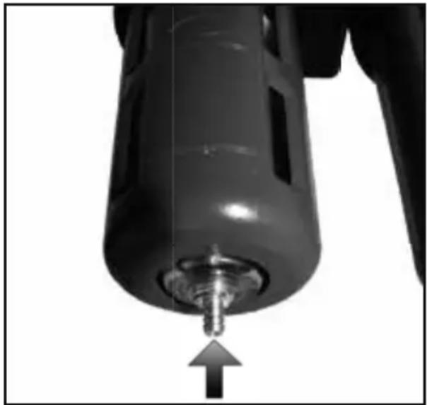
- Drain the pneumatic maintenance unit's tank at regular intervals. For this, press in the metal pin at the bottom and let the condensate drain. Note that the pneumatic maintenance unit must be depressurised for safety.
Troubleshooting
| Faults Causes | Solution | |
| The lubrication is not sufficient | The oil passage screw it tightened too far in direction ("−"). | Increase lubrication (see above). |
| The compressed air volume is too low, i.e. below the minimum fill level. | Pour more oil into the oil tank. Observe the maximum fill level. | |
| The operating pressure of the compressed air is too low. | The pressure controller is tightened too far (see above). | Increase the pressure (see above). |
Cleaning and maintenance

Note:
The pneumatic maintenance unit must be regularly serviced and overhauled for
proper function and for compliance with the safety requirements. Improper and wrong operation may cause failures and damage to the device.
Warranty and service information
Warranty from Creative Marketing Consulting GmbH
Dear Customer,
The warranty for this device is 3 years from the date of purchase. In the event of product defects, you have legal rights against the retailer of this product. Your statutory rights are not affected in any way by our warranty conditions, which are described below.
- Warranty conditions
The warranty period begins on the date of purchase. Please retain the original sales receipt. This document is required as your proof of purchase. Should this product show any defect in materials or manufacture within 3 years from the date of purchase, we will repair or replace it – at our discretion – free of charge. To claim against this warranty, you must present the defective device and your purchase receipt within the 3-year period, and include a brief written description of the nature of the defect and the date it occurred. If the defect is covered by our warranty, we will repair and
- Never use any sharp and/or scraping cleaning return your product or send you a replacement.
agents or solvents. They may damage the plastic parts of the pneumatic maintenance unit.
The original warranty period is not extended when a device is repair or replaced.
■ Make sure that no water can enter inside the oiler.
- Ensure that the housing and the inside of the pneumatic maintenance unit remains dust- and dirt-free. For this, regularly rub the pneumatic maintenance unit with a clean cloth.
- Extent of warranty
The device has been manufactured according to strict quality guidelines and meticulously examined
before delivery. The warranty applies to material and manufacturing defects only. This warranty does not extend to product parts which are subject to normal wear and tear and can thus be regarded as consumable parts, or for damages to fragile parts, e.g. switches, rechargeable batteries, or parts made from glass. This warranty is voided if the product becomes damaged or is improperly used or maintained. For proper use of the product, all of the instructions given in the operating instructions must be followed precisely. If the operating instructions advise you or warn you against certain uses or actions, these must be avoided in all circumstances. The product is for consumer use only and is not intended for commercial or trade use. The warranty becomes void in the event of misuse and improper use, use of force, and any work on the device that has not been carried out by our authorised service branch.
- Processing of warranty claims
Please follow the instructions below to ensure quick processing of your claim: Please retain your proof of purchase and quote the product number (e.g. the IAN 12345) in all correspondence. The product number can be found on the type plate, an engraving, the cover page of your instructions (bottom left), or the sticker on the back or bottom. In the event of malfunctions or other defects, please first contact our service department below by phone or email. If your product is found to be defective, you can then send your product with proof of purchase (till receipt) and a statement describing what the fault involves and when it occurred free of charge to the service address given.

Note
If you visit www.lidl-service.com, you can download this manual and many other manuals, product videos and software.
Service
How to contact us:
GB, IE, NI
Name: C. M. C. GmbH
Website: www.cmc-creative.de
E-mail: service.gb@cmc-creative.de
Phone: 0-808-189-0652
Registered office: Germany
IAN 292166
Please note that the following address is not a service address. Please first contact the service point given above.
Address:
C. M. C. GmbH
Katharina-Loth-Str. 15
D-66386 St. Ingbert
GERMANY
Environmental notes and disposal information

Always recycle the device, accessories and packaging in an environmentally-friendly manner.
Do not dispose of pneumatic devices in household waste! Devices that are no longer functional should be recycled wherever possible. Ask your local stockist for advice.
- Disposal of the maintenance unit
Dispose of the maintenance unit according to the provisions applicable in your country. If the maintenance unit can no longer be used, return it to a collection point of your municipality/quarter. This ensures that it will be professionally recycled and avoids negative effects on the environment.
Table of contents
Symbolforklaring .... Side 16
Indledning....Side 16
natural_image
Close-up of a black mechanical device with multiple ports and a small bottle, no visible text or symbols.natural_image
Close-up of a mechanical component with a cylindrical shaft inserted, showing internal structure and an arrow indicating direction (no text or symbols)Ibrugtagning
Forbind trykluft-serviceenheden med trykluftkilden

natural_image
Close-up of a mechanical component with curved arrows indicating rotational motion (no text or symbols)natural_image
Close-up of a mechanical component with a pointed tip and arrow indicator (no text or symbols)- Olietågeenhed
natural_image
Close-up of a mechanical component with black housing and attached clamps (no visible text or symbols)natural_image
Close-up of a mechanical device with a cylindrical component inserted, showing internal structure and an arrow indicating motion (no text or symbols visible)Inbetriebnahme
natural_image
Close-up of a mechanical component with curved arrows indicating rotational motion (no text or symbols)natural_image
Close-up of a mechanical component with a metallic screw and an arrow pointing to it (no visible text or symbols)- Ölneblereinheit
service.at@cmc-creative.de
service.ch@cmc-creative.de
Telefon: +49 (0) 6894 9989751
- AIR FILTER REGULATOR AND LUBRICATOR PDWE 8 A1
- AIR FILTER REGULATOR AND LUBRICATOR
- TRYKLUFT-SERVICEENHED
- DK
- Safety notes for using pneumatic devices....Seite 8
- Before starting up....Seite 9
- Installation ......Seite 10
- Starting up......Seite 10
- Cleaning and maintenance......Seite 12
- Warranty and service information......Seite 12
- Environmental notes and disposal information....Seite 13
- Air-driven maintenance unit PDSP 8 A1
- Introduction
- KEEP OUT OF THE REACH OF CHILDREN!
- - Intendeduse
- - Residual risk
- - Parts description
- • Technical specifications
- - Package contents
- Safety notes
- Safety notes for using pneumatic devices
- Important!
- User safety
- Forbidden uses
- Important note:
- Before starting up
- Installation
- Attention:
- • Filling the oil mist unit
- Starting up
- Connect the pneumatic maintenance unit to the compressed air source
- - Setting the working pressure
- Note:
- - Filter unit
- - Condensate drain via the drain valve
- - Oil mister unit
- Cleaning and maintenance
- Warranty and service information
- Warranty from Creative Marketing Consulting GmbH
- - Warranty conditions
- - Extent of warranty
- - Processing of warranty claims
- Note
- Service
- How to contact us:
- IAN 292166
- Address:
- Environmental notes and disposal information
- - Disposal of the maintenance unit
- Symbolforklaring .... Side 16
- Indledning....Side 16
- Ibrugtagning
- Forbind trykluft-serviceenheden med trykluftkilden
- - Olietågeenhed
- Inbetriebnahme
- - Ölneblereinheit
Brand : PARKSIDE
Model : PDWE 8 A1
Category : Industrial air filter