ZIPS360NNSS - Refrigerator Monogram - Free user manual and instructions
Find the device manual for free ZIPS360NNSS Monogram in PDF.


| Product Type | Two-door built-in refrigerator with bottom freezer |
| Brand | Monogram |
| Model | ZIPS360NNSS |
| Width | 36 in (91.44 cm) |
| Recommended Opening Height | 83 1/2 in to 84 1/2 in (212.1 to 214.6 cm) |
| Opening Depth | 24 in (60.96 cm) |
| Weight (fully loaded) | Approximately 544 kg (1200 lb) |
| Power Supply | 115 V, 60 Hz, 15 or 20 A, dedicated grounded circuit |
| Water Supply | Cold potable water, 40-120 psi (275-827 kPa) |
| Ice Maker | Automatic with feeler arm, ON/OFF switch |
| Auto Fill | Auto fill pitcher |
| Temperature Settings | Refrigerator 37 °F (2.8 °C), freezer 0 °F (-17.8 °C) |
| Door Stop | 3 positions: 90°, 115°, 130° |
| Leveling | Front leveling feet, rear adjustable rollers, max height 1 in |
| Anti-Tipping Device | Wall bracket with L-rod and cotter pin or cabinet attachment |
| Decorative Panels | Overlay or framed panels (custom) |
| Maximum Panel Weight | Refrigerator door 30 lb (14 kg), freezer drawer 28 lb (13 kg), grille 11 lb (5 kg) |
| Water Filter | Bypass plug for reverse osmosis, integrated filter cartridge |
| Maintenance | Clean grilles, check seals, replace filter per instructions |
| Warranty | See user manual for terms |
| Customer Service | monogram.com or monogram.ca for Canada |
| Replacement Parts | Available at monogram.com/use-and-care/parts |
Frequently Asked Questions - ZIPS360NNSS Monogram
User questions about ZIPS360NNSS Monogram
0 question about this device. Answer the ones you know or ask your own.
Ask a new question about this device
Download the instructions for your Refrigerator in PDF format for free! Find your manual ZIPS360NNSS - Monogram and take your electronic device back in hand. On this page are published all the documents necessary for the use of your device. ZIPS360NNSS by Monogram.
USER MANUAL ZIPS360NNSS Monogram
36" Built-In French Door,
Bottom-Freezer Refrigerators
Read these instructions completely and carefully.
- IMPORTANT – Save these instructions for local inspector's use. Observe all governing codes and ordinances.
- Note to Installer – Be sure to leave these instructions with the Consumer.
- Note to Consumer – Keep these instructions with your Owner's Manual for future reference.
If you received a damaged unit, you should immediately contact your dealer or builder.
Skill Level – Installation of this unit requires basic mechanical, carpentry and plumbing skills. Proper installation is the responsibility of the installer. Product failure due to improper installation is not covered under the Monogram Warranty. See the Owner's Manual for warranty information.
WARNING

Electrical Shock Hazard.
Plug into a grounded 3-prong outlet.
Do not remove the ground prong.
Do not use an adapter.
Immediately discontinue use of a damaged supply cord. If the supply cord is damaged it must be replaced by a qualified service professional with an authorized service part from the manufacturer.
Do not use an extension cord with this appliance.
Failure to follow these instructions can result in death, fire, or electrical shock.
Follow the instructions in the section Grounding the unit.
This appliance must be installed with a means in the fixed house wiring or circuit breaker for disconnecting the appliance from the electrical supply after installation.
WARNING

ver Hazard.
These appliances are top heavy, especially with any doors open, and must be secured to prevent tipping forward which could result in death or serious injury. Read and follow the entire installation instructions for securing the appliance with the anti-tip system.
WARNING

or Explosion Hazard.
Keep flammable materials and vapors away from appliance. Failure to do so can result in fire, explosion, or death.
WARNING
To reduce the risk associated with choking, do not allow children under 3 years of age to small parts during the installation of this product.
CAUTION
Lifting Hazard
This unit is very heavy. To reduce the risk of person injury during maneuvering and installing this appliance, 3 people are required for proper installation.
CAUTION
Keep fingers out of the "pinch point" areas; clearances between the doors and between the net are necessarily small. Be careful closing doors when children are in the area.
For Monogram local service in your area, visit monogram.com
For Monogram service in Canada, visit monogram.ca
For Monogram Parts and Accessories, visit monogram.com/use-and-care/parts
Instructions for Standard Installation 6
Design Guide
The Installation Space 7
Dimensions and Clearances 7
Custom Handle Design Guide 8
Customization Basics 8
Optional Accessory Kit 8
Refrigerator Location 8
3/4" Overlay Panel Dimensions 9
1/4" Framed Panel Dimensions 10
Side Panels 10
130° Door Swing 11
90° Door Swing 12
Installation Instructions
Tools, Hardware, Materials, Flooring 13
Refrigerator Location 13
Grounding the Unit 13
Step 1. Remove Packaging 14
Step 2. Install Water Line 15
Step 2A. Water Line with Reverse
Osmosis System or other Household
Filtration System 15
Step 3. Install Side Panels 16
Step 4. Anti-Tip Procedures 16
Step 5. Level Refrigerator 18
Step 6, Secure Unit to Wall 18
Step 7. Alternate Anti-Tip Procedure 19
Step 8. Adjust Door Swing 19
Step 9. Install Grille Panel 20
Step 10. Install 1/4" Framed Panels 20
Step 10A. Install Overlay Panels 21
Step 11. Connect Water Supply 22
Step 12. Connect Power 22
Step 13. Start Icemaker 23
Step 14. Install Toekick 23
Inspect Final Installation 23
Instructions for Flush Inset Installation 24
Instructions for Stainless Steel Installation 25
Design Guide
The Installation Space 26
Dimensions and Clearances 26
Customization Basics 27
Side Panels 27
Refrigerator Location 27
130° Door Swing 28
90° Door Swing 29
Installation Instructions
Tools, Hardware, Materials, Flooring 30
Grounding the Refrigerator 30
Step 1. Remove Packaging 31
Step 2. Install Water Line 32
Step 2A. Water Line with Reverse
Osmosis System or other Household
Filtration System 33
Step 3. Install Side Panels 33
Step 4. Anti-Tip Procedure 33
Step 5. Level Refrigerator 35
Step 6. Secure Unit to Wall 35
Step 7. Alternate Anti-Tip Procedure 36
Step 8. Adjust Door Swing 36
Step 9. Connect Water Supply 37
Step 10. Connect Power 38
Step 11. Start Icemaker 38
Step 12. Install Toekick 39
Inspect Final Installation 39
Instructions for Standard Installation
THE INSTALLATION SPACE
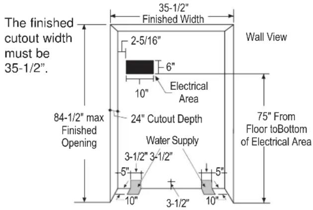
Water And Electrical Locations
Electrical and water supply must be located as shown.
The cutout depth must be 24" (60.96 cm)
The refrigerator will project forward, slightly beyond adjacent cabinetry, depending on your installation. Allow minimum 1/8" (0.32 cm) air gap between case back & wall.
Cutout depth beneath a soffit:
When installed beneath a soffit, the soffit cannot exceed the 24" (60.96 cm) installation depth shown. The top case trim overlaps the bottom of the soffit.
Additional Specifications
- A 115 volt 60Hz., 15 or 20 amp power supply is required. An individual properly grounded branch circuit or circuit breaker is recommended. Install a properly grounded 3-prong electrical receptacle recessed into the back wall. Electrical must be located on rear wall as shown.
- Water line can enter the opening through the floor or back wall. Route SmartConnect™ kit or 1/4" O.D. copper tubing between the cold water line and the water connection location. The tubing should be long enough to extend to the front of the refrigerator. Installation of an easily accessible shut-off valve in the water line is required.
DIMENSIONS AND CLEARANCES
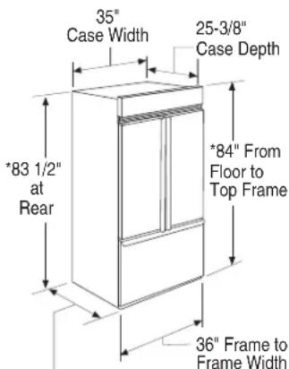
Depth Including
3/4" Panel - Handles: 25-15/16"
* Shipping height. The refrigerator can be adjusted to fit into a cutout that is 83-1/2" (212 cm) min. to 84-1/2" (214.63 cm) max. height. Note that the top case trim at the front is 1/2" (1.27 cm) higher and will overlap upper cabinetry or soffit. Use leveling legs and wheels for a maximum 1" (2.54 cm) height adjustment.
Product Clearances
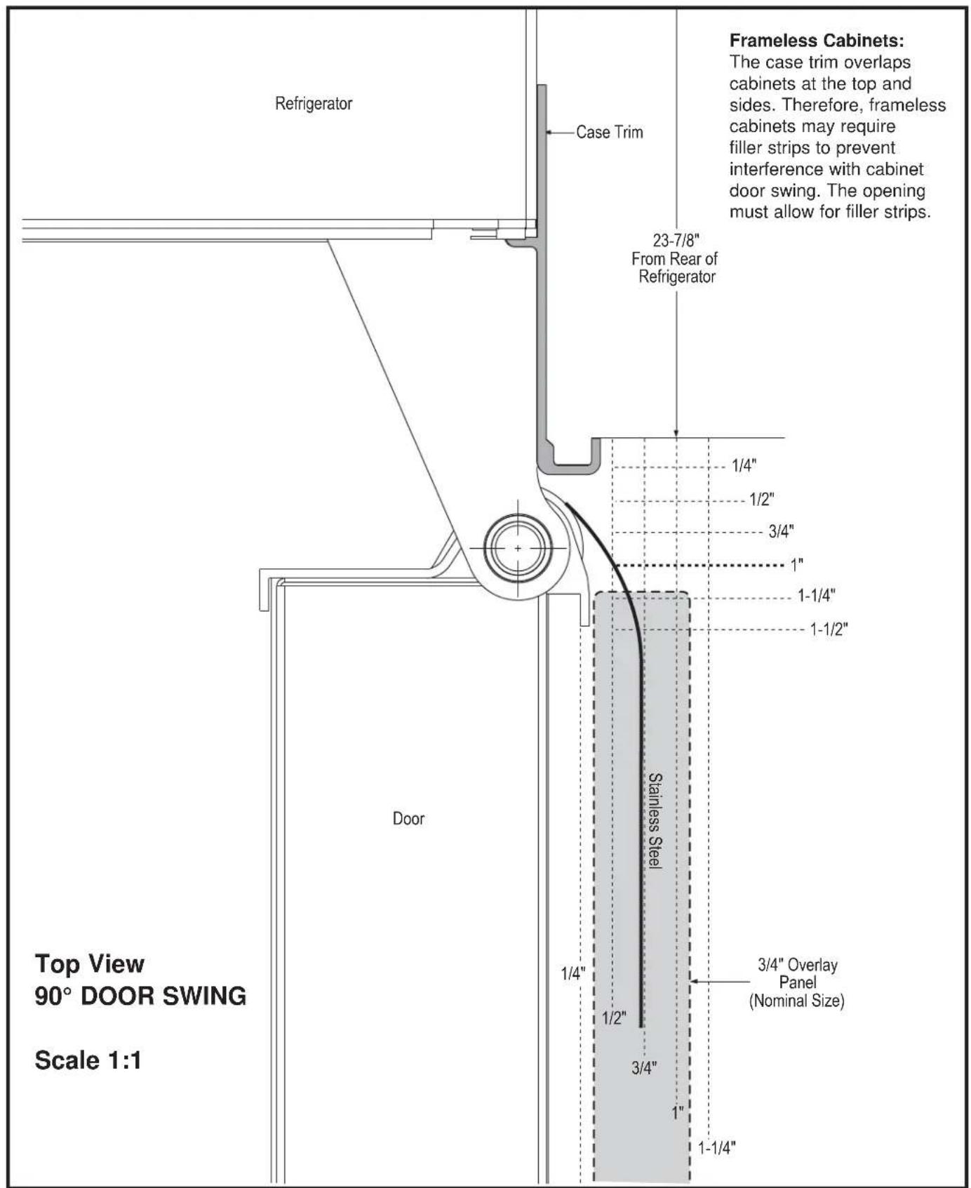
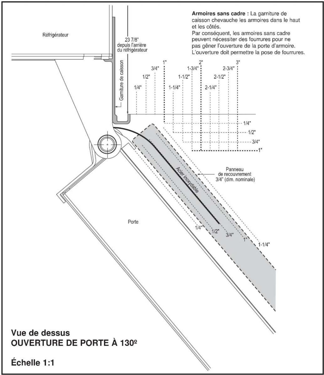
These refrigerators are equipped with a 3-position door stop. The factory set 115° door swing can be adjusted to 90° if clearance to adjacent cabinets or walls is restricted.
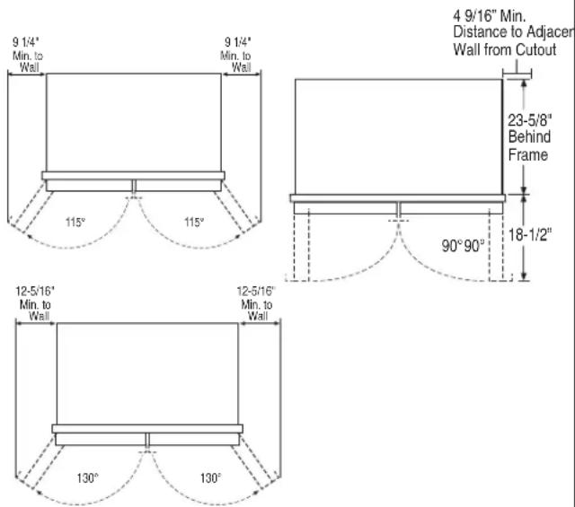
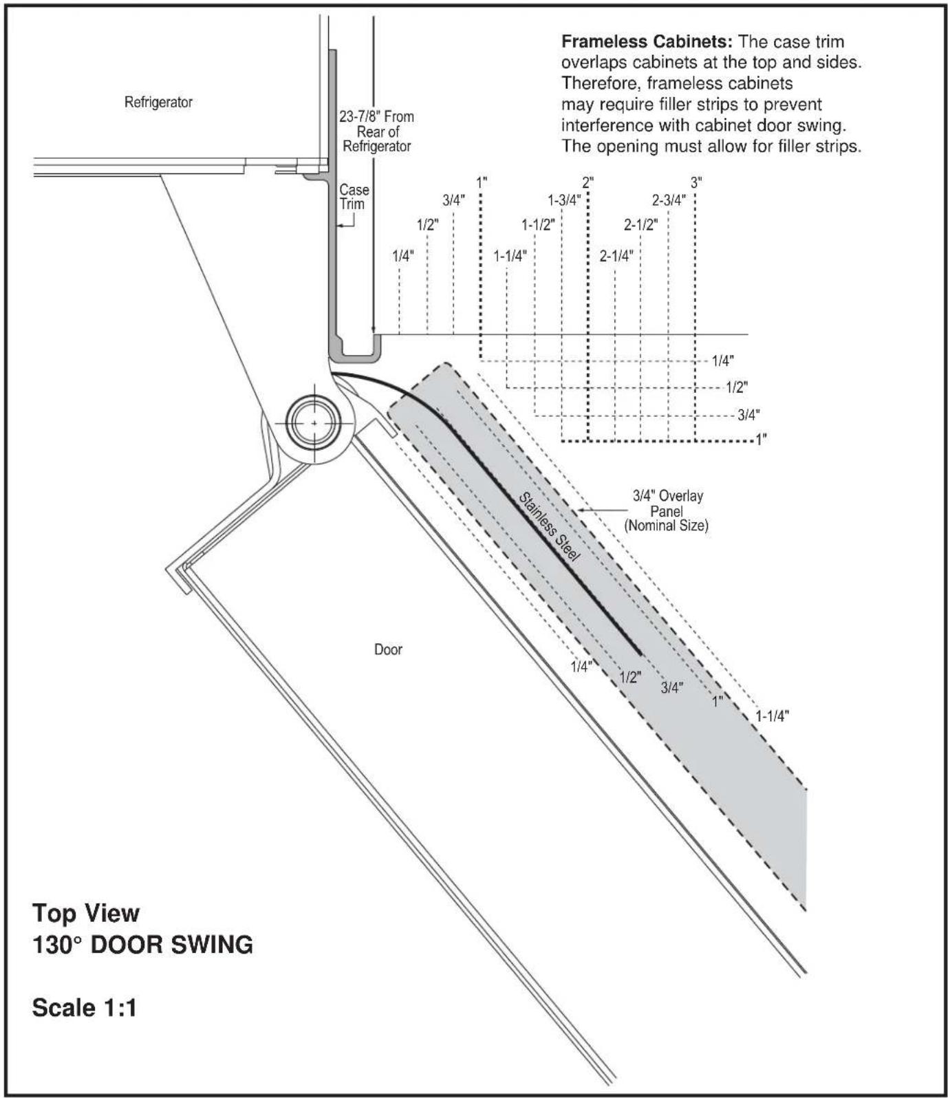
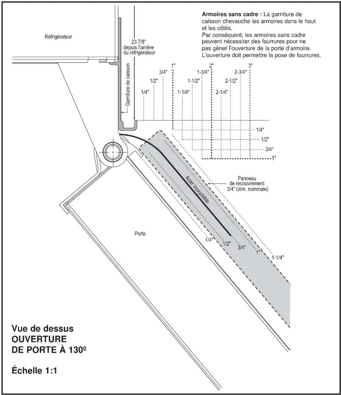
Allow 12-5/16" (31.27 cm) minimum clearance for a full 130° door swing.
For a 90° door swing, allow 4 9/16" (11.59 cm) min. clearance to adjacent wall from cutout. If the 90° door stop position is used, pan access is maintained, but pan removal is restricted.
See illustrations pages 11 and 12 to determine door swing interaction with adjacent cabinets or countertops.
CUSTOM HANDLE DESIGN GUIDE
Custom handles must be used for flush installation. For custom handle installation, counterbore holes in rear of decorative panels must ensure 1/2" (1.27 cm) material thickness remains for handle support.
NOTE: The counterbore must not exceed 1" (2.54 cm) in diameter.
Minimum distance on Fresh Food Doors from handle side edge to handle center should be 1-1/4" (3.18 cm) on each door as shown.
Minimum distance on Freezer Door from top edge to handle center on the freezer drawer should be 1-1/4" (3.18 cm) as shown.
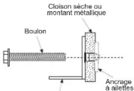
Countersink screw into panel as shown.
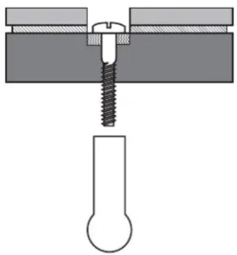
natural_image
Mechanical assembly diagram showing a screw inserted into a plate, with a separate view of a bulb (no text or symbols present)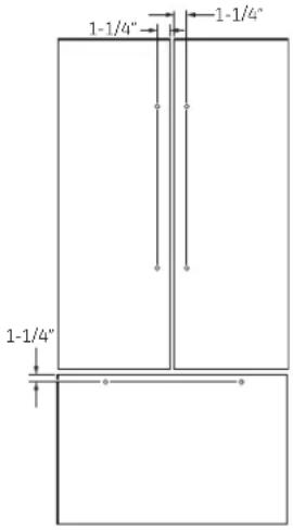
CUSTOMIZATION BASICS:
Framed Or Overlay Panels, Custom Handles and Accessory Kits
These refrigerators are designed to be customized with decorative panels. Field installed custom door and grille panels are required.
Side Panels
Side panels must be used whenever the sides of the refrigerator will be exposed.
REFRIGERATOR LOCATION
- Do not install the refrigerator where the temperature will go below 60^ F ( 16^ C). It will not run often enough to maintain proper temperatures.
- Do not install the refrigerator where temperatures will go above 100°F (37°C). It will not perform properly.
- Do not install the refrigerator in a location exposed to water (rain, etc.) or direct sunlight.
- Install it on a floor strong enough to support it fully loaded.
OPTIONAL ACCESSORY KITS
ZKLN: Visor handle kit for use on custom panel models in a standard installation.
3/4" (1.91 cm) OVERLAY PANEL DIMENSIONS
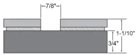
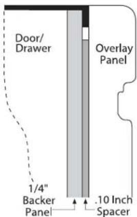
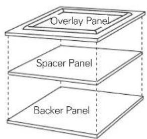
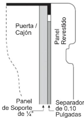
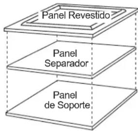
For a more custom appearance, overlay panels may be installed on trimmed models. The overlay panel must be secured to a 1/4" (0.64 cm) thick backer panel which slides into the trim. A spacer panel 0.10" (0.25 cm) thick must be placed between the overlay and backer panel.
Assemble the panels with glue and screws.
- Center the spacer panel on the backer panel, left to right and top to bottom. Secure the panels with glue.
- Refer to the following chart for locating the backer panel to the overlay panel. Secure the overlay panel to the backer panel with glue and screws. Screws must be countersunk into the backer panel.
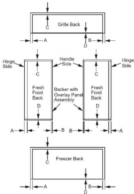
flowchart
graph TD
    A["Grille Back"] --> B["Handle Side"]
    B --> C["Backer with Overlay Panel Assembly"]
    C --> D["Freezer Back"]
    subgraph Grille Back
        A1["A"] --> C1["C"]
        C1 --> D1["D"]
        D1 --> E["Hinge Side"]
    end
    subgraph Fresh Food Back
        C2["C"] --> D2["D"]
        D2 --> E
        E --> F["Hinge Side"]
    end
    subgraph Freezer Back
        C3["C"] --> D3["D"]
        D3 --> E
        E --> F
    end
.25" + .10" + .75" = 1.10" Total Panel Thickness (0.64 + 0.25 + 1.9 = 2.79 cm)
NOTE: Left-to-right offset is not always equal to top-to-bottom offset.
Panel Locations
| A | B | C | D | |
| Door Panels 1/8" (0.32 cm) | 0 1/8" (0.32 cm) | 1/8" (0.32 cm) | ||
| Drawer Panel 1/8" (0.32 cm) | 1/8" (0.32 cm) | 1/16" (0.16 cm) | 1/16" (0.16 cm) | |
| Grille Panel 1/8" (0.32 cm) | 1/8" (0.32 cm) | 1/16" (0.16 cm) | 1/16" (0.16 cm) | |
Panel Dimensions
| Fresh Food Freezer Grille | |||
| 1/4" (0.63 cm) Backer Panel | 46-1/16" x 16-1/2" (116.99 x 14.91 cm) | 33-7/8" x 21-7/8" (86.04 x 55.56 cm) | 33-7/8" x 8-7/8" (86.04 x 22.54 cm) |
| 0.10" (0.25 cm) Spacer Panel | 44-11/16" x 15" (113.51 x 38.10 cm) | 32-1/2" x 20-1/2" (82.55 x 52.07 cm) | 32-1/2" x 7-5/8" (82.55 x 19.37 cm) |
| 3/4" (1.9 cm) Overlay Panel | 46-5/16" x 16-5/8" (117.63 x 42.23 cm) | 34-1/8" x 22" (96.67 x 55.88 cm) | 34-1/8" x 9" (96.67 x 22.86 cm) |
IMPORTANT NOTE: Maximum total weight for the assembled panels:
- Fresh food door panels – 30 lbs. (14 kg)
- Freezer drawer panel – 28 lbs. (13 kg)
- Grille Panel – 11 lbs. (5 kg)
1/4" (0.63 cm) FRAMED PANEL DIMENSIONS
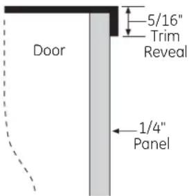
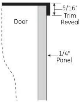
If you choose to install framed panels, they must be cut to the dimensions shown. The panels will slide into the frame on the door, drawer and grille.
If the custom panel is less than 1/4" thick and if it fits loosely in the door frame, it can be backed up with a piece of filler material or foam tape to improve the fit.
Panel Dimensions
| 1/4" (0.63 cm) Framed Panel | 46-1/16" x 16-1/2" (101.76 x 41.91 cm) | 33-7/8" x 21-7/8" (86.04 x 55.56 cm) | 33-7/8" x 8-7/8" (86.04 x 22.54 cm) |
NOTE: Maximum total panel weight:
- Fresh food door panel – 58 lbs. (26 kg)
• Freezer drawer panel – 28 lbs. (13 kg)
• Grille Panel – 11 lbs. (5 kg)
SIDE PANELS
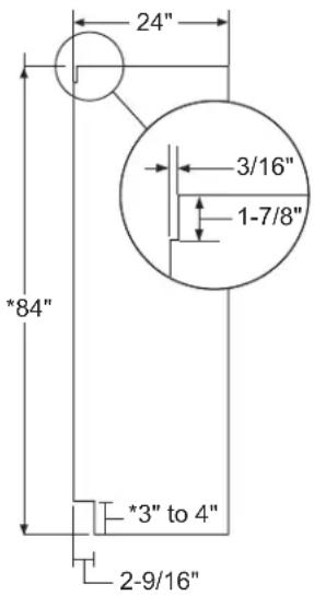
Side panels must be used whenever the sides of the refrigerator will be exposed. The 1/4" (0.63 cm) side panels will slip into the side case trim. Secure the panels to the refrigerator with stick-on hook and loop fastener strips. Order the side panels from the cabinet manufacturer.
- Cut a notch in the top front corner as shown to allow clearance for corner keys in the front side trim.
* Depending on installation height.
Design Guide - Standard Installation
Design Guide - Standard Installation
Installation Instructions - Standard Installation
TOOLS REQUIRED
- Tinsnips to cut banding • Stepladder
- Bucket • Level
- Appliance Hand Truck • Tubing cutter
- 7/16" open-end wrench • #2 Phillips screwdriver
- Drill and appropriate bits • 5/16", 7/16" socket
- Safety glasses • 1-1/4" open end wrench
- Pliers • 1/4" ratchet
MATERIALS REQUIRED
- 35" long 2x4 for Anti-Tip support
- 1/4" copper water line tubing or SmartConnect™ Refrigerator Tubing kits
• Water shut-off valve - Custom panels for fresh food door, freezer drawer and grille panel
- Screws to secure refrigerator to cabinetry.
- Stick-on hook and loop fastener strips for 1/4" (0.63 cm) side panels
HARDWARE SUPPLIED
• Water filter bypass plug
- Anti-Tip brackets
- 1/4" nut and ferrule
FLOORING
For proper installation, this refrigerator must be placed on a level surface of hard material that is at the same height as the rest of the flooring. This surface should be strong enough to support a fully loaded refrigerator, or approximately 1,200 lbs. (544.31 kg).
NOTE: Protect the finish of the flooring. Cut a large section of the cardboard carton and place under the refrigerator where you are working.
REFRIGERATOR LOCATION
- Do not install the refrigerator where the temperature will go below 60^ F ( 16^ C). It will not run often enough to maintain proper temperatures.
- Do not install the refrigerator where temperatures will go above 100^ (37°C). It will not perform properly.
- Do not install the refrigerator in a location exposed to water (rain, etc.) or direct sunlight.
- Install it on a floor strong enough to support it fully loaded.
GROUNDING THE REFRIGERATOR
⚠ WARNING

Electrical Shock Hazard.
Failure to follow these instructions can result in death, fire, or electrical shock.
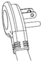
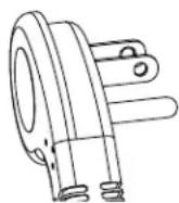
The power cord of this appliance is equipped with a 3-prong (grounding) plug which mates with a standard 3-prong (grounding) wall receptacle to minimize the possibility of electric shock hazard from this appliance.
Have the wall outlet and circuit checked by a qualified electrician to make sure the outlet is properly grounded.
Where a standard 2-prong wall outlet is encountered, it is your personal responsibility and obligation to have it replaced with a properly grounded 3-prong wall outlet.
DO NOT, UNDER ANY CIRCUMSTANCES, CUT OR REMOVE THE THIRD (GROUND) PRONG FROM THE POWER CORD.
DO NOT USE AN ADAPTER PLUG TO CONNECT THE REFRIGERATOR TO A 2-PRONG OUTLET.
DO NOT USE AN EXTENSION CORD WITH THIS APPLIANCE.
MISE À LA TERRE DU RÉFRIGÉRATEUR
▲AVERTISSEMENT

Risque de choc
électrique.
- Carefully cut banding at the top and bottom, remove the outer carton.
- Slide out the back corner posts (2).
- Slide the carton off the top of the cabinet.
NOTE: IT IS NOT NECESSARY TO LAY THE CABINET DOWN IN ORDER TO REMOVE THE SKID!
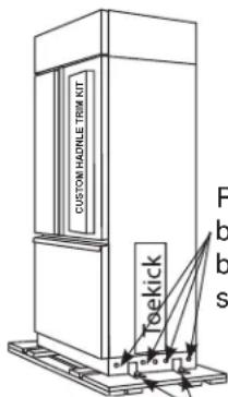
Remove 2 strap bolts on each side
- The unit is secured to the skid with 2 full-length tie-down straps. Remove the ten 5/16" bolts from the base channels in the tie-downs.
- Remove the four 7/16" bolts securing the straps to the skid.
NOTE: DO NOT ATTEMPT TO ROLL UNIT OFF SKID.
- The support blocks on the bottom of the refrigeration case must be removed before the refrigerator is taken off the skid or damage will occur. Carefully tilt the refrigerator and slide the blocks out from beneath.
- Remove the toekick and set aside for final installation.
- Lift the refrigerator off the skid with an appliance dolly. Handle from the sides.
STEP 1 REMOVE PACKAGING
WARNING

ver Hazard.
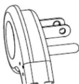
Refrigerator is much heavier at the top than at the bottom. To avoid a risk of death or serious injury, be careful when moving, and when using a hand truck, handle only from side.
DO NOT ATTEMPT TO ROLL UNIT OFF SKID.
AVERTISSEMENT

de basculement
Connect to potable water supply only.
A cold water supply is required for automatic icemaker operation. The water pressure must be between 40 and 120 psi (275-827 kilopascals).
WARNING

.ECTRIC SHOCK HAZARD
Attach tubing clamp using existing hole only. DO NOT drill into the refrigerator.
AVERTISSEMENT
- A cold water supply is required for automatic icemaker operation. The water pressure must be between 40 and 120 p.s.i. (275-827 kPa).
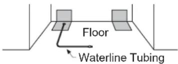
- Route 1/4" OD copper or SmartConnect™ plastic tubing between house cold water line and the water connection location.
- Tubing should be long enough to extend to the front of the refrigerator. Allow enough tubing to accommodate bend leading into the water line connection.
STEP 2 INSTALL WATER LINE
(Cont.)
NOTE: The only Monogram-approved plastic tubing is supplied in the SmartConnect™ Refrigerator Tubing kits. Do not use any other plastic water supply line because the line is under pressure at all times. Other types of plastic may crack or rupture with age and cause water damage to your home.
SmartConnect™ Refrigerator Tubing Kits are available in the following lengths:
2' (.6 m) - WX08X10002 8' (2.4 m) - WX08X10006
15' (4.6 m) - WX08X1 0015 25' (7.6 m) - WX08X10025
Shut off the main water supply.
Turn on the nearest faucet long enough to clear the line of water.
- Install a shut-off valve between the icemaker water valve and cold water pipe in a basement or cabinet. The shut-off valve should be located where it will be easily accessible.
- Turn on the main water supply and flush debris. Run about a quart of water through the tubing into a bucket. Shut off water supply at the shut-off valve.
NOTE: Saddle type shut-off valves are included in many water supply kits, but are not recommended for this application.
NOTE: Commonwealth of Massachusetts Plumbing Codes 248CMR shall be adhered to. Saddle valves are illegal and use is not permitted in Massachusetts. Consult with your licensed plumber.
STEP 2A WATER LINE INSTALLATION WITH A REVERSE OSMOSIS SYSTEM OR OTHER HOUSEHOLD FILTRATION SYSTEM
Skip this step when not using an RO System or other household filtration system.
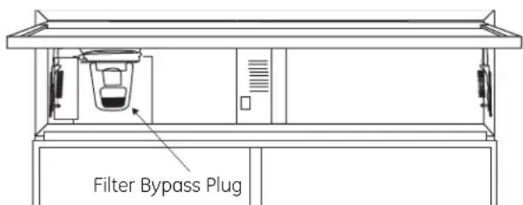
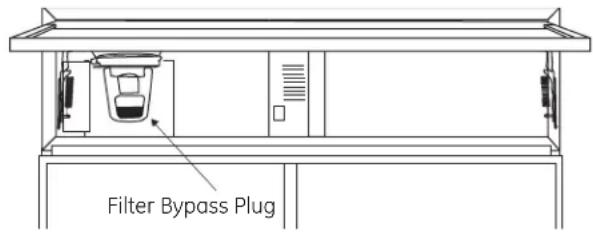
If the water supply to the refrigerator is from a household filtration system, use the refrigerator's filter bypass plug. Using the refrigerator's water filtration cartridge with the RO filter can result in hollow ice cubes.
STEP 3 INSTALL SIDE PANELS
Skip this step when not using side panels.
If you are using 1/4" (0.63 cm) side panels, they should be inserted into the case trim. Fasten the panels to the refrigerator with stick-on hook and loop fastener strips before setting refrigerator in place.
STEP 4 ANTI-TIP PROCEDURE
⚠ WARNING

er Hazard.
These refrigerators are top heavy, especially with any doors open, and must be secured to prevent tipping forward which could result in death or serious injury. Read and follow the entire installation instructions for securing the refrigerator with the anti-tip system.
AVERTISSEMENT

- The kit supplied with the unit contains 2 lag bolts and 4 toggles with bolts. The wall bracket will be attached to the wall in 4 places.
- Measure the opening where the unit is to be installed. Mark the center with a vertical line.
- Measure up 81 1/2" (207.01 cm) from the floor. Mark this point on the wall.
STEP 4 ANTI-TIP PROCEDURE (CONT)
- Using a level, draw a horizontal line on the wall at this height.
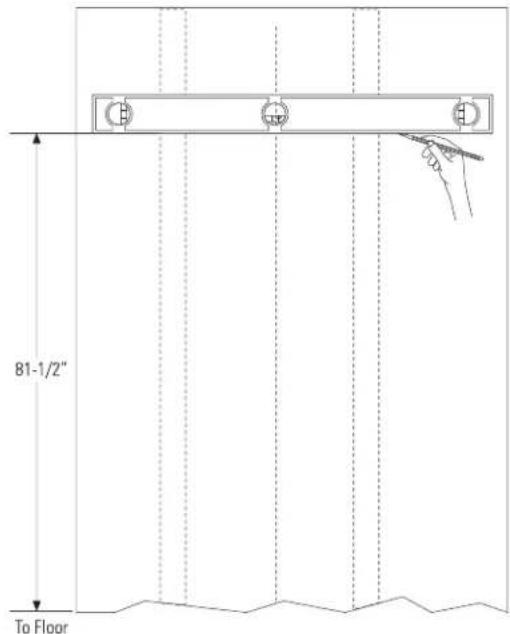
- Locate at least 2 studs on the back wall. Mark these points on the horizontal line.
- Place the bottom of the wall bracket with tabs on the horizontal line. Align the center notch on the bracket with the center line on the wall.
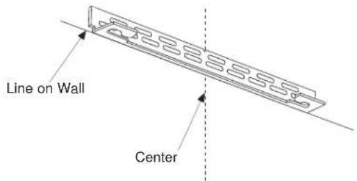
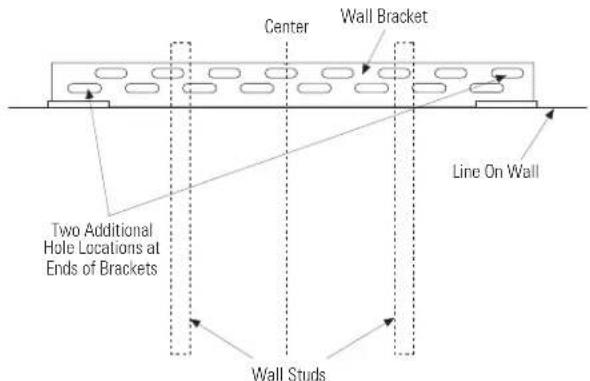
- The anti-tip wall bracket has a series of holes. Select 2 holes that match with the located studs. Make sure the holes selected are on the center of the studs. Mark the wall at these points.
- Mark an additional hole at each end of the bracket. If one of the studs is closer to the end of the bracket, mark an additional hole towards the center of the bracket.
- Drill 1/2" (1.27 cm) holes into the wall board at the locations marked for the toggles to be mounted (not the stud markings).
- Drill 3/16" (0.47 cm) holes into wooden studs where marked. If steel stud construction, drill 1/2" (1.27 cm) holes into the studs where marked. You will use 2 toggles with the metal studs.
Install Wall Toggles:
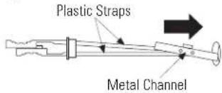
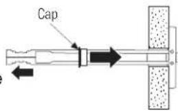
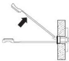
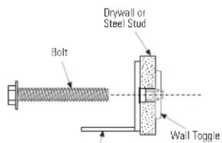
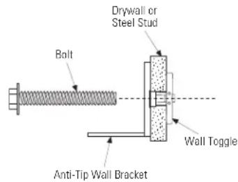
The wall toggles and bolts can be ordered as Service Kit #WR49X10193. Wall toggles are installed in the drywall and metal studs for stability. Install the wall toggles as follows:
- Drill 1/2" (1.27 cm) holes at the wall markings made in the holes at the ends of the wall bracket.
- Hold the metal channel flat against the plastic straps and slide the channel through the hole.
• Gently pull back at the ends of the plastic straps to make the channel rest flush behind the wall. - Hold the ends of the straps in one hand and slide the plastic cap along the straps until the flange of the cap is flush with the wall.
- Place your thumb between the plastic straps and bend up and down to snap the straps off at the wall.
natural_image
Mechanical lever diagram showing pivot point and pivot connection (no text or symbols)STEP 4 ANTI-TIP PROCEDURE (CONT)
Install Screws and Bolts:
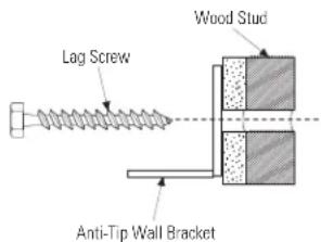
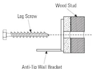
- Have someone hold the wall bracket centered in place with each of the holes aligned with the correct opening in the bracket and level with the horizontal line.
- Insert the lag screws through the bracket and into the stud. Tighten with a wrench.
- Insert the bolts into the toggle by hand until snug. Tighten with a wrench.
Anti-Tip Wall Bracket
CONNECT POWER CORD:
- Before pushing the refrigerator into the opening, plug the power cord into the receptacle. Open the grille panel and reach into the opening at the back to grasp the power cord. Pull the power cord into the opening as you push the refrigerator back.
- Gently push refrigerator into the opening with hands against front corners.
IMPORTANT: When the refrigerator is installed under a soffit or if there is not enough height for this method of security, brackets cannot be used. Proceed to step 5 to level the refrigerator and then to step 7 to secure refrigerator to cabinets.
STEP 5 LEVEL REFRIGERATOR
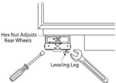
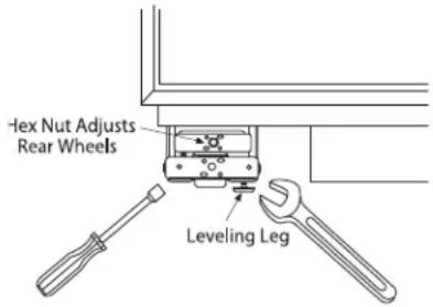
All models have 4-point leveling. The front is supported by leveling legs, the rear is supported by adjustable wheels. Both are accessible from the front of the refrigerator.
- To level the back of the refrigerator, turn the 7/16" hex nut located above the front wheels. Turn clockwise to raise or counterclockwise to lower the refrigerator.
- For front leveling, use a 1-1/4" open-end wrench.
- Adjust height of refrigerator to match installation
cutout opening
83-1/2" (212.09
cm) to 84-1/2"
(214.63 cm). The
refrigerator should be level and plumb with cabinetry.
STEP 5 LEVEL REFRIGERATOR (Cont.)
The rear leveling wheels and front leveling legs are limited to a maximum height adjustment of 1" (2.54 cm). If the installation requires more than 84-1/2" (214.63 cm) height, the installer should elevate the refrigerator on a sheet of plywood or runners. Cabinetry trim could also be added across the top of the opening to shorten the opening. If you attempt to raise the refrigerator more than 1" (2.54 cm), you will damage the front leveling legs and the rear leveling wheels.
STEP 6 SECURE UNIT TO WALL
- The "L" rod can be found in the upper left corner of the unit in the access compartment. Look through the access compartment to make sure the rod lines up with the anti-tip bracket.
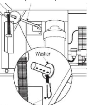
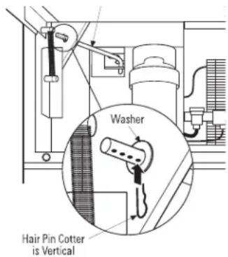
- There are 2 washers and a hair pin cotter with the rod. Remove the washers and hair pin cotter from the end of the rod.
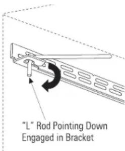
- Rotate and move the "L" rod into the slot in the anti-tip bracket tab. Once it is in the slot, rotate the "L" rod so the hook portion is pointing down. The holes at the front end of the rod should be in a vertical position.
- Pull out on the end of the rod to make sure it is secure in the bracket.
- Locate the hole on the rod that is closest to the unit. A hair pin cotter will be put through this hole to secure the rod. If this hole appears to be too far away for a snug fit against the unit, add the washers one at a time until the pin will fit tightly into the hole.
- Align the straight section of the pin with the hole from the underside of the rod. Push the pin up until it snaps into position. Pliers may be used. NOTE: The hair pin cotter must be vertical when this step is completed
to ensure the "L" rod is engaged in the bracket.
- Check the rod for tightness by pulling forward. If the rod moves, remove the hair pin cotter and place another washer on the rod. Reinsert the pin.
Hair Pin Cotter is Vertical
STEP 7 ALTERNATE ANTI-TIP PROCEDURE
The refrigerator must be secured to prevent tipping. If the anti-tip bracket cannot be used, this alternate procedure may be used to secure the refrigerator against tip-over.
- Raise the grille panel to access case trim.
- Use a 3/16" bit to drill four evenly spaced clearance holes through the metal top case trim.
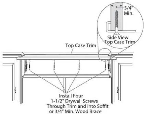
- Use a 1/16" bit to drill to pilot holes through the metal clearance holes and into the wood soffit. The holes should be centered in the soffit or a 3/4" min. wood brace. The brace spanning the enclosure must be securely fastened to cabinets on both sides.
- Install four, 1-1/2" (3.81 cm) drywall screws into the pilot holes.
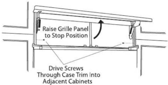
- If no soffit above the unit, drill screws into adjacent cabinets through the side case trim.
STEP 8 ADJUST DOOR SWING
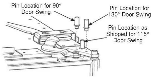
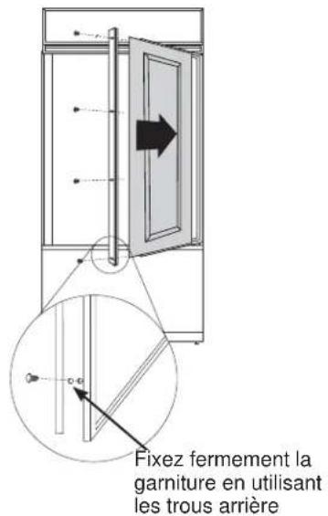
NOTE: This refrigerator has a 3-position door stop. When space does not allow the door to swing open fully to 115°, you may change the door swing to a 90° opening. A 130° door swing is available for standard installation only. If used for flush installation, damage will occur to wood panels. Skip this step if door opening is satisfactory for your installation situation.
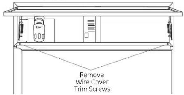
- Lift the grille panel to access the wire cover trim.
- Remove screws on both sides of the wire cover trim and rotate off.
- Use pliers to unscrew door stop and reinstall into the 90^ or 130^ position.
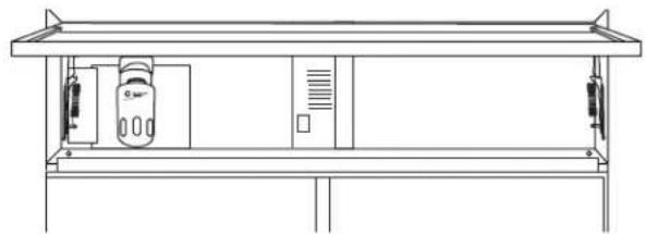
- Reinstall the wire cover trim.
STEP 9 INSTALL GRILLE PANEL
- Raise the access panel to the stop position.
natural_image
Technical line drawing of a mechanical or electrical enclosure unit with no visible text or symbols- Loosen the screws on the side trim behind the frame. Remove the bottom trim.
- Slide the panel over the metal baker panel and into the trim.
- If necessary, tap with a wood block until the panel slips under the top trim piece.
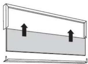
natural_image
Diagram of a mechanical or structural component with two upward arrows indicating direction (no text or symbols)- Reassemble the bottom trim. Tighten the screws.
- Adjust the hinge spring to accommodate the panel weight, if necessary.
STEP 10 INSTALL 1/4" (0.63 cm) FRAMED PANELS
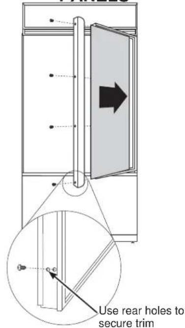
IF YOU ARE INSTALLING OVERLAY PANELS, GO TO STEP 10A.
natural_image
Technical line drawing of a cabinet or storage unit with a downward arrow symbol (no text or labels)Install door and drawer panels:
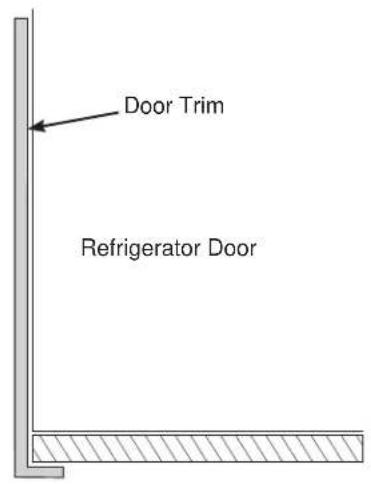
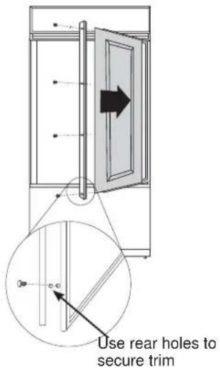
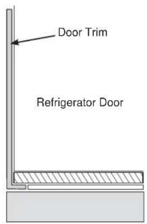
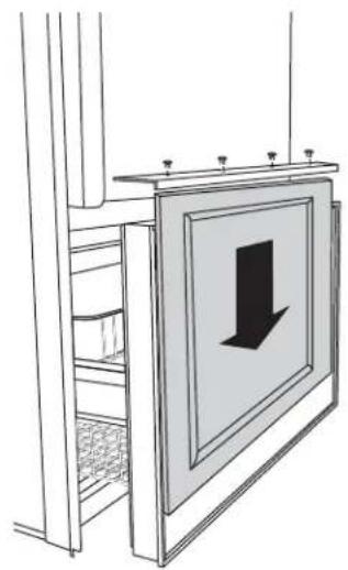
- Open door to 90°. Remove the 8 Phillips head screws from the door trim.
- Remove trim. Retain all screws.
-
Slide framed panel into the door trim.
-
Secure the trim to the door using the screws removed earlier.
- Follow the same procedures to install the second door panel.
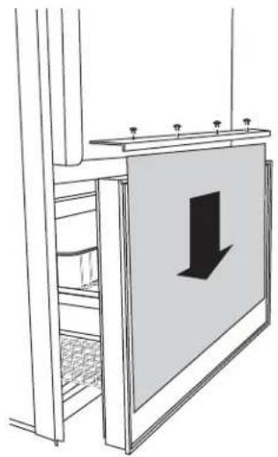
- For freezer drawer, once panel is installed, use all 8 screws holes to install the door trim.
STEP 10A INSTALL OVERLAY PANELS IF YOU ARE INSTALLING FRAMED PANELS, GO TO STEP 10.
natural_image
Technical line drawing of a cabinet or storage unit with a directional arrow symbol (no text or labels)Install door and drawer panels:
- Open door to 90°. Remove the 8 Phillips head screws from the door trim.
- Remove trim. Retain all screws.
- Slide overlay panel into the door trim.
-
Secure the trim to the door using the screws removed earlier.
-
Follow the same procedures to install the second door panel.
- For freezer drawer, once panel is installed, use all 8 screws holes to install the door trim.
STEP 11 CONNECT WATER SUPPLY
WARNING
Connect to potable water supply
only. A cold water supply is required for automatic icemaker operation. The water pressure must be between 40 and 120 psi (275-827 kilopascals).
WARNING

LECTRIC SHOCK HAZARD
Attach tubing clamp using existing hole only. DO NOT drill into the refrigerator.
▲AVERTISSEMENT
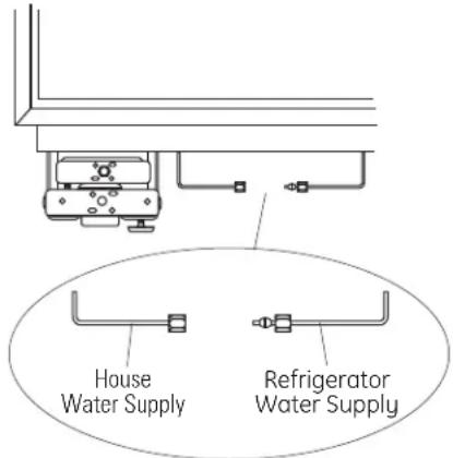
- Locate and bring tubing to the front of the cabinet.
- Turn the water on to flush debris from line. Run about a quart of water through tubing into a bucket, then shut off water.
- Slip a 1/4" nut and ferrule (provided) over both ends of the copper tubing. Insert tube into the union fitting on the unit and tighten nut to union.
- Turn on the water to check for leaks.
Copper Tubing:
STEP 11 CONNECT WATER SUPPLY (Cont.)
SmartConnect™ Tubing:
NOTE: The only Monogram-approved plastic tubing is supplied in the SmartConnect™ Refrigerator Tubing kits. Do not use any other plastic water supply line because the line is under pressure at all times. Other types of plastic may crack or rupture with age and cause water damage to your home.
- Insert the molded end of the tubing into the refrigerator connection. Tighten the compression nut until it is just hand tight.
- Tighten one additional turn with a wrench. Overtightening can cause leaks!
- Turn on the water to check for leaks.
Note: Make sure excess tubing length does not interfere with drawer closing or toekick installation.
STEP 12 CONNECT POWER
- Check to be sure the power cord is plugged into the receptacle.
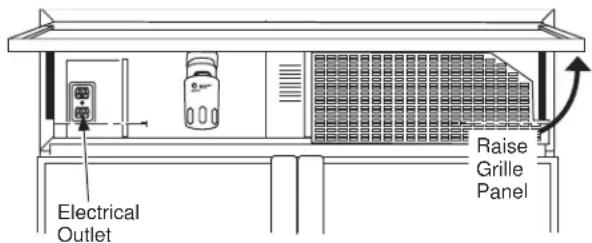
- Check to make sure power to refrigerator is on by opening refrigerator door to see if interior lights are on.
- The temperature controls are preset at 37^ (2.78°C) for the fresh food section and 0^ (-17.78°C) for the freezer.
- Allow 24 hours to stabilize before making adjustments.
STEP 13 START ICEMAKER
CAUTION
To minimize the risk of personal injury,
avoid contact with the moving parts of the ejector mechanism, or with the heating element that releases the cubes. Do not place fingers or hands on the automatic ice making mechanism while the appliance is plugged in.
ATTENTION
natural_image
Technical line drawing of an electrical connector housing (no text or symbols)- The icemaker will begin operation automatically.
- Be sure nothing interferes with the sweep of the feeler arm.
- Discard the first full bucket of ice cubes.
- To turn the icemaker off, set the switch to O (OFF).
NOTE: Icemaker works best between 40 and 120 PSI (275-827 kPa) home water pressure.
STEP 14 INSTALL TOEKICK
- Locate the supplied toekicks (shipped taped to the side of the refrigerator.
- Install the toekick assembly with the 2 screws provided, adjust to the desired height and tighten the screws.

natural_image
Technical line drawing of a rectangular panel with internal slots and mounting holes (no text or symbols)IMPORTANT: A custom toekick can be installed to match or complement the surrounding cabinetry but can NOT cover the horizontal vent slots of the factory toekick.
INSPECT FINAL INSTALLATION
Check Door Alignment
Stand back away from the refrigerator to inspect the final installation.
- Installation or the addition of heavy door panels may have caused the doors to move slightly out of alignment. Check to be sure the top of the doors are evenly aligned with each other. If necessary, the doors may be adjusted up or down to align.
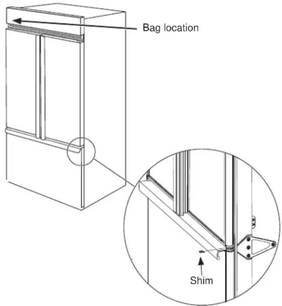
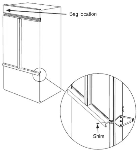
- Add or subtract shims as shown to adjust the right door only. More shims are located under the hood on the left side in the bag with the filter bypass plug and mini manual.
To Raise Right Hand Door
- Lift the right hand door up so there is a gap below the bottom hinge bushing.
- Snap a shim onto the hinge pin below the bushing.
- Lower the door and re-check the alignment.
- Repeat as necessary.
To Lower Right Hand Door
- Lift the right hand door up so there is a gap below the bottom hinge bushing.
- Remove a shim by pushing shim off of the hinge pin.
- Lower the door and re-check the alignment.
- Repeat as necessary.
Instructions for Flush Inset Installation
FLUSH INSET KIT ZKFN REQUIRED
The flush inset kit includes installation instructions, modified toe kicks, case assembly, and other required components.
Instructions for Stainless Steel Installation
THE INSTALLATION SPACE
Water And Electrical Locations
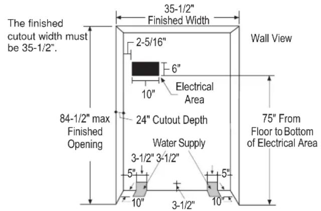
Electrical and water supply must be located as shown.
The cutout depth must be 24" (60.96 cm)
The refrigerator will project forward, slightly beyond adjacent cabinetry, depending on your installation. Allow minimum 1/8" (0.32 cm) air gap between case back & wall.
Cutout depth beneath a soffit:
When installed beneath a soffit, the soffit cannot exceed the 24" (60.96 cm) installation depth shown. The top case trim overlaps the bottom of the soffit.
Additional Specifications
- A 115 volt 60Hz., 15 or 20 amp power supply is required. An individual properly grounded branch circuit or circuit breaker is recommended. Install a properly grounded 3-prong electrical receptacle recessed into the back wall. Electrical must be located on rear wall as shown.
- Water line can enter the opening through the floor or back wall. Route SmartConnect™ kit or 1/4" O.D. copper tubing between the cold water line and the water connection location. The tubing should be long enough to extend to the front of the refrigerator. Installation of an easily accessible shut-off valve in the water line is required.
DIMENSIONS AND CLEARANCES
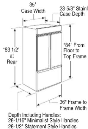
* Shipping height. The refrigerator can be adjusted to fit into a cutout that is 83-1/2" (212.09 cm) min. to 84-1/2" (214.63 cm) max. height. Note that the top case trim at the front is 1/2" higher and will overlap upper cabinetry or soffit. Use leveling legs and wheels for a maximum 1" (2.54 cm) height adjustment.
Product Clearances
These refrigerators are equipped with a 3-position door stop. The factory set 130° door swing can be adjusted to 90° if clearance to adjacent cabinets or walls is restricted.
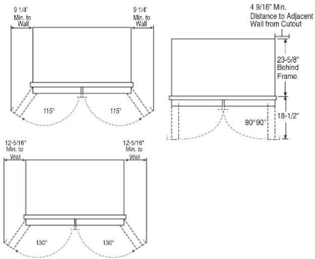
Allow 12-5/16" (31.27 cm) minimum clearance for a full 130° door swing.
For a 90° door swing, allow 4 9/16" (11.59 cm) min. clearance to a wall, for framed and stainless steel models. If the 90° door stop position is used, pan access is maintained, but pan removal is restricted.
See illustrations pages 27 and 28 to determine door swing interaction with adjacent cabinets or countertops.
CUSTOMIZATION BASICS:
Framed Or Overlay Panels, Custom Handles and Accessory Kits
Professional Style Stainless Steel Refrigerators
Stainless steel wrapped refrigerators with beveled edges and professional style handles. These models are shipped ready for installation.
Stainless Steel Wrapped Refrigerators
Stainless steel wrapped refrigerators with beveled edges and tubular stainless steel handles that coordinate with other Monogram appliances. These models are shipped ready for installation.
Side Panels
Side panels must be used whenever the sides of the refrigerator will be exposed.
REFRIGERATOR LOCATION
- Do not install the refrigerator where the temperature will go below 60^ F ( 16^ C). It will not run often enough to maintain proper temperatures.
- Do not install the refrigerator where temperatures will go above 100°F (37°C). It will not perform properly.
- Do not install the refrigerator in a location exposed to water (rain, etc.) or direct sunlight.
- Install it on a floor strong enough to support it fully loaded.
SIDE PANELS
Side panels must be used whenever the sides of the refrigerator will be exposed. The 1/4" (0.63 cm) side panels will slip into the side case trim. Secure the panels to the refrigerator with stick-on hook and loop fastener strips. Order the side panels from the cabinet manufacturer.
- Cut a notch in the top front corner as shown to allow clearance for corner keys in the front side trim.
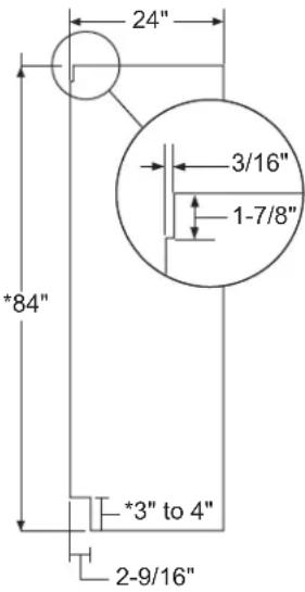
* Depending on installation height.
Design Guide - Stainless Steel Installation
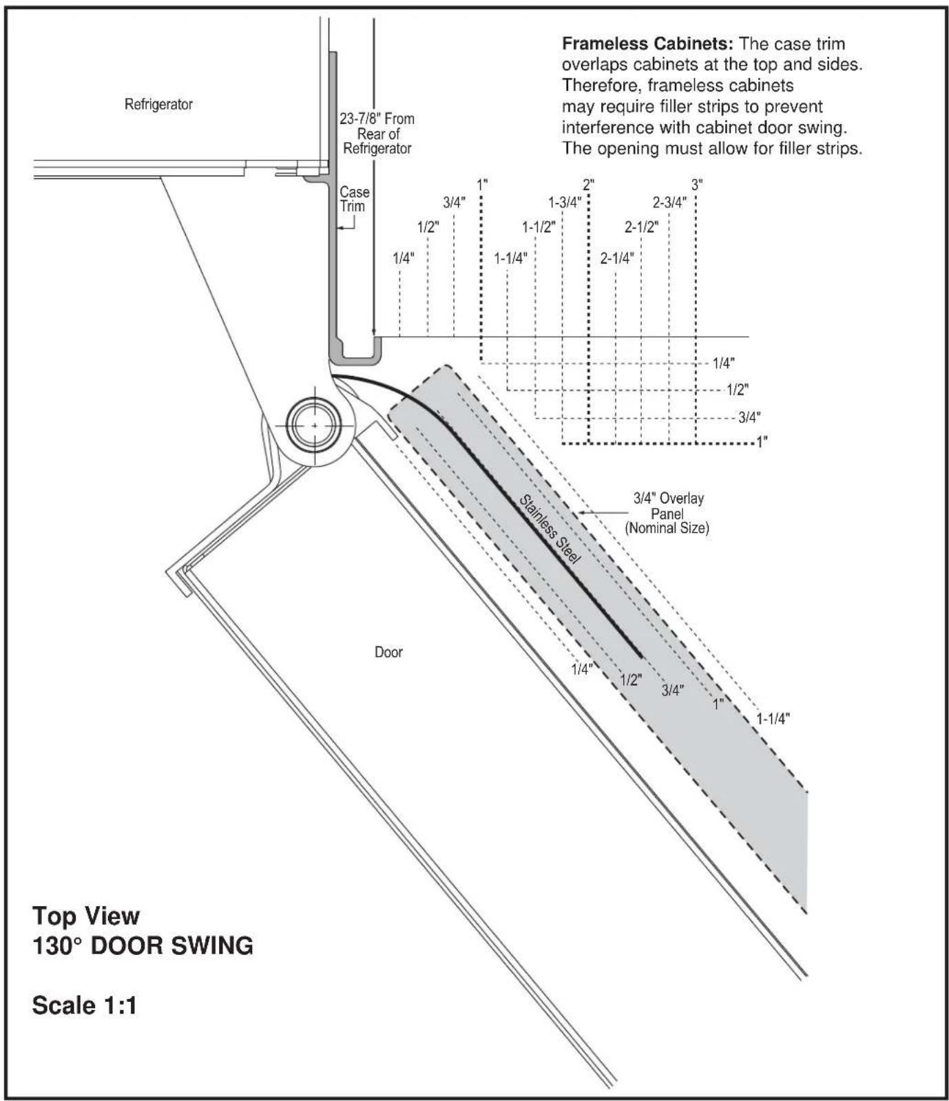
Design Guide - Stainless Steel Installation
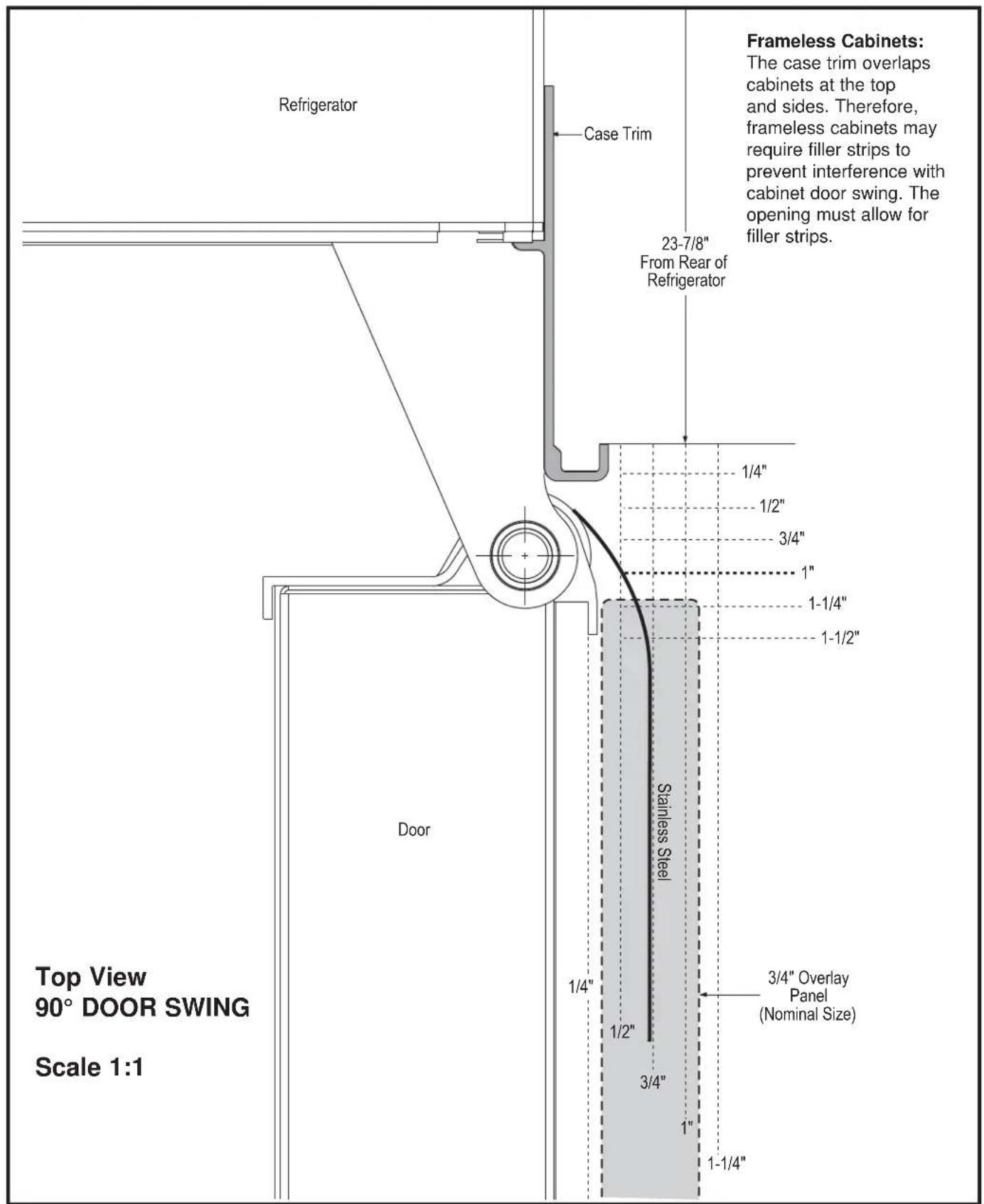
TOOLS REQUIRED
• Tinsnips to cut banding
- Stepladder
- Bucket
- Level
• Appliance Hand Truck
- Tubing cutter
- 7/16" open-end wrench
• #2 Phillips screwdriver
- Drill and appropriate bits
- 5/16", 7/16" socket
- Safety glasses
- 1-1/4" open end wrench
- Pliers
- 1/4" ratchet
HARDWARE SUPPLIED
• Water filter bypass plug
- Anti-Tip brackets
- 1/4" nut and ferrule
GROUNDING THE REFRIGERATOR
WARNING
Electrical Shock Hazard.
Failure to follow these instructions can result in death, fire, or electrical shock.
The power cord of this appliance is equipped with a 3-prong (grounding) plug which mates with a standard 3-prong (grounding) wall receptacle to minimize the possibility of electric shock hazard from this appliance.
Have the wall outlet and circuit checked by a qualified electrician to make sure the outlet is properly grounded.
Where a standard 2-prong wall outlet is encountered, it is your personal responsibility and obligation to have it replaced with a properly grounded 3-prong wall outlet.
DO NOT, UNDER ANY CIRCUMSTANCES, CUT OR REMOVE THE THIRD (GROUND) PRONG FROM THE POWER CORD.
DO NOT USE AN ADAPTER PLUG TO CONNECT THE REFRIGERATOR TO A 2-PRONG OUTLET.
DO NOT USE AN EXTENSION CORD WITH THIS APPLIANCE.
MATERIALS REQUIRED
- 35" (88.9 cm) long 2x4 for Anti-Tip support
- 1/4" copper water line tubing or SmartConnect™ Refrigerator Tubing kits
• Water shut-off valve - Custom panels for fresh food door, freezer drawer and grille panel
- Screws to secure refrigerator to cabinetry.
- Stick-on hook and loop fastener strips for 1/4" side panels
FLOORING
For proper installation, this refrigerator must be placed on a level surface of hard material that is at the same height as the rest of the flooring. This surface should be strong enough to support a fully loaded refrigerator, or approximately 1,200 lbs. (544.31 cm).
NOTE: Protect the finish of the flooring. Cut a large section of the cardboard carton and place under the refrigerator where you are working.
MISE À LA TERRE DU RÉFRIGÉRATEUR
▲AVERTISSEMENT

Risque de choc
électrique.
NE COUPEZ PAS OU N'ENLEVEZ
PAS, SOUS AUCUN PRÉTEXTE, LA TROISIÈME BROCHE DE MISE À LA TERRE DU CORDON D'ALIMENTATION.
N'UTILISEZ PAS D'ADAPTATEUR POUR BRANCHER LE
RÉFRIGÉRATEUR À UNE PRISE BIPHASÉE. N'UTILISEZ PAS DE RALLONGE AVEC CET APPAREIL.
Refrigerator is much heavier at the top than at the bottom. To avoid a risk of death or serious injury, be careful when moving, and when using a hand truck, handle only from side.
DO NOT ATTEMPT TO ROLL UNIT OFF SKID.
AVERTISSEMENT

- Carefully cut banding at the top and bottom, remove the outer carton.
- Slide out the back corner posts (2).
- Slide the carton off the top of the cabinet.
NOTE: IT IS NOT NECESSARY TO LAY THE CABINET DOWN IN ORDER TO REMOVE THE SKID!
- The unit is secured to the skid with 2 full-length tie-down straps. Remove the ten 5/16" bolts from the base channels in the tie-downs.
- Remove the four 7/16" bolts securing the straps to the skid.
NOTE: DO NOT ATTEMPT TO ROLL UNIT OFF SKID.
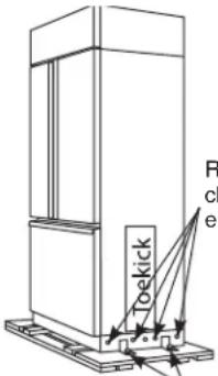
Remove 5 base channel bolts on each side
Remove 2 strap bolts on each side
- The support blocks on the bottom of the refrigeration case must be removed before the refrigerator is taken off the skid or damage will occur. Carefully tilt the refrigerator and slide the blocks out from beneath.
- Remove the toekick and set aside for final installation.
- Lift the refrigerator off the skid with an appliance dolly. Handle from the sides.
STEP 2 INSTALL WATER LINE
WARNING
Connect to potable water supply
only. A cold water supply is required for automatic icemaker operation. The water pressure must be between 40 and 120 psi (275-827 kilopascals).
WARNING

ELECTRIC SHOCK HAZARD
Attach tubing clamp using existing hole only. DO NOT drill into the refrigerator.
AVERTISSEMENT
- A cold water supply is required for automatic icemaker operation. The water pressure must be between 40 and 120 p.s.i. (275-827 kPa).
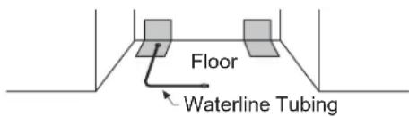
- Route 1/4" OD copper or SmartConnect™ plastic tubing between house cold water line and the water connection location.
- Tubing should be long enough to extend to the front of the refrigerator. Allow enough tubing to accommodate bend leading into the water line connection.
STEP 2 INSTALL WATER LINE
(Cont.)
NOTE: The only Monogram Appliances-approved plastic tubing is supplied in the SmartConnect™ Refrigerator Tubing kits. Do not use any other plastic water supply line because the line is under pressure at all times. Other types of plastic may crack or rupture with age and cause water damage to your home.
SmartConnect™ Refrigerator Tubing Kits are available in the following lengths:
2' (.6 m) WX08X10002
8' (2.4 m) WX08X10006
15' (4.6 m) WX08X1 0015
25' (7.6 m) WX08X10025
Shut off the main water supply.
Turn on the nearest faucet long enough to clear the line of water.
- Install a shut-off valve between the icemaker water valve and cold water pipe in a basement or cabinet. The shut-off valve should be located where it will be easily accessible.
- Turn on the main water supply and flush debris. Run about a quart of water through the tubing into a bucket. Shut off water supply at the shut-off valve.
NOTE: Saddle type shut-off valves are included in many water supply kits, but are not recommended for this application.
NOTE: Commonwealth of Massachusetts Plumbing Codes 248CMR shall be adhered to. Saddle valves are illegal and use is not permitted in Massachusetts. Consult with your licensed plumber.
STEP 2A WATER LINE INSTALLATION WITH A REVERSE OSMOSIS SYSTEM OR OTHER HOUSEHOLD FILTRATION SYSTEM
Skip this step when not using an RO System or other household filtration system.
If the water supply to the refrigerator is from a household filtration system, use the refrigerator's filter bypass plug. Using the refrigerator's water filtration cartridge with the RO filter can result in hollow ice cubes.
STEP 3 INSTALL SIDE PANELS
Skip this step when not using side panels If you are using 1/4" (0.63 cm) side panels, they should be inserted into the case trim. Fasten the panels to the refrigerator with stick-on hook and loop fastener strips before setting refrigerator in place.
STEP 4 ANTI-TIP PROCEDURE
WARNING
Over Hazard.
These refrigerators are top heavy, especially with any doors open, and must be secured to prevent tipping forward which could result in death or serious injury. Read and follow the entire installation instructions for securing the refrigerator with the anti-tip system.
AVERTISSEMENT
de
basculement
- The kit supplied with the unit contains 2 lag bolts and 4 toggles with bolts. The wall bracket will be attached to the wall in 4 places.
- Measure the opening where the unit is to be installed. Mark the center with a vertical line.
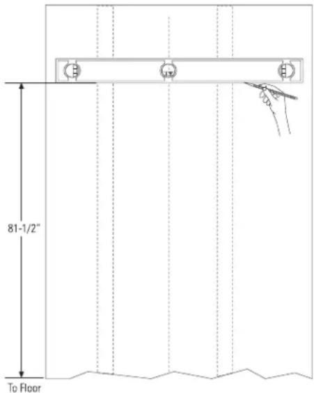
- Measure up 81 1/2" (207.01 cm) from the floor. Mark this point on the wall.
• Using a level, draw a horizontal line on the wall at this height.
STEP 4 ANTI-TIP PROCEDURE (CONT)
- Locate at least 2 studs on the back wall. Mark these points on the horizontal line.
- Place the bottom of the wall bracket with tabs on the horizontal line. Align the center notch on the bracket with the center line on the wall.
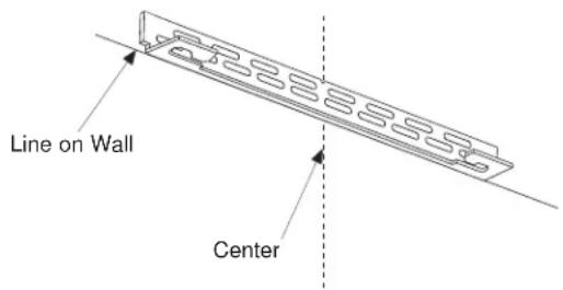
- The anti-tip wall bracket has a series of holes. Select 2 holes that match with the located studs. Make sure the holes selected are on the center of the studs. Mark the wall at these points.
- Mark an additional hole at each end of the bracket. If one of the studs is closer to the end of the bracket, mark an additional hole towards the center of the bracket.
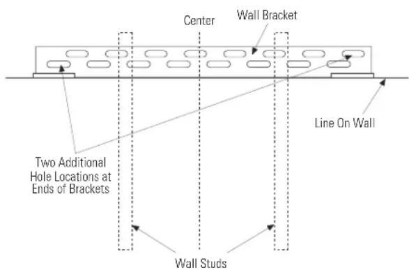
- Drill 1/2" (1.27 cm) holes into the wall board at the locations marked for the toggles to be mounted (not the stud markings).
- Drill 3/16" (0.47 cm) holes into wooden studs where marked. If steel stud construction, drill 1/2" (1.27 cm) holes into the studs where marked. You will use 2 toggles with the metal studs.
STEP 4 ANTI-TIP PROCEDURE (CONT)
Install Wall Toggles:
The wall toggles and bolts can be ordered as Service Kit #WR49X10193. Wall toggles are installed in the drywall and metal studs for stability. Install the wall toggles as follows:
- Drill 1/2" (1.27 cm) holes at the wall markings made in the holes at the ends of the wall bracket.
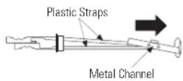
- Hold the metal channel flat against the plastic straps and slide the channel through the hole.
- Gently pull back at the ends of the plastic straps to make the channel rest flush behind the wall.
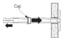
- Hold the ends of the straps in one hand and slide the plastic cap along the straps until the flange of the cap is flush with the wall.
- Place your thumb between the plastic straps and bend up and down to snap the straps off at the wall.

natural_image
Mechanical lever diagram showing a lever with an arrow indicating direction (no text or symbols)Install Screws and Bolts:
- Have someone hold the wall bracket centered in place with each of the holes aligned with the correct opening in the bracket and level with the horizontal line.
- Insert the lag screws through the bracket and into the stud. Tighten with a wrench.
- Insert the bolts into the toggle by hand until snug. Tighten with a wrench.
STEP 4 ANTI-TIP PROCEDURE (CONT)
CONNECT POWER CORD:
- Before pushing the refrigerator into the opening, plug the power cord into the receptacle. Open the grille panel and reach into the opening at the back to grasp the power cord. Pull the power cord into the opening as you push the refrigerator back.
- Gently push refrigerator into the opening with hands against front corners.
IMPORTANT: When the refrigerator is installed under a soffit or if there is not enough height for this method of security, brackets cannot be used. Proceed to step 5 to level the refrigerator and then to step 7 to secure refrigerator to cabinets.
STEP 5 LEVEL REFRIGERATOR
All models have 4-point leveling. The front is supported by leveling legs, the rear is supported by adjustable wheels. Both are accessible from the front of the refrigerator.
- To level the back of the refrigerator, turn the 7/16" hex nut located above the front wheels. Turn clockwise to raise or counterclockwise to lower the refrigerator.
- For front leveling, use a 1-1/4" open-end wrench.
- Adjust height of refrigerator to match installation cutout opening 83-1/2" (212.09 cm) to 84-1/2" (10.16 cm). The refrigerator should be level and plumb with cabinetry.
The rear leveling wheels and front leveling legs are limited to a maximum height adjustment of 1". If the installation requires more than 84-1/2" height, the installer should elevate the refrigerator on a sheet of plywood or runners. Cabinetry trim could also be added across the top of the opening to shorten the opening. If you attempt to raise the refrigerator more than 1", you will damage the front leveling legs and the rear leveling wheels.
STEP 6 SECURE UNIT TO WALL
- The "L" rod can be found in the upper left corner of the unit in the access compartment. Look through the access compartment to make sure the rod lines up with the anti-tip bracket.
- There are 2 washers and a hair pin cotter with the rod. Remove the washers and hair pin cotter from the end of the rod.
- Rotate and move the "L" rod into the slot in the anti-tip bracket tab. Once it is in the slot, rotate the "L" rod so the hook portion is pointing down. The holes at the front end of the rod should be in a vertical position.
- Pull out on the end of the rod to make sure it is secure in the bracket.
- Locate the hole on the rod that is closest to the unit. A hair pin cotter will be put through this hole to secure the rod. If this hole appears to be too far away for a snug fit against the unit, add the washers one at a time until the pin will fit tightly into the hole.
- Align the straight section of the pin with the hole from the underside of the rod. Push the pin up until it snaps into position. Pliers may be used.
NOTE: The hair pin cotter must be vertical when this step is completed to ensure the "L" rod is engaged in the bracket.
- Check the rod for tightness by pulling forward. If the rod moves, remove the hair pin cotter and place another washer on the rod. Reinsert the pin.
STEP 7 ALTERNATE ANTI-TIP PROCEDURE
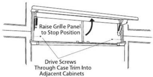
The refrigerator must be secured to prevent tipping. If the anti-tip bracket cannot be used, this alternate procedure may be used to secure the refrigerator against tip-over
- Raise the grille panel to access case trim.
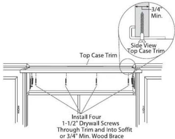
- Use a 3/16" bit to drill four evenly spaced clearance holes through the metal top case trim.
- Use a 1/16" bit to drill to pilot holes through the metal clearance holes and into the wood soffit. The holes should be centered in the soffit or a 3/4" min. wood brace. The brace spanning the enclosure must be securely fastened to cabinets on both sides.
- Install four, 1-1/2" (3.81 cm) drywall screws into the pilot holes.
- If no soffit above the unit, drill screws into adjacent cabinets through the side case trim.
STEP 8 ADJUST DOOR SWING
NOTE: This refrigerator has a 3-position door stop. When space does not allow the door to swing open fully to 130°, you may change the door swing to a 115° or 90° opening. Skip this step if door opening is satisfactory for your installation situation.
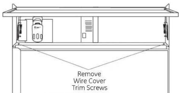
- Lift the grille panel to access the wire cover trim.
- Remove screws on both sides of the wire cover trim and rotate off.
- Use pliers to unscrew door stop and reinstall into the 90^ or 115^ position.
Pin Location
for 90°
Door Swing
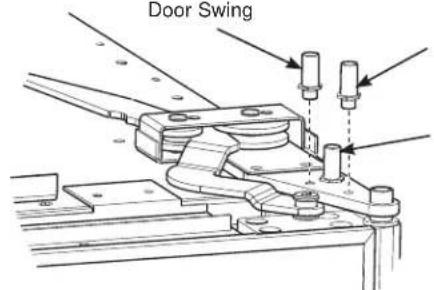
Pin Location
as Shipped 130°
Door Swing
Pin Location
for 115°
Door Swing
- Reinstall the wire cover trim.
STEP 9 CONNECT WATER SUPPLY
WARNING
Connect to potable water supply only. A cold water supply is required for automatic icemaker operation. The water pressure must be between 40 and 120 psi (275-827 kilopascals).
WARNING

.ECTRIC SHOCK HAZARD
Attach tubing clamp using existing hole only. DO NOT drill into the refrigerator.
AVERTISSEMENT
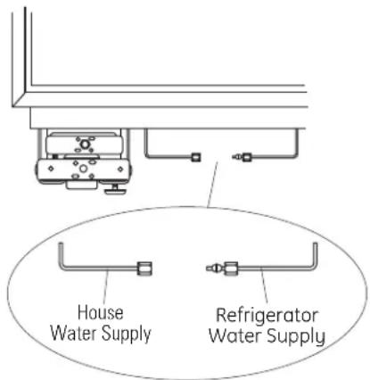
- Locate and bring tubing to the front of the cabinet.
- Turn the water on to flush debris from line. Run about a quart of water through tubing into a bucket, then shut off water.
STEP 9 CONNECT WATER SUPPLY
(Cont.)
Copper Tubing:
- Slip a 1/4" nut and ferrule (provided) over both ends of the copper tubing. Insert tube into the union fitting on the unit and tighten nut to union.
- Turn on the water to check for leaks.
SmartConnect™ Tubing:
NOTE: The only Monogram Appliances-approved plastic tubing is supplied in the SmartConnect™ Refrigerator Tubing kits. Do not use any other plastic water supply line because the line is under pressure at all times. Other types of plastic may crack or rupture with age and cause water damage to your home.
- Insert the molded end of the tubing into the refrigerator connection. Tighten the compression nut until it is just hand tight.
- Tighten one additional turn with a wrench. Overtightening can cause leaks!
- Turn on the water to check for leaks.
NOTE: Make sure excess tubing length does not interfere with drawer closing or toekick installation.
STEP 10 CONNECT POWER
- Check to be sure the power cord is plugged into the receptacle.
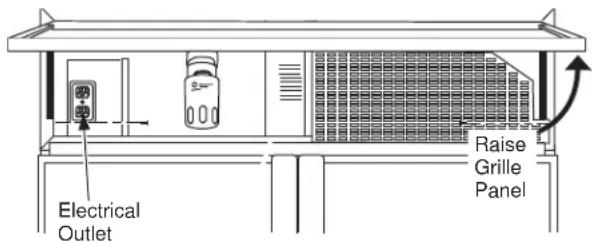
- Check to make sure power to refrigerator is on by opening refrigerator door to see if interior lights are on.
- The temperature controls are preset at 37^ for the fresh food section and 0^ for the freezer.
- Allow 24 hours to stabilize before making adjustments.
STEP 11 START ICEMAKER
CAUTION
To minimize the risk of personal injury, avoid contact with the moving parts of the ejector mechanism, or with the heating element that releases the cubes. Do not place fingers or hands on the automatic ice making mechanism while the appliance is plugged in.
ATTENTION
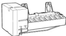
- The icemaker will begin operation automatically.
- Be sure nothing interferes with the sweep of the feeler arm.
- Discard the first full bucket of ice cubes.
- To turn the icemaker off, set the switch to O (OFF).
NOTE: Icemaker works best between 40 and 120 PSI (275-827 kPa) home water pressure.
natural_image
Technical line drawing of a mechanical device with no visible text or symbolsSTEP 12 INSTALL TOEKICK
- Locate the supplied toekick (shipped taped to the side of the refrigerator). Install the toekick assembly with the 2 screws provided, adjust to the desired height and tighten the screws.

natural_image
Technical line drawing of a rectangular panel with internal grating and mounting holes (no text or symbols)IMPORTANT: A custom toekick can be installed to match or complement the surrounding cabinetry but can NOT cover the horizontal vent slots of the factory toe kick.
INSPECT FINAL INSTALLATION
Check Door Alignment
Stand back away from the refrigerator to inspect the final installation.
- Installation or the addition of heavy door panels may have caused the doors to move slightly out of alignment. Check to be sure the top of the doors are evenly aligned with each other. If necessary, the doors may be adjusted up or down to align.
- Add or subtract shims as shown to adjust the right door only. More shims are located under the hood on the left side in the bag with the filter bypass plug and mini manual.
To Raise Right Hand Door
- Lift the right hand door up so there is a gap below the bottom hinge bushing.
- Snap a shim onto the hinge pin below the bushing.
- Lower the door and re-check the alignment.
- Repeat as necessary.
To Lower Right Hand Door
- Lift the right hand door up so there is a gap below the bottom hinge bushing.
- Remove a shim by pushing shim off of the hinge pin.
- Lower the door and re-check the alignment.
- Repeat as necessary.
Installation Instructions back page.
NOTE: While performing installations described in this book, safety glasses or goggles should be worn.
NOTE: Product improvement is a continuing endeavor at Monogram. Therefore, materials, appearance and specifications are subject to change without notice.

MONOGRAM
INSTRUCTIONS D'INSTALLATION
Inspect Final Installation 19
Inspect Final Installation 32
natural_image
Mechanical assembly diagram showing a screw inserted into a plate, with a separate view of a bulb (no text or symbols present)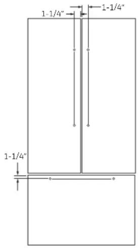
RENSEIGNEMENTS SUR LA PERSONNALISATION :
Guide de conception – Installation standard
natural_image
Pure mechanical diagram showing a lever mechanism with an arrow indicating direction (no text or symbols)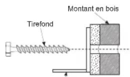
Support mural antibasculement
natural_image
Pure mechanical diagram showing a lever mechanism with rotational motion arrows (no text or symbols)natural_image
Technical line drawing of a mechanical or electrical enclosure unit with no visible text or symbolsnatural_image
Simple diagram of a rectangular container with two upward arrows inside, no text or symbols present.ÉTAPE 10 INSTALLER LES PANNEAUX ENCADRÉS 1/4 po (0,63 cm)
SI VOUS INSTALLEZ DES PANNEAUX DE RECOUVREMENT, ALLEZ À L'ÉTAPE 10A.
natural_image
Technical diagram of a door mechanism with an arrow indicating direction, shown in two views (top: vertical and horizontal; bottom: close-up of a vertical component)natural_image
Technical line drawing of a mechanical assembly with a downward arrow symbol (no text or labels)ÉTAPE 10A INSTALLER LES PANNEAUX DE RECOUVREMENT
SI VOUS INSTALLEZ DES PANNEAUX ENCADRÉS, ALLEZ À L'ÉTAPE 10.
natural_image
Architectural diagram showing a wall-mounted directional arrow with a black arrow symbol, mounted on a shelf (no text or labels)natural_image
Technical line drawing of an electrical component with no visible text or symbolsnatural_image
Technical line drawing of a rectangular panel with ventilation slots and mounting points (no text or symbols)Guide de conception – Installation en acier inoxydable
ÉTAPE 4 DISPOSITIF ANTIBASCULEMENT (suite)
natural_image
Technical line drawing of a mechanical component with no visible text or symbolsÉTAPE 12 INSTALLER LE COUP-DE-PIED
natural_image
Technical line drawing of a rectangular panel with internal grating and mounting holes (no text or symbols)natural_image
Mechanical assembly diagram showing a screw inserted into a plate, with a separate view of a cylindrical component (no text or symbols)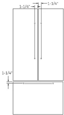
| Comida Fresca Freezer Rejilla | |||
| Panel de Soporte de 1/4" (0.63 cm) | 46-1/16" x 16-1/2" (116.99 x 14.91 cm) | 33-7/8" x 21-7/8" (86.04 x 55.56 cm) | 33-7/8" x 8-7/8" (86.04 x 22.54 cm) |
| Panel Separador de 0.10" (0.25 cm) | 44-11/16" x 15" (113.51 x 38.10 cm) | 32-1/2" x 20-1/2" (82.55 x 52.07 cm) | 32-1/2" x 7-5/8" (82.55 x 19.37 cm) |
| Panel Revestido de 3/4" (1.9 cm) | 46-5/16" x 16-5/8" (117.63 x 42.23 cm) | 34-1/8" x 22" (96.67 x 55.88 cm) | 34-1/8" x 9" (96.67 x 22.86 cm) |
| Panel con Marco de 1/4" (0.63 cm) | 46-1/16" x 16-1/2" (101.76 x 41.91 cm) | 33-7/8" x 21-7/8" (86.04 x 55.56 cm) | 33-7/8" x 8-7/8" (86.04 x 22.54 cm) |
natural_image
Diagram of a lever mechanism with an arrow indicating direction (no text or symbols present)PASO 4 PROCEDIMIENTO ANTI- VOLCADURAS (Cont.)
natural_image
Technical line drawing of a mechanical or electrical enclosure with no visible text or symbolsnatural_image
Diagram of a container with two upward arrows indicating flow or movement (no text or symbols)natural_image
Architectural diagram showing a cabinet with a double-headed arrow symbol, no text or labels presentnatural_image
Technical line drawing of a mechanical assembly with a downward arrow symbol (no text or labels)natural_image
Technical line drawing of a mechanical component with no visible text or symbolsPASO 14 INSTALE EL ZÓCALO
natural_image
Technical line drawing of a rectangular ventilation duct with mounting holes and ventilation slots (no text or symbols)natural_image
Diagram of a mechanical lever system with an arrow indicating direction (no text or symbols present)PASO 4 PROCEDIMIENTO ANTI- VOLCADURAS (Cont)
natural_image
Technical line drawing of a mechanical component with no visible text or symbolsPASO 12 INSTALE EL ZÓCALO
natural_image
Technical line drawing of a rectangular electronic component with ventilation slots and mounting holes (no text or symbols)- WARNING
- Electrical Shock Hazard.
- ver Hazard.
- or Explosion Hazard.
- CAUTION
- Lifting Hazard
- Instructions for Standard Installation 6
- Design Guide
- Installation Instructions
- Instructions for Flush Inset Installation 24
- Instructions for Stainless Steel Installation 25
- Instructions for Standard Installation
- Water And Electrical Locations
- The cutout depth must be 24" (60.96 cm)
- Cutout depth beneath a soffit:
- Additional Specifications
- Product Clearances
- CUSTOM HANDLE DESIGN GUIDE
- CUSTOMIZATION BASICS:
- Framed Or Overlay Panels, Custom Handles and Accessory Kits
- Side Panels
- REFRIGERATOR LOCATION
- OPTIONAL ACCESSORY KITS
- 3/4" (1.91 cm) OVERLAY PANEL DIMENSIONS
- 1/4" (0.63 cm) FRAMED PANEL DIMENSIONS
- Design Guide - Standard Installation
- Installation Instructions - Standard Installation
- TOOLS REQUIRED
- MATERIALS REQUIRED
- HARDWARE SUPPLIED
- FLOORING
- GROUNDING THE REFRIGERATOR
- ⚠ WARNING
- MISE À LA TERRE DU RÉFRIGÉRATEUR
- ▲AVERTISSEMENT
- Risque de choc
- électrique.
- NOTE: DO NOT ATTEMPT TO ROLL UNIT OFF SKID.
- STEP 1 REMOVE PACKAGING
- AVERTISSEMENT
- de basculement
- .ECTRIC SHOCK HAZARD
- STEP 2 INSTALL WATER LINE
- (Cont.)
- Shut off the main water supply.
- STEP 2A WATER LINE INSTALLATION WITH A REVERSE OSMOSIS SYSTEM OR OTHER HOUSEHOLD FILTRATION SYSTEM
- STEP 3 INSTALL SIDE PANELS
- STEP 4 ANTI-TIP PROCEDURE
- STEP 4 ANTI-TIP PROCEDURE (CONT)
- Install Wall Toggles:
- Install Screws and Bolts:
- CONNECT POWER CORD:
- STEP 5 LEVEL REFRIGERATOR
- STEP 5 LEVEL REFRIGERATOR (Cont.)
- STEP 6 SECURE UNIT TO WALL
- STEP 7 ALTERNATE ANTI-TIP PROCEDURE
- STEP 8 ADJUST DOOR SWING
- STEP 9 INSTALL GRILLE PANEL
- STEP 10 INSTALL 1/4" (0.63 cm) FRAMED PANELS
- IF YOU ARE INSTALLING OVERLAY PANELS, GO TO STEP 10A.
- Install door and drawer panels:
- STEP 10A INSTALL OVERLAY PANELS IF YOU ARE INSTALLING FRAMED PANELS, GO TO STEP 10.
- STEP 11 CONNECT WATER SUPPLY
- LECTRIC SHOCK HAZARD
- Copper Tubing:
- STEP 11 CONNECT WATER SUPPLY (Cont.)
- SmartConnect™ Tubing:
- STEP 12 CONNECT POWER
- STEP 13 START ICEMAKER
- ATTENTION
- STEP 14 INSTALL TOEKICK
- INSPECT FINAL INSTALLATION
- Check Door Alignment
- To Raise Right Hand Door
- To Lower Right Hand Door
- Instructions for Flush Inset Installation
- FLUSH INSET KIT ZKFN REQUIRED
- Instructions for Stainless Steel Installation
- Professional Style Stainless Steel Refrigerators
- Stainless Steel Wrapped Refrigerators
- Design Guide - Stainless Steel Installation
- ELECTRIC SHOCK HAZARD
- basculement
- STEP 9 CONNECT WATER SUPPLY
- STEP 10 CONNECT POWER
- STEP 11 START ICEMAKER
- STEP 12 INSTALL TOEKICK
- INSTRUCTIONS D'INSTALLATION
- RENSEIGNEMENTS SUR LA PERSONNALISATION :
- Guide de conception – Installation standard
- ÉTAPE 10 INSTALLER LES PANNEAUX ENCADRÉS 1/4 po (0,63 cm)
- Guide de conception – Installation en acier inoxydable
- ÉTAPE 4 DISPOSITIF ANTIBASCULEMENT (suite)
- ÉTAPE 12 INSTALLER LE COUP-DE-PIED
- PASO 4 PROCEDIMIENTO ANTI- VOLCADURAS (Cont.)
- PASO 14 INSTALE EL ZÓCALO
- PASO 4 PROCEDIMIENTO ANTI- VOLCADURAS (Cont)
- PASO 12 INSTALE EL ZÓCALO
Brand : Monogram
Model : ZIPS360NNSS
Category : Refrigerator