FZT-250/1500 - Jigsaw Ferm - Free user manual and instructions
Find the device manual for free FZT-250/1500 Ferm in PDF.


| Product Type | Electric Jigsaw |
| Brand | Ferm |
| Model | FZT-250/1500 |
| Power Supply | Mains 230 V ~ 50 Hz |
| Rated Power | 500 W |
| No-load Speed | 500 - 3000 strokes/min (adjustable) |
| Blade Stroke | 20 mm |
| Max Cutting Capacity (wood) | 80 mm |
| Max Cutting Capacity (steel) | 6 mm |
| Cutting Angle | 0° - 45° (adjustable) |
| Blade Type | T-shank blade (universal) |
| Net Weight | 2.2 kg |
| Dimensions (L × W × H) | 240 × 80 × 200 mm |
| Sound Level (LpA) | 78 dB(A) |
| Vibration Level (hand/arm) | 6.5 m/s² |
| Protection Class | II (double insulation) |
| Main Features | Straight, curved, plunge cutting, chip blower, integrated LED lighting, variable speed, switch lock |
| Maintenance and Cleaning | Clean tool with a dry cloth after use, lubricate the blade guide regularly, replace carbon brushes if necessary |
| Safety | On/off switch with continuous lock, anti-restart protection, reinforced cable sheath |
| Spare Parts and Repairability | Replacement blades, protective shoe, motor carbon brushes available. Repair possible at authorized center |
| Package Contents | Jigsaw, 1 wood blade, parallel guide, hex key, instruction manual |
Frequently Asked Questions - FZT-250/1500 Ferm
User questions about FZT-250/1500 Ferm
0 question about this device. Answer the ones you know or ask your own.
Ask a new question about this device
Download the instructions for your Jigsaw in PDF format for free! Find your manual FZT-250/1500 - Ferm and take your electronic device back in hand. On this page are published all the documents necessary for the use of your device. FZT-250/1500 by Ferm.
USER MANUAL FZT-250/1500 Ferm
natural_image
Exterior view of a metal filing machine with visible components and wheels (no text or symbols on the device itself)GB) USERS MANUAL 05
natural_image
Close-up of a mechanical clamp or bracket assembly with a finger inserted, showing no visible text or symbols.Fig. D-2

natural_image
Close-up of a transparent plastic enclosure with warning signs and an arrow indicating rotation (no readable text or symbols)Fig. E-1

natural_image
Close-up of a metallic industrial machine with a transparent cover and internal cavity (no visible text or symbols)Fig. E-2

Fig. E-1
natural_image
Close-up of a hand holding a small electronic device with a curved arrow symbol on the side (no text or symbols visible)Fig. F-1
natural_image
Close-up of a hand using a screwdriver to test or inspect a component with a circular arrow symbol (no text or symbols present)Fig. F-2

natural_image
Close-up of hands operating a mechanical device with a magnified inset showing a close-up of a component (no visible text or symbols)Fig. F-3

natural_image
Close-up of a hand using a screwdriver to work on a wooden table, with tools and a hammer visible (no text or symbols)Fig. F-4

natural_image
Close-up of a hand using a stationary exercise machine to adjust a cable, no visible text or symbolsFig. G-1
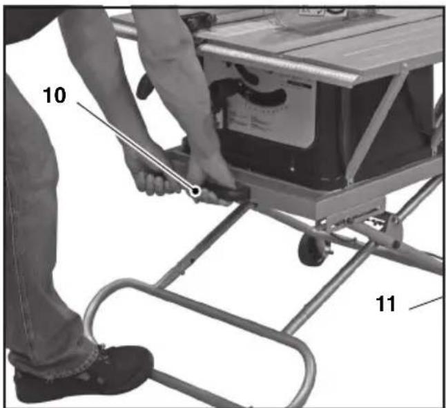
Fig. G-2

natural_image
Close-up of a gray plastic mechanical component with ventilation grilles and mounting holes (no text or symbols visible)Fig. F-1
TABLE SAW

Always read the instruction for electrical products carefully before use. It will help you understand your product more easily and avoid unnecessary risks. Keep this instruction manual in a safe place for future use.
Contents
- Technical specifications
- Safety instructions
- Assembly instructions
- Operation
- Maintenance
1. TECHNICAL SPECIFICATIONS
Voltage 230-240 V\~
Frequency 50 Hz
Power input 1500 W
No load speed 4500/min
Saw blade dimensions 254x16x2.8mm
Number of teeths Z40
Measurements of bench 667x430 mm
Dust extraction outlet 30(20) mm
Weight 37 kg
Lpa (sound pressure level) 99.3 dB(A)
Lwa (sound power level) 112.3 dB(A)
Product information
Fig. A
- Protective cap
- Fence
- Bench inlay
- Mitre handle
- Height handle
- Measurement set-up for fence
- On/off switch
- Thermic safety switch
- Height adjustment handle for stand
- Handgrip
- Brake
- Rubber foot
- Nut for rubber foot
- Nuts and bolts for support foot
- Support foot
- Stand
Check first whether or not the delivery has been damaged by transport and/or whether all the parts are present.
2. SAFETY INSTRUCTIONS
Explanation of symbols
In this manual and/or on the machine the following symbols are used:

Read instructions carefully.

In accordance with essential applicable safety standards of European directives.

Denotes risk of personal injury, loss of life or damage to the tool in case of non-observance of the instructions in this manual.

Indicates electrical shock hazard.

Immediately unplug the plug from the mains electricity in the case that the cord gets damaged and during maintenance.

Keep bystanders away.

Wear a dust mask. Working with wood, metals or other materials may produce dust that is harmful to health. Do not work with materials containing asbestos!

Wear ear and eye protection.

Faulty and/or discarded electrical or electronic apparatus have to be collected at the appropriate recycling locations.
Device-specific safety information Safety measures
- Do not use deformed or cracked saw blades.
- Replace a worn table insert.
- Only use saw blades recommended by the manufacturer complying with the requirements of EN 847-1. When changing the saw blade, ensure that the width of cut is not less and the saw blade body is not thicker than the thickness of the splitting wedge.
- Only use a saw blade that is suitable for the material to be cut.
- If necessary wear suitable personal protective equipment.
These could include:
- Hearing protectors for reducing the risk of hearing impairment.
- Respiratory protection for reducing the risk of inhaling harmful dust.
- Wear gloves when handling saw blades and rough materials.
Saw blade must always be carried in a container where practical.
- When sawing wood, circular saws must be connected to a sawdust collector.
- Do not use saw blades of high-alloy high-speed steel (HSS steel).
- The push stick must be kept at the machine when not in use.
Maintenance and service
- Defects in the machine, including guards and the saw blade must be reported to the person responsible for safety immediately upon their discovery.
Safe operation
- Use the push stick or handle with sliding block to guide the workpiece safely along the saw blade.
- Use the splitting wedge and adjust correctly.
- Use the upper saw blade guard and adjust correctly.
- Do not make rebates or grooves without using suitable a suitable guard such as a tunnel guard fitted above the saw table.
- Circular saws must not be used for slitting (groove completed in workpiece).
-
Only use saw blades the maximum speed of which is not slower than the maximum spindle speed of the circular saw bench.
-
When transporting the machine, only use the transport devices and never the guards for handling or transport purposes.
- The upper part of the saw blade should be covered, e.g. with guard during transport.
Further important information
• Always use the guards when making longitudinal and cross cuts.
• Always press the workpiece firmly against the longitudinal or mitre stop.
• Always use a push stick when rip-cutting narrow workpieces.
- Never reach behind or above the saw blade.
- Remove the longitudinal stop when making cross cuts.
- Never attempt to release a jammed saw blade without switching off the saw first. Switch off the saw immediately to prevent damage to the motor.
- Never attempt to release workpieces without switching off the saw first. Do not reach into the area of the rotating saw blade.
- Ensure that the end and sides of the saw table are sufficiently supported to prevent wide or long workpieces from tilting.
- Avoid workpiece rebound by:
- always using a sharp saw blade
- parallel alignment of the parallel stop to the saw blade
- gripping the workpiece until it has been pushed fully through the saw blade.
-
no ripping of distorted or deformed workpieces without straight edge that can be guided along the longitudinal stop.
-
Avoid changing hands and gripping positions where hands are liable to slip and make contact with the saw blade.
- Only use the saw to cut wood or similar materials.
Before use, remove the transport protection:
- Disassemble the bottom plate by loosening the 4 screws.
- Remove the transport protection below motor.
- The handles for height and mitre setting of the saw blade are located in the transport protection inside the machine.
- Reassemble the bottom plate.
Switch off the machine immediately when you discover:
• A defective mains plug or mains lead;
• A defective switch.
• Overheating of the machine.
- Smoke or odeur caused by scorched insulation.
Electrical safety
When using electric machines always observe the safety regulations applicable in your country to reduce the risk of fire, electric shock and personal injury. Read the following safety instructions and also the enclosed safety instructions.

Always check that the power supply corresponds to the voltage on the rating plate.
Replacing cables or plugs
Immediately throw away old cables or plugs when they have been replaced by new ones. It is dangerous to insert the plug of a loose cable in the wall outlet.
Using extension cables
- As a supply for this machine always use an unloaded line and/or an extension cable with conductors of at least 1,5 mm ^2 and protected with a 16 A fuse. Be sure that this extension cable is not longer than 20 metres.
- Only connect your machine and/or extension cable to an earthed electricity mains.
- This machine can be switched to the single-phase network (230 V/50 Hz). If you are in doubt about the earth of the electricity provisions, consult an electrician first.
3. ASSEMBLY INSTRUCTIONS
Assembly of the bench extensions
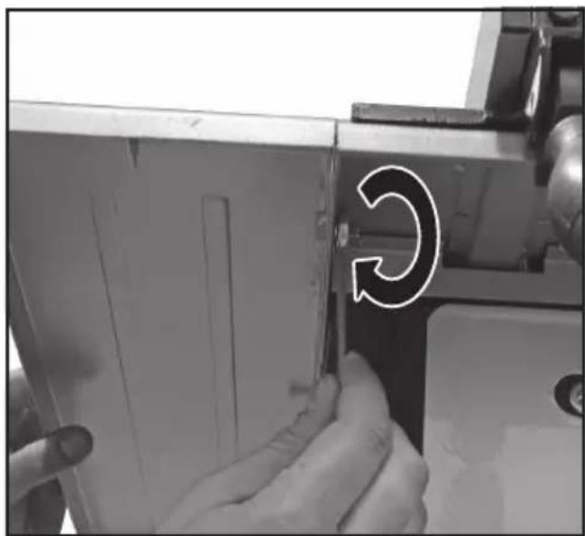
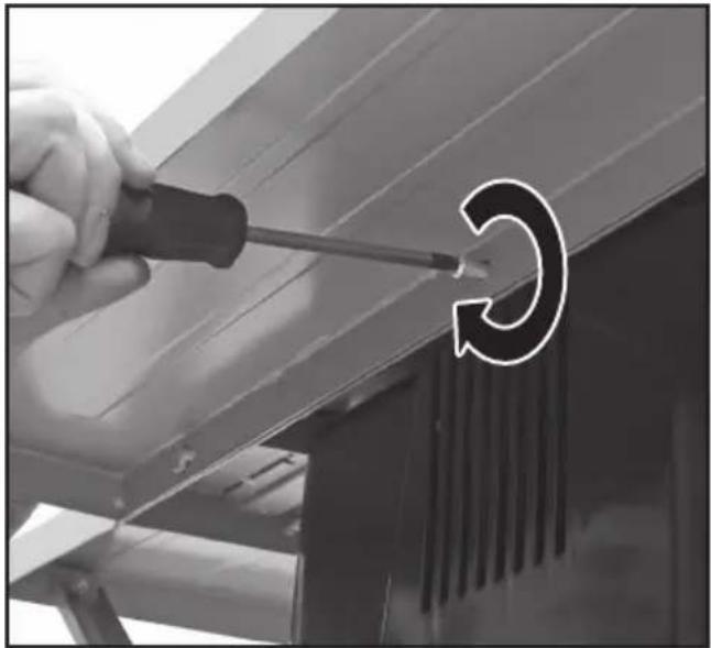
Fig. F1 - F4
- Before attaching the bench extensions, first remove the perforated base plate (you can now also remove and discard the motor protection materials).
- Once the bottom side is open, you can attach the diagonal support struts to the bench saw.
- Now attach the bench extensions to
the basic bench top. Next, attach the extensions to the diagonal support struts.
- Once all the extensions have been assembled, re-attach the base plate (taking care that all extensions are perfectly lined up with the basic bench top itself).
- Lastly, attach the guide rail (with ruler) to the front edge of the bench top.
Assembly of the stand
Fig. G1 + G2
Use the included nuts (13) to attach the rubber feet (12) to the support foot (15).
Insert the support foot into the stand (16) and tighten with the included nuts and bolts.
Adjusting the working height
The stand can be set to 2 different height positions.
• Make sure the brake (11) is off.
- Support the support foot and pull the height adjustment handle (9). Pull the table up by pulling the handgrip (10) towards you. Set the stand to the right height position. Release the height adjustment handle and make sure the locking bolt locks into place.
- To lower the stand take the brake off. Pull the height adjustment handle. Support the support foot and push the handgrip. When the stand reaches the right height, release the height adjustment handle and make sure the locking bolt locks into position.
Mounting the saw table to the stand
Bolt the saw table to the support bars on the stand. Make sure the nuts and bolts are fixed secure and tight. Check the bolts and nuts before switching the machine on.
Assembly of the bench saw on the workbench
Fig. B & C

Before adjusting the saw, make sure the plug is removed from the socket.
Fig. B shows the distance of the holes to be drilled in the workbench on which to fasten the machine. Drill holes of 8 mm.

Only use the machine after it has been assembled completely and it has been screwed onto the workbench or the stand.
- Fig. C shows the part to be sawn out (310 x 310 mm), so that the sawdust can fall through it and piling up is prevented!
Only if you do not use an extraction system!
- Fasten the machine with bolts.
When using the base, the same must be fixed to the ground using four bolts. The saw in turn must be fixed to the base with four bolts. Check these bolts for tightness before switching on the machine.
Assembly and attachment of the rip fence Fig. D1 + D2
- Attach the aluminium fence (A) to the positioning block (B).
- Now you can attach the complete rip fence to the bench top.
- Slide the rip fence via one end of the positioning rail (C) over the bench top.
- Adjust the position of the aluminium fence profile (A) such that the end corresponds to the rear edge of the saw.
Assembly of the riving knife and the protective cap
Fig. E1 - E3
- Turn the saw blade completely upwards.
- Remove the bench inlay.
- Assemble the riving knife on the set-up for this purpose and use hereby the Allen screws and the filling rings. Ensure that the riving knife falls properly into the opening (= groove).
- Now put the inlay back in the bench and fasten it.
- Now assembly the protective cap onto the riving knife and use hereby the profiled nut and self-locking nut.

Now lay a lath against the saw blade and the riving knife and check whether it falls properly into the extension of the saw blade. If this is not the case: Loosen the fastening bolts and place or remove the filling rings.
- Above the saw table the radial distance between the riving knife and the toothed rim of the saw blade shall not at any point exceed 5 mm at the depth of cut set.
- The tip of the riving knife shall not be lower than 5 mm from the tooth peak, as shown.
Assembly of the saw blade

First remove the plug from the mains before the saw blade is assembled or replaced.
- Remove the inlay from the bench. Use a screwdriver for this purpose.
- Turn the saw axle completely upwards. Remove the nut and the outside flange from the saw axle.
- Now slide the saw blade over the saw axle and now put the outside flange and the nut back. Tighten the nut by hand.
- Now use the 2 keys: one for the flange and one for the nut and now clamp it.
- Now put the inlay back in the bench and fasten it.
Mounting the push stick holders
Fig. F2 - F4
Mount both push stick holders on the side of the machine using the bolts and rings supplied.
Use of the mitring set-up
Fig. A
By turning the handle at the side of the machine you can adjust the saw blade to a maximum of 45^ (4).
4. OPERATION
Working instructions
There are two types of sawing methods:
• Lengthwise sawing
Sawing the workpiece in the length of the wood grain.
• Cross-cutting or cutting off
Sawing off the workpiece crosswise.
If it concerns a panel, we do not usually distinguish between the wood grain, but we name the method where we saw off a part of the width of the panel (lengthwise sawing) and when we cut off the length (cross-cutting or cutting-off).

For both sawing methods one of the fences must be used. Therefore never saw without a fence!
Attention! Before you start sawing, first check the following:
-
Is the saw blade secured?
-
Are all the locking handles secured?
- Is the fence parallel to the saw blade?
- Is the protective cap working properly?
- Are you wearing safety goggles?
- Is the saw blade not rubbing against anything?

It is absolutely necessary to take these points into consideration before you start work!
Lengthwise sawing
- Secure the fence to the correct measuring position and remove the cut-off guide from the bench carriage.
- Turn the saw blade approximately 2 mm higher than the total thickness of the wood to be sawn.
- Press the wood lightly towards the bench and let it glide against the cut-off fence.

Remain at least 3 cm. from the front of the saw blade before you switch on the engine. The side of the wood which is against the fence must be completely straight. Keep your hands at least 10 cm away from the saw track to be followed.
- Switch on the engine and wait until the saw blade has reached the maximum number of revolutions before you start sawing.
- While you press the wood against the bench and the fence, you can carefully push the wood through the saw blade without forcing it.
- Never pull the workpiece backwards. If necessary, switch off the engine first without altering the position of the workpiece.
Lengthwise sawing with a(vertical) mitre
This method is practically the same, except that the saw blade is placed at the angle required.

With this type of method the fence may only be along the righthand side of the sawblade.
Lengthwise sawing of narrow workpieces

Assume that this process is extremely dangerous.
Take all the necessary safety measures and continually push the workpiece through (until behind the saw blade) using a synthetic aid instead of by hand.
Crosswise sawing
- Remove the fence and apply the cross-cut fence in the righthand carriage.
- Adjust the height of the saw blade (see lengthwise sawing).
- Press the workpiece against the cross-cut fence and keep at least 2,5 cm distance from the front of the saw blade.
- Switch on the engine and wait until the maximum number of revolutions has been reached.
- Press the workpiece against the fence and the bench. Carefully push the wood through the saw blade. Continue until behind the saw blade. Then switch off the engine and keep this position until the saw blade has stopped completely before you remove the wood.
- Never pull the wood back. If necessary, switch the engine off and keep the position until the saw blade has stopped completely.
Crosswise sawing with a vertical mitre
This method is practically the same, except that the saw blade is placed in the angle required.

Only place the cross-cut fence on the righthand side of the saw blade. Never saw too small pieces of wood. Never use your hands to carry out difficult operations.
Crosswise sawing with a horizontal mitre
With this method the cross-cut fence must be secured at the angle required. Keep the workpiece pressed firmly against the cross-cut fence and the bench before you start cutting off.
5. MAINTENANCE

Make sure that the machine is not live when carrying out maintenance work on the motor.
The machines have been designed to operate over a long period of time with a minimum of maintenance. Continuous satisfactory operation depends upon proper machine care and regular cleaning.
Malfunctions
In the case that the machine is not functioning properly, we give a number of possible causes and appropriate solutions below.
1. The engine does not start
• The plug is not in the mains.
• The cable has been interrupted.
2. The workpieces is jamming against the riving knife during processing
• The saw blade must be aligned (Fig. E).
3. The saw cut is not smooth (frayed)
• The saw blade must be sharpened.
- The saw blade has been assembled back-to-front.
- The saw blade has become coated with resin or sawdust.
- The saw blade is not suitable for this process.
4. The workpiece is touching the back of the saw blade and is jumping out
• The riving knife must be aligned (Fig. E).
• The fence is not being used.
- The saw blade is thicker than the riving knife or the riving knife is not being used
• The saw blade must be sharpened.
- The workpiece has not been kept in its place until after sawing.
- The tension button of the cross-cut fence is loose.
5. The height and/or mitre handle is blocked
- Sawdust and dust must be removed.
6. The engine has difficulty reaching the maximum number of revolutions
- The extension cable is too thin and/or too long.
• The mains voltage is lower than 230 V.
7. The machine is vibrating
- The machine has not been fastened onto the workbench.
• The frame is not level with the floor.
• The saw blade has been damaged.
Cleaning
Keep the ventilation slots of the machine clean to prevent overheating of the engine. Regularly clean the machine housing with a soft cloth, preferably after each use. Keep the ventilation
slots free from dust and dirt. If the dirt does not come off use a soft cloth moistened with soapy water. Never use solvents such as petrol, alcohol, ammonia water, etc. These solvents may damage the plastic parts.
Lubrication
The machine requires no additional lubrication.
Faults
Should a fault occur, e.g. after wear of a part, please contact your local Ferm dealer. In the back of this manual you find an exploded view showing the parts that can be ordered.
Environment
To prevent damage during transport, the appliance is delivered in a solid packaging which consists largely of reusable material. Therefore please make use of options for recycling the packaging.

Faulty and/or discarded electrical or electronic apparatus have to be collected at the appropriate recycling locations.
Warranty
The warranty conditions can be found on the separately enclosed warranty card.
TISCHKREISSÄGE

Suction mouth 30 (20) mm
Gewicht 37 kg
It is absolutely necessary to take these points into consideration before you start work!
DECLARATION OF CONFORMITY FZT-250/1500 Table Saw
(GB) We declare under our sole responsibility that this product is in conformity and accordance with the following standards and regulations:
Quality Manager Ferm Global
It is our policy to continuously improve our products and we therefore reserve the right to change the product specification without prior notice.
Ferm BV • Lingenstraat 6 • 8028 PM • Zwolle The Netherlands
Spare parts list
| Postion | Description | No. | |
| 407870 | Guard complete | 1, 2, 4, 5, 6, 7 (6x) | |
| 407963 | Riving knife | 3 | |
| 407872 | Angle guide complete | 13 till 17 | |
| 407964 | Inlay | 35 | |
| 407965 | Bench extensions complete | 25, 26, 38, 22 (2x), 27 (4x) | |
| 407966 | Rip fence | 39 till 41 | |
| 407967 | Positioning block | 42 till 57 + 12 | |
| 407498 | Motor (with brake) | 77 | |
| 407968 | Flange set complete | 58, 59, 61 | |
| TSA1001 | Saw blade FZT-250, wood | 60 | |
| 407475 | Dust-exhaust connection | 105 | |
| 407497 | Thermal switch (7A) | 99, 119, 120 | |
| 407496 | Switch (with brake) | 121 | |
| 407882 | Holder for stick | 2x (23, 24, 97), 107 | |
| 407969 | Floorstand complete | 19 till 21, 127 till 130 | |
| 407970 | Screw set for stand | 19 till 21, 130 | |
| 407971 | Rubber foot for stand | 127 | |
| 407469 | Carbon brush (set) | 135 | |
| 407980 | Tighten knob | 118 | |
Exploded view A

Exploded view B

GB Subject to change
- TABLE SAW
- Contents
- TECHNICAL SPECIFICATIONS
- Product information
- Fig. A
- SAFETY INSTRUCTIONS
- Explanation of symbols
- Device-specific safety information Safety measures
- Maintenance and service
- Safe operation
- Further important information
- Electrical safety
- Replacing cables or plugs
- Using extension cables
- ASSEMBLY INSTRUCTIONS
- Assembly of the bench extensions
- Fig. F1 - F4
- Assembly of the stand
- Fig. G1 + G2
- Adjusting the working height
- Mounting the saw table to the stand
- Assembly of the bench saw on the workbench
- Assembly and attachment of the rip fence Fig. D1 + D2
- Assembly of the riving knife and the protective cap
- Fig. E1 - E3
- Assembly of the saw blade
- Mounting the push stick holders
- Fig. F2 - F4
- Use of the mitring set-up
- OPERATION
- Working instructions
- Lengthwise sawing
- Lengthwise sawing with a(vertical) mitre
- Lengthwise sawing of narrow workpieces
- Crosswise sawing
- Crosswise sawing with a vertical mitre
- Crosswise sawing with a horizontal mitre
- MAINTENANCE
- Malfunctions
- The engine does not start
- The workpieces is jamming against the riving knife during processing
- The saw cut is not smooth (frayed)
- The workpiece is touching the back of the saw blade and is jumping out
- The height and/or mitre handle is blocked
- The engine has difficulty reaching the maximum number of revolutions
- The machine is vibrating
- Cleaning
- Lubrication
- Faults
- Environment
- Warranty
- TISCHKREISSÄGE
- DECLARATION OF CONFORMITY FZT-250/1500 Table Saw
- Exploded view A
Brand : Ferm
Model : FZT-250/1500
Category : Jigsaw