
G 13YC - Grinder HITACHI - Free user manual and instructions
Find the device manual for free G 13YC HITACHI in PDF.

| Product Type | Angle Grinder |
| Brand | Hitachi |
| Model | G 13YC |
| Power Input | 1500 W |
| No-Load Speed | 10000 min-1 |
| Wheel Diameter | 125 mm |
| Hole Diameter | 22 mm |
| Peripheral Speed | 80 m/s |
| Weight (Main Body) | 2.0 kg |
| Voltage | 110V or 230V (check nameplate) |
| Speed Control | Electronic constant speed |
| Overload Protection | Yes (current limiting) |
| Soft-Start | Yes |
| Switch Type | Paddle switch with lock mechanism (on some models) |
| Wheel Guard | Adjustable, secured with screw |
| Side Handle | Included, screws into gear cover |
| Spindle Lock | Yes (push button) |
| Carbon Brushes | Replaceable, wear limit indicator |
| Noise Level | Sound power 95 dB(A), sound pressure 84 dB(A) |
| Vibration | 2.5 m/s2 |
| Standard Accessories | Depressed center wheel (1), wrench (1), side handle (1) |
| Applications | Grinding and cutting metal, concrete, stone, brick, marble, synthetic resins |
Frequently Asked Questions - G 13YC HITACHI
User questions about G 13YC HITACHI
0 question about this device. Answer the ones you know or ask your own.
Ask a new question about this device
Download the instructions for your Grinder in PDF format for free! Find your manual G 13YC - HITACHI and take your electronic device back in hand. On this page are published all the documents necessary for the use of your device. G 13YC by HITACHI.
USER MANUAL G 13YC HITACHI
natural_image
Line drawing of a power tool with a grinding wheel and blade, labeled G 15YC (no other text or symbols)Read through carefully and understand these instructions before use.

Bruksanvisning
Brugsanvisning
Bruksanvisning
Käyttöohjeet
Handling Instructions
Hitachi Koki
1
[G 13YC] [G 15YC]
2
[G 15YC]
3
4
(a)
(b) ⑮
natural_image
Diagram of a mechanical component with an arrow indicating direction (no text or symbols present)5
6
| Svenska Dansk Norsk | |||
| 1 | Nyckel Nøgle Nøkkel | ||
| 2 | Skivmutter Møtrik il slibeskive Mutter til slipeskiven | ||
| 3 | Tillbehön slipskiva Nedtrykket centerskive Skive med senket nav | ||
| 4 | Mellanlägg Spændeskive Underlagskive til slipeskive | ||
| 5 | Sprängskydd Beskyttelseskappe Vernedeksel | ||
| 6 | Spindel Slibespindel Spindel | ||
| 7 | Tryckknapp Trykknap Trykknapp | ||
| 8 | Diamanthjul Diamantskive Diamanthjul | ||
| 9 | M5-skruv | M5 skrue M5-skrue | |
| 10 | Spak | Arm | Hendel |
| 11 | Ställdel (B) Indstillings-del (B) | Stillestykke (B) | |
| 12 | Bakstycke | Pinoldæksel | Haledeksel |
| 13 | Spärrspak | Skovlarm | Padlespak |
| 14 | Låsspak | Låsearm | Låsespak |
| 15 | Strömbrytare med låsmekanism | Afbryder med låsemekanisme | Bryter med låsemekanisme |
| 16 | Avnötningsgräns | Slidgrænse | Slitasjegrense |
| 17 | Nr. av kolsborste | Kulnummer | Kullbørstens Nr. |
| 18 | Fjäder | Fjader | Fjær |
| 19 | Kolbørste | Kullbørste | Kullbørste |
| 20 | Kolhållare | Kulholder | Børsteholder |
VEDLIKEHOLD OG INSPEKSJON
Read all safety warnings and all instructions.
Failure to follow the warnings and instructions may result in electric shock, fire and/or serious injury.
Save all warnings and instructions for future reference.
The term "power tool" in the warnings refers to your mains-operated (corded) power tool or battery-operated (cordless) power tool.
1) Work area safety
a) Keep work area clean and well lit.
Cluttered or dark areas invite accidents.
b) Do not operate power tools in explosive atmospheres, such as in the presence of flammable liquids, gases or dust.
Power tools create sparks which may ignite the dust or fumes.
c) Keep children and bystanders away while operating a power tool.
Distractions can cause you to lose control.
2) Electrical safety
a) Power tool plugs must match the outlet.
Never modify the plug in any way.
Do not use any adapter plugs with earthed (grounded) power tools.
Unmodified plugs and matching outlets will reduce risk of electric shock.
b) Avoid body contact with earthed or grounded surfaces, such as pipes, radiators, ranges and refrigerators.
There is an increased risk of electric shock if your body is earthed or grounded.
c) Do not expose power tools to rain or wet conditions.
Water entering a power tool will increase the risk of electric shock.
d) Do not abuse the cord. Never use the cord for carrying, pulling or unplugging the power tool.
Keep cord away from heat, oil, sharp edges or moving parts.
Damaged or entangled cords increase the risk of electric shock.
e) When operating a power tool outdoors, use an extension cord suitable for outdoor use.
Use of a cord suitable for outdoor use reduces the risk of electric shock.
f) If operating a power tool in a damp location is unavoidable, use a residual current device (RCD) protected supply.
Use of an RCD reduces the risk of electric shock.
3) Personal safety
a) Stay alert, watch what you are doing and use common sense when operating a power tool.
Do not use a power tool while you are tired or under the influence of drugs, alcohol or medication.
A moment of inattention while operating power tools may result in serious personal injury.
b) Use personal protective equipment. Always wear eye protection.
Protective equipment such as dust mask, non-skid safety shoes, hard hat, or hearing protection used for appropriate conditions will reduce personal injuries.
c) Prevent unintentional starting. Ensure the switch is in the off-position before connecting to power source and/or battery pack, picking up or carrying the tool.
Carrying power tools with your finger on the switch or energising power tools that have the switch on invites accidents.
d) Remove any adjusting key or wrench before turning the power tool on.
A wrench or a key left attached to a rotating part of the power tool may result in personal injury.
e) Do not overreach. Keep proper footing and balance at all times.
This enables better control of the power tool in unexpected situations.
f) Dress properly. Do not wear loose clothing or jewellery. Keep your hair, clothing and gloves away from moving parts.
Loose clothes, jewellery or long hair can be caught in moving parts.
g) If devices are provided for the connection of dust extraction and collection facilities, ensure these are connected and properly used.
Use of dust collection can reduce dust related hazards.
4) Power tool use and care
a) Do not force the power tool. Use the correct power tool for your application.
The correct power tool will do the job better and safer at the rate for which it was designed.
b) Do not use the power tool if the switch does not turn it on and off.
Any power tool that cannot be controlled with the switch is dangerous and must be repaired.
c) Disconnect the plug from the power source and/or the battery pack from the power tool before making any adjustments, changing accessories, or storing power tools.
Such preventive safety measures reduce the risk of starting the power tool accidentally.
d) Store idle power tools out of the reach of children and do not allow persons unfamiliar with the power tool or these instructions to operate the power tool.
Power tools are dangerous in the hands of untrained users.
e) Maintain power tools. Check for misalignment or binding of moving parts, breakage of parts and any other condition that may affect the power tool's operation.
If damaged, have the power tool repaired before use. Many accidents are caused by poorly maintained power tools.
f) Keep cutting tools sharp and clean.
Properly maintained cutting tools with sharp cutting edges are less likely to bind and are easier to control.
g) Use the power tool, accessories and tool bits etc. in accordance with these instructions, taking into account the working conditions and the work to be performed.
Use of the power tool for operations different from those intended could result in a hazardous situation.
5) Service
a) Have your power tool serviced by a qualified repair person using only identical replacement parts.
This will ensure that the safety of the power tool is maintained.
PRECAUTION
Keep children and infirm persons away.
When not in use, tools should be stored out of reach of children and infirm persons.
SAFETY WARNINGS COMMON FOR GRINDING OR ABRASIVE CUTTING-OFF OPERATIONS
a) This power tool is intended to function as a grinder or cut-off tool. Read all safety warnings, instructions, illustrations and specifications provided with this power tool.
Failure to follow all instructions listed below may result in electric shock, fire and/or serious injury.
b) Operations such as sanding, wire brushing or polishing are not recommended to be performed with this power tool.
Operations for which the power tool was not designed may create a hazard and cause personal injury.
c) Do not use accessories which are not specifically designed and recommended by the tool manufacturer.
Just because the accessory can be attached to your power tool, it does not assure safe operation.
d) The rated speed of the accessory must be at least equal to the maximum speed marked on the power tool.
Accessories running faster than their rated speed can break and fly apart.
e) The outside diameter and the thickness of your accessory must be within the capacity rating of your power tool.
Incorrectly sized accessories cannot be adequately guarded or controlled.
f) The arbour size of wheels, flanges, backing pads or any other accessory must properly fit the spindle of the power tool.
Accessories with arbour holes that do not match the mounting hardware of the power tool will run out of balance, vibrate excessively and may cause loss of control.
g) Do not use a damaged accessory. Before each use inspect the accessory such as abrasive wheels for chips and cracks, backing pad for cracks, tear or excess wear, wire brush for loose or cracked wires. If power tool or accessory is dropped, inspect for damage or install an undamaged accessory. After inspecting and installing an accessory, position yourself and bystanders away from the plane of the rotating accessory and run the power tool at maximum no-load speed for one minute.
Damaged accessories will normally break apart during this test time.
h) Wear personal protective equipment. Depending on application, use face shield, safety goggles or safety glasses. As appropriate, wear dust mask, hearing protectors, gloves and workshop apron capable of stopping small abrasive or workpiece fragments.
The eye protection must be capable of stopping flying debris generated by various operations. The dust mask or respirator must be capable of filtrating particles generated by your operation. Prolonged exposure to high intensity noise may cause hearing loss.
i) Keep bystanders a safe distance away from work area. Anyone entering the work area must wear personal protective equipment.
Fragments of workpiece or of a broken accessory may fly away and cause injury beyond immediate area of operation.
j) Hold power tool by insulated gripping surfaces only, when performing an operation where the cutting accessory may contact hidden wiring or its own cord.
Cutting accessory contacting a "live" wire may make exposed metal parts of the power tool "live" and shock the operator.
k) Position the cord clear of the spinning accessory. If you lose control, the cord may be cut or snagged and your hand or arm may be pulled into the spinning accessory.
I) Never lay the power tool down until the accessory has come to a complete stop.
The spinning accessory may grab the surface and pull the power tool out of your control.
m) Do not run the power tool while carrying it at your side.
Accidental contact with the spinning accessory could snag your clothing, pulling the accessory into your body.
n) Regularly clean the power tool's air vents.
The motor's fan will draw the dust inside the housing and excessive accumulation of powdered metal may cause electrical hazards.
o) Do not operate the power tool near flammable materials.
Sparks could ignite these materials.
p) Do not use accessories that require liquid coolants.
Using water or other liquid coolants may result in electrocution or shock.
KICKBACK AND RELATED WARNINGS
Kickback is a sudden reaction to a pinched or snagged rotating wheel, backing pad, brush or any other accessory. Pinching or snagging causes rapid stalling of the rotating accessory which in turn causes the uncontrolled power tool to be forced in the direction opposite of the accessory's rotation at the point of the binding.
For example, if an abrasive wheel is snagged or pinched by the workpiece, the edge of the wheel that is entering into the pinch point can dig into the surface of the material causing the wheel to climb out or kick out. The wheel may either jump toward or away from the operator, depending on direction of the wheel's movement at the point of pinching. Abrasive wheels may also break under these conditions.
Kickback is the result of power tool misuse and/or incorrect operating procedures or conditions and can be avoided by taking proper precautions as given below.
a) Maintain a firm grip on the power tool and position your body and arm to allow you to resist kickback forces. Always use auxiliary handle, if provided, for maximum control over kickback or torque reaction during start-up.
The operator can control torque reactions or kickback forces, if proper precautions are taken.
b) Never place your hand near the rotating accessory. Accessory may kickback over your hand.
c) Do not position your body in the area where power tool will move if kickback occurs.
Kickback will propel the tool in direction opposite to the wheel's movement at the point of snagging.
d) Use special care when working corners, sharp edges etc. Avoid bouncing and snagging the accessory. Corners, sharp edges or bouncing have a tendency to snag the rotating accessory and cause loss of control or kickback.
e) Do not attach a saw chain woodcarving blade or toothed saw blade.
Such blades create frequent kickback and loss of control.
SAFETY WARNINGS SPECIFIC FOR GRINDING AND ABRASIVE CUTTING-OFF OPERATIONS
a) Use only wheel types that are recommended for your power tool and the specific guard designed for the selected wheel.
Wheels for which the power tool was not designed cannot be adequately guarded and are unsafe.
b) The guard must be securely attached to the power tool and positioned for maximum safety, so the least amount of wheel is exposed towards the operator.
The guard helps to protect operator from broken wheel fragments and accidental contact with wheel.
c) Wheels must be used only for recommended applications. For example: do not grind with the side of cut-off wheel.
Abrasive cut-off wheels are intended for peripheral grinding, side forces applied to these wheels may cause them to shatter.
d) Always use undamaged wheel flanges that are of correct size and shape for your selected wheel.
Proper wheel flanges support the wheel thus reducing the possibility of wheel breakage. Flanges for cut-off wheels may be different from grinding wheel flanges.
e) Do not use worn down wheels from larger power tools.
Wheel intended for larger power tool is not suitable for the higher speed of a smaller tool and may burst.
ADDITIONAL SAFETY WARNINGS SPECIFIC FOR ABRASIVE CUTTING-OFF OPERATIONS
a) Do not "jam" the cut-off wheel or apply excessive pressure. Do not attempt to make an excessive depth of cut.
Overstressing the wheel increases the loading and susceptibility to twisting or blinding of the wheel in the cut and the possibility of kickback or wheel breakage.
b) Do not position your body in line with and behind the rotating wheel.
When the wheel, at the point of operation, is moving away from your body, the possible kickback may propel the spinning wheel and the power tool directly at you.
c) When wheel is binding or when interrupting a cut for any reason, switch off the power tool and hold the power tool motionless until the wheel comes to a complete stop. Never attempt to remove the cut-off wheel from the cut while the wheel is in motion otherwise kickback may occur.
Investigate and take corrective action to eliminate the cause of wheel binding.
d) Do not restart the cutting operation in the workpiece. Let the wheel reach full speed and carefully reenter the cut.
The wheel may bind, walk up or kickback if the power tool is restarted in the workpiece.
e) Support panels or any oversized workpiece to minimize the risk of wheel pinching and kickback. Large workpieces tend to sag under their own weight. Supports must be placed under the workpiece near the line of cut and near the edge of the workpiece on both sides of the wheel.
f) Use extra caution when making a "pocket cut" into existing walls or other blind areas.
The protruding wheel may cut gas or water pipes, electrical wiring or objects that can cause kickback.
PRECAUTIONS ON USING DISC GRINDER
- Never operate these power tools without Wheel Guards.
- Check that speed marked on the wheel is equal to or greater than the rated speed of the grinder. Use only depressed center wheels rated at 80m/s or more.
- Always hold the body handle and side handle of the power tool firmly. Otherwise the counterforce produced may result in inaccurate and even dangerous operation.
- Never depress the push button while the spinble is turning.
- Do not work near welding equipment! If you work near welding equipment, rotation may become unstable.
- Overload protection circuit operation. If an overload or abnormal load is applied, the overload protection circuit operates and stops rotation, so please immediately stop applying load. Following this, switching the power OFF and then ON again, will cause the rotation to increase to the regular speed.
SPECIFICATIONS
| Model G13YC G15YC | |||
| Voltage (by areas)* (110V, 230V) | ~ | ||
| Power Input* 1500 W | |||
| No-load speed 10000 min | -1 | 8500 min^-1 | |
| Wheel | Outer dia. × hole dia. | 125 × 22 mm | 150 × 22 mm |
| Peripheral speed 80 m/s | |||
| Weight (Only main body) 2.0 kg | |||
*Be sure to check the nameplate on product as it is subject to change by areas.
Constant Electronic
The grinder has an electronic speed control which provides:
○ full speed at all times in the range up to rated load.
○ overload protection when exceeding the rated load due to current limiting. The grinder then stalls and restarts when the grinding pressure is reduced.
○ soft-start.
STANDARD ACCESSORIES
(1) Depressed center wheel 1
(2) Wrench .... 1
(3) Side handle 1
Standard accessories are subject to change without notice.
APPLICATIONS
○ Removal of casting fin and finishing of various types of steel, bronze and aluminum materials and castings.
○Grinding of welded sections or sections cut by means of a cutting torch.
○Grinding of synthetic resins, slate, brick, marble, etc.
○Cutting of synthetic concrete, stone, brick, marble, and similar materials.
PRIOR TO OPERATION
1. Power source
Ensure that the power source to be utilized conforms to the power requirements specified on the product nameplate.
CAUTION:
Do not operate on Direct Current power source.
2. Power switch
Ensure that the power switch is in the OFF position. If the plug is connected to a receptacle while the power switch is in the ON position, the power tool will start operating immediately, which could cause a serious accident.
3. Extension cord
When the work area is removed from the power source, use an extension cord of sufficient thickness and rated capacity. The extension cord should be kept as short as practicable.
4. Fitting and adjusting the wheel guard
The wheel guard is a protective device to prevent injury should the depressed center wheel shatter during operation. Ensure that the guard is properly fitted and fastened before commencing grinding operation.
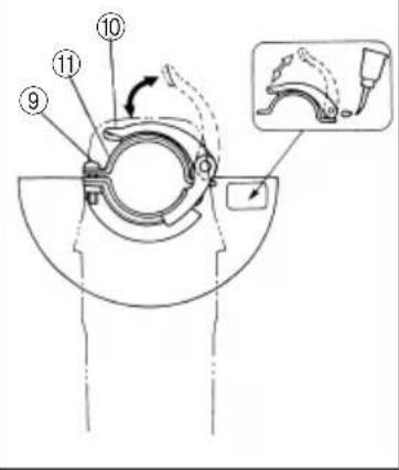
[How to attach and adjust the wheel guard] (G13YC)
By slightly loosening the setting screw, the wheel guard can be turned and set at any desired angle for maximum operational effectiveness. Ensure that the setting screw is thoroughly tightened after adjusting the wheel guard.
〈G15YC〉(Fig. 2)
○ Set the wheel ass'y to the packing gland.
○ Tighten M5 screw to secure the wheel guard while the lever is in closed position.
○ Perform the adjustment of the wheel guard while the adjustment of the wheel guard while the lever is released. (Loosen M5 screw and readjust if the wheel guard does not rotate smoothly.)
○ After adjustment, if machine operation is required, perform the operation only after setting the lever in closed position.
○ Lubricate the sliding section of the set piece (B) and the lever if the lever does not move smoothly.
- Ensure that the depressed center wheel to be utilized is the correct type and free of cracks or surface defects. Also ensure that the depressed center wheel is properly mounted and the wheel nut is securely tightened. Refer to the section on "ASSEMBLING AND DISASSEMBLING THE DEPRESSED CENTER WHEEL".
6. Conducting a trial run
Ensure that the abrasive products is correctly mounted and tightened before use and run the tool at no-load for 30 seconds in a safe position, stop immediately if there is considerable vibration or if other defects are detected. If this condition occurs, check the machine to determine the cause.
7. Confirm the spindle lock mechanism.
Confirm that the spindle lock is disengaged by pushing push button two or three times before switching the power tool on (See Fig. 1).
8. Fixing the side handle
Screw the side handle into the gear cover.
PRACTICAL GRINDER APPLICATION
1. Grinding Pressure
Do not apply the depressed center wheel strongly to the grinding surface. The grinder makes use of electronic circuit, so during application of load rotates at high speed, so ample grinding effect can be obtained by applying light pressure. If a strong grinding pressure or other abnormal load is applied, the overload protection circuit will operate and make the grinder stop rotating, so please stop applying load immediately. Following this, switching the power OFF and then ON again, will cause the rotation to increase to the regular speed.
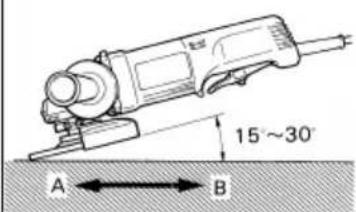
2. Grinding angle
Do not apply the entire surface of the depressed center wheel to the material to be ground. As shown in Fig. 3, the machine should be held at an angle of 15^ - 30^ so that the external edge of the depressed center wheel contacts the material at an optimum angle.
- To prevent a new depressed center wheel from digging into the workpiece, initial grinding should be performed by drawing the grinder across the workpiece toward the operator (Fig. 3 direction B). Once the leading edge of the depressed center wheel is properly abraded, grinding may be conducted in either direction.
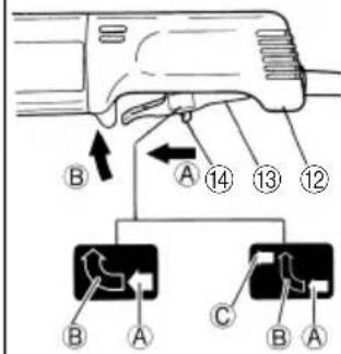
4. Switch operation
[When the switch has locking mechanism]
Switch ON: To switch on, slide the lock lever in the direction of Ⓐ and press the paddle lever in the direction of Ⓑ as shown in Fig. 4-a.
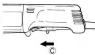
Furthermore, slide the lock lever in the direction of © shown in Fig. 4-b while pressing the paddle lever to lock and enable continuous operation.
Switch OFF: To release the locking mode, press the paddle lever in the direction of ⑧ shown in Fig. 4-a, and release the paddle lever to switch off.
[When the switch has no locking mechanism]
To switch on, slide the lock lever in the direction of Ⓐ and press the paddle lever in the direction of Ⓑ as shown in Fig. 4-a. Release the paddle lever to switch off.
NOTE: The paddle lever can not be locked.
- Precautions immediately after finishing operation The wheel continues to rotate after the tool is switched off.
After switching off the machine, do not put it down until the depressed center wheel has come to a complete stop. Apart from avoiding serious accidents, this precaution will reduce the amount of dust and swarf sucked into the machine.
CAUTIONS
○Check that the work piece is properly supported.
○Ensure that ventilation openings are kept clear when working in dusty conditions.
If it should become necessary to clear dust, first disconnect the tool from the mains supply (use non-metallic objects) and avoid damaging internal parts.
○Ensure that sparks resulting from use do not create a hazard e.g. do not hit persons, or ignite flammable substances.
○Always use protective safety glasses and hearing protectors, use other personal protective equipment such as gloves, apron and helmet when necessary.
○Always use eye and ear protection.
Other personal protective equipment such as dust mask, gloves, helmet and apron should be worn when necessary.
If in doubt, wear the protective equipment.
When the machine is not use, the power source should be disconnected.
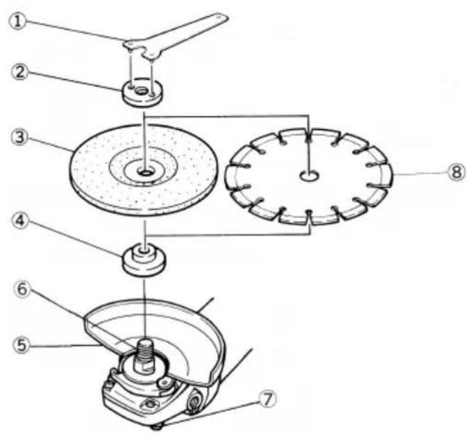
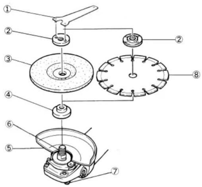
ASSEMBLING AND DISASSEMBLING THE DEPRESSED CENTER WHEEL (Fig. 1)
CAUTION Be sure to switch OFF and disconnect the attachment plug from the receptacle to avoid a serious accident.
1. Assembling (Fig. 1)
(1) Turn the grinder upsidedown so that the spindle is facing upward.
(2) Mount the wheel washer onto the spindle.
(3) Fit the protuberance of the depressed center wheel or diamond wheel onto the wheel washer.
(4) Assemble the wheel nut onto the spindle. (With G15YC, for diamond wheel assembling, use the wheel nut with the flat side against the diamond wheel.)
(5) Insert the push button to prevent rotation of the spindle, and tighten the wheel nut with accessory wrench, as shown in Fig. 1.
2. Disassembling
Follow the above procedures in reverse.
CAUTIONS
○Comfirm that the depressed center wheel is mounted firmly.
○Confirm that the spindle lock mechanism is disengaged by pushing push button two or three times before switching the grinder on.
MAINTENANCE AND INSPECTION
- Inspecting the depressed center wheel
Ensure that the depressed center wheel is free of cracks and surface defects.
- Inspecting the mounting screws
Regularly inspect all mounting screws and ensure that they are properly tightened. Should any of the screws be loose, retighten them immediately. Failure to do so could result in serious hazard.
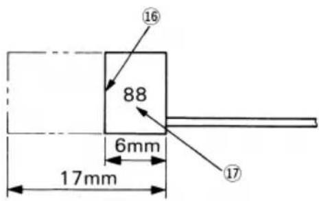
- Inspecting the carbon brushes (Fig. 5)
The motor employs carbon brushes which are consumable parts. Since an excessively worn carbon brush can result in motor trouble, replace the carbon brushes with new ones having the same carbon brush No. shown in the figure when it becomes worn to or near the "wear limit". In addition, always keep carbon brushes clean and ensue that they slide freely within the brush holders.
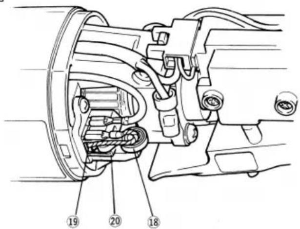
4. Replacing carbon brushes (Fig. 6)
(1) Loosen the D4 tapping screw retaining the tail cover and remove the tail cover.
(2) Use the auxiliary hexagonal wrench or small screwdriver to pull up the edge of the spring that is holding down the carbon brush. Remove the edge of the spring toward the outside of the brush holder. 32
(3) Remove the end of the pig-tail on the carbon brush from the terminal section of brush holder and then remove the carbon brush form the brush holder.
(1) Insert the end of the pig-tail of the carbon brush in the terminal section of brush holder.
(2) Insert the carbon brush in the brush holder.
(3) Use the auxiliary hexagonal wrench or small screwdriver to return the edge of the spring to the head of the carbon brush.
(4) Mount the tail cover and tighten the D4 tapping screw.
5. Maintenance of the motor
The motor unit winding is the very "heart" of the power tool. Exercise due care to ensure the winding does not become damaged and/or wet with oil or water.
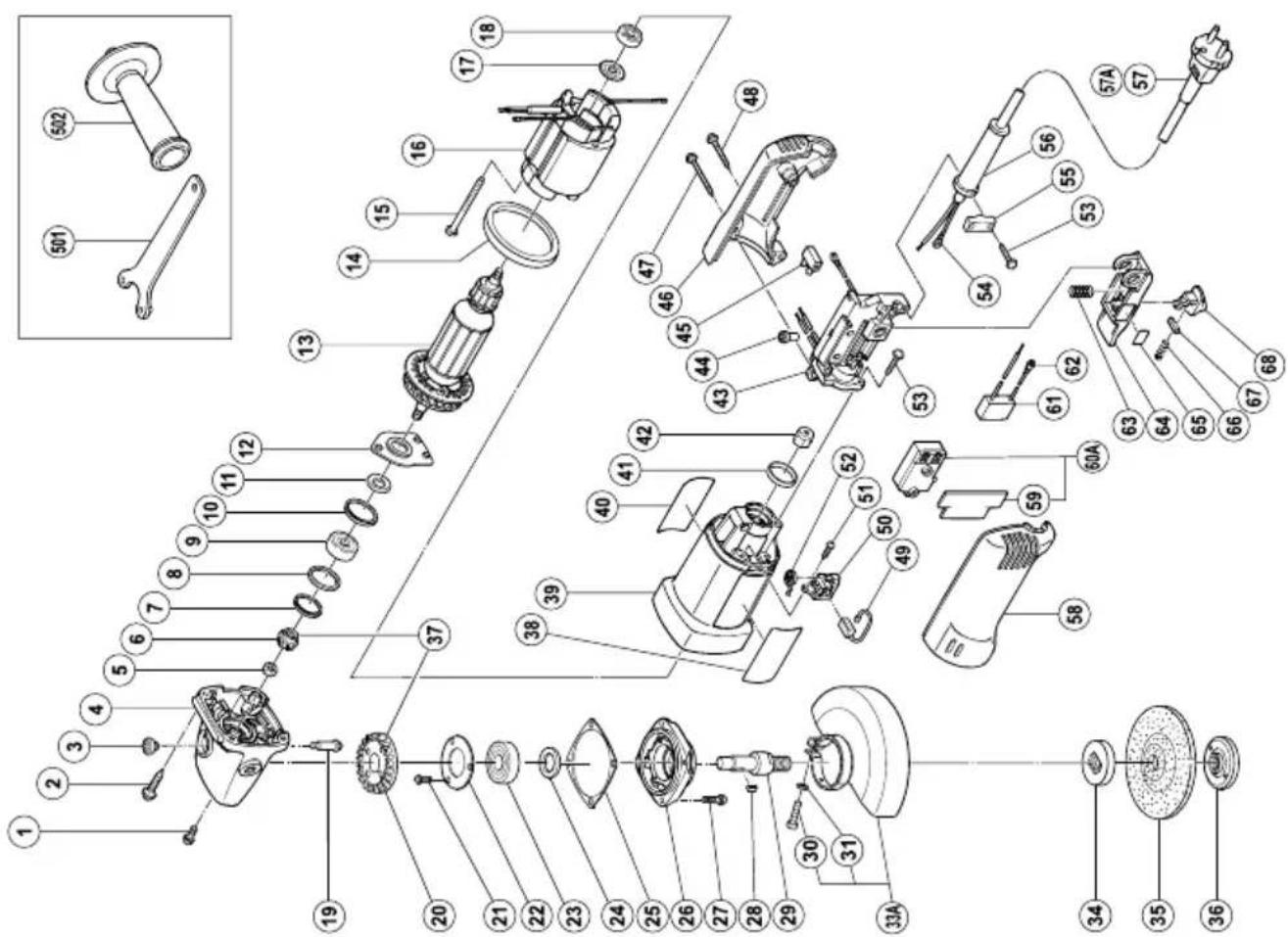
6. Service parts list
A: Item No.
B: Code No.
C: No. Used
D: Remarks
CAUTION:
Repair, modification and inspection of Hitachi Power Tools must be carried out by a Hitachi Authorized Service Center.
This Parts List will be helpful if presented with the tool to the Hitachi Authorized Service Center when requesting repair or other maintenance.
In the operation and maintenance of power tools, the safety regulations and standards prescribed in each country must be observed.
MODIFICATIONS:
Hitachi Power Tools are constantly being improved and modified to incorporate the latest technological advancements.
Accordingly, some parts (i.e. code numbers and/or design) may be changed without prior notice.
NOTE
Due to HITACHI's continuing program of research and development, the specifications herein are subject to change without prior notice.
Information concerning airborne noise and vibration
The measured values were determined according to EN 60745 and declared in accordance with ISO 4871.
Measured A-weighted sound power level: 95 dB (A)
Measured A-weighted sound pressure level: 84 dB (A)
Uncertainty KpA: 3 dB (A)
Wear ear protection.
The typical weighted root mean square acceleration value: 2.5 m/s ^4 .
G13YC
| A | B | C | D |
| 41 | 995-662 | 1 | |
| 42 | 302-062 | 1 | |
| 43 | 1 | 308-550 | 1 110V |
| 43 | 2 | 308-551 | 1 230V |
| 43 | 3 | 308-552 | 1 240V |
| 44 | 959-140 | 1 | |
| 45 | 938-307Z | 1 | |
| 46 | 308-549 | 1 | |
| 47 | 303-694 | 2 D4X35 | |
| 48 | 301-653 | 1 D4X20 | |
| 49 | 999-087 | 2 | |
| 50 | 308-535 | 2 | |
| 51 | 306-945 | 4 D3X10 | |
| 52 | 308-536 | 2 | |
| 53 | 994-750 | 3 D4X16 | |
| 54 | 980-063 | 1 | |
| 55 | 960-266 | 1 | |
| 56 | 953-327 | 1 D8.8 | |
| 57 | — | 1 | |
| 58 | 308-548 | 1 | |
| 59 | 308-553 | 1 | |
| 60A | 308-400 | 1 | |
| 61 | 930-039 | 1 | |
| 62 | 980-063 | 1 | |
| 63 | 983-595 | 1 | |
| 64 | 308-554 | 1 | |
| 65 | 308-557 | 1 | |
| 66 | 301-631 | 1 | |
| 67 | 982-696 | 1 3X3X15 | |
| 68 | 308-555 | 1 | |
| 501 | 938-332Z | 1 | |
| 502 | 994-322 | 1 |
| A | B | C | D |
| 1 303-255 3 M4X10 | |||
| 2 937-807 4 D5X25 | |||
| 3 301-944 1 | |||
| 4 308-542 1 "3, 19" | |||
| 5 301-941 1 M7 | |||
| 6 308-541 1 | |||
| 7 308-543 1 | |||
| 8 980-866 1 | |||
| 9 629-T12 1 | 629T12DDC3PS2-L | ||
| 10 957-754 1 | |||
| 11 994-320 1 | |||
| 12 308-538 1 | |||
| 13 1 360-344K 1 110V | |||
| 13 2 360-333E 1 230V-240V | |||
| 14 308-537 1 | |||
| 15 982-021 2 D4X70 | |||
| 16 1 340-296C 1 110V | |||
| 16 2 340-296E 1 230V-240V | |||
| 17 956-387 1 | |||
| 18 608-VVM 1 | 608VVMC2EPS2S | ||
| 19 301-943 1 | |||
| 20 308-540 1 | |||
| 21 991-207 3 M4X8 | |||
| 22 936-680 1 | |||
| 23 620-1DD 1 | 6201DDUCMAV2S | ||
| 24 308-546 1 | |||
| 25 308-547 1 | |||
| 26 308-545 1 | |||
| 27 307-046 4 M5X16 | |||
| 28 944-109 1 3X3X8 | |||
| 29 994-301 1 | |||
| 30 949-241 1 M5X20 | |||
| 31 949-454 1 M5 | |||
| 33A 320-192 1 "30, 31" | |||
| 34 937-817Z 1 | |||
| 35 938-300Z 1 125MM A36Q | |||
| 36 994-324 1 M14 | |||
| 37 308-539 1 "6, 20" | |||
| 38 —— 1 | |||
| 39 308-559 1 | |||
| 40 —— 1 | |||
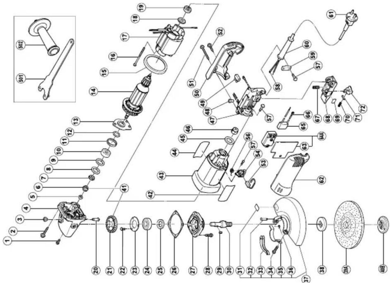
G15YC
| A | B | C | D | A | B | C | D |
| 1 | 303-255 | 3 | M4X10 | 41 | 311-486 | 1 | “6, 21” |
| 2 | 937-807 | 4 | D5X25 | 42 | — | 1 | |
| 3 | 301-944 | 1 | 43 | 308-559 | 1 | ||
| 4 | 308-542 | 1 | “3, 19” | 44 | — | 1 | |
| 5 | 309-191 | 1 | M6 | 45 | 995-662 | 1 | |
| 6 | 311-487 | 1 | 46 | 302-062 | 1 | ||
| 7 | 311-489 | 1 | 47 | 1 | 308-550 | 1 110V | |
| 8 | 308-543 | 1 | 47 | 2 | 308-551 | 1 230V | |
| 9 | 980-866 | 1 | 47 | 3 | 308-552 | 1 240V | |
| 10 | 629-T12 | 1 | 629T12DDC3PS2-L | 48 | 959-140 | 1 | |
| 11 | 957-754 | 1 | 49 | 938-307Z | 1 | ||
| 12 | 994-320 | 1 | 50 | 308-549 | 1 | ||
| 13 | 308-538 | 1 | 51 | 303-694 | 2 D4X35 | ||
| 14 | 1 | 360-372 | 1 110V | 52 | 301-653 | 1 D4X20 | |
| 14 | 2 | 360-373E | 1 230V | 53 | 999-087 | 2 | |
| 15 | 308-537 | 1 | 54 | 308-535 | 2 | ||
| 16 | 982-021 | 2 | D4X70 | 56 | 308-536 | 2 | |
| 17 | 1 | 340-296C | 1 110V | 57 | 994-750 | 3 D4X16 | |
| 17 | 2 | 340-296E | 1 230V-240V | 58 | 980-063 | 1 | |
| 18 | 956-387 | 1 | 59 | 960-266 | 1 | ||
| 19 | 608-VVM | 1 | 608VVMC2EPS2S | 60 | 1 | 953-327 | 1 D8.8 |
| 20 | 301-943 | 1 | 60 | 2 | 938-051 | 1 D10.1 | |
| 21 | 311-488 | 1 | 61 | — | 1 | ||
| 22 | 991-207 | 3 | M4X8 | 62 | 308-548 | 1 | |
| 23 | 936-680 | 1 | 63 | 308-553 | 1 | ||
| 24 | 620-1DD | 1 | 6201DDUCMAV2S | 64A | 308-400 | 1 | |
| 25 | 308-546 | 1 | 65 | 994-273 | 1 | ||
| 26 | 308-547 | 1 | 66 | 980-063 | 1 | ||
| 27 | 308-545 | 1 | 67 | 983-595 | 1 | ||
| 28 | 307-046 | 4 | M5X16 | 68 | 308-554 | 1 | |
| 29 | 944-109 | 1 | 3X3X8 | 69 | 308-557 | 1 | |
| 30 | 994-301 | 1 | 70 | 301-631 | 1 | ||
| 31 | 311-492 | 1 | 71 | 982-696 | 1 3X3X15 | ||
| 32 | 311-744 | 1 | 72 | 308-555 | 1 | ||
| 33 | 311-743 | 1 | 501 | 937-913Z | 1 | ||
| 34 | 880-734 | 1 | M5X25 | 502 | 994-322 | 1 | |
| 35 | 311-491 | 1 | |||||
| 36 | 874-759 | 1 | |||||
| 37 | 311-940 | 1 | “31-36” | ||||
| 38 | 937-817Z | 1 | |||||
| 39A | 316-823 | 1 | 150MM A36Q | ||||
| 40B | 937-909Z | 1 | M14 |
natural_image
Line drawing of a quill pen with inkwell (no text or symbols)
natural_image
Line drawing of a quill pen with inkwell (no text or symbols)Hitachi Power Tools Norway AS
Kjeller Vest 7
Postboks 124, 2007 Kjeller, Norway
Tel: (+47) 6692 6600
Fax: (+47) 6692 6650
URL: http://www.markt.no
Hitachi Power Tools Sweden AB
Rotebergsvagen 2B
SE-192 78 Sollentuna, Sweden
Tel: (+46) 8 598 999 00
Fax: (+46) 8 598 999 40
URL: http://www.markt.se
Hitachi Power Tools Denmark AS
Lillebaeltsvej 90
DK-6715 Esbjerg N, Denmark
Tel: (+45) 75 14 32 00
Fax: (+45) 75 14 36 66
URL: http://www.markt.dk
Hitachi Power Tools Finland OY
Tupalankatu 9
FIN-15680 Lahti, Finland
Tel: (+358) 20 7431 530
Fax: (+358) 20 7431 531
URL: http://www.markt.fi
| Svenska | Suomi | ||
| EF-DEKLARATION BETRÄFFANDE LIKFORMIGHETVi tillkännagiver med eget ansvar att denna produktöverensstämmer med standard eller standardiseratdokument EN60745, EN55014 och EN61000 i enlighetmed räddirektiven 2004/108/EF och 98/37/EF. Dennaprodukt uppfyller även de nödvändiga kraven för 2006/42/EF som kommer att gälla istället för 98/37/EF från 29december 2009.Den europeiska standardansvarige på Hitachi Koki EuropeLtd. är auktoriserad att utarbeta den tekniska filen.Denna deklaration gäller för CE-märkningen påprodukten. | EY-ILMOITUS YHDENMUKAISUUDESTAYksinomaisella vastuudella vakuutamme, että tämä tuote vastaa normeja tai normitettuja dokumentteja EN60745,EN55014 ja EN61000 yhteisön ohjeiden 2004/108/EY ja98/37/EY mukaisesti. Tämä tuote täyttää myös direktiivin98/37/EY sijasta 29. joulukuuta 2009 lähtien sovellettavandirektiivin 2006/42/EY olennaiset vaatimukset.Hitachi Koki Europe Ltd.:n eurooppalaisten standardienjohtaja on valtuutettu laatimaan tekniset asiakirjat.Tämä ilmoitus sovelletaan tuotekohtaiseen CE-merkintään. | ||
| Dansk | English | ||
| EF-OVERENSS TEMMELSESERKLÆRINGVi erlkærer os fuldstændige ansvarlige for, at detteprodukt modsvarer gældende standard eller destandardiserede dokumenter EN60745, EN55014 ogEN61000 i overensstemmelse med EF-direktiver 2004/108/EF og 98/37/EF. Dette produkt opfylder også deobligatoriske krav i 2006/42/EF, der anvendes fra d. 29.december 2009 i stedet for 98/37/EF.Chefen for europæiske standarder hos Hitachi Koki EuropeLtd. er autoriseret til at kompilere den tekniske fil.Denne erklæring qælder produkter, der er mærket medCE. | EC DECLARATION OF CONFORMITYWe declare under our sole responsibility that this productis in conformity with standards or standardizeddocuments EN60745, EN55014 and EN61000 inaccordance with Council Directives 2004/108/EC and 98/37/EC. This product also complies with the essentialrequirements of 2006/42/EC to be applied from 29December 2009 instead of 98/37/EC.The European Standards Manager at Hitachi Koki EuropeLtd. is authorized to compile the technical file.This declaration is applicable to the product affixed CE marking. | ||
| Norsk | |||
| EF'S ERKLÆRING OM OVERENSSTEMMELSEVi erklærer herved at vi påtar oss eneansvaret for atdette produktet er i overensstermmelse med normer ellerstandardiserte dokumenter EN60745, EN55014 ogEN61000 i samsvar med Rådsdirektiver 2004/108/EF og98/37/EF. Dette produktet følger de vesentlige kravene i2006/42/EF som gjelder fra 29. desember 2009 i stedetfor 98/37/EF.Lederen for europeiske standarder ved Hitachi Koki EuropeLtd. har fullmakt til å utarbeide det tekniske dokumentet.Denne erklæringen gjelder produktets påklistrede CE-merking. | |||
| Representative office in EuropeHitachi Power Tools Europe GmbHSiemensring 34, 47877 Willich 1, F. R. GermanyTechnical file at:Hitachi Koki Europe Ltd.Clonshaugh Business & Technology Park, Dublin 17,IrelandHead office in JapanHitachi Koki Co., Ltd.Shinagawa Intercity Tower A, 15-1, Konan 2-chome,Minato-ku, Tokyo, Japan | |||
