
G 18SE2 - Grinder HITACHI - Free user manual and instructions
Find the device manual for free G 18SE2 HITACHI in PDF.


| Product Type | Angle Grinder |
| Brand | Hitachi (now Metabo HPT) |
| Model | G 18SE2 |
| Wheel Diameter | 4.5 inches (115 mm) |
| Motor Power | 6.6 Amps |
| No Load Speed | 11,000 RPM |
| Spindle Thread | 5/8-11 UNC |
| Weight | 5.3 lbs (2.4 kg) |
| Overall Length | 10.6 inches (270 mm) |
| Power Source | Corded, 120V AC |
| Switch Type | Slide switch with lock |
| Grip | D-shaped handle with rubberized grip |
| Side Handle | Included, adjustable position |
| Spindle Lock | Yes, for easy wheel changes |
| Safety Guard | Adjustable, tool-free |
| Protection Class | Class II (double insulated) |
| Bearing Type | Ball bearings |
| Applications | Cutting, grinding, polishing metal and masonry |
| Maintenance | Periodic brush replacement, keep vents clean |
| Repairability | Replaceable brushes, available spare parts |
Frequently Asked Questions - G 18SE2 HITACHI
User questions about G 18SE2 HITACHI
0 question about this device. Answer the ones you know or ask your own.
Ask a new question about this device
Download the instructions for your Grinder in PDF format for free! Find your manual G 18SE2 - HITACHI and take your electronic device back in hand. On this page are published all the documents necessary for the use of your device. G 18SE2 by HITACHI.
USER MANUAL G 18SE2 HITACHI
INSTRUCTION MANUAL AND SAFETY INSTRUCTIONS FOR DISC GRINDER
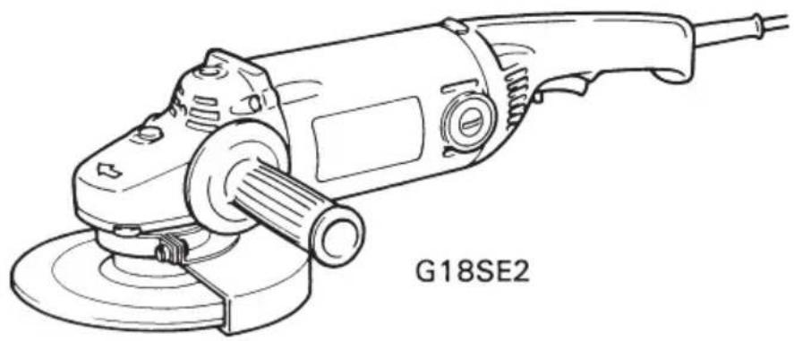
MODEL G 18SE2 · G 23SC2
natural_image
Line drawing of a power tool labeled G18SE2, showing mechanical components and base (no text or symbols on the diagram itself)WARNING:
Improper and unsafe use of this power tool can result in death or serious bodily injury!
This manual contains important information about product safety. Please read and understand this manual before operating the power tool. Please keep this manual available for others before they use the power tool.
- CONTENTS -
Page
IMPORTANT INFORMATION 3
MEANINGS OF SIGNAL WORDS 3
SAFETY
IMPORTANT SAFETY INSTRUCTIONS
FOR USING ALL POWER TOOLS 4
IMPORTANT SAFETY INSTRUCTIONS
FOR USE OF THE DISC GRINDER 8
REPLACEMENT PARTS 8
POLARIZED PLUGS 8
USE OF EXTENSION CORD 9
DOUBLE INSULATION FOR SAFER OPERATION....10
SERVICE AND REPAIRS 18
PARTS LIST 19
IMPORTANT INFORMATION
Read and understand all of the operating instructions, safety precautions and warnings in the Instruction Manual before operating or maintaining this power tool.
Most accidents that result from POWER TOOL operation and maintenance are caused by the failure to observe basic safety rules or precautions. An accident can often be avoided by recognizing a potentially hazardous situation before it occurs, and by observing appropriate safety procedures.
Basic safety precautions are outlined in the "SAFETY" section of this Instruction Manual and in the sections which contain the operation and maintenance instructions.
Hazards that must be avoided to prevent bodily injury or machine damage are identified by WARNINGS on the power tool and in this Instruction Manual.
Never use this power tool in a manner that has not been specifically recommended by HITACHI, unless you first confirm that the planned use will be safe for you and others.
MEANINGS OF SIGNAL WORDS
WARNING indicates a potentially hazardous situations which, if ignored, could result in serious personal injury.
CAUTION indicates a hazardous situations which, if ignored, could result in moderate personal injury, or could cause machine damage.
NOTE emphasizes essential information.
SAFETY
IMPORTANT SAFETY INSTRUCTIONS FOR USING ALL POWER TOOLS

WARNING: Death or serious bodily injury could result from improper or unsafe use of power tools. To avoid these risks, follow these basic safety instructions:
READ ALL INSTRUCTIONS
Never place your hands, fingers or other body parts near the tool's moving parts.
2. NEVER OPERATE WITHOUT ALL GUARDS IN PLACE.
Never operate this tool without all guards or safety features in place and in proper working order. If maintenance or servicing requires the removal of a guard or safety feature, be sure to replace the guard or safety feature before resuming operation of the tool.
3. ALWAYS WEAR EYE AND EAR PROTECTION.
Protect yourself from flying or expelled wood chips, metal particles or other debris by using safety goggles or equivalent eye protection. Wear ear protection to protect yourself from excessive noise.
4. PROTECT YOURSELF AGAINST ELECTRIC SHOCK.
Prevent body contact with grounded surfaces such as pipes, radiators, ranges and refrigeration enclosures. Never operate the tool in damp or wet locations.
5. DISCONNECT TOOLS.
Never leave the tool connected to a power source. Always disconnect the tool from its power source before servicing, inspecting, maintaining, cleaning and before changing or checking any parts.
6. AVOID UNINTENTIONAL STARTING.
Don't carry the tool while it is connected to its power source. Don't carry the tool with your finger near the power switch. Be sure the power switch is in the "off" position before connecting the tool to its power source.
7. STORE TOOL PROPERLY.
When not in use, the tool should be stored in a dry place. Keep out of reach of children. Lock-out the storage area.
8. KEEP WORK AREA CLEAN.
Cluttered areas and benches invite injuries. Clear all work areas and work benches of unnecessary tools, debris, furniture, etc.
9. CONSIDER WORK AREA ENVIRONMENT.
Don't expose power tools to rain. Don't use power tools in damp or wet locations. Keep work area well lit and well ventilated.
Don't use tool in presence of flammable liquids or gases.
Power tools produce sparks during operation. They also spark when switching ON/OFF. Never use power tools in sites containing lacquer, paint, benzine, thinner, gasoline, gases, adhesive agents, and other materials which are combustible or explosive.
10. KEEP CHILDREN AWAY.
Do not let visitors contact tool or extension cord.
All visitors should be kept safely away from work area.
11. DON'T FORCE TOOL.
It will do the job better and safer at the rate for which it was intended.
12. USE RIGHT TOOL.
Don't force small tool or attachment to do the job of a heavy-duty tool.
Don't use tool for purpose not intended – for example — don't use circular saw for cutting tree limbs or logs.
13. DRESS PROPERLY.
Do not wear loose clothing or jewelry. They can be caught in moving parts. Rubber gloves and non-skid footwear are recommended when working outdoors.
Wear protective hair covering to contain long hair.
14. USE FACE, DUST MASK OR RESPIRATOR IF OPERATION IS DUSTY.
All persons in the area where power tools are being operated should also wear face, dust masks or respirator.
15. DON'T ABUSE CORD.
Never carry tool by cord or yank it to disconnect from receptacle.
Keep cord from heat, oil and sharp edges.
16. SECURE WORK.
Use clamps or a vise to hold work. It's safer than using your hand and it frees both hands to operate tool.
17. DON'T OVERREACH.
Keep proper footing and balance at all times.
18. MAINTAIN TOOLS WITH CARE.
Keep tools sharp and clean for better and safer performance.
Follow instructions for lubricating and changing accessories.
Inspect tool cords periodically and if damaged, have repaired by authorized service facility. Inspect extension cords periodically and replace if damaged.
Keep handles dry, clean, and free from oil and grease.
- REMOVE ADJUSTING KEYS AND WRENCHES.
Keys and adjusting wrenches remove from tool before turning it on.
- OUTDOOR USE EXTENSION CORDS.
When tool is used outdoors, use only extension cords intended for use outdoors and so marked.
- STAY ALERT.
Watch what you are doing. Use common sense. Do not operate tool when you are tired.
Tools should never be used by you if you are under the influence of alcohol, drugs or medication that makes you drowsy.
- CHECK DAMAGED PARTS.
Before further use of the tool, a guard or other part that is damaged should be carefully checked to determine that it will operate properly and perform its intended function. Check for alignment of moving parts, binding of moving parts, breakage of parts, mounting, and any other conditions that may affect its operation.
A guard or other part that is damaged should be properly repaired or replaced by an authorized service center unless otherwise indicated elsewhere in this Instruction Manual.
Have defective switches replaced by authorized service center.
Do not use tool if switch does not turn it on and off.
- NEVER USE A POWER TOOL FOR APPLICATIONS OTHER THAN THOSE SPECIFIED.
Never use a power tool for applications other than those specified in the Instruction Manual.
- HANDLE TOOL CORRECTLY.
Operate the tool according to the instructions provided herein. Do not drop or throw the tool. Never allow the tool to be operated by children, individuals unfamiliar with its operation or unauthorized personnel.
- CHECK FOR LIVE WIRES.
Avoid the risk of severe electrical shock by checking for live electrical wires that may be hidden by walls, floors or ceilings. The wires should be de-energized before work begins.
- KEEP ALL SCREWS, BOLTS AND COVERS TIGHTLY IN PLACE.
Keep all screws, bolts, and plates tightly mounted. Check their condition periodically.
- DO NOT USE POWER TOOLS IF THE PLASTIC HOUSING OR HANDLE ARE CRACKED.
Cracks in the tool's housing or handle can lead to electric shock. Such tools should not be used until repaired.
- BLADES AND ACCESSORIES MUST BE SECURELY MOUNTED TO THE TOOL.
Prevent potential injuries to yourself or others. Blades, cutting implements and accessories which have been mounted to the tool should be secure and tight.
- KEEP MOTOR AIR VENT CLEAN.
The tool's motor air vent must be kept clean so that air can freely flow at all times. Check for dust build-up frequently.
- OPERATE POWER TOOLS AT THE RATED VOLTAGE.
Operate the power tool at voltages specified on their nameplates.
If using the power tool at a higher voltage than the rated voltage, it will result in abnormally fast motor revolution and may damage the unit and burn up the motor.
- NEVER USE A TOOL WHICH IS DEFECTIVE OR OPERATING ABNORMALLY
If the tool appears to be operating unusually, making strange
noises, or otherwise appears defective, stop using it immediately and arrange for repairs by a Hitachi authorized service center.
Don't leave tool until it comes to a complete stop.
- CAREFULLY HANDLE POWER TOOLS.
Should a power tool be dropped or struck against hard materials inadvertently it may be deformed, cracked, or damaged.
- DO NOT WIPE PLASTIC PARTS WITH SOLVENT.
Solvents such as gasoline, thinner, benzine, carbon tetrachloride, and alcohol may damage and crack plastic parts. Do not wipe them with such solvents.
Wipe plastic parts with a soft cloth lightly dampened with soapy water and dry thoroughly.
- USE ONLY AUTHENTIC HITACHI REPLACEMENT PARTS.
Replacement parts not manufactured by Hitachi may void your warranty and can lead to malfunction and resulting injuries. Authentic Hitachi parts are available from your dealer.
- Use only grinding wheels having a maximum operating speed at least high as 6600 RPM.
IMPORTANT SAFETY INSTRUCTIONS FOR USE OF THE DISC GRINDER

WARNING: Death or serious bodily injury could result from improper or unsafe use of disc grinder. To avoid these risks, follow these basic safety instructions:
- NEVER operate the disc grinder without its wheel guard in place.
- NEVER place hands or body parts near the disc during operation.
- NEVER use a grinding wheel which is cracked or deformed or worn away.
- NEVER use a grinding wheel with an RPM rating which is less than 6600 RPM. The wheel can disintegrate during use and cause severe injuries.
- NEVER use the grinder in places where the sparks generated by the grinder can cause explosion, such as where flammable materials or gases are present.
- ALWAYS wear eye protection that meets the requirement of the latest revision of ANSI Standard Z87.1. Also protect your ears from excessive noise.
- ALWAYS wear a mask or respirator to protect yourself from dust or potentially harmful particles generated during the grinding operation.
- ALWAYS firmly grip the side handle while operating the grinder.
- ALWAYS follow the instructions contained in this manual when replacing the grinding wheel.
REPLACEMENT PARTS
When servicing use only identical replacement parts.
Repairs should be conducted only by a Hitachi authorized service center.
POLARIZED PLUGS
To reduce the risk of electric shock, this equipment has a polarized plug (one blade is wider than the other).
This plug will fit in a polarized outlet only one way.
If the plug does not fit fully in the outlet, reverse the plug.
If it still does not fit, contact a qualified electrician to install the proper outlet.
Do not change the plug in any way.
USE OF EXTENSION CORD
Make sure your extension cord is in good condition. When using an extension cord, be sure to use one heavy enough to carry the current your product will draw. An undersized cord will cause a drop in line voltage resulting in loss of power and overheating. Table shows the correct size to use depending on cord length and nameplate ampere rating. If in doubt, use the next heavier gage. The smaller the gage number, the heavier the cord.
MINIMUM GAGE FOR CORD SETS
| Total Length of Code in Feet (Meter) | |||||
| 0-25(0-7.6) | 26-50(7.9-15.2) | 51-100(15.5-30.5) | 101-150(30.8-45.7) | ||
| Ampere More Than | Rating Not More Than | AWG | |||
| 0-6 | 18 | 16 | 16 | 14 | |
| 6-10 | 18 | 16 | 14 | 12 | |
| 10-12 | 16 | 16 | 14 | 12 | |
| 12-16 | 14 | 12 | Not Recommended | ||

WARNING: Avoid electrical shock hazard. Never use this tool with a damaged or frayed electrical cord or extension cord. Inspect all electrical cords regularly. Never use in or near water or in any environment where electric shock is possible.
To ensure safer operation of this power tool, HITACHI has adopted a double insulation design. "Double insulation" means that two physically separated insulation systems have been used to insulate the electrically conductive materials connected to the power supply from the outer frame handled by the operator. Therefore, either the symbol "回" or the words and "Double insulation" appear on the power tool or on the nameplate.
Although this system has no external grounding, you must still follow the normal electrical safety precautions given in this Instruction Manual, including not using the power tool in wet environments.
To keep the double insulation system effective, follow these precautions:
○ Only HITACHI AUTHORIZED SERVICE CENTER should disassemble or assemble this power tool, and only genuine HITACHI replacement parts should be installed.
○ Clean the exterior of the power tool only with a soft cloth moistened with soapy water, and dry thoroughly.
Never use solvents, gasoline or thinners on plastic components; otherwise the plastic may dissolve.
SAVE THESE INSTRUCTIONS AND MAKE THEM AVAILABLE TO OTHER USERS OF THIS TOOL!
The information contained in this Instruction Manual is designed to assist you in the safe operation and maintenance of the power tool.
Some illustrations in this Instruction Manual may show details or attachments that differ from those on your own power tool.
NAME OF PARTS

Fig. 1
SPECIFICATIONS
| Model | G 18SE2 | G 23SC2 |
| Motor | Single-Phase, Series: Wound Commutator Motor | |
| Power Source | Single-Phase 115V AC/DC 60Hz | |
| Input | 1,640W | |
| No-Load Speed (USA) | 6,000 rpm | 6,000 rpm |
| No-Load Speed (Canada) | 8,500 rpm | 6,600 rpm |
| Wheel Sizeexternal diam.internal diam. | 7" (180mm)7/8"(22mm) | 9" (230mm)7/8"(22mm) |
| Sanding Disc Sizeexternal diam.internal diam. | 7" (180mm)7/8"(22mm) | 7" (180mm)7/8"(22mm) |
| Spindle Thread | 5/8"-11UNC | 5/8"-11UNC |
| Weight | 11 lbs (5.0 kg) | |
ACCESSORIES

WARNING: NEVER use any accessories other than those mentioned below. The use of any accessories other than those mentioned below or attachments not intended for use such as cup wheel, cut-off wheel or saw blade is dangerous and may cause personal injury or property damage.
STANDARD ACCESSORIES
(1) Wrench(B) (Code No.937913Z) 1
(2) Side Handle (Code No.937981Z) 1
(3) Hexagon Bar Wrench (Code No.872422) 1
OPTIONAL ACCESSORIES…sold separately
○ Grinding Wheel (10 pcs. per package) 1
| Dimensions | Code No. |
| 7"(180mm) external diam.×1/4"(6mm) thickness×7/8"(22mm) internal diam.......G 18SE2 | 701070 |
| 9"(230mm) external diam.×1/4"(6mm) thickness×7/8"(22mm) internal diam.......G 23SC2 | 701090 |
○ Sanding Disc Set for 7"(180mm) disc (Code No.953256Z) (including the following parts 1 each—Fig.2, ①\~④)
① Sanding Disc
| 7"(180mm) diameter | ||
| Grit | Code No. | Q'ty |
| 16 | 939040 | 10 |
| 20 | 939041 | |
| 24 | 939042 | |
| 30 | 939043 | |
| 36 | 939044 | |
| 40 | 939045 | |
| 50 | 939047 | |
| 60 | 939048 | |
| 80 | 939049 | |
| 100 | 939050 | |
| 120 | 939051 | |

② Rubber Pad (Code No.953255P) external diam. 6-3/4"(170mm) internal diam. 5/8"(16mm)
③ Washer Nut (Code No.953254P) thread 5/8"-11UNC
Fig. 2
④ Wrench(B) (Code No.937913Z)
NOTE:
Accessories are subject to change without any obligation on the part of the HITACHI.
APPLICATIONS
For use as a Grinder
○ Removal of casting fin and finishing of various type of steel, bronze and aluminum materials and castings.
○ Grinding of welded sections or sections cut by means of welding.
○ Grinding of synthetic resins, slate, brick, marble, etc.
- Preliminary sanding of metal surfaces before painting, rust removal, removing old paint before repainting.
○ Finishing woodwork, correcting projections of timbers from joints or assemblies.
○ Preliminary sanding of wood surfaces before applying paint.
PRIOR TO OPERATION
- Power source
Ensure that the power source to be utilized conforms to the power source requirements specified on the product nameplate.
- Power switch
Ensure that the switch is in the OFF position. If the plug is connected to a receptacle while the switch is in the ON position, the power tool will start operating immediately and can cause serious injury.
- Extension cord
When the work area is far away from the power source, use an extension cord of sufficient thickness and rated capacity (refer to page 9). The extension cord should be kept as short as practicable.
- Check the receptacle
If the receptacle only loosely accepts the plug, the receptacle must be repaired. Contact a licensed electrician to make appropriate repairs.
If such a fautly receptacle is used, it may cause overheating, resulting in a serious hazard.
- Check your working environment
Ensure the following before operation;
○ No flammable gas, liquid, or object at worksite.
○ Grinding thin steel sheet may cause a high booming sound. In this case, place a rubber mat under the workpiece.
○ Take appropriate noise preventive measures to prevent adverse affects on the environment by electrical noise.
○ Clear the area of children or unauthorized personnel.
- Mounting the wheel guard
Be sure to mount the wheel guard at an angle that will protect the operator's body from injury by a broken wheel piece.

WARNING: If not correctly attaching a proper wheel guard, it may lead to severe injury or death if the grinding wheel should be broken.
- Inspect the grinding wheel carefully before mounting.
Thoroughly check that a specified grinding wheel free of cracks and splits is mounted. Make sure that the grinding wheel is firmly clamped and has been mounted in accordance with the instructions contained on page 15.
- Test the grinder before using.
Before actually beginning the grinding work, test the grinder by first clearing the area of all other personnel. Make sure the wheel guard is in place and that you are wearing eye protection. Turn the grinder "on" and make sure the grinder runs smoothly and shows on abnormalities.
Duration of the trial run is as follows:
When grinding wheel is replaced .... 3 minutes or more
When starting daily work .... 1 minute or more
- Use only properly rated grinding wheels.
Use only grinding wheels rated at 6600 RPM or more.
Using a grinding wheel rated less can lead to wheel disintegration during operation and serious bodily injury.
- Check the spindle lock
Make sure that the push button is disengaged by pushing push button two or three times before turning on the grinder.
- Switch operation
This enables the grinder always to be controlled with the hand gripping the machine for maximum safety during grinding operations.
Switch ON : Press the switch lever.
Switch OFF : Release the switch lever.
Switch ON : Press the switch lever. The switch lever is locked by pull the locking button.
Switch OFF : Press and release the switch lever.
ASSEMBLING AND DISASSEMBLING THE WHEEL GUARD, GRINDING WHEEL AND SANDING DISC

WARNING: Be sure to switch power OFF and disconnect the plug from the receptacle to avoid serious trouble.
1. Assembling
(1) Turn the disc grinder upsidedown so that the spindle is facing upward.
(2) To mount the wheel guard on the grinder first, slip the set ring (A) over the guard mounting flange, so locating pin fits in the guard locating groove, then twist guard in the groove into a proper angle, so the guard will protect the operator's body from injury by a broken wheel piece.
(3) Tighten the screw in the set ring (A) of guard.
(4) To mount a grinding wheel on the grinder, first align the oval-shaped indentation of the wheel washer with the notched part of the spindle, then attach them.
(5) Fit the protuberance of the grinding wheel onto the wheel washer.
(6) Screw the wheel nut onto the spindle.
(7) While pushing the push button with one hand, lock the spindle by turning the grinding wheel slowly with the other hand.
(8) Tighten the wheel nut by using the supplied wrench as shown in Fig.3.
(1) After placing the Sanding disc on the rubber pad, insert the washer nut through the spindle.
(2) While pushing the push button with one hand, lock the spindle by turning the sanding disc slowly with the other hand.
(3) Secure the sanding disc and rubber pad by tightening the washer nut with the wrench.

CAUTION: Make sure that the grinding wheel or sanding disc and rubber pad are mounted firmly.
2. Disassembling
To remove the wheel guard, the grinding wheel, the sanding disc, follow the above-mentioned procedure in reverse order.
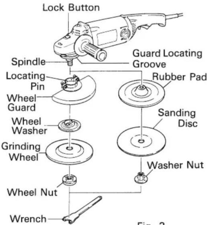
Fig. 3
PRACTICAL GRINDER AND SANDER APPLICATIONS
- Always hold the handle and side handle of the POWER TOOL firmly.
Otherwise the counterforce produced may result in inaccurate and even dangerous operation. - Grinding pressure
Since grinding by utilizing only the Disc Grinder's own weight is feasible, hold the Disc Grinder so that it only slightly contacts the plane to be ground.
CAUTION:
- Do not press the Disc Grinder forcibly against the plane to be ground. Heavy pressure will reduce the revolving speed and such deteriorate the finished surface, and phenomena as overload will lead to burning loss of the motor.
- Grinding angle
Use only its peripheral surface by tilting the grinding wheel at an angle of 15^ 30^ , as shown in Fig.4-a.
CAUTION:
- Do not utilize the entire surface of grinding wheel when grinding.
- When using a new grinding wheel in direction A (Fig.4-a), the wheel edge may cut into the workpiece. In this case, grind in direction B (Fig.4-a). Once the wheel edge is worn, the workpiece can be ground in both directions.
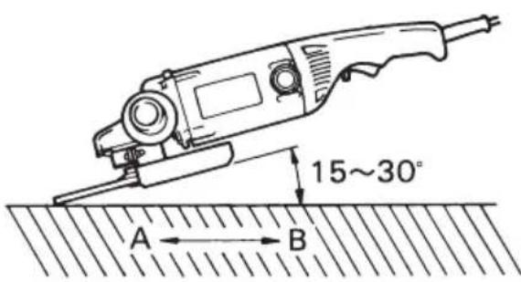
Fig. 4-a
The provided grinding wheel (resinoid wheel) is rated as Class A grain and #24 grain size. Therefore, it is most appropriate for heavy grinding of general steel materials.
It is also suitable for grinding other types of materials.
For a fine finish, lift the disc grinder slightly and grind slowly at the appropriate speed.
5. Precaution after use.
Do not lay the grinder down immediately after use in a place where there are many shavings and much dirt and dust until it has completely stopped revolving.
- Do not push the sanding disc to the surface to be ground.
CAUTION:
- Do not press the Disc Grinder forcibly against the plane to be ground. Heavy pressure will reduce the revolving speed and such deteriorate the finished surface, and phenomena as overload will lead to burning loss of the motor.
- Sanding angle
Use only its peripheral surface by tilting the sanding disc at an angle of 15^ 30^ , as shown in Fig.4-b.

Fig. 4-b
CAUTION:
- Do not utilize the entire surface of sanding disc when sanding.
MAINTENANCE AND INSPECTION
⚠ WARNING: Be sure to switch power OFF and disconnect the plug during maintenance and inspection.
- Replacing the grinding wheel
Replace the grinding wheel when it has been worn out to about 2-3/8"(60mm) in external diameter. Confirm that there is no crack or any damage to the grinding wheel. If there is a crack or a transformation in the wheel, replace it immediately.
- Inspecting the mounting screws
Regularly inspect all mounting screws and ensure that they are properly tightened. Should any of the screws be loose, retighten them immediately.
⚠ WARNING: Using this grinder with loosen screws is extremely dangerous.
- Confirm that there is no damage in the wheel guard, the cord and the housing, etc.
Furthermore, confirm that there is no abnormality in the activation of the switch.
- Inspecting the carbon brushes (Fig. 5)
The motor employs carbon brushes which are consumable parts. Replace the carbon brush with a new one when it becomes worn to its wear limit. Always keep carbon brushes clean and ensure that they slide freely within the brush holders.

CAUTION: Using this grinder with a carbon brush which is worn in excess of the wear limit will damage the motor.
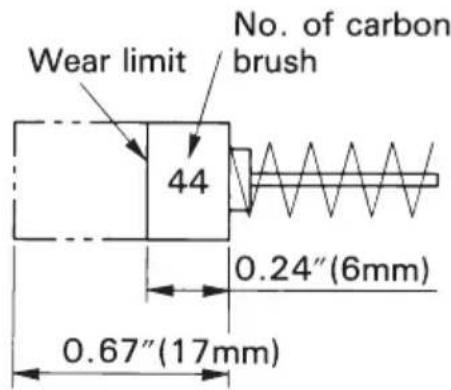
Fig. 5
NOTE: Use HITACHI carbon brush No.44 indicated in Fig.5
○ Replacing a carbon brush:
Disassemble the brush cap (Fig. 1) with a slotted screwdriver. The carbon brush can then be easily removed.
SERVICE AND REPAIRS
All quality power tools will eventually require servicing or replacement of parts because of wear from normal use. To assure that only authorized replacement parts will be used, all service and repairs must be performed by a HITACHI AUTHORIZED SERVICE CENTER, ONLY.
NOTE:
Specifications are subject to change without any obligation on the part of the HITACHI.
G23SC2
| Item No. | Part Name |
| 37 | Hex. Hd. Tapping Screw D5×75 |
| 38 | Stator Ass'y |
| 39 | Brush Terminal |
| 40 | Housing Ass'y |
| 41 | Name Plate |
| 42 | Dust Seal (A) |
| 43 | Ball Bearing (6200VVCMPS2S) |
| 44 | Rubber Ring (D) |
| 45 | Hex. Socket Hd. Bolt M8×20 |
| 46 | Spring Washer M8 |
| 47 | Set Ring (A) |
| 48 | HITACHI Label |
| 49 | Brush Cap |
| 50 | Carbon Brush |
| 51 | Brush Holder |
| 52 | Hex. Socket Set Screw M5×8 |
| 57 | Switch |
| 58 | Cord Clip |
| 59 | Tapping Screw (W/Flange) D4×16 |
| 60 | Handle (D) |
| 61 | Tapping Screw (W/Flange) D4×25 |
| 62 | Tapping Screw (W/Flange) D5×25 |
| 63 | Handle (C) |
| 64 | Terminal |
| 65 | Cord Armor |
| 66 | Cord |
| 67 | Thrust Washer |
| 501 | Wrench |
| 502 | Hex. Bar Wrench 6MM |
Parts are subject to possible modification without notice due to improvement. The drawing and the list are parts structural drawing and parts list of model G23SC2. For model G18SE2 refer to the drawing and the list.
| Item No. | Part Name |
| 1 | Machine Screw M5×14 |
| 2 | Spring Washer M5 |
| 3 | Tapping Screw (W/Flange) D5×35 |
| 4 | Push Button |
| 5 | Spring |
| 6 | Gear Cower Ass'y |
| 7 | U-Nut M8 |
| 8 | Pinion |
| 9 | Seal Ring (A) |
| 10 | Washer (A) |
| 11 | Ball Bearing (6301DDUCMPS2S) |
| 12 | Rubber Ring (B) |
| 13 | Felt Packing (A) |
| 14 | Bearing Cover |
| 15 | Feather Key 3×3×10 |
| 16 | Armature |
| 17 | Fan Guide |
| 18 | Side Handle For M14 |
| 19 | Needle Bearing (HK1212) |
| 20 | Gear |
| 21 | Seal Lock Screw (W/Sp. Washer) M5×10 |
| 22 | Bearing Cover (B) |
| 23 | Ball Bearing (6302DDUCMPS2S) |
| 24 | Feather Key 4×4×8 |
| 25 | Spindle |
| 26 | Felt Packing (B) |
| 27 | Seal Plate |
| 28 | Packing Gland |
| 29 | Hex.Socket Hd. Bolt (W/Flange) M5×16 |
| 31 | Wheel Guard Ass'y |
| 32 | Wheel Washe (A) |
| 33 | D.C.Wheels 230MM A24R |
| 34 | Wheel Nut |
| 35 | Lock Pin |
| 36 | Gear Ass'y |

WARNING:
Some dust created by power sanding, sawing, grinding, drilling, and other construction activities contains chemicals known to the State of California to cause cancer, birth defects or other reproductive harm. Some examples of these chemicals are:
- Lead from lead-based paints,
- Crystalline silica from bricks and cement and other masonry products, and
- Arsenic and chromium from chemically-treated lumber.
Your risk from these exposures varies, depending on how often you do this type of work. To reduce your exposure to these chemicals: work in a well ventilated area, and work with approved safety equipment, such as those dust masks that are specially designed to filter out microscopic particles.
Issued by
Hitachi Koki Co., Ltd.
Shinagawa Intercity Tower A, 15-1, Konan 2-chome,
Minato-ku, Tokyo 108-6020, Japan
Distributed by
Hitachi Koki U.S.A., Ltd.
3950 Steve Reynolds Blvd.
Norcross, GA 30093
Hitachi Koki Canada Co.
6395 Kestrel Road
Mississauga ON L5T 1Z5


- INSTRUCTION MANUAL AND SAFETY INSTRUCTIONS FOR DISC GRINDER
- WARNING:
- - CONTENTS -
- IMPORTANT INFORMATION
- MEANINGS OF SIGNAL WORDS
- SAFETY
- IMPORTANT SAFETY INSTRUCTIONS FOR USING ALL POWER TOOLS
- READ ALL INSTRUCTIONS
- NEVER OPERATE WITHOUT ALL GUARDS IN PLACE.
- ALWAYS WEAR EYE AND EAR PROTECTION.
- PROTECT YOURSELF AGAINST ELECTRIC SHOCK.
- DISCONNECT TOOLS.
- AVOID UNINTENTIONAL STARTING.
- STORE TOOL PROPERLY.
- KEEP WORK AREA CLEAN.
- CONSIDER WORK AREA ENVIRONMENT.
- KEEP CHILDREN AWAY.
- DON'T FORCE TOOL.
- USE RIGHT TOOL.
- DRESS PROPERLY.
- USE FACE, DUST MASK OR RESPIRATOR IF OPERATION IS DUSTY.
- DON'T ABUSE CORD.
- SECURE WORK.
- DON'T OVERREACH.
- MAINTAIN TOOLS WITH CARE.
- IMPORTANT SAFETY INSTRUCTIONS FOR USE OF THE DISC GRINDER
- REPLACEMENT PARTS
- POLARIZED PLUGS
- USE OF EXTENSION CORD
- SAVE THESE INSTRUCTIONS AND MAKE THEM AVAILABLE TO OTHER USERS OF THIS TOOL!
- ACCESSORIES
- STANDARD ACCESSORIES
- OPTIONAL ACCESSORIES…sold separately
- NOTE:
- APPLICATIONS
- PRIOR TO OPERATION
- ASSEMBLING AND DISASSEMBLING THE WHEEL GUARD, GRINDING WHEEL AND SANDING DISC
- WARNING: Be sure to switch power OFF and disconnect the plug from the receptacle to avoid serious trouble.
- Assembling
- CAUTION: Make sure that the grinding wheel or sanding disc and rubber pad are mounted firmly.
- Disassembling
- PRACTICAL GRINDER AND SANDER APPLICATIONS
- CAUTION:
- MAINTENANCE AND INSPECTION
- ⚠ WARNING: Be sure to switch power OFF and disconnect the plug during maintenance and inspection.
- ⚠ WARNING: Using this grinder with loosen screws is extremely dangerous.
- SERVICE AND REPAIRS
Brand : HITACHI
Model : G 18SE2
Category : Grinder