
JXD7030YS - Range hood JENN-AIR - Free user manual and instructions
Find the device manual for free JXD7030YS JENN-AIR in PDF.


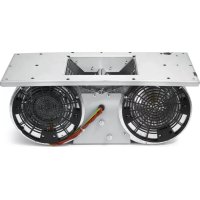
| Product Type | Retractable down-draft extraction system (ventilation hood) |
| Brand | Jenn-Air |
| Model | JXD7030YS |
| Dimensions (W x D) | 76.2 cm (30 in) x 61 cm (24 in) |
| Electrical Supply | 120 V, 60 Hz, 15 A, single-phase, AC |
| Fan Speeds | 4 speeds (1st to 4th) |
| Venting Type | Rigid metal duct, exterior venting required |
| Recommended Duct Diameter | 6 in (15.2 cm) round or 3 1/4 x 10 in (8.3 x 25.4 cm) rectangular |
| Maximum Vent Length | 35 ft (8.9 m) for 6 in or 3 1/4 x 10 in duct |
| Filter Type | Metal grease filter, dishwasher or hand washable |
| Surface Material | Stainless steel |
| Special Features | Motorized deployment and retraction, safety microswitch for filter, speed slider |
| Installation Options | Bottom, left side or right side venting; island mount possible |
| Maintenance | Clean filters regularly; stainless steel surface with soapy water; do not use abrasives |
| Safety | Do not use with solid-state speed control; automatic shutdown if filter improperly installed; disconnect power before servicing |
| Warranty | Limited 2-year warranty |
| Customer Service | 1-800-JENNAIR (1-800-536-6247) or www.jennair.com |
Frequently Asked Questions - JXD7030YS JENN-AIR
User questions about JXD7030YS JENN-AIR
0 question about this device. Answer the ones you know or ask your own.
Ask a new question about this device
Download the instructions for your Range hood in PDF format for free! Find your manual JXD7030YS - JENN-AIR and take your electronic device back in hand. On this page are published all the documents necessary for the use of your device. JXD7030YS by JENN-AIR.
USER MANUAL JXD7030YS JENN-AIR
30" (76.2 CM) AND 36" (91.4 CM) RETRACTABLE (POP-UP) DOWNDRAFT VENT SYSTEM
SYSTÈME DE VENTILATION RÉTRACTABLE (CLAPET) DE 30" (76,2 CM) ET 36" (91,4 CM) - ASPIRATION PAR LE BAS
Installation Instructions and Use & Care Guide
For questions about features, operation/performance, parts, accessories, or service in the U.S.A., call: 1-800-JENNAIR (1-800-536-6247), or visit our website at www.jennair.com.
In Canada, call: 1-800-JENNAIR (1-800-536-6247), or visit our website at www.jennair.ca.
IMPORTANT: READ AND SAVE THESE INSTRUCTIONS.
FOR RESIDENTIAL USE ONLY.
IMPORTANT : LIRE ET CONSERVER CES INSTRUCTIONS.
POUR UTILISATION RÉSIDENTIELLE UNIQUEMENT.

JENN-AIR®
LI3ZVD/W10342490G
TABLE OF CONTENTS TABLE DES MATIÈRES
VENT SYSTEM SAFETY....3
INSTALLATION REQUIREMENTS....5
Tools and Parts....5
Location Requirements....5
Electrical Requirements 8
Venting Requirements....8
INSTALLATION INSTRUCTIONS....9
Venting Methods....9
Install Vent System....10
Rear Mounting — Blower Motor....12
Complete Installation ....14
Make Electrical Connections....16
Check Operation....16
VENT SYSTEM USE....17
Operating Downdraft Vent 17
VENT SYSTEM CARE ....17
Surface of Downdraft Vent....17
Filters....17
TROUBLESHOOTING....18
WIRING DIAGRAM....19
ASSISTANCE OR SERVICE....20
In the U.S.A. 20
In Canada....20
Accessories....20
WARRANTY 21
SÉCURITÉ DU SYSTÈME DE VENTILATION....22
EXIGENCES D'INSTALLATION ....24
INSTRUCTIONS D'INSTALLATION....28
ASSISTANCE OU SERVICE....40
Aux É.-U. 40
Au Canada....40
Accessoires....40
GARANTIE....41
VENT SYSTEM SAFETY
Your safety and the safety of others are very important.
We have provided many important safety messages in this manual and on your appliance. Always read and obey all safety messages.

This is the safety alert symbol.
This symbol alerts you to potential hazards that can kill or hurt you and others.
All safety messages will follow the safety alert symbol and either the word "DANGER" or "WARNING."
These words mean:
! DANGER
You can be killed or seriously injured if you don't immediately follow instructions.
WARNING
You can be killed or seriously injured if you don't follow instructions.
All safety messages will tell you what the potential hazard is, tell you how to reduce the chance of injury, and tell you what can happen if the instructions are not followed.
State of California Proposition 65 Warnings:
WARNING: This product contains one or more chemicals known to the State of California to cause cancer.
WARNING: This product contains one or more chemicals known to the State of California to cause birth defects or other reproductive harm.
IMPORTANT SAFETY INSTRUCTIONS
WARNING: TO REDUCE THE RISK OF FIRE, ELECTRIC SHOCK, OR INJURY TO PERSONS, OBSERVE THE FOLLOWING:
■ Use this unit only in the manner intended by the manufacturer. If you have questions, contact the manufacturer.
■ Before servicing or cleaning the unit, switch power off at service panel and lock the service disconnecting means to prevent power from being switched on accidentally. When the service disconnecting means cannot be locked, securely fasten a prominent warning device, such as a tag, to the service panel.
■ Installation work and electrical wiring must be done by qualified person(s) in accordance with all applicable codes and standards, including fire-rated construction.
■ Do not operate any fan with a damaged cord or plug. Discard fan or return to an authorized service facility for examination and/or repair.
■ Sufficient air is needed for proper combustion and exhausting of gases through the flue (chimney) of fuel burning equipment to prevent backdrafting. Follow the heating equipment manufacturer's guideline and safety standards such as those published by the National Fire Protection Association (NFPA), the American Society for Heating, Refrigeration and Air Conditioning Engineers (ASHRAE), and the local code authorities.
■ When cutting or drilling into wall or ceiling, do not damage electrical wiring and other hidden utilities.
■ Ducted fans must always be vented outdoors.
CAUTION: For general ventilating use only. Do not use to exhaust hazardous or explosive materials and vapors.
CAUTION: To reduce risk of fire and to properly exhaust air, be sure to duct air outside - do not vent exhaust air into spaces within walls or ceilings, attics or into crawl spaces, or garages.
WARNING: TO REDUCE THE RISK OF FIRE, USE ONLY METAL DUCTWORK.
WARNING: TO REDUCE THE RISK OF A RANGE TOP GREASE FIRE:
■ Never leave surface units unattended at high settings. Boilovers cause smoking and greasy spillovers that may ignite. Heat oils slowly on low or medium settings.
■ Always turn hood ON when cooking at high heat or when flambeing food (i.e. Crepes Suzette, Cherries Jubilee, Peppercorn Beef Flambé).
■ Clean ventilating fans frequently. Grease should not be allowed to accumulate on fan or filter.
■ Use proper pan size. Always use cookware appropriate for the size of the surface element.
WARNING: TO REDUCE THE RISK OF INJURY TO PERSONS IN THE EVENT OF A RANGE TOP GREASE FIRE, OBSERVE THE FOLLOWING: ^a
■ SMOTHER FLAMES with a close fitting lid, cookie sheet, or metal tray, then turn off the burner. BE CAREFUL TO PREVENT BURNS. If the flames do not go out immediately, EVACUATE AND CALL THE FIRE DEPARTMENT.
■ NEVER PICK UP A FLAMING PAN - you may be burned.
■ DO NOT USE WATER, including wet dishcloths or towels - a violent steam explosion will result.
■ Use an extinguisher ONLY if:
- You know you have a class ABC extinguisher, and you already know how to operate it.
- The fire is small and contained in the area where it started.
– The fire department is being called. - You can fight the fire with your back to an exit.
^a Based on "Kitchen Fire Safety Tips" published by NFPA.
■ WARNING: To reduce the risk of fire or electrical shock, do not use this fan with any solid-state speed control device.
READ AND SAVE THESE INSTRUCTIONS
INSTALLATION REQUIREMENTS
Tools and Parts
Gather the required tools and parts before starting installation. Read and follow the instructions provided with any tools listed here.
Tools Needed
■Jigsaw or keyhole saw
Drill
■ 18 " (3 mm) drill bit for pilot holes
Pencil
■Tape measure or ruler
■Flat-blade screwdriver
■Phillips screwdriver
■ ^3/_8 " (9.5 mm) nut driver
Level
■Pliers
■Metal snips
■Wire stripper or utility knife
■Caulking gun and weatherproof caulking compound
Parts Supplied
■Top trim – stainless
■End caps (2)
■Lower support legs (2)
■Undercounter mounting brackets (2)
■4 x 8 mm screws (16)
■3.5 x 9.5 mm screws (3)
■3 14 " x 10" (8.3 cm x 25.4 cm) rectangular damper
■4 ^3/_4 " (12.0 cm) motor box
■ ^1/4 " (6.4 mm) deep cover
■Flat vent cover plate
■6" (15.2 cm) diameter vent transition with damper
Parts Needed
■UL listed or CSA approved 12 " (12.7 mm) conduit connector
■Wall or roof cap with damper to match vent system
■Vent system
■Home power supply cable
■UL listed wire connectors (3)
■Vent clamps/duct tape as required
Location Requirements
NOTE: Downdraft vent is installed directly behind the cooktop. Install the downdraft vent first, and then install the cooktop.
IMPORTANT: Observe all governing codes and ordinances.
■Have a qualified technician install the downdraft vent. It is the installer's responsibility to comply with installation clearances specified on the model/serial/rating plate. The model/serial/rating plate is located on the front of the downdraft vent above the terminal box cover.
■Downdraft vent location should be away from strong draft areas, such as windows, doors, and strong heating vents or fans.
■Cabinet opening dimensions that are shown must be used. Given dimensions provide minimum clearance.
■Consult the cooktop manufacturer installation instructions before making any cutouts.
Check that the downdraft vent and cooktop location will clear the cabinet walls, backsplash, and rear wall studs inside the cabinet.
Check for the minimum distance between the front edge of the countertop and the front edge of the cooktop. The minimum horizontal distance between the overhead cabinets is the same as the width of the installed downdraft vent.
■All openings in ceiling and wall where the downdraft vent will be installed must be sealed.
■Grounded electrical outlet is required. See the “Electrical Requirements” section.
■When installing the downdraft vent, the cabinet drawer will need to be removed and the drawer front installed permanently to the cabinet.
Cabinet Construction:
Downdraft vent is designed for use in a cabinet with a depth of 24" (61 cm). Some installations require a countertop deeper than 25" (63.5 cm). See the "Countertop Cutout Dimensions" section.
The maximum depth of the overhead cabinet is 13" (33 cm). Overhead cabinets installed at either side of the downdraft vent must be 18" (45.7 cm) above the cooking surface.
For Mobile Home Installations
The installation of this downdraft vent must conform to the Manufactured Home Construction Safety Standards, Title 24 CFR, Part 328 (formerly the Federal Standard for Mobile Home Construction and Safety, title 24, HUD, Part 280) or when such standard is not applicable, the standard for Manufactured Home Installation 1982 (Manufactured Home Sites, Communities and Setups) ANSI A225.1/NFPA 501A, or latest edition, or with local codes.
Product Dimensions

As-Received Blower

Reversed Blower
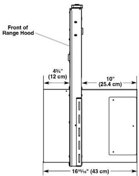
Cabinet Dimensions

NOTES:
■See cooktop manufacturer's instructions for cooktop cutout depth and width.
■Use dimensions for vent system cutout location that applies to your installation.
■Interior-mounted blower systems connect with 3^1/4 " x 10" (8.3 cm x 25.4 cm) rectangular or 6" (15.2 cm) round vent system. The cutout locations for this vent system will depend on your specific installation.
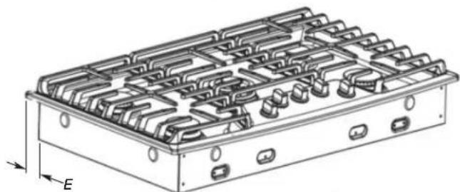
Countertop Cutout Dimensions
IMPORTANT: Countertops with a bull-nosed front edge are not recommended for these installations.
Some models require a countertop deeper than 25" (63.5 cm); see the following illustrations.
To avoid mistakes, it is recommended that the cooktop and vent cutouts be drawn on the countertop before making any cutouts. See the Installation Instructions that came with your cooktop for complete cutout dimensions, location dimensions, and installation details.

A. Downdraft vent
E. 1^13/_16 (46.2 mm)
B. Cooktop
F. 1/2" (12.7 mm) minimum
C. Measurement of cooktop rear overhang
G. ¼" (6.4 mm) minimum
D. D = Measurement of cooktop rear overhang (C) + 1 ^13 /16" (46.2 mm) (E)
H. Countertop and backsplash
1. 12 " (12.7 mm) minimum

natural_image
Technical line drawing of a multi-chamber electric motor housing with mounting ports and internal grid structure (no text or symbols)A. 12 " (12.7 mm) minimum to backsplash or rear wall
B. ^3/_4 (19.1 mm) maximum backsplash depth
C. 27 ^1/2 " (69.9 cm) on 30" (76.2 cm) models 33 ^1/2 " (85.9 cm) on 36" (91.4 cm) models
D. D = E + 1^13 / 16'' (46.2 mm)
E. Cooktop rear overhang
Electrical Requirements
Observe all governing codes and ordinances.
Ensure that the electrical installation is adequate and in conformance with National Electrical Code, ANSI/NFPA 70 (latest edition) or CSA Standards C22.1-94, Canadian Electrical Code, Part 1 and C22.2 No. 0-M91 (latest edition) and all local codes and ordinances.
If codes permit and a separate ground wire is used, it is recommended that a qualified electrician determine that the ground path is adequate.
A copy of the above code standards can be obtained from:
National Fire Protection Association
1 Batterymarch Park
Quincy, MA 02169-7471
CSA International
8501 East Pleasant Valley Road
Cleveland, OH 44131-5575
■A 120-volt, 60 Hz., AC-only, 15-amp, fused electrical circuit is required.
■If the house has aluminum wiring, follow the procedure below:
- Connect a section of solid copper wire to the pigtail leads.
- Connect the aluminum wiring to the added section of copper wire using special connectors and/or tools designed and UL listed for joining copper to aluminum.
Follow the electrical connector manufacturer's recommended procedure. Aluminum/copper connection must conform with local codes and industry accepted wiring practices.
■Wire sizes and connections must conform with the rating of the appliance as specified on the model/serial/rating plate. The model/serial/rating plate is located on the front of the downdraft vent above the wiring box cover.
■Wire sizes must conform to the requirements of the National Electrical Code, ANSI/NFPA 70 (latest edition) or CSA Standards C22. 1-94, Canadian Electrical Code, Part 1 and C22.2 No. 0-M91 (latest edition) and all local codes and ordinances.
Venting Requirements
IMPORTANT: Make sure there is proper clearance within the wall or floor before making exhaust vent cutouts.
■Use heavy (rigid) metal vent.
■Venting system must terminate to the outside.
■Do not terminate the vent system in an attic or other enclosed area.
■Do not use 4" (10.2 cm) laundry-type wall caps.
■Do not install 2 elbows together.
■Do not use plastic or metal foil vent.
■The length of vent system and number of elbows should be kept to a minimum to provide efficient performance.
■Use no more than three 90° elbows.
■ Make sure there is a minimum of 24" (61 cm) of straight vent between the elbows if more than one elbow is used.
■Use clamps or duct tape to seal all joints in the vent system.
■Use caulking tape to seal the exterior wall or floor opening around cap.
■Do not cut joist or stud. If vent cutout falls over a joist or stud, a supporting frame must be constructed.
Flexible metal vent is not recommended. If it is used, calculate each foot of flexible vent as 2 ft (0.6 m) of rigid metal vent.
Flexible elbows count twice as much as standard elbows.
Recommended vent system length:
For either interior-mounted or exterior-mounted blower installations, the vent system length should not exceed the maximum lengths listed in the "Maximum Length of Vent System" chart. See "Calculating Vent System Length" in the "Venting Methods" section in the Installation Instructions.
Cold Weather Installations
An additional backdraft damper should be installed to minimize backward cold airflow and a thermal break should be installed to minimize conduction of outside temperatures as part of the vent system. The damper should be on the cold air side of the thermal break.
The break should be as close as possible to where the vent system enters the heated portion of the house.
Makeup Air
Local building codes may require the use of makeup air systems when using ventilation systems greater than specified CFM of air movement. The specified CFM varies from locale to locale. Consult your HVAC professional for specific requirements in your area.
INSTALLATION INSTRUCTIONS
Venting Methods
Determine which venting method is best for your application. Vent system can terminate either through the wall or floor.
Island Location

A. Down vent
NOTE: For island locations, a front- or rear-mounted blower motor can also be mounted for right or left venting if needed for your application. Most island applications would still require the venting to be directed down through the floor.
Built-In Cabinet Location
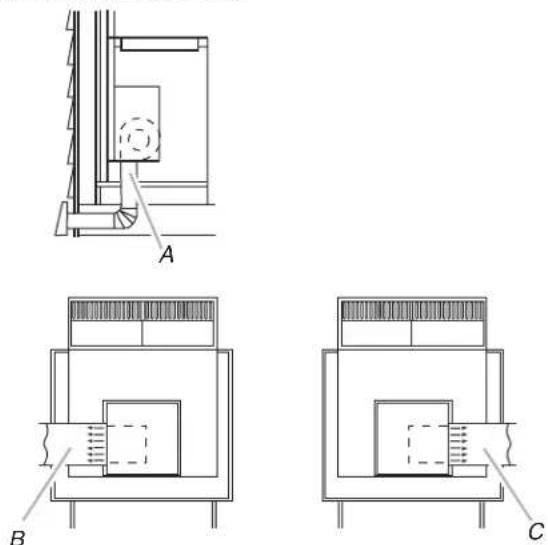
A. Down vent
B. Left vent
C. Right vent
Island Location — Vent System Installed Under a Concrete Slab Using PVC Sewer Pipe Front-Mounted Blower Motor (Standard)

Rear-Mounted Blower Motor
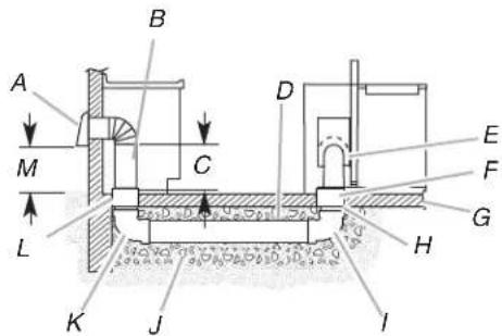
A. Wall cap
B. 6" (15.2 cm) round metal vent
C. 16" (40.6 cm) maximum
D. 6" (15.2 cm) round PVC sewer pipe
E. 6" (15.2 cm) round metal vent transition with damper (supplied)
F. 6" (15.2 cm) round PVC coupling
G. Concrete slab
H. 6" (15.2 cm) round PVC sewer pipe
I. 6" (15.2 cm) round 90° PVC sewer pipe elbow
J. Tightly pack gravel or sand completely around pipe.
K. 6" (15.2 cm) round 90° PVC sewer pipe elbow
L. 6" (15.2 cm) round PVC coupling
M. 12" (30.5 cm) minimum
Calculating Vent System Length
3¼" x 10" (8.3 cm x 25.4 cm) rectangular vent is required from the blower motor box. It can be transitioned to 6" (15.2 cm) round vent if needed.
Maximum Length of Vent System
Vent Length
| 6" (15.2 cm) round 35 ft (8.9 m) |
| 31/4" x 10" (8.3 cm x 25.4 cm) 35 ft (8.9 m) |
To calculate the length of the system you need, add the equivalent feet (meters) for each vent piece used in the system.
| Vent Piece | 31/4" x 10" (8.3 cm x 25.4 cm) Rectangular | |
| 31/4" x 10" (8.3 cm x 25.4 cm)90° elbow | 5.0 ft(1.5 m) |  |
| 31/4" x 10" (8.3 cm x 25.4 cm) flat elbow | 12.0 ft(3.7 m) |  |
| 31/4" x 10" (8.3 cm x 25.4 cm) wall cap | 0.0 ft(0.0 m) | 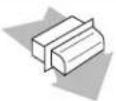 |
| Vent Piece 6" (15.2 cm) Round | ||
| 45° elbow 2.5 ft | (0.8 m) |  |
| 90° elbow 5.0 ft | (1.5 m) |  |
| 6" (15.2 cm) wall cap 0.0 ft | (0.0 m) |  |
| 31/4" x 10" (8.3 cm x 25.4 cm) to 6" (15.2 cm) transition | 4.5 ft(1.4 m) |  |
| 6" (15.2 cm) to 31/4" x 10"(8.3 cm x 25.4 cm) transition | 1 ft(0.3 m) | 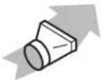 |
| 31/4" x 10" (8.3 cm x 25.4 cm) to 6" (15.2 cm) 90° elbow transition | 5.0 ft(1.5 m) | [CX6S] |
| 6" (15.2 cm) to 31/4" x 10"(8.3 cm x 25.4 cm) 90° elbow transition | 5.0 ft(1.5 m) | 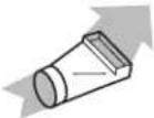 |
Example Vent System
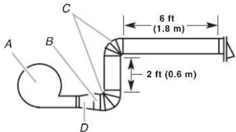
A. Blower motor
B. Transition
C. 90° elbows
D. Backdraft damper
The following example falls within the maximum vent length of 35 ft (8.9 m).
2 - 90° elbow = 10.0 ft (3 m)
1 - wall cap = 0.0 ft (0.0 m)
8 ft (2.4 m) straight = 8.0 ft (2.4 m)
Transition = 4.5 ft (1.4 m)
Length of 6" (15.2 cm) or 3 ^1/4 " x 10" = 22.5 ft (6.8 m)
(8.3 cm x 25.4 cm) system
Install Vent System
WARNING
Excessive Weight Hazard
Use two or more people to move and install downdraft vent.
Failure to do so can result in back or other injury.
- Place cardboard or similar material on top of a flat surface where you can easily assemble the downdraft vent system.
- Remove parts packages, downdraft vent, and blower box from the carton.
- Remove all shipping materials, tape, and film from the downdraft vent and blower box.
- Measure distance "X" from the cabinet floor to the top of the countertop. Subtract 28^1/2 " (72.4 cm) from distance "X" to determine dimension "Y" ( X - 28^1/2 = Y ).

- Attach the support legs to the side of the vent box with 4 - 4 x 8 mm screws in each support leg. Adjust to dimension "Y" from the bottom of the vent box to the bottom of the support legs. Tighten screws.

A. Motor box
B. Support leg
C. 4 x 8 mm screws (4)
Determine Which Vent Direction Is Best for Your Installation
When installed in a cabinet, vent system can exhaust through the bottom, left, or right of the cabinet.
IMPORTANT: When using the 6" (15.2 cm) vent transition (supplied) for 6" round venting, only left or right venting is recommended.
Bottom Venting:
NOTE: If installing the vent damper in the down position, a wall or roof cap with a damper at the exit end of the vent system is required.
■Downdraft vent is shipped with blower in down-venting position, so no modification is required.
■If rear mounting of the blower motor is not required, go to the "Complete Installation" section.
■To mount the blower motor to the rear side of the vent box, go to the "Rear Mounting — Blower Motor" section.
Left or Right Venting:
-
Using 2 or more people, place the downdraft vent system on its back.
-
Remove the 4 screws from the cover plate mounted to the face of the motor box and set them aside.

A. Cover plate
D. Motor mounting screws (4)
B. Cover plate screws (4)
E. Vent cover plate
C. Cover plate keyhole slot shoulder screws (4)
F. Motor box
G. Vent cover screws (3)
-
Slide the cover plate up and slip it over the keyhole slot shoulder screws. Set the cover aside.
-
Remove 4 screws from the bottom of the motor box that hold the motor assembly to the motor box.
NOTE: Disconnect the electrical wiring connection from motor if needed.
-
Remove 3 screws and the vent cover plate from the left or right side of the motor box for the venting direction to be used.
-
Rotate the blower motor assembly 90° to the left or right side to the chosen venting direction and secure to the blower box with motor mounting screws previously removed. Do not twist or bind the wires.
-
Install the vent cover plate over the rectangular opening in the bottom of the motor box and secure with vent cover screws.
NOTE: Reinstall the electrical wiring connection to motor if removed.
-
Reinstall the cover plate to the face of the motor box and secure with 4 cover plate screws previously removed.
-
For mounting the blower motor to the back of the vent box, go to the "Rear Mounting — Blower Motor" section. Otherwise, go to the "Complete Installation" section.
Rear Mounting — Blower Motor
NOTE: Optional blower motor rear-mounting position (opposite side) for island cabinet location. The blower motor box assembly can be moved to the opposite side (rear) of the vent box.
- Remove 7 screws from the mounting flanges of the blower motor box.
Front View
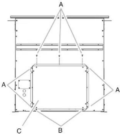
A. Screws (7)
B. Keyhole slot shoulder screws (2)
C. Blower motor box

natural_image
Technical line drawing of a mechanical assembly with a box and panel, showing no text or symbols.A. Blower motor box
- Lift blower motor box off the shoulder screws in the keyhole slots. Disconnect wire connection from blower motor and set blower motor box aside.
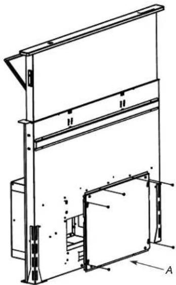
- Remove 6 screws from the mounting flange of the 14'' (6.4 mm) deep cover.
Rear View

natural_image
Pure technical diagram of a structural frame with labeled points A, B, C and internal components (no text or symbols beyond labels)A. Screws (6)
B. Keyhole slot shoulder screws (2)
C. 1/4" (6.4 mm) deep cover
natural_image
Technical line drawing of a mechanical assembly with no visible text or symbolsA. Deep cover
- Lift the 14 " (6.4 mm) deep cover off the shoulder screws in the keyhole slots and set the cover aside.
- Remove the screws from the wire-mounting plate.

A. Screws
B. Wire-mounting plate
C. Blower motor box
- Hold the wire-mounting plate and push the grommet out of the wire-mounting plate.

natural_image
Pure mechanical diagram showing a lever and mounting points (no text or symbols)A. Wire-mounting plate
B. Grommet
- Slide the wire assembly through the slot in the wire-mounting plate to remove it.
- Place the wire assembly through the opening to the opposite side of the vent box.
- Reassemble the wire assembly and grommet to the wire-mounting plate.
- Install the wire-mounting plate to the vent box using the 4 screws previously removed.
- Place the blower motor box assembly with the keyhole slots over the 2 shoulder screws on the rear of the vent box and reconnect the wire connection to the blower motor.
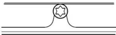
- Mount the blower motor box to the vent box and secure using the 6 screws previously removed.
natural_image
Pure geometric diagram with concentric lines and a central star-like symbol (no text or labels)-
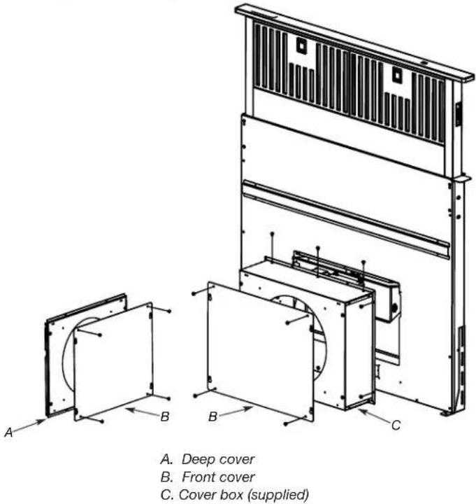
Mount the 4^3/4 " (12.0 cm) cover box (supplied) to the front of the vent box. Place the keyhole slots over the 2 shoulder screws, align the mounting holes, and secure the cover box to vent box using the 6 screws previously removed from the 1/4 " (6.4 mm) deep cover.
-
Remove the front cover from the deep cover, place the front cover over the previously mounted cover box, and secure using the 4 screws previously removed.
- Go to the "Complete Installation" section.
Complete Installation
NOTE: The downdraft vent system is supplied with a 3^1/4 " x 10" (8.3 cm x 25.4 cm) backdraft damper and a 6" (15.2 cm) round vent transition with damper. Refer to "3 ^1/4 " x 10" (8.3 cm x 25.4 cm) Backdraft Damper" or "6" (15.2 cm) Round Vent Transition with Damper," depending upon the type of venting you are using.
3^1/4 x 10" (8.3 cm x 25.4 cm) Backdraft Damper
- Attach the 3 ^1/4 " x 10" (8.3 cm x 25.4 cm) backdraft damper to the vent opening in the blower motor box, using three 3.5 x 9.5 mm screws.

A. 3.5 x 9.5 mm screws
B. 3¼" x 10" (8.3 cm x 25.4 cm) backdraft damper
6" (15.2 cm) Round Vent Transition with Damper
- Attach the 6" (15.2 cm) round vent transition to vent opening (left- or right-side venting only is recommended), using two 3.5 x 9.5 mm screws.
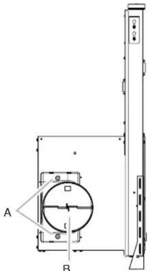
A. 3.5 x 9.5 mm screws
B. 6" (15.2 cm) round vent transition with damper
- Remove 4 screws attaching the terminal box cover.

natural_image
Technical diagram of a mechanical assembly with concentric components and mounting brackets (no text or symbols)A. Terminal box cover
-
Determine which direction (front or rear) the home power supply cable will enter the terminal box. Remove the appropriate knockout from the front or rear panel and install a 12 " (12.7 mm) UL listed or CSA approved conduit connector.
-
Using 2 or more people, insert the downdraft vent into the countertop cutout. Position downdraft vent so it is centered in the cutout with the rear flange over the edge of the cutout and the rear of the vent box against the edge of the cutout.

A. Rear flange of downdraft vent
E. Lower support leg
B. Edge of cutout in countertop
F. Cabinet floor
C. Rear of downdraft vent
G. Countertop
D. Cabinet back
- Install the left and right undercounter mounting brackets to the vent box. Slide the keyhole slots over the guide tabs and push the brackets up to set them in place.

A. Vent box
B. Undercounter mounting bracket
C. Keyhole slots
D. Guide tabs
- Drill 2 pilot holes through each of the undercounter mounting brackets into the underside of the countertop. Using 2 screws (not provided) of the appropriate length, mount the brackets to the countertop.
IMPORTANT: Select a screw length that will not allow the screws to go through the countertop when tightened.
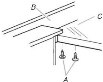
A. Screws
B. Backsplash
C. Countertop
- Check that the downdraft vent is level as shown below. Loosen the lower support leg screws and position the legs against the cabinet floor.

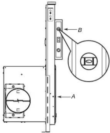
A. Downdraft
B. Level
- Fasten the lower support legs to the cabinet floor with screws (not provided).
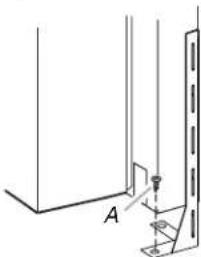
natural_image
Pure technical line drawing of a mechanical assembly without any text, numbers, or symbolsA. Screw (not provided)
- Tighten the lower support legs screws.
- Attach the left and right end caps to the vent box. Place the tab into the mounting slot at each end of the downdraft vent, as shown, and push down to lock into place.
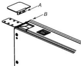
A. End cap tab
B. Mounting slot
Make Electrical Connections
WARNING

Electrical Shock Hazard
Disconnect power before servicing.
Replace all parts and panels before operating.
Failure to do so can result in death or electrical shock.
- Disconnect power.
- Feed the power supply cable through the conduit connector and into the terminal box.
WARNING

Electrical Shock Hazard
Electrically ground blower.
Connect ground wire to green and yellow ground wire in terminal box.
Failure to do so can result in death or electrical shock.
- Connect the green (or green/yellow) ground wire to the green or yellow/green ground wire using UL listed wire connectors. Tighten the screw on the conduit connector.
- Connect the 2 white wires together using UL listed wire connectors.
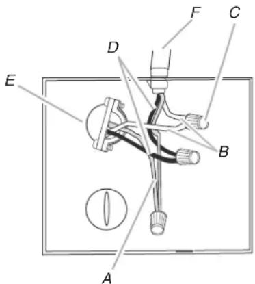
A. Green or green and yellow ground wire
B. White wires
C. UL listed wire connectors
D. Black wires
E. UL listed or CSA approved conduit connector
F. Downdraft vent wiring
- Connect the 2 black wires together using UL listed wire connectors.
- Replace the terminal box cover and secure with screw.
- Reconnect power.
Check Operation
- Push and hold the button on the top of the downdraft vent for a few seconds. The retractable section of the downdraft vent will rise and the blower will be able to start using the control slider. Remove any protective film and use a stainless steel cleaner to clean any remaining grease. Position the top trim over the retractable section and snap trim into place.
Trim kits for matching your cooktop color are available from your dealer.
For information on ordering, see the "Assistance or Service" section.
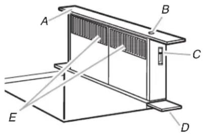
A. Top trim
B. On/Off button
C. Blower control slider
D. End cap
E. Filters
- Slide the control slider on the side of vent to check the operation and speed of the blower.
- If the blower does not operate:
■Check that filter or filters are pressed in as far as they will go.
■Check that the circuit breaker has not tripped or a household fuse blown.
- Connect vent system to blower. Vent system must end with a wall or roof cap. Use clamps or duct tape to seal all joints.
- Install cooktop according to manufacturer's instructions. Check that rear of cooktop overlaps edge of retractable downdraft vent by 3/8" (9.5 mm). See "Countertop Cutout Dimensions" in the "Location Requirements" section.
NOTE: To get the most-efficient use from your new retractable downdraft vent, read the "Vent System Use" section.
VENT SYSTEM USE
The retractable downdraft vent system is designed to remove smoke, cooking vapors, and odors from the cooktop area.
■For best results, the vent should be operating before cooking is started.
■ If you use large or tall utensils, place them on the large rear element or burner surface.
■A higher heat setting than normally used may be needed when the downdraft vent is operating.
■For gas cooktops, the downdraft vent system may affect the flame stability and cooking performance. To improve the burner performance, either decrease the downdraft vent blower speed or increase the cooktop burner flame setting.
For gas cooktops with flame-sensing ignitions, the downdraft vent system may disperse the flame away from the spark igniter and may cause it to continually spark while trying to reignite a burner that is already lit. To resolve the issue of the cooktop igniter continuously sparking, either decrease the downdraft vent blower speed or increase the cooktop flame setting for that burner.
Operating Downdraft Vent
To Use:
- Push and hold the button on top of downdraft vent for a few seconds. (This slight delay helps avoid unintentional raising of the vent during cleaning of the cooktop area.) Retractable section of downdraft vent will rise. Blower will begin to vent immediately if blower control knob slider is set to an On position.
- Slide the control slider on the right-hand side of the downdraft vent to adjust the blower motor speed.
When Cooking Is Complete:
- Push the button on top of the retractable downdraft vent. The blower will turn off and the retractable section of the vent will return to the closed position.
NOTE: If a spill occurs on the cooktop that allows liquids to seep inside the downdraft vent, you must turn the downdraft vent off immediately. It is possible to cause damage to the downdraft vent if water is allowed inside the downdraft vent while it is operating.
- Immediately turn off the downdraft vent at the speed control located on the right-hand side of the downdraft vent.
- Turn off the power supply to the downdraft vent at the circuit breaker box or fuse box.
- Allow plenty of time for the downdraft vent to dry naturally. Do not open the downdraft vent to remove the water.
VENT SYSTEM CARE
Surface of Downdraft Vent
To avoid damaging the finish, clean downdraft vent with soap and water. Do not use scouring powder or abrasive solutions.
Exterior Surfaces:
To avoid damage to the exterior surface, do not use steel wool or soap-filled scouring pads.
Always wipe dry to avoid watermarks.
Cleaning Method:
■Liquid detergent soap and water or all-purpose cleanser.
■Wipe with damp soft cloth or nonabrasive sponge, and then rinse with clean water and wipe dry.
NOTE: To avoid damage, do not soak cloth or sponge.
Filters
Frequently remove and clean the filter(s) in the retractable section of the downdraft vent. This will improve the operating efficiency of the downdraft vent system.
To Replace:
- Remove each filter by pulling the spring release handle and then pulling down the filter.
- Wash metal filters as needed in dishwasher or hot detergent solution.
- Reinstall the filter by making sure the spring release handles are toward the front. Insert metal grease filter into upper track.
- Pull the spring release handle down.
- Push up on metal filter and release handle to latch into place.
- Repeat steps 1 through 5 for the other filter.
To Clean:
- Remove the filter(s) and clean them in a dishwasher or in a hot detergent solution. The downdraft vent will not operate when the filters are not in place.
- Dry the clean filter(s) and reinstall, making sure that they lock into place.
If Retractable Downdraft Vent Does Not Operate After Clean Filters Have Been Installed:
Push the filter in as far as it will go. When the filter is removed, the microswitch behind the filter is deactivated. This feature will not allow the vent system to operate until the filter is properly installed.
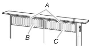
A. Spring-release handles
B. Left metal filter
C. Right metal filter
TROUBLESHOOTING
First try the solutions suggested here. If you need further assistance or more recommendations that may help you avoid a service call, refer to the warranty page in this manual and scan the code there with your mobile device or visit https://jennair.custhelp.com.
In Canada, visit http://www.jennair.ca.
Contact us by mail with any questions or concerns at the address below:
In the U.S.A.:
In Canada:
Jenn-Air Brand Home Appliances
Customer eXperience Center
553 Benson Road
Benton Harbor, MI 49022-2692
Jenn-Air Brand Home Appliances
Customer eXperience Centre
200 - 6750 Century Ave.
Mississauga, Ontario L5N 0B7
Please include a daytime phone number in your correspondence.
| PROBLEM POSSIBLE CAUSES AND/OR SOLUTIONS | |
| Nothing will operate | Has a household fuse been blown or has a circuit breaker tripped? Replace the fuse or reset the circuit breaker. If the problem continues, call an electrician.Are the filters not seating in the plenum? Make sure the filters are fully depressing the filter switches.Has the Start button been pressed for at least 3 seconds? Push and hold the button on the top of the downdraft vent for at least 3 seconds to complete the cycle needed to start retracting. |
| Vent does not retract | Are the filters in place on downdraft vent? When the filters are removed, the microswitch behind the filter is deactivated. This feature will not allow the vent system to operate until the filter is properly installed.Are the filters installed correctly? Push the filter in as far as it will go to activate the microswitch behind the filter.Has the Start button been pressed for at least 3 seconds? Push and hold the button on the top of the downdraft vent for at least 3 seconds to complete the cycle needed to start retracting.Is the downdraft correctly secured? Make sure that the vent hood is level and upright. Check it is securely fastened to the floor and the counter top. |
| Vent partially raises | Has an obstruction been interfering with the vent movement? Ensure the cooktop is not interfering with the downdraft vent movement.Is the vent level? Level the vent. See the “Install Vent System” section. |
| Blower does not operate | Is the vent fully raised? Check that the vent is totally in the up position.Are the filters installed correctly? Push the filter in as far as it will go to activate the switch behind the filter.Has the control slider been moved from the Off position? Slide the control slider on the right-hand side of the downdraft vent to adjust the blower motor speed.Is the blower installed correctly? See the “Rear Mounting – Blower Motor” section. |
| Downdraft not level on countertop | Is the vent level? Level the vent. See the “Install Vent System” section.Is the vent rising more in one side? Make sure both of the support legs have the same height from the bottom of the vent box to the bottom of the support legs. See the “Install Vent System” section. |
| Vent making noises | Was the vent recently installed and making grinding noises? Use stainless steel cleaner to remove any residue left by the white protective film. Ensure nothing is blocking path of vent.Is there noise due to moving air? Ensure the installation of the product is fully into the cutout and no gap in the middle of it. |
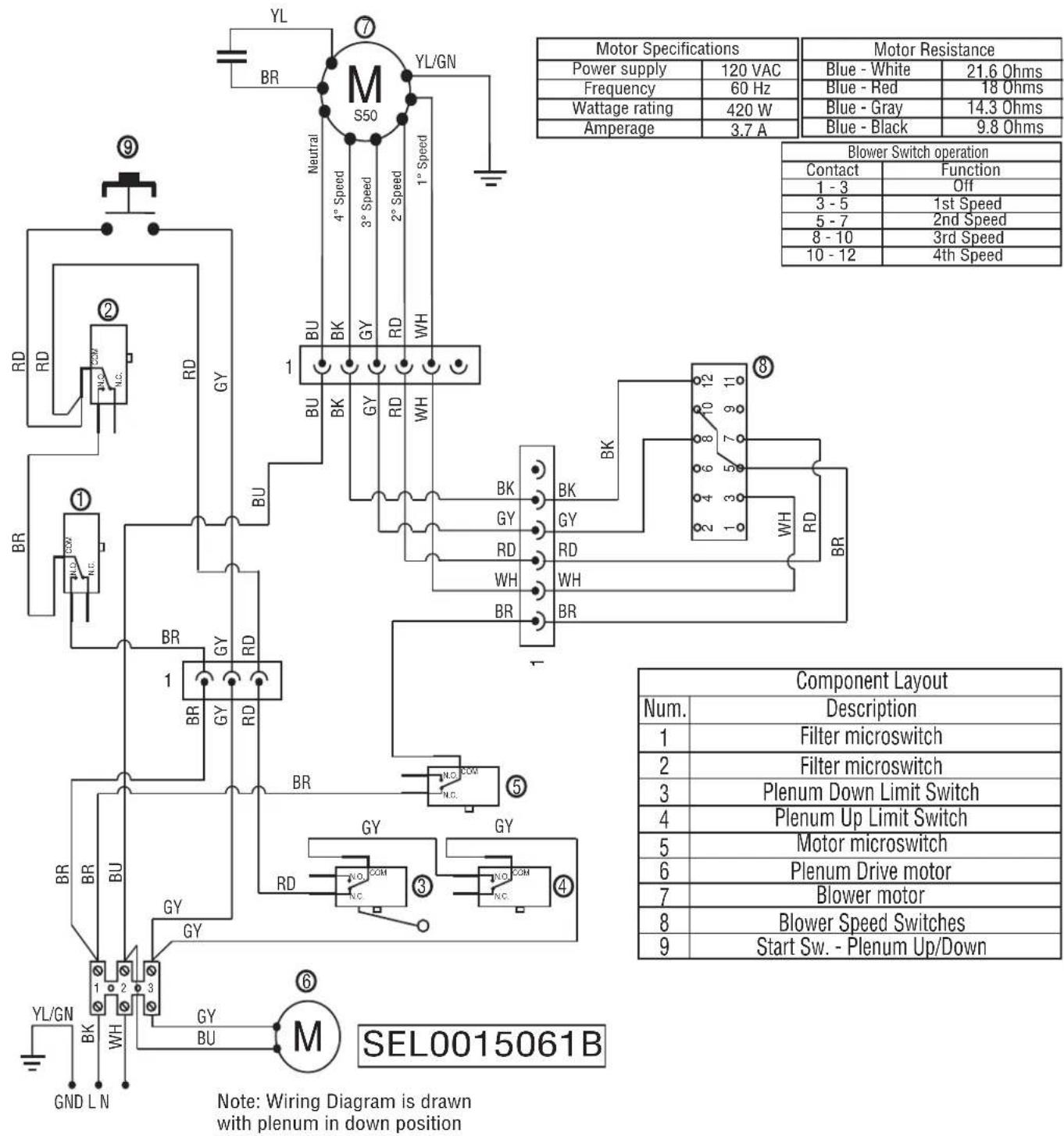
WIRING DIAGRAM
ASSISTANCE OR SERVICE
If you need service
Please refer to the warranty page in this manual.
If you need replacement parts
If you need to order replacement parts, we recommend that you use only factory specified parts. Factory specified parts will fit right and work right because they are made with the same precision used to build every new appliance.
To locate factory specified replacement parts in your area, call the following customer assistance telephone number or your nearest designated service center.
In the U.S.A.
Call Jenn-Air Customer eXperience Center toll-free:
1-800-JENNAIR (1-800-536-6247) or visit our website at www.jennair.com.
Our consultants provide assistance with:
■Scheduling of service. Jenn-Air ^® appliances designated service technicians are trained to fulfill the product warranty and provide after-warranty service anywhere in the United States.
■Features and specifications on our full line of appliances.
■Referrals to local Jenn-Air ^® appliance dealers.
■Installation information.
■Use and maintenance procedures.
■Accessory and repair parts sales.
■Specialized customer assistance (Spanish-speaking, hearing-impaired, limited vision, etc.).
For further assistance
If you need further assistance, you can write to Jenn-Air®
Appliances with any questions or concerns at:
Jenn-Air Brand Home Appliances
Customer eXperience Center
553 Benson Road
Benton Harbor, MI 49022-2692
Please include a daytime phone number in your correspondence.
In Canada
Call the Whirlpool Canada LP Customer eXperience Centre toll-free at 1-800-JENNAIR (1-800-536-6247) or visit our website at www.jennair.ca.
Our consultants provide assistance with:
■Scheduling of service. Jenn-Air ^® appliances designated service technicians are trained to fulfill the product warranty and provide after-warranty service anywhere in Canada.
■Features and specifications on our full line of appliances.
■Referrals to local Jenn-Air ^® appliance dealers.
■Installation information.
■Use and maintenance procedures.
■Accessory and repair parts sales.
For further assistance
If you need further assistance, you can write to Jenn-Air®
Appliances with any questions or concerns at:
Jenn-Air Brand Home Appliances
Customer eXperience Centre
200 - 6750 Century Ave.
Mississauga, Ontario L5N 0B7
Please include a daytime phone number in your correspondence.
Accessories
NOTE: Instructions are included with each kit.
For model series JXD7030Y
30" (76.2 cm) one-piece top trim
Order Part Number W10387676 (black)
For model series JXD7036Y
36" (91.4 cm) one-piece top trim
Order Part Number W10387677 (black)
JENN-AIR® MAJOR APPLIANCE LIMITED WARRANTY
ATTACH YOUR RECEIPT HERE. PROOF OF PURCHASE IS REQUIRED TO OBTAIN WARRANTY SERVICE.
Please have the following information available when you call the Customer eXperience Center:
■Name, address and telephone number
■Model number and serial number
■A clear, detailed description of the problem
■ Proof of purchase including dealer or retailer name and address
IF YOU NEED SERVICE:
- Before contacting us to arrange service, please determine whether your product requires repair. Some questions can be addressed without service. Please take a few minutes to review the Troubleshooting or Problem Solver section of the Use and Care Guide, scan the QR code on the right to access additional resources, or visit https://jennair.custhelp.com.
- All warranty service is provided exclusively by our authorized Jenn-Air Service Providers. In the U.S. and Canada, direct all requests for warranty service to:
Jenn-Air Customer eXperience Center
1-800-JENNAIR (1-800-536-6247).

https://jennair.custhelp.com
If outside the 50 United States or Canada, contact your authorized Jenn-Air dealer to determine whether another warranty applies.
TWO YEAR LIMITED WARRANTY
WHAT IS COVERED WHAT IS NOT COVERED
For two years from the date of purchase, when this major appliance is installed, operated and maintained according to instructions attached to or furnished with the product, Jenn-Air brand of Whirlpool Corporation or Whirlpool Canada LP (hereafter “Jenn-Air”) will pay for Factory Specified Replacement Parts and repair labor to correct defects in materials or workmanship that existed when this major appliance was purchased, or at its sole discretion replace the product. In the event of product replacement, your appliance will be warranted for the remaining term of the original unit’s warranty period.
YOUR SOLE AND EXCLUSIVE REMEDY UNDER THIS LIMITED WARRANTY SHALL BE PRODUCT REPAIR AS PROVIDED HEREIN. Service must be provided by a Jenn-Air designated service company. This limited warranty is valid only in the United States or Canada and applies only when the major appliance is used in the country in which it was purchased. This limited warranty is effective from the date of original consumer purchase. Proof of original purchase date is required to obtain service under this limited warranty.
- Commercial, non-residential, multiple-family use, or use inconsistent with published user, operator or installation instructions.
- In-home instruction on how to use your product.
- Service to correct improper product maintenance or installation, installation not in accordance with electrical or plumbing codes or correction of household electrical or plumbing (i.e. house wiring, fuses or water inlet hoses).
- Consumable parts (i.e. light bulbs, batteries, air or water filters, preservation solutions, etc.).
- Defects or damage caused by the use of non-genuine Jenn-Air parts or accessories.
- Conversion of products from natural gas or L.P. gas.
- Damage from accident, misuse, abuse, fire, floods, acts of God or use with products not approved by Jenn-Air.
- Repairs to parts or systems to correct product damage or defects caused by unauthorized service, alteration or modification of the appliance.
- Cosmetic damage including scratches, dents, chips, and other damage to the appliance finishes unless such damage results from defects in materials and workmanship and is reported to Jenn-Air within 30 days.
- Discoloration, rust or oxidation of surfaces resulting from caustic or corrosive environments including but not limited to high salt concentrations, high moisture or humidity or exposure to chemicals.
- Food or medicine loss due to product failure.
- Pick-up or delivery. This product is intended for in-home repair.
- Travel or transportation expenses for service in remote locations where an authorized Jenn-Air servicer is not available.
- Removal or reinstallation of inaccessible appliances or built-in fixtures (i.e. trim, decorative panels, flooring, cabinetry, islands, countertops, drywall, etc.) that interfere with servicing, removal or replacement of the product.
- Service or parts for appliances with original model/serial numbers removed, altered or not easily determined.
The cost of repair or replacement under these excluded circumstances shall be borne by the customer.
DISCLAIMER OF IMPLIED WARRANTIES
IMPLIED WARRANTIES, INCLUDING ANY IMPLIED WARRANTY OF MERCHANTABILITY OR IMPLIED WARRANTY OF FITNESS FOR A PARTICULAR PURPOSE, ARE LIMITED TO ONE YEAR OR THE SHORTEST PERIOD ALLOWED BY LAW. Some states and provinces do not allow limitations on the duration of implied warranties of merchantability or fitness, so this limitation may not apply to you. This warranty gives you specific legal rights, and you also may have other rights that vary from state to state or province to province.
DISCLAIMER OF REPRESENTATIONS OUTSIDE OF WARRANTY
Jenn-Air makes no representations about the quality, durability, or need for service or repair of this major appliance other than the representations contained in this warranty. If you want a longer or more comprehensive warranty than the limited warranty that comes with this major appliance, you should ask Jenn-Air or your retailer about buying an extended warranty.
LIMITATION OF REMEDIES; EXCLUSION OF INCIDENTAL AND CONSEQUENTIAL DAMAGES
YOUR SOLE AND EXCLUSIVE REMEDY UNDER THIS LIMITED WARRANTY SHALL BE PRODUCT REPAIR AS PROVIDED HEREIN. JENN-AIR SHALL NOT BE LIABLE FOR INCIDENTAL OR CONSEQUENTIAL DAMAGES. Some states and provinces do not allow the exclusion or limitation of incidental or consequential damages, so these limitations and exclusions may not apply to you. This warranty gives you specific legal rights, and you also may have other rights that vary from state to state or province to province.
SÉCURITÉ DU SYSTÈME DE VENTILATION
National Fire Protection Association
1 Batterymarch Park
Quincy, MA 02169-7471
CSA International
8501 East Pleasant Valley Road
Cleveland, OH 44131-5575
natural_image
Technical line drawing of a mechanical assembly with a labeled component 'A' (no text or symbols present)
natural_image
Technical line drawing of a mechanical assembly with no visible text or symbolsD. Clapet anti-retour
natural_image
Technical line drawing of a mechanical assembly with a base and panel, showing no text or symbols.natural_image
Technical line drawing of a structural frame with mounting brackets and internal components (no text or symbols)natural_image
Pure mechanical diagram showing a rectangular frame with four circular holes and a curved pipe or rod, labeled A and B (no text or symbols beyond labels)natural_image
Pure geometric diagram with two parallel lines and a central star-like symbol (no text or labels)natural_image
Technical diagram of a mechanical assembly with concentric components and mounting brackets (no text or symbols)natural_image
Simple line drawing of a vertical structure with a labeled point A, no text or symbols presentA. Encoche d'embout
B. Encoche de montage
Customer eXperience Centre
200 - 6750 Century Ave.
Mississauga, Ontario L5N 0B7
ASSISTANCE OU SERVICE
Customer eXperience Centre
200 - 6750 Century Ave.
Mississauga, Ontario L5N 0B7

https://www.jennair.ca
- 30" (76.2 CM) AND 36" (91.4 CM) RETRACTABLE (POP-UP) DOWNDRAFT VENT SYSTEM
- Installation Instructions and Use & Care Guide
- TABLE OF CONTENTS TABLE DES MATIÈRES
- VENT SYSTEM SAFETY....3
- INSTALLATION REQUIREMENTS....5
- INSTALLATION INSTRUCTIONS....9
- VENT SYSTEM USE....17
- VENT SYSTEM CARE ....17
- TROUBLESHOOTING....18
- WIRING DIAGRAM....19
- ASSISTANCE OR SERVICE....20
- WARRANTY 21
- SÉCURITÉ DU SYSTÈME DE VENTILATION....22
- EXIGENCES D'INSTALLATION ....24
- INSTRUCTIONS D'INSTALLATION....28
- ASSISTANCE OU SERVICE....40
- GARANTIE....41
- VENT SYSTEM SAFETY
- Your safety and the safety of others are very important.
- ! DANGER
- WARNING
- IMPORTANT SAFETY INSTRUCTIONS
- READ AND SAVE THESE INSTRUCTIONS
- INSTALLATION REQUIREMENTS
- Tools and Parts
- Tools Needed
- Parts Supplied
- Parts Needed
- Location Requirements
- Cabinet Construction:
- For Mobile Home Installations
- Product Dimensions
- Cabinet Dimensions
- NOTES:
- Countertop Cutout Dimensions
- Electrical Requirements
- Venting Requirements
- Recommended vent system length:
- Cold Weather Installations
- Makeup Air
- INSTALLATION INSTRUCTIONS
- Venting Methods
- Calculating Vent System Length
- Maximum Length of Vent System
- Install Vent System
- Determine Which Vent Direction Is Best for Your Installation
- Bottom Venting:
- Left or Right Venting:
- Rear Mounting — Blower Motor
- Complete Installation
- 31/4 x 10" (8.3 cm x 25.4 cm) Backdraft Damper
- 6" (15.2 cm) Round Vent Transition with Damper
- Make Electrical Connections
- Check Operation
- VENT SYSTEM USE
- Operating Downdraft Vent
- To Use:
- When Cooking Is Complete:
- VENT SYSTEM CARE
- Surface of Downdraft Vent
- Exterior Surfaces:
- Cleaning Method:
- Filters
- To Replace:
- To Clean:
- If Retractable Downdraft Vent Does Not Operate After Clean Filters Have Been Installed:
- TROUBLESHOOTING
- ASSISTANCE OR SERVICE
- If you need service
- If you need replacement parts
- In the U.S.A.
- Our consultants provide assistance with:
- For further assistance
- In Canada
- Accessories
- For model series JXD7030Y
- For model series JXD7036Y
- JENN-AIR® MAJOR APPLIANCE LIMITED WARRANTY
- IF YOU NEED SERVICE:
- TWO YEAR LIMITED WARRANTY
- WHAT IS COVERED WHAT IS NOT COVERED
- DISCLAIMER OF IMPLIED WARRANTIES
- DISCLAIMER OF REPRESENTATIONS OUTSIDE OF WARRANTY
- LIMITATION OF REMEDIES; EXCLUSION OF INCIDENTAL AND CONSEQUENTIAL DAMAGES
- SÉCURITÉ DU SYSTÈME DE VENTILATION
- ASSISTANCE OU SERVICE
Brand : JENN-AIR
Model : JXD7030YS
Category : Range hood