
CD500 - Mill BLACK & DECKER - Free user manual and instructions
Find the device manual for free CD500 BLACK & DECKER in PDF.


| Product Type | Coffee & Spice Grinder |
| Brand | Black & Decker |
| Model | CD500 |
| Power | 150 W |
| Capacity | 70 g (2.5 oz) |
| Material | Stainless steel blades, plastic body |
| Dimensions (H x W x D) | 18 x 10 x 10 cm (7.1 x 3.9 x 3.9 in) |
| Weight | 0.5 kg (1.1 lb) |
| Voltage | 220-240 V |
| Frequency | 50/60 Hz |
| Safety Features | Safety lock lid, non-slip base |
| Cleaning Method | Wipe with damp cloth; do not immerse in water |
| Warranty | 2 years limited |
| Replacement Parts Available | Yes (lid, bowl, blades) |
| Repairability | User-replaceable blades, professional motor service |
Frequently Asked Questions - CD500 BLACK & DECKER
User questions about CD500 BLACK & DECKER
0 question about this device. Answer the ones you know or ask your own.
Ask a new question about this device
Download the instructions for your Mill in PDF format for free! Find your manual CD500 - BLACK & DECKER and take your electronic device back in hand. On this page are published all the documents necessary for the use of your device. CD500 by BLACK & DECKER.
USER MANUAL CD500 BLACK & DECKER
On the purchase of your Black & Decker small angle grinder.
To ensure the best results from your small angle grinder please read these safety and usage instructions carefully. If you have any questions or queries after reading this manual please do not hesitate to call your local service and information centre (the number is towards the back of this manual).



Contents
Page 4 Safety instructions
Additional safety instructions for small angle grinders
Page 5 Double insulation
Electrical safety
Mains plug replacement
Extension cables
Unwanted tools and the environment
The Black & Decker guarantee
Page 6 After sales service for your Black & Decker product
Our after sales service policy
Accessories
Technical data
Features
Operating your angle grinder
Fitting the wheel guard
Fitting the discs
Page 7 Removing the wheel guard
Fitting abrasive discs
Page 8 Handy hints
Overload
Tool care
Cleaning
EC declaration of conformity
Black & Decker phone numbers and addresses
Guarantee card

Small angle grinder user manual
SAFETY INSTRUCTIONS
Warning! When using electric tools, the following basic safety precautions should always be taken to reduce the risk of fire, electric shock and personal injury. Read all these instructions before attempting to operate this product and save these instructions.
For safe operation:
• We recommend that you take appropriate measures for the protection of hearing if the sound pressure of 85 dB (A) is exceeded.
- Keep the work area clean. Cluttered areas and benches invite injuries.
- Consider work area environment. Do not expose power tools to rain and do not use power tools in damp or wet locations. Keep the work area well lit. Do not use power tools where there is a risk to cause fire or explosion.
- Guard against electric shock. Avoid body contact where possible with earthed or grounded surfaces (e.g. pipes, radiators, ranges, refrigerators).
- Keep children away. Do not let visitors touch the tool or extension cord. All visitors should be kept away from work area.
- Store idle tools. When not in use, tools should be stored in a dry, high or locked place, out of reach of children.
- Do not force the tool. It will do the job better and more safely at the rate for which it was intended.
- Use the right tool. Do not force small tools or attachments to do the job of a heavy duty tool. Do not use tools for purposes not intended; for example, do not use a circular saw to cut tree limbs or logs.
- Dress properly. Do not wear loose clothing or jewellery as they can be caught in moving parts. Rubber gloves and non-skid footwear are recommended when working outdoors. Wear protective hair covering to contain long hair.
- Use safety glasses. Use a face or dust mask as well if the operation is dusty or if using in enclosed spaces.
- Do not abuse the cord. Never carry the tool by its cord or yank it to disconnect it from the socket. Keep the cord away from heat, oil and sharp edges.
- Secure your work. Use clamps or a vice to hold your work. It is safer than using your hand and it frees both hands to operate the tool.
- Do not overreach. Keep proper footing and balance at all times.
- Maintain tools with care. Keep cutting tools sharp and clean for better and safer performance. Follow instructions for lubricating and changing
accessories. Inspect tool cords periodically and if damaged have repaired by an authorised service facility. Inspect extension cords periodically and replace if damaged. Keep handles dry, clean and free from oil and grease.
- Disconnect tools. Disconnect when not in use, before servicing and when changing accessories such as blades, bits and cutters.
- Remove adjusting keys and wrenches. Form the habit of checking to see that keys and adjusting wrenches are removed from the tool and replaced in the storage area before switching on.
- Avoid unintentional starting. Do not carry a plugged-in tool with a finger on the switch. Ensure the switch is off when plugging in.
- Use outdoor extension cords. When a tool is used outdoors, use only extension cords intended for outdoor use and so marked.
- Stay alert. Watch what you are doing. Use common sense. Do not operate tools when you are tired.
- Connect dust extraction equipment. If devices are provided for the connection of dust extraction and collection facilities, ensure these are connected and properly used, especially in confined areas.
- Check damaged parts. Before further use of the tool, a guard or other part that is damaged should be carefully checked to determine whether it will operate properly and perform its intended function. Check for alignment of moving parts, free running of moving parts, breakage of parts, mounting and any other conditions that may affect its operation. A guard or other part that is damaged should be properly repaired or replaced by an authorised service centre unless otherwise indicated in this instruction manual. Have defective switches replaced by an authorised service centre. Do not use the tool if the switch does not turn it on and off.
- Warning! The use of any accessory or attachment, other than recommended in this instruction manual, may present a risk of personal injury.
- Have your tool repaired by a qualified person. This electrical tool is in accordance with the relevant safety requirements. Repairs should only be carried out by qualified persons using original spare parts, otherwise this may result in considerable danger to the user.
ADDITIONAL SAFETY INSTRUCTIONS FOR SMALL ANGLE GRINDERS
- Use the guard and ensure it is fitted correctly.
ENGLISH
- Check mounting flanges and the disc are correctly fitted and are undamaged.
- Ensure you are using the correct size and type of disc for the task.
- Ensure the disc, wire brush and sanding accessories are rated in excess of the spindle rpm of your angle grinder. Allow a newly assembled wheel to idle off-load for 30 seconds before starting any operation.
Save these instructions!
DOUBLE INSULATION
Your tool is double insulated. This means that all the external metal parts are electrically insulated from the mains power supply. This is done by placing insulation barriers between the electrical and mechanical components making it unnecessary for the tool to be earthed. Note: Double insulation does not take the place of normal safety precautions when operating this tool. The insulation system is for added protection against injury resulting from a possible electrical insulation failure within the tool.
ELECTRICAL SAFETY
Be sure your supply is the same as the voltage given on the rating plate. This tool is fitted with a two-core cord and plug.
MAINS PLUG REPLACEMENT (UK ONLY)
Should the mains plug need replacing and you are competent to do this, proceed as instructed below. If you are in doubt, contact a Black & Decker service repair agent or a qualified electrician.
- Disconnect the plug from the power supply.
- Cut off the plug and dispose of safely. A plug with bared copper conductors is very dangerous if engaged in a live socket outlet.
- Only fit BS1363A approved plugs fitted with the correctly rated fuse. Note: Fuses do not give personal protection against electric shock.
- The cable wire colours, or a letter, will be marked at the connection point of most good quality plugs. Attach the wires to their respective points in the plug (see diagram). Brown = L (live), blue = N (neutral).
- Before replacing the top cover of the plug ensure that the cable restraint is holding the outer sheath of the cable firmly and that the two leads are correctly fixed at the terminal screws.
- Your product is supplied with a non-rewireable plug, if the fuse cover is missing or damaged do not use the plug.
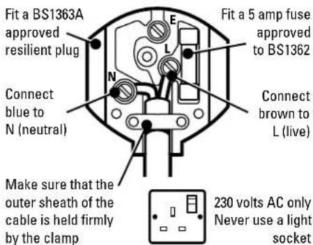
Make sure that the outer sheath of the cable is held firmly by the clamp
Warning! Never connect live or neutral wires to the earth pin marked E or ⊥
AUSTRALIA AND NEW ZEALAND ONLY
Should the mains pug or cordset of this equipment be damaged it must only be replaced by an authorised Black & Decker service agent as special purpose tools are required.
EXTENSION CABLES
You can use up to 30m (100ft) of Black & Decker 2-core extension cable (or 3-core extension cable in Australia and New Zealand) without undue loss of power.
Note: An extension cable should not be used unless absolutely necessary. Use of an improper extension cable could result in a risk of fire and electric shock. If an extension cable must be used, make sure it is properly wired and in good electrical condition.
UNWANTED TOOLS AND THE ENVIRONMENT
Should you find one day that the tool needs replacement or is of no further use, think of the protection of the environment. Black & Decker service agents will accept old tools and will dispose of them in an environmentally safe way.
THE BLACK & DECKER GUARANTEE (UK, AUSTRALIA AND NEW ZEALAND ONLY)
If your Black & Decker product becomes defective due to faulty materials and workmanship, within 24 months from the date of purchase, we guarantee to either replace all defective parts or at our discretion, replace the unit free of charge provided that:
• The product is returned to us or our authorised repairers with evidence of date of purchase.
• The product has not been used for trade, professional or hire purposes.
ENGLISH
• The product has not been subjected to misuse or neglect.
• The product has not sustained any damage through foreign objects, substances or accidents.
• Repairs have not been attempted by anyone other than our authorised repair distributors.
This guarantee is offered as an extra benefit and is additional to your statutory rights.
AFTER SALES SERVICE FOR YOUR BLACK & DECKER PRODUCT (UK, AUSTRALIA AND NEW ZEALAND ONLY)
Black & Decker offers a nationwide network of authorised service agents. The use of other than genuine Black & Decker accessories and parts may damage or reduce the performance of your Black & Decker product and may also endanger the user. The terms and conditions of the warranty may also be effected.
OUR AFTER SALES SERVICE POLICY (UK, AUSTRALIA AND NEW ZEALAND ONLY)
It is our aim that all Black & Decker customers should be totally satisfied with their Black & Decker product and after sales service, but if help or advice is needed please contact a local Black & Decker authorised repair agent manager who will be happy to help. Full details of our unique after sales service can be obtained from any of our Black & Decker authorised repair agents.
ACCESSORIES
The performance of any power tool is dependent upon the accessory used. Black & Decker accessories are engineered to high quality standards and are designed to enhance the performance of the power tool. Buying a Black & Decker accessory will ensure that you get the very best from your Black & Decker power tool. Black & Decker accessories available include metal and stone cutting discs, grinding discs, wire brushes and sanding discs.
TECHNICAL DATA
The level of sound pressure of this tool is in accordance with EEC legislation. You must wear ear protection when using this tool.
CD500 KG68 KG75
Disc diameter 115mm 115mm 115mm
Power input 680W 680W 750W
natural_image
Line drawing of a hand holding a device with motion lines indicating movement (no text or symbols)To switch your angle grinder on, push the slider switch forward. To switch your angle grinder off, press the rear of the slider switch.
Spring action returns the switch to the off position.
FITTING THE WHEEL GUARD
natural_image
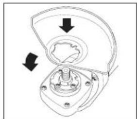
Mechanical component diagram showing a housing with arrows indicating direction of movement (no text or symbols)Place the angle grinder on a table, spindle up. Align the lug with the slot in the bracket. Press the guard down and turn it in the direction of the arrow.
Note: The guard locking pin prevents the guard from coming loose.
FITTING THE DISCS
Grinding and finishing
Use a rigid abrasive disc with a depressed centre for surface grinding and finishing. The maximum diameter
ENGLISH
disc you can use is 115mm. The maximum thickness is 6mm and the centre hole is 22mm.
Cutting metal
Use a cutting disc for cutting rod, pipe and metal section. The maximum diameter you can use is 115mm. The maximum thickness is 3.5mm and the centre hole is 22mm.
Cutting masonry
Use a flat cutting disc. The maximum diameter you can use is 115mm. Always approach the work at the angle at which you will cut. Maintain this angle throughout the cut and do not exert a side load on the disc.
Proceed as follows:
Disconnect the plug from the electricity supply.
natural_image
Mechanical assembly diagram showing a hand holding a bolt and nut assembly (no text or labels)Ensure the guard is fitted.
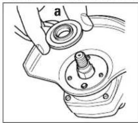
Place the inner flange (a) on the spindle. Ensure it is located on the two flats.
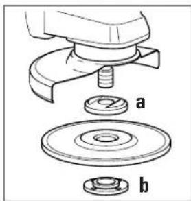
Place the abrasive disc on the spindle and inner flange (a). Ensure it is correctly located.
natural_image
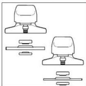
Technical line drawing of a mechanical component assembly (no text or symbols)Fit the threaded outer flange (b), making sure it is facing in the correct direction for the type of disc fitted. For grinding discs, the flange (b) is fitted with the raised portion facing
towards the disc. For cutting discs, the flange (b) is fitted with the inner portion facing away from the disc.
natural_image
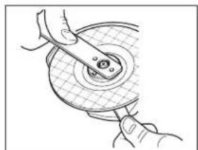
Illustration of hands using a tool to adjust or install a circular component (no text or symbols visible)Hold the spanner on the flats of the spindle to prevent rotation of the disc and tighten the outer flange with the spanner provided.
natural_image
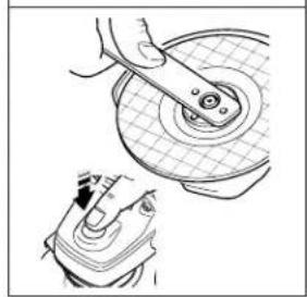
Technical illustration of a mechanical assembly with a tool interacting with a circular component (no text or symbols)KG75 only: Press in the spindle lock button and rotate the spindle until it locks. Keeping the lock button pressed in, tighten the outer flange with the spanner provided.
REMOVING THE GUARD (SANDING ONLY)
natural_image
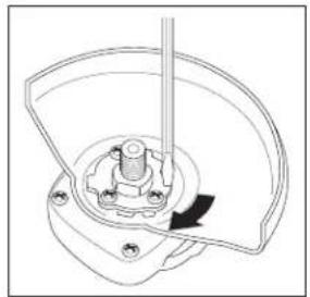
Technical line drawing of a mechanical component with a central hub and mounting holes (no text or symbols)Hold the tool in your hand. Rotate the guard in the direction of the arrow. Use a screwdriver to press the locking pin in the slot. Release the guard.
FITTING SANDING DISCS
Use a sanding disc with the backing pad for sanding with your angle grinder.
Disconnect the plug from the electricity supply.
natural_image
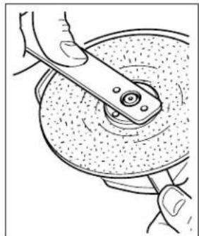
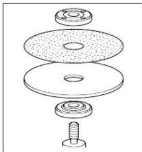
Illustration of hands using a tool to cut a circular component (no text or symbols visible)Remove the guard. Place the flange on the spindle. Place the backing pad on the spindle and inner flange, ensuring it is correctly located. Mount the fibre backed abrasive disc on the backing pad.
ENGLISH
natural_image
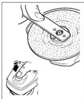
Illustration of a hand using a tool to lift a car brake disc, with a close-up view of the mechanical component (no text or symbols)Fit the threaded outer flange and tighten as explained in 'Fitting the discs'.
natural_image
Exploded view diagram of a mechanical assembly showing layered components (no text or labels)HANDY HINTS
natural_image
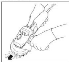
Line drawing of hands using a power tool to clean or adjust a circular component (no text or symbols present)Hold your angle grinder firmly with one hand around the side handle and the other around the body of your angle grinder.
- Always position the guard so that as much of the exposed disc as possible is pointing away from you.
- Be prepared for a stream of sparks when the disc touches the metal.
natural_image
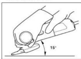
Illustration of a hand using a tool to lift a small object, with a 15° angle标注 (no text or symbols beyond the label)When grinding, always maintain the correct angle between the disc and the work surface (15°). This increases the removal capacity
of the disc and avoids unnecessary overloading.
OVERLOAD
Overloading will cause damage to the motor of your angle grinder. This can happen if your angle grinder is subjected to heavy duty use for prolonged periods of use. Do not in any circumstances, attempt to exert too much pressure on your angle grinder to speed up your work. The abrasive discs operate more efficiently when a light pressure is exerted, thus avoiding a drop in the speed of your angle grinder (see Tool care).
TOOL CARE
Keep guards, air vents and the motor housing as clear as possible of dust and dirt. Wipe with a clean cloth and blow through with a low-pressure air supply. Excessive build-up of metal dust can cause tracking of electrical current from the internal parts to exposed metal parts. Do not overload your angle grinder. Overloading causes a reduction in speed and efficiency, causing your angle grinder to become too hot. If this happens, operate your angle grinder under no load for one or two minutes until it has cooled to normal operating temperature. Switching your angle grinder off under load will reduce the life of the switch.
CLEANING
Use only mild soap and a slightly damp cloth to clean your angle grinder. Many household cleaners contain chemicals which could seriously damage the plastic. Also, do not use petrol, turpentine, lacquer or paint thinners or similar products. Never let any liquid get inside the tool and never immerse any part of the tool into liquid.
EC DECLARATION OF CONFORMITY
We declare that units: CD500, KG68, KG75 conform to 98/37/EEC, 89/336/EEC, EN55014, 73/23/EEC, EN50144, EN61000
A weighted sound pressure 89.9dB (A) A weighted sound power 102.9dB (A) Hand/arm weighted vibration <2.5m/s²

Brian Cooke - Director of Engineering Black & Decker Ltd, Spennymoor, County Durham DL16 6JG United Kingdom
The Black & Decker policy is one of continuous improvement to our product and as such we reserve the right to change the product specification without prior notice.






Australia DeWalt Industrial Power Tool Company Tel: 03 9895 9200
(Distributors of Black & Decker products) Fax: 03 9899 7465
7 Clarice Road, Box Hill, Victoria 3128
New Zealand Black & Decker Tel: 09 579 7600
483 Great South Road Fax: 09 579 8200
Penrose, Auckland
South Africa Black & Decker South Africa (Pty) Ltd Tel: 011 314 4431
Suite no 107, PostNet X65 Fax: 011 314 4435
Halfway House 1685
United Kingdom Black & Decker Tel: 01753 574277
210 Bath Road, Slough Tlx: 848317 BAND MH
Berkshire SL1 3YD Fax: 01753 551155
Date of your purchase:
Address of the dealer where your angle grinder was purchased:
Name:
House number or name and street:
Town:
County or state:
Postcode:
Country:
Product catalogue number:
Data protection act: Tick this box if you prefer not to receive
information from Black & Decker or other companies.

Please complete this section immediately after the purchase of your angle grinder and post it to the Black & Decker address in your country (above).
If you live in Australia or New Zealand, please register your purchase by phone.
- Contents
- Small angle grinder user manual
- SAFETY INSTRUCTIONS
- For safe operation:
- ADDITIONAL SAFETY INSTRUCTIONS FOR SMALL ANGLE GRINDERS
- ENGLISH
- Save these instructions!
- DOUBLE INSULATION
- ELECTRICAL SAFETY
- MAINS PLUG REPLACEMENT (UK ONLY)
- AUSTRALIA AND NEW ZEALAND ONLY
- EXTENSION CABLES
- UNWANTED TOOLS AND THE ENVIRONMENT
- THE BLACK & DECKER GUARANTEE (UK, AUSTRALIA AND NEW ZEALAND ONLY)
- AFTER SALES SERVICE FOR YOUR BLACK & DECKER PRODUCT (UK, AUSTRALIA AND NEW ZEALAND ONLY)
- OUR AFTER SALES SERVICE POLICY (UK, AUSTRALIA AND NEW ZEALAND ONLY)
- ACCESSORIES
- TECHNICAL DATA
- CD500 KG68 KG75
- FITTING THE DISCS
- Grinding and finishing
- Cutting metal
- Cutting masonry
- FITTING SANDING DISCS
- OVERLOAD
- TOOL CARE
- CLEANING
- EC DECLARATION OF CONFORMITY
Brand : BLACK & DECKER
Model : CD500
Category : Mill