
MCSCTG12S - Cooker Magic Chef - Free user manual and instructions
Find the device manual for free MCSCTG12S Magic Chef in PDF.


| Product Type | Gas Cooktop |
| Model Number | MCSCTG12S |
| Brand | Magic Chef |
| Dimensions (H x W x D) | 3.6" x 11.8" x 20.0" (91 x 300 x 510 mm) |
| Number of Burners | 2 |
| Rear Burner (Triple Ring) | 16,000 BTU |
| Front Burner (Auxiliary) | 5,000 BTU |
| Total BTU Output | 21,000 BTU |
| Fuel Type | Natural Gas (convertible to LP/Propane) |
| Ignition | Electronic spark ignition |
| Electrical Requirement | 120V AC, 60 Hz, grounded outlet |
| Gas Connection | 1/2" or 3/4" flexible line with manual shut-off valve |
| Gas Pressure Regulator | Included, adjustable for NG/LP |
| Safety Features | Flame failure safety valve (thermocouple), automatic shut-off |
| Minimum Clearance Above Cooktop | 30" (762 mm) to cabinets |
| Surface Material | Stainless steel |
| Grates Material | Cast iron |
| Cleaning Recommendation | Use stainless steel cleaner; avoid abrasive pads |
| Warranty | 1 year parts and labor (carry-in service) |
| Installation | Must be performed by qualified technician |
| Included Accessories | LP conversion kit, foam gasket, mounting clips |
| Certifications | ANSI Z21.1, CSA (compliant) |
| Product Registration | Recommended online at www.mcappliance.com/register |
Frequently Asked Questions - MCSCTG12S Magic Chef
User questions about MCSCTG12S Magic Chef
0 question about this device. Answer the ones you know or ask your own.
Ask a new question about this device
Download the instructions for your Cooker in PDF format for free! Find your manual MCSCTG12S - Magic Chef and take your electronic device back in hand. On this page are published all the documents necessary for the use of your device. MCSCTG12S by Magic Chef.
USER MANUAL MCSCTG12S Magic Chef
12-Inch Gas Cooktop
User's Manual
natural_image
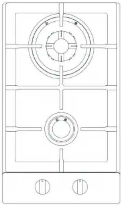
Technical line drawing of a gas stove or gas stove with circular vent and two side gauges (no text or symbols)Model MC PLEASE READ THIS MANUAL CAREFULLY BEFORE USING YOUR GAS COOKTOP AND KEEP IT FOR FUTURE REFERENCE.

PRODUCT REGISTRATION
Thank you for purchasing this Magic Chef® product. The first step to protect your new product is to complete the product registration on our website: www.mcappliance.com/register. The benefits of registering your product include the following:
-
Registering your product will allow us to contact you regarding a safety notification or product update.
-
Registering your product will allow for more efficient warranty service processing when warranty service is required.
-
Registering your product could act as your proof of purchase in the event of insurance loss.
Once again, thank you for purchasing this Magic Chef product.
CONTENTS
PRODUCT REGISTRATION 2
PRECAUTIONS 4
IMPORTANT SAFETY INSTRUCTIONS 5
SPECIFICATIONS....6
INSTALLATION REQUIREMENTS....7
INSTALLATION INSTRUCTIONS 9
OPERATION INSTRUCTIONS.... 16
CARE AND MAINTENANCE....19
LIMITED WARRANTY 20
PRECAUTIONS
EXPLANATION OF SYMBOLS
WARNING
Hazards or unsafe practices which COULD result in severe personal injury or death.
CAUTION
Hazards or unsafe practices which COULD result in minor personal injury.
THIS PRODUCT IS INTENDED FOR HOUSEHOLD USE ONLY
⚠ WARNING: Read and understand all safety precautions. Failure to follow all instructions described in this user manual may result in electric shock, fire and/or serious personal injury. The warnings, cautions and instructions discussed in this user manual cannot cover all possible conditions and situations that may occur.
⚠ WARNING: If information in this manual is not followed exactly, a fire or explosion may result causing property damage, personal injury or death.
- DO NOT store or use gasoline or other flammable vapors and liquids in the vicinity of this or any other appliance.
⚠ WARNING: What to Do If You Smell Gas
• DO NOT try to turn on any appliance.
• DO NOT touch any electrical switch.
• DO NOT use any phones in home.
- Immediately call your gas supplier from a phone outside of the home. (Ex: Go to a neighbor's home to call your gas supplier or fire department.)
• If the gas supplier cannot be reached, call the fire department.
• Installation and service must be performed by a qualified installer or service agency.
⚠ WARNING: State of California Proposition 65 Warnings
• This product contains one or more chemicals known to the State of California to cause cancer.
- This product contains one or more chemicals known to the State of California to cause birth defects or other reproductive harm.
IMPORTANT SAFETY INSTRUCTIONS
⚠ WARNING: To reduce the risk of fire, electrical shock, injury to persons, or damage when using the oven, follow basic precautions.
• Be sure the cooktop is properly installed by a qualified technician.
• DO NOT allow anyone to climb, stand or hang on cooktop.
- NEVER use this appliance to warm or heat a room. Doing so may result in carbon monoxide poisoning and overheating of the cooktop.
- DO NOT leave children alone or unattended. Children SHOULD NOT be left alone or unattended in the area where the cooktop is in use; they could be seriously burned or injured. Children SHOULD NEVER be allowed to sit or stand on any part of the cooktop; they could be seriously burned or injured.
• Wear proper apparel. Loose fitting or hanging garments SHOULD NOT be worn while utilizing the cooktop.
- DO NOT repair or replace any part of the oven unless specifically recommended in the manual. All other servicing should be referred to a qualified technician.
• DO NOT store flammable materials near the cooktop.
- DO NOT store or use combustible materials, gasoline or other flammable vapors and liquids near the vicinity of the cooktop or any other appliance.
- DO NOT use water on grease fires. NEVER pick up a flaming pan or pot. Turn the controls off. Smother the flaming pan or pot by covering it completely with a fitting lid, cookie sheet or flat tray. Use multi-purpose dry chemicals or foam-type fire extinguisher.
- Flaming grease outside of the pan or pot can be put out by covering it with baking soda, multi-purpose dry chemicals or foam-type fire extinguisher.
• Use only dry pot holders. Moist or damp potholders on hot surfaces may result in steamed burns.
- DO NOT heat un-opened food containers on the surface burners. Pressure could build up and the container can burst, causing injury.
• NEVER leave jars of fat drippings on or near your cooktop.
• DO NOT let cooking grease deposits accumulate in or near the cooktop, as this may cause a grease fire.
- In the event that a burner goes out and gas escapes, open a window or door. Wait at least 5 minutes before using cooktop.
• DO NOT use aluminum foil to line any part of the cooktop.
- If the cooktop is near a windows, be certain that the curtains or window covering are away from the cooktop burners.
• ALWAYS have a working smoke detector near the kitchen.
• DO NOT allow pans to dry boil.
- When the cooktop is in use DO NOT touch the burner grates, burner or surrounding areas as they may be hot and cause serious burns.
SPECIFICATIONS
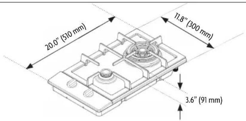
Figure 1
| Height | 3.6” (91 mm) | |
| Width | 11.8” (300 mm) | |
| Depth 20.0” (510 mm) | ||
| BTU | Rear Burner - Triple Ring 16000 BTU | |
| Front Burner - Auxiliary Burner 5000 BTU | ||
INSTALLATION REQUIREMENTS
▲ IMPORTANT: This appliance shall be installed only by qualified technician and in accordance with the manufacturer's installation instructions, local gas fitting regulations, municipal building codes, electrical wiring regulations, local water supply regulations.
▲ IMPORTANT: Save these instructions for local electrical inspectors use. Read and save these instructions for future use.
TOOLS AND PARTS
Tools Required
Figure 2
natural_image
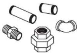
Illustration of various mechanical components including threaded bolts, hexagonal nut, and flanged nuts (no text or symbols)Pipe Fittings
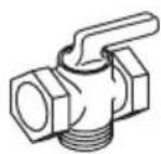
Shut-Off Valve

natural_image
Technical line drawing of a coiled mechanical component with threaded ends and flanges (no text or symbols)CSA-Approved Flexible 1/2" or 3/4" Gas Line
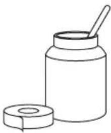
natural_image
Simple line drawing of a jar with a lid and a spoon (no text or symbols)Joint Sealant
Parts Required
Figure 3
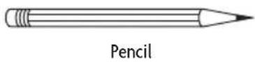
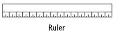
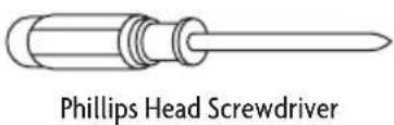
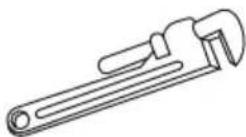
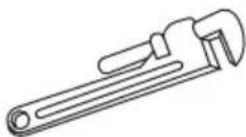
Pipe Wrench
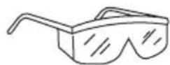
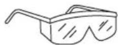
Safety Glasses
natural_image
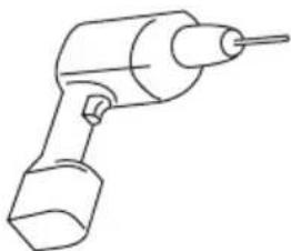
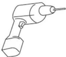
Line drawing of a handheld electric drill (no text or symbols)1/8" Drill Bit & Electric or Hand Drill
natural_image
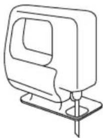
Line drawing of a mechanical component with a base and mounting bracket (no text or symbols)Saber Saw
LOCATION REQUIREMENTS
The air necessary for the combustion of the gas must be able to flow into the room naturally. The air must flow into the room directly through openings in the outside walls. These openings must have an unobstructed cross-section not less than 2m^3/h for each kw of power.
- The opening must be constructed so that it will not be obstructed from inside or outside, or constructed close to the floor. The opening is recommended to be on the side opposite to that on which the flue gases are discharged.
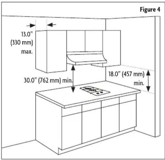
- Avoid placing cabinetry directly above cooktop when possible. If cabinetry is used above cooking surface, use cabinet no more than 13" deep.
- Working areas adjacent to the cooktop should have a 18" minimum clearance between countertop and cabinet bottom. Make sure the wall coverings, countertop and cabinets around the cooktop can withstand heat (up to 200°F) generated by the cooktop.
- Maintain 30" minimum clearance between cooktop surface and cabinets installed above the cooktop.
- If a range hood is installed above the cooktop, it is important that the 30" minimum clearance between the cooktop and bottom of the range hood is maintained. The range hood must be connected directly to flues or to the outside.
- A range hood with minimum 350 CFM that projects at least 5" beyond front of cabinets can reduce risk of burns caused by reaching over heated surface units.
GAS AND ELECTRICAL SUPPLY REQUIREMENTS
Installation must comply with local codes. In the absence of local codes, the gas cooktop must comply with the National Fuel Gas Code ANSI Z223.1- latest edition in the United States, or in Canada CAN/CGA B149.1 and CAN/CGA B149.2 and the National Electrical Code ANSI/NFPA No.70 – latest edition in United States, or in Canada CSA Standard C22.1, Canadian Electrical Code, Part 1, and local code requirements.
Gas Supply Requirements
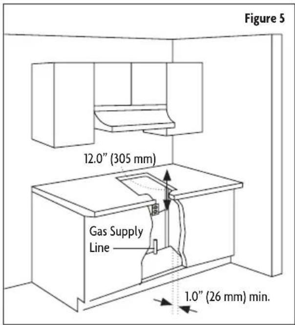
The gas supply should be located near the opening for this cooktop and a minimum of 1" from the back wall. This cooktop is manufactured for natural gas and is designed to operate at 5" water column pressure. The regulator is required to provide a minimum of 6" water column to a maximum of 14" water column to the cooktop regulator.
Electrical Supply Requirements
The electric spark ignition feature for this model requires a 120V electrical power supply and should be located 12" below the countertop and within reach of the cooktops four-foot power cord.
INSTALLATION INSTRUCTIONS
⚠ WARNING: Installation and service must be performed by a qualified installer, service agency or the gas supplier. Failure to do so can result in death, fire, or electrical shock.
▲ IMPORTANT: Save these instructions for local electrical inspectors use. Read and save these instructions for future use.
⚠ WARNING: Installations for Gas and Electric
- The cooktop is manufactured for use with Natural Gas. The cooktop can be converted for use with propane gas using the propane conversion kit supplied with the cooktop.
- Be sure the cooktop being installed is correct for the type of gas being used.
• Refer to the rating plate located on the underside of the burner box. - When connecting the unit for propane gas, make certain the propane tank is equipped with its own high pressure regulator.
- In addition, the pressure regulator supplied with the cooktop must be installed on the gas inlet pipe going to the cooktop.
INSTALLING COOKTOP
-
Use as 24" or deeper base cabinet.
-
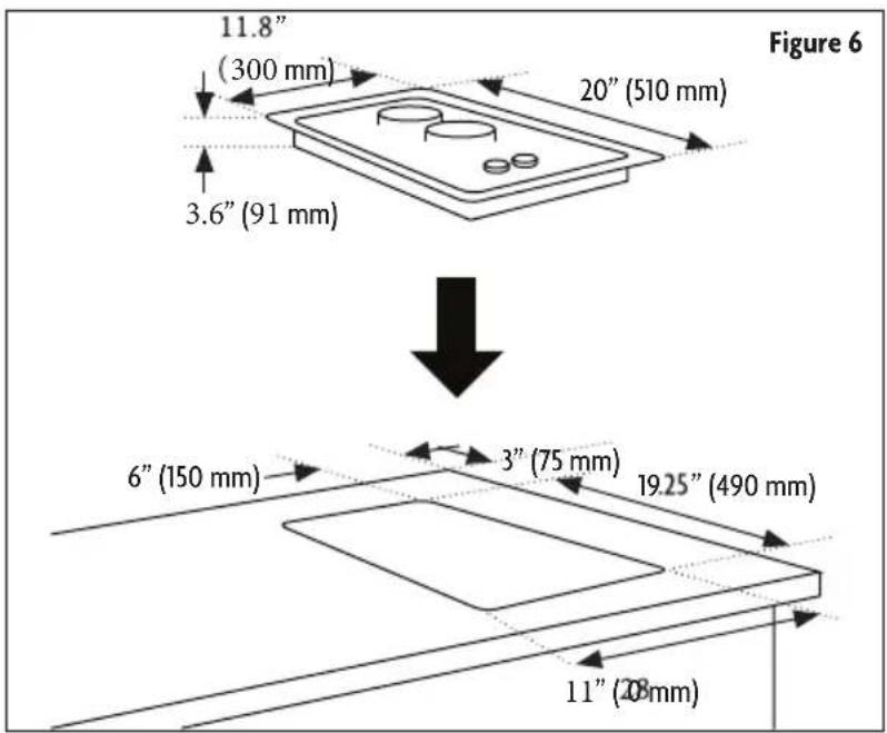
Cut the opening in the countertop. To ensure accuracy it is best to make a template for the opening. Make sure the sides are parallel also rear and front cuts are exactly perpendicular to the sides. Keep in mind all minimum clearances. (Refer to Figure 6.)
-
Before installing the cooktop into the opening in the countertop, remove all grates and burner caps.
-
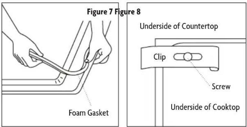
Turn the cooktop upside down and place the special foam gasket around the bottom edge of the cooktop. It is important that the gasket is fixed evenly without any gaps or overlapping, this is to prevent liquid seeping underneath the cooktop. (Refer to Figure 7.)
-
After the foam gasket is installed, place the cooktop into the countertop. (Refer to Figure 6.)
-
Secure the cooktop from underneath with the supplied clips and screws. (Refer to Figure 8.)
GAS CONNECTION
WARNING: Explosion Hazard
• Use a new CSA International approved gas supply line.
• Install a shut-off valve.
• Securely tighten all gas connections.
- Failure to do so can result in death, explosion, or fire.
- If connected to LP, have a qualified person make sure gas pressure does not exceed 14" (36cm) water column.
• Examples of a qualified person include: licensed heating personnel, authorized gas company personnel, and authorized service personnel.
▲ WARNING: NEVER reuse an old flexible connector. The utilization of an old flexible connector may cause gas leakage and personal injury.
▲ NOTE: ALWAYS use a new flexible connector when installing a gas appliance.
NOTE: ALWAYS apply thread compound approved for use with LP or Natural Gas to all thread connections.
Gas Pressure Regulator
The gas pressure regulator supplied with this cooktop must be used. For proper operation the inlet pressure to the regulator should be as follows. (Refer to Figure 9.)
Natural Gas
• Minimum Inlet Pressure: 5" WCP (Water Column Pressure)
• Maximum Supply Pressure: 6" WCP (Water Column Pressure)
LP Gas
• Minimum Inlet Pressure: 11" WCP (Water Column Pressure)
• Maximum Supply Pressure: 12" WCP (Water Column Pressure)
NOTE: Contact your local gas supplier if you are not sure about the inlet pressure.
The pressure regulator must be connected in series with the manifold of the cooktop and must remain in series with the supply line regardless the type of gas being used.
Gas Shut-Off Valve
The gas supply line must be equipped with a manual shut-off valve. This valve should be located in the same room but external to the cooktop. It should be in a location that allows ease of opening and closing. DO NOT block access to shut-off valve. The valve is for turning on or shutting off gas to the cooktop. (Refer to Figure 10.)
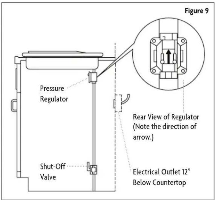
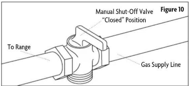
▲ IMPORTANT: It is important to know how and where to shut off the gas supply to the cooktop.
- The gas inlet is located on the bottom of the cooktop at the rear and 8½ from the right hand edge of the cooktop. Make gas connection through rear wall, or on cabinet floor at rear. Install the house gas supply at least 1" from the back wall.
- When installing, fit a safety tap at the end of the pipeline. The cooktop is manufactured and tested for natural gas.
▲ IMPORTANT: Make sure the type of gas being supplied to the cooktop is the same as that show on the label affixed to the underside of the cooktop.
▲ NOTE: All connections must be wrench-tightened. Use only pipe-joint compound made for use with Natural and LP gas.
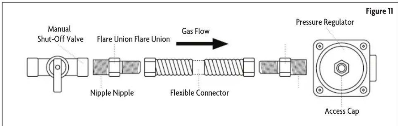
flowchart
graph LR
    A["Manual Shut-Off Valve"] --> B["Flare Union Flare Union"]
    B --> C["Gas Flow"]
    C --> D["Nipple Nipple"]
    D --> E["Flexible Connector"]
    E --> F["Pressure Regulator"]
    F --> G["Access Cap"]
- Install the pressure regulator with the arrow pointing up toward the bottom of the cooktop base and in position where you can reach the regulator cap.
• DO NOT make connections to the gas regulator too tight. Making the connections too tight may crack the regulator and cause gas leak.
• DO NOT allow the regulator to turn on the pipe when tightening.
- Apply Natural Gas/LP Gas pipe joint compound to the smaller thread ends of the flexible connector adapters
- Attach 1 adapter and nipple to the gas pressure regulator and the other adapter and nipple to the gas shut-off valve. Tighten both adapters and nipples.
- Using a wrench and pliers attach the flexible connector to both adapters. Check to ensure the connector is not kinked or damaged.
Completing Gas Connection
- Check to make sure all burner knobs are in the OFF position.
- Open the manual shut-off valve in the gas supply line.
• The valve is open when the handle is parallel to the gas pipe.
- Test all connections by brushing on an approved non-corrosive leak-detection solution.
• Bubbles indicates a leak, correct any leaks found.
- Check the alignment of the control knob valves after connecting the cooktop to the gas supply to be sure the cooktop manifold pipe has not moved.
CAUTION: Misalignment could cause the valve stems to rub on the control panel, resulting in a gas leak at the valve.
▲ NOTE: Disconnect this cooktop and its individual manual shut-off valve from the gas supply piping system during any pressure testing of that system at test pressures greater than 1/2 psig (3.5kPa or 14" water column).
▲ NOTE: Isolate the cooktop from the gas supply piping system by closing its individual manual shut-off valve during any pressure testing of the gas supply piping system at test pressure equal to or less than 1/2 psig (3.5 kPa or 14" water column).
GAS CONVERSION
WARNING: Explosion Hazard
• Use a new CSA International approved gas supply line.
• Install a shut-off valve.
• Securely tighten all gas connections.
- Failure to do so can result in death, explosion, or fire.
- If connected to LP, have a qualified person make sure gas pressure does not exceed 14" (36cm) water column.
• Examples of a qualified person include: licensed heating personnel, authorized gas company personnel, and authorized service personnel.
The range can be used with Natural Gas or LP/Propane Gas. The range is manufactured from the factory for use with Natural Gas. A kit for converting to LP/Propane Gas is supplied with your cooktop. The kit is marked “For LP/Propane Gas Conversion”.
▲ NOTE: When the cooktop is converted for LP/Propane Gas, the LP gas supply is required to provide a minimum of 10" to a maximum of 14" water column to the cooktop regulator.
The conversion must be performed by a qualified service technician in accordance with the kit instructions and all local codes/requirements.
CAUTION: Failure to follow instructions could result in serious injury.
Parts Required
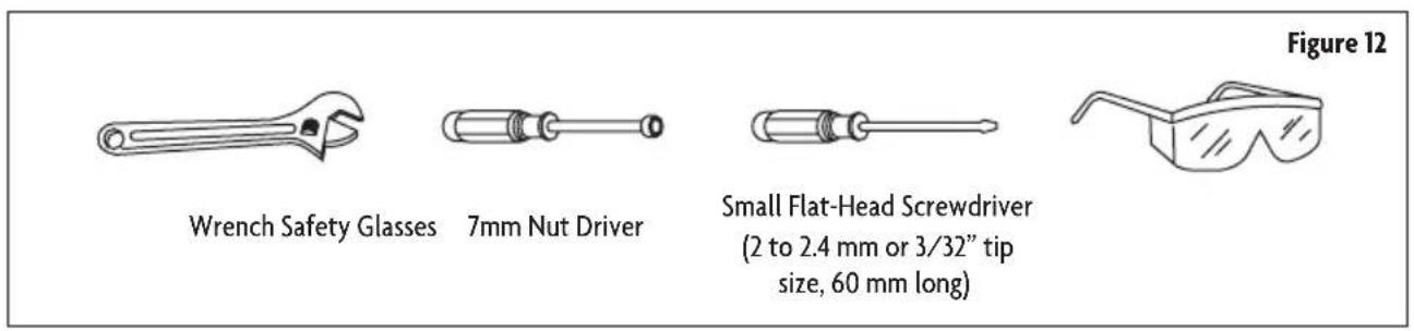
Converting to LP/Propane Gas
| Burner Type | Max Output Min Output Natural Gas LPG | |||||
| Kw Kw | Nozzle (mm) | Cons ( M^2/h ) | Nozzle (mm) | Cons (g/h) | ||
| Auxiliary Burner 1 | 0.31 x 1.10 | 0.11 x 0 | 70 73 | |||
| Triple Ring Burner | 4.5 | 1.5 | 5 x ø0.99 | 0.43 | 5 x ø0.56 | 327 |
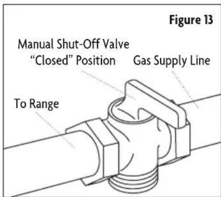
- Turn the manual shut-off valve to the closed position. (Refer to Figure 13.)
- Unplug range or disconnect power.
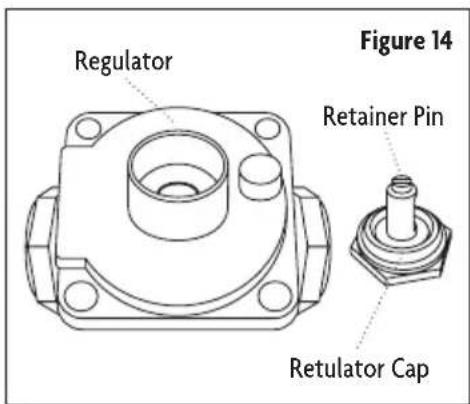
- Unscrew the regulator cap with the wrench. (Refer to Figure 14.)
flowchart
graph LR
    A["Retainer Pin Regulator"] --> B["Retulator Cap"]
    B --> C["Step 1"]
    C --> D["Step 2"]
    D --> E["Step 3"]
    E --> F["Step 4"]
    F --> G["Step 5"]
    G --> H["Figure 15"]
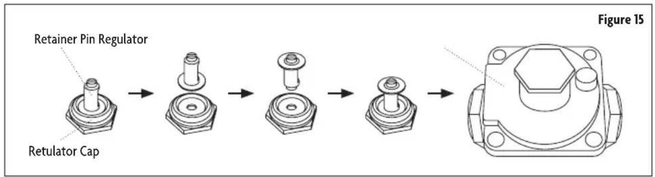
- Remove the retainer pin that is currently positioned for use with Natural Gas. (Refer to Figure 15.)
- Turn the retainer pin upside down and re-install into regulator cap. (Refer to Figure 15.)
- Screw the regulator cap back into the regulator and reattach the regulator to the nipple and flare union. (Refer to Figure 15.)
Converting Surface Hob Burners (Natural Gas to LP Gas)
- Remove the burner grates, burner caps and burner heads.
- Using a 7 mm nut driver, remove the burner orifices.
Figure 16
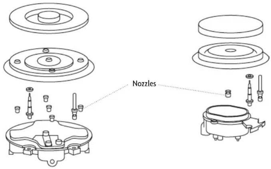
Triple Ring Burner - 5 Nozzles
Auxiliary Burner - 1 Nozzle
-
Install the proper orifices in replace of the ones that were removed.
-
Re-install the burner bases, heads and top grates. Make sure the burner caps are properly seated on the burner heads.
▲ NOTE: The triple burner has only two injectors, one injector mounted in the center and one mounted below the cover plate. To access the second injector, remove the two screws and the cover plate.
▲ IMPORTANT: Once the conversion has been completed and has passed testing, fill out the conversion sticker and include your name, organization and the date conversion is made. Apply the sticker near the cooktop gas inlet opening to alert others in the future that this appliance has been converted. If converting back to Natural Gas, remove the sticker so others know that the appliance is set to use its original gas.
ELECTRICAL CONNECTION
⚠ WARNING: Electrical Shock Hazard
• ALWAYS disconnect the electrical plug from the wall receptacle before servicing this unit
• Plug into a grounded 3 prong outlet.
- DO NOT remove the ground prong from the power cord plug.
• DO NOT use an adapter.
• DO NOT use an extension cord.
- Failure to do so can result in death, fire or electrical shock.
▲ NOTE: Before making the connection, make sure of the following.
- The safety circuit breaker and the electrical system are able to withstand the load of the appliance.
- The power supply system has a ground connection in good working order in accordance with the regulation.
- The electrical socket should be easily accessible with the appliance installed. In all cases, the power supply lead must be positioned so that it does not reach a temperature of 122°F above the room temperature at any point.
⚠ WARNING: Severe shock or damage to the cooktop may occur if the cooktop is not installed by a qualified service technician.
⚠ WARNING: If for any reason a gas control knob is turned ON and there is no electric power to operate the electronic igniter of the cooktop, turn off all gas control knobs and wait 5 minutes for gas to dissipate before lighting the burner manually.
⚠ WARNING: To light the burner manually, carefully hold a lighted match to the burner ports and push and turn the gas control knob to HI until it lights and then turn the knob to the desired setting.
Assembling the Burners
The electrode of the electronic ignition system is positioned above the surface of the burner base. DO NOT remove a burner cap or touch the electrode of a burner while another is turned on. Damage or electrical shock may occur.
-
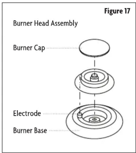
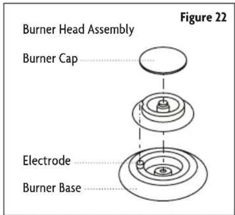
Place burner heads over the burner base. Make sure the hole in the burner head is properly aligned with the electrode in the burner base. (Refer to Figure 17.)
-
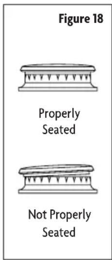
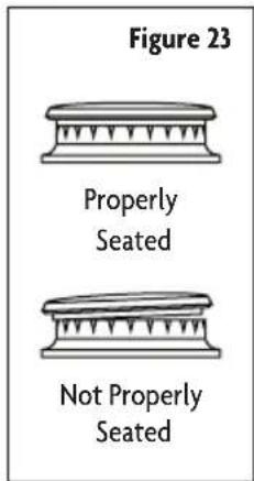
Place the burner caps on the burner heads. Make sure the burner caps are properly seated on the burner head. (Refer to Figure 18.)
-
Operation of the electric ignitors should be tested after the cooktop and supply line have been carefully checked for leaks and the cooktop has been connected to the electrical power.
• To check igniters, push and turn a burner valve to the light positon. All sparks will make a series of sparks, but only the burner turned to LITE with light.
How to Adjust Standard Burner
▲ IMPORTANT: Adjustments must be made with two other burners in operation on a medium setting. This prevents the upper row of the flames from being set too low, resulting in the flame being extinguished when other burners are turned on.
- Turn all burners on the highest setting and check the flames. The flames should all be blue in color (LP gas will have blue flames with yellow tips). Foreign particles in the gas line may cause an orange flame at first, but should disappear in a short period of time.
- Light one burner and turn to the lowest setting.
- Remove the control knob to the desired burner that you wish to adjust.
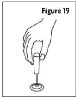
- Insert screwdriver through the access hole in the valve shaft. (Refer to Figure 19.)
- Slowly turn the screw until the flame appearance is correct.
• If the flames are too small or fluttered, open the valve more than the original setting.
• If the flames are too large, close the valve more than the original setting.
natural_image
Line drawing of a hand holding a glass over a small object, labeled 'Figure 19' (no other text or symbols)Testing Flame Stability
- Test 1: Turn the control knob from "HI" to "LO" quickly. If the upper row of flames goes out at this setting, increase the flame size and test again.
- Test 2: With the burner on "LO", open and close the cabinet door under the cooktop. If the flame is extinguished by the air currents created by the door movement, increase the flame height and re-test
Flame Check
• After all the flame adjustments have been made, turn all burners to the off position.
• “LITE” each burner individually and observe the flame at the “HI” position.
- Rotate the burner knob to the lowest setting and be sure the flame size decreases as the knob is rotated counter-clockwise.
OPERATION INSTRUCTIONS
WARNING: Fire Hazard
• DO NOT operate a burner using empty cookware or without cookware on the grate.
• DO NOT touch the burner when the igniters are clicking (sparking).
• DO NOT let the burner flame extend beyond the edge of the pan.
• Turn off all controls when done cooking.
- Failure to do so can result in death or fire.
• ALWAYS use the LITE position when igniting the top burners and make sure the burners have ignited.
- NEVER leave the surface burners unattended at high flame settings. Boil overs can cause smoke and greasy spillovers that may catch on fire.
• ALWAYS turn cookware handles toward the side or back of the range without extending over adjacent burners.
• ALWAYS turn the burner controls off before removing the cookware.
⚠️ CAUTION: Excessive flames are hazardous. Adjust the burner flame size so it does not extend beyond the edge of the cookware.
CAUTION: When utilizing pot holders. Only use dry pot/pan holders as moist or damp pot holders to hot surfaces may result in burns from steam. DO NOT let pot holders come near open flames when lifting cookware.
CAUTION: When utilizing glass cookware. Make sure the glass cookware is suitable for top range cooking.
CAUTION: Keep all plastic items away from the cooktop as they may melt if left too close to the heat.
⚠️ CAUTION: When removing the cooking grates, ALWAYS be certain that the controls for all burners are set to off. Make sure all cooking grates are cool before attempting to remove them
COOKTOP
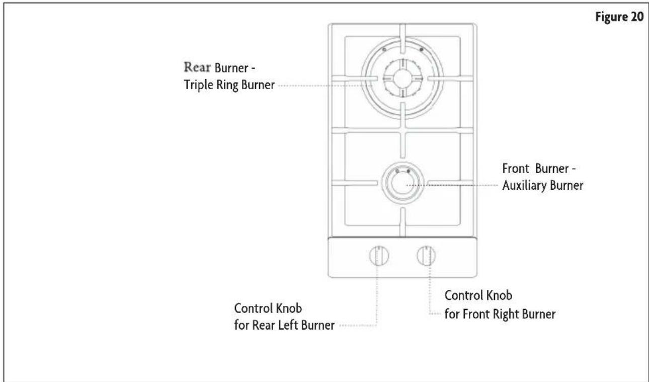
CONTROL KNOBS
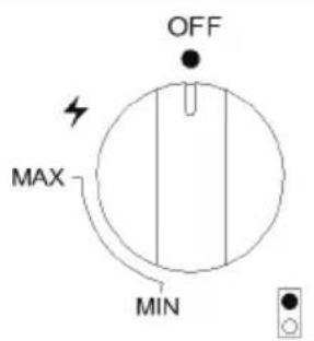
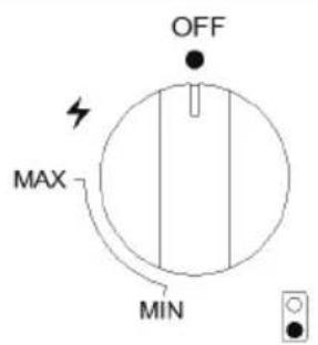
Figure 21
BURNERS
- Place a burner cap on each burner head, matching the cap size to the head size. (Refer to Figure 22.)
• The cap for each burner has an inner locating ring which centers the cap correctly on the burner head. - Be sure that all the burner caps and burner heads are correctly placed BEFORE using your appliance.
- The color of the flame will reflect the proper burner adjustment. A good flame should be clear, blue and steady. If the flame is yellow-orange in color then the burner needs to be adjusted or cleaned.
The gas burners utilize an electric ignition device located near each burner. By the means of spark igniters ensure the surface cooktop to light automatically.
- Push in and turn the control knob counterclockwise to the LITE position. All surface burners will click but only the burner with control knob turned to LITE will produce a flame.
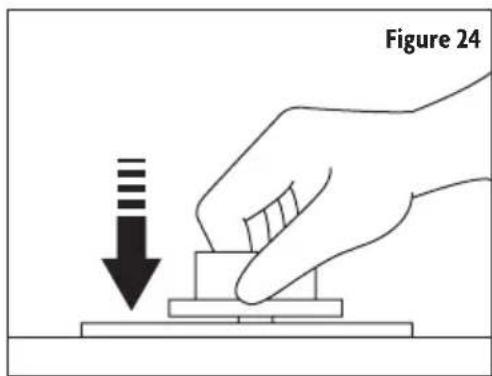
- After the burner ignites, keep the knob pressed down for 10 seconds. (Refer to Figure 24.) This allows the thermocouple to heat up and activate the safety valve.
- Check the flame to be even and then turn control knob to the desired flame size.
⚠️ CAUTION: ALWAYS use caution when lighting burners manually.
- In the instances of a power outage, carefully hold a lighted match to the burner ports and push and turn the gas control knob to HI until it lights and then turn the knob to the desired setting.
NOTE: ALWAYS position cooking cookware on the burner grate BEFORE lighting the burner.
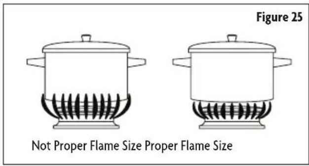
CAUTION: The flame SHOULD NOT extend beyond the sides or the pot or pan.
▲ NOTE: If any burner flame goes out due to draft or other reasons, the gas valve will shut off the gas supply. To re-ignite the burner, turn the gas valve to the ignition setting and push down the knob to ignite the burner.
COOKWARE
⚠️ CAUTION: NEVER extend the flame beyond the outer edge of the cookware. (Refer to Figure 25.)
DO NOT use cookware that is unstable or easily tippable as this can increase the chances of spill over and serious injury. To avoid spillover make sure cookware is large enough to contain the food properly.
DO NOT let the burner flames extend beyond the edge of the pan.
Use of cookware lids
Only use lids that are fitted for the cookware. This will allow shorten and more efficient cooking time.
Cooking with Canners and Pressure Cooker
The canner and pressure cooker must meet the required standards for cooktop cooking. Check to ensure the canner/pressure cooker has a flat bottom surface and is evenly balanced on the cooktop. Also check to ensure the lid fits properly to the canner/pressure cooker.
Proper Pan Size and Type
⚠ WARNING: Failure to follow these instructions can result to serious injury or death.
- UTILIZING PROPER PAN SIZE – Select cookware that is the appropriate in size to cover the burner grates.
- Use only certain types of glass, heatproof glass ceramic, ceramic, earthenware, or other glazed cookware that is suitable for the cooktop.
- DO NOT use cookware that is unstable or easily tippable as this can increase the chances of spill over and serious injury. To avoid spillover make sure cookware is large enough to contain the food properly.
• DO NOT let the burner flames extend beyond the edge of the pan.
• Turn off all controls when burners are not in use.
Cookware and the characteristics
Use the following chart as a guide for cookware material characteristics.
| Cookware Characteristics | |
| Aluminum | Heats quickly and evenly.Suitable for all types of cooking.Medium or heavy thickness is best for most cooking tasks. |
| Cast Iron | Heats slowly and evenly.Good for browning and frying.Maintains heat for slow cooking. |
| Stainless Steel | Heats quickly, but unevenly.A core or base of aluminum or copper on stainless steel provides even heating. |
DEEP FRYING
ALWAYS use a thermometer and adjust the surface control knob to the correct temperature. If the fat is too cool the food will absorb the fat. If the fat is too hot the food will brown quickly and the center will be undercooked DO NOT attempt to deep fry too much food at once as the food will neither brown nor cook properly.
⚠ CAUTION: During cooking process involving fats or oils, watch your food carefully because these substance may catch fire if brought to high temperatures.
CARE AND MAINTENANCE
▲ IMPORTANT: DO NOT attempt to clean or touch the cooktop while it is still hot. Some cleaners produce noxious fumes when applied to a hot surface. Failure to do so can result in serious bodily injury.
▲ CAUTION: To avoid possible burns or injuries, DO NOT attempt any of the following cleaning instructions before turning OFF all of the surface burners. ALWAYS allow all surface burners and grates to cool prior to cleaning.
▲ IMPORTANT: When cleaning the cooktop make sure all control are off and all surfaces are cool before cleaning any part of the cooktop
⚠️ CAUTION: Some cleaners can produce noxious flames if applied to a hot surface.
Stainless Steel
• DO NOT use soap-filled scouring pads, abrasive cleaners, cooktop cleaner, steel-wool pads, gritty wash cloths or abrasive paper towels.
• Recommended Cleaning Methods
• Recommended to use stainless steel cleaner or polish.
• Recommended to use vinegar for hard water spots.
- Recommended to use liquid detergent or all-purpose cleaner. Rinse well with clean water and dry with soft, lint-free cloth.
• Recommended to rub in the direction of grain to avoid damage.
Control Knobs
- For general cleaning use hot soupy water and a cloth. For built up of grease apply liquid detergent directly onto the built up area. Rinse with a damp cloth and dry.
• DO NOT use steel wool or acidic cleaners on the control knobs.
Grates and End Caps
• DO NOT clean until the grates and caps have cooled
• DO NOT reassemble grates and caps if they are still wet.
• To avoid chipping, DO NOT bang grates and caps against each other or hard surfaces.
• Recommended to utilize mildly abrasive cleaner.
• Recommended to utilize a non-abrasive cloth or plastic scrubbing pad.
Burner Spreader
- Recommended to frequently wash the burner spreader with boiling water and detergent to remove any deposit build up. This will maintain steady flame output.
• ALWAYS dry the burner spreader thoroughly before re-installing.

LIMITED WARRANTY
MC Appliance Corporation warrants each new Gas Cooktop to be free from defects in material and workmanship, and agrees to remedy any such defect or to furnish a new part(s), at the company's option, for any part(s) of the unit that has failed during the warranty period. Parts and labor expenses are covered on this unit for a period of one year from the date of purchase. A copy of the dated sales receipt/invoice is required to receive warranty service, replacement or refund.
This warranty covers appliances in use within the contiguous United States, Alaska, Hawaii and Puerto Rico. This warranty does not cover the following:
• Damages due to shipping damage or improper installation.
• Damages due to misuse or abuse.
• Content losses due to failure of the unit.
• Repairs performed by unauthorized service agents.
• Service calls that do not involve defects in material and workmanship such as instructions on proper use of the product or improper installation.
• Replacement or resetting of house fuses or circuit breakers.
• Failure of this product if used for other purposes than its intended purpose.
• Disposal costs for any failed unit not returned to our factory.
• Any delivery/installation costs incurred as the result of a unit that fails to perform as specified.
• Expenses for travel and transportation for product service if your appliance is located in a remote area where service by an authorized service technician is not available.
- The removal and reinstallation of your appliance if it is installed in an inaccessible location or is not installed in accordance with published installation instructions.
• Refunds for non repairable products are limited to the price paid for the unit per the sales receipt.
- This warranty is non transferable. This warranty applies only to the original purchaser and does not extend to any subsequent owner(s).
Limitations of Remedies and Exclusions:
Product repair in accordance with the terms herein, is your sole and exclusive remedy under this limited warranty. Any and all implied warranties including merchantability and fitness for a particular purpose are hereby limited to one year or the shortest period allowed by law. MC Appliance Corporation is not liable for incidental or consequential damages and no representative or person is authorized to assume for us any other liability in connection with the sale of this product. Under no circumstances is the consumer permitted to return this unit to the factory without the prior written consent of MC Appliance Corporation.
Some states prohibit the exclusion or limitation of incidental or consequential damages, or limitations on implied warranties. This warranty gives you specific legal rights, and you may also have other rights which vary from state to state.
| Model | Parts | Labor | Type of Service | |
| MCSCTG12S | One Year | One Year | Carry In | |
For Service or Assistance please call 888-775-0202 or visit us on the web at www.mcappliance.com to request warranty service or order parts.

CNA International, Inc. d/b/a MC Appliance Corporation. All rights reserved. Magic Chef® logo is a registered trademark of CNA International, Inc.
www.mcappliance.com Printed in China

natural_image
Technical line drawing of a gas stove or gas stove with circular vent and two side buttons (no text or symbols)Modelo MCSCTGIS LEA ESTE MANUAL ANTES DE UTILIZAR SU PLACA DE COCINA A GAS Y GUÁRDELO PARA FUTURA REFERENCIA.

natural_image
Illustration of various mechanical components including threaded bolts, hexagonal nut, and cylindrical parts (no text or symbols)natural_image
Technical line drawing of a threaded pipe fitting with flanges (no text or symbols)natural_image
Simple line drawing of a jar with a lid and a spoon (no text or symbols)Sellador de juntas
Piezas requeridas
Figura 3

Llave para tubo
Lentes de seguridad
natural_image
Line drawing of a handheld electric drill (no text or symbols)natural_image
Line drawing of a mechanical device with a base and mounting bracket (no text or symbols)Sierra eléctrica
natural_image
Line drawing of a hand holding a glass with a circular base, labeled 'Figura 19' (no other text or symbols)
Figura 21
QUEMADORES
CNA International, Inc. d/b/a MC Appliance Corporation. All rights reserved. Magic Chef® logo is a registered trademark of CNA International, Inc.
www.mcappliance.com Printed in China
- 12-Inch Gas Cooktop
- PRODUCT REGISTRATION
- CONTENTS
- PRECAUTIONS
- EXPLANATION OF SYMBOLS
- WARNING
- CAUTION
- THIS PRODUCT IS INTENDED FOR HOUSEHOLD USE ONLY
- IMPORTANT SAFETY INSTRUCTIONS
- SPECIFICATIONS
- INSTALLATION REQUIREMENTS
- TOOLS AND PARTS
- LOCATION REQUIREMENTS
- GAS AND ELECTRICAL SUPPLY REQUIREMENTS
- Gas Supply Requirements
- Electrical Supply Requirements
- INSTALLATION INSTRUCTIONS
- INSTALLING COOKTOP
- GAS CONNECTION
- WARNING: Explosion Hazard
- Gas Pressure Regulator
- Natural Gas
- LP Gas
- Gas Shut-Off Valve
- Completing Gas Connection
- GAS CONVERSION
- Converting Surface Hob Burners (Natural Gas to LP Gas)
- ELECTRICAL CONNECTION
- ⚠ WARNING: Electrical Shock Hazard
- ▲ NOTE: Before making the connection, make sure of the following.
- ⚠ WARNING: Severe shock or damage to the cooktop may occur if the cooktop is not installed by a qualified service technician.
- ⚠ WARNING: If for any reason a gas control knob is turned ON and there is no electric power to operate the electronic igniter of the cooktop, turn off all gas control knobs and wait 5 minutes for gas to dissipate before lighting the burner manually.
- ⚠ WARNING: To light the burner manually, carefully hold a lighted match to the burner ports and push and turn the gas control knob to HI until it lights and then turn the knob to the desired setting.
- Assembling the Burners
- How to Adjust Standard Burner
- Testing Flame Stability
- Flame Check
- OPERATION INSTRUCTIONS
- WARNING: Fire Hazard
- COOKTOP
- CONTROL KNOBS
- BURNERS
- COOKWARE
- DEEP FRYING
- CARE AND MAINTENANCE
- Stainless Steel
- Grates and End Caps
- Burner Spreader
- LIMITED WARRANTY
- Limitations of Remedies and Exclusions:
- QUEMADORES
Brand : Magic Chef
Model : MCSCTG12S
Category : Cooker