ET-D75LE6 - Projector accessory PANASONIC - Free user manual and instructions
Find the device manual for free ET-D75LE6 PANASONIC in PDF.

| Product Type | Projection Lens Replacement Kit |
| Brand | Panasonic |
| Model | ET-D75LE6 |
| Category | Projector Accessory |
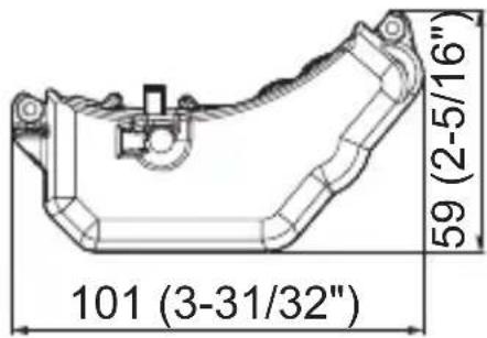
| Dimensions (W x H x D) | 101 mm × 82.5 mm × 59 mm (3-31/32" × 3-1/4" × 2-5/16") |
| Weight | Approx. 145 g (0.3 lb) |
| Motor Control System | Stepping control |
| Supported Lenses | ET-D75LE10, ET-D75LE20, ET-D75LE30, ET-D75LE40, ET-D75LE6, ET-D75LE8 |
| Supported Projectors | PT-RQ32K, PT-RZ31K, PT-RS30K, PT-RZ21K, PT-RS20K |
| Included Components | Stepping motor unit (×1), screws with captive washer M3×10 (×2) |
| Torque Specification | 0.6 to 0.8 N·m |
| Installation Requirements | Certified personnel, two persons, clean environment, soft flat surface |
| Safety Precautions | Keep screws away from children; use torque driver, not electric screwdriver or impact driver |
| Purpose | Speeds up zoom operation and improves zoom position reproducibility |
| Storage | Store unused motor units and screws in original packaging box in safe place |
Frequently Asked Questions - ET-D75LE6 PANASONIC
User questions about ET-D75LE6 PANASONIC
0 question about this device. Answer the ones you know or ask your own.
Ask a new question about this device
Download the instructions for your Projector accessory in PDF format for free! Find your manual ET-D75LE6 - PANASONIC and take your electronic device back in hand. On this page are published all the documents necessary for the use of your device. ET-D75LE6 by PANASONIC.
USER MANUAL ET-D75LE6 PANASONIC
Model No. ET-D75MKS10
natural_image
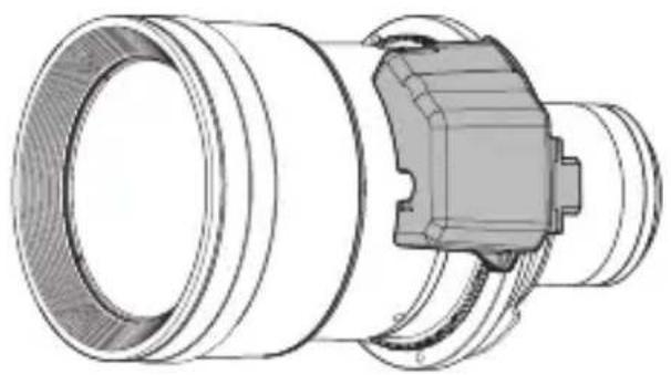
Technical line drawing of a mechanical component with concentric cylindrical and flanged sections (no text or symbols)* The figure above shows this product combined with the separately sold ET-D75LE10 Projection Lens.
* Unless specified otherwise, the ET-D75LE10 is used in the illustrations of projection lens in these instructions.
Thank you for purchasing this Panasonic product.
■ To customers
This “Operating Instructions” is intended for use by installation personnel. Be sure to employ certified personnel to perform the attaching and detaching work.
After the work is complete, have the installation personnel return this "Operating Instructions" to you, and save it for future use.
■ To installation personnel
Read this “Operating Instructions” carefully and then perform the work correctly and safely.
In particular, be sure to read "Read this first!" (page 3) before handling the product.
After the work is complete, return this "Operating Instructions" to the customer.

Contents
Read this first! 3
Before Use.... 4
Attaching / Detaching....5
Before attaching the stepping motor unit .... 5
Detaching the DC motor unit....6
Attaching the stepping motor unit....8
Detaching the stepping motor unit 9
Attaching the DC motor unit....9
Specifications 12
Dimensions 12
Environment care information for users in China

This symbol is only valid in China.
2-ENGLISH
Read this first!
Always follow these precautions
WARNING:
Do not allow children to reach the screws.
● The screws can cause personal injury if swallowed.
- If the screws are swallowed, seek medical advice immediately.
Before Use
This product is a projection lens replacement kit for speeding up the zoom operation to improve zoom position reproducibility.
■ Supported lens
ET-D75LE10 / ET-D75LE20 / ET-D75LE30 / ET-D75LE40 / ET-D75LE6 / ET-D75LE8
■ Supported projectors
PT-RQ32K / PT-RZ31K / PT-RS30K / PT-RZ21K / PT-RS20K
Note
- The alphabet letters at the end of projector model numbers are omitted in this document.
- Models other than the above may also be supported. Refer to the operating instructions of the projector you are using or check the Panasonic website (https://panasonic.net/cns/projector/).
■ Component List
| Part name Appearance (quantity) Application | ||
| Stepping motor unit | 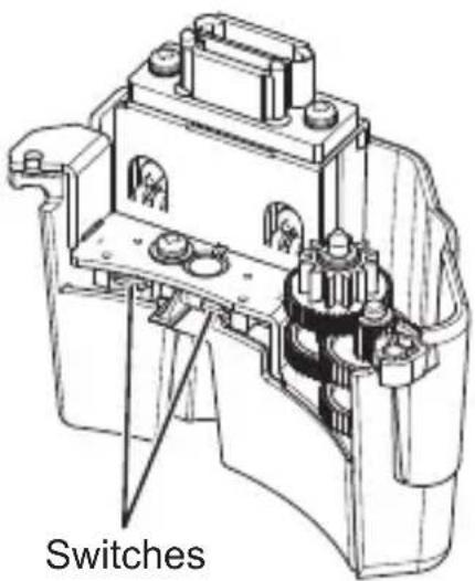 x1 x1 | This unit is used attached to a projection lens. |
| Screw | 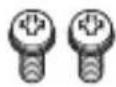 Screw with captive washer(M3x10) x2 Screw with captive washer(M3x10) x2 | These are used to attach the stepping motor unit to a projection lens. |
4-ENGLISH
Before Use (Continued)
- Store small parts appropriately in a location that is out of the reach of small children.
- When tightening the screws, use a torque driver. Do not use an electric screwdriver or impact driver.
Attention
- Place a stepping motor unit and DC motor unit that will not be used in this product's packaging box together with the screws, and store the packaging box in a safe place.
- When disposing of the packaging, dispose of it appropriately.
Attaching / Detaching
Before attaching the stepping motor unit
- Detach the projection lens from the projector before carrying out this work. (For details on attaching and detaching the projection lens, refer to the operating instructions of the projector.)
- Remove the DC motor unit from the projection lens before attaching the stepping motor unit.
Attention
● Perform the attaching and detaching work in a clean environment.
- Before carrying out the work, attach the supplied lens cover, etc. to the projection lens so that the lens surface does not get fingerprints or dirt on it or become scratched.
- Employ certified personnel to perform the attaching and detaching work.
- The attaching and detaching work must be carried out by two persons. One person should hold the lens while the other person performs the work to exchange the motor unit.
● Perform this work on soft material on a flat surface.
- When tightening the screws, use a torque driver. Do not use an electric screwdriver or impact driver.
Attaching / Detaching (Continued)
Do not touch the switches of this product and the removed DC motor unit because there is a risk of damaging them.
Detaching the DC motor unit
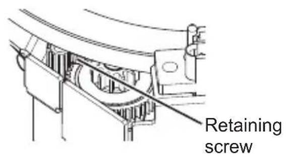
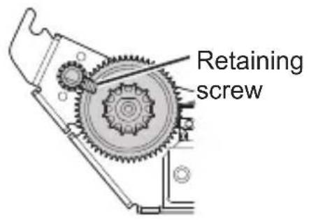
Attention
- Check that the retaining screw does not protrude over a gear. If it does protrude over a gear as shown in the figure, you will not be able to detach the DC motor unit. In that case, attach the lens to the projector and perform the zoom operation to move the position of the retaining screw.
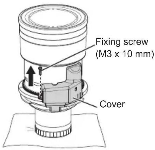
1) Remove the one fixing screw (M3 x 10 mm) from the cover.
Attention
- Screw locking agent is applied to the screw. Take care that it does not enter in between gears during removal.
6-ENGLISH
Attaching / Detaching (Continued)
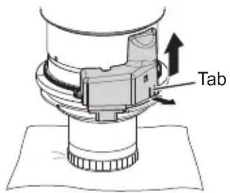
2) Pull the cover tab to raise up the cover and then remove the cover.
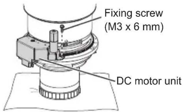
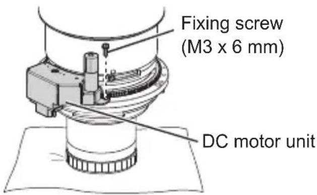
3) Remove the one fixing screw (M3 x 6 mm) from the DC motor unit.
natural_image
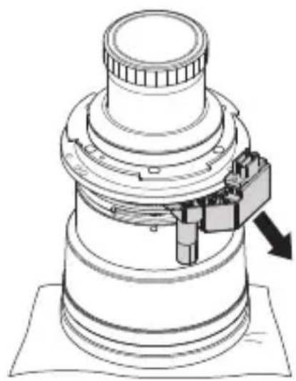
Technical line drawing of a mechanical assembly with no visible text or symbols4) Place the lens upside down.
- When the lens is turned upside down, one person should hold the DC motor unit so that it does not become detached and fall.
Note
- If the DC motor unit is detached without turning the lens upside down, a gear of the DC motor unit may fall off.
5) Remove the DC motor unit by pulling it down in a diagonal direction.
ENGLISH-7
Attaching / Detaching (Continued)
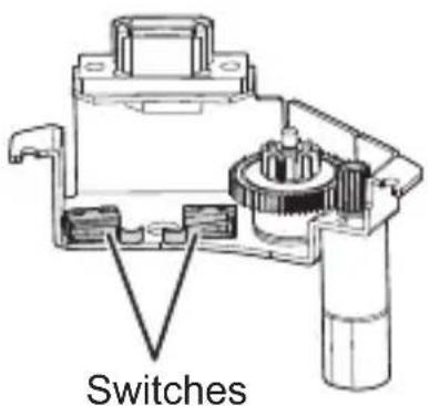
Attention
- Do not touch the switches because there is a risk of damaging them.
Attaching the stepping motor unit
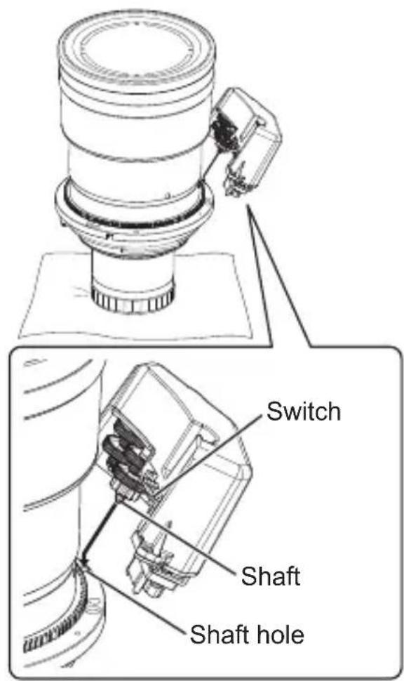
1) Turn the lens back over so that the top is facing up.
2) Insert the shaft of the stepping motor unit into the shaft hole of the lens.
Attention
- Do not touch the switches because there is a risk of damaging them.
8-ENGLISH
Attaching / Detaching (Continued)
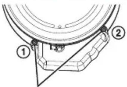
Supplied screws with captive washers (M3 x 10 mm)
3) Fix the stepping motor unit with the two supplied screws with captive washers (M3 x 10 mm) in the order ① and ② shown in the figure.
● Tighten the screws to a torque of 0.6 to 0.8 N·m.
Detaching the stepping motor unit
Detach the stepping motor unit by performing the procedure to attach the stepping motor unit in reverse.
* If the DC motor unit will be used again, attach it as described in "Attaching the DC motor unit" below.
Attaching the DC motor unit
natural_image
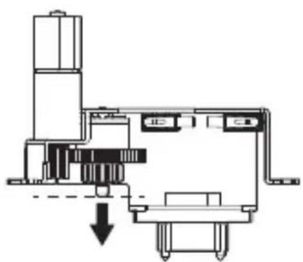
Pure mechanical assembly diagram without any text, numbers, or symbols1) Lower the gears of the DC motor unit to the end of the shaft.
- Hold the lowered gears so that they do not come off the shaft and fall.
Attaching / Detaching (Continued)
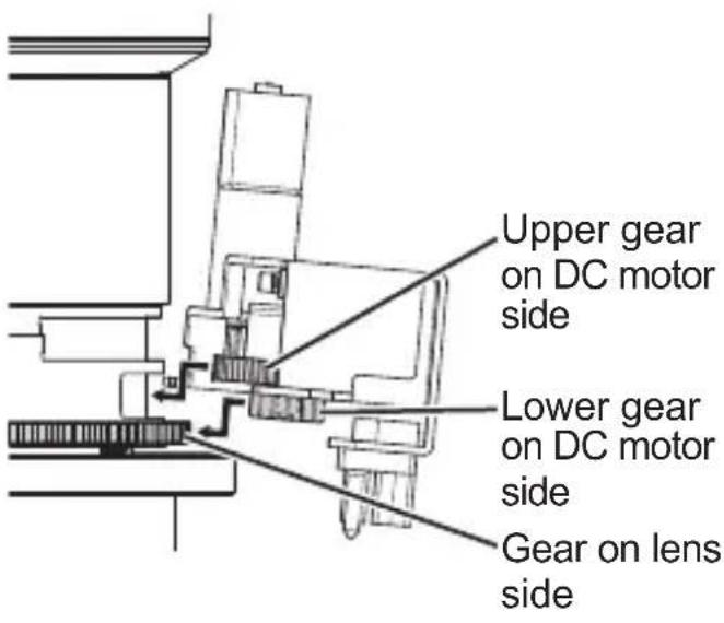
2) Hold the DC motor unit level and engage the lower gear with the gear on the lens side and insert the shaft into the shaft hole while inserting the large upper gear into the groove in the lens.
- If the gears have not been lowered to the end of the shaft, the gears will not engage because the shaft will contact the lens. If that happens, raise the DC motor unit until the shaft no longer contacts the lens and then engage the gears while pushing the DC motor unit in.
- If gear engagement is offset to the left or right, the shaft will not be able to be inserted in the shaft hole, so make adjustments using the left and right screw stop hole positions as a guide.
Attention
● Make sure that screw locking agent does not enter in between gears during attachment.
3) Fix the DC motor unit with the fixing screw (M3 x 6 mm).
- Use the screw that was removed in step 3) of "Detaching the DC motor unit" (page 7).
● Tighten the screw to a torque of 0.6 to 0.8 N·m.
Attention
- Remove the screw locking agent applied to the fixing screw before use.
10-ENGLISH
Attaching / Detaching (Continued)
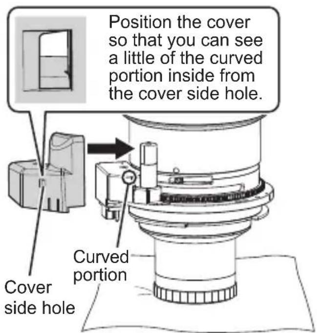
4) Bring the cover into contact with the lens from the side and then attach it by sliding downward until it locks into place with a click.
- Check that the cover tab is securely engaged.
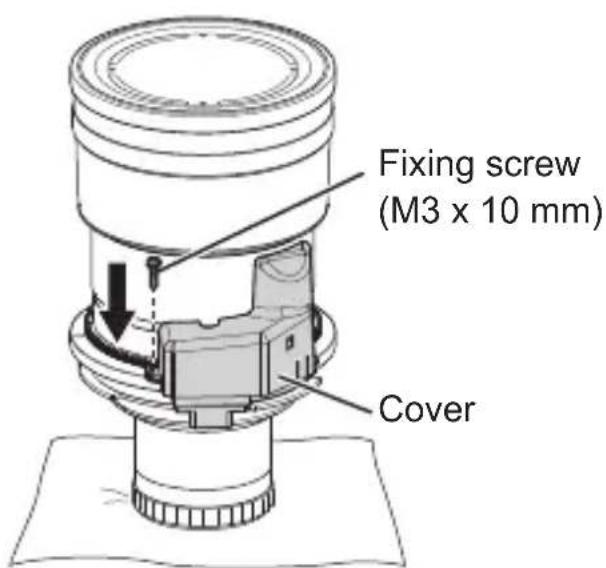
5) Fix the cover with the fixing screw (M3 x 10 mm).
- Use the screw that was removed in step 1) of "Detaching the DC motor unit" (page 6).
● Tighten the screw to a torque of 0.6 to 0.8 N·m.
Attention
- Remove the screw locking agent applied to the fixing screw before use.
Specifications
| Motor control system | Stepping control |
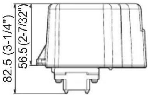
| Dimensions | Width 101 mm (3-31/32")Height 82.5 mm (3-1/4")Depth 59 mm (2-5/16") |
| Weight Approx. 145 | g (0.3 lb) |
Dimensions
(Unit: mm)
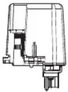
natural_image
Technical line drawing of a mechanical component or housing (no text or symbols visible)