
View DDX CAM - Cables for Computers and Peripherals Adder - Free user manual and instructions
Find the device manual for free View DDX CAM Adder in PDF.


| Product Type | KVM Extender Transmitter Module |
| Model Variants | DDX-CAM-DI (DisplayPort), DDX-CAM-DVI (DVI-D), DDX-CAM-VGA (VGA) |
| Video Interface | DVI-D (Single Link), DisplayPort, or VGA depending on variant |
| Maximum Video Resolution | Up to 1920 x 1200 @ 60Hz (WUXGA) via DVI-D; other interfaces support similar resolutions |
| USB Interface | USB 2.0 (Type B connector) for host computer connection; provides power to module |
| Link Cable Type | Shielded CAT6a or CAT7 (S/FTP, S/STP, or PiMF) with RJ-45 connectors |
| Maximum Link Distance to Switch | 10 meters (32 feet) |
| Maximum Link Distance to User Module | 50 meters (164 feet) when used without switch |
| Power Supply | Powered via USB from host computer (no external power adapter required) |
| Dimensions (approx.) | Compact module, fits in hand (exact dimensions not specified) |
| Weight (approx.) | Lightweight, typically under 200 g (not specified, estimate) |
| Operating Temperature | 0 to 40°C |
| Storage Temperature | -20 to 60°C |
| LED Indicators | Power and Link status LEDs on module |
| Mounting | Free-standing or can be secured with optional mounting bracket |
| Compliance | CE, FCC Class A, RoHS |
| Warranty | 2 years from date of purchase |
| Included Accessories | DDX-CAM module only (power adapter not required) |
| Optional Accessories | Shielded CAT7 cables, rack mount brackets for switch, additional modules |
| Supported Computer Platforms | Any computer with USB and DVI-D/DisplayPort/VGA output |
Frequently Asked Questions - View DDX CAM Adder
User questions about View DDX CAM Adder
0 question about this device. Answer the ones you know or ask your own.
Ask a new question about this device
Download the instructions for your Cables for Computers and Peripherals in PDF format for free! Find your manual View DDX CAM - Adder and take your electronic device back in hand. On this page are published all the documents necessary for the use of your device. View DDX CAM by Adder.
USER MANUAL View DDX CAM Adder
Experts in Connectivity Solutions

Switching Solutions
Contents
Introduction
Welcome....2
Cable type and distance rules....2
Access permissions....3
Port designations....4
Supplied items 5
Optional extras....7
Installation
Locations 8
Connections....9
Computer connections:Video....9
Computer connections: USB 9
Computer connections: Data link 9
Switch connections: Computer links 10
Switch connections: User console links....10
Switch connections: Network link....11
Switch connections: Options port....11
Switch connections: Power 12
Console connections:Video....13
Console connections: USB....13
Console connections:Audio 14
Console connections: Data link....14
Console connections: Options port....14
Console connections: Power 15
Configuration
Accessing DDX Matrix....16
Using DDX Matrix....17
The Dashboard page 17
Quick guide to creating a new installation....18
The Control page....19
The Configure pages 20
Configure > Consoles 24
Configure > Consoles > Receivers 27
Configure > Computers....28
Configure > Computers > Transmitters ....30
Reallocating ports....31
The Users page 32
The Maintenance pages....33
Maintenance > Diagnostics ....33
Maintenance > System Operations ....34
Maintenance > Settings 35
Resetting and recovering 36
Operation
Viewing the OSD....37
Using the Virtual Control Panel to adjust VGA inputs....38
USB Improvements 38
Using Audio 39
Indicators 40
Further information
Getting assistance 42
Appendix I - Link cable interference protection....43
Appendix 2 - Firmware upgrades for basic extender installations .....44
Appendix 3 - Open source licenses....44
Warranty and Safety information 49
Radio frequency energy 50
Index

Introduction
WELCOME
Thank you for choosing the AdderView DDX system. This adaptive system makes sharing numerous host computers among multiple users straightforward and flexible. Every computer is linked, via its USB and video ports, to a compact DDX-CAM module while each set of peripherals are connected to a DDX-USR module (to form Consoles).
The various computers and consoles are then linked, via CAT6a or CAT7 cable with S/FTP, S/STP or PiMF shielding (see Appendix 1 for details), to a central DDX switch. Each user can then, subject to the privileges granted by the admin, gain quick access to any of the required computers.

flowchart
graph TD
    A["COMPUTER"] --> B["DDX-CAM"]
    C["COMPUTER"] --> B
    D["COMPUTER"] --> E["DDX-CAM"]
    F["COMPUTER"] --> G["DDX-CAM"]
    H["COMPUTER"] --> I["DDX-CAM"]
    J["COMPUTER"] --> K["DDX-CAM"]
    L["Shielded CAT6a or 7 10m maximum"] --> M["DDX Switch"]
    N["Shielded CAT6a or 7 50m maximum"] --> M
    M --> O["DC"]
    O --> P["ADMIN"]
    M --> Q["DDX-U"]
    M --> R["DDX-U"]
    M --> S["DDX-U"]
    Q --> T["CONSOLE"]
    R --> U["CONSOLE"]
    S --> V["CONSOLE"]
    T --> W["USER A"]
    U --> X["USER B"]
    V --> Y["USER C"]
An integral part of DDX switches is the DDX Matrix, a browser-based configuration and management tool that allows one or more remote admin user(s) to monitor and maintain all aspects of operation.
If required, computers and consoles can be individually connected in order to take advantage of the DDX extender properties without the switching.
IMPORTANT: Always ensure you are using shielded cables.

flowchart
graph TD
    A["COMPUTER"] --> B["DDX-CAM"]
    B --> C["DDX-U"]
    C --> D["CONSOLE"]
    style A fill:#f9f,stroke:#333
    style B fill:#ccf,stroke:#333
    style C fill:#cfc,stroke:#333
    style D fill:#fcc,stroke:#333
    note right of A: Shielded CAT6a or 7.50m maximum
Cable type and distance rules
- Cable screening/shielding is required. The best cable shielding specifications for use with the DDX system are: S/FTP, S/STP or PiMF.
- Extension distances up to 50m are supported with single uninterrupted runs of recommended cable (shielded CAT6a or CAT7 cable).
- CAT5 or CAT5e cables must NOT be used with this product.
- Overall cable runs must be reduced by 5m for each additional cable coupling.
- All patch cables should be as short as possible and should be no longer than 2m.
- It is recommended that Adder shielded CAT7 cables are used for maximum performance.

Access permissions
The DDX switch uses a system of hierarchical Access permissions to mediate between numerous consoles and multiple computers. Each console is granted the use of up to four types of access permissions to each computer, most of which influence how other users can gain simultaneous access to the same computer. The four access permissions, and their effects on other console users are as follows:


VIEW ONLY
The console user can view the chosen computer's output but cannot control it.
Once selected, other consoles can simultaneously use VIEW ONLY, SHARED ACCESS or EXCLUSIVE
for the same computer.


SHARED ACCESS
The console user can view and control the chosen computer's output.
Once selected, other consoles can simultaneously use VIEW ONLY or SHARED ACCESS for the same computer.


EXCLUSIVE
The console user can view and control the chosen computer's output.
Once selected, other consoles can simultaneously use VIEW ONLY for the same computer.


PRIVATE
The console user can view and control the chosen computer's output.
Once selected, all other consoles are completely locked out from the same computer.

Port designations - DDX10
By default the DDX10 switch provides 8 computer ports (1 to 8) and 2 user console ports (9 to 10), all on its rear panel, however, these designations are not fixed. If your installation requires a greater number of consoles, you can alter the allocation of these standard ports to suit:

Port designations - DDX30
By default the DDX30 switch provides 10 user console ports on its front panel and 20 computer ports along its rear panel, however, these designations are not fixed. If your installation requires a greater number of computers or has a need for more user consoles, you can alter the allocation of these standard ports to suit:


SUPPLIED ITEMS


19" rack mount brackets and four screws

DDX-USR package

natural_image
Isometric illustration of a DDX-USR module device with ports and indicator lights (no text or symbols on the device itself)
natural_image
Line drawing of a power adapter with locking connector and country-specific power cord (no text or symbols on the device itself)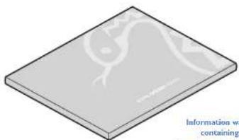
natural_image
Isometric view of a flat rectangular plate with a faint internal line drawing (no text or symbols)DDX-CAM DisplayPort option

DDX-CAM DVI option

DDX-CAM VGA option


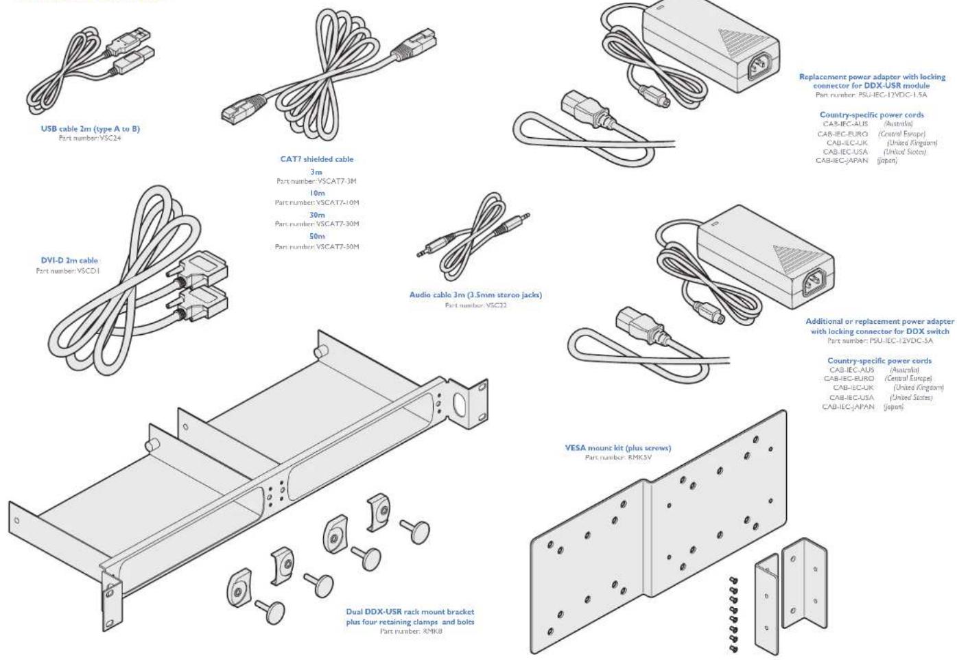
OPTIONAL EXTRAS

Installation
LOCATIONS
Please consider the following important points when planning the position of the AdderView DDX modules:
- If used, position the DDX switch in a central position that serves the host computer systems and user modules without exceeding the maximum link lengths. It will also require a source of mains power.
- Situate each DDX-USR module close to the peripherals to which it will be connected and near to a source of mains power.
- Consult the precautions listed within the Safety information section.

CONNECTIONS
Connections do not need to be carried out in the order given within this guide, however, where possible connect the power in as a final step. Connections are split into the following three areas:
• Computer connections - a DDX-CAM module links to each host computer.
- Switch connections - when used, a DDX switch unit sits at the heart of the system.
- Console connections - the peripherals (keyboard, display, etc.) connect to DDX-USR modules.
Computer connections: Video
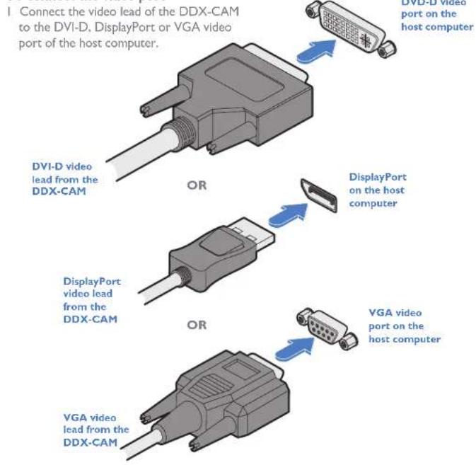
Three types of DDX-CAM modules are available:
DVI-D and USB or DisplayPort and USB or VGA and USB.
If a computer has more than one video output, use additional DDX-CAM modules to separately link the additional video stream(s) with other ports on the DDX switch.
To connect the video port
Computer connections: USB
Each DDX-CAM module requires a single USB connection to the computer. This provides essential power for the DDX-CAM module in addition to the USB signals. Each DDX-USR module acts as a USB 2.0 hub and thus provides four sockets for peripherals.
To connect the USB port
Connect the USB cable of the DDX-CAM module to a vacant USB socket on your host computer.

Computer connections: Data link
Each DDX-CAM module is linked via a shielded (S/FTP or S/STP) CAT6a or CAT7 cable either to a central DDX switch module or directly to a DDX-USR module (for a single system installation).
Maximum link cable lengths:
- DDX-CAM to DDX switch - 10 metres (32 feet) maximum.
- DDX-CAM to DDX-USR module - 50 metres (164 feet) maximum.
To link the DDX-CAM module
I Connect the RJ-45 plug of the link cable to the socket located at the end of the DDX-CAM module.

Switch (DDX10) connections: Computer links
The host computer links are made to the sockets on the rear panel of the DDX switch.
To connect a computer link
Connect a shielded (S/FTP or S/STP) CAT6a or CAT7 cable (10m maximum) from the remote DDX-CAM computer module to a vacant RJ-45 socket (sockets 1 to 8, by default) on the rear panel of the DDX10 switch.

These are NOT Ethernet/network ports and must NEVER be connected to any networking equipment.
Shielded CAT6a or CAT7 link from a remote DDX-CAM computer module

IMPORTANT: Always ensure you are using shielded cables.
Reallocating ports
By default the DDX10 switch provides 8 computer ports and 2 user ports along its rear panel. If necessary, these standard arrangements can be changed. See Reallocating ports.
Switch (DDX10) connections: User console links
The user console links are made via the sockets on the rear panel of the DDX switch.
To connect a user console link
Connect a shielded (S/FTP or S/STP) CAT6a or CAT7 cable (50m maximum) from the remote DDX-USR module to a vacant RJ-45 socket (sockets 9 and 10, by default) on the rear panel of the DDX10 switch.

Shielded CAT6a or CAT7 link from a remote DDX-USR module
IMPORTANT: Always ensure you are using shielded cables.

These are NOT Ethernet/network ports and must NEVER be connected to any networking equipment.
Switch (DDX30) connections: Computer links
The host computer links are made to the sockets on the rear panel of the DDX switch.
To connect a computer link
Connect a shielded (S/FTP or S/STP) CAT6a or CAT7 cable (10m maximum) from the remote DDX-CAM computer module to a vacant RJ-45 socket on the rear panel of the DDX30 switch.

These are NOT Ethernet/network ports and must NEVER be connected to any networking equipment.
Shielded CAT6a or CAT7 link from a remote DDX-CAM computer module

IMPORTANT: Always ensure you are using shielded cables.
Reallocating ports
By default the DDX30 switch provides 20 computer ports along its rear panel and 10 user ports along its front panel. If necessary, these standard arrangements can be changed. See Reallocating ports.
Switch (DDX30) connections: User console links
The user console links are made via the sockets at the front of the DDX switch.
To connect a user console link
Connect a shielded (S/FTP or S/STP) CAT6a or CAT7 cable (50m maximum) from the remote DDX-USR module to a vacant RJ-45 socket on the front panel of the DDX30 switch.

Shielded CAT6a or CAT7 link from a remote DDX-USR module
IMPORTANT: Always ensure you are using shielded cables.

These are NOT Ethernet/network ports and must NEVER be connected to any networking equipment.
Switch connections: Network link
All system configuration is carried out via an Ethernet link, allowing adjustments to be made by authorized admin users located next to the DDX unit, or anywhere. The autosensing network port can determine between 10, 100Mbps or 1Gbps links and can also adjust to straight or cross-over cables.
To connect a network link
I Connect the CATx cable from an Ethernet switch or from a local computer.
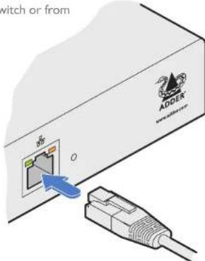
From a network switch or nearby computer
Switch connections: Options port
The options port is reserved for future use.

Switch connections: Power
Each DDX switch is supplied with a single power adapter but offers the facility to use a second input in order to provide operational redundancy. The DDX unit can operate perfectly well from a single power adapter operating alone. When two adapters are connected, the unit will spread its load between them; should one power input fail, 100% of the load will be transferred to the other power adapter without a break in operation. Remote checking of the power inputs is possible at any time via the browser interface - see Maintenance > Diagnostics for details.
There is no on/off switch on the DDX unit, so operation begins as soon as power is applied at either port.
To connect the power adapter
1 Attach the output plug of the supplied power adapter to either power input socket on the left side of the rear panel.

2 Connect the IEC connector of the supplied country-specific power cord to the socket of the power adapter.

natural_image
Diagram of an electrical outlet connected to a plug, showing internal components without any text or symbols.3 Connect the power cord to a nearby main supply socket.
4 Where power redundancy is required, repeat steps 1 to 3 for a second power adapter.
To disconnect the power adapter
I Isolate the power adapter from the mains supply.
Note: If you are replacing one of dual power adapters during operation, it is not necessary to also remove power from the other adapter.
2 Grasp the outer body of the power adapter plug where it connects with the module.
3 Gently pull the body of the outer plug away from the module. As the body of the plug slides back, it will release from the socket and you can fully withdraw the whole plug.
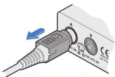
Gently pull back the plug outer body to release the lock
IMPORTANT: Please read and adhere to the electrical safety information given within the Safety information section of this guide. In particular, do not use an unearthed power socket or extension cable.
Note: Both the modules and the power supplies generate heat when in operation and will become warm to the touch. Do not enclose them or place them in locations where air cannot circulate to cool the equipment. Do not operate the equipment in ambient temperatures exceeding 40 degrees Centigrade. Do not place the products in contact with equipment whose surface temperature exceeds 40 degrees Centigrade.
Console connections: Video
A Single Link DVI-D port is provided on the rear panel of the user module.
The DDX-USR module supports one video display with pixel clocks up to 165MHz (equivalent to a maximum resolution of 1920 x 1200 at 60Hz - aka 'WUXGA').
If a second display is required to support a dual video installation, use another DDX-USR module to drive the second display, and combine the two user modules into a single Console within the DDX Matrix configuration application - See Configure > Computers.
To connect the video display
Connect the DVI-D video cable from your video display to the video output port on the rear panel of the user module.
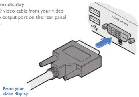
EDID management
The DDX switch provides a number of fixed EDID (Extended Display Identification Data) profiles that will suit a large number of video display configurations. If additional EDID definitions are required for your installation, you can clone new definitions from connected video displays and add these to the list of available definitions.
For details about cloning EDIDs from displays, see Add EDID.
For details about applying an EDID to a particular computer, see Configure > Computers > Transmitters.
DDX-USR module switches
The two switches on the DDX-USR module are reserved for future use and must both remain in the OFF position.
Console connections: USB
The DDX-USR module contains a USB hub that can support up to four v1.1 or v2.0 USB devices (in any combination). All four USB sockets, two on the front panel and two on the rear, are identical in operation.
Note: In multi-head installations, the USB devices must be attached only to the DDX-USR module that drives the main display.
To connect USB devices
I Connect your USB keyboard and mouse to any of the four sockets distributed on the front and rear panels of the user module.

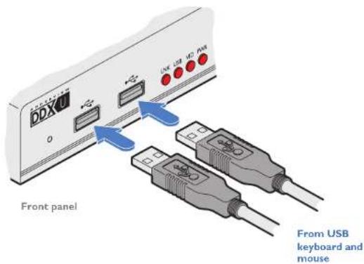
Console connections: Audio
The DDX-USR module supports stereo speakers, headphones and also a microphone port. All audio devices are presented at the linked host computer as USB audio devices. Note: In multi-head installations, the audio devices must be attached only to the DDX-USR module that drives the main display.
To connect your speakers
Connect your speakers to the audio line out socket on the user module rear panel.

To connect your headphones/microphone
I Connect your headphones to the socket labeled on the user module front panel.
2 Connect your microphone to the socket labeled on the user module front panel.

Console connections: Data link
Each DDX-USR module is linked via shielded (S/FTP or S/STP) CAT6a or CAT7 cable either to a central DDX switch module or directly to a DDX-CAM module (for a single system installation) - do not exceed 50 metres (164 feet).
To link the DDX-USR module
Connect a shielded (S/FTP or S/STP) CAT6a or CAT7 cable to the LINK socket on the rear panel of the DDX-USR module. Connect the other end of the cable to either a DDX switch or directly to a DDX-CAM computer module.
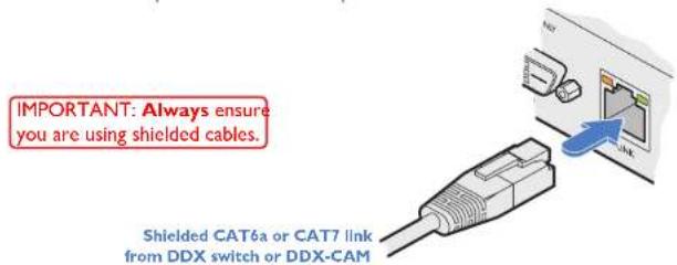

This is NOT an Ethernet/network port and must NEVER be connected to any networking equipment.
Console connections: Options port
The options port is reserved for future use.
Console connections: Power
There is no on/off switch on the DDX-USR module, so operation begins as soon as power is applied. The supplied power adapter uses a locking-type plug to help prevent accidental disconnections; please follow the instructions given right whenever disconnecting a power adapter.
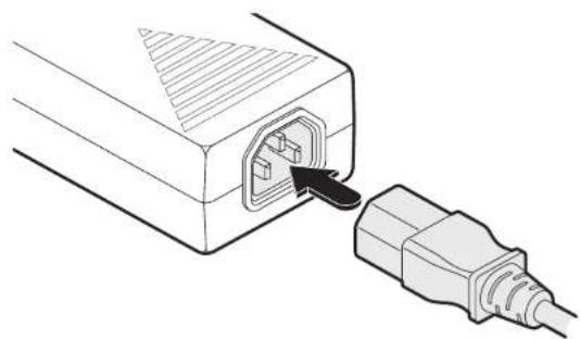
To connect the power adapter
1 Attach the output plug of the supplied power adapter to the power input socket on the rear panel of the DDX-USR module.

2 Connect the IEC connector of the supplied country-specific power cord to the socket of the power adapter.
natural_image
Line drawing of an electrical plug inserted into a socket (no text or symbols)3 Connect the power cord to a nearby main supply socket.
To disconnect the power adapter
I Isolate the power adapter from the mains supply.
2 Grasp the outer body of the power adapter plug where it connects with the module.
3 Gently pull the body of the outer plug away from the module. As the body of the plug slides back, it will release from the socket and you can fully withdraw the whole plug.

natural_image
Close-up of a white electrical plug with a blue arrow pointing to its socket (no visible text or symbols)Gently pull back the plug outer body to release the lock
IMPORTANT: Please read and adhere to the electrical safety information given within the Safety information section of this guide. In particular, do not use an unearthed power socket or extension cable.
Note: Both the modules and the power supplies generate heat when in operation and will become warm to the touch. Do not enclose them or place them in locations where air cannot circulate to cool the equipment. Do not operate the equipment in ambient temperatures exceeding 40 degrees Centigrade. Do not place the products in contact with equipment whose surface temperature exceeds 40 degrees Centigrade.

Configuration
ACCESSING DDX MATRIX
DDX switches are configured via their network connections using an intuitive browser-based application, called DDX Matrix. This secure, password protected application is accessible by any authorized user, located anywhere. The DDX switch can also be accessed via cross origin resource sharing (CORS). This allows interaction in a browser from a different web application. The API is served in a YAML format which can be found at http(s):/
To access DDX Matrix
I Use a computer that is directly or indirectly (i.e. via a network switch) connected to the DDX switch. If you need to make a temporary connection, see right
2 Run a web browser on your computer and enter the IP address of the DDX switch. The DDX switch uses the Universal Plug and Play (UPnP) protocol for Windows, or Bonjour (mDNS-SD) protocol for Mac and Linux, to contact a valid DHCP server to determine a suitable IP address. If a DHCP server cannot be located then the switch will automatically fall back to a static IP address of 192.168.1.22. This address selection system can be configured later.
Whichever method the switch uses, the initial IP address can be discovered either:
- Using the Windows network browser (of a computer connected to the same sub network or directly to the switch), or
- In the lower right corner of the OSD screen (of a console connected to one of the user ports) see Viewing the OSD. Note: For security, DDX Matrix uses HTTPS by default with a self-signed certificate - Please ignore any warnings that may be displayed by your web browser.
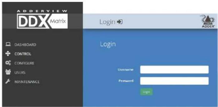
3 If requested, enter your username and password to log on.
Note: The default username and password are admin and password respectively.
The opening page of the DDX Matrix should be displayed:
To temporarily connect a computer to the network port
If you need to make a temporary connection for configuration purposes, use a standard patch cable (crossover or straight connections are both supported) to link the Ethernet 10/100 network port (□□□□□□□□□□□□□□□□□□□□□□□□□□□□□□□□□□□□□□□□□□□□□□□□□□□□□□□□□□□□□□□□□□□□□□□□□□□□□□□□□□□□□□□□□□□□□□□□□□□□ □ □ □ □ □ □ □ □ □ □ □ □ □ □ □ □ □ □ □ □ □ □ □ □ □ □ □ □ □ □ □ □ □ □ □ □ □ □ □ □ □ □ □ □ □ □ □ □ □ □ ▢ ▢ ▢ ▢ ▢ ▢ ▢ ▢ ▢ ▢ ▢ ▢ ▢ ▢ ▢ ▢ ▢ ▢ ▢ ▢ ▢ ▢ ▢ ▢ ▢ ▢ ▢ ▢ ▢ ▢ ▢ ▢ ▢ ▢ ▢ ▢ ▢ ▢ ▢ ▢ ▢ ▢ ▢ ▢ ▢ ▢ ▢ ▢ ▢ ▢ ▩

natural_image
Illustration of a network switch with an ADDER logo and cable connector (no text or symbols on the device itself)Temporary link from your computer
USING DDX MATRIX
The Dashboard page
Once you have successfully logged in, DDX Matrix will show the dashboard page to provide a general overview of your DDX installation. You can also re-display this page by clicking the Dashboard entry in the menu:

Note: It is not possible to remain logged in for more than 24 hours; after the webUI token has expired, you will need to log in again.
Quick guide to creating a new installation
When creating a new DDX installation there are various configuration tasks that need to be completed within DDX Matrix. This page provides a recommended 'to do list' of the stages that you need to perform.
Primary tasks
- Configure the networking details for the DDX switch.
- Ensure that the EDID definitions are appropriate for your installation. If additional EDID definitions are required for your installation, you can clone new definitions from connected video displays and add these to the list of available definitions.
- Add the required consoles (either before or after they are connected). By default the DDX switch provides 20 computer ports along its rear panel and 10 user ports along its front panel. If necessary, these standard arrangements can be changed to suit your installation.
• Determine the access permissions for each console. - Add your computers (either before or after they are connected).
- Add the users and define their login details. See The Users Page
Secondary tasks
- Optionally make changes to the OSD settings.
- Add description and location details for the switch.
See Configure > Central Switch > Network See Configure > Central Switch > Manage EDIDs
See Add EDID See Configure > Consoles
See Reallocating ports See Access permissions See Configure > Computers
See Configure > Central Switch > OSD Settings See Configure > Central Switch > General
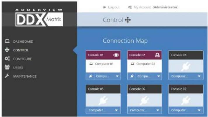
The Control page
The Control page provides a Connection map that allows the admin user to view and affect how consoles are connected to the various computers. This page is particularly useful when managing video-only installations.

Connection preset
You can optionally record and recall connection combinations that you often use between various transmitters and receivers as a preset.
To record your preset: Set up the required combination of links between transmitters and receivers (including any preferred Access Permissions), and then click the green Save as Preset' option.
Note: You can add or amend the connection preferences of any console (that will be enacted whenever this overall 'Connect to Preset' option is clicked) within the Add/Edit pages of the required console. See Preset Connection at Configure > Consoles > Add new entry or Configure > Consoles > Edit an entry.
To use your preset: Click the amber 'Connect to Preset' option.
To connect a console
I Click the down arrow on the console entry to reveal the list of computers that it is authorized to access.

2 Click the appropriate connection icon adjacent to the required computer:
- View only - console user can view a computer's output but not alter it.
• Shared access - console user can view and control a computer along with other consoles, - Exclusive - multiple console users can view a computer but only one can control it,
or
- Private - console user can view and control the computer privately while other users are locked out. For further details, see Access permissions.
3 You can change the connection method at any time by clicking the down arrow again and choosing an alternative connection option.
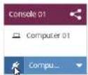
To disconnect a console
I Click the 📄 button in the lower left corner of the console entry that you wish to disconnect.
The Configure pages
The Configure menu option expands when clicked to reveal three sub-sections:
• Central Switch - settings related directly to the DDX switch.
- Consoles - settings related to the DDX-USR modules and their connected peripherals.
• Computers - settings related to the DDX-CAM modules and their host computers.
![ADDerview DDX Matrix Configure Central Switch / General Description: Windows test Location System Default ID: System - DDX-101 - 1920x1068 HD1020 @ 639 Ignore Firmware Mismatch Manage Time Automatically Use Current PC Time: 11:41:48 Time Zone: [UTC] Dublin, Edinburgh, London, London This item is shown only when the Maintenance > Settings > Web UI Mode is set to Advanced.](/content/2026/05/868200/images/4e4a8fdb234cec533953022c244497dcf122072c070d9f0f387d71f4734a61ce.jpg)
Central Switch > General
Basic settings for the DDX switch. Description/Location are most useful when multiple DDX installations are being managed; labelling each installation as you go is a good habit to get into: - System Default EDID - determines the default EDID to use for the installation.
- Ignore Firmware Mismatch - when set to On, this overrides the checks that are made to ensure all modules are running compatible firmware versions. This override should be used in exceptional circumstances only.
- Manage Time Automatically – when set to ON the current time and timezone will be obtained via the configured NTP & DHCP servers.
- Use Current PCTime - when managing time manually, the system time will be synced to that from the local computer.
- Timezone - when managing time manually or running without DHCP, allows you to declare which timezone you are in.
When the Maintenance > Settings > Web UI Mode is set to Advanced, an extra Versions block is displayed below the General section for diagnostic purposes:
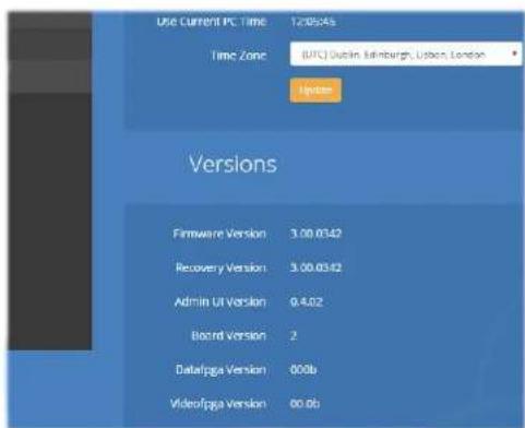
- Firmware Version - shows the firmware version of the DDX switch.
- Recovery Version - shows the version of the DDX switch recovery image.
- Admin UI Version - shows the version of the DDX Matrix admin user interface.
- Board Version - shows the version of the main DDX motherboard.
- Datafpga Version - shows the version of the gate array chip that handles data throughput.
- Videofpga Version - shows the version of the gate array chip that handles video signals.

Central Switch > Network
All of the key settings for the network capabilities of the DDX switch are here:
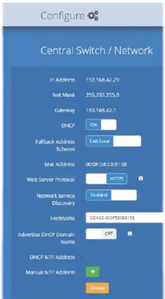
- IP Address - shows the current IP address for the switch.
- Net Mask - shows the current subnet mask to accompany the IP address.
- Gateway - shows the current address for a gateway device.
- DHCP and (Fallback) Address Scheme - using these two options you can determine how the IP address of the DDX switch should be derived. See below.
- MAC Address - displays the unique (and fixed) MAC address for the switch.
- Web Server Protocol - allows a change to the use of insecure HTTP for web admin - switch reboot required. IMPORTANT: Do not set this option to HTTP when the switch is connected to external networks.
- Network Service Discovery - when set to Disabled, the switch will not announce its presence on the network and will not be discoverable using the Windows network browser on a network-connected computer.
- Hostname - provides a way to access the DDX Matrix by using this hostname together with the domain name (http(s)://
. ), removing the need to know the IP address. - Advertise DHCP Domain Name - when set to Off, the DDX switch will use its locally applied domain name in order to appear in the Apple® Bonjour (mDNS-SD) service (this is necessary on some incorrectly configured networks that use the local top-level domain). When set to On, the DDX switch will broadcast its DHCP-supplied name to the Bonjour service.
- DHCP NTP Address - when DHCP is On, this area lists the addresses of time servers being used. This service is only supported if the option 42 NTP server is enabled on the DHCP server. If the alternate timezone option 4 is in use, the IP address of the NTP server will not be displayed.
- Manual NTP Address - allows you to enter the static IP addresses of up to five NTP servers (an average of the time feeds from the servers is taken).
DHCP and (Fallback) Address Scheme
These two options together determine the manner in which the IP address of the DDX switch is configured. If DHCP is set to ON and is available via the network, then the IP address will be set by DHCP.
If DHCP is set to OFF or is unavailable, then the (Fallback) Address Scheme setting comes into play. Whenever the Static option is chosen, you will be able to enter the required IP Address, Net Mask and Gateway options.
This summary shows the combination of settings and their effect on the IP address of the DDX switch

Central Switch > OSD Settings
Options related to the on screen display are presented in this section:
Log out
My Account (Administrator)

- Thumbnails - when set to Off, this option will hide the thumbnail views of each computer within each user's OSD main page.
- Auto Layout - when set to Off, this option will maintain a 5x5 grid for the displayed computers within the OSD main page, regardless of the number of available computers. When set to On, the OSD view grid will be re-scaled accordingly.
- Use Full Grid - when set to On, if you have 4, 9 or 16 computers connected, the OSD will use the bottom right portion of the screen as a square computer thumbnail, instead of reserving it for the system information. A small tab appears in the top right corner of the OSD if "Show System Info" is On, showing the IP address and an icon denoting any compatibility issues (green tick for no issues, yellow warning for upgrade recommended and a red warning for upgrade required). Note: This option will be hidden if Auto Layout is set to Off.
- Display System Info - when set to On, the current IP address and firmware version details for the DDX switch will be shown in the lower right corner of the OSD, or the IP address and firmware icon in the top right corner of the OSD. Note: Disabling 'Display System Info' will remove the IP address from the OSD. When 'Use Full Grid' is enabled, this option will also suppress all firmware version mismatch warnings.
- Display Date and Time - when set to On, the current date and time are displayed on the OSD menu.
- Background Brightness - determines the brightness of the OSD thumbnail views when the mouse is not hovering over them. Five settings are available, from 100% down to 20%. If set to 100% then all thumbnails remain at full brightness all of the time. Whereas, at 20% all thumbnails will darken until the mouse hovers over one of them, at which point it will come to full brightness to clearly highlight it against all the others.
- EDID - optionally allows you to determine a video resolution to use when displaying the OSD. For instance, if you have a 19" monitor that can only display 1024x768 then by changing this setting to 1024x768 you can match the OSD to the screen resolution. Firmware versions below v3.0 will only display the OSD at a resolution of 1920x1080. After this setting has been changed, the system will reboot automatically.
WARNING: This is a global setting and will be applied to all the monitors connected to the system. Before making changes, ensure that all your monitors can support this video resolution. If you have different sized monitors, this option should be set to the video resolution of the smallest monitor to ensure that you can bring up the OSD on all the monitors connected to your system.
Central Switch > Manage EDIDs
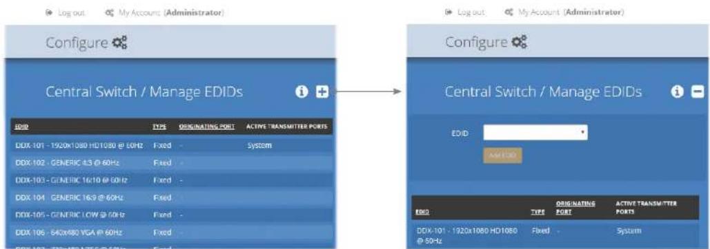
This page lists the EDID (Extended Display Identification Data) profiles that are currently available:
- EDID - shows the resolutions and refresh rates for all profiles that are currently stored.
- Type - indicates where each EDID profile originated: Fixed EDIDs are included within the switch firmware and cannot be removed. User EDIDs are those that have been cloned from particular video displays attached to DDX-USR modules - these can be deleted if required. On the main Central Switch > General page you can select the 'Default System EDID' from the list of fixed and user EDIDs.
- Originating Port - indicates which switch port supplied each user EDID.
• Active Transmitter Ports - indicates which transmitters (if any) are currently using each EDID.
Note: The DDX switch will modify the EDID, if a Dual link monitor is connected, to list only the video resolutions that it is capable of supporting.
Add EDID
If additional EDID definitions are required for your installation, you can clone new definitions from connected video displays and add these to the list of available definitions.
Click the [+] icon to begin collecting a new EDID from a display attached (via a DDX-USR module) to one of the switch ports.
Click the EDID dropdown list and choose the appropriate receiver (DDX-USR module) from which you wish to clone a new EDID profile. Then click the Add EDID button.
For details about applying an EDID to a particular computer, see Configure > Computers > Transmitters.
Configure > Consoles
A Console is a collective term for a set of peripheral devices arranged around one or more DDX-USR modules. This page lists all registered consoles:
Log out


![Configure Consoles Click a heading to reorder the whole list in ascending or descending order according to the entries within the chosen column. NAME DESCRIPTION PORTS ISO MOUSE LAUNCH CONNECTED COMPUTER CURRENT ACCESS MODE Console 01 Console on Port 21 [21] On - Console 02 Console on Port 22 [22] On - Console 03 Console on Port 23 [23] On - Console 04 Console on Port 24 [24] On - Console 05 Console on Port 25 [25] On - Console 06 Console on Port 26 [26] On - Console 07 Console on Port 27 [27] On - Online Selected](/content/2026/05/868200/images/677b47934b967895b5c4d876779bf7e50a1be7216f25a762c68784395cd86f91.jpg)
In addition to the Name and Description, other columns provide the following details and options for each console entry:
- Ports - each DDX-USR module connects to a single port on the DDX switch. This column lists the port(s) used by the DDX-USR module(s) associated with each console. Two or more DDX-USR modules can be combined to form multi-head consoles, each connecting to separate ports.
Note: For consoles with multiple displays (multi-head), additional user console ports are required. If there are no spare user console ports available then any unused computer ports on the rear panel can be deleted in order to free them up as spares. See Reallocating ports. - OSD Mouse Launch - when set to On, allows the console user to invoke the on Screen Display by holding down their center mouse button and then clicking the right button.
- Connected Computer - shows to which computer the console is currently connected.
- Current Access Mode - indicates how the console is currently connected to the listed computer: View only, = Shared access, Exclusive, Private
- Tick box - Allows you to tick all required console entries and then remove them collectively using the Delete Selected button.

Add new
Click the [+] icon to begin adding a new console, either before or after connecting the DDX-USR module(s). See Configure > Consoles > Add new entry

Edit
Click an entry to view/edit its details. See Configure > Consoles > Edit an entry
Configure > Consoles > Add new entry
Click the [+] icon within the Configure > Consoles list to display this page and begin adding a new console, either before or after connecting the DDX-USR module(s):

Add new
- Name - the main identifier for the new console.
• Description - a further opportunity to add more information. - OSD Mouse Launch - when set to On, allows the console user to invoke the on Screen Display by holding down their center mouse button and then clicking the right button.
- OSD Touchscreen Launch - when set to On (and when a touchscreen is being used at the console), a translucent launch icon is overlaid onto the primary screen and can be dragged to an appropriate location. When the icon is tapped, the OSD will be launched as normal.
- OSD Hotkey Modifiers - allows you to alter the standard hotkey modifiers that, together with the OSD Launch Key cause the OSD to be displayed on the console.
- OSD Launch Key - allows you to alter the standard key that, together with the OSD Hotkey Modifiers, causes the OSD to be displayed on the console.
- VCP Key - determines the key that, together with the OSD Hotkey Modifiers, causes the Virtual Control Panel to be displayed. The Virtual Control Panel allows users to adjust various aspects of their video image (when viewing an analog VGA source). See Using the Virtual Control Panel to adjust VGA inputs.
- Keyboard Layout - determines the overall keyboard layout to use with the console.
- Port - add the port number (located on the main DDX switch) used by the DDX-USR module associated with this console. For multi-head consoles, ensure that the port used by the primary DDX-USR module (the one that has the primary display and peripherals attached) is the first one to be defined. If a chosen port is already used, a warning will be displayed, see Reallocating ports.
- Access Permissions - click the [+] button to select one or more computers that this console will be permitted to access. For each computer choose the appropriate access permissions (see Access permissions): View only, = Shared access, Exclusive, Private
- Preset Connection - allows you to choose which computer this console should connect with (and which Access Permissions should be used) when the Connect to Preset option is clicked on the Control page. Any changes made here will modify any existing settings for this console which may already exist within the overall preset.
- Add Console - click to save your settings.
Configure > Consoles > Edit an entry
Click on an entry within the Configure > Consoles list to display this page. Here you can edit the configuration details for a chosen console.


Edit
- Name - the main identifier for the console.
• Description - a further opportunity to add more information about the console. - OSD Mouse Launch - when set to On, allows the console user to invoke the on Screen Display by holding down their center mouse button and then clicking the right button.
- OSD Touchscreen Launch - when set to On (and when a touchscreen is being used at the console), a translucent launch icon is overlaid onto the primary screen and can be dragged to an appropriate location. When the icon is tapped, the OSD will be launched as normal.
- OSD Hotkey Modifiers - allows you to alter the standard hotkey modifiers that, together with the OSD Launch Key cause the OSD to be displayed on the console.
- OSD Launch Key - allows you to alter the standard key that, together with the OSD Hotkey Modifiers, causes the OSD to be displayed on the console.
- VCP Key - determines the key that, together with the OSD Hotkey Modifiers, causes the Virtual Control Panel to be displayed. See also page 38.
- Keyboard Layout - determines the overall console keyboard layout.
- Ports - shows the user port number(s) (located on the main DDX switch) used by the DDX-USR module(s) associated with this console. For multi-head consoles, ensure that the port used by the primary DDX-USR module (the one that has the primary display and peripherals attached) is the first one to be defined. If a chosen port is already used, a warning will be displayed, see Reallocating ports.
- Access Permissions - choose which computers this console is permitted to access:
• View only - console user can view a computer's output but not alter it.
- Shared access - console user can view and control a computer along with other consoles,
- Exclusive - multiple console users can view a computer but only one can control it, or
- Private - console user can view and control the computer privately while other users are locked out.
For further details, see Access permissions.
- Preset Connection - allows you to choose which computer this console should connect with (and which Access Permissions should be used) when the Connect to Preset option is clicked on the Control page. Any changes made here will modify any existing settings for this console which may already exist within the overall preset.
When you have made your changes, click the Update button.
Configure > Consoles > Receivers
At the heart of each console (the collective term for a set of peripherals connected to the DDX system) is a receiver called a DDX-USR module.

This page shows various details for each DDX-USR module:
- Firmware - the current internal software version for each DDX-USR module.
- Monitor No - an index number for each video display. The first monitor for any console will be indexed as '1'. Where a console has more than one video display associated with it (by using additional DDX-USR modules), this column will show '2', '3', etc. against the secondary, tertiary, etc. DDX-USR module(s).
- Monitor model - indicates the video display model as reported to the DDX-USR module to which it is connected.
- Unique ID - (shown only when the Maintenance > Settings > Web UI Mode is set to Advanced) this column displays the unique identifier hardwired into every DDX-USR module.
Click a receiver entry to view the configuration details of the DDX switch port to which it is connected.
Within this page it is possible to reboot and/or recover a receiver.
Recovering a receiver
This option (shown only when the Maintenance > Settings > Web UI Mode is set to Advanced) is used to reprogram a receiver that has failed during a firmware upgrade. Once the Recover Receiver button is clicked, you will be asked to power cycle the respective receiver, whereupon it will boot up into recovery mode. Then you will asked to click a Reprogram button to commence the operation.
Configure > Computers
This page lists the computer systems that are connected to the DDX switch unit via individual DDX-CAM modules:
![Configure Computers Click a heading to reorder the whole list in ascending or descending order according to the entries within the chosen column. NUMBERS NAME DESCRIPTION PORTS THUMANIR PRIMARY CONSOLE CONNECTED CONSULES CURRENT ACCESS MODE 1 Computer 01 Computer description [1] ✓ - Console 01 2 Computer 02 Computer description [2] ✓ - Console 02 3 Computer 03 Computer description [3] ✓ - - 4 Computer 04 Computer description [4] ✓ - - 5 Computer 05 Computer description [5] ✓ - - 6 Computer 06 Computer description [6] ✓ - - 7 Computer 07 Computer description [7] ✓ - - 19 Computer 19 Computer description [19] ✓ - - 20 Computer 20 Computer description [20] ✓ - - -](/content/2026/05/868200/images/1a1fe316881526a56ed640a4054ea8945ba984a83660db65e977143e14aa0fcb.jpg)
In addition to the Name and Description, the columns also provide the following useful details for each computer entry:
- Port(s) - each DDX-CAM module connects to a single port on the DDX switch. This column lists the port(s) used by the DDX-CAM module(s) associated with each computer. Two or more DDX-CAM modules can be combined to support extra displays (multi-head), each connecting to a separate port. Three of the user console ports (21 to 23) can be changed into computer ports, if there are fewer user consoles within your installation. See Reallocating ports.
- Thumbnail - indicates whether a thumbnail image of the computer's video output will be shown on the OSD screen for each user. If disabled (unticked), a black image will be shown in the OSD screen.
• Primary Console - indicates the console that currently has control of the computer. - Connected Consoles - lists all consoles to which each computer is attached.
- Current Access Mode - indicates how the computer is currently being accessed by the listed console: = View only, = Shared access, Exclusive, Private
- Tick box - Allows you to tick all required computer entries and then remove them collectively using the Delete Selected button.

Add new
Click the [^+] icon to begin adding a new computer, either before or after connecting the DDX-CAM module(s):
- Name - the main identifier for the new computer.
• Description - a further opportunity to add more information about the computer. - Computer Number - provides a list of the remaining vacant computer numbers that you can associate with your new entry. The chosen number will determine the position of this computer in the OSD screen and also the hotkey (Ctrl+Alt+n) used to access it. You can swap the number used with other computers within the edit page.
- Ports - Add one or more port numbers used by the DDX-CAM module(s) associated with this computer.
Edit
Click an entry to view/edit its details and options.
See Configure > Computers > Edit an entry
Configure > Computers > Edit an entry
This page allows you to edit the configuration details for a chosen computer.

Edit
- Name - the main identifier for the computer.
• Description - a further opportunity to add more information about the computer. - Computer Number - displays a list of computer numbers (used and vacant) that you can associate with this entry. The chosen number will determine the position of this computer in the OSD screen and also the hotkey (Ctrl+Alt+n) used to access it. If you choose a computer number that is already used by another computer, then it and the existing number held by this computer will be swapped over:
- Port(s) - shows the one or more port numbers used by the DDX-CAM module(s) associated with this computer. For multi-head computers, ensure that the port used by the primary DDX-CAM module (the one linked to the primary video output) is the first one in the list. Three of the user console ports (21 to 23) can be changed into computer ports, if there are fewer user consoles within your installation. See Reallocating ports
- Thumbnail - indicates whether or not a thumbnail view of this computer's video output should be shown OSD screen for each user.
- Primary Console - indicates the primary console that is connected to this computer.
- Connected Consoles - indicates other consoles that are also connected to this computer.
- Current Access Mode - indicates the highest level access mode (e.g. View Only, Shared, Exclusive, etc.) that is currently being used for this computer.
- Transmitters - lists the transmitters (DDX-CAM modules) that are serving this computer.
When you have made your changes, click the Update button.
Configure > Computers > Transmitters
Each computer connects to a DDX-CAM transmitter module. This page lists each DDX-CAM module and their key details:
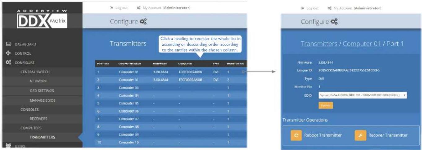
This page lists various details for each DDX-CAM module:
• Computer Name - the given name for each connected computer.
- Firmware - the current internal software version for each DDX-CAM module.
- Monitor No - an index number for each video display port. The first port for any computer will be indexed as '1'. Where a computer has more than one video display connected it (by using additional DDX-CAM modules), this column will show '2', '3', etc. against the secondary, tertiary, etc. DDX-CAM module(s).
- Unique ID - (shown only when the Maintenance > Settings > Web UI Mode is set to Advanced) this column displays the unique identifier hardwired into every DDX-CAM module.
Click a transmitter entry to view the configuration details of its port on the DDX switch. Within this page it is possible to reboot and/or recover a transmitter.
Applying a different EDID
If a computer needs to use an EDID profile that differs from the one being used as the default System EDID, use these steps:
I If necessary, clone the required EDID - see Add EDID.
2 View the Configure > Computers > Transmitters page and click on the required computer entry (to show the page above).
3 Select the appropriate entry from the EDID drop down list.
4 Click the Update button.
Recovering a transmitter
This option (shown only when the Maintenance > Settings > Web UI Mode is set to Advanced) is used to reprogram a transmitter that has failed during a firmware upgrade. Once the Recover Transmitter button is clicked, you will be asked to power cycle the respective transmitter, whereupon it will boot up into recovery mode. Then you will asked to click a Reprogram button to commence the operation.
Reallocating ports
By default the DDX switch provides 10 user console ports on its front panel and 20 computer ports along its rear panel, however, these designations are not fixed. If your installation requires a greater number of computers or has a need for more user consoles, you can alter the allocation of these standard ports to suit:
- Any of the 20 rear panel computer ports can be reallocated as user console ports, or
- Three of the front panel ports (labeled 21 to 23) can be used as computer ports.
To reallocate a port that is already being used
While creating (or editing) a computer or console entry, choose the required port. If the port is already being used, when you click the Update button, you will be presented with a warning such as the following:
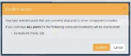
2 Click the Confirm button. The chosen port will first be de-allocated from its existing relationship and then paired to your device. The device that originally used the port will be left without a port allocation and will need separate attention.
Note: If you reallocate any port from a multi-head computer/console this will cause all ports associated with that computer/consoles to be de-allocated.
The Users page
This page lists all registered users and allows the admin user to add, edit and delete entries, as required.
Note: When changes are made to user details, you are recommended to make a backup file.

flowchart
graph TD
    A["Adderview DDX Matrix"] --> B["Users"]
    B --> C["Users"]
    C --> D["Users / Administrator"]
    D --> E["Change Password"]
    style A fill:#f9f,stroke:#333
    style B fill:#ccf,stroke:#333
    style C fill:#cfc,stroke:#333
    style D fill:#fcc,stroke:#333
    style E fill:#cff,stroke:#333
The Maintenance pages
The Maintenance section contains three pages: Diagnostics, System Operations and Settings.
Maintenance > Diagnostics
This page provides important feedback on power inputs (and switch Temperatures). The temperature information is displayed only when the Maintenance > Settings > Web UI Mode is set to Advanced.

This section lists the currently active ports, their uptime and status.
Maintenance > System Operations
This page provides a selection of important system operations that may be required at various times.

Recovering an unresponsive transmitter or receiver
If a firmware upgrade to a transmitter or receiver has failed, the unit may become unresponsive. If so, please follow the advice provided in other sections of this guide:
• Recovering a transmitter
- Recovering a receiver
Upgrade Firmware
Upgrades the firmwares of the DDX switch and all connected modules to the latest version. Confirmation is required once this button is clicked.
Note: On a fully populated switch with all the ports in use it will take an additional minute in order to apply the upgrade than a switch with only one or two ports in use.
If the switch is on its link local address and you have firmware below V3.0 when you upgrade the switch be aware that after the reboot a new link local address will be assigned. If the switch has firmware V3.0 or above the same link local address is used.
Backup
Saves a copy of the DDX Matrix system configuration to a file. Backup files are stored on the computer viewing DDX Matrix.
Sync Tx/Rx Firmware
Upgrades the firmwares of all connected modules to match that of the main switch. Confirmation is required once this button is clicked.
Note: Be sure that the DDX switch has the latest firmware installed before using this option.
Restore
Restores the DDX Matrix system configuration from a backup file. A file dialog will be displayed to allow you to choose the filename and location.
Note: In order to prevent an incorrect backup file being uploaded to the switch only backup files created with V3.0 and above firmware are restored on a V3.0 switch. Any backup file taken from a switch with 2.0 or less firmware will not be restored on a V3.0 switch.
Reboot System
Performs a complete reboot of the entire DDX system, including the switch and all modules. Confirmation is required once this button is clicked.
Factory Reset
Returns all DDX system configuration settings back to their factory defaults.
Maintenance > Settings
This page provides options related to the user interface. When you make a change, you need to click the Update button to save it.
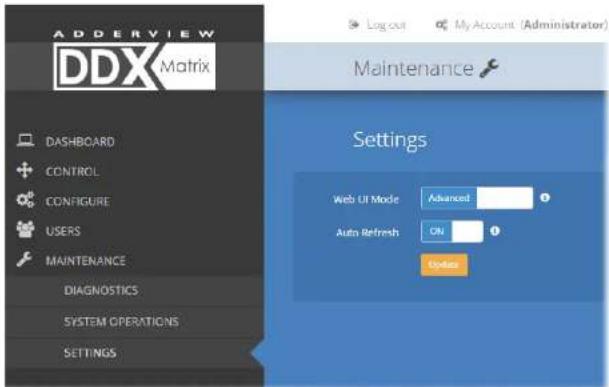
Web UI Mode
When this option is set to Advanced, extra details are shown on certain pages, such as:
- Configure > Central Switch > General
- Configure > Consoles > Receivers
- Configure > Computers > Transmitters
- Maintenance > Diagnostics
Auto Refresh
When this option is set to On, the Dashboard, Control and Diagnostic pages will automatically update their contents every few seconds.
Update
Click this button to save and enact any changes made to options.
RESETTING AND RECOVERING
There may be rare occasions when the main switch or a module needs to be given a hard reset. The DDX switch and DDX-USR module both have concealed reset buttons for this purpose. You need to use a narrow implement (e.g. a straightened-out paper clip) to press-and-hold the recessed reset button on the front panel:
DDX switch
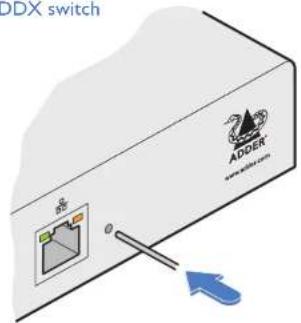
DDX switch > Boot into recovery image
This procedure may be necessary if an attempted firmware upgrade has failed. The switch will load the factory default configuration, requiring you to log-in using the factory default username/ password and a freshly determined IP address (see Accessing DDX Matrix). You will be required to accept a new temporary SSL certificate when accessing the web interface. Note: All configuration data (e.g. users, consoles, computers, networking, etc.) will be retained.
1 Press-and-hold the recessed reset button for ten seconds until the STS (Status) indicator begins to flash slowly.
2 Release the reset button. The STS indicator will go out and the switch will boot itself using the recovery image. The STS indicator will now begin to flash again to indicate that it is running from the recovery image (a red banner will also be shown at the top of the DDX Matrix screen).
3 When you are sure of operating conditions, such as having good power stability, proceed once again with the firmware upgrade.
DDX switch > Reset
This procedure may be necessary if the switch has become unresponsive. Note: All configuration data (e.g. users, consoles, computers, networking, etc.) will be retained.
I Press-and-release the recessed reset button. The switch will reboot.
DDX-USR module
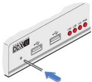
DDX-USR module > Boot into recovery mode
This procedure may be necessary if an attempted firmware upgrade has failed. For such a situation the DDX-USR module always retains a recovery image that will return the unit to a working condition, prior to reattempting a firmware upgrade.
Press-and-hold the recessed reset button for ten seconds until the PWR indicator begins to flash quickly.
2 Release the reset button.
3 When you are sure of operating conditions, such as having good power stability, proceed once again with the firmware upgrade.
DDX-USR module > Reset
This procedure may be necessary if a DDX-USR has become unresponsive.
I Press-and-release the recessed reset button. The DDX-USR module will reboot.
Recovering an unresponsive transmitter or receiver
If a firmware upgrade to a transmitter or receiver has failed, the unit may become unresponsive. If so, please follow the advice provided in other sections of this guide:
• Recovering a transmitter
• Recovering a receiver
Operation
The DDX system is designed to be transparent in operation. A simple OSD (On Screen Display) interface allows each user to view and select from the available host computers. Note: The default OSD resolution is 1920 x 1080. If your video display does not support this resolution, see Central Switch > OSD Settings to choose a setting that suits your screen.
VIEWING THE OSD
To view the OSD, either:
• From a console keyboard, press CTRL + ALT + M*, or
- From a console mouse, press and hold the center button and then press the right button*, or
- From a touchscreen, tap the translucent launch icon (if shown) on the touchscreen*.
The OSD will be displayed:
* OSD access settings
The precise functions or availability of the keyboard, mouse and/or touchscreen access methods are dependent on the settings within the Configure > Consoles page. See Configure > Consoles > Add a new entry or Configure > Consoles > Edit an entry.

Thumbnail images
The outputs of the available host computers will be displayed within live thumbnail images.
Note: If video is not available for a computer, or the Thumbnails option has been set to OFF, a black image will be shown. See Central Switch > OSD Settings.
Switch information
The additional information in the lower right corner, including the current IP address setting, firmware version and any current firmware upgrade warnings/errors, is displayed within the OSD screen, providing the Display System Info option is set to ON.
See Central Switch > OSD Settings.
continued
Choosing a computer
To choose a computer using the mouse
I Display the OSD from your console using any of the methods shown on the previous page.
2 Hover the mouse pointer over the required screen image. A set of popup connection icons will be displayed:
• View only - you can view a computer's output but not alter it,
- Shared access - you can view and control a computer along with other consoles,
- Exclusive - multiple users can view a computer but only one (the first to make connection) can control it, or
- Private - you can view and control the computer privately while other users are locked out.
For more details, see Access permissions.
Note: If an icon is grayed out, that access method is not available.
3 Click the required connection method. The video output from the chosen computer will be displayed full screen and you can use it as normal.
Note: When viewing the OSD, you can also click outside a computer thumbnail to return to your previous computer (with your last access permissions if still available).
To choose a computer using hotkeys (without viewing the OSD)
- Press and hold Ctrl + Alt and type the number of the required computer. The video output from the chosen computer will be displayed full screen and you can use it as normal.
Note: Shared access mode is always used when the computer choice is made via hotkeys.
Using the Virtual Control Panel to adjust VGA inputs
When video inputs are fed from analog VGA sources (via a DDX-CAM-VGA) it may be necessary to perform minor adjustments to achieve the best possible image; the Virtual Control Panel allows you to do this.
To adjust the image from an analog VGA input
I Display the OSD from your console.
2 Select the appropriate computer.
3 Press the following hotkey combination: CTRL + ALT + C to display the Virtual Control Panel.
4 Then:
- To change position of screen image: Use the keyboard arrow keys.
• To adjust the brightness: Use the + and- keys.
• To adjust the clock phase: Use the < and > keys.
- To reset to the default settings: Press the R key.
5 To return to normal operation: Press the Escape (Esc) key. Any changes made will be stored for this computer within your console and will be reapplied each time the computer is revisited.
USB Improvements
Version 2.0 of the DDX Switch firmware has the following improvements in USB support over the original v1.03:
- Touchscreens that advertise compatibility with windows 8 are now supported. Any touchscreens that use proprietary drivers or do not declare windows 8 support are not supported. Multiple touchscreens are now merged into the combined HID device that the transmitter reports.
• The Adder Free-Flow mouse reported by the CCS-PRO4 is now merged so as only one Free-Flow mouse is reported by the transmitter. Previously, if four receivers were connected to the CCS-PRO4, four different Free-Flow mice would be reported meaning that no other non-emulated USB device could be connected to the receivers. - Up to five non-emulated USB HID devices can be connected to the transmitter. The transmitter can support up to seven USB devices, but will always report a combined HID device for keyboard/mouse and touchscreen support, and an Audio device for speakers and microphone support.

USING AUDIO
The DDX system fully supports stereo audio, with all audio devices being presented at the linked host computer as USB audio devices. There are slight differences in audio operation between DDX devices acting in a simple extender arrangement (without the use of a DDX switch) and a full DDX matrix installation.
Using audio in a simple extender installation
The audio is presented to the computer's operating system as a USB headset with controls for input level, input mute, input AGC, sidetone level, sidetone mute, output level, output mute and output balance. The audio device is permanently presented to the computer when the DDX-CAM module powers up.
You can adjust the audio features using all of the standard operating system controls.
Note: Due to the architecture of the Codec, adjusting the input (microphone) level or muting the input (microphone) will also affect the sidetone level and mute.
Using audio in a full DDX matrix installation
Audio functionality is enabled by default on all computers. For multi-head computers, audio is only enabled for the primary transmitter, although two audio devices will be presented to the computer, one for each transmitter. For multi-head consoles, audio is only enabled for the primary receiver.
Managing audio in multi-user situations
- In all connection modes, the audio output of the computer is routed to the receiver from the transmitter.
- In View Only and Shared modes, the receiver input audio is ignored.
- In Exclusive and Private modes, the receiver input audio is routed to the transmitter.
Note: The above is equivalent to routing the output audio as per the video and the input audio as per the USB (except in View Only and Shared modes, where the input audio stream is ignored).
When viewing the OSD selection screen, input and output audio is suppressed.
The user who is currently in control of a computer can adjust the audio levels using the standard operating system audio features; their changes will affect the audio for all other users viewing the same computer. Additional users connected in View Mode, or additional Shared Access users who don't have control, can listen to the audio but at the volume dictated by the main user. As a user switches between machines, their audio levels are automatically adjusted to match their current connection.
INDICATORS
The DDX switches, the DDX-CAM and DDX-USR modules contain various indicators to provide you with status information.
DDX switch - Red front panel status indicators
The red status indicators on DDX switch front panels provide various key power and operation feedback:

flowchart
graph TD
    A["PWR A"] --> B["Power input A"]
    C["PWR B"] --> D["Power input B"]
    E["STS"] --> F["STS (Status)"]
    G["ERR"] --> H["ERR"]
    B --> I["This indicator will be on when power is supplied to power socket A"]
    D --> J["This indicator will be on when power is supplied to power socket B"]
    F --> K["On: Running primary firmware image\n1Hz flash: Running backup firmware image\n2Hz flash: Upgrade mode engaged"]
    H --> L["Flashing: Either, Power input failed or internal error - refer to the Maintenance > Diagnostics page for details or A firmware mismatch has been detected with one or more connected devices - refer to the Dashboard page for details"]
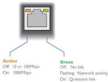
DDX switch - Green and amber network status indicators
The green and amber status indicators on the network link port provide further status information:
DDX-USR module - Green and amber status indicators
The green and amber indicators on the link port of each DDX-USR (console/user) module provide the following status information:

natural_image
Simple diagram of a computer interface with two ports and connecting lines (no text or symbols)Amber
Off: No power
Slow flashing: Power present but either no video or video not locked
On: Power present and video locked
Green
Off: No power
Flashing: Power present but no data link
On: Power present and link established
DDX-USR module - Red front panel status indicators
The red indicators on the front panel of each DDX-USR (console/user) module provide the following status information:

flowchart
graph TD
    A["LNK"] --> B["Off: No power or no link"]
    A --> C["USB"]
    A --> D["Off: No power or no active USB connection"]
    A --> E["Flashing: Switch refused link connection due to incompatible firmware versions"]
    A --> F["On: Link established"]
    A --> G["VID"]
    A --> H["PWR"]
    G --> I["Off: No power present or the video is not locked"]
    G --> J["Off: Power present and video locked"]
    H --> K["Off: No power present\nSlow flashing: A firmware upgrade is being forced by the DDX switch"]
    H --> L["Fast flashing: Receiver in USB recovery mode"]
    H --> M["On: Power present"]
Special condition
PWR on, Amber flashing and Green off: Software fault requiring the DDX-USR module to be recovered. See Configure > Consoles > Receivers.
DDX-CAM module - Green and amber status indicators
The green and amber indicators on the link port of each DDX-CAM (computer) module provide the following status information:

natural_image
Simple diagram of a computer monitor with two ports and two cables at the bottom (no text or symbols)Amber
Off: No power
Slow flashing: Power present but no video
On: Power present and video locked
Green
Off: No power
Slow flashing: Power present but no data link
Fast flashing: A firmware upgrade is being forced by either the DDX switch or a DDX-USR
On: Power present and link established
Special condition
Amber flashing and Green off: Software fault requiring the DDX-CAM module to be recovered. See Configure > Computers > Transmitters.


Further information
This chapter contains a variety of information, including the following:
• Getting assistance - see right
- Appendix I - Link cable interference protection
- Appendix 2 - Firmware upgrades for basic extender installations
• Safety Information
- Warranty
• Radio frequency energy statements
GETTING ASSISTANCE
If you are still experiencing problems after checking the information contained within this guide, then we provide a number of other solutions:
• Online solutions and updates – www.adder.com/support
Check the Support section of the adder.com website for the latest solutions and firmware updates.
• Technical support – www.adder.com/contact-support-form
For technical support, use the contact form in the Support section of the adder.com website - your regional office will then get in contact with you.

APPENDIX I - LINK CABLE INTERFERENCE PROTECTION
While the Category rating (e.g., CAT 5e, CAT 6a, CAT 7, etc.) determines the electrical performance of a cable, another vital part of the overall cable specification is its protection from interference. As cabling distances and data rates increase, so too does the susceptibility to interference, from both external and internal sources.
Proximity to other electromagnetic sources are the main external threat and these can be subdued using overall screening that surrounds all four of the cable pairs. However, interference is also possible from neighbouring twisted pairs within the same cable and this can be just as hazardous to data integrity. Such crosstalk is countered by shielding each cable pair separately.
Within each Category rating, you can specify different combinations of external screening and internal shielding to suit the environment into which the link is being placed.
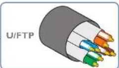
Interference protection codes
Interference protection is classified in the following manner:
U/UTP

where
U = unshielded
F = foil shielding
S = braided shielding
PiMF = Pairs in Metal Foil
Note: Do not use unshielded cables with the DDX modules.
Name Overall Screening Pair Shielding
U/UTP ✗ ✗
F/UTP √ ×
U/FTP ✗ √
S/FTP √ √
or S/STP or PiMF




APPENDIX 2 - FIRMWARE UPGRADES FOR BASIC EXTENDER INSTALLATIONS
Extender systems (or individual DDX-USR units) can be upgraded using a USB stick if required. This is carried out as follows:
Connect the DDX-USR to a compatible display and keyboard; optionally connect to a DDX-CAM module using a Shielded CAT6a or CAT7 data cable to upgrade it at the same time.
2 On the DDX-USR unit, insert a FAT32-formatted USB stick containing the extender firmware upgrade file into one of the front USB ports. Note: The extender firmware upgrade file must be in the root folder.
3 Apply power to the DDX-USR unit and DDX-CAM modules.
IMPORTANT: Ensure power remains uninterrupted throughout the upgrade process.
4 Press-and-hold the recessed reset button for ten seconds until the PWR indicator begins to flash quickly, then release the reset button.
5 When prompted, type in the name of the extender firmware upgrade file and press Enter.
6 Type Y or N as appropriate, when asked if an attached (DDX-CAM) transmitter unit should also be upgraded.
7 The display will show the upgrade progress and confirmation message.
8 If successful the DDX-USR and DDX-CAM modules will automatically be rebooted and the USB stick can be removed.
APPENDIX 3 - OPEN SOURCE LICENSES
This product includes binaries that are derived from the open source community. The modules listed below are licenced under the GNU General Public License v2 and must be provided, in source form, on request:
- u-boot
- hotplug
- linux-arm-freescale
- udev
- busybox
- kobs-ng
• termcap • freetype - iproute
- i2c-tools
This product includes binaries that are derived from the open source community. The modules listed below are licenced under the GNU Lesser General Public License v2.1 and must be provided, in source form, on request:
- libconfig
- directfb
- libdaemon
- nss-mdns
• avahi
In addition to the GPL modules listed, this product also includes binaries derived from 3rd party open sources that have their own license requirements. Each module is listed below with their required copyright statement and distribution conditions.
Module: iperf
"iperf, Copyright (c) 2014-2016, The Regents of the University of California, through Lawrence Berkeley National Laboratory (subject to receipt of any required approvals from the U.S. Dept. of Energy). All rights reserved."
Redistribution and use in source and binary forms, with or without modification, are permitted provided that the following conditions are met:
(1) Redistributions of source code must retain the above copyright notice, this list of conditions and the following disclaimer.
(2) Redistributions in binary form must reproduce the above copyright notice, this list of conditions and the following disclaimer in the documentation and/or other materials provided with the distribution.
(3) Neither the name of the University of California, Lawrence Berkeley National Laboratory, U.S. Dept. of Energy nor the names of its contributors may be used to endorse or promote products derived from this software without specific prior written permission.
THIS SOFTWARE IS PROVIDED BY THE COPYRIGHT HOLDERS AND CONTRIBUTORS "AS IS" AND ANY EXPRESS OR IMPLIED WARRANTIES, INCLUDING, BUT NOT LIMITED TO, THE IMPLIED WARRANTIES OF MERCHANTABILITY AND FITNESS FOR A PARTICULAR PURPOSE ARE DISCLAIMED.
IN NO EVENT SHALL THE COPYRIGHT OWNER OR CONTRIBUTORS BE LIABLE FOR ANY DIRECT, INDIRECT, INCIDENTAL, SPECIAL, EXEMPLARY, OR CONSEQUENTIAL DAMAGES (INCLUDING, BUT NOT LIMITED TO, PROCUREMENT OF SUBSTITUTE GOODS OR SERVICES; LOSS OF USE, DATA, OR PROFITS; OR BUSINESS INTERRUPTION) HOWEVER CAUSED AND ON ANY THEORY OF LIABILITY, WHETHER IN CONTRACT, STRICT LIABILITY, OR TORT (INCLUDING NEGLIGENCE OR OTHERWISE) ARISING IN ANY WAY OUT OF THE USE OF THIS SOFTWARE, EVEN IF ADVISED OF THE POSSIBILITY OF SUCH DAMAGE.
You are under no obligation whatsoever to provide any bug fixes, patches, or upgrades to the features, functionality or performance of the source code (“Enhancements”) to anyone; however, if you choose to make your Enhancements available either publicly, or directly to Lawrence Berkeley National Laboratory, without imposing a separate written license agreement for such Enhancements, then you hereby grant the following license: a non-exclusive, royalty-free perpetual license to install, use, modify, prepare derivative works, incorporate into other computer software, distribute, and sublicense such enhancements or derivative works thereof, in binary and source code form.
===
This software contains source code (src/cjson.{c,h}) that is:
Copyright (c) 2009 Dave Gamble
Permission is hereby granted, free of charge, to any person obtaining a copy of this software and associated documentation files (the "Software"), to deal in the Software without restriction, including without limitation the rights to use, copy, modify, merge, publish, distribute, sublicense, and/or sell copies of the Software, and to permit persons to whom the Software is furnished to do so, subject to the following conditions:
The above copyright notice and this permission notice shall be included in all copies or substantial portions of the Software.
THE SOFTWARE IS PROVIDED "AS IS", WITHOUT WARRANTY OF ANY KIND, EXPRESS OR IMPLIED, INCLUDING BUT NOT LIMITED TO THE WARRANTIES OF MERCHANTABILITY, FITNESS FOR A PARTICULAR PURPOSE AND NONINFRINGEMENT. IN NO EVENT SHALL THE AUTHORS OR COPYRIGHT HOLDERS BE LIABLE FOR ANY CLAIM, DAMAGES OR OTHER LIABILITY, WHETHER IN AN ACTION OF CONTRACT, TORT OR OTHERWISE, ARISING FROM, OUT OF OR IN CONNECTION WITH THE SOFTWARE OR THE USE OR OTHER DEALINGS IN THE SOFTWARE.
===
This software contains source code (src/net.{c,h}) that is:
This software was developed as part of a project at MIT.
Copyright (c) 2005-2007 Russ Cox, Massachusetts Institute of Technology
Permission is hereby granted, free of charge, to any person obtaining a copy of this software and associated documentation files (the "Software"), to deal in the Software without restriction, including without limitation the rights to use, copy, modify, merge, publish, distribute, sublicense, and/or sell copies of the Software, and to permit persons to whom the Software is furnished to do so, subject to the following conditions:
The above copyright notice and this permission notice shall be included in all copies or substantial portions of the Software.
THE SOFTWARE IS PROVIDED "AS IS", WITHOUT WARRANTY OF ANY KIND, EXPRESS OR IMPLIED, INCLUDING BUT NOT LIMITED TO THE WARRANTIES OF MERCHANTABILITY, FITNESS FOR A PARTICULAR PURPOSE AND NONINFRINGEMENT. IN NO EVENT SHALL THE AUTHORS OR COPYRIGHT HOLDERS BE LIABLE FOR ANY CLAIM, DAMAGES OR OTHER LIABILITY, WHETHER IN AN ACTION OF CONTRACT, TORT OR OTHERWISE, ARISING FROM, OUT OF OR IN CONNECTION WITH THE SOFTWARE OR THE USE OR OTHER DEALINGS IN THE SOFTWARE.
[EMPTY]
Contains parts of an earlier library that has:
The authors of this software are Rob Pike, Sape Mullender, and Russ Cox
Copyright (c) 2003 by Lucent Technologies.
Permission to use, copy, modify, and distribute this software for any purpose without fee is hereby granted, provided that this entire notice is included in all copies of any software which is or includes a copy or modification of this software and in all copies of the supporting documentation for such software.
THIS SOFTWARE IS BEING PROVIDED "AS IS", WITHOUT ANY EXPRESS OR IMPLIED WARRANTY. IN PARTICULAR, NEITHER THE AUTHORS NOR LUCENT TECHNOLOGIES MAKE ANY REPRESENTATION OR WARRANTY OF ANY KIND CONCERNING THE MERCHANTABILITY OF THIS SOFTWARE OR ITS FITNESS FOR ANY PARTICULAR PURPOSE.
======
This software contains source code (src/queue.h) that is:
Copyright (c) 1991, 1993
The Regents of the University of California. All rights reserved.
Redistribution and use in source and binary forms, with or without modification, are permitted provided that the following conditions are met:
I. Redistributions of source code must retain the above copyright notice, this list of conditions and the following disclaimer.
2. Redistributions in binary form must reproduce the above copyright notice, this list of conditions and the following disclaimer in the documentation and/or other materials provided with the distribution.
3. Neither the name of the University nor the names of its contributors may be used to endorse or promote products derived from this software without specific prior written permission.
THIS SOFTWARE IS PROVIDED BY THE REGENTS AND CONTRIBUTORS “AS IS” AND ANY EXPRESS OR IMPLIED WARRANTIES, INCLUDING, BUT NOT LIMITED TO, THE IMPLIED WARRANTIES OF MERCHANTABILITY AND FITNESS FOR A PARTICULAR PURPOSE ARE DISCLAIMED. IN NO EVENT SHALL THE REGENTS OR CONTRIBUTORS BE LIABLE FOR ANY DIRECT, INDIRECT, INCIDENTAL, SPECIAL, EXEMPLARY, OR CONSEQUENTIAL DAMAGES (INCLUDING, BUT NOT LIMITED TO, PROCUREMENT OF SUBSTITUTE GOODS OR SERVICES; LOSS OF USE, DATA, OR PROFITS; OR BUSINESS INTERRUPTION) HOWEVER CAUSED AND ON ANY THEORY OF LIABILITY, WHETHER IN CONTRACT, STRICT LIABILITY, OR TORT (INCLUDING NEGLIGENCE OR OTHERWISE) ARISING IN ANY WAY OUT OF THE USE OF THIS SOFTWARE, EVEN IF ADVISED OF THE POSSIBILITY OF SUCH DAMAGE.
@(#)queue.h 8.5 (Berkeley) 8/20/94
[EMPTY]
This software contains source code (src/tcp_window_size.{c,h}) that is:
Copyright (c) 1999,2000,2001,2002,2003
The Board of Trustees of the University of Illinois All Rights Reserved.
Permission is hereby granted, free of charge, to any person obtaining a copy of this software (lperf) and associated documentation files (the "Software"), to deal in the Software without restriction, including without limitation the rights to use, copy, modify, merge, publish, distribute, sublicense, and/or sell copies of the Software, and to permit persons to whom the Software is furnished to do so, subject to the following conditions: Redistributions of source code must retain the above copyright notice, this list of conditions and the following disclaimers.
Redistributions in binary form must reproduce the above copyright notice, this list of conditions and the following disclaimers in the documentation and/or other materials provided with the distribution.
Neither the names of the University of Illinois, NCSA, nor the names of its contributors may be used to endorse or promote products derived from this Software without specific prior written permission.
THE SOFTWARE IS PROVIDED "AS IS", WITHOUT WARRANTY OF ANY KIND, EXPRESS OR IMPLIED, INCLUDING BUT NOT LIMITED TO THE WARRANTIES OF MERCHANTABILITY, FITNESS FOR A PARTICULAR PURPOSE AND NONINFRINGEMENT. IN NO EVENT SHALL THE CONTRIBUTORS OR COPYRIGHT HOLDERS BE LIABLE FOR ANY CLAIM, DAMAGES OR OTHER LIABILITY, WHETHER IN AN ACTION OF CONTRACT, TORT OR OTHERWISE, ARISING FROM, OUT OF OR IN CONNECTION WITH THE SOFTWARE OR THE USE OR OTHER DEALINGS IN THE SOFTWARE.
National Laboratory for Applied Network Research National Center for Supercomputing Applications University of Illinois at Urbana-Champaign http://www.ncsa.uiuc.edu
tcp_window_size.c
by Mark Gates mgates@nlanr.net
set/getsockopt
[EMPTY]
This software contains source code (src/units.{c.h}) that is:
Copyright (c) 1999,2000,2001,2002,2003
The Board of Trustees of the University of Illinois All Rights Reserved.
Permission is hereby granted, free of charge, to any person obtaining a copy of this software (lperf) and associated documentation files (the "Software"), to deal in the Software without restriction, including without limitation the rights to use, copy, modify, merge, publish, distribute, sublicense, and/or sell copies of the Software, and to permit persons to whom the Software is furnished to do so, subject to the following conditions: Redistributions of source code must retain the above copyright notice, this list of conditions and the following disclaimers.
Redistributions in binary form must reproduce the above copyright notice, this list of conditions and the following disclaimers in the documentation and/or other materials provided with the distribution.
Neither the names of the University of Illinois, NCSA, nor the names of its contributors may be used to endorse or promote products derived from this Software without specific prior written permission.
THE SOFTWARE IS PROVIDED "AS IS", WITHOUT WARRANTY OF ANY KIND, EXPRESS OR IMPLIED, INCLUDING BUT NOT LIMITED TO THE WARRANTIES OF MERCHANTABILITY, FITNESS FOR A PARTICULAR PURPOSE AND NONINFRINGEMENT. IN NO EVENT SHALL THE CONTRIBUTORS OR COPYRIGHT HOLDERS BE LIABLE FOR ANY CLAIM, DAMAGES OR OTHER LIABILITY, WHETHER IN AN ACTION OF CONTRACT, TORT OR OTHERWISE, ARISING FROM, OUT OF OR IN CONNECTION WITH THE SOFTWARE OR THE USE OR OTHER DEALINGS IN THE SOFTWARE.
National Laboratory for Applied Network Research
National Center for Supercomputing Applications
University of Illinois at Urbana-Champaign
http://www.ncsa.uiuc.edu
stdio.c
by Mark Gates mgates@nlanr.net
and Ajay Tirumalla tirumala@ncsa.uiuc.edu
input and output numbers, converting with kilo, mega, giga
[EMPTY]
This software contains source code (src/portable_endian.h) that is:
// "License": Public Domain
// I, Mathias Panzenböck, place this file hereby into the public domain. Use it at your own risk for whatever you like.
[EMPTY]
Module: openssl
LICENSE ISSUES
[EMPTY]
The OpenSSL toolkit stays under a dual license, i.e. both the conditions of the OpenSSL License and the original SSLeay license apply to the toolkit. See below for the actual license texts. Actually both licenses are BSD-style Open Source licenses. In case of any license issues related to OpenSSL please contact openssl-core@openssl.org.
OpenSSL License
Copyright (c) 1998-2011 The OpenSSL Project. All rights reserved.
Redistribution and use in source and binary forms, with or without modification, are permitted provided that the following conditions are met:
I. Redistributions of source code must retain the above copyright notice, this list of conditions and the following disclaimer.
-
Redistributions in binary form must reproduce the above copyright notice, this list of conditions and the following disclaimer in the documentation and/or other materials provided with the distribution.
-
All advertising materials mentioning features or use of this software must display the following acknowledgment:
"This product includes software developed by the OpenSSL Project for use in the OpenSSL Toolkit. (http://www.openssl.org/)
- The names "OpenSSL Toolkit" and "OpenSSL Project" must not be used to endorse or promote products derived from this software without prior written permission. For written permission, please contact
openssl-core@openssl.org.
-
Products derived from this software may not be called "OpenSSL" nor may "OpenSSL" appear in their names without prior written permission of the OpenSSL Project.
-
Redistributions of any form whatsoever must retain the following acknowledgment: "This product includes software developed by the OpenSSL Project for use in the OpenSSL Toolkit (http://www.openssl.org/)
THIS SOFTWARE IS PROVIDED BY THE OpenSSL PROJECT "AS IS" AND ANY EXPRESSED OR IMPLIED WARRANTIES, INCLUDING, BUT NOT LIMITED TO, THE IMPLIED WARRANTIES OF MERCHANTABILITY AND FITNESS FOR A PARTICULAR PURPOSE ARE DISCLAIMED. IN NO EVENT SHALL THE OpenSSL PROJECT OR ITS CONTRIBUTORS BE LIABLE FOR ANY DIRECT, INDIRECT, INCIDENTAL, SPECIAL, EXEMPLARY, OR CONSEQUENTIAL DAMAGES (INCLUDING, BUT NOT LIMITED TO, PROCUREMENT OF SUBSTITUTE GOODS OR SERVICES; LOSS OF USE, DATA, OR PROFITS; OR BUSINESS INTERRUPTION) HOWEVER CAUSED AND ON ANY THEORY OF LIABILITY, WHETHER IN CONTRACT, STRICT LIABILITY, OR TORT (INCLUDING NEGLIGENCE OR OTHERWISE) ARISING IN ANY WAY OUT OF THE USE OF THIS SOFTWARE, EVEN IF ADVISED OF THE POSSIBILITY OF SUCH DAMAGE.

This product includes cryptographic software written by Eric Young (eay@cryptsoft.com). This product includes software written by Tim Hudson (tjh@cryptsoft.com).
Original SSLeay License
Copyright (C) 1995-1998 Eric Young (eay@cryptsoft.com)
All rights reserved.
This package is an SSL implementation written by Eric Young (eay@cryptsoft.com).
The implementation was written so as to conform with Netscapes SSL.
This library is free for commercial and non-commercial use as long as the following conditions are aheared to. The following conditions apply to all code found in this distribution, be it the RC4, RSA, Ihash, DES, etc., code; not just the SSL code. The SSL documentation included with this distribution is covered by the same copyright terms except that the holder is Tim Hudson (tjh@cryptsoft.com).
Copyright remains Eric Young's, and as such any Copyright notices in the code are not to be removed. If this package is used in a product, Eric Young should be given attribution as the author of the parts of the library used. This can be in the form of a textual message at program startup or in documentation (online or textual) provided with the package.
Redistribution and use in source and binary forms, with or without modification, are permitted provided that the following conditions are met:
I. Redistributions of source code must retain the copyright notice, this list of conditions and the following disclaimer.
-
Redistributions in binary form must reproduce the above copyright notice, this list of conditions and the following disclaimer in the documentation and/or other materials provided with the distribution.
-
All advertising materials mentioning features or use of this software must display the following acknowledgement:
"This product includes cryptographic software written by Eric Young (eay@cryptsoft.com)" The word 'cryptographic' can be left out if the routines from the library being used are not cryptographic related :-).
- If you include any Windows specific code (or a derivative thereof) from the apps directory (application code) you must include an acknowledgement:
"This product includes software written by Tim Hudson (tjh@cryptsoft.com)" THIS SOFTWARE IS PROVIDED BY ERIC YOUNG ``AS IS'' AND ANY EXPRESS OR IMPLIED WARRANTIES, INCLUDING, BUT NOT LIMITED TO, THE IMPLIED WARRANTIES OF MERCHANTABILITY AND FITNESS FOR A PARTICULAR PURPOSE ARE DISCLAIMED. IN NO EVENT SHALL THE AUTHOR OR CONTRIBUTORS BE LIABLE FOR ANY DIRECT, INDIRECT, INCIDENTAL, SPECIAL, EXEMPLARY, OR CONSEQUENTIAL DAMAGES (INCLUDING, BUT NOT LIMITED TO, PROCUREMENT OF SUBSTITUTE GOODS OR SERVICES; LOSS OF USE, DATA, OR PROFITS; OR BUSINESS INTERRUPTION) HOWEVER CAUSED AND ON ANY THEORY OF LIABILITY, WHETHER IN CONTRACT, STRICT LIABILITY, OR TORT (INCLUDING NEGLIGENCE OR OTHERWISE) ARISING IN ANY WAY OUT OF
THE USE OF THIS SOFTWARE, EVEN IF ADVISED OF THE POSSIBILITY OF SUCH DAMAGE.
The licence and distribution terms for any publicly available version or derivative of this code cannot be changed. i.e. this code cannot simply be copied and put under another distribution licence [including the GNU Public Licence.]
Module: libupnp
Copyright (c) 2000-2003 Intel Corporation
All rights reserved.
Redistribution and use in source and binary forms, with or without modification, are permitted provided that the following conditions are met:
- Redistributions of source code must retain the above copyright notice, this list of conditions and the following disclaimer.
- Redistributions in binary form must reproduce the above copyright notice, this list of conditions and the following disclaimer in the documentation and/or other materials provided with the distribution.
- Neither name of Intel Corporation nor the names of its contributors may be used to endorse or promote products derived from this software without specific prior written permission.
THIS SOFTWARE IS PROVIDED BY THE COPYRIGHT HOLDERS AND CONTRIBUTORS ``AS IS'' AND ANY EXPRESS OR IMPLIED WARRANTIES, INCLUDING, BUT NOT LIMITED TO, THE IMPLIED WARRANTIES OF MERCHANTABILITY AND FITNESS FOR A PARTICULAR PURPOSE ARE DISCLAIMED. IN NO EVENT SHALL INTEL OR CONTRIBUTORS BE LIABLE FOR ANY DIRECT, INDIRECT, INCIDENTAL, SPECIAL, EXEMPLARY, OR CONSEQUENTIAL DAMAGES (INCLUDING, BUT NOT LIMITED TO, PROCUREMENT OF SUBSTITUTE GOODS OR SERVICES; LOSS OF USE, DATA, OR PROFITS; OR BUSINESS INTERRUPTION) HOWEVER CAUSED AND ON ANY THEORY OF LIABILITY, WHETHER IN CONTRACT, STRICT LIABILITY, OR TORT (INCLUDING NEGLIGENCE OR OTHERWISE) ARISING IN ANY WAY OUT OF THE USE OF THIS SOFTWARE, EVEN IF ADVISED OF THE POSSIBILITY OF SUCH DAMAGE.
Module: tzdata
Original TZdata License
This is the Debian prepackaged version of the Time Zone and Daylight Saving Time Data.
It was downloaded from http://www.iana.org/time-zones
Upstream Author: The Internet Assigned Numbers Authority (IANA) Commentary should be addressed to tz@iana.org
Copyright: This database is in the public domain.

SAFETY INFORMATION
• For use in dry, oil free indoor environments only.
- Warning - live parts contained within power adapter(s).
- No user serviceable parts within power adapter(s) - do not dismantle.
- Plug the power adapter(s) into socket outlets close to the module that they are powering.
- Do not use an unearthed power socket or extension cable.
- Do not use a power adapter if its case becomes damaged, cracked or broken or if you suspect that it is not operating properly.
- Replace the power adapter(s) with a manufacturer approved type only.
- If you use a power extension cord with the module, make sure the total ampere rating of the devices plugged into the extension cord does not exceed the cord's ampere rating. Also, make sure that the total ampere rating of all the devices plugged into the wall outlet does not exceed the wall outlet's ampere rating.
- Do not attempt to service the modules yourself.
WARRANTY
Adder Technology Ltd warrants that this product shall be free from defects in workmanship and materials for a period of two years from the date of original purchase. If the product should fail to operate correctly in normal use during the warranty period, Adder will replace or repair it free of charge. No liability can be accepted for damage due to misuse or circumstances outside Adder's control. Also Adder will not be responsible for any loss, damage or injury arising directly or indirectly from the use of this product. Adder's total liability under the terms of this warranty shall in all circumstances be limited to the replacement value of this product.
If any difficulty is experienced in the installation or use of this product that you are unable to resolve, please see the Getting assistance section.
RADIO FREQUENCY ENERGY
A Category 5e (or better) twisted pair cable must be used to connect the units in order to maintain compliance with radio frequency energy emission regulations and ensure a suitably high level of immunity to electromagnetic disturbances.
All cables used with this equipment must be shielded in order to maintain compliance with radio frequency energy emission regulations and ensure a suitably high level of immunity to electromagnetic disturbances.
European EMC directive 2004/108/EC
This equipment has been tested and found to comply with the limits for a class A computing device in accordance with the specifications in the European standard EN55032. These limits are designed to provide reasonable protection against harmful interference. This equipment generates, uses and can radiate radio frequency energy and if not installed and used in accordance with the instructions may cause harmful interference to radio or television reception. However, there is no guarantee that harmful interference will not occur in a particular installation. If this equipment does cause interference to radio or television reception, which can be determined by turning the equipment on and off, the user is encouraged to correct the interference with one or more of the following measures: (a) Reorient or relocate the receiving antenna. (b) Increase the separation between the equipment and the receiver. (c) Connect the equipment to an outlet on a circuit different from that to which the receiver is connected. (d) Consult the supplier or an experienced radio/TV technician for help.
FCC Compliance Statement (United States)
This equipment generates, uses and can radiate radio frequency energy and if not installed and used properly, that is, in strict accordance with the manufacturer's instructions, may cause interference to radio communication. It has been tested and found to comply with the limits for a class A computing device in accordance with the specifications in Subpart J of part 15 of FCC rules, which are designed to provide reasonable protection against such interference when the equipment is operated in a commercial environment. Operation of this equipment in a residential area may cause interference, in which case the user at his own expense will be required to take whatever measures may be necessary to correct the interference. Changes or modifications not expressly approved by the manufacturer could void the user's authority to operate the equipment.
Canadian Department of Communications RFI statement
This equipment does not exceed the class A limits for radio noise emissions from digital apparatus set out in the radio interference regulations of the Canadian Department of Communications.
Contact: www.adder.com/contact-details
Support: www.adder.com/support
Documentation by:

www.ctxd.com
© 2018 Adder Technology Limited
All trademarks are acknowledged.
Part No. MAN-DDX-ADDER • Release 1.5

Index
A
Access permissions 3
Add EDID 23
Audio 39
Audio connections
console 14
Auto Refresh 35
B
Backup 34
C
Cable types 43
Category rating 43
Computer
choosing 38
Computer link
connecting 10
switch 10
Computers
configure 28
Configure pages 20
Connection preset 19
Consoles
configure 24
Control page 19
Crosstalk 43
D
Dashboard page 17
Data link
console 14
Data link connection
computer 9
DDX-CAM 9
DDX Matrix
accessing 16
DDX-USR switches 13
Diagnostics 33
DisplayPort 9
DVI-D 9
E
EDID
applying 30
EDID management 13
Exclusive 19
F
Firmware upgrade
extenders 44
via switch 34
FTP 43
G
Gateway 21
H
Headphone connection 14
Hotkeys 38
HTTPS 16
HTTP Server 21
1
IEC connector 12
Ignore Firmware Mismatch 20
Indicators 40
modules 41
switch 40
Interference
protection 43
IP Address 21
M
MAC Address 21
Maintenance pages 33
Manage EDIDs 23
Microphone connection 14
Mode switches 16
N
Net Mask 21
Network link
connecting 11
switch ||
Network port
temporary connection 16
Network settings 21
0
OSD
viewing 37
OSD Settings 22
P
Password
default 16
PiMF 43
Port
designations 4
reallocation 31
Power connection
console 15
switch 12
Power disconnect 12
Preset Connection 25,26
Primary console 25.26.28.29
Private 19
R
Reallocating ports 31
Reboot System 34
Receivers
configure 27
Recover
failed upgrade 36
receiver 27
transmitter 30
Recovering a receiver 27
Resetting 36
Restore 34
RJ-45 socket 10
s
Safety information 49
Screening 43
Settings 35
Shared access 19
Shielding 43
STP 43
Switches
DDX-USR 13
Sync Tx/Rx Firmware 34
System Default EDID 20
System Operations 34
T
Thumbnails 22,28
Touchscreen 37
Transmitters
configure 30
U
Unique ID 27,30
Upgrade firmware 34,44
UPnP 16
USB
remote module 13
USB connection
computer 9
console 13
User console link
switch 10
Username
default 16
UTP 43
V
Video
remote module 13
Video connection
computer 9
console 13
View only 19
Virtual Control Panel 25,38
W
Warranty 49
Web UI Mode 35
- Contents
- Introduction
- Installation
- Configuration
- Operation
- Further information
- Index
- WELCOME
- Cable type and distance rules
- Access permissions
- VIEW ONLY
- SHARED ACCESS
- EXCLUSIVE
- PRIVATE
- Port designations - DDX10
- Port designations - DDX30
- SUPPLIED ITEMS
- LOCATIONS
- CONNECTIONS
- Computer connections: Video
- Computer connections: USB
- Computer connections: Data link
- Switch (DDX10) connections: Computer links
- To connect a computer link
- Reallocating ports
- Switch (DDX10) connections: User console links
- To connect a user console link
- Switch (DDX30) connections: Computer links
- Switch (DDX30) connections: User console links
- Switch connections: Network link
- To connect a network link
- Switch connections: Options port
- Switch connections: Power
- To connect the power adapter
- To disconnect the power adapter
- Console connections: Video
- To connect the video display
- EDID management
- DDX-USR module switches
- Console connections: USB
- To connect USB devices
- Console connections: Audio
- To connect your speakers
- To connect your headphones/microphone
- Console connections: Data link
- To link the DDX-USR module
- Console connections: Options port
- Console connections: Power
- ACCESSING DDX MATRIX
- To access DDX Matrix
- To temporarily connect a computer to the network port
- USING DDX MATRIX
- The Dashboard page
- Quick guide to creating a new installation
- Primary tasks
- Secondary tasks
- The Control page
- Connection preset
- To connect a console
- To disconnect a console
- The Configure pages
- Central Switch > General
- Central Switch > Network
- DHCP and (Fallback) Address Scheme
- Central Switch > OSD Settings
- Central Switch > Manage EDIDs
- Add EDID
- Configure > Consoles
- Add new
- Edit
- Configure > Consoles > Add new entry
- Recovering a receiver
- Applying a different EDID
- Recovering a transmitter
- To reallocate a port that is already being used
- The Users page
- The Maintenance pages
- Maintenance > Diagnostics
- Maintenance > System Operations
- Recovering an unresponsive transmitter or receiver
- Upgrade Firmware
- Backup
- Sync Tx/Rx Firmware
- Restore
- Reboot System
- Factory Reset
- Maintenance > Settings
- Web UI Mode
- Auto Refresh
- Update
- RESETTING AND RECOVERING
- DDX switch > Boot into recovery image
- DDX switch > Reset
- DDX-USR module > Boot into recovery mode
- DDX-USR module > Reset
- VIEWING THE OSD
- To view the OSD, either:
- Thumbnail images
- Switch information
- Choosing a computer
- To choose a computer using the mouse
- To choose a computer using hotkeys (without viewing the OSD)
- Using the Virtual Control Panel to adjust VGA inputs
- To adjust the image from an analog VGA input
- USB Improvements
- USING AUDIO
- Using audio in a simple extender installation
- Using audio in a full DDX matrix installation
- Managing audio in multi-user situations
- INDICATORS
- DDX switch - Red front panel status indicators
- DDX switch - Green and amber network status indicators
- DDX-USR module - Green and amber status indicators
- DDX-USR module - Red front panel status indicators
- Special condition
- DDX-CAM module - Green and amber status indicators
- GETTING ASSISTANCE
- APPENDIX I - LINK CABLE INTERFERENCE PROTECTION
- Interference protection codes
- APPENDIX 2 - FIRMWARE UPGRADES FOR BASIC EXTENDER INSTALLATIONS
- APPENDIX 3 - OPEN SOURCE LICENSES
- OpenSSL License
- SAFETY INFORMATION
- WARRANTY
- RADIO FREQUENCY ENERGY
- European EMC directive 2004/108/EC
- FCC Compliance Statement (United States)
- Canadian Department of Communications RFI statement
- A
- B
- C
- D
- E
- F
- G
- H
- 1
- M
- N
- 0
- P
- R
- s
- T
- U
- V
- W
Brand : Adder
Model : View DDX CAM
Category : Cables for Computers and Peripherals